

Napoleon XIR3NSB Installation Manual
INSTALLER: LEAVE THIS MANUAL WITH THE APPLIANCE.
HOT GLASS WILL CAUSE
BURNS.
DO NOT TOUCH GLASS UNTIL
COOLED.
NEVER ALLOW CHILDREN TO
TOUCH GLASS.
!
DANGER
A barrier designed to reduce the risk of burns from
the hot viewing glass is provided with this appliance
and shall be installed for the protection of children
and other at-risk individuals.
CONSUMER: RETAIN THIS MANUAL FOR FUTURE REFERENCE.
NEVER LEAVE CHILDREN OR OTHER AT RISK INDIVIDUALS ALONE WITH THE APPLIANCE.
INSTALLATION AND
OPERATING INSTRUCTIONS
CERTIFIED TO CANADIAN AND AMERICAN NATIONAL STANDARDS: CSA 2.22 AND ANSI Z21.50 FOR VENTED GAS FIREPLACES.
XIR3N
EN
FR
PG
43
SAFETY INFORMATION
WARNING
!
If the information in these
instructions are not followed exactly,
a fire or explosion may result
causing property damage, personal
injury or loss of life.
- Do not store or use gasoline or other
flammable vapors and liquids in the vicinity of
this or any other appliance.
- WHAT TO DO IF YOU SMELL GAS:
• Do not try to light any appliance.
• Do not touch any electrical switch; do not
use any phone in your building.
• Immediately call your gas supplier from a
neighbour’s phone. Follow the gas
supplier’s instructions.
• If you cannot reach your gas supplier, call
the fire department.
- Installation and service must be performed
by a qualified installer, service agency or the
supplier.
NATURAL GAS
XIR3P
PROPANE
SAFETY BARRIER
WARNING : FOR INDOOR USE ONLY
This appliance may be installed in
an aftermarket, permanently located,
manufactured home (USA only) or mobile
home, where not prohibited by local codes.
This appliance is only for use with the type
of gas indicated on the rating plate. This
appliance is not convertible for use with
other gases, unless a certified kit is used.
Wolf Steel Ltd., 24 Napoleon Rd., Barrie, ON, L4M 0G8 Canada /
$10.00
Phone (705)721-1212 • Fax (705)720-9081 • www.napoleonfireplaces.com • hearth@napoleonproducts.com
103 Miller Drive, Crittenden, Kentucky, USA, 41030
CERTIFIED
W415-1343 / A / 11.18.16

EN
2
TABLE OF CONTENTS
NOTE: The camera icon indicates video tutorials are available as additional reference, visit
http://mynapoleon.napoleonproducts.com/download/index/44/1
1.0 INSTALLATION OVERVIEW 3
2.0 INTRODUCTION 4
2.1 DIMENSIONS 5
2.2 MINIMUM CLEARANCE TO COMBUSTIBLES 5
2.3 GENERAL INSTRUCTIONS 5
2.4 GENERAL INFORMATION 6
2.5 RATING PLATE INFORMATION 7
3.0 INSTALLATION 8
3.1 LEVELLING THE APPLIANCE 8
3.2 CHIMNEY CONNECTION 9
3.3 GAS INSTALLATION 10
4.0 FINISHING 11
4.1 MINIMUM COMBUSTIBLE MANTEL CLEARANCES 11
4.2 SAFETY SCREEN & DOOR REMOVAL / INSTALLATION 12
4.3 LOG PLACEMENT 13
4.4 OPTIONAL ROCK PLACEMENT 14
4.5 GLOWING EMBERS 14
4.6 LOGO PLACEMENT 14
4.7 BATTERY INSTALLATION 15
5.0 ELECTRICAL INFORMATION 16
5.1 WIRING DIAGRAM 16
6.0 OPERATION 17
6.1 OPERATING AND LIGHTING INSTRUCTIONS 17
6.2 XIR3 OPERATION 18
6.2.1 GENERAL TRANSMITTER LAYOUT 18
6.2.2 APPLIANCE OPERATION 18
6.2.3 HAND HELD REMOTE OPERATIONS 18
6.2.4 TEMPERATURE DISPLAY 19
6.2.5 ROOM THERMOSTAT 19
6.2.6 SMART THERMOSTAT 19
6.2.7 FLAME HEIGHT 19
6.2.8 CHILD PROOF FUNCTION 20
6.2.9 NIGHT LIGHT 20
6.2.10 LOW BATTERY / MANUAL BYPASS 20
6.2.11 IN THE EVENT OF A POWER FAILURE 20
6.2.12 CONTROL MODULE 20
6.2.13 SPLIT FLOW VALVE 21
6.2.14 TIMED BLOWER 21
6.3 ANTI CONDENSATION CONTROL SWITCH 21
7.0 ADJUSTMENTS 22
7.1 PILOT BURNER ADJUSTMENT 22
7.2 VENTURI ADJUSTMENT 22
7.3 FLAME CHARACTERISTICS 23
8.0 MAINTENANCE 24
8.1 ANNUAL MAINTENANCE 24
8.2 CARE OF GLASS 25
8.3 CARE OF PLATED PARTS 25
8.4 DOOR GLASS REPLACEMENT 25
8.5 BURNER REMOVAL 26
8.6 FCM REPLACEMENT 26
8.7 NIGHT LIGHT™ REPLACEMENT 27
8.8 VALVE TRAIN REPLACEMENT 27
9.0 REPLACEMENTS 28
9.1 OVERVIEW 29
9.2 OVERVIEW (PG. 2) 30
9.3 VALVE TRAIN ASSEMBLY 31
9.4 FIREBOX TOP ASSEMBLY 32
10.0 ACCESSORIES 33
10.1 ACCESSORIES (PG. 2) 34
11.0 TROUBLESHOOTING 35
12.0 WARRANTY 38
13.0 SERVICE HISTORY 39
14.0 NOTES 40
NOTE: changes, other than editorial, are denoted by a vertical line in the margin.
W415-1343 / A / 11.18.16
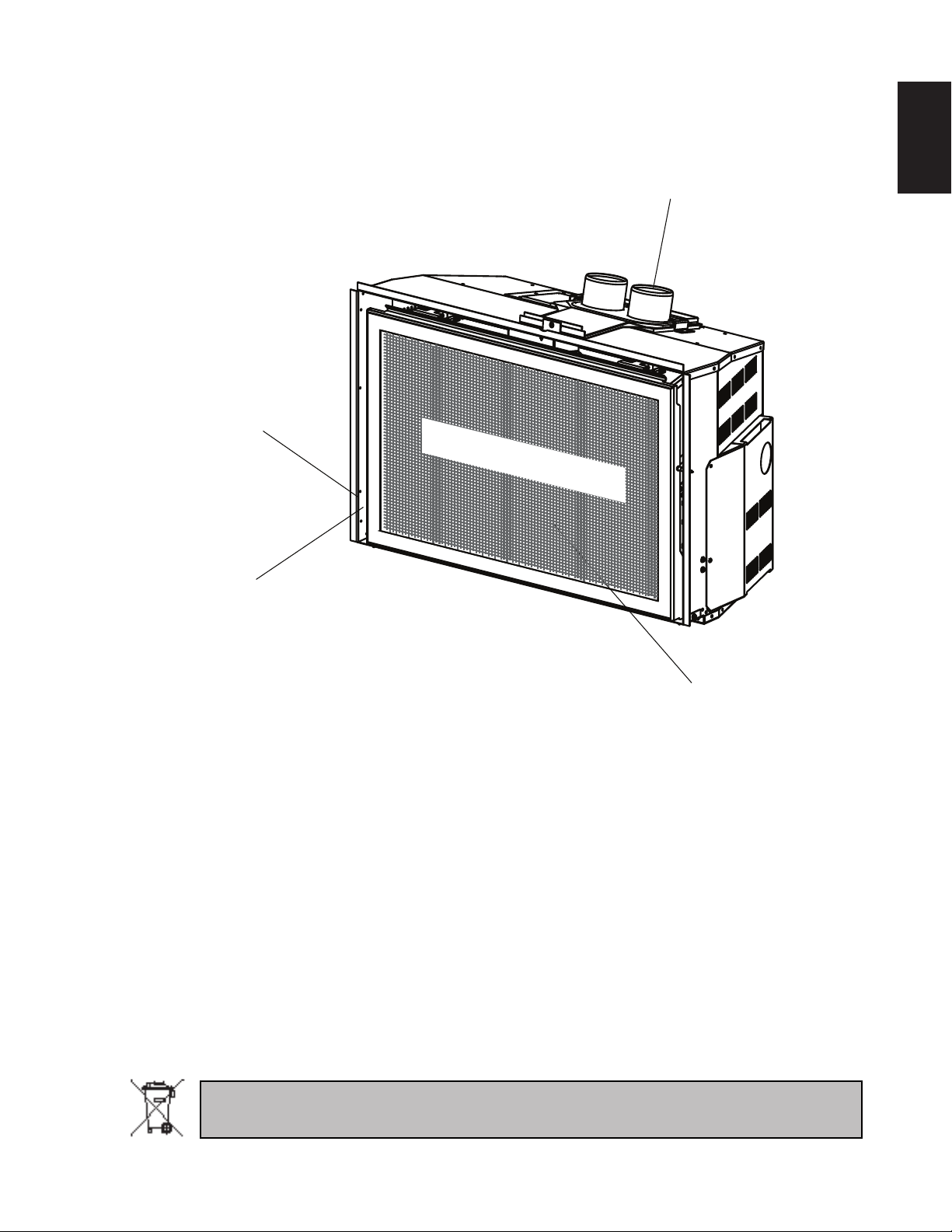
Venting, see “INSTALLATION
- CHIMNEY CONNECTION”
section.
Rating Plate, see “RATING
PLATE INFORMATION”
section.
Logs, see “FINISHING - LOG
PLACEMENT” section.
Batteries, see “BATTERY INSTALLATION” section.
Receiver, see “PROGRAMMING” section.
SAFETY BARRIER
1.0 INSTALLATION OVERVIEW
3
EN
Batteries must be disposed of according to the local laws and regulations. Some batteries may be
recycled, and may be accepted for disposal at your local recycling center. Check with your municipality
for recycling instructions.
W415-1343 / A / 11.18.16

4
!
WARNING
2.0 INTRODUCTION
EN
• THIS APPLIANCE IS HOT WHEN OPERATED AND CAN CAUSE SEVERE BURNS IF CONTACTED.
• ANY CHANGES OR ALTERATIONS TO THIS APPLIANCE OR ITS CONTROLS CAN BE DANGEROUS AND IS
PROHIBITED.
• Do not operate appliance before reading and understanding operating instructions. Failure to operate appliance
according to operating instructions could cause fi re or injury.
• Risk of fi re or asphyxiation do not operate appliance with fi xed glass removed.
• Do not connect 110 volts to the control valve.
• Risk of burns. The appliance should be turned off and cooled before servicing.
• Do not install damaged, incomplete or substitute components.
• Risk of cuts and abrasions. Wear protective gloves and safety glasses during installation. Sheet metal edges may
be sharp.
• Do not burn wood or other materials in this appliance.
• Children and adults should be alerted to the hazards of high surface temperature and should stay away to
avoid burns or clothing ignition.
• Young children should be carefully supervised when they are in the same room as the appliance.
Toddlers, young children and others may be susceptible to accidental contact burns. A physical barrier
is recommended if there are at risk individuals in the house. To restrict access to an appliance, install an
adjustable safety gate to keep toddlers, young children and other at risk individuals out of the room and
away from hot surfaces.
• Clothing or other fl ammable material should not be placed on or near the appliance.
• Due to high temperatures, the appliance should be located out of traffi c and away from furniture and
draperies.
• Ensure you have incorporated adequate safety measure to protect infants/toddlers from touching hot surfaces.
• Even after the appliance is out, the glass and/or screen will remain hot for an extended period of time.
• Check with your local hearth specialty dealer for safety screens and hearth guards to protect children from hot
surfaces. These screens and guards must be fastened to the fl oor.
• Any safety screen, guard or barrier removed for servicing the appliance, must be replaced prior to operating
the appliance.
• The appliance is a vented gas-fi red appliance. Do not burn wood or other materials in the appliance
• It is imperative that the control compartments, burners and circulating blower and its passageway in the appliance
and venting system are kept clean. The appliance and its venting system should be inspected before use and at
least annually by a qualifi ed service person. More frequent cleaning may be required due to excessive lint from
carpeting, bedding material, etc. The appliance area must be kept clear and free from combustible materials,
gasoline and other fl ammable vapors and liquids.
• Under no circumstances should this appliance be modifi ed.
• This appliance must not be connected to a chimney fl ue pipe serving a separate solid fuel burning appliance.
• Do not use this appliance if any part has been under water. Immediately call a qualifi ed service technician to
inspect the appliance and to replace any part of the control system and any gas control which has been under
water.
• Do not operate the appliance with the glass door removed, cracked or broken. Replacement of the glass should be
done by a licensed or qualifi ed service person.
• Do not strike or slam shut the appliance glass door.
• When equipped with pressure relief doors, they must be kept closed while the appliance is operating to prevent
exhaust fumes containing carbon monoxide, from entering into the home. Temperatures of the exhaust escaping
through these openings can also cause the surrounding combustible materials to overheat and catch fi re.
• Only doors / optional fronts certifi ed with the appliance are to be installed on the appliance.
• Keep the packaging material out of reach of children and dispose of the material in a safe manner. As with all
plastic bags, these are not toys and should be kept away from children and infants.
• As with any combustion appliance, we recommend having your appliance regularly inspected and serviced as well
as having a Carbon Monoxide Detector installed in the same area to defend you and your family against Carbon
Monoxide.
• Ensure clearances to combustibles are maintained when building a mantel or shelves above the appliance.
Elevated temperatures on the wall or in the air above the appliance can cause melting, discolouration or damage of
decorations, a T.V. or other electronic components.
• A barrier designed to reduce the risk of burns from the hot viewing glass is provided with this appliance and
shall be installed.
• If the barrier becomes damaged, the barrier shall be replaced with the manufacturer’s barrier for this
appliance.
• Installation and repair should be done by a qualifi ed service person. The appliance should be inspected
before use and at least annually by a professional service person. More frequent cleaning may be required
due to excessive lint from carpeting, bedding material, etc. It is imperative that control compartments,
burners and circulating air passageways of the appliance be kept clean.
3.2C
W415-1343 / A / 11.18.16
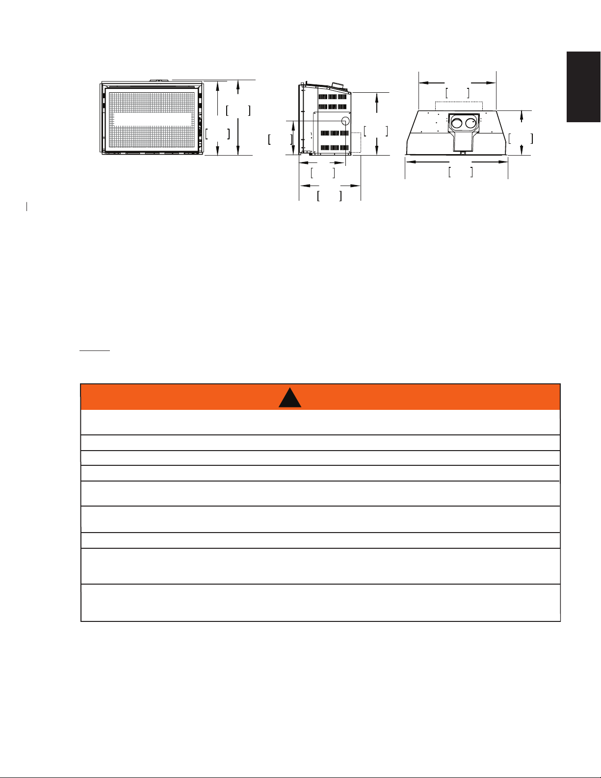
2.1 DIMENSIONS
THIS GAS APPLIANCE SHOULD BE INSTALLED AND SERVICED BY A QUALIFIED INSTALLER
conform with local codes. Installation practices vary from region to region and it is important to know the
specifi cs that apply to your area, for example in Massachusetts State:
• This product must be installed by a licensed plumber or gas fi tter when installed within the commonwealth
• The appliance damper must be removed or welded in the open position prior to installation of an appliance
•
•
• A Carbon Monoxide detector is required in all rooms containing gas fi red appliances.
SURFACES AROUND AND ESPECIALLY ABOVE THE APPLIANCE CAN BECOME HOT. AVOID CONTACT
HIGH PRESSURE WILL DAMAGE VALVE. DISCONNECT GAS SUPPLY PIPING BEFORE PRESSURE TESTING GAS
WARNING
5
21"
SAFETY BARRIER
*REQUIRED DIMENSION WITH THE OPTIONAL BLOWER KIT INSTALLED.
533mm
20 1/2"
521mm
9 1/2"
241mm
12"
305mm
17 1/2"
445mm
2.2 MINIMUM CLEARANCE TO COMBUSTIBLES
This appliance must be recessed into a vented noncombustible wood-burning appliance (prefabricated or
masonry) only. The minimum appliance opening size in which the appliance is to be installed is:
HEIGHT 211/2" (54.6cm) WIDTH 29" (73.7cm) DEPTH *131/2" (34.3cm)
The minimum allowable chimney flue size is 7" (177.8mm) round.
*Add 4" (102mm) for optional blower.
The minimum distance, from the bottom of a combustible mantel projecting 3" (76mm) maximum from the
wall to the top of the appliance, is 14" (35.6cm) (See MINIMUM MANTEL CLEARANCES section).
NOTE: A NON-COMBUSTIBLE HEARTH MUST PROTRUDE A MINIMUM OF 12" (30.5cm) FROM THE
APPLIANCE.
2.3 GENERAL INSTRUCTIONS
22 7/8"
581mm
17 1/2"
445mm
29 5/8"
*
753mm
13 1/4"
337mm
EN
!
ALWAYS LIGHT THE PILOT WHETHER FOR THE FIRST TIME OR IF THE GAS SUPPLY HAS RUN OUT,
WITH THE GLASS DOOR OPENED OR REMOVED.
PROVIDE ADEQUATE CLEARANCE FOR SERVICING AND OPERATING THE APPLIANCE.
PROVIDE ADEQUATE VENTILATION.
NEVER OBSTRUCT THE FRONT OPENING OF THE APPLIANCE.
OBJECTS PLACED IN FRONT OF THE APPLIANCE MUST BE KEPT A MINIMUM OF 48 INCHES
(121.9cm) FROM THE FRONT FACE OF THE APPLIANCE.
WHEN THE APPLIANCE IS OPERATING.
FIRE RISK. EXPLOSION HAZARD.
LINE AT TEST PRESSURES ABOVE 1/2 PSIG. CLOSE THE MANUAL SHUT-OFF VALVE BEFORE PRESSURE
TESTING GAS LINE AT TEST PRESSURES EQUAL TO OR LESS THAN 1/2 PSIG (35mb).
USE ONLY WOLF STEEL APPROVED OPTIONAL ACCESSORIES AND REPLACEMENT PARTS WITH THIS APPLIANCE.
USING NON-LISTED ACCESSORIES (BLOWERS, DOORS, LOUVRES, TRIMS, GAS COMPONENTS, VENTING
COMPONENTS, ETC.) COULD RESULT IN A SAFETY HAZARD AND WILL VOID THE WARRANTY AND CERTIFICATION.
of Massachusetts.
insert or gas log.
The appliance off valve must be a “T” handle gas cock.
The fl exible connector must not be longer than 36 inches (91.4cm).
to
W415-1343 / A / 11.18.16
EN
THIS GAS APPLIANCE SHOULD BE INSTALLED AND SERVICED BY A QUALIFIED INSTALLER to
conform with local codes. Installation practices vary from region to region and it is important to know the
specifi cs that apply to your area, for example in Massachusetts State:
• This product must be installed by a licensed plumber or gas fi tter when installed within the commonwealth
of Massachusetts.
• The appliance damper must be removed or welded in the open position prior to installation of an appliance
insert or gas log.
• The appliance off valve must be a “T” handle gas cock.
• The fl exible connector must not be longer than 36 inches (91.4cm).
• A Carbon Monoxide detector is required in all rooms containing gas fi red appliances.
•
The installation must conform with local codes or, in
absence of local codes, the National Gas and Propane
Installation Code CSA B149.1 in Canada, or the National
Fuel Gas Code, ANSI Z223.1 / NFPA 54 in the United
States. Suitable for mobile home installation if installed in
accordance with the current standard CAN/CSA Z240MH
Series, for gas equipped mobile homes, in Canada or
ANSI Z223.1 and NFPA 54 in the United States.
Some appliances have optional fans or blowers. If an optional fan or blower is installed, the junction box must
be electrically connected and grounded in accordance with local codes, use the current CSA C22.1 Canadian
Electrical Code in Canada or the ANSI/NFPA 70 National Electrical code in the United States.
ALWAYS LIGHT THE PILOT WHETHER FOR THE FIRST TIME OR IF THE GAS SUPPLY HAS RUN OUT,
WITH THE GLASS DOOR OPENED OR REMOVED.
PROVIDE ADEQUATE CLEARANCE FOR SERVICING AND OPERATING THE APPLIANCE.
PROVIDE ADEQUATE VENTILATION.
NEVER OBSTRUCT THE FRONT OPENING OF THE APPLIANCE.
OBJECTS PLACED IN FRONT OF THE APPLIANCE MUST BE KEPT A MINIMUM OF 48 INCHES
(121.9cm) FROM THE FRONT FACE OF THE APPLIANCE.
SURFACES AROUND AND ESPECIALLY ABOVE THE APPLIANCE CAN BECOME HOT. AVOID CONTACT
WHEN THE APPLIANCE IS OPERATING.
FIRE RISK. EXPLOSION HAZARD.
HIGH PRESSURE WILL DAMAGE VALVE. DISCONNECT GAS SUPPLY PIPING BEFORE PRESSURE TESTING GAS
LINE AT TEST PRESSURES ABOVE 1/2 PSIG. CLOSE THE MANUAL SHUT-OFF VALVE BEFORE PRESSURE
TESTING GAS LINE AT TEST PRESSURES EQUAL TO OR LESS THAN 1/2 PSIG (35mb).
USE ONLY WOLF STEEL APPROVED OPTIONAL ACCESSORIES AND REPLACEMENT PARTS WITH THIS APPLIANCE.
USING NON-LISTED ACCESSORIES (BLOWERS, DOORS, LOUVRES, TRIMS, GAS COMPONENTS, VENTING
COMPONENTS, ETC.) COULD RESULT IN A SAFETY HAZARD AND WILL VOID THE WARRANTY AND CERTIFICATION.
!
WARNING
6
The appliance is not approved for installation in a bedroom or bathroom unless the unit is a direct vent
sealed combustion product.
2.4 GENERAL INFORMATION
FOR YOUR SATISFACTION, THIS APPLIANCE HAS BEEN TEST-FIRED TO ASSURE ITS OPERATION AND
QUALITY!
XIR3
www.ncertied.org
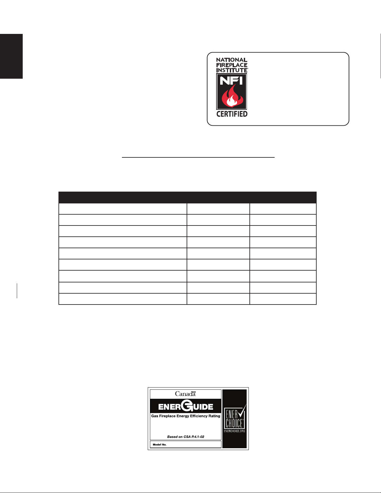
We suggest that our gas
hearth products be installed
and serviced by professionals
who are certied in the U.S.
by the National Fireplace
®
Institute
(NFI) as NFI Gas
Specialists
4.12A
NG P
Altitude (FT) 0-4,500 0-4,500
Max. Input (BTU/HR) 31,000 31,000
Max. Output (BTU/HR) 24,800 24,800
Efficiency (w/the fan on) 80% 80%
A.F.U.E. (maximum value) 77% 77%
Min. Inlet Gas Supply Pressure 4.5"(11mb) WC 11"(27mb) WC
Max. Inlet Gas Supply Pressure 13"(32mb) WC 13"(32mb) WC
W415-1343 / A / 11.18.16
Manifold Pressure (Under Flow Conditions) 3.5"(9mb) WC 10"(25mb) WC
When the appliance is installed at elevations above 4,500ft (1371m), and in the absence of specific
recommendations from the local authority having jurisdiction, the certified high altitude input rating shall be
reduced at the rate of 4% for each additional 1,000ft (305m). Expansion / contraction noises during heating
up and cooling down cycles are normal and to be expected.
This appliance is not approved for closet or recessed installations. It is approved for bathroom, bedroom
and bed-sitting room installations and is suitable for mobile homes. The natural gas model is suitable for
installation in a mobile home that is permanently positioned on its site and fuelled with natural gas.
A barrier designed to reduce the risk of burns from the hot viewing glass is provided with the
appliance and must be installed.
67.0%
XIR3

2.5 RATING PLATE INFORMATION
SAMPLE
7
DO NOT TURN ON IF CHILDREN OR OTHER AT RISK INDIVIDUALS
ARE NEAR THE FIREPLACE. DIRECT VENT GAS FIREPLACE.
SUITABLE FOR BEDROOM, BATHROOM AND BED-SITTING
ROOM INSTALLATION. SUITABLE FOR MOBILE HOME INSTALLATION
IF INSTALLED IN ACCORDANCE WITH THE CURRENT STANDARD
CAN/CSA Z240MH SERIES GAS EQUIPPED MOBILE HOMES, IN
CANADA OR IN THE UNITED STATES THE MANUFACTURED HOME
CONTRUCTION AND SAFETY STANDARD, TITLE 24 CFR, PART 3280.
WHEN THIS US STANDARD IS NOT APPLICABLE USE THE
STANDARD FOR FIRE SAFETY CRITERIA FOR MANUFACTURED
HOME INSTALLATIONS, SITES AND COMMUNITIES, ANSI / NFPA
501A.FOR USE WITH BARRIER W565-0133. FOLLOW THE INSTALLATION
INSTRUCTIONS LOCATED IN THE INSTALLATION MANUA
THIS VENTED GAS FIREPLACE IS NOT FOR USE WITH
CONFORMS TO / CONFORME AUX: ANSI Z21.50-2014, CERTIFIED TO / CERTIFIE CSA 2.22-2014 VENTED GAS FIREPLACE / FOYER À GAZ VENTILÉ.
CER TIFIED
L.
NATURAL GAS / GAZ MODEL
XIR3N XIR3PCXIR3N
PRESSION AU COLLECTEUR: 3.5” D’UNE COLONNE D’EAU
PRESSION D’ALIMENTATION MINIMALE: 4.5” D’UNE COLONNE D’EAU
PERSSION D’ALIMENTATION MAXIMALE:
4500FT (0-1370m) ALTITUDE/ELEVATION 4500FT (0-1370m)
11,000 BTU/h REDUCED INPUT/ALIMENTATION REDUITE 16,000 BTU/h
MANIFOLD PRESSURE: 3.5” WATER COLUMN
MINIMUM SUPPLY PRESSURE: 4.5” WATER COLUMN
MAXIMUM SUPPLY PRESSURE:
7.0” WATER COLUMN
7.0” D’UNE COLONNE D’EAU
P.4: 67%
AIR FILTERS. FOR USE WITH GLASS DOORS CERTIFIED
FOR THIS UNIT ONLY. NOT FOR USE WITH SOLID FUEL.
WARNING:
DO NOT ADD ANY MATERIAL TO THE APPLIANCE THAT WILL COME IN
CONTACT WITH THE FLAMES, OTHER THAN THAT SUPPLIED BY THE MANUFACTURER
WITH THE APPLIANCE.
DECORATIVE PRODUCT: NOT FOR USE AS A HEATING APPLIANCE
ELECTRICAL RATING:
THE APPLIANCE MUST BE VENTED USING THE APPROPRIATE WOLF STEEL VENT KITS. SEE
OWNER’S INSTALLATION MANUAL FOR VENTING SPECIFICS. PROPER REINSTALLATION AND
RESEALING IS NECESSARY AFTER SERVICING THE VENT-AIR INTAKE SYSTEM.
WARNING:
MINIMUM FIREPLACE SIZE IS: HEIGHT 20.5”, DEPTH 13.5”, WIDTH 29”. THE MINIMUM INSIDE
FLUE SIZE IS 7”. THE MINIMUM DISTANCE FROM THE BOTTOM OF A COMBUSTIBLE MANTEL
PROJECTING A MAXIMUM 3” FROM THE WALL TO THE TOP OF THE UNIT IS 14”. SEE OWNER’S
MANUAL FOR GREATER EXTENSIONS.
OPTIONAL FAN KIT - GZ550-KT, GD65.
WOLF STEEL LTD.
24 NAPOLEON ROAD, BARRIE. ONTARIO L4M 0G8 CANADA
115V 1.5AMP 60HZ
FOR INSTALLATION INTO A VENTED NON-COMBUSTIBLE FIREPLACE ONLY. THE
NE PAS ALLUMER SI DES ENFANTS OU D’AUTRES INDIVIDUS À RISQUE
PROXIMITÉ DU FOYER. FOYER À GAZ VENTILÉ HOMOLOGUÉ POUR INSTALLATION
DANS UNE CHAMBRE À COUCHER, UNE SALLE DE BAIN ET UN STUDIO. APPROPRIÉ
POUR INSTALLATION DANS UNE MAISON MOBILE SI SON INSTALLATION EST
CONFORME AUX EXIGENCES DE LA NORME CAN/CSA Z240MH SÉRIE DE MAISONS
MOBILES ÉQUIPÉES AU GAZ, EN VIGUEUR AU CANADA, OU AUX ÉTATS-UNIS, SELON
LA NORME DE SÉCURITÉ ET DE CONSTRUCTION DE MAISONS MANUFACTURÉES,
ROF DEIFITREC
RUOP EEIFITREC
MODEL
MANIFOLD PRESSURE: 10” WATER COLUMN
PRESSION AU COLLECTEUR: 10” D’UNE COLONNE D’EAU
MINIMUM SUPPLY PRESSURE: 11” WATER COLUMN
PRESSION D’ALIMENTATION MINIMALE: 11” D’UNE COLONNE D’EAU
MAXIMUM SUPPLY PRESSURE: 13” WATER COLUMN
PERSSION D’ALIMENTATION MAXIMALE: 13” D’UNE COLONNE D’EAU
P.4: 67%
TITRE 24 CFR, SECTION 3280. DANS LE CAS OÙ CETTE NORME DES ÉTATS-UNIS
NE PEUT ÊTRE APPLIQUÉE, SE RÉFÉRER À LA NORME RELATIVE AU CRITÈRE DE
ASU ADANAC
MESURES DE SÉCURITÉ CONTRE L'INCENDIE POUR LES INSTALLATIONS DANS LES
647161# ECNEREFER
MAISONS MANUFACTURÉES, LES SITES ET LES COMMUNAUTÉS, ANSI/NFPA 501A.
POUR UNE UTILISER AVEC BARRIÈRE W565-0133. SUIVEZ LES INSTRUCTIONS
D'INSTALLATION SE TROUVENT DANS LE MANUEL D'INSTALLATION
PROPANE MODEL
h/UTB 000,13 NOITATNEMILA/TUPNI h/UTB 000,13
CE FOYER À GAZ VENTILÉS NE DOIT PAS ÊTRE UTILISÉ
CONJOINTEMENT AVEC DES FILTRES À AIR. UTILISER AVEC LES
PORTES VITRÉES HOMOLOGUÉES AVEC CETTE UNITÉ SEULEMENT. UN COMBUSTIBLE SOLIDE NE DOIT PAS ETRE UTILISE
AVEC CET APPAREIL.
AVERTISSEMENT:
ENTRER EN CONTACT AVEC LES FLAMMES AUTR
APPAREIL PAR LE FABRICANT.
PRODUIT DÉCORATIF: NE PAS UTILSER COMME APPAREIL DE CHAUFFAGE.
CLASS :
L’APPAREIL DOIT EVACUER SES GAZ EN UTILISANT L’ENSEMBLE D’EVACUATION PROPRE A WOLF STEEL.
REFERER AU MANUEL D’INSTALLATION DE PROPRIETAIRE POUR L’EVACUATION PRECISE. IL EST IMPORTANT DE
BIEN REINSTALLER ET RESCELLER L’EVENT APRES AVOIR ASSURE LE MAINTIEN DU SYSTEME DE PRISE D’AIR.
ATTENTION :
SONT: HAUTER 21.5”, PROFONDEUR 13.5”, LARGEUR 29”. LE DIAMETRE INTERIEUR MINIMUM DE CONDUIT
D’EVACUATION EST DE 7”. LA DISTANCE MINIMALE, DU BAS DU MANTEAU COMBUSTIBLE FORMANT UNE
PROJECTION MAXIMALE DE 3” DU MUR AU DESSUS DE LA GARNITURE NORMALE EST 14”. REFERER AU MANUEL
D’INSTALLATION POUR DES EXTENSIONS PLUS GRANDES.
SERIAL NUMBER/NO. DE SERIE:
N'A JOUTEZ PAS A CET APPAREIL AUCUN MATERIAU DEVANT
115V, 1.5AMP, 60HZ
POUR INSTALLATION DANS UN FOYER VENTILE EN MACONNERIE. LES DIMENSIONS MINIMUMS
.
CXIR3P
E QUE CELUI QUI EST FOURNI AVEC CET
SOUFFLERIE OPTIONELLE
XIR3/CXIR3
GZ550-KT, GD65.
SONT À
W385-1972 / A
EN
INSTALLER: It is your responsibility to check off the appropriate box on the rating plate according to
the model, venting and gas type of the appliance.
For rating plate location, see “INSTALLATION OVERVIEW” section.
This illustration is for reference only. Refer to the rating plate on the appliance for accurate information.
NOTE: The rating plate must remain with the appliance at all times. It must not be removed.
W415-1343 / A / 11.18.16
8
Clean out ashes from the inside of the wood-burning appliance. Make sure that the chimney and wood-burning
appliance are in a clean and sound condition and constructed of non-combustible materials. If necessary have
any repair work done by a qualifi ed person before installing the insert. Remove the existing appliance damper
sides or bottom of the appliance in a proper workman like manner. This access hole must be plugged with non-
WARNING
Move the appliance close to its fi nal position. This appliance is equipped with levelling screws located on the
base. Level using the levelling screws. Levelling the appliance will eliminate rocking or excessive noise when
the fan is in operation. Once the appliance is level, move it partially into place to allow for all connections to be
made. It is not practical to level the appliance once it has been installed. Determine the required depth prior to
installing the appliance and adjust the levelling screws accordingly.
3.0 INSTALLATION
EN
!
RISK OF FIRE, MAINTAIN SPECIFIED AIR SPACE CLEARANCES TO VENT PIPE AND APPLIANCE.
or lock into an open position.
WARNING: THIS FIREPLACE HAS BEEN CONVERTED FOR USE WITH A GAS FIREPLACE
INSERT ONLY AND CANNOT BE USED FOR BURNING WOOD OR SOLID FUELS UNLESS ALL ORIGINAL
Using screws, attach the appliance warning tag
to the inside of the fi rebox of the appliance into
which the insert is being installed.
The sheet-metal parts of the appliance, in which
the gas appliance insert is to be installed, must
not be cut.
If the wood-burning factory-built appliance has
no gas access hole(s) provided, an access hole of 1½ inch (38.1mm) or less may be drilled through the lower
combustible insulation after the gas supply line has been installed.
Ensure that existing chimney cleanouts fi t properly.
The refractory, glass doors, screen rails, screen mesh and log grates may be removed from the existing
appliance before installing the gas appliance insert.
PARTS HAVE BEEN REPLACED AND THE FIREPLACE IS RE-APPROVED BY THE AUTHORITY HAVING
JURISDICTION.
ATTENTION: CE FOYER A ETE CONVERTI AFIN D’ETRE UTILISE SEULEMENT
COMME FOYER ENCASTRE AU GAZ ET NE PEUT ETRE UTILSE POUR BRULER DU BOIS OU
TOUT AUTRE COMBUSTIBLE SOLIDE, SANS QUE TOUTES LES PIECES ORIGINALES AIENT
ETE REMPLACEES ET QUE LE FOYER SOIT APPROUVE DE NOUVEAU PAR LES AUTORITES
AYANT JURIDICTION.
ADVERTENCIA: ESTA CHIMENEA SE REMODELÓ PARA USARSE SOLO CON UNA
INSERCIÓN DE CHIMENEA A GAS Y NO PUEDE USARSE PARA QUEMAR MADERA NI COMBUSTIBLES
SÓLIDOS, A MENOS QUE SE HAYAN REEMPLAZADO TODAS LAS PIEZAS ORIGINALES, Y LA AUTORIDAD JURISDICCIONAL LA HAYA VUELTO A APROBAR.
W385-0199_B
Smoke shelves, shields and baffl es may be removed if attached by mechanical fasteners.
The ventilation openings in the existing appliance may be obstructed by the backer plates, aluminium trim etc.
but these parts are not to be applied so as to have an airtight seal.
68.4B
3.1 LEVELLING THE APPLIANCE
67.2
W415-1343 / A / 11.18.16
3.2 CHIMNEY CONNECTION
Chimney installation must conform to both national and local code requirements. The chimney must be lined
with one 3" (76mm) diameter liner for intake and one 3" (76mm) diameter liner for exhaust. The minimum and
maximum vent lengths are 10' (3m) and 35' (10m) respectively. Recommended kits come in 3 lengths:
2-3" (50.8mm-76.2mm) DOUBLE PLY ALUMINUM LINER-INLET AND EXHAUST:
GDI-320KT VENT KIT 20FT
GDI-325KT VENT KIT 25 FT
GDI-335KT VENT KIT 35 FT
While the liners must be continuous from the appliance to the chimney cap,
to achieve the needed length, they may be coupled, using an approved
coupler.
We recommend that exhaust vents that pass through unheated spaces,
such as tall exterior chimneys, be wrapped in a protective sleeve to minimize
condensation and reverse flow symptoms. See "TROUBLESHOOTING"
section for details.
This appliance is approved for use with a 3" (76mm) exhaust and air intake.
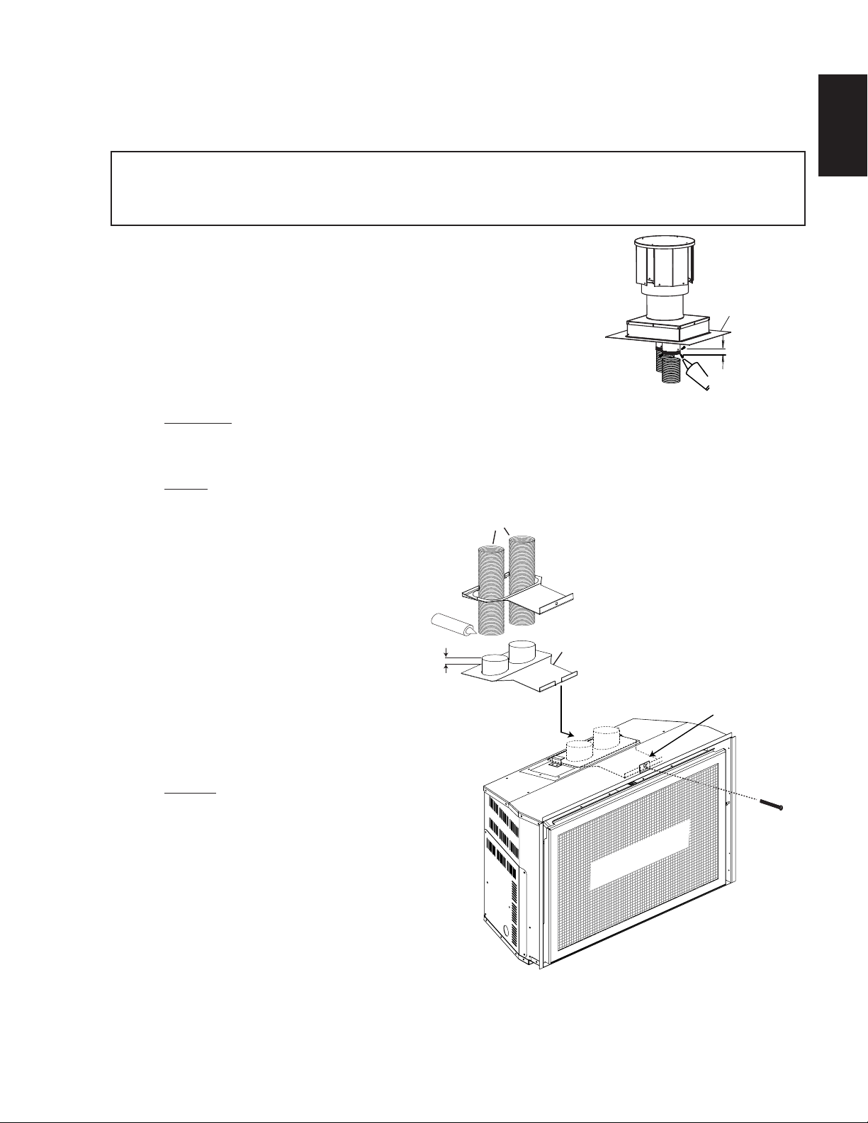
A. OUTSIDE: Slip the one end of a liner a minimum of 2"( 51mm)
over the sleeve of the air terminal. Secure using 3 screws. Then seal the joint and screw heads with
high temperature sealant. Repeat with the other liner.
EXHAUST
INTAKE
9
EN
FLASHING
PLATE
2” (50.8mm)
OVERLAP
SEALANT
HI-TEMP
NOTE: We recommend that the other end of the exhaust liner be marked to eliminate the
exhaust liner being connected
to the intake collar at the
3” (76.2mm)
LINERS
appliance.
B. Gently stretch the liners to the
required lengths and insert
into the chimney. Trim and fit
the flashing plate to suit the
chimney termination. Place the
air terminal onto the top of the
HIGH TEMP
SEALANT
2” (50.8mm)
OVERLAP
SLIDER
MOUNTING
PLATE
chimney. Make weather tight
by sealing with caulking (not
supplied). Fasten to the chimney
with screws and plugs (not
supplied).
C. INSIDE: Remove the securing
INTAKE
EXHAUST
VENT MOUNT
ASSEMBLY
SECURING
screw from the front of the vent
mounting plate. Pull the vent
mounting plate only, back into
the track, to the front stop. Start
the slider back into position. Re-
SAFETY BARRIER
secure the screw. The appliance
may now be pushed into its
final position inside the wood
burning appliance, and the screw
tightened until the slider has
been pulled tight to the front stop.
SCREW
D. Route the flex liners through the slider. Attach and secure the liners to the vent mounting plate using
the same procedure as before, ensuring that the marked exhaust liner is attached to the exhaust
collar.
W415-1343 / A / 11.18.16
10
Installation and servicing to be done by a qualifi ed installer.
•
•
•
current CAN/CSA-B149.1 Installation Code in Canada or to the current National Fuel Gas Code, ANSI
•
• The gas line fl ex-connector should be installed to provide suffi cient movement for shifting the burner
•
WARNING
RISK OF FIRE, EXPLOSION OR ASPHYXIATION. ENSURE THERE ARE NO IGNITION SOURCES SUCH AS
PERFORMED BY A QUALIFIED SERVICE TECHNICIAN. ASSURE THAT A CONTINUOUS GAS FLOW IS AT
3.3 GAS INSTALLATION
EN
!
SPARKS OR OPEN FLAMES.
SUPPORT GAS CONTROL WHEN ATTACHING GAS SUPPLY PIPE TO PREVENT DAMAGING GAS LINE.
ALWAYS LIGHT THE PILOT WHETHER FOR THE FIRST TIME OR IF THE GAS SUPPLY HAS RUN OUT
WITH THE GLASS DOOR OPENED OR REMOVED. PURGING OF THE GAS SUPPLY LINE SHOULD BE
THE BURNER BEFORE CLOSING THE DOOR. ENSURE ADEQUATE VENTILATION. FOR GAS AND
ELECTRICAL LOCATIONS, SEE “DIMENSIONS” SECTION.
ALL GAS CONNECTIONS MUST BE CONTAINED WITHIN THE APPLIANCE WHEN COMPLETE.
HIGH PRESSURE WILL DAMAGE VALVE. DISCONNECT GAS SUPPLY PIPING BEFORE TESTING GAS
LINE AT TEST PRESSURES ABOVE 1/2 PSIG.
VALVE SETTINGS HAVE BEEN FACTORY SET, DO NOT CHANGE.
Move the appliance into position and secure.
If equipped with a fl ex connector the appliance is designed to accept a 1/2” (13mm) gas supply.
Without the connector it is designed to accept a 3/8” (9.5mm) gas supply. The appliance is equipped
with a manual shut off valve to turn off the gas supply to the appliance.
Connect the gas supply in accordance to local codes. In the absence of local codes, install to the
Z223.1 / NFPA 54 in the United States.
When fl exing any gas line, support the gas valve so that the lines are not bent or kinked.
assembly on its side to aid with servicing components.
Check for gas leaks by brushing on a soap and water solution. Do not use open fl ame.
30.1A
W415-1343 / A / 11.18.16
H
D
F
G
MANTEL DEPTH
0” (mm)
HEIGHT
MANTEL
E
C
B
A
WARNING
14”
(35.6cm)
17”
(43.2cm)
16”
(40.6cm)
15”
(38.1cm)
6”(152.4mm)
MANTEL
5”(127mm)
3” (76.2mm)
4”(101.6mm)
201/2”
(52.1cm)
4.0 FINISHING
11
!
WARNING
RISK OF FIRE!
NEVER OBSTRUCT THE FRONT OPENING OF THE APPLIANCE.
IF FINISHING THE FRONT OF THE APPLIANCE, IT MUST BE FINISHED WITH ANY NON-
COMBUSTIBLE MATERIAL SUCH AS BRICK, MARBLE, GRANITE, ETC.
DO NOT STRIKE, SLAM OR SCRATCH GLASS. DO NOT OPERATE APPLIANCE WITH GLASS
REMOVED, CRACKED, BROKEN OR SCRATCHED.
FACING AND/OR FINISHING MATERIAL MUST NEVER OVERHANG INTO THE APPLIANCE OPENING.
72.1B
4.1 MINIMUM COMBUSTIBLE MANTEL CLEARANCES
!
RISK OF FIRE, MAINTAIN ALL SPECIFIED AIR SPACE CLEARANCES TO COMBUSTIBLES. FAILURE
TO COMPLY WITH THESE INSTRUCTIONS MAY CAUSE A FIRE OR CAUSE THE APPLIANCE TO
OVERHEAT. ENSURE ALL CLEARANCES (I.E. BACK, SIDE, TOP, VENT, MANTEL, FRONT, ETC.) ARE
CLEARLY MAINTAINED.
WHEN USING PAINT OR LACQUER TO FINISH THE MANTEL, THE PAINT OR LACQUER MUST BE
HEAT RESISTANT TO PREVENT DISCOLOURATION.
73.1
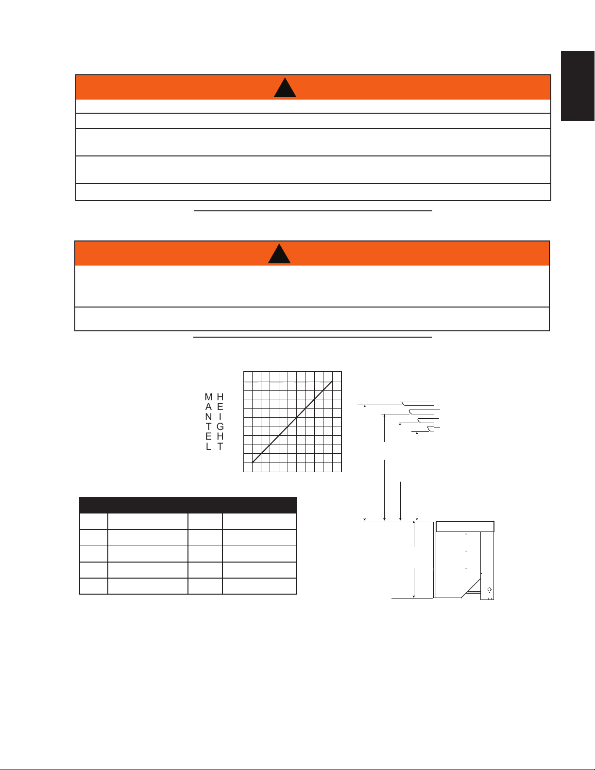
Combustible mantel clearance can vary according to the mantel depth. Use the graph to help evaluate the
clearance needed. These same requirements apply to any combustibles protruding on either side of the
appliance.
EN
MANTEL DIMENSIONS
Ref Height Ref Depth
A
B
C
D
17" (43.2cm)
16" (40.6cm)
15" (38.1cm)
14” (35.6cm)
E
F
G
H
6" (152mm)
5" (127mm)
4" (102mm)
3" (76mm)
W415-1343 / A / 11.18.16

12
WARNING
IF EQUIPPED WITH DOOR LATCHES THAT ARE PART OF A SAFETY RELIEF SYSTEM, THEY MUST BE
BEFORE DOOR IS REMOVED TURN THE APPLIANCE OFF AND WAIT UNTIL APPLIANCE IS COOL TO
SAFETY SCREEN
4.2 SAFETY SCREEN & DOOR REMOVAL / INSTALLATION
EN
!
GLASS MAY BE HOT, DO NOT TOUCH GLASS UNTIL COOLED.
PROPERLY ENGAGED. DO NOT OPERATE THE APPLIANCE WITH LATCHES DISENGAGED.
FACING AND/OR FINISHING MATERIALS MUST NOT INTERFERE WITH AIR FLOW THROUGH AIR
OPENINGS, LOUVRE OPENINGS, OPERATION OF LOUVRES OR DOORS OR ACCESS FOR
SERVICE. OBSERVE ALL CLEARANCES WHEN APPLYING COMBUSTIBLE MATERIALS.
THE TOUCH. DOORS ARE HEAVY AND FRAGILE SO HANDLE WITH CARE.
75.1A
A barrier designed to reduce the risk of burns from the hot viewing glass is provided with the
appliance and shall be installed.
Before the glass door can be removed, the safety screen must be removed. Lift the safety screen off the 4
side pins and remove from the appliance.
SAFETY SCREEN
SAFETY SCREEN
The optional front must be removed to allow the door to be opened or closed. Release the top left and right
door latches, located at the top of the door. Tilt forward and lift from slots.
Reverse these steps to re-install the safety screen and door. Ensure safety screen is installed correctly.
W415-1343 / A / 11.18.16
4.3 LOG PLACEMENT
WARNING
!
FAILURE TO POSITION THE LOGS IN ACCORDANCE WITH THESE DIAGRAMS OR FAILURE TO USE
ONLY LOGS SPECIFICALLY APPROVED WITH THIS APPLIANCE MAY RESULT IN PROPERTY
DAMAGE OR PERSONAL INJURY.
LOGS MUST BE PLACED IN THEIR EXACT LOCATION IN THE APPLIANCE. DO NOT MODIFY THE
PROPER LOG POSITIONS, SINCE APPLIANCE MAY NOT FUNCTION PROPERLY AND DELAYED
IGNITION MAY OCCUR.
THE LOGS ARE FRAGILE AND SHOULD BE HANDLED WITH CARE.
76.1A
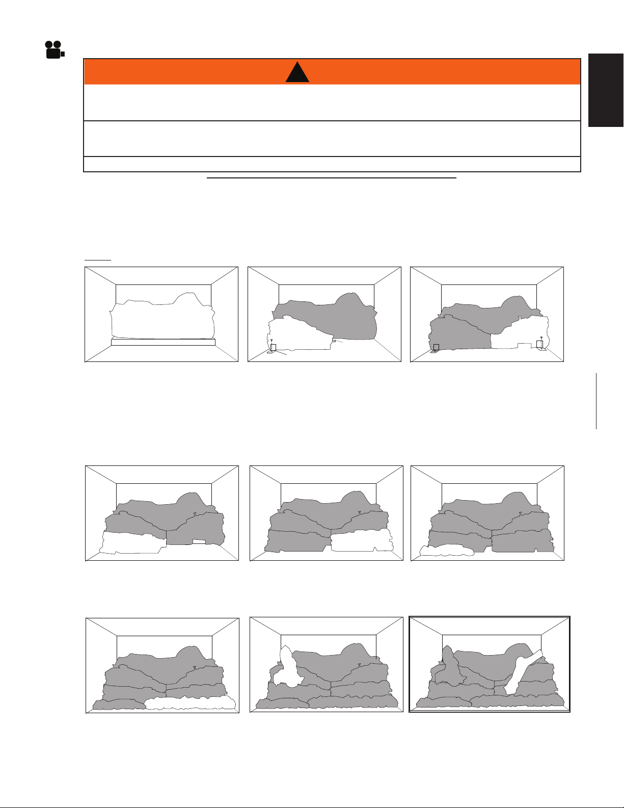
PHAZERTM logs and glowing embers exclusive to Napoleon, provide a unique and realistic glowing effect that
is different in every installation. Take the time to carefully position the glowing embers for a maximum glowing
effect.
Log colours may vary. During the initial use of the appliance, the colours will become more uniform as colour
pigments burn in during the heat activated curing process.
NOTE: Log support brackets are supplied in the manual baggie.
13
EN
A. Place the rear log into position
lining up the holes in the bottom with
the studs located at the rear of the
firebox. Ensure it is tight to the burner.
D. Place the left front log into
position, lining up the 2 holes in the
bottom with the studs located on
the left side of the burner.
PIN
LOG SUPPORT
B. Insert a pin (supplied) into the
right end of the left middle log
using the left log support in front
of the left middle log to hold log in
place.
E. Place the right front log into
position, lining up the 2 holes in the
bottom with the studs located on
the right side of the burner.
C. Insert the right middle log end
onto the left log pin using the right
log support in front of the right
middle log to hold log in place.
Adjust the log supports tight to
these logs to hold them in an
upright position and ensure they are
tight to the burner.
F. Position the left charcoal strip in
front of the left front log, lining up
the 2 holes in the bottom with the
2 front left studs.
G. Position the right charcoal strip
in front of the right front log, lining
up the 2 holes in the bottom with
the 2 front right studs.
H. Position a pin into the left side
hole of the left middle log, move
the left crossover log into position,
lining up the top hole with the pin.
I. Position a pin into the right side
hole of the right middle log, move
the right crossover log into position,
lining up the top hole with the pin.
W415-1343 / A / 11.18.16

EN
Remove the backing of the logo supplied and place on the glass viewing
½"
!
WARNING
14
4.4 OPTIONAL ROCK PLACEMENT
REAL ROCKS MUST NOT BE USED IN THIS APPLIANCE. HEAT WILL CAUSE THEM TO EXPLODE
Before beginning with the installation, remove the door and all burner media from the appliance including logs
and charcoal strips. Retain the glowing embers.
A. Randomly place the rocks onto the media tray, around, but not on the burner ports or pilot area.
B. Rocks can be carefully stacked. You must ensure that none would fall onto the burner or pilot
while in operation.
C. Turn on gas and electrical supply.
D. Reinstall the glowing embers over the burner.
E. Reinstall the door.
4.5 GLOWING EMBERS
Tear the embers into pieces and place along the front row of ports covering all of the burner area in front of
the small logs. Care should be taken to shred the embers into thin, small irregular pieces as only the exposed
edges of the fibre hairs will glow. The ember material will only glow when exposed to direct flame;
however, care should be taken to not block the burner ports.
Blocked burner ports can cause an incorrect flame pattern, carbon deposits and delayed ignition. PHAZERTM
logs glow when exposed to direct flame. Use only certified "glowing embers" and PHAZERTM logs available
from your authorized dealer / distributor.
4.6 LOGO PLACEMENT
(12.7mm)
door, as indicated.
LOGO
½"
(12.7mm)
97.1A
W415-1343 / A / 11.18.16
4.7 BATTERY INSTALLATION
15
4 "AA" batteries must be installed into the receiver before operation is
possible in the XIR3. The receiver is located in the bottom left corner of
the appliance.
RECEIVER
If receiver removal is necessary, remove the left access panel from the front
of the appliance. Remove the 2 screws holding the receiver in place. Pull
the receiver through the access hole and replace.
EN
RECEIVER PLATE
SCREWS
W415-1343 / A / 11.18.16
16
WARNING
SERVICE TECHNICIAN IMMEDIATELY TO HAVE THE APPLIANCE INSPECTED FOR DAMAGE TO THE
5.0 ELECTRICAL INFORMATION
EN
DO NOT USE THIS APPLIANCE IF ANY PART HAS BEEN UNDER WATER. CALL A QUALIFIED
RISK OF ELECTRICAL SHOCK OR EXPLOSION. DO NOT WIRE 110V TO THE VALVE OR TO THE
APPLIANCE WALL SWITCH. INCORRECT WIRING WILL DAMAGE CONTROLS.
ALL WIRING SHOULD BE DONE BY A QUALIFIED ELECTRICIAN AND SHALL BE IN COMPLIANCE
WITH LOCAL CODES. IN THE ABSENCE OF LOCAL CODES, USE THE CURRENT CSA22.1 CANADIAN
ELECTRIC CODE IN CANADA OR THE CURRENT NATIONAL ELECTRIC CODE ANSI/NFPA NO. 70 IN
ALWAYS LIGHT THE PILOT WHETHER FOR THE FIRST TIME OR IF THE GAS SUPPLY HAS RUN OUT,
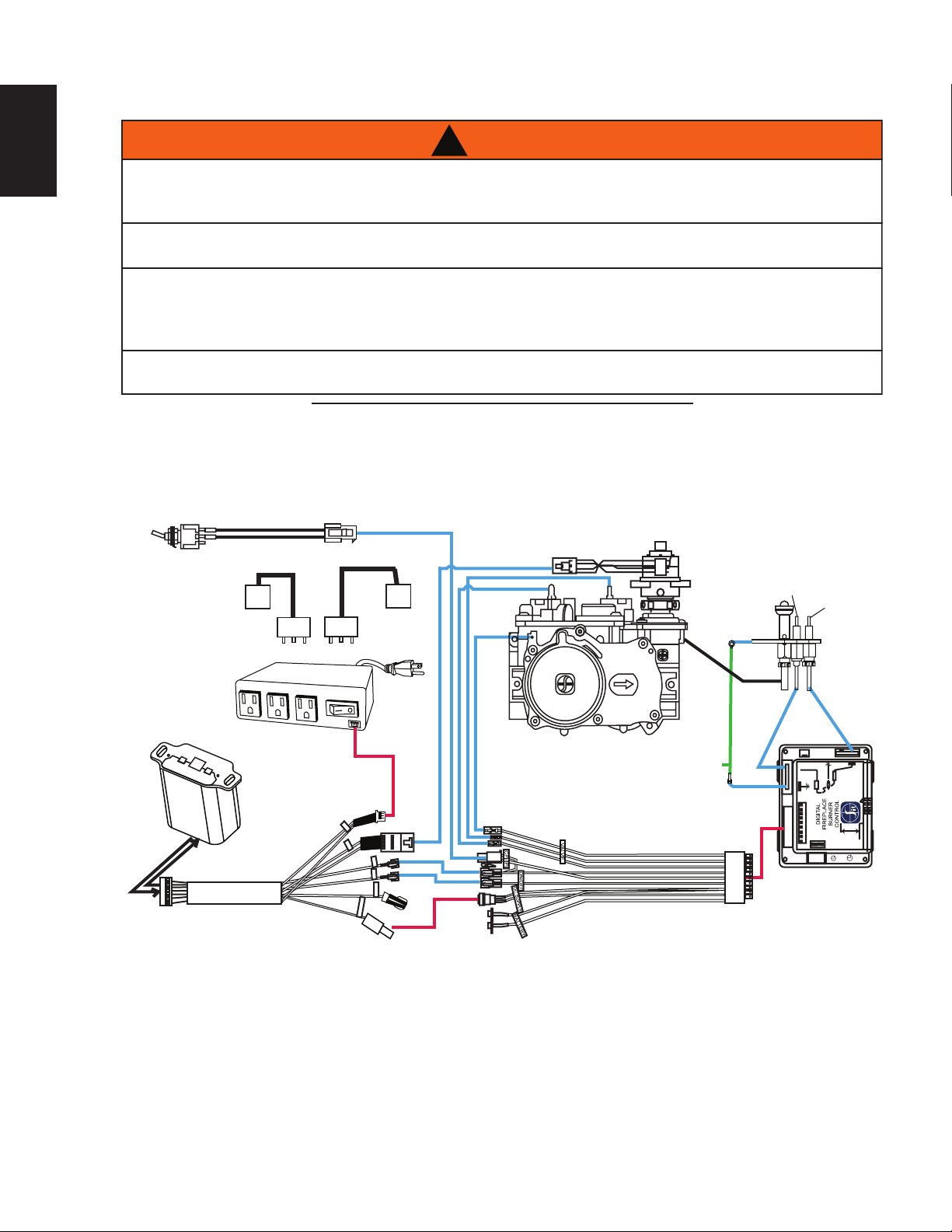
5.1 WIRING DIAGRAM
This appliance comes equipped with a battery back-up. If this back-up is used, install 4 AA batteries (not
supplied) into the receiver.
ACS/IPI Switch
(OPTIONAL)
Fan
(OPTIONAL)
120V OUT
FAN
!
ELECTRICAL CIRCUIT.
THE UNITED STATES.
WITH THE GLASS DOOR OPENED OR REMOVED.
Night Lights
AUX OUT
POWER
69.2_2
Spark Electrode
EI
Pilot
Flame
Sensor
COM
Wire
Harness
Plug
Control Module
Receiver
Wire Harness
Valve
Electronic Modulation
Wire Harness Assembly
Pilot
Ground
Wire
IPI Board
W415-1343 / A / 11.18.16
6.0 OPERATION
WARNING
WARNING:
DO NOT TURN ON IF CHILDREN OR OTHER AT RISK
INDIVIDUALS ARE NEAR THE APPLIANCE. IF YOU DO NOT FOLLOW THESE
INSTRUCTIONS EXACTLY, A FIRE OR EXPLOSION MAY RESULT CAUSING
PROPERTY DAMAGE, PERSONAL INJURY OR LOSS OF LIFE.
INITIAL LIGHTING OF THE PILOT AND MAIN BURNERS MUST BE DONE
WITH THE GLASS DOOR OFF.
DO NOT CONNECT VALVE OR WALL SWITCH TO ELECTRICITY. SEE
INSTALLATION INSTRUCTIONS.
A. THIS APPLIANCE IS EQUIPPED WITH AN IGNITION DEVICE WHICH AUTOMATICALLY
LIGHTS THE PILOT. DO NOT TRY TO LIGHT BY HAND.
B. BEFORE OPERATING, SMELL ALL AROUND THE APPLIANCE AREA FOR GAS AND NEXT TO
THE FLOOR BECAUSE SOME GAS IS HEAVIER THAN AIR AND WILL SETTLE ON THE
FLOOR.
WHAT TO DO IF YOU SMELL GAS:
• TURN OFF ALL GAS TO THE APPLIANCE.
• OPEN WINDOWS.
• DO NOT TRY TO LIGHT ANY APPLIANCE.
• DO NOT TOUCH ANY ELECTRICAL SWITCH; DO NOT USE ANY PHONE IN YOUR
BUILDING.
• IMMEDIATELY CALL YOUR GAS SUPPLIER FROM A NEIGHBOUR’S PHONE. FOLLOW THE
GAS SUPPLIER’S INSTRUCTIONS.
• IF YOU CANNOT REACH YOUR GAS SUPPLIER, CALL THE FIRE DEPARTMENT.
C. DO NOT TRY TO REPAIR ANY PART OF THIS ASSEMBLY. CALL A QUALIFIED SERVICE
TECHNICIAN. FORCE OR ATTEMPTED REPAIR MAY RESULT IN A FIRE OR EXPLOSION.
D. DO NOT USE THIS APPLIANCE IF ANY PART HAS BEEN UNDER WATER. IMMEDIATELY
CALL A QUALIFIED SERVICE TECHNICIAN TO INSPECT THE APPLIANCE AND REPLACE
ANY PART OF THE CONTROL SYSTEM AND ANY GAS CONTROL WHICH HAS BEEN UNDER
WATER.
ATTENTION:
NE PAS ALLUMER SI DES ENFANTS OU D’AUTRES
INDIVIDUS À RISQUE SONT À PROXIMITÉ DU FOYER. QUICONQUE NE
RESPECTE PAS À LA LETTRE LES INSTRUCTIONS DANS LA PRÉSENTE
NOTICE, RISQUE DE DÉCLENCHER UN INCENDIE OU UN EXPLOSION
ENTRAÎNANT DES DOMMAGES, DES BLESSURES OU LA MORT.
L’ALLUMAGE INITIAL DE LA VEILLEUSE ET DU BRÛLEUR PRINCIPAL
DOIT SE FAIRE AVEC LA PORTE VITRÉE ENLEVÉE.
NE RACCORDEZ PAS LA SOUPAPE OU L’INTERRUPTEUR MURAL À
L’ÉLECTRICITÉ. CONSULTEZ LES INSTRUCTIONS D’INSTALLATION.
A. CET APPAREIL EST MUNI D’UN DISPOSITIF D’ALLUMAGE QUI ALLUME
AUTOMATIQUEMENT LA VEILLEUSE. NE TENTEZ PAS D’ALLUMER LA VEILLEUSE
MANUELLEMENT.
B. AVANT DE FAIRE FONCTIONNER, RENIFLEZ TOUT AUTOUR DE L’APPAREIL POUR
DÉCELER UN ODEUR DE GAZ. RENIFLEZ PRÈS DU PLANCHER, CAR CERTAINS GAZ
SONT PLUS LOURDS QUE L’AIR ET PEUVENT S’ACCUMULER AU NIVEAU DU SOL.
QUE FAIRE SI VOUS DÉTECTEZ UNE ODEUR DE GAZ:
• COUPEZ L’ALIMENTATION DE GAZ PRINCIPALE.
• OUVREZ LES FENÊTRES.
• NE PAS TENTER D’ALLUMER D’APPAREIL.
• NE TOUCHEZ À AUCUN INTERRUPTEUR; NE PAS VOUS SERVIR DES TÉLÉPHONES SE
TROUVANT DANS LE BÂTIMENT.
• APPELEZ IMMÉDIATEMENT VOTRE FOURNISSEUR DE GAZ DEPUIS UN VOISIN.
SUIVEZ LES INSTRUCTIONS DU FOURNISSEUR.
• SI VOUS NE POUVEZ REJOINDRE LE FOURNISSEUR APPELEZ LE SERVICE DES
INCENDIES.
C. N’ESSAYEZ PAS DE RÉPARER AUCUNE PIÈCE DE CET ASSEMBLAGE. APPELEZ UN
TECHNICIEN QUALIFIÉ. FORCER OU TENTER DE RÉPARER L’ASSEMBLAGE POURRAIT
CAUSER UN FEU OU UNE EXPLOSION.
D. N’UTILISEZ PAS CET APPAREIL S’IL A ÉTÉ PLONGÉ DANS L’EAU, MÊME
PARTIELLEMENT. FAITES INSPECTER L’APPAREIL PAR UN TECHNICIEN QUALIFIÉ ET
REMPLACEZ TOUTE PARTIE DU SYSTÈME DE CONTRÔLE ET TOUTE COMMANDE QUI
ONT ÉTÉ PLONGÉS DANS L’EAU.
OPERATING INSTRUCTIONS / INSTRUCTIONS D’OPÉRATION
FOR YOUR SAFETY READ BEFORE OPERATING / POUR VOTRE SÉCURITÉ LIRE AVANT DE FAIRE FONCTIONNER
W385-0460 / E
W385-0460 / E
LIGHTING INSTRUCTIONS / INSTRUCTIONS D’ALLUMAGE
1. STOP! READ ALL INFORMATION OF OPERATING AND LIGHTING
INSTRUCTIONS BEFORE PROCEEDING.
2. TURN OFF ELECTRICAL POWER TO THE APPLIANCE.
3. THIS APPLIANCE IS EQUIPPED WITH AN IGNITION DEVICE WHICH
AUTOMATICALLY LIGHTS THE PILOT. DO NOT TRY TO LIGHT THE PILOT
BY HAND.
4. OPEN THE GLASS DOOR.
5. TURN MANUAL SHUTOFF VALVE CLOCKWISE TO OFF.
6. WAIT FIVE (5) MINUTES TO CLEAR OUT ANY GAS. IF YOU SMELL GAS,
INCLUDING NEAR THE FLOOR, STOP! FOLLOW “B” OF THE OPERATING
INSTRUCTIONS. IF YOU DON’T SMELL GAS, GO TO THE NEXT STEP.
7. TURN MANUAL SHUTOFF VALVE COUNTER-CLOCKWISE TO ON.
8. CLOSE THE GLASS DOOR.
9. TURN ON ALL ELECTRICAL POWER TO THE APPLIANCE.
10. TURN ON MAIN BURNER.
1. ARRÊTEZ! LISEZ TOUTES LES INSTRUCTIONS DE
FONCTIONNEMENT ET D’ALLUMAGE AVANT DE CONTINUER.
2. COUPEZ L’ALIMENTATION ÉLECTRIQUE À L’APPAREIL.
3. CET APPAREIL EST MUNI D’UN DISPOSITIF D’ALLUMAGE QUI
ALLUME LA VEILLEUSE AUTOMATIQUEMENT, N’ESSAYEZ PAS
D’ALLUMER LA VEILLEUSE MANUELLEMENT.
4. OUVREZ LA PORTE VITRÉE.
5. TOURNEZ LA SOUPAPE DE SECTIONNEMENT MANUELLE VERS LA
DROITE À « OFF ».
6. ATTENDEZ CINQ (5) MINUTES POUR QUE LE GAZ PUISSE
S’ÉCHAPPER. SI VOUS DÉTECTEZ UNE ODEUR DE GAZ, ARRÊTEZ!
SUIVEZ « B » DANS LES INSTRUCTIONS DE FONCTIONNEMENT.
S’IL N’Y A PAS D’ODEUR DE GAZ, PASSEZ À L’ÉTAPE SUIVANTE.
7. TOURNEZ LA SOUPAPE DE SECTIONNEMENT MANUELLE VERS LA
GAUCHE À « ON ».
8. FERMEZ LA PORTE VITRÉE.
9. RÉTABLISSEZ L’ALIMENTATION ÉLECTRIQUE AU FOYER.
10. ALLUMEZ LE BRÛLEUR PRINCIPAL.
1. TURN OFF ALL ELECTRICAL POWER TO THE APPLIANCE IF SERVICE IS
TO BE PERFORMED.
2. TURN MANUAL SHUTOFF VALVE CLOCKWISE TO OFF. DO NOT
FORCE.
1. COUPEZ L’ALIMENTATION ÉLECTRIQUE AU FOYER SI UN TRAVAIL
D’ENTRETIEN DOIT SE FAIRE.
2. TOURNEZ LA SOUPAPE D’ARRÉT MANUELLE VERS LA DROITE
À « OFF ». NE FORCEZ PAS.
TO TURN OFF GAS / INSTRUCTIONS POUR COUPER LE GAZ
17
!
IF YOU DO NOT FOLLOW THESE INSTRUCTIONS EXACTLY, A FIRE OR EXPLOSION MAY RESULT
CAUSING PROPERTY DAMAGE, PERSONAL INJURY OR LOSS OF LIFE.
ALWAYS LIGHT THE PILOT WHETHER FOR THE FIRST TIME OR IF THE GAS SUPPLY HAS RUN OUT WITH
THE GLASS DOOR OPENED OR REMOVED.
When lit for the first time, the appliance will emit a slight odour for a few hours. This is a normal temporary
condition caused by the "burn-in" of internal paints and lubricants used in the manufacturing process and
will not occur again. Simply open a window to sufficiently ventilate the room. After extended periods of nonoperation such as following a vacation or a warm weather season, the appliance may emit a slight odour for
a few hours. This is caused by dust particles in the heat exchanger burning off. Open a window to sufficiently
ventilate the room.
6.1 OPERATING AND LIGHTING INSTRUCTIONS
EN
W415-1343 / A / 11.18.16
18
WARNING
A. Install 4 AA batteries into the receiver battery bay as indicated on the battery cover (+/-). (Only required
B.
C.
D.
A. Press the ON/OFF key on the transmitter. The transmitter
6.2 XIR3 OPERATION
EN
IF YOU DO NOT FOLLOW THESE INSTRUCTIONS EXACTLY, A FIRE OR EXPLOSION MAY RESULT
CAUSING PROPERTY DAMAGE, PERSONAL INJURY OR LOSS OF LIFE.
ALWAYS LIGHT THE PILOT WHETHER FOR THE FIRST TIME OR IF THE GAS SUPPLY HAS RUN OUT WITH
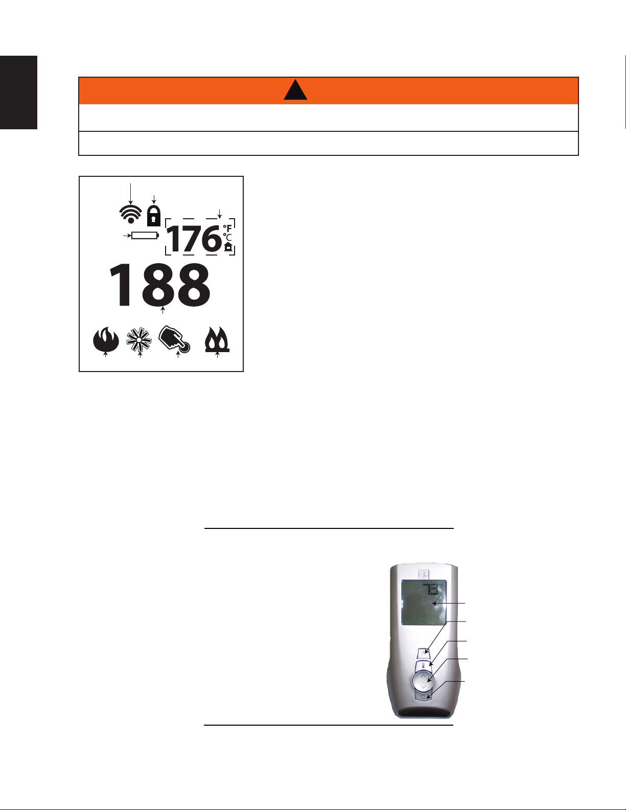
6.2.1 GENERAL TRANSMITTER LAYOUT
TRANSMISSION
CHILD SAFETY
LOCK OUT
LOW BATTERY
ALARM
TEMPERATURE SET POINT/ LEVEL/ STATUS
FANFLAME
AUX. OUTPUT
ROOM
TEMPERATURE
SPLIT VALVE
6.2.2 APPLIANCE OPERATION
!
THE GLASS DOOR OPENED OR REMOVED.
as back up to household electricity).
Place the 3 position slider switch of the receiver in the “Remote” position.
Using the end of a paper clip, or other similar object, insert the end of the paper clip into the hole
marked “PRG” on the receiver front cover. The receiver will “beep” three (3) times to indicate that it is
ready to synchronize with the transmitter.
Install the 3 AAA batteries in the transmitter battery bay, located on the base of the transmitter.
With the batteries already installed in the transmitter, push the “ON” button. The receiver will “beep”
four times to indicate the transmitter’s command is accepted and set to the particular code of that
transmitter. The system is now initialized.
35.2A
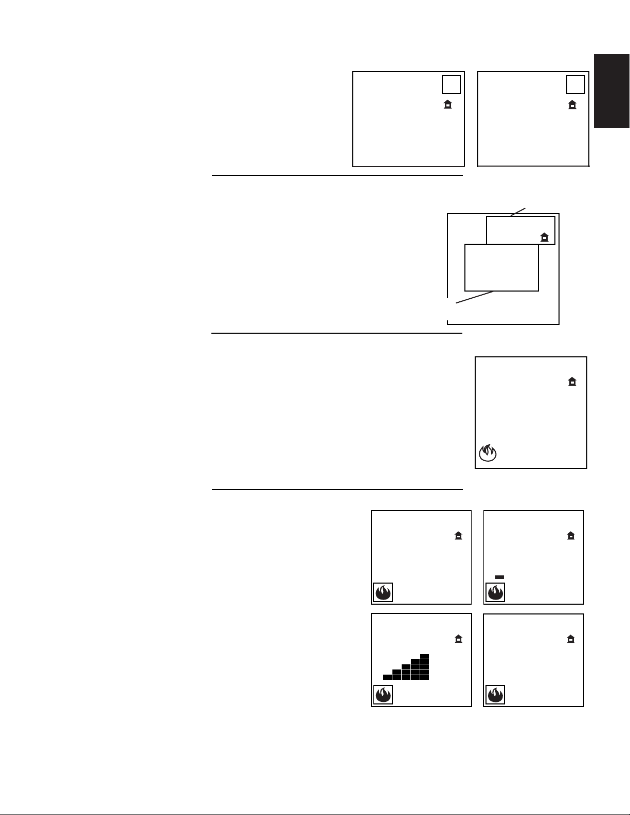
6.2.3 HAND HELD REMOTE OPERATIONS
display will show all active icons on the screen. A single
“beep” from the receiver will confi rm reception of the
command.
BLUE LCD DISPLAY
ON/OFF KEY
TEMPERATURE KEY
UP/DOWN
ARROW KEY
MODE KEY
35.4A
W415-1343 / A / 11.18.16
The remote transmitter can operate as a room thermostat.
35.6
ROOM TEMPERATURE
6.2.4 TEMPERATURE DISPLAY
A. With the system in the “OFF” position, press the
B.
The Smart Thermostat function adjusts the fl ame height according to the difference
between the set temperature and the actual room temperatures. As the room
temperature gets closer to the set point the Smart Function will automatically adjust
the fl ame down.
A.
B.
35.7
The remote control has six (6) fl ame levels. With the
19
Temperature Key and the Mode Key at the same
time to change from degrees F to C.
Look at the LCD screen on the Transmitter to
verify that a C or F is visible to the right of the
Room Temperature display.
6.2.5 ROOM THERMOSTAT
The thermostat can be set to a desired temperature to control the
comfort level in the room.
A. Press the Thermostat Key. The LCD display on the
Transmitter will show that the room is “ON” and the set
temperature is now displayed.
B. To adjust the set temperature, press the Up/Down Arrow
Keys until the desired set temperature is displayed on the
LCD screen of the Transmitter.
6.2.6 SMART THERMOSTAT
°F
73
35.5A
68
SET TEMPERATURE
°C
EN
23
°F
76
°F
Press the thermostat key until the word “SMART” appears to the right of the
temperature bulb graphic.
To adjust the set temperature, press the Up/Down arrow keys until the
desired set temperature is displayed on the LCD screen at the Transmitter.
6.2.7 FLAME HEIGHT
system on and the fl ame level at the maximum, press
the Down Arrow Key once and it will reduce the fl ame
height by one step until the fl ame is turned off.
The Up Arrow Key will increase the fl ame height each
time it is pressed. If the Up Arrow Key is pressed while
the system is on but the fl ame is off, the fl ame will
come on the high position. A single “beep” will confi rm
reception of the command.
76
68
MAX
°F
76
76
OFF
FLAME OFF
°F
76
FLAME AT LEVEL 1
76
Hi
FLAME AT LEVEL 5 FLAME AT “HI” LEVEL 6
°F
°F
W415-1343 / A / 11.18.16
EN
35.10A
The auxiliary function controls the AUX power outlet on
35.12A
The control module offers a remotely actuated 120V AUX
35.16
MAINS VOLTAGE
If the receiver is equipped with batteries they will enable fl ame height control or ON/OFF function to control
programming has been successful once power is restored. During a power failure, if the fi replace was on, the
The life span of the remote batteries depends on various factors: quality of the
35.13A
20
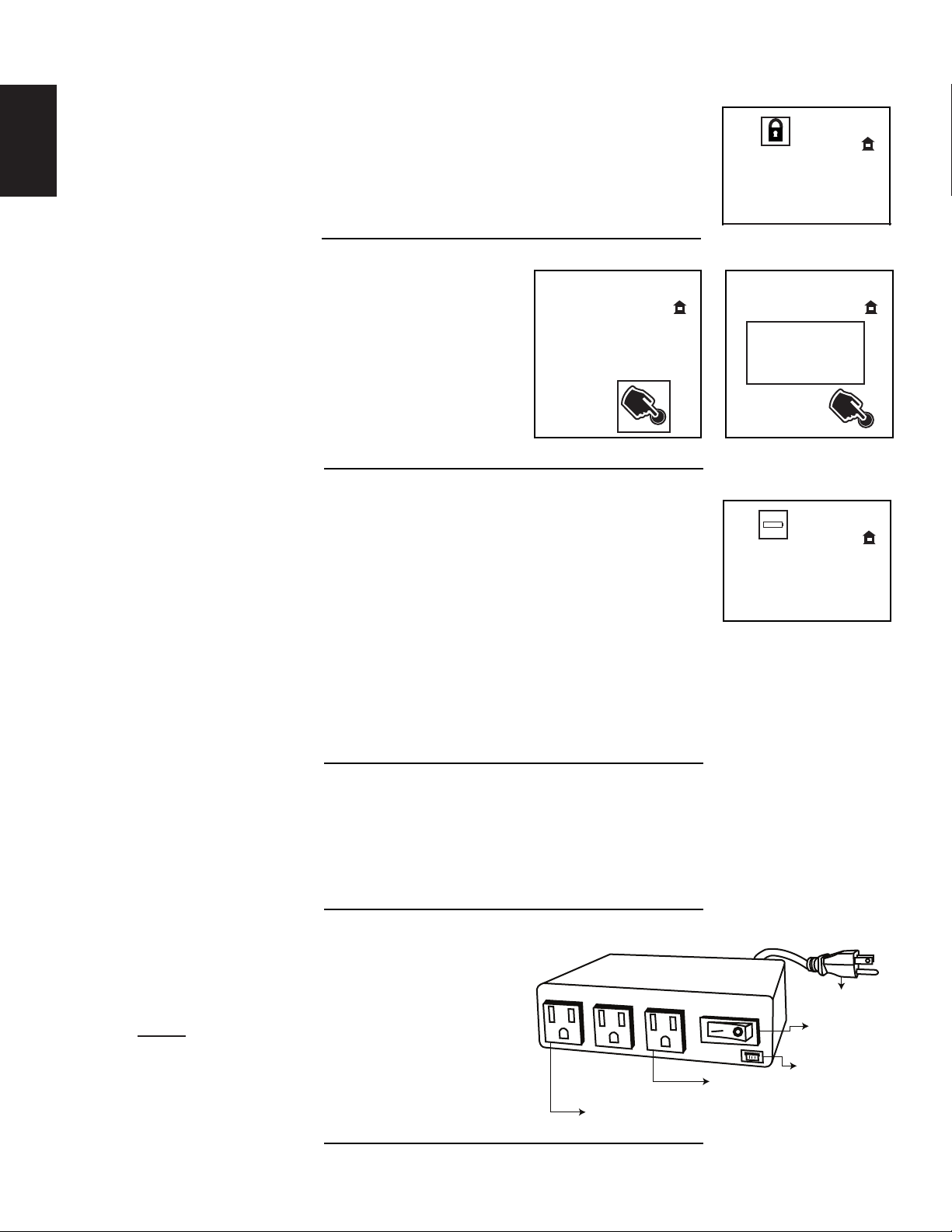
6.2.8 CHILD PROOF FUNCTION
This function will lock the keys to avoid unsupervised operation.
A. Press the MODE and UP keys at the same time.
B. To de-activate this function, press the MODE and UP keys at the same
time.
6.2.9 NIGHT LIGHT
the Control Module which controls the NIGHT LIGHT™.
A. Use the Mode Key to guide you to the AUX icon.
76
°F
76
°F
°F
76
B. Pressing the Up Arrow Key will activate the
NIGHT LIGHT™.
C. Pressing the Down Arrow Key will turn the
NIGHT LIGHT™ off. A single “beep” will confi rm
the reception of the command.
6.2.10 LOW BATTERY / MANUAL BYPASS
batteries, the number of ignitions, etc.
When the transmitter batteries are low, a battery icon will appear on the LCD
display before all battery power is lost. When the batteries are replaced, this icon
will disappear.
When the receiver batteries are low, no “beep” will be emitted from the receiver
when it receives an ON/OFF command. This is an alert for the receiver that there’s
low battery. When the batteries are replaced, the “beep” will be emitted from the
receiver when the ON/OFF key is pressed.
If the batteries of the receiver or transmitter are low, the appliance can be turned on manually by sliding the
three position slider switch on the receiver to the “ON” position. This will bypass the remote control feature
and the appliance main burner will come on if the gas valve is in the “ON” position.
6.2.11 IN THE EVENT OF A POWER FAILURE
OFF
ON
°F
76
the fi replace during a power failure. Refer to “APPLIANCE OPERATION” section when communications
between receiver and transmitter have been lost. The receiver will emit a “beep” sound to confi rm
fl ame height will stay at the setting prior to the failure. If off when the failure occurs and then turned on, the
fl ame height will come on at “HI”. The fl ame height can then be controlled by the remote.
35.14A
6.2.12 CONTROL MODULE
W415-1343 / A / 11.18.16
outlet for the accent lights and a constantly powered
120V outlet.
NOTE: Control module ON/OFF switch should
always be in the “ON” position. If for any reason the
module is turned “OFF”, the components plugged
into the module won’t have power.
CONSTANTLY POWERED
120V OUTLET
120V AUX OUTLET
SUPPLY CORD
MODULE ON/OFF
SWITCH (SHOWN IN
THE ON POSITION)
COMMUNICATION
BUS (3 PIN)
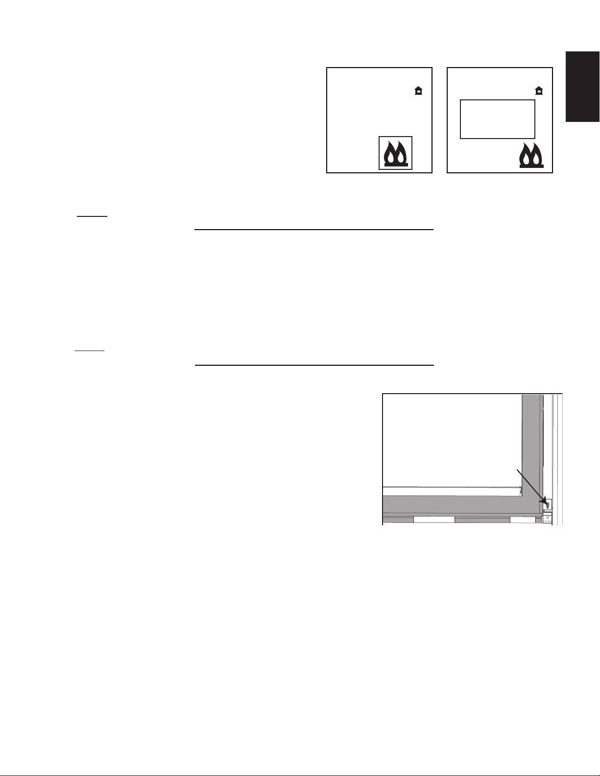
The split fl ow function controls the ability to turn ON/
Your remote system may have a built in timer (in thermostat mode) that enables the blower (if equipped) to
cycle on and off automatically when the burner turns on and off. With the remote control fan speed preset at
the preferred speed, the blower will come on approximately 5 minutes after the main burner comes on and
will shut off approximately 12 minutes after the burner shuts off.
This time delay is designed to maximize the blower distribution of heated air.
If at any time the burner re-ignites before the twelve minutes are over, the fan will continue to run.
NOTE:
remote control.
6.2.13 SPLIT FLOW VALVE
OFF a second burner.
A. Use the mode key to guide you to the split fl ow
function.
B. Pressing the up arrow key will activate the
second burner.
C. Pressing the down arrow key will deactivate the
second burner. A single “beep” will confi rm the reception of the command.
NOTE:Thereisnowaytomodulatetheflameheightsseparately.
6.2.14 TIMED BLOWER
°F
76
OFF
ON
35.17A
76
21
°F
EN
At any time in the sequence, the blower (if equipped) can be manually turned on/off using the
6.3 ANTI CONDENSATION CONTROL SWITCH
This appliance has the option to go from an electronic intermittent
pilot ignition to a standing pilot for cold climates.
35.19B
RIGHT SIDE OF
DOOR FRAME
(OPERATING SIDE)
ANTI CONDENSATION
CONTROL SWITCH
W415-1343 / A / 11.18.16
22
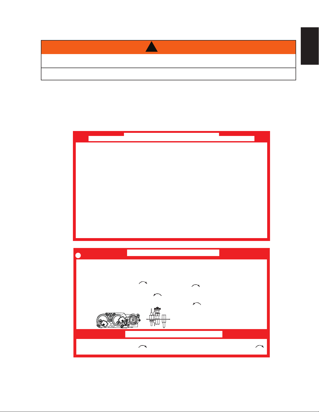
Adjust the pilot screw to provide properly sized fl ame. Turn in a
This appliance has an air shutter that has been factory set open according
SHUTTER
7.0 ADJUSTMENTS
7.1 PILOT BURNER ADJUSTMENT
EN
clockwise direction to reduce the gas fl ow.
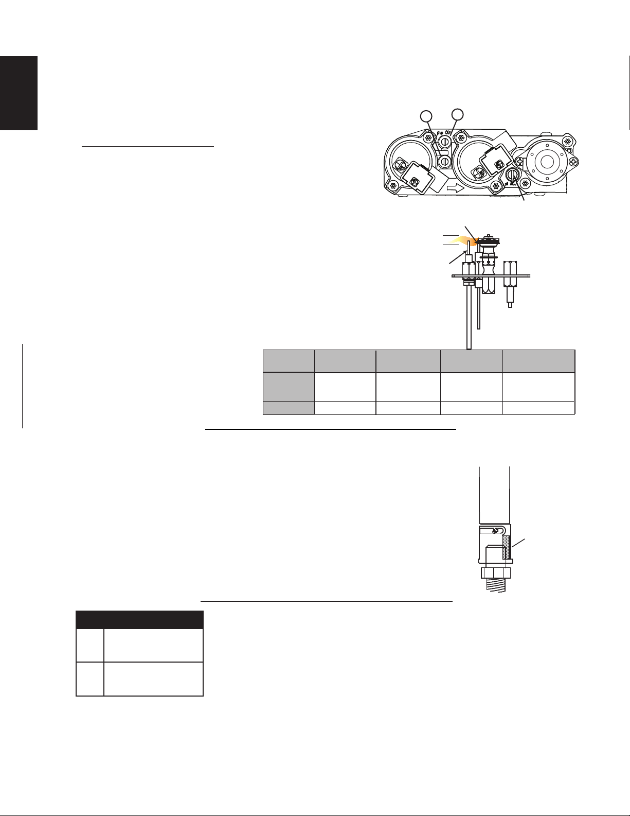
Check Pressure Readings:
Inlet pressure can be checked by turning screw (A) counterclockwise 2 or 3 turns and then placing pressure gauge tubing
over the test point. Gauge should read as described on the chart
below. Check pressure with main burner operating on “HI”.
Outlet pressure can be checked the same as above using
screw (B). Gauge should read as described on the chart
below. Check pressure with main burner operating on “HI”.
AFTER TAKING PRESSURE READINGS, BE SURE TO
TURN SCREWS CLOCKWISE FIRMLY TO RESEAL. DO
NOT OVERTORQUE.
Leak test with a soap and water solution.
A
ELECTRODE
3/8” - 1/2”
(9.5mm - 12.7mm)
FLAME
SENSOR
B
PILOT SCREW
PILOT
BURNER
Prior to pilot adjustment, ensure that the pilot assembly
has not been painted. If overspray or painting of the pilot
assembly has occurred remove the paint from the pilot
assembly, or replace. Fine emery
Pressure
cloth or a synthetic scrub pad (such as
Scotch-Brite™) can be used to remove
the paint from the pilot hood, electrode
and fl ame sensor.
Inlet
Outlet
*Maximum inlet pressure not to exceeed 13”.
7.2 VENTURI ADJUSTMENT
to the chart below:
Regardless of venturi orientation, closing the air shutter will cause a more
yellow flame, but can lead to carbonization. Opening the air shutter will
cause a more blue flame, but can cause flame lifting from the burner ports.
The flame may not appear yellow immediately; allow 15 to 30 minutes for
the final flame colour to be established.
AIR SHUTTER ADJUSTMENT MUST ONLY BE DONE BY A QUALIFIED
INSTALLER!
Natural Gas
(inches)
*7"
(MIN. 4.5”)
3.5"
Natural Gas
(millibars)
17.4mb
(MIN. 11.2mb)
8.7mb
Propane
(inches)
13"
(MIN. 11")
39.1E
VENTURI
BURNER
ORIFICE
49.1
FLAME MUST ENVELOP
UPPER 3/8” (9.5mm) TO 1/2”
(12.7mm) OF FLAME SENSOR
Propane
(millibars)
32.4mb
(MIN. 27.4mb)
10"
24.9mb
AIR
OPENING
XIR3
NG
W415-1343 / A / 11.18.16
P
F 1/8"(3.2mm)
R 5/16"(8mm)
F 1/2"(12.7mm)
R 3/8"(9.5mm)
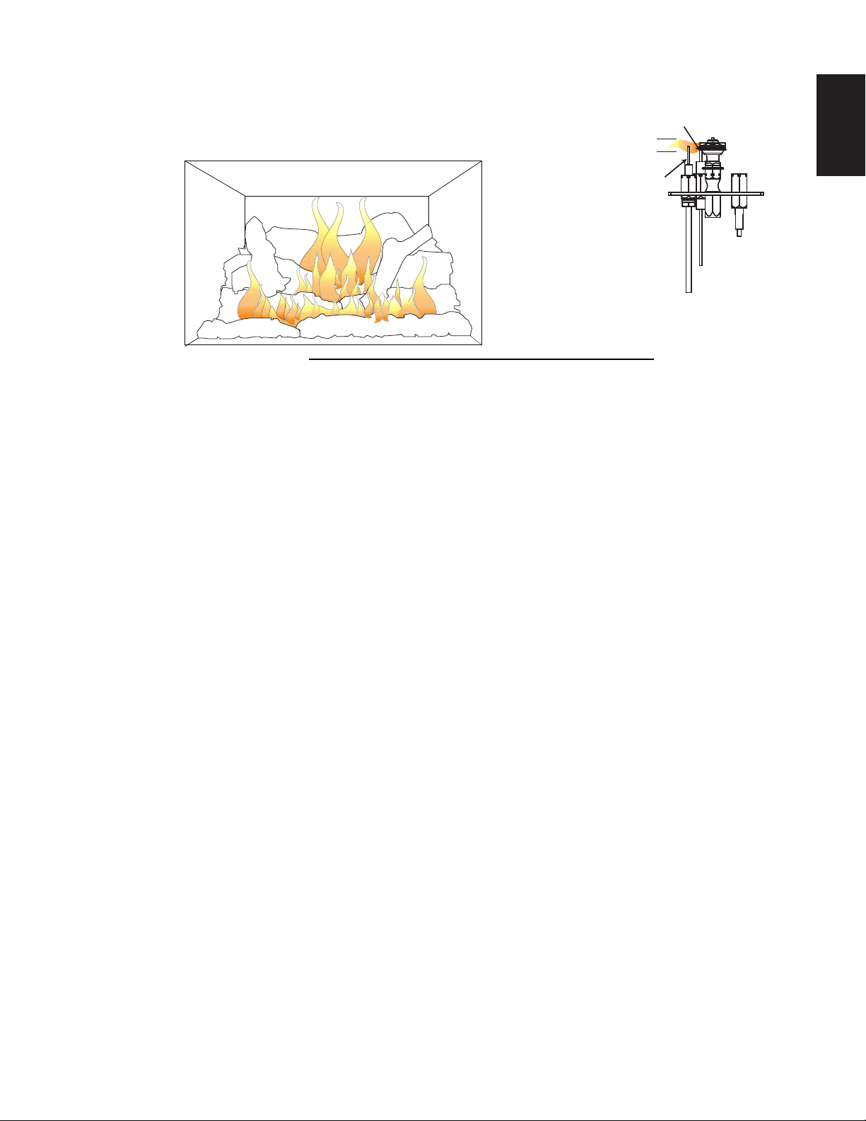
7.3 FLAME CHARACTERISTICS
It is important to periodically perform a visual check of the pilot
and burner fl ames. Compare them to the illustration provided. If
any fl ames appear abnormal, call a service person.
FLAME MUST ENVELOP
UPPER 3/8” (9.5mm) TO 1/2”
(12.7mm) OF FLAME SENSOR
PILOT
BURNER
ELECTRODE
FLAME
SENSOR
3/8” - 1/2”
(9.5mm - 12.7mm)
54.1B
23
EN
W415-1343 / A / 11.18.16
24
!
WARNING
THE FIREBOX BECOMES VERY HOT DURING OPERATION. LET THE APPLIANCE COOL
COMPLETELY OR WEAR HEAT RESISTANT GLOVES BEFORE CONDUCTING SERVICE.
NEVER VACUUM HOT EMBERS.
DO NOT PAINT THE PILOT ASSEMBLY.
• This appliance will require maintenance which should be planned on an annual basis.
• Service should include cleaning, battery replacement, venting inspection and inspection of the burner,
media and fi rebox. Refer to the door removal section and remove the door as instructed.
• Carefully remove media if necessary (logs, glass, brick panels etc).
• Using a vacuum with a soft brush attachment, gently remove any dirt, debris or carbon build up from the
logs, fi rebox and burner. For glass media, follow the installation instructions for pre-cleaning.
• Also gently remove any build-up on the pilot assembly including, if equipped; thermopile, thermocouple,
fl ame sensor and igniter.
NOTE: Clean fl ame sensor using a fi ne emery cloth or a synthetic scrub pad
(such as Scotch-Brite™) to remove any oxides.
Clean the pilot assembly using a vacuum with a soft
brush attachment.
It is important that the pilot assembly is not painted.
• Inspect all accessible gaskets and replace as required.
• Access the blower, if equipped and clean using a soft brush and vacuum.
• Re-assemble the various components in reverse order.
appliance area must be kept clear and free of combustible materials, gasoline or other fl ammable vapors and
TURN OFF THE GAS AND ELECTRICAL POWER BEFORE SERVICING THE APPLIANCE.
APPLIANCE MAY BE HOT, DO NOT SERVICE UNTIL APPLIANCE HAS COOLED.
DO NOT USE ABRASIVE CLEANERS.
DO NOT PAINT THE PILOT ASSEMBLY.
MAINTENANCE
MAINTENANCE
MAINTENANCE
!
WARNING
8.0 MAINTENANCE
EN
This appliance and its venting system should be inspected before use and at least annually by a qualifi ed
service person. The following suggested checks should be performed by a qualifi ed technician. The
liquids. The fl ow of combustion and ventilation air must not be obstructed.
CAUTION: Label all wires prior to disconnection when servicing controls. Wiring errors can cause improper
and dangerous operation. Verify proper operation after servicing.
A. In order to properly clean the burner and pilot assembly, remove the logs, rocks and/or glass to
expose both assemblies.
B. Keep the control compartment, media, burner, air shutter opening and the area surrounding the logs
clean by vacuuming or brushing, at least once a year.
C. Check to see that all burner ports are burning. Clean out any of the ports which may not be burning
or are not burning properly.
D. Check to see that the pilot fl ame is large enough to engulf the fl ame sensor and/or thermocouple /
thermopile as well as reaches the burner.
E. Replace the cleaned logs, rocks or glass. Failure to properly position the media may cause carbon
which can be distributed inside of fi rebox and on exterior surfaces surrounding vent termination.
F. Check to see that the main burner ignites completely on all openings when turned on. A 5 to 10
second total light-up period is satisfactory. Service as required.
G. Check that the gasketing on the sides, top and bottom of the door is not broken or missing. Replace
if necessary.
H. If for any reason the vent air intake system is disassembled, re-install and re-seal per the instructions
provided for the initial installation.
I. Cleaning the safety barrier may be necessary due to excessive lint / dust from carpeting, pets, etc.
simply vacuum using the brush attachment.
J. Ensure the relief system performs effectively. Check that the gasket is not worn or damaged. Replace
if necessary.
40.1E
8.1 ANNUAL MAINTENANCE
W415-1343 / A / 11.18.16

8.2 CARE OF GLASS
5.1A
If the appliance is equipped with plated parts, you must clean fi ngerprints or other marks from the plated
WARNING
37.1E
!
WARNING
THE FIREBOX BECOMES VERY HOT DURING OPERATION. LET THE APPLIANCE COOL
COMPLETELY OR WEAR HEAT RESISTANT GLOVES BEFORE CONDUCTING SERVICE.
NEVER VACUUM HOT EMBERS.
DO NOT PAINT THE PILOT ASSEMBLY.
• This appliance will require maintenance which should be planned on an annual basis.
• Service should include cleaning, battery replacement, venting inspection and inspection of the burner,
media and fi rebox. Refer to the door removal section and remove the door as instructed.
• Carefully remove media if necessary (logs, glass, brick panels etc).
• Using a vacuum with a soft brush attachment, gently remove any dirt, debris or carbon build up from the
logs, fi rebox and burner. For glass media, follow the installation instructions for pre-cleaning.
• Also gently remove any build-up on the pilot assembly including, if equipped; thermopile, thermocouple,
fl ame sensor and igniter.
NOTE: Clean fl ame sensor using a fi ne emery cloth or a synthetic scrub pad
(such as Scotch-Brite™) to remove any oxides.
Clean the pilot assembly using a vacuum with a soft
brush attachment.
It is important that the pilot assembly is not painted.
• Inspect all accessible gaskets and replace as required.
• Access the blower, if equipped and clean using a soft brush and vacuum.
• Re-assemble the various components in reverse order.
• Inspect the relief system. The appliance relieves through the main glass door or through the fl aps on the
fi rebox top. Ensure they open freely, and close sealed.
• Check the gas control valve pilot and Hi / Lo knobs move freely (if equipped) – replace if any stiffness in
movement is experienced.
• Check for gas leaks on all gas connections up and downstream from the gas valve including the pilot
tube connections.
DO NOT CLEAN GLASS WHEN HOT! DO NOT USE
ABRASIVE CLEANERS TO CLEAN GLASS.
Buff lightly with a clean dry soft cloth. Clean both sides
of the glass after the fi rst 10 hours of operation with a
recommended fi replace glass cleaner. Do not use an
ammonia-based fi replace glass cleaner. Thereafter clean
as required. If the glass is not kept clean permanent
discoloration and / or blemishes may result.
This appliance is factory equipped with 5mm ceramic glass. Use only replacement parts as supplied by the
appliance manufacturer. DO NOT SUBSTITUTE MATERIALS.
8.3 CARE OF PLATED PARTS
!
WARNING
HOT GLASS WILL
CAUSE BURNS.
DO NOT TOUCH GLASS
UNTIL COOLED.
NEVER ALLOW CHILDREN
TO TOUCH GLASS.
5.5.1A
25
EN
surfaces before operating the appliance for the fi rst time. Use a glass cleaner or vinegar and towel to clean.
If not cleaned properly before operating for the fi rst time, the marks can cause permanent blemishes on the
plating. After the plating is cured, the fi ngerprints and oils will not affect the fi nish and little maintenance
is required, just wipe clean as needed. Prolonged high temperature burning with the door ajar may cause
discolouration on plated parts.
NOTE: The protective wrap on plated parts is best removed when the assembly is at room temperature
but this can be improved if the assembly is warmed, using a hair dryer or similar heat source.
6.1
8.4 DOOR GLASS REPLACEMENT
GLASS MAY BE HOT, DO NOT TOUCH GLASS UNTIL COOLED.
CARE MUST BE TAKEN WHEN REMOVING AND DISPOSING OF ANY BROKEN DOOR GLASS OR
DAMAGED COMPONENTS. BE SURE TO VACUUM UP ANY BROKEN GLASS FROM INSIDE THE
DO NOT STRIKE, SLAM OR SCRATCH GLASS. DO NOT OPERATE APPLIANCE WITH GLASS
Replacement glass/frame assembly shall be replaced as a complete unit as supplied by the
appliance manufacturer.
NOTE: Care must be taken when removing and disposing of any broken glass or damaged
components. Be sure to vacuum up any broken glass from inside the appliance before operation.
DO NOT USE SUBSTITUTE MATERIALS.
APPLIANCE BEFORE OPERATION.
REMOVED, CRACKED, BROKEN OR SCRATCHED.
!
56.1C
W415-1343 / A / 11.18.16
26
WARNING
ACCESS PLATE
EN
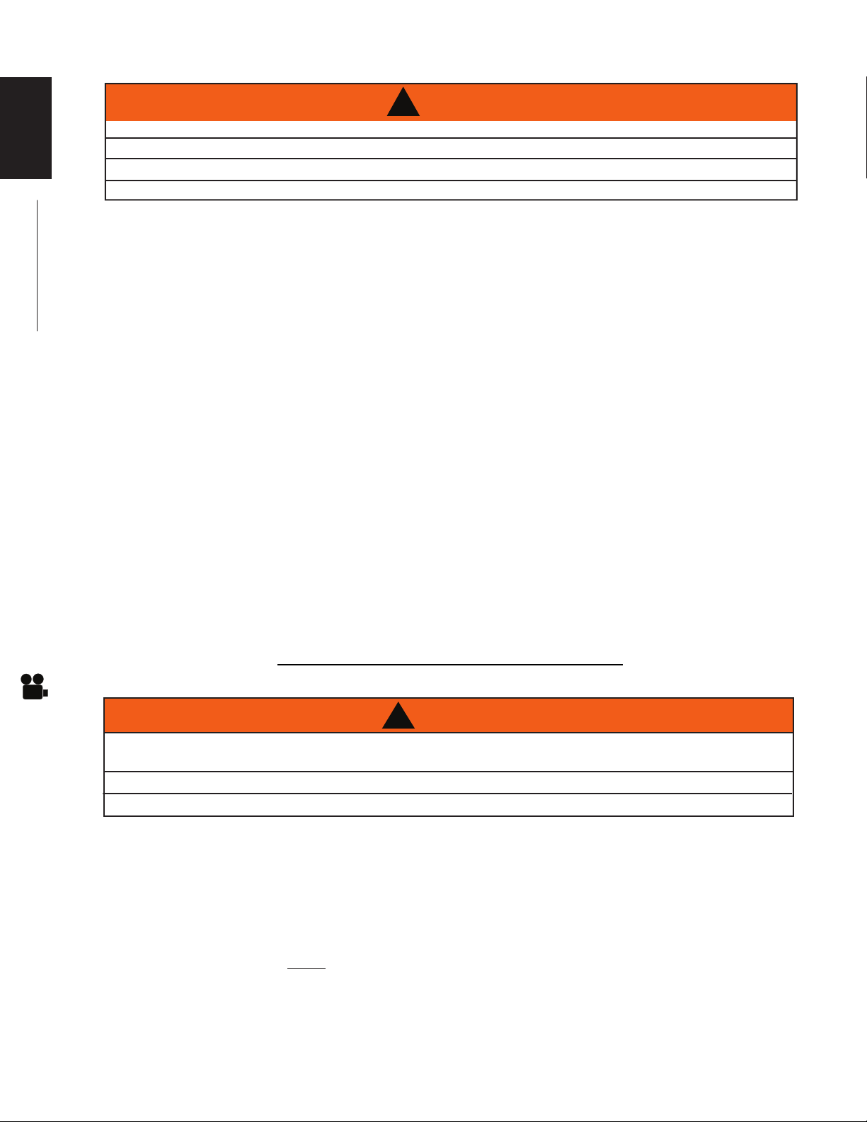
8.5 BURNER REMOVAL
A. Remove the glass door, see "DOOR REMOVAL AND INSTALLATION" section. Remove the
logs, see "FINISHING" section.
B. Remove the 5 screws that secure
the rear log support in place. Lift the
support out.
C. Remove the 4 screws holding the
rear burner tube and lift it up and
out.
D. Remove the 5 screws that secure
the front burner support in place
and lift the support up and out.
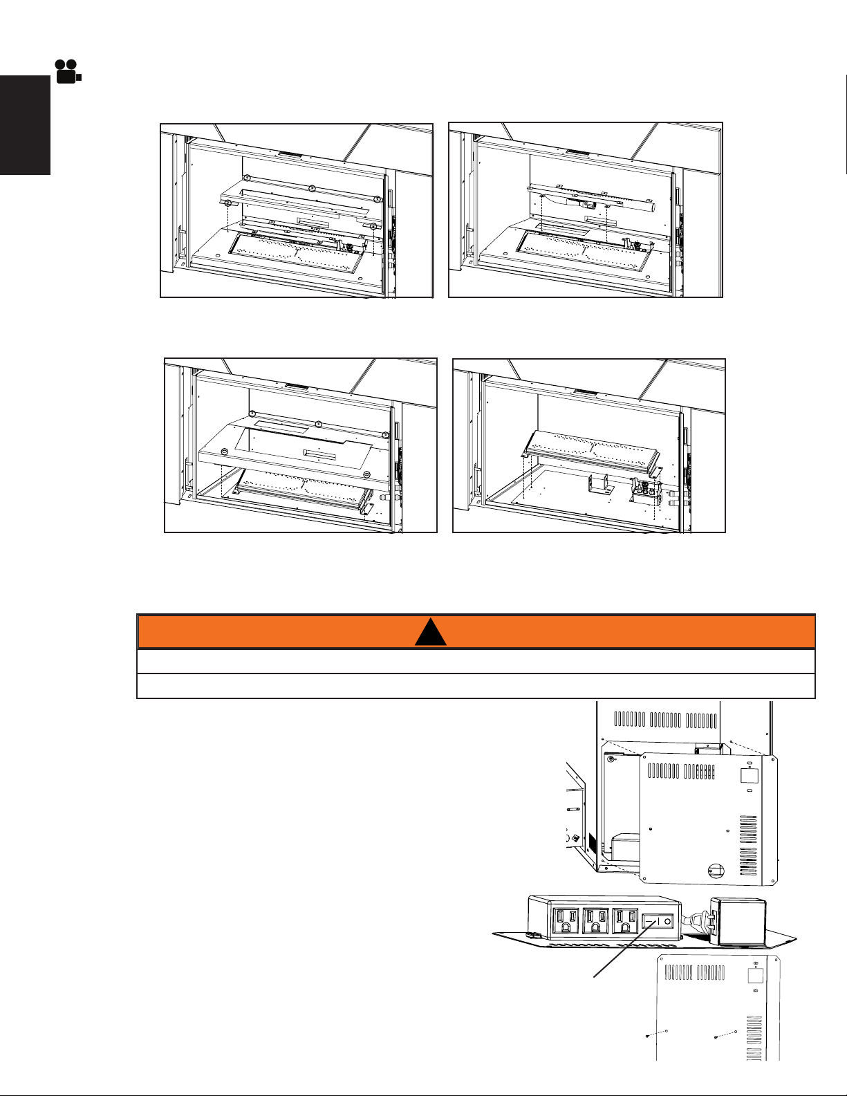
8.6 FCM REPLACEMENT
TURN OFF THE GAS AND ELECTRICAL POWER BEFORE SERVICING THE APPLIANCE.
THE APPLIANCE MAY BE HOT. DO NOT SERVICE APPLIANCE UNTIL IT HAS COOLED.
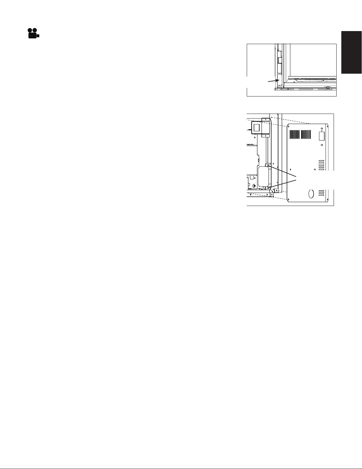
A. To access the fan control module, you must first pull out
the appliance, allowing enough room to access the left
access plate.
B. Remove the screws holding the access plate in position.
C. Unplug the fan control module from the
junction box. Unplug the night light plug and
blower plug (if applicable) from the
fan control module.
D. Remove the 2 screws securing the fan control to
the access plate and replace. NOTE: Ensure
that the ON/OFF switch is in the ON (-) position.
E. Reinstall the plugs and access plate
E. Remove the 4 screws that secure
the front burner support in place
and lift the burner up and out.
!
W415-1343 / A / 11.18.16
ON/OFF
SWITCH
 Loading...