

Page 1
INSTALLER: LEAVE THIS MANUAL WITH THE APPLIANCE.
CONSUMER: RETAIN THIS MANUAL FOR FUTURE REFERENCE.
DANGER
SAFETY BARRIER
NEVER LEAVE CHILDREN OR OTHER AT RISK INDIVIDUALS ALONE WITH THE APPLIANCE
INSTALLATION AND
EN
OPERATING INSTRUCTIONS
CERTIFIED UNDER CANADIAN AND UNITED STATES STANDARD: CSA 2.22, ANSI Z21.50 VENTED GAS FIREPLACES
CERTIFIED FOR CANADA AND UNITED STATES USING ANSI/CSA METHODS.
SAFETY INFORMATION
!
WARNING
If the information in these instructions
are not followed exactly, a fi re or
explosion may result causing property
damage, personal injury or loss of life.
- Do not store or use gasoline or other fl ammable
vapors and liquids in the vicinity of this or any
other appliance.
- WHAT TO DO IF YOU SMELL GAS:
• Do not try to light any appliance.
• Do not touch any electrical switch; do not use
any phone in your building.
• Immediately call your gas supplier from a
neighbour’s phone. Follow the gas supplier’s
instructions.
• If you cannot reach your gas supplier, call the
fi re department.
- Installation and service must be performed by a
qualifi ed installer, service agency or the supplier.
This appliance may be installed in an aftermarket,
permanently located, manufactured home (USA
only) or mobile home, where not prohibited by
local codes.
This appliance is only for use with the type of gas
indicated on the rating plate. This appliance is
not convertible for use with other gases, unless a
certifi ed kit is used.
Decorative Product: Not for use as a heating appliance.
FR
PG
53
WHD48N
NATURAL GAS
WHD48P
PROPANE
!
HOT GLASS WILL CAUSE
BURNS.
DO NOT TOUCH GLASS UNTIL
COOLED.
NEVER ALLOW CHILDREN TO
TOUCH GLASS.
A barrier designed to reduce the risk of burns from
the hot viewing glass is provided with this appliance
and shall be installed for the protection of children
and other at-risk individuals.
Wolf Steel Ltd., 24 Napoleon Rd., Barrie, ON, L4M 0G8 Canada /
Phone (705)721-1212 • Fax (705)720-9081 • www.napoleon replaces.com • hearth@napoleonproducts.com
$10.00
103 Miller Drive, Crittenden, Kentucky, USA, 41030
1.28F
W415-1606 / 09.09.16
Page 2

EN
2
TABLE OF CONTENTS
1.0 INSTALLATION OVERVIEW 3
2.0 INTRODUCTION 4
2.1 DIMENSIONS 5
2.2 GENERAL INSTRUCTIONS 6
2.3 GENERAL INFORMATION 7
2.4 RATING PLATE INFORMATION 7
3.0 VENTING 8
3.1 VENTING LENGTHS AND COMPONENTS 9
3.2 TYPICAL VENT INSTALLATION 10
3.3 SPECIAL VENT INSTALLATIONS 10
3.3.1 PERISCOPE TERMINATION 10
3.4 VENT TERMINAL CLEARANCES 11
3.5 VENTING APPLICATION FLOW CHART 12
3.6 DEFINITIONS 12
3.7 ELBOW VENT LENGTH VALUES 12
3.8 HORIZONTAL TERMINATION 13
3.9 VERTICAL TERMINATION 15
4.0 INSTALLATION 17
4.1 WALL AND CEILING PROTECTION 17
4.2 MOUNTING PLATE INSTALLATION 18
4.3 USING FLEXIBLE VENT COMPONENTS 19
4.3.1 APPLIANCE VENT CONNECTION 19
4.3.2 VERTICAL INSTALLATION 20
4.3.3 HORIZONTAL AIR TERMINAL INSTALLATION 20
4.3.4 VERTICAL AIR TERMINAL INSTALLATION (FLEXIBLE) 21
4.3.5 HORIZONTAL AIR TERMINAL INSTALLATION 22
4.3.6 EXTENDED HORIZONTAL AND CORNER TERMINAL INSTALLATION 22
4.4 MOUNTING THE WHD48 23
4.5 GAS INSTALLATION 24
4.6 MOBILE HOME 24
4.7 MINIMUM CLEARANCE TO COMBUSTIBLES AND NON-COMBUSTIBLES 25
5.0 FINISHING 26
5.1 HOUSING PANEL INSTALLATION 26
5.2 DOOR REMOVAL / INSTALLATION 27
5.3 GLASS MEDIA 27
5.4 SURROUND INSTALLATION / REMOVAL 28
5.5 LOGO PLACEMENT 28
6.0 OPTIONAL INSTALLATION 29
6.1 RECEIVER LOCATION/WIRING 29
7.0 ELECTRICAL INFORMATION 30
7.1 HARD WIRING CONNECTION 30
7.2 WIRING DIAGRAM 30
8.0 OPERATION 31
8.1 OPERATING INSTRUCTIONS 31
8.2 LIGHTING INSTRUCTIONS 31
8.3 GENERAL TRANSMITTER LAYOUT 32
8.4 INITIALIZING THE TRANSMITTER/BATTERY HOLDER FOR THE FIRST TIME 33
8.5 TEMPERATURE DISPLAY 33
8.6 FLAME HEIGHT TIME 33
8.7 LED ON/OFF LIGHT CONTROL 34
8.8 CONTINUOUS PILOT / INTERMITTENT PILOT (CPI / IPI) SELECTION 35
8.9 CHILD PROOF FUNCTION 35
8.10 LOW BATTERY / MANUAL BYPASS 35
8.11 IN THE EVENT OF A POWER FAILURE 35
8.12 TIMED BLOWER 36
8.13 MANUAL OPERATION 36
9.0 ADJUSTMENTS 37
9.1 PILOT BURNER ADJUSTMENT 37
9.2 VENTURI ADJUSTMENT 37
9.3 FLAME CHARACTERISTICS 38
10.0 MAINTENANCE 39
10.1 ANNUAL MAINTENANCE 40
10.2 CARE OF GLASS 40
10.3 CARE OF PLATED PARTS 40
10.4 DOOR GLASS REPLACEMENT 41
11.0 REPLACEMENTS 42
11.1 OVERVIEW 43
11.2 VALVE TRAIN ASSEMBLY 44
12.0 ACCESSORIES 45
13.0 TROUBLESHOOTING 46
14.0 WARRANTY 48
15.0 SERVICE HISTORY 49
16.0 NOTES 50
NOTE: Changes, other than editorial, are denoted by a line in the margin.
W415-1606 / 09.09.16
Page 3

754321
1.0 INSTALLATION OVERVIEW
3
Mantel, see
“MINIMUM
MANTEL
CLEARANCES”
section.
Venting, see
“VENTING”
section.
EN
Side Wall, see
“MINIMUM
CLEARANCES TO
COMBUSTIBLES”
section.
Rating plate, see “RATING
PLATE INFORMATION”
section.
W415-1606 / 09.09.16
Page 4

4
!
WARNING
2.0 INTRODUCTION
EN
• THIS APPLIANCE IS HOT WHEN OPERATED AND CAN CAUSE SEVERE BURNS IF CONTACTED.
• ANY CHANGES OR ALTERATIONS TO THIS APPLIANCE OR ITS CONTROLS CAN BE DANGEROUS AND IS
PROHIBITED.
• Do not operate appliance before reading and understanding operating instructions. Failure to operate appliance
according to operating instructions could cause fi re or injury.
• Risk of fi re or asphyxiation do not operate appliance with fi xed glass removed.
• Do not connect 110 volts to the control valve.
• Risk of burns. The appliance should be turned off and cooled before servicing.
• Do not install damaged, incomplete or substitute components.
• Risk of cuts and abrasions. Wear protective gloves and safety glasses during installation. Sheet metal edges may
be sharp.
• Do not burn wood or other materials in this appliance.
• Children and adults should be alerted to the hazards of high surface temperature and should stay away to
avoid burns or clothing ignition.
• Young children should be carefully supervised when they are in the same room as the appliance.
Toddlers, young children and others may be susceptible to accidental contact burns. A physical barrier
is recommended if there are at risk individuals in the house. To restrict access to an appliance, install an
adjustable safety gate to keep toddlers, young children and other at risk individuals out of the room and
away from hot surfaces.
• Clothing or other fl ammable material should not be placed on or near the appliance.
• Due to high temperatures, the appliance should be located out of traffi c and away from furniture and
draperies.
• Ensure you have incorporated adequate safety measure to protect infants/toddlers from touching hot surfaces.
• Even after the appliance is out, the glass and/or screen will remain hot for an extended period of time.
• Check with your local hearth specialty dealer for safety screens and hearth guards to protect children from hot
surfaces. These screens and guards must be fastened to the fl oor.
• Any safety screen, guard or barrier removed for servicing the appliance, must be replaced prior to operating
the appliance.
• The appliance is a vented gas-fi red appliance. Do not burn wood or other materials in the appliance
• It is imperative that the control compartments, burners and circulating blower and its passageway in the appliance
and venting system are kept clean. The appliance and its venting system should be inspected before use and at
least annually by a qualifi ed service person. More frequent cleaning may be required due to excessive lint from
carpeting, bedding material, etc. The appliance area must be kept clear and free from combustible materials,
gasoline and other fl ammable vapors and liquids.
• Under no circumstances should this appliance be modifi ed.
• This appliance must not be connected to a chimney fl ue pipe serving a separate solid fuel burning appliance.
• Do not use this appliance if any part has been under water. Immediately call a qualifi ed service technician to
inspect the appliance and to replace any part of the control system and any gas control which has been under
water.
• Do not operate the appliance with the glass door removed, cracked or broken. Replacement of the glass should be
done by a licensed or qualifi ed service person.
• Do not strike or slam shut the appliance glass door.
• When equipped with pressure relief doors, they must be kept closed while the appliance is operating to prevent
exhaust fumes containing carbon monoxide, from entering into the home. Temperatures of the exhaust escaping
through these openings can also cause the surrounding combustible materials to overheat and catch fi re.
• Only doors / optional fronts certifi ed with the appliance are to be installed on the appliance.
• Keep the packaging material out of reach of children and dispose of the material in a safe manner. As with all
plastic bags, these are not toys and should be kept away from children and infants.
• As with any combustion appliance, we recommend having your appliance regularly inspected and serviced as well
as having a Carbon Monoxide Detector installed in the same area to defend you and your family against Carbon
Monoxide.
• Ensure clearances to combustibles are maintained when building a mantel or shelves above the appliance.
Elevated temperatures on the wall or in the air above the appliance can cause melting, discolouration or damage of
decorations, a T.V. or other electronic components.
• A barrier designed to reduce the risk of burns from the hot viewing glass is provided with this appliance and
shall be installed.
• If the barrier becomes damaged, the barrier shall be replaced with the manufacturer’s barrier for this
appliance.
• Installation and repair should be done by a qualifi ed service person. The appliance should be inspected
before use and at least annually by a professional service person. More frequent cleaning may be required
due to excessive lint from carpeting, bedding material, etc. It is imperative that control compartments,
burners and circulating air passageways of the appliance be kept clean.
3.2C
W415-1606 / 09.09.16
Page 5
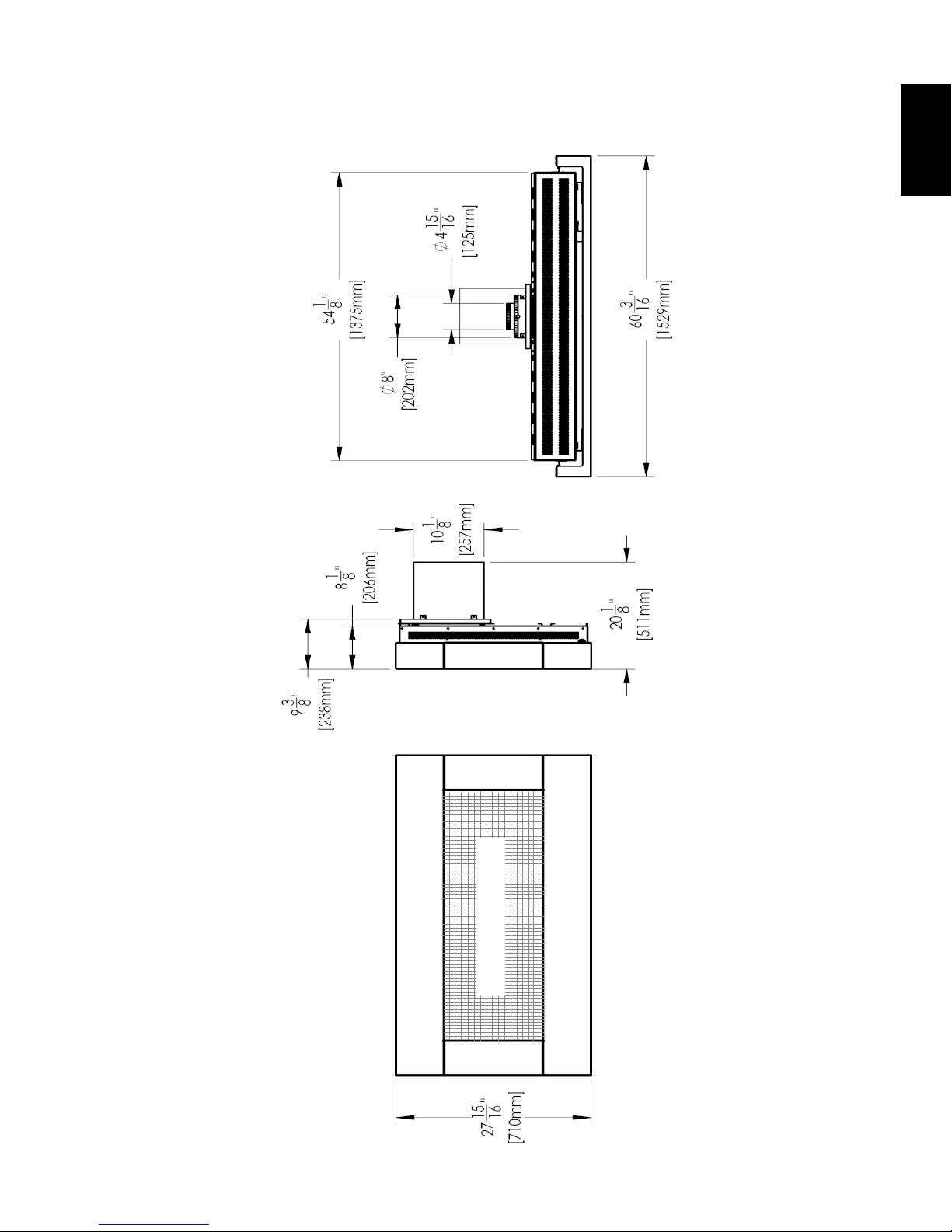
2.1 DIMENSIONS
5
EN
SAFETY BARRIER
W415-1606 / 09.09.16
Page 6
6
THIS GAS APPLIANCE SHOULD BE INSTALLED AND SERVICED BY A QUALIFIED INSTALLER
conform with local codes. Installation practices vary from region to region and it is important to know the
specifi cs that apply to your area, for example in Massachusetts State:
•
•
•
•
•
•
The installation must conform with local codes or, in
absence of local codes, the National Gas and Propane
Installation Code CSA B149.1 in Canada, or the National
Fuel Gas Code, ANSI Z223.1 / NFPA 54 in the United
States. Suitable for mobile home installation if installed
in accordance with the current standard CAN/CSA
Z240MH Series, for gas equipped mobile homes, in
Canada or ANSI Z223.1 and NFPA 54 in the United
States.
As long as the required clearance to combustibles is
maintained, the most desirable and benefi cial location for an appliance is in the center of a building, thereby
allowing the most effi cient use of the heat created. The location of windows, doors and the traffi c fl ow in the
room where the appliance is to be located should be considered. If possible, you should choose a location
where the vent will pass through the house without cutting a fl oor or roof joist.
If the appliance is installed directly on carpeting, vinyl tile or other combustible material other than wood
fl ooring, the appliance shall be installed on a metal or wood panel extending the full width and depth.
Some appliances have optional fans or blowers. If an optional fan or blower is installed, the junction box must
be electrically connected and grounded in accordance with local codes, use the current CSA C22.1 Canadian
Electrical Code in Canada or the ANSI/NFPA 70 National Electrical code in the United States.
SURFACES AROUND AND ESPECIALLY ABOVE THE APPLIANCE CAN BECOME HOT. AVOID CONTACT
HIGH PRESSURE WILL DAMAGE VALVE. DISCONNECT GAS SUPPLY PIPING BEFORE PRESSURE TESTING GAS
WARNING
2.2 GENERAL INSTRUCTIONS
EN
!
ALWAYS LIGHT THE PILOT WHETHER FOR THE FIRST TIME OR IF THE GAS SUPPLY HAS RUN OUT,
WITH THE GLASS DOOR OPENED OR REMOVED.
PROVIDE ADEQUATE CLEARANCE FOR SERVICING AND OPERATING THE APPLIANCE.
PROVIDE ADEQUATE VENTILATION.
NEVER OBSTRUCT THE FRONT OPENING OF THE APPLIANCE.
OBJECTS PLACED IN FRONT OF THE APPLIANCE MUST BE KEPT A MINIMUM OF 48” (1219mm)
FROM THE FRONT FACE OF THE APPLIANCE.
WHEN THE APPLIANCE IS OPERATING.
FIRE RISK. EXPLOSION HAZARD.
LINE AT TEST PRESSURES ABOVE 1/2 PSIG. CLOSE THE MANUAL SHUT-OFF VALVE BEFORE PRESSURE
TESTING GAS LINE AT TEST PRESSURES EQUAL TO OR LESS THAN 1/2 PSIG (35mb).
USE ONLY WOLF STEEL APPROVED OPTIONAL ACCESSORIES AND REPLACEMENT PARTS WITH THIS APPLIANCE.
USING NON-LISTED ACCESSORIES (BLOWERS, DOORS, LOUVRES, TRIMS, GAS COMPONENTS, VENTING
COMPONENTS, ETC.) COULD RESULT IN A SAFETY HAZARD AND WILL VOID THE WARRANTY AND CERTIFICATION.
THE APPLIANCE MUST NOT BE OPERATED AT TEMPERATURES BELOW FREEZING (32°F / 0°C).
ALLOW THE APPLIANCE TO WARM TO ABOVE FREEZING PRIOR TO OPERATION.
to
This product must be installed by a licensed plumber or gas fi tter when installed within the
commonwealth of Massachusetts.
The appliance damper must be removed or welded in the open position prior to installation of an
appliance insert or gas log.
The appliance off valve must be a “T” handle gas cock.
The fl exible connector must not be longer than 36 inches (914mm).
A Carbon Monoxide detector is required in all rooms containing gas fi red appliances.
The appliance is not approved for installation in a bedroom or bathroom unless the unit is a direct vent
sealed combustion product.
We suggest that our gas
hearth products be installed
www.ncertied.org
and serviced by professionals
who are certied in the U.S.
by the National Fireplace
®
Institute
(NFI) as NFI Gas
Specialists
W415-1606 / 09.09.16
4.1C
Page 7
2.3 GENERAL INFORMATION
70.78%
CWHD48
70.78%
WHD48
ENGLISH:
W385-2131
DIRECT VENT, VENTED GAS FIREPLACES. APPROVED FOR BEDROOM, BATHROOM AND BED-SITTING
ROOM INSTALLATION. SUITABLE FOR MOBILE HOME INSTALLATION IF INSTALLED IN ACCORDANCE
WITH THE CURRENT STANDARD CAN/CSA Z240MH SERIES GAS EQUIPPED MOBILE HOMES,
IN CANADA OR IN THE UNITED STATES THE MANUFACTURED HOME CONSTRUCTION AND
SAFETY STANDARD, TITLE 24 CFR, PART 3280. WHEN THIS US STANDARD IS NOT
APPLICABLE USE THE STANDARD FOR FIRE SAFETY CRITERIA FOR MANUFACTURED HOME
INSTALLATIONS, SITES AND COMMUNITIES, ANSI / NFPA 501A. THIS APPLIANCE MUST BE
INSTALLED IN ACCORDANCE WITH LOCAL CODES, IF ANY; IF NONE, FOLLOW THE CURRENT
ANSI Z223.1, OR CSA B149, INSTALLATION CODES.
FOR USE WITH BARRIER W565-0227.
FOLLOW THE INSTALLATION INSTRUCTIONS LOCATED IN THE INSTALLATION MANUAL.
FOYER À GAZ VENTILÉ. HOMOLOGUÉ POUR INSTALLATION DANS UNE CHAMBRE À COUCHER, UNE
SALLE DE BAIN ET UN STUDIO. APPROPRIÉ POUR INSTALLATION DANS UNE MAISON MOBILE SI
SON INSTALLATION CONFORME AUX EXIGENCES DE LA NORME CAN/CSA Z240MH SÉRIE DE
MAISONS MOBILES ÉQUIPÉES AU GAZ, EN VIGUEUR AU CANADA OU AUX ÉTATS-UNIS DE LA
NORME DE SÉCURITÉ ET DE CONSTRUCTION DE MAISONS MANUFACTURÉES, TITRE 24
CFR, SECTION 3280. DANS LE CAS OU CETTE NORME D'ÉTATS-UNIS NE PEUT ÊTRE
APPLIQUÉE, SE RÉFÉRER A LA NORME RELATIVE AU CRITÈRE DE MESURES DE SÉCURITÉ
CONTRE L'INCENDIE POUR LES INSTALLATIONS DANS LES MAISONS MANUFACTURÉS, LES
SITES ET LES COMMUNAUTÉS, ANSI/NFPA 501A. CODES. INSTALLER L’APPAREIL SELON LES
CODES OU RÈGLEMENTS LOCAUX, OU EN L’ABSENCE DE TELS RÈGLEMENTS, SELON LES
CODES D’INSTALLATION ANSI Z223.1 OU CSA-B149 EN VIGUER.
POUR UNE UTILISER AVEC
BARRIÈRE
W565-0227
. SUIVEZ LES INSTRUCTIONS D'INSTALLATION SE TROUVENT DANS LE
MANUEL D'INSTALLATION.
9700539 (WSL) 4001657 (NGZ)
4001658 (NAC) 4001659 (WUSA)
WHD48N CWHD48N MODEL CWHD48P WHD48P
0-4500FT (0-1370m) ALTITUDE / ÉLÉVATION 0-4500FT (0-1370m)
28,000 BTU/h INPUT / ALIMENTATION 28,000 BTU/h
NOT FOR USE WITH SOLID FUEL. FOR USE WITH GLASS
DOORS CERTIFIED WITH THIS UNIT ONLY.
WARNING:
DO NOT ADD ANY MATERIAL TO THE APPLIANCE, WHICH WILL COME IN CONTACT WITH THE FLAMES,
OTHER THAN THAT SUPPLIED BY THE MANUFACTURER WITH THE APPLIANCE.
MINIMUM CLEARANCE TO COMBUSTIBLE MATERIALS / DÉGAGEMENTS MINIMAUX DES MATÉRIAUX COMBUSTIBLES *:
MANTEL / CEILING 15" MANTEAU / PLAFOND 15"
SIDES 7" CÔTÉS 7"
VENT SIDES / BOTTOM 1" CÔTÉS DE L'ÉVENT / ÉVENT INFÉRIEUR 1"
FLOOR 6" PLANCHER 6"
VENT TOP 3" ÉVENT SUPÉRIEUR 3"
* SEE INSTALLATION MANUAL FOR FURTHER INFORMATION / VOIR MANUEL D'INSTALLATION POUR PLUS
D'INFORMATION.
SEE OWNER'S INSTRUCTION MANUAL FOR MINIMUM AND MAXIMUM VENT LENGTHS.
RÉFÉRER AU MANUEL D'INSTALLATION DE PROPRIÉTAIRE POUR LES LONGUEURS D'ÉVACUATION MINIMALE
ET MAXIMALE.
UN COMBUSTIBLE SOLIDE NE DOIT PAS ÊTRE UTILISÉ
AVEC CET APPAREIL. UTILISER AVEC LES PORTES
VITRÉES HOMOLOGUÉES SEULEMENT AVEC CETTE UNITÉ.
AVERTISSEMENT:
N’AJOUTEZ PAS À CET APPAREIL AUCUN MATÉRIAU DEVANT ENTRER EN CONTACT
AVEC LES FLAMMES AUTRE QUE CELUI QUI EST FOURNI AVEC CET APPAREIL PAR LE FABRICANT.
THE APPLIANCE MUST BE VENTED USING THE APPROPRIATE NAPOLEON VENT KITS. SEE OWNERS INSTALLATION
MANUAL FOR VENTING SPECIFICS. PROPER REINSTALLATION AND RESEALING IS NECESSARY AFTER SERVICING THE
VENT-AIR INTAKE SYSTEM. /
L'APPAREIL DOIT ÉVACUER SES GAZ EN UTILISANT L'ENSEMBLE D'ÉVACUATION PROPRE À NAPOLEON. RÉFÉRER AU
MANUEL D'INSTALLATION DE PROPRIÉTAIRE POUR L'ÉVACUATION PRÉCISE. IL EST IMPORTANT DE BIEN RÉINSTALLER
ET RESCELLER L'ÉVENT APRÉS AVOIR ASSURÉ LE MAINTIEN DU SYSTÉME DE PRISE D'AIR.
ELECTRICAL RATING: 115V, 60HZ. LESS THAN 12 AMPERES
SPÉCIFICATIONS ÉLECTRIQUES: 115V, 60HZ. MOINS DE 12 AMPÈRES
DECORATIVE PRODUCT: NOT FOR USE AS A HEATING APPLIANCE
PRODUIT DÉCORATIF: NE PAS UTILISER COMME APPAREIL DE CHAUFFAGE
SERIAL NUMBER/NO. DE SÉRIE: WHD48
WOLF STEEL LTD.
24 NAPOLEON ROAD, BARRIE, ON, L4M 0G8 CANADA
CONFORMS TO / CONFORME AUX: ANSI Z21.50-2014, CERTIFIED TO / CERTIFIÉ CSA 2.22-2014 VENTED GAS FIREPLACE / FOYER À GAZ VENTILÉ.
REDUCED INPUT / ALIMENTATION RÉDUITE
P4
19,000 BTU/h
23,000 BTU/h
70.8%70.8%
MANIFOLD PRESSURE: 3.5 INCHES W.C. (NG)
PRESSION AU COLLECTEUR: 3.5" D'UNE
COLONNE D'EAU(GN)
MIN SUPPLY PRESSURE: 4.5" W.C.(NG)
PRESSION D'ALIMENTATION MIN: 4.5" D'UNE
COLONNE D'EAU (GN)
MAX. SUPPLY PRESSURE: 7" W.C. (NG)
PRESSION D'ALIMENTATION MAX: 7" D'UNE
COLONNE D'EAU (GN)
MANIFOLD PRESSURE: 10 INCHES W.C.(LP)
PRESSION AU COLLECTEUR: 10" D'UNE
COLONNE D'EAU (P)
MIN SUPPLY PRESSURE: 11" W.C. (LP)
PRESSION D'ALIMENTATION MIN: 11" D'UNE
COLONNE D'EAU (P)
MAX. SUPPLY PRESSURE: 13" W.C. (LP)
PRESSION D'ALIMENTATION MAX: 13" D'UNE
COLONNE D'EAU (P)
SAMPLE
FOR YOUR SATISFACTION, THIS APPLIANCE HAS BEEN TEST-FIRED TO ASSURE ITS OPERATION
AND QUALITY!
Altitude (FT) 0-4,500* 0-4,500*
Max. Input (BTU/hr) 28,000 28,000
RATES AND EFFICIENCIES
NG P
7
EN
Min. Inlet Gas Supply
4.5" (11mb) w.c. 11" (27mb) w.c.
Pressure
Max. Inlet Gas Supply
13" (32mb) w.c. 13" (32mb) w.c.
Pressure
Manifold Pressure (Under
3.5" (9mb) w.c. 10" (25mb) w.c.
Flow Conditions)
* When the appliance is installed at elevations above 4,500ft (1372m), and in the absence of specic
recommendations from the local authority having jurisdiction, the certied high altitude input rating shall be
reduced at the rate of 4% for each additional 1,000ft (305m).
This appliance is approved for bathroom, bedroom and bed-sitting room installations and is suitable for
mobile home installation. The natural gas model can only be installed
in a mobile home that is permanently positioned on its site and fueled
with natural gas. This appliance may be installed in an aftermarket
permanently located, manufactured (mobile) home, where not prohibited
by local codes.
This appliance is only for use with the type of gas indicated on the rating
plate. This appliance is not convertible for use with other gases, unless a
certied kit is used.
A barrier designed to reduce the risk of burns from the hot viewing
glass is provided with the appliance and must be installed.
Expansion / contraction noises during heating up and cooling down cycles are normal and are to be expected.
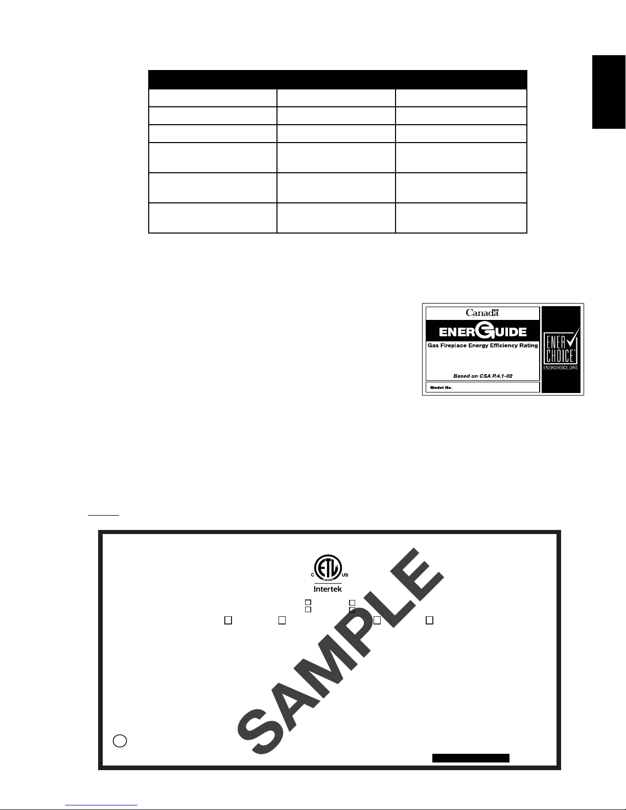
2.4 RATING PLATE INFORMATION
For rating plate location, see “INSTALLATION OVERVIEW” section.
This illustration is for reference only. Refer to the rating plate on the appliance for accurate information.
NOTE: The rating plate must remain with the appliance at all times. It must not be removed.
W415-1606 / 09.09.16
Page 8

8
WARNING
FOR BOTH VERTICAL AND HORIZONTAL RUNS. SPACERS ARE ATTACHED TO THE INNER PIPE AT
REQUIRED FOR SAFE OPERATION. A SPACER IS REQUIRED AT THE START, MIDDLE AND END OF
3.0 VENTING
EN
!
RISK OF FIRE, MAINTAIN SPECIFIED AIR SPACE CLEARANCES TO VENT PIPE AND APPLIANCE.
IF VENTING IS INCLUDED WITH SPACERS THE VENT SYSTEM MUST BE SUPPORTED EVERY 3FT
(0.9m) FOR BOTH VERTICAL AND HORIZONTAL RUNS. USE SUPPORTS OR EQUIVALENT
NON-COMBUSTIBLE STRAPPING TO MAINTAIN THE REQUIRED CLEARANCE FROM
COMBUSTIBLES. USE WOLF STEEL LTD. SUPPORT RING ASSEMBLY W010-0067 OR EQUIVALENT
NON-COMBUSTIBLE STRAPPING TO MAINTAIN THE MINIMUM CLEARANCE TO COMBUSTIBLES
PREDETERMINED INTERVALS TO MAINTAIN AN EVEN AIR GAP TO THE OUTER PIPE. THIS GAP IS
EACH ELBOW TO ENSURE THIS GAP IS MAINTAINED. THESE SPACERS MUST NOT BE REMOVED.
THIS APPLIANCE USES A 5” (127mm) EXHAUST / 8” (203.2mm) AIR INTAKE VENT PIPE SYSTEM.
Refer to the section applicable to your installation.
For safe and proper operation of the appliance follow the venting instruction exactly. Deviation from the
minimum vertical vent length can create diffi culty in burner start-up and/or carboning. Under extreme vent
confi gurations, allow several minutes (5-15) for the fl ame to stabilize after ignition. Provide a means for
visually checking the vent connection to the appliance after the appliance is installed. Use a fi restop, vent
pipe shield or attic insulation shield when penetrating interior walls, fl oor or ceiling.
NOTE: If for any reason the vent air intake system is disassembled; reinstall per the instructions
provided for the initial installation.
NOTE: This appliance must be installed with a continuous connection of exhaust and air intake vent
pipes. Utilizing alternate constructions such as a chimney as part of the vent system is not permitted.
7.2C
W415-1606 / 09.09.16
Page 9

3.1 VENTING LENGTHS AND COMPONENTS
For Simpson Dura-Vent, Selkirk Direct Temp, American Metal Amerivent and Metal-Fab follow the installation
vent pipe joints of all other approved vent systems except for the exhaust vent pipe connection to the appliance fl ue
For optimum fl ame appearance and appliance performance, keep the vent length and number of elbows to a
Rigid and fl exible venting systems must not be combined. Different venting manufacturer components must
maximum allowable horizontal run is 20 feet (6.1m). When terminating vertically, the maximum allowable vertical vent
9
Use only Wolf Steel, Simpson Dura-Vent, Selkirk Direct Temp, American Metal Amerivent or Metal-Fab
venting components. Minimum and maximum vent lengths, for both horizontal and vertical installations,
clearances from vent pipes to combustibles and air terminal locations as set out in this manual apply to
all vent systems and must be adhered to. For Simpson Dura-Vent, Selkirk Direct Temp, American Metal
Amerivent and Metal-Fab follow the installation procedure provided with the venting components.
A starter adaptor must be used with the following vent systems and may be purchased from the
corresponding supplier:
PART 5”/8” SUPPLIER WEBSITE
Duravent W175-0170 Wolf Steel www.duravent.com
Amerivent 5DSC-N2 American Metal www.americanmetalproducts.com
Direct Temp 5DT-AA Selkirk www.selkirkcorp.com
SuperSeal 5DDA Metal-Fab www.mtlfab.com
procedure found on the website for your venting supplier.
For vent systems that provide seals on the inner exhaust fl ue, only the outer air intake joints must be sealed using
a red high temperature silicone (RTV). This same sealant may be used on both the inner exhaust and outer intake
collar which must be sealed using the black high temperature sealant Mill Pac.
When using Wolf Steel venting components, use only approved Wolf Steel rigid / fl exible components with the
following termination kits: wall terminal kit GD422-1, GD422R-1, or 1/12 to 7/12 pitch roof terminal kit GD410, 8/12 to
12/12 roof terminal kit GD411, fl at roof terminal kit GD412 or periscope kit GD401 (for wall penetration below grade).
With fl exible venting, in conjunction with the various terminations, use either the 5 foot (1.5m) vent kit GD420 or the 10
foot (3.1m) vent kit GD430.
EN
minimum.
The air terminal must remain unobstructed at all times. Examine the air terminal at least once a year to verify
that it is unobstructed and undamaged.
not be combined.
These vent kits allow for either horizontal or vertical venting of the appliance. When terminating horizontally, the
length is 40 feet (12.2m). The maximum number of vent connections is two horizontally or three vertically (excluding
the appliance and the air terminal connections) when using fl exible venting.
Horizontal runs may have a 0” (0mm) rise per foot/meter however for optimum performance it is recommended that
all horizontal runs have a minimum 1/4” rise per foot or 21mm per meter using fl exible venting. For safe and proper
operation of the appliance, follow the venting instructions exactly.
A terminal shall not terminate directly above a sidewalk or paved driveway which is located between two single family dwellings and serves both dwellings. Local codes or regulations may require different clearances.
Do not allow the inside liner to bunch up on horizontal or vertical runs and elbows. Keep it pulled tight. A 1¼”
(31.8mm) air gap all around between the inner liner and outer liner is required for safe operation.
8.3C
W415-1606 / 09.09.16
Page 10
10
3.2 TYPICAL VENT INSTALLATION
EN
16" (40.6CM)
MINIMUM
40 FT (12M)
MAXIMUM
3 FT (1M)
MINIMUM
14" (35.5CM) MAXIMUM
Appliance shown without surround.
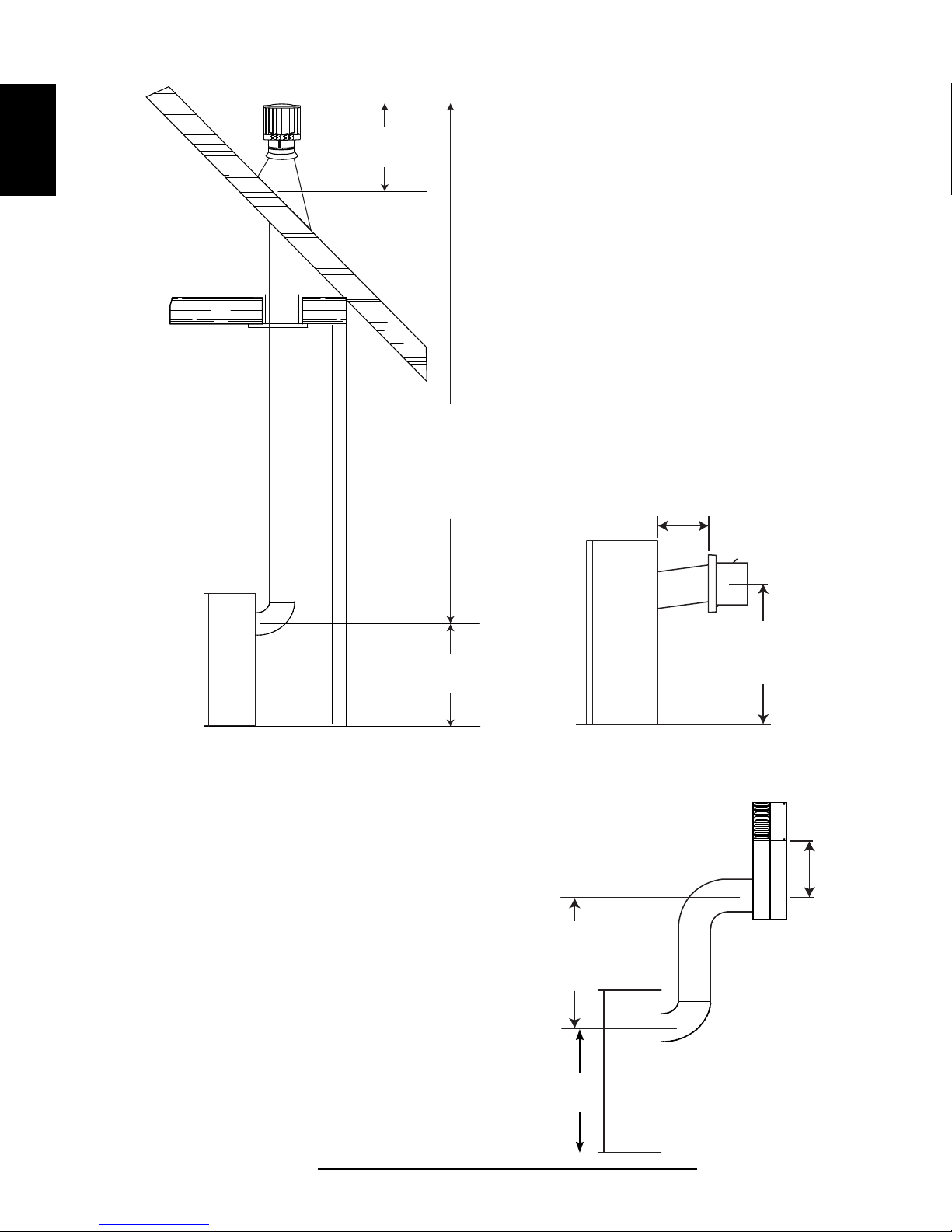
3.3 SPECIAL VENT INSTALLATIONS
3.3.1 PERISCOPE TERMINATION
Use the periscope kit to locate the air termination above grade. The periscope must be
installed so that when nal grading is completed, the bottom air slot is located a minimum
12” (304.8mm) above grade. The maximum allowable vent length is 10’ (3.1m) for a
replace and 8’ (2.4m) for a stove.
19 1/2"
(49.5CM)
19 1/2" (49.5CM)
MINIMUM PLUS
RISE*
* See "VENTING" section
12"
(30.5CM)
MINIMUM
TO GRADE
30" (76.2CM)
MINIMUM
19 1/2"
(49.5CM)
W415-1606 / 09.09.16
9.6B
Page 11
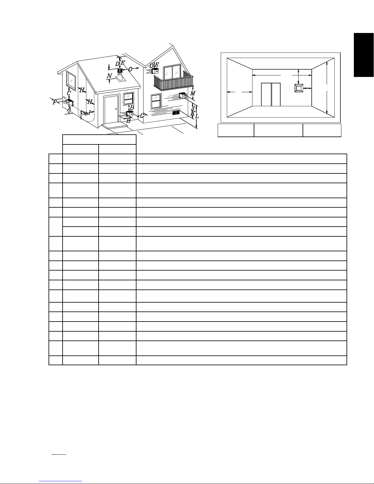
3.4 VENT TERMINAL CLEARANCES
COVERED BALCONY APPLICATIONS ††*
Q
S
R
G
P
11
EN
Q
= 3 feet
MIN
(0.9m)
R
= 2 x
MAX
Q
ACTUAL
R
MAX
INSTALLATIONS
CANADA U.S.A.
12” (30.5cm) 12” (30.5cm) Clearance above grade, veranda porch, deck or balcony.
A
Δ
12” (30.5cm)
B
12” (30.5cm)* 12” (30.5cm) * Clearance to permanently closed windows.
C
18”(45.7cm)** 18” (45.7cm)**
D
18” (45.7cm)** 18” (45.7cm)** Clearance to unventilated soffit.
E
0” (0mm) 0” (0mm) Clearance to an outside corner wall.
F
12” (30.5cm)*** 12” (30.5cm)***
G
12” (30.5cm)*** 12” (30.5cm)*** Clearance to an inside combustible corner wall or protruding combustible obstructions (vent chase, etc.).
H
K
M
3’(0.9m) 3’(0.9m)****
3’ (0.9m) 3’ (0.9m)**** Clearance to a service regulator vent outlet.
I
12” (30.5cm) 9” (22.9cm) Clearance to a non-mechanical air supply inlet to the building or a combustion air inlet to any other appliance.
J
6’ (1.8m) 3’ (0.9m) † Clearance to a mechanical air supply inlet.
7’ (2.1m) ‡ 7’ (2.1m) **** Clearance above a paved sidewalk or paved driveway located on public property.
L
12” (30.5cm)†† 12” (30.5cm)**** Clearance under a veranda, porch or deck.
9” (22.9cm) Clearance to windows or doors that open.
Vertical clearance to ventilated soffits located above the terminal within a horizontal distance of 2’
(0.6m) from the center line of the terminal.
Clearance to an inside non-combustible corner wall or protruding non-combustible obstructions (chimney, etc.).
Clearance to each side of the center line extended above the meter / regulator assembly to a maximum vertical distance of 15’ (4.6m).
≤ 15 feet
(4.6m)
16” (40.6cm) 16” (40.6cm) Clearance above the roof.
N
2’ (0.6m)†* 2’ (0.6m) †* Clearance from an adjacent wall including neighbouring buildings.
O
8’ (2.4m) 8’ (2.4m)
P
3’ (0.9m) 3’ (0.9m) See chart for wider wall dimensions.
Q
6’ (1.8m) 6’ (1.8m)
R
12” (30.5cm) 12” (30.5cm) Clearance under a covered balcony
S
Δ The terminal shall not be located less than 6 feet under a window that opens on a horizontal plane in a structure with three walls and a roof.
* Recommended to prevent condensation on windows and thermal breakage
** It is recommended to use a heat shield and to maximize the distance to vinyl clad soffits.
*** The periscope requires a minimum 18 inches clearance from an inside corner.
**** This is a recommended distance. For additional requirements check local codes.
† 3 feet above if within 10 feet horizontally.
‡ A vent shall not terminate where it may cause hazardous frost or ice accumulations on adjacent property surfaces.
†† Permitted only if the veranda, porch, or deck is fully open on a minimum of two sides beneath the floor.
†* Recommended to prevent recirculation of exhaust products. For additional requirements check local codes.
††* Permitted only if the balcony is fully open on a minimum of one side.
NOTE: Clearances are in accordance with local installation codes and the requirements of the gas supplier.
Roof must be non-combustible without openings.
See chart for deeper wall dimensions. The terminal shall not be installed on any wall that has an
opening between the terminal and the open side of the structure.
W415-1606 / 09.09.16
Page 12
12
For the following symbols used in the venting calculations and examples are:
> - greater than
>
< - less than
<
H
H
H
V
1° 0.03 0.5 12.7
15° 0.45 6.0 152.4
30° 0.9 11.0 279.4
45° 1.35 16.0 406.4
90°* 2.7 32.0 812.8
* The fi rst 90° offset has a zero value and is shown in the formula as - 90°
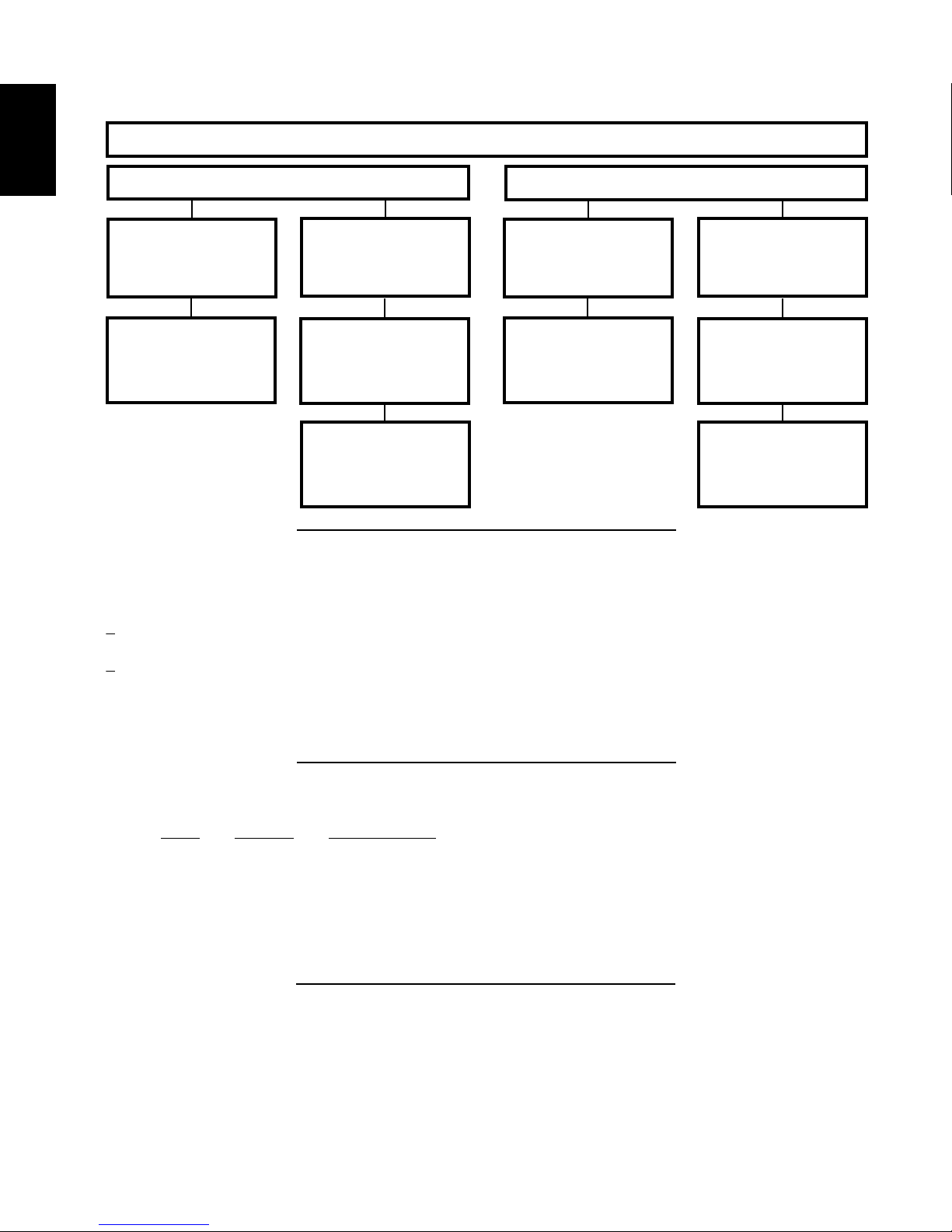
3.5 VENTING APPLICATION FLOW CHART
EN
Vertical rise is equal
to or greater than
the horizontal run
Horizontal run +
vertical rise to
maximum of 40 feet
3.6 DEFINITIONS
Horizontal Termination
Vertical rise is less
than horizontal run
Horizontal run +
vertical rise to
(12m)
24.75 feet (7.5m)
3.5 times the
vertical rise equal to
or greater than the
horizontal run
maximum of
REAR EXIT
Vertical rise is equal
the horizontal run
maximum of 40 feet
Vertical Termination
to or greater than
Horizontal run +
vertical rise to
(12m)
Vertical rise is less
than horizontal run
Horizontal run +
vertical rise to
maximum of 40 feet
(12m)
3 times the vertical
rise equal to or
greater than the
horizontal run
13.2A
- equal to or greater than
- equal to or less than
- total of both horizontal vent lengths (Hr) and offsets (Ho) in feet
T
- combined horizontal vent lengths in feet
R
- offset factor: .03 (total degrees of offset - 90°*) in feet
O
- combined vertical vent lengths in feet
T
3.7 ELBOW VENT LENGTH VALUES
FEET INCHES MILLIMETERS
W415-1606 / 09.09.16
14.1
15.1A
Page 13
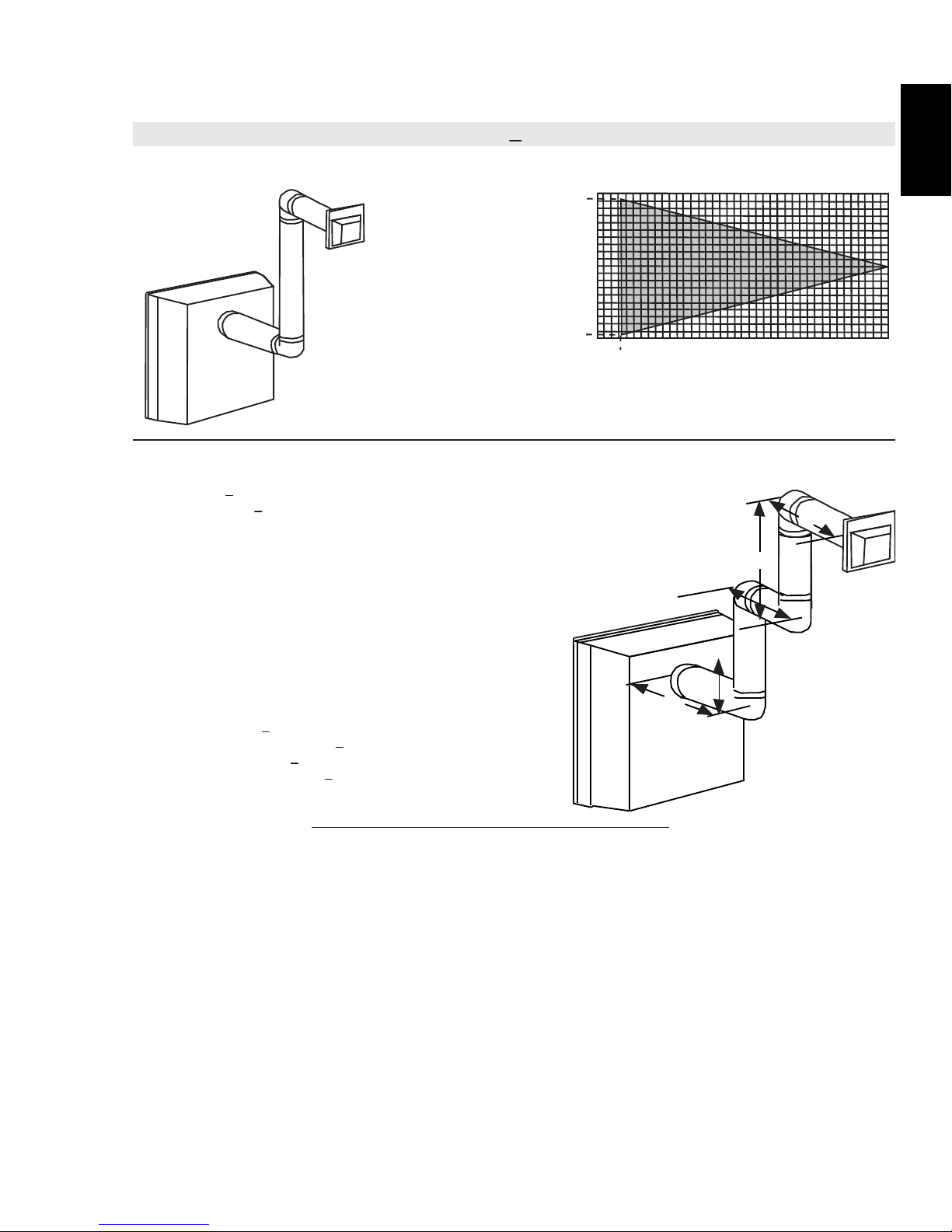
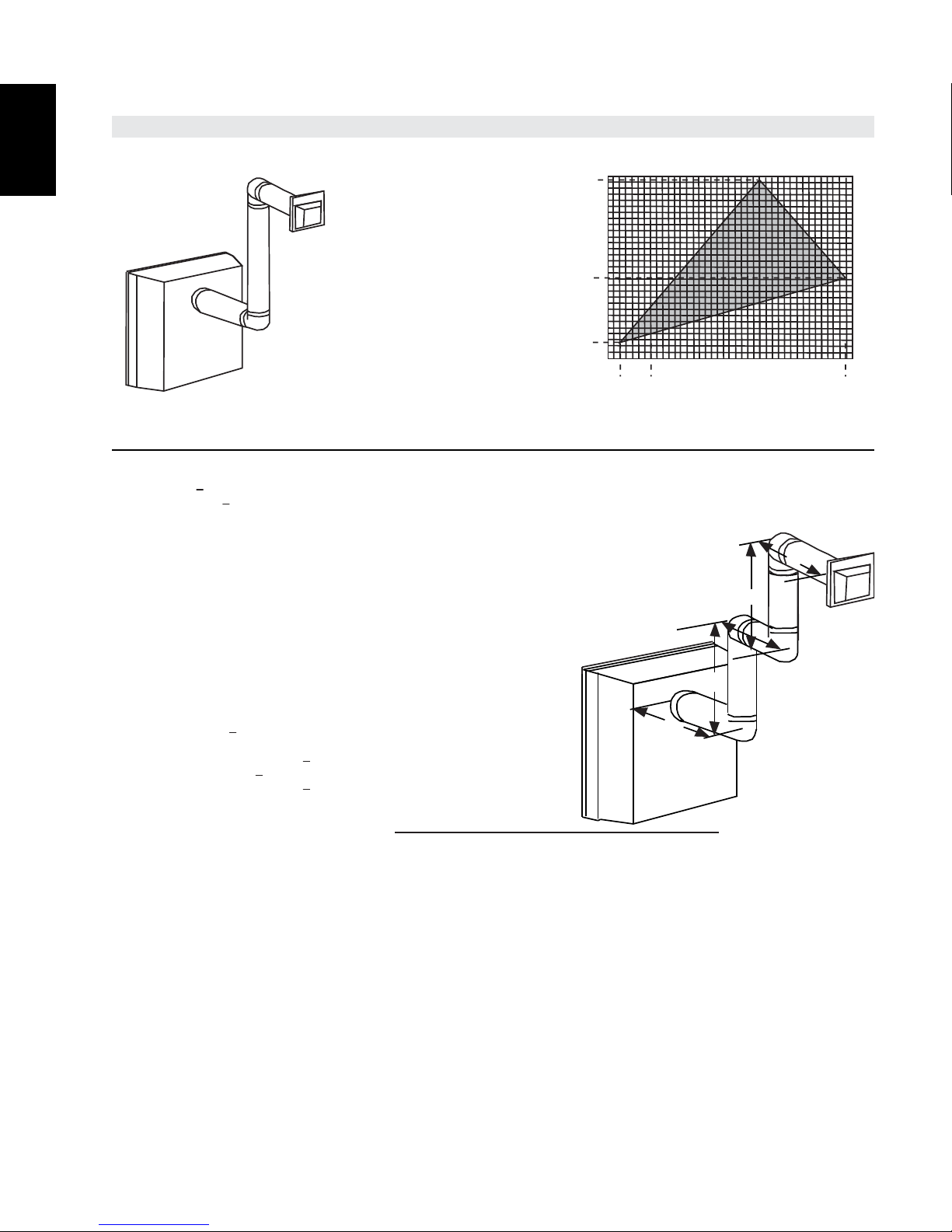
3.8 HORIZONTAL TERMINATION
(HT) < (VT)
13
Simple venting configuration
(only two 90° elbows)
See graph to determine the required vertical rise V
horizontal run H
40 (12.2)
38.3 (11.7)
REQUIRED
30 (9.1)
VERTICAL
RISE IN
20 (6.1)
FEET
(METERS) V
T
10 (3.1)
1.6 (0.5)
0
2.5
(0.8)5 (1.5)
1.6
(0.5)
HORIZONTAL VENT RUN PLUS OFFSET IN FEET (METERS) H
The shaded area within the lines represents acceptable values for H
and HT
For vent configurations requiring more than two 90° elbows, the following formulas apply:
Formula 1: H
Formula 2: HT + V
Example:
= 9 FT (2.7m)
V
1
V
= 6 FT (1.8m)
2
= V
V
T
1
= 3 FT (0.9m)
H
1
H
= 2 FT (0.6m)
2
= 1.5 FT (0.5m)
H
3
H
= H
R
= .03 (four 90° elbows - 90°) = .03 (360° - 90°) = 8.1 FT (2.5m)
H
O
= H
H
T
H
+ V
T
T
Formula 1: H
14.6 FT (4.5m) < 15 FT (4.6m)
Formula 2: HT + V
29.6 FT (9m) < 40 FT (12.2m)
< V
T
T
< 40 feet (12.2m)
T
+ V
= 9FT (2.7m) + 6FT (1.8m) = 15FT (4.6m)
2
+ H2 + H
1
+ H
R
= 14.6FT (4.5m) + 15FT (4.6m) = 29.6 FT (9m)
= 3FT (0.9m) + 2FT (0.6m) + 1.5FT (0.5m) = 6.5FT (2m)
3
= 6.5FT (2m) + 8.1FT (2.5m) = 14.6FT (4.5m)
O
< V
T
T
< 40 FT (12.2m)
T
H
1
Since both formulas are met, this vent configuration is acceptable.
(2.3)
EN
for the required
.
T
7.5
(3.1)
90°
V
1
T
10
12.5
15
17.5
(3.8)
(4.6)
(5.3)
(6.1)
T
20
T
90°
H
3
V
2
H
2
90°
90°
16.3A
W415-1606 / 09.09.16
Page 14
14
(HT) > (VT)
EN
Simple venting configuration
(only two 90° elbows)
See graph to determine the required vertical rise V
12.5 (3.8)
12.25 (3.7)
REQUIRED
VERTICAL RISE IN
8.3 (2.54)
FEET
(METERS)V
T
(1.68)
(0.3)
5.5
4.2 (1.3)
1
0
HORIZONTAL VENT RUN PLUS OFFSET IN FEET (METERS) H
The shaded area within the lines represents acceptable
For vent configurations requiring more than two 90° elbows, the following formulas apply:
Formula 1: H
Formula 2: HT + V
Example:
= 4 FT (1.2m)
V
1
V
= 1.5 FT (0.5m)
2
= V
V
T
= 2 FT (0.6m)
H
1
H
= 1 FT (0.3m)
2
= 1 FT (0.3m)
H
3
H
= 1.5 FT (0.5m)
4
= H1+ H2+H3+H4= 2FT(0.6m) + 1FT(0.3m) + 1FT(0.3m) + 1.5FT(0.5m) = 5.5 FT(1.7m)
H
R
= .03 (four 90° elbows + one 45° elbow - 90°)
H
O
= .03 (90 + 90 + 90 + 90 + 45 - 90) = 9.45 FT (2.9m)
H
= H
T
H
+ V
T
Formula 1: H
3.5VT = 3.5FT (1.1m) x 5.5FT (1.7m) = 19.25FT (5.9m)
14.95 FT (4.6m) < 19.25 FT (5.9m)
Formula 2: HT + V
20.45 FT (6.2m) < 24.75 FT (7.5m)
< 3.5V
T
T
< 24.75 feet (7.5m)
T
+ V
= 4FT (1.2m) + 1.5FT (0.5m) = 5.5 FT (1.7m)
1
2
+ H
= 5.5FT (1.7m) + 9.45FT (2.9m) = 14.95FT (4.6m)
R
O
= 14.95FT (4.6m) + 5.5FT (1.7m) = 20.45FT (6.2m)
T
< 3.5V
T
T
< 24.75 FT (7.5m)
T
Since both formulas are met, this vent configuration is acceptable.
required horizontal run H
2.5
(0.8)5 (1.5)
1
(0.3)
values for H
(1.1)
3.5
7.5
(2.3)
and HT
T
V
1
H
1
(3.1)
90°
for the
T
.
T
10
12.5
15
17.5
(3.8)
(4.6)
(5.3)
19.25
(5.9)
(6.1)
20
T
90°
H
3
V
2
H
2
90°
90°
W415-1606 / 09.09.16
16.3_2C
Page 15

for the
T
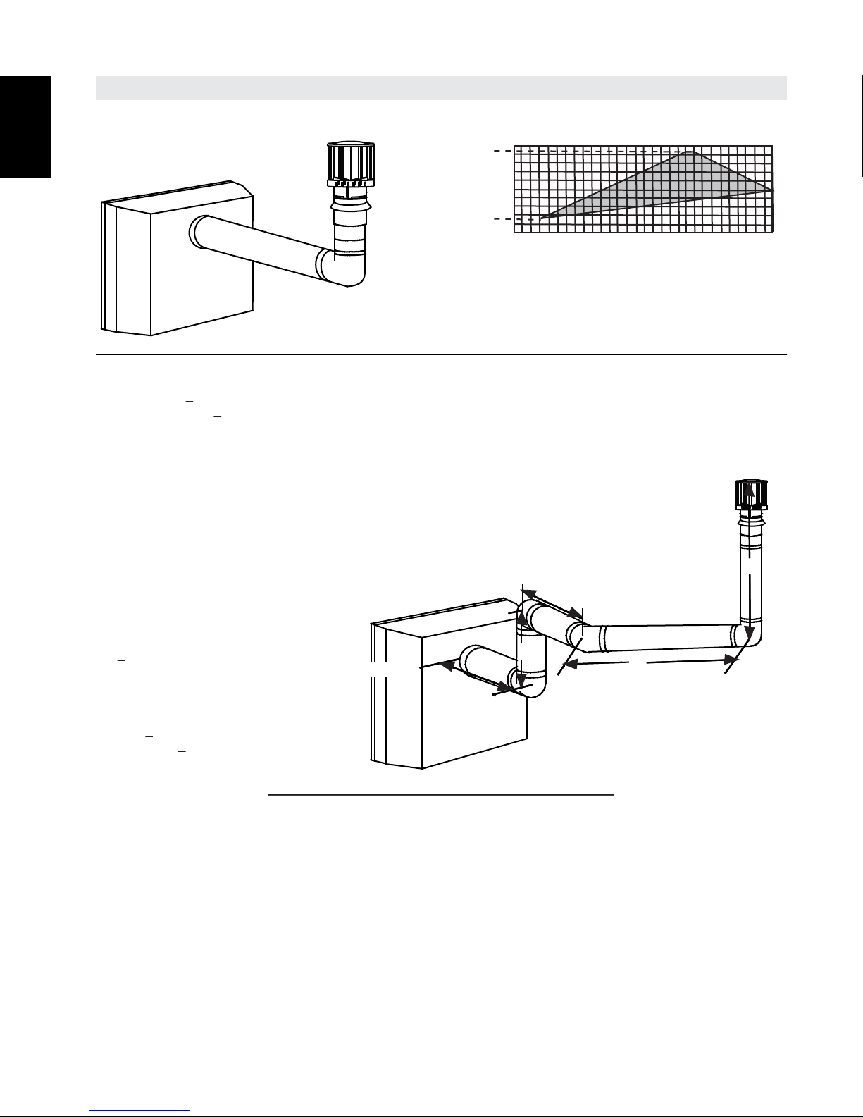
(HT) < (VT)
90°
3.9 VERTICAL TERMINATION
15
Simple venting configurations.
See graph to determine the required vertical rise V
required horizontal run H
40 (12.2)
30 (9.1)
REQUIRED
VERTICAL
20 (6.1)
RISE IN FEET
(METERS)V
T
3 (0.9)
10 (3.1)
0
5
(1.5)
(3.1)
HORIZONTAL VENT RUN PLUS OFFSET IN FEET (METERS) H
The shaded area within the lines represents acceptable
values for H
and VT
T
For vent configurations requiring more than one 90° elbow, the following formulas apply:
Formula 1: H
Formula 2: HT + V
< V
T
T
< 40 feet (12.2m)
T
10
15
(4.6)
EN
.
T
V
T
20
(6.1)
2
Example:
= 5 FT (1.5m)
V
1
= 10 FT (3.1m)
V
2
V
= V
+ V
T
= 3 FT (0.9m)
H
1
H
= 2.5 FT (0.8m)
2
= H
H
R
H
= .03 (three 90° elbows - 90°)
O
= .03 (270° - 90°) = 5.4 FT (1.6m)
= H
H
T
H
+ V
T
Formula 1: H
10.9 FT (3.3m) < 15 FT (4.6m)
Formula 2: HT + V
25.9 FT (7.9m) < 40 (12.2m)
= 5FT (1.5m) + 10FT (3.1m) = 15 FT (4.6m)
1
2
+ H
= 3FT (0.9m) + 2.5FT (0.8m) = 5.5 FT (1.7m)
1
2
+ H
= 5.5FT (1.7m) + 5.4FT (1.6m) = 10.9 FT (3.3m)
R
O
= 10.9 FT (3.3m) + 15 FT (4.6m) = 25.9 FT (7.9m)
T
< V
T
T
< 40 FT (12.2m)
T
Since both formulas are met, this vent configuration is acceptable.
H
1
18.6A
90°
V
H
2
1
90°
W415-1606 / 09.09.16
Page 16
for the
(HT) > (VT)
EN
16
Simple venting configurations.
See graph to determine the required vertical rise V
required horizontal run HT.
20 (6.1)
19 (5.8)
REQUIRED
VERTICAL
RISE IN
FEET
(METERS)V
T
3 (0.9)
10 (3.1)
5
0
(1.5)
10
(3.1)
HORIZONTAL VENT RUN PLUS OFFSET IN
FEET (METERS) H
The shaded area within the lines represents acceptable
values for H
For vent configurations requiring more than one 90° elbow, the following formulas apply:
15
(4.6)
and vT
T
(6.1)
T
20
25
(7.6)
T
30
(9.1)
Formula 1: H
Formula 2: HT + V
< 3 V
T
T
< 40 FT (12.2m)
T
Example:
= 1.5 FT (0.5m)
V
1
V
= 5 FT (1.5m)
2
= V
V
H
H
H
H
H
= .03 (270° + 45° - 90°) = 6.75 FT (2.1m)
H
H
+ V2 = 1.5FT (0.5m) + 5FT (1.5m) = 6.5 FT (2m)
T
1
= 1 FT (0.3m)
1
= 1 FT (0.3m)
2
= 10.75 FT (3.3m)
3
= H
+ H2 + H3 = 1FT (0.3m) + 1FT (0.3m) + 10.75FT (3.3m) = 12.75 FT (3.9m)
R
1
= .03 (three 90° elbows + one 45° elbow - 90°)
O
= H
+ H
T
T
+ V
= 12.75FT (3.9m) + 6.75FT (2.1m) = 19.5 FT (5.9m)
R
O
= 19.5FT (5.9m) + 6.5FT (2m) = 26 FT (7.9m)
T
Formula 1:
< 3 V
H
T
3 V
19.5FT (5.9m) = 19.5FT (5.9m)
T
= 3FT (0.9m) x 6.5FT (2m) = 19.5FT (5.9m)
T
Formula 2:
H
+ V
< 40 FT (12.2m)
T
T
26 FT (7.9m) < 40 FT (12.2m)
Since both formulas are met, this vent configuration is acceptable.
V
2
90°
H
2
45°
V
1
H
1
H
3
90°
90°
18.7A
W415-1606 / 09.09.16
Page 17

4.0 INSTALLATION
WARNING
ENSURE TO UNPACK ALL LOOSE MATERIALS FROM INSIDE THE FIREBOX PRIOR TO HOOKING UP
IF USING PIPE CLAMPS TO CONNECT VENT COMPONENTS, A MINIMUM OF 3 SCREWS MUST ALSO
WARNING
17
!
THE GAS AND ELECTRICAL SUPPLY.
IF YOUR APPLIANCE IS SUPPLIED WITH A REMOTE ENSURE THE REMOTE RECEIVER IS IN THE
“OFF” POSITION PRIOR TO HOOKING UP THE GAS AND ELECTRICAL SUPPLY TO THE APPLIANCE.
FOR SAFE AND PROPER OPERATION OF THE APPLIANCE, FOLLOW THE VENTING INSTRUCTIONS
EXACTLY.
ALL EXHAUST AND INTAKE VENT PIPE JOINTS MUST BE SEALED USING RED RTV HIGH TEMP
SILICONE SEALANT W573-0002 (NOT SUPPLIED) OR BLACK HIGH TEMP MILL PAC W573-0007 (NOT
SUPPLIED) WITH THE EXCEPTION OF THE APPLIANCE EXHAUST FLUE COLLAR WHICH MUST BE
SEALED USING MILL PAC.
BE USED TO ENSURE THE CONNECTION CANNOT SLIP OFF.
DO NOT CLAMP THE FLEXIBLE VENT PIPE.
RISK OF FIRE, EXPLOSION OR ASPHYXIATION. IMPROPER SUPPORT OF THE ENTIRE VENTING
SYSTEM MAY ALLOW VENT TO SAG AND SEPARATE. USE VENT RUN SUPPORTS AND CONNECT
VENT SECTIONS PER INSTALLATION INSTRUCTIONS.
RISK OF FIRE, DO NOT ALLOW LOOSE MATERIALS OR INSULATION TO TOUCH THE VENT PIPE.
REMOVE INSULATION TO ALLOW FOR THE INSTALLATION OF THE ATTIC SHIELD AND TO
MAINTAIN CLEARANCES TO COMBUSTIBLES.
68.2D
EN
4.1 WALL AND CEILING PROTECTION
!
DO NOT FILL THE SPACE BETWEEN THE VENT PIPE AND ENCLOSURE WITH ANY TYPE OF
MATERIAL. DO NOT PACK INSULATION OR COMBUSTIBLES BETWEEN CEILING FIRESTOPS.
ALWAYS MAINTAIN SPECIFIED CLEARANCES AROUND VENTING AND FIRESTOP SYSTEMS.
INSTALL WALL SHIELDS AND FIRESTOPS AS SPECIFIED. FAILURE TO KEEP INSULATION OR
OTHER MATERIALS AWAY FROM VENT PIPE MAY CAUSE FIRE.
70.1
W415-1606 / 09.09.16
Page 18

18
CAULKING
WALL
REAR VIEW
4.2 MOUNTING PLATE INSTALLATION
EN
A. Level and afx the mounting template to the wall at the desired location and height. The centre of the
vent pipe must be centered between wall studs.
B. Using the template, mark the holes for the vent, gas and electrical outlets, and mounting screw
locations. See “MINIMUM CLEARANCES TO COMBUSTIBLES” section. NOTE : Choose the
appropriate screws required for either combustible or non-combustible material. A minimum of
four screws must be used to mount appliance into wall studs.
C. Remove the mounting template from the wall and cut/drill the required holes as marked.
D. Screw the vent shield together using the screws provided (Fig. 1).
E. Bend the 4 tabs on the restop spacer outwards. Slide the vent shield into the restop spacer aligning
the holes within the tabs. Using 4 of the screws provided, secure the vent shield to the restop spacer
(Fig. 2).
F. The vent shield and restop spacer have been designed to accommodate a maximum wall depth of
14" (35.6cm). The vent shield must extend the full depth of the combustible wall. Trim the vent shield
to suit as necessary.
G. Apply a bead of caulking (not supplied) to the ange perimeter and wings of the restop spacer. Insert
the restop spacer with mounted vent shield into the wall and level the restop spacer. Once leveled,
secure restop spacer to the wall using 4 fasteners (Fig. 3).
H. Install mounting plate by aligning dimples on restop spacer and secure using four screws provided.
(Fig. 4)
W415-1606 / 09.09.16
FIG.1 FIG.2
FIG.3 FIG.4
Page 19

19
temperature sealant W573-0007 Mill Pac (not supplied). However, the high
SPACERS ARE ATTACHED TO THE INNER FLEX PIPE AT PREDETERMINED INTERVALS TO MAINTAIN AN EVEN
WARNING
A. Install the inner ex pipe to the replace. Secure with a
B.
TEMPERATURE
FIG.5
4.3 USING FLEXIBLE VENT COMPONENTS
!
DO NOT ALLOW THE INNER FLEX PIPE TO BUNCH UP ON HORIZONTAL OR VERTICAL RUNS AND ELBOWS.
KEEP IT PULLED TIGHT.
AIR GAP TO THE OUTER FLEX PIPE. THIS GAP IS REQUIRED FOR SAFE OPERATION. A SPACER IS REQUIRED
AT THE START, MIDDLE AND END OF EACH ELBOW TO ENSURE THIS GAP IS MAINTAINED. THESE SPACERS
MUST NOT BE REMOVED.
I. Look through slotted holes on the mounting
plate for pre-marked stud locations and
secure mounting plate using a minimum of 4
screws (minimum 1 screw per corner must be
mounted to a wall stud) (Fig. 5).
J. See the following sections up to the
“FINISHING” section for venting and
mounting instructions.
EN
For safe and proper operation of the appliance, follow the venting
instructions exactly.
All inner fl ex pipe and outer fl ex pipe joints may be sealed using high
ELBOW
SPACERS
temperature red RTV silicone W573-0002 (not supplied) or the high
temperature sealant W573-0007 Mill Pac (not supplied) must be used on
the joint connecting the inner fl ex pipe and the exhaust fl ue collar.
Use only approved fl exible vent pipe kits marked:
“Wolf Steel Approved Venting” as identifi ed by
the stamp only on the outer fl ex pipe.
4.3.1 APPLIANCE VENT CONNECTION
minimum 3 screws and at washers. Seal the joint and
screw holes using Mill Pac sealant (W573-0007) (not
supplied).
Install the outer ex pipe to the replace. Secure with a
minimum of 3 screws and at washers. Seal the joints
using red RTV silicone (W573-0002) (not supplied).
1
/2” OVERLAP
1
(38.1mm)
SCREWS
22.1A
HIGH
SEALANT
28.4B
W415-1606 / 09.09.16
Page 20

20
VENT
A. Stretch the inner fl ex pipe to the required length taking into
B.
C.
D.
The air terminal mounting plate may be recessed into the exterior wall or siding no greater than the depth
of its return fl ange.
#8 X 1/2” SELF DRILLING
FLEX PIPE
HI-TEMP
SEALANT
4.3.2 VERTICAL INSTALLATION
EN
This application occurs when venting through a roof. Installation kits for
various roof pitches are available from your authorized dealer / distributor.
See accessories to order specifi c kits required.
A. Determine the air terminal location, cut and frame a square opening as
illustrated in the ceiling and the roof to provide the minimum 1" (25mm)
clearance between the vent pipe and any combustible material. Try to
center the vent pipe location midway between two joists to prevent
having to cut them. Use a plumb bob to line up the center of the
openings. A vent pipe shield will prevent any materials such as
insulation, from fi lling up the 1" (25mm) air space around the pipe.
Nail headers between the joist for extra support.
B. Apply a bead of caulking (not supplied) to the framework or to the
Wolf Steel vent pipe shield plate or equivalent (in the case of a fi nished
ceiling), and secure over the opening in the ceiling. A fi restop must be placed
on the bottom of each framed opening in a roof or ceiling that the venting
VENT PIPE
SHIELD
system passes through. Apply a bead of caulking all around and place a
fi restop spacer over the vent shield to restrict cold air from being drawn into the
room or around the fi replace. Ensure that both spacer and shield maintain the required
clearance to combustibles. Once the vent pipe is installed in its fi nal position, apply
Mill Pac sealant (W573-0007) (not supplied) or red RTV silicone (W573-0002) (not
supplied) between the pipe and the fi restop assembly.
C. In the attic, slide the vent pipe collar down to cover up the open end of the shield and
tighten. This will prevent any materials, such as insulation, from fi lling up the 1" (25mm)
air space around the pipe.
8”
8”
FIRESTOP
UNDERSIDE OF
JOIST
CAULKING
PIPE
COLLAR
VENT
PIPE
SHIELD
21.1B
4.3.3 HORIZONTAL AIR TERMINAL INSTALLATION
account the additional length needed for the fi nished wall
surface. Apply a heavy bead of the Mill Pac sealant
(W573-0007) (not supplied) to the inner sleeve of
the air terminal. Slip the vent pipe a minimum of 2”
(50.8mm) over the inner sleeve of the air terminal and
secure with a minimum of 3 #8 screws.
Using the outer fl ex pipe, slide over the outer
combustion air sleeve of the air terminal and secure with
a minimum of 3 #8 screws. Seal using red RTV silicone
(W573-0002) (not supplied).
Insert the vent pipes through the fi restop maintaining the
required clearance to combustibles. Holding the air terminal
(lettering in an upright, readable position), secure to the
exterior wall and make weather tight by sealing with
caulking (not supplied).
If more vent pipe needs to be used to reach the fi replace,
couple them together as illustrated. The vent system must
be supported approximately every 3 feet (0.9m) for both
vertical and horizontal runs. Use noncombustible strapping
to maintain the minimum clearance to combustibles.
#10x2"
SCREWS
HI-TEMP
SEALANT
OUTER
FLEX PIPE
CAULKING
INNER FLEX
PIPE
2" (50.8mm) OVERLAP
HIGH TEMPERATURE
INNER
FLEX PIPE
OUTER FLEX PIPE
SEALANT
SCREWS
INNER COUPLER
OUTER COUPLER
OUTER
W415-1606 / 09.09.16
23.1C
Page 21

4.3.4 VERTICAL AIR TERMINAL INSTALLATION (FLEXIBLE)
A.
B.
C.
D.
E.
F.
G.
H.
WARNING
21
!
MAINTAIN A MINIMUM 2” (51mm) SPACE BETWEEN THE AIR INLET BASE AND THE STORM COLLAR.
Fasten the roof support to the roof using the screws provided. The
roof support is optional. In this case the venting is to be adequately
supported using either an alternate method suitable to the
authority having jurisdiction or the optional roof support.
Stretch the inner fl ex pipe to the required length. Slip the
inner fl ex pipe a minimum of 2” (51mm) over the inner pipe
of the air terminal connector and secure with a minimum of
3 #8 screws. Seal using a heavy bead of Mill Pac sealant
(W573-0007) (not supplied).
Repeat using the outer fl ex pipe, using a heavy bead
of red RTV silicone (W573-0002) (not supplied) and a
minimum of 3 #8 screws.
Thread the air terminal connector / vent pipe assembly down through
the roof. The air terminal must be positioned vertically and plumb.
Attach the air terminal connector to the roof support, ensuring that
the top of the air terminal is 16” (406mm) above the highest point
that it penetrates the roof.
Remove nails from the shingles, above and to the sides of the air
terminal connector. Place the fl ashing over the air terminal connector
leaving a min. 3/4” (19mm) of the air terminal connector showing
above the top of the fl ashing. Slide the fl ashing underneath the
sides and upper edge of the shingles. Ensure that the air terminal
connector is properly centered within the fl ashing, giving a 3/4”
(19mm) margin all around. Fasten to the roof. Do not nail through
the lower portion of the fl ashing. Make weather-tight by sealing with
caulking. Where possible, cover the sides and top edges of the
fl ashing with roofi ng material.
Aligning the seams of the terminal and air terminal connector,
place the terminal over the air terminal connector making sure
the vent pipe goes into the hole in the terminal. Secure with
the three screws provided.
Apply a heavy bead of weatherproof caulking 2” (51mm)
above the fl ashing. Install the storm collar around the air
terminal and slide down to the caulking. Tighten to ensure that
a weather-tight seal between the air terminal and the collar is
achieved.
If more vent pipe needs to be used to reach the appliance see
“HORIZONTAL AIR TERMINAL INSTALLATION” section.
ROOF SUPPORT
AIR
TERMINAL
CONNECTOR
2” (51mm)
INNER PIPE
MILL PAC
SEALANT
(W572-0007)
INNER FLEX PIPE
OUTER FLEX PIPE
AIR INLET
BASE
CAULKING
STORM COLLAR
WEATHER
SEALANT
FLASHING
24.1C
EN
W415-1606 / 09.09.16
Page 22

22
A. Move the appliance into position. Measure the vent
B.
C.
The air terminal mounting plate may be recessed into the exterior wall or siding no greater than the
depth of the return fl ange.
REMOVE INSULATION TO ALLOW FOR THE INSTALLATION OF THE ATTIC SHIELD AND TO MAINTAIN
A 45° corner installation can have 0” (0mm) rise between the appliance
4.3.5 HORIZONTAL AIR TERMINAL INSTALLATION
EN
!
WARNING
RISK OF FIRE, DO NOT ALLOW LOOSE MATERIALS OR INSULATION TO TOUCH THE VENT PIPE.
CLEARANCES TO COMBUSTIBLES.
length required between terminal and appliance
taking into account the additional length
needed for the nished wall surface and any
1¼” (31.8mm) overlaps between venting
components.
Apply high temperature sealant W573-0007
(not supplied) to the outer edge of the inner collar
of the appliance. Attach the rst inner rigid pipe
component and secure using 3 self tapping screws.
Repeat using the outer rigid pipe.
Holding the air terminal (lettering in an upright, readable
position), secure to the exterior wall and make weather tight by sealing with caulking (not supplied).
#10x2"
SCREWS
CAULKING
OUTER
RIGID
PIPE
26.4A
1" (25.4mm)
OVERLAP
HI-TEMP
INNER
RIGID
PIPE
#8x1/2"
SELF DRILLING
SCREWS
SEALANT
4.3.6 EXTENDED HORIZONTAL AND CORNER TERMINAL INSTALLATION
combustion air collar and the air terminal. In this case, vent lengths must be
kept to a maximum of 24” (609.6mm) . For longer vent lengths, a minimum
vertical rise of 24” (609.6mm) is required.
A. Follow the instructions for "HORIZONTAL AIR TERMINAL
INSTALLATION" section.
B. Continue adding components alternating inner and outer vent pipes. Ensure that
all inner vent pipes and elbows have sufficient vent spacers attached and each
component is securely fastened to the one prior. Attach the telescopic sleeve to the
vent run. Secure and seal. To facilitate completion, attach inner and outer couplers to
the air terminal.
C. Install the air terminal. See “HORIZONTAL AIR TERMINAL INSTALLATION” section. Extend the outer
telescopic sleeve; connect to the air terminal assembly. Fasten with self tapping screws and seal.
AIR TERMINAL
20" (508mm)
COUPLER
48.2A
TELESCOPIC SLEEVE
VENTING
W415-1606 / 09.09.16
Page 23

4.4 MOUNTING THE WHD48
23
A. Guide the vent pipe through
the shield on the mounting
plate and secure the
appliance to the mounting
plate as illustrated using 8
screws.
EN
VENT SHIELD
MOUNTING PLATE
W415-1606 / 09.09.16
Page 24

24
Installation and servicing to be done by a qualifi ed installer.
•
•
•
current CAN/CSA-B149.1 Installation Code in Canada or to the current National Fuel Gas Code, ANSI
•
• The gas line fl ex-connector should be installed to provide suffi cient movement for shifting the burner
•
WARNING
RISK OF FIRE, EXPLOSION OR ASPHYXIATION. ENSURE THERE ARE NO IGNITION SOURCES SUCH AS
PERFORMED BY A QUALIFIED SERVICE TECHNICIAN. ASSURE THAT A CONTINUOUS GAS FLOW IS AT
Conversion Kits
This appliance is eld convertible between Natural Gas (NG) and Propane (P).
To convert from one gas to another consult your Authorized dealer/distributor.
4.5 GAS INSTALLATION
EN
!
SPARKS OR OPEN FLAMES.
SUPPORT GAS CONTROL WHEN ATTACHING GAS SUPPLY PIPE TO PREVENT DAMAGING GAS LINE.
ALWAYS LIGHT THE PILOT WHETHER FOR THE FIRST TIME OR IF THE GAS SUPPLY HAS RUN OUT
WITH THE GLASS DOOR OPENED OR REMOVED. PURGING OF THE GAS SUPPLY LINE SHOULD BE
THE BURNER BEFORE CLOSING THE DOOR. ENSURE ADEQUATE VENTILATION. FOR GAS AND
ELECTRICAL LOCATIONS, SEE “DIMENSIONS” SECTION.
ALL GAS CONNECTIONS MUST BE CONTAINED WITHIN THE APPLIANCE WHEN COMPLETE.
HIGH PRESSURE WILL DAMAGE VALVE. DISCONNECT GAS SUPPLY PIPING BEFORE TESTING GAS
LINE AT TEST PRESSURES ABOVE 1/2 PSIG.
VALVE SETTINGS HAVE BEEN FACTORY SET, DO NOT CHANGE.
Move the appliance into position and secure.
If equipped with a fl ex connector the appliance is designed to accept a 1/2” (13mm) gas supply.
Without the connector it is designed to accept a 3/8” (9.5mm) gas supply. The appliance is equipped
with a manual shut off valve to turn off the gas supply to the appliance.
Connect the gas supply in accordance to local codes. In the absence of local codes, install to the
Z223.1 / NFPA 54 in the United States.
When fl exing any gas line, support the gas valve so that the lines are not bent or kinked.
assembly on its side to aid with servicing components.
Check for gas leaks by brushing on a soap and water solution. Do not use open fl ame.
30.1A
4.6 MOBILE HOME
This Mobile/Manufactured Home Listed appliance comes factory equipped with a means to secure the unit. Built
in appliances are equipped with 1/4” diameter holes located in the front left and right corners of the base. Use #10
hex head screws, inserted through the holes in the base to secure. For free standing products contact your local
authorized dealer / distributor for the appropriate securing kit. For mobile home installations, the appliance must be
fastened in place. It is recommended that the appliance be secured in all installations. Always turn off the pilot and
the fuel supply at the source, prior to moving the mobile home. After moving the mobile home and prior to lighting
the appliance, ensure that the logs are positioned correctly.
This appliance is certi ed to be installed in an aftermarket permanently located, manufactured (mobile)
home, where not prohibited by local codes.
This appliance is only for use with the type of gas indicated on the rating plate. This appliance is not
convertible for use with other gases, unless a certi ed kit is used.
29.6A
W415-1606 / 09.09.16
Page 25

15" (38.1 cm)
MIN.
36"
(91.4 cm)
MAX.
7"
(17.8 cm)
MIN.
7"
(17.8 cm)
MIN.
36"
(91.4cm)
MAX.
4.5" (11.4 cm) MIN.
15" (38.1 cm)
MIN.
6" (15.2 cm) MIN.
4.5" (11.4 cm) MIN.
6" (15.2 cm) MIN.
4.7 MINIMUM CLEARANCE TO COMBUSTIBLES AND NON-COMBUSTIBLES
25
MINIMUM CLEARANCE TO COMBUSTIBLE CONSTRUCTION FROM APPLIANCE AND VENT
SURFACES:
- 1/2" (13mm) to wall mounting plate
- 1" (2.5cm) to bottom and sides of vent pipe*
- 3" (7.6cm) to top of vent pipe*
MINIMUM CLEARANCES TO COMBUSTIBLES (FROM THE APPLIANCE):
- 15" (38.1cm) to top/ceiling
- 7" (17.8cm) to sides
- 6” (15.2cm) to bottom
- 1/2" (13mm) to rear
* A minimum of 1" (25mm) all around the vent pipe on all vertical runs to combustibles is required.
EN
ALCOVE
INSTALLATION
TOP VIEW
ALCOVE
INSTALLATION
SIDE VIEW
TYPICAL
INSTALLATION
W415-1606 / 09.09.16
Page 26

26
WARNING
5.0 FINISHING
EN
NEVER OBSTRUCT THE FRONT OPENING OF THE APPLIANCE.
DO NOT STRIKE, SLAM OR SCRATCH GLASS. DO NOT OPERATE APPLIANCE WITH GLASS
REMOVED, CRACKED, BROKEN OR SCRATCHED.
5.1 HOUSING PANEL INSTALLATION
A. Secure the housing panels as illustrated using the 16 #8 x 1/2” pan head screws and 10 #9 x 1/2” 1/4”
hex head screws supplied.
- 5 #9 hex head screws secure the top housing panel. (Step 1)
- 5 #9 hex head screws secure the bottom housing panel. (Step 2)
- 8 #8 pan head screws secure each of the side housing panels. (Steps 3 & 4)
!
RISK OF FIRE!
1
3
2
4
NOTE : DO NOT PINCH WIRES.
W415-1606 / 09.09.16
Page 27

IF EQUIPPED WITH DOOR LATCHES THAT ARE PART OF A SAFETY RELIEF SYSTEM, THEY MUST BE
BEFORE DOOR IS REMOVED TURN THE APPLIANCE OFF AND WAIT UNTIL APPLIANCE IS COOL TO
5.2 DOOR REMOVAL / INSTALLATION
The distribution of glass media over the burner ports will infl uence the fl ame height. When the
Glass media may have a ne oil residue that needs to be cleaned prior to installation. Clean the glass with mild
WARNING
27
!
WARNING
GLASS MAY BE HOT, DO NOT TOUCH GLASS UNTIL COOLED.
PROPERLY ENGAGED. DO NOT OPERATE THE APPLIANCE WITH LATCHES DISENGAGED.
FACING AND/OR FINISHING MATERIALS MUST NOT INTERFERE WITH AIR FLOW THROUGH AIR
OPENINGS, LOUVRE OPENINGS, OPERATION OF LOUVRES OR DOORS OR ACCESS FOR
SERVICE. OBSERVE ALL CLEARANCES WHEN APPLYING COMBUSTIBLE MATERIALS.
THE TOUCH. DOORS ARE HEAVY AND FRAGILE SO HANDLE WITH CARE.
75.1A
A. Remove the surround with safety screen.
(see “SURROUND INSTALLATION /
REMOVAL” section).
B. Remove the 5 screws that secure the
door.
C. Lift the door up and off.
D. Reverse steps to reinstall the door and
safety screen with surround.
NOTE: A barrier designed to reduce the risk of
burns from the hot viewing glass is provided
with the appliance and must be installed.
EN
5.3 GLASS MEDIA
!
CLEAN THE GLASS MEDIA PRIOR TO INSTALLATION. BEFORE APPLYING THE CLEANED GLASS, ENSURE
THAT IT IS DRY.
DO NOT CHANGE OR SUBSTITUTE THE GLASS MEDIA MATERIAL PROVIDED WITH THIS APPLIANCE. IF
REPLACING, USE ONLY THE REPLACEMENT GLASS MEDIA AVAILABLE FROM YOUR AUTHORIZED
DEALER / DISTRIBUTOR.
GLASS MEDIA OVER THE BURNER MUST NOT BE MORE THAN ONE LAYER HIGH. MORE THAN ONE LAYER
OVER THE BURNER WILL CAUSE FLAME LIFTING AND SOOTING PROBLEMS.
DO NOT PLACE ANY MEDIA (GLASS OR VERMICULITE) IN OR AROUND THE PILOT OPENING. THIS WILL
INTERFERE WITH THE PILOT OPERATION.
Evenly spread the glass media onto the media tray, covering the burner tube and tray.
Glass media over the burner ports may cause a “Puf ng” sound. To eliminate this sound, simply push the
media away from the burner ports.
NOTE:
fl ames impinge on the glass, the glass may discolour slightly and the edges may soften.
NOTE: Do not use more media than what was supplied with the appliance.
CLEANING GLASS MEDIA
dish soap, drain, rinse thoroughly and dry before placing over the burner.
74.1C
W415-1606 / 09.09.16
Page 28

28
HOOKS
SLOTS
SAFETY BARRIER
LOGO
1/2" (12.7mm)
1/2"
(12.7mm)
SAFETY BARRIER
5.4 SURROUND INSTALLATION / REMOVAL
EN
and must be installed.
A. Lift the surround
and slide the
hooks into the
slots on the
appliance, then
let it slide down
into position.
NOTE: When installing
the surround, ensure
no wires are pinched or
exposed.
5.5 LOGO PLACEMENT
A barrier designed to reduce the risk of burns from the hot viewing glass is provided with the appliance
W415-1606 / 09.09.16
Page 29

6.0 OPTIONAL INSTALLATION
29
6.1 RECEIVER LOCATION/WIRING
A. For wiring information see the “WIRING DIAGRAM” section.
Remote receiver can either be installed into the side of the appliance (see illustration below) or hard wired into
a wall within 8 feet of the appliance and must be accessible for programming the remote.
If installing into a wall, install the receiver into a standard electrical switch box. Determine an appropriate
location and install the electrical box.
NOTE: Ensure the 3 position slider switch is in the “REMOTE” position (middle).
EN
W415-1606 / 09.09.16
Page 30

30
PILOT
RESET
BUTTON
BATTERY HOLDER COMPLETE
NIGHT
LIGHT
BLOWER
WITH RESET BUTTON
W190-0048 (RECEIVER)
OPTIONAL
(NOT SUPPLIED)
* BLOWER (NOT
AVAILABLE WITH THIS
APPLIANCE)
7.0 ELECTRICAL INFORMATION
7.1 HARD WIRING CONNECTION
EN
7.2 WIRING DIAGRAM
It is necessary to hard wire this appliance.
Permanently framing the appliance with an enclosure, requires the appliance junction box to be hard wired.
This appliance must be electrically connected and grounded in accordance with local codes. In the absence
of local codes, use the current CSA C22.1 Canadian electrical code in Canada or the ANSI/NFPA 70-1996
National electrical code in the United States.
!
DO NOT WIRE 110 VOLTS TO THE VALVE OR WALL SWITCH.
This appliance comes equipped with a battery back-up. If this backup is used install four AA batteries (not
supplied) into the holder and connect to the wire harness. The connection point resembles a 9 volt battery type
of terminal, however, a 9 bolt battery must not be connected.
WARNING
W415-1606 / 09.09.16
Page 31

WARNING
8.0 OPERATION
D
D
31
IF YOU DO NOT FOLLOW THESE INSTRUCTIONS EXACTLY, A FIRE OR EXPLOSION MAY RESULT
CAUSING PROPERTY DAMAGE, PERSONAL INJURY OR LOSS OF LIFE.
ALWAYS LIGHT THE PILOT WHETHER FOR THE FIRST TIME OR IF THE GAS SUPPLY HAS RUN OUT WITH
THE GLASS DOOR OPENED OR REMOVED.
When lit for the rst time, the appliance will emit a slight odour for a few hours. This is a normal temporary
condition caused by the “burn-in” of internal paints and lubricants used in the manufacturing process and
will not occur again. Simply open a window to sufciently ventilate the room. After extended periods of nonoperation such as following a vacation or a warm weather season, the appliance may emit a slight odour for
a few hours. This is caused by dust particles in the heat exchanger burning off. Open a window to sufciently
ventilate the room.
8.1 OPERATING INSTRUCTIONS
FOR YOUR SAFETY READ BEFORE OPERATING / POUR VOTRE SÉCURITÉ LIRE AVANT DE FAIRE FONCTIONNER
WARNING: DO NOT TURN ON IF CHILDREN OR OTHER AT RISK
INDIVIDUALS ARE NEAR THE FIREPLACE. IF YOU DO NOT FOLLOW THESE
INSTRUCTIONS EXACTLY, A FIRE OR EXPLOSION MAY RESULT CAUSING
PROPERTY DAMAGE, PERSONAL INJURY OR LOSS OF LIFE.
INITIAL LIGHTING OF THE PILOT AND MAIN BURNERS MUST BE DONE
WITH THE GLASS DOOR OFF.
DO NOT CONNECT VALVE OR WALL SWITCH TO ELECTRICITY. SEE
INSTALLATION INSTRUCTIONS.
A. THIS FIREPLACE IS EQUIPPED WITH AN IGNITION DEVICE WHICH AUTOMATICALLY
LIGHTS THE PILOT. DO NOT TRY TO LIGHT BY HAND.
B. BEFORE OPERATING SMELL ALL AROUND THE FIREPLACE AREA FOR GAS AND NEXT TO
THE FLOOR BECAUSE SOME GAS IS HEAVIER THAN AIR AND WILL SETTLE ON THE
FLOOR.
WHAT TO DO IF YOU SMELL GAS:
• TURN OFF ALL GAS TO THE FIREPLACE.
• OPEN WINDOWS.
• DO NOT TRY TO LIGHT ANY APPLIANCE.
• DO NOT TOUCH ANY ELECTRIC SWITCH; DO NOT USE ANY PHONE IN YOUR BUILDING.
• IMMEDIATELY CALL YOUR GAS SUPPLIER FROM A NEIGHBOUR’S PHONE. FOLLOW THE
GAS SUPPLIER’S INSTRUCTIONS.
• IF YOU CANNOT REACH YOUR GAS SUPPLIER, CALL THE FIRE DEPARTMENT.
C. DO NOT TRY TO REPAIR ANY PART OF THIS ASSEMBLY. CALL A QUALIFIED SERVICE
TECHNICIAN. FORCE OR ATTEMPTED REPAIR MAY RESULT IN A FIRE OR EXPLOSION.
D. DO NOT USE THIS FIREPLACE IF ANY PART HAS BEEN UNDER WATER. IMMEDIATELY
CALL A QUALIFIED SERVICE TECHNICIAN TO INSPECT THE FIREPLACE AND REPLACE
ANY PART OF THE CONTROL SYSTEM AND ANY GAS CONTROL WHICH HAS BEEN UNDER
WATER.
OPERATING INSTRUCTIONS / INSTRUCTIONS D’OPERATION
!
ATTENTION: NE PAS ALLUMER SI DES ENFANTS OU D’AUTRES
INDIVIDUS À RISQUE SONT À PROXIMITÉ DU FOYER. QUICONQUE NE
RESPECTE PAS À LA LETTRE LES INSTRUCTIONS DANS LA PRÉSENTE
NOTICE RISQUE DE DÉCLENCHER UN INCENDIE OU UN EXPLOSION
ENTRAÎNANT DES DOMMAGES, DES BLESSURES OU LA MORT.
L’ALLUMAGE INITIAL DE LA VEILLEUSE ET DU BRÛLEUR PRINCIPAL
DOIT SE FAIRE AVEC LA PORTE VITRÉE ENLEVÉE.
NE RACCORDEZ PAS LA SOUPAPE OU L’INTERRUPTEUR MURAL A
L’ÉLECTRICITÉ. CONSULTEZ LES INSTRUCTIONS D’INSTALLATION.
A. CET APPAREIL EST MUNI D’UN DISPOSITIF D’ALLUMAGE QUI ALLUME
AUTOMATIQUEMENT LA VEILLEUSE. NE TENTEZ PAS D’ALLUMER LA VEILLEUSE
MANUELLEMENT.
B. AVANT DE FAIRE FONCTIONNER, RENIFLEZ TOUT AUTOUR DE L’APPAREIL POUR
DÉCELER UN ODEUR DE GAZ. RENIFLEZ PRÈS DU PLANCHER, CAR CERTAINS GAZ
SONT PLUS LOURDS QUE L’AIR ET PEUVENT S’ACCUMULER AU NIVEAU DU SOL.
QUE FAIRE SI VOUS DÉTECTEZ UNE ODEUR DE GAZ:
• COUPEZ L’ALIMENTATION DE GAZ PRINCIPALE.
• OUVREZ LES FENETRES.
• NE PAS TENTER D’ALLUMER D’APPAREIL.
• NE TOUCHEZ À AUCUN INTERRUPTEUR; NE PAS VOUS SERVIR DES TÉLÉPHONES SE
TROUVANT DANS LE BÂTIMENT.
• APPELEZ IMMÉDIATEMENT VOTRE FOURNISSEUR DE GAZ DEPUIS UN VOISIN.
SUIVEZ LES INSTRUCTIONS DU FOURNISSEUR.
• SI VOUS NE POUVEZ REJOINDRE LE FOURNISSEUR APPELEZ LE SERVICE DES
INCENDIES.
C. N’ESSAYEZ PAS DE RÉPARER AUCUNE PIÈCE DE CET ASSEMBLAGE. APPELEZ UN
TECHNICIEN QUALIFIÉ. FORCER OU TENTER DE RÉPARER L’ASSEMBLAGE POURRAIT
CAUSER UN FEU OU UNE EXPLOSION.
D. N’UTILISEZ PAS CET APPAREIL S’IL A ÉTÉ PLONGÉ DANS L’EAU, MÊME
PARTIELLEMENT. FAITES INSPECTER L’APPAREIL PAR UN TECHNICIEN QUALIFIÉ ET
REMPLACEZ TOUTE PARTIE DU SYSTÈME DE CONTRÔLE ET TOUTE COMMANDE QUI
ONT ÉTÉ PLONGÉS DANS L’EAU.
EN
W385-0460 / D
8.2 LIGHTING INSTRUCTIONS
1. STOP! READ ALL INFORMATION OF OPERATING AND LIGHTING
INSTRUCTIONS BEFORE PROCEEDING.
2. TURN OFF ELECTRIC POWER TO THE FIREPLACE.
3. THIS FIREPLACE IS EQUIPPED WITH AN IGNITION DEVICE WHICH
AUTOMATICALLY LIGHTS THE PILOT. DO NOT TRY TO LIGHT THE PILOT
BY HAND.
4. OPEN THE GLASS DOOR.
5. TURN MANUAL SHUTOFF VALVE CLOCKWISE TO OFF.
6. WAIT FIVE (5) MINUTES TO CLEAR OUT ANY GAS. IF YOU SMELL GAS
INCLUDING NEAR THE FLOOR, STOP! FOLLOW “B” OF THE OPERATING
INSTRUCTIONS. IF YOU DON’T SMELL GAS GO TO THE NEXT STEP.
7. TURN MANUAL SHUTOFF VALVE COUNTER-CLOCKWISE TO ON.
8. CLOSE THE GLASS DOOR.
9. TURN ON ALL ELECTRIC POWER TO THE FIREPLACE.
10. TURN ON MAIN BURNER.
1. TURN OFF ALL ELECTRICAL POWER TO THE FIREPLACE IF SERVICE IS
TO BE PERFORMED.
2. TURN MANUAL SHUTOFF VALVE CLOCKWISE TO OFF. DO NOT
FORCE.
LIGHTING INSTRUCTIONS / INSTRUCTIONS D’ALLUMAGE
1. ARRÊTEZ! LISEZ TOUTES LES INSTRUCTIONS DE
FONCTIONNEMENT ET D’ALLUMAGE AVANT DE CONTINUER.
2. COUPEZ L’ALIMENTATION ÉLECTRIQUE À L’APPAREIL.
3. CET APPAREIL EST MUNI D’UN DISPOSITIF D’ALLUMAGE QUI
ALLUME LA VEILLEUSE AUTOMATIQUEMENT, N’ESSAYEZ PAS
D’ALLUMER LA VEILLEUSE MANUELLEMENT.
4. OUVREZ LA PORTE VITRÉE.
5. TOURNEZ LA SOUPAPE DE SECTIONNEMENT MANUELLE VERS LA
DROITE A “OFF”.
6. ATTENDEZ CINQ (5) MINUTES POUR QUE LE GAZ PUISSE
S’ÉCHAPPER. SI VOUS DÉTECTEZ UNE ODEUR DE GAZ, ARRÊTEZ!
SUIVEZ « B » DANS LES INSTRUCTIONS DE FONCTIONNEMENT.
S’IL N’Y A PAS D’ODEUR DE GAZ, PASSEZ À L’ÉTAPE SUIVANTE.
7. TOURNEZ LA SOUPAPE DE SECTIONNEMENT MANUELLE VERS LA
GAUCHE A “ON”.
8. FERMEZ LA PORTE VITRÉE.
9. RÉTABLISSEZ L’ALIMENTATION ÉLECTRIQUE AU FOYER.
10. ALLUMEZ LE BRÛLEUR PRINCIPAL.
TO TURN OFF GAS / INSTRUCTIONS POUR COUPER LE GAZ
1. COUPEZ L’ALIMENTATION ÉLECTRIQUE AU FOYER SI UN TRAVAIL
D’ENTRETIEN DOIT SE FAIRE.
2. TOURNEZ LA SOUPAPE D’ARRÉT MANUELLE VERS LA DROITE
À “OFF” NE FORCEZ PAS.
W415-1606 / 09.09.16
Page 32

32
8.3 GENERAL TRANSMITTER LAYOUT
EN
Transmission
Flame ON
Blower
Key Lock
Low battery alarm
Room
Temperature
CPI mode
LED Light
REMOTE
CYCLE THROUGH
FUNCTIONS
(FLAME, BLOWER AND
LIGHT FUNCTION)
W415-1606 / 09.09.16
POWER
(ON/OFF)
FUNCTION
ADJUSTMENT
(FLAME HEIGHT, BLOWER
SPEED, LED LIGHT
COLOUR CHANGE)
Page 33

33
A. With the system in the “OFF” position, press the
B.
The remote control has six (6) ame levels. With the
8.4 INITIALIZING THE TRANSMITTER/BATTERY HOLDER FOR THE FIRST TIME
NOTE: THE INITIALIZING PROCESS MUST BE COMPLETED WITHIN 10 SECONDS OF PRESSING
THE RESET/PROGRAM BUTTON (PRG).
A. Install the 4 AA batteries into the Proflame 2 battery holder, note the polarity of the batteries and
insert as indicated on the cover (+/-).
B. Ensure the 3 position slider switch is switched to the “REMOTE” position (middle position).
C. Press the reset/programming button, use a small object such as a paper clip in order to reach the
button marked PRG, as shown in the illustration below.
D. The battery holder will beep 3 times to indicate that it’s ready to synchronize with the transmitter.
E. Install the 3 AAA batteries into the transmitter, as shown in the photograph below, then press the ON
button, The battery holder will beep 4 times to indicate that the transmitter’s command is accepted.
TRANSMITTER
BATTERY HOLDER
SLIDER SWITCH
RESET/PROGRAM
BUTTON (PRG)
(4) AA Batteries
EN
8.5 TEMPERATURE DISPLAY
Temperature Key and the Mode Key at the same
time to change from degrees F to C.
Look at the LCD screen on the Transmitter to
verify that a C or F is visible to the right of the
Room Temperature display.
8.6 FLAME HEIGHT TIME
system on and the ame level at the maximum, press
the Down Arrow Key once and it will reduce the ame
height by one step until the ame is turned off.
The Up Arrow Key will increase the ame height each
time it is pressed. If the Up Arrow Key is pressed while
the system is on but the ame is off, the ame will
come on the high position. A single “beep” will con rm
reception of the command.
°F
73
76
OFF
FLAME OFF
76
°F
°F
°C
23
35.5A
°F
76
FLAME AT LEVEL 1
°F
76
Hi
FLAME AT LEVEL 5 FLAME AT “HI” LEVEL 6
35.8A
W415-1606 / 09.09.16
Page 34

34
SCROLLS THROUGH
VARIOUS COLOURS
76
°F
OFF
76
°F
SCROLLS THROUGH
VARIOUS COLOURS
76
°F
SCROLLS THROUGH
VARIOUS COLOURS
76
°F
OFF
76
°F
76
°F
OFF
SCROLLS THROUGH
VARIOUS COLOURS
76
°F
8.7 LED ON/OFF LIGHT CONTROL
EN
NOTE: Optional light kit required for this function.
Light function mode is OFF. Cannot operate light function while in this mode.
Light function mode is ON. Can operate light function while in this mode.
NOTE: The remote must be in light function mode to change colours.
A.
WHITE COLOUR
°F
76
B.
C.
°F
76
OFF
Pressing the light function
adjustment button up" " to
single bar will turn on the LED
lights. The initiated light colour
is white.
<
Press the light function
adjustment button down
<
" " to turn OFF the LED lights.
Press the light function
adjustment button up " " to
single bar and the LED lights
will initiate the rolling colours.
NOTE: Must be within 10
seconds of Step B for this
function to work.
SCROLLS THROUGH
VARIOUS COLOURS
°F
76
<
D.
To lock onto one of the
rolling colours. Press the
light function adjustment
button down " " at the colour
selection. Then instantly
press the button up " ".
LOCKS ONTO
COLOUR
°F
76
<
<
E.
°F
76
OFF
Press the light function
adjustment button down
<
" " to turn OFF the LED lights.
NOTE: After the colour has been
locked, pressing OFF and ON will
start the cycle over with the white
colour. If the light is in the OFF
position and then back to the ON
position, the cycle will begin again
with the white colour. In order to
reset this operation, at any time,
press OFF for a minimum of 10
seconds.
W415-1606 / 09.09.16
Page 35

If the receiver is equipped with batteries they will enable fl ame height control or ON/OFF function to control
programming has been successful once power is restored. During a power failure, if the fi replace was on, the
The life span of the remote batteries depends on various factors: quality of the
8.8 CONTINUOUS PILOT / INTERMITTENT PILOT (CPI / IPI) SELECTION
A. Use the Mode Key to guide you to the CPI mode icon.
35
Transmitter in the OFF position.
B. Press the UP/DOWN to switch between IPI and CPI
modes. A single BEEP will confi rm reception of the
command.
NOTE: If the system is equipped with a CPI/IPI toggle
switch, set the CPI/IPI to CPI position to enable remote CPI
operation. If the switch is set to IPI then it will only work in
IPI regardless of what is set on the remote control handset.
8.9 CHILD PROOF FUNCTION
This function will lock the keys to avoid unsupervised operation.
A. Press the MODE and UP keys at the same time.
B. To de-activate this function, press the MODE and UP keys at the same
time.
76
IPI
°F
CPI
35.22
35.10A
76
76
°F
EN
°F
8.10 LOW BATTERY / MANUAL BYPASS
batteries, the number of ignitions, etc.
When the transmitter batteries are low, a battery icon will appear on the LCD
display before all battery power is lost. When the batteries are replaced, this icon
will disappear.
When the receiver batteries are low, no “beep” will be emitted from the receiver
when it receives an ON/OFF command. This is an alert for the receiver that there’s
low battery. When the batteries are replaced, the “beep” will be emitted from the
receiver when the ON/OFF key is pressed.
If the batteries of the receiver or transmitter are low, the appliance can be turned on manually by sliding the
three position slider switch on the receiver to the “ON” position. This will bypass the remote control feature
and the appliance main burner will come on if the gas valve is in the “ON” position.
8.11 IN THE EVENT OF A POWER FAILURE
the fi replace during a power failure. Refer to “APPLIANCE OPERATION” section when communications
between receiver and transmitter have been lost. The receiver will emit a “beep” sound to confi rm
°F
76
35.13A
fl ame height will stay at the setting prior to the failure. If off when the failure occurs and then turned on, the
fl ame height will come on at “HI”. The fl ame height can then be controlled by the remote.
35.14A
W415-1606 / 09.09.16
Page 36

36
Your remote system may have a built in timer (in thermostat mode) that enables the blower (if equipped) to
cycle on and off automatically when the burner turns on and off. With the remote control fan speed preset at
the preferred speed, the blower will come on approximately 5 minutes after the main burner comes on and
will shut off approximately 12 minutes after the burner shuts off.
This time delay is designed to maximize the blower distribution of heated air.
If at any time the burner re-ignites before the twelve minutes are over, the fan will continue to run.
NOTE:
remote control.
8.12 TIMED BLOWER
NOTE: This function is not available as the appliance is not equipped with a blower.
EN
At any time in the sequence, the blower (if equipped) can be manually turned on/off using the
8.13 MANUAL OPERATION
The appliance can be manually overridden
by the remote receiver switch located either
on the right side of the appliance or hard
wired into the wall. If necessary, change the
operation from ‘REMOTE’ by either sliding the
switch up to ‘ON’ or down to ‘OFF’.
35.19B
NOTE : ‘ON’ and ‘OFF’ on the remote
receiver only controls the gas.
W415-1606 / 09.09.16
Page 37

9.0 ADJUSTMENTS
Adjust the pilot screw to provide properly sized fl ame. Turn in a
This appliance has an air shutter that has been factory set open according
9.1 PILOT BURNER ADJUSTMENT
clockwise direction to reduce the gas fl ow.
Check Pressure Readings:
Inlet pressure can be checked by turning screw (A) counter-
clockwise 2 or 3 turns and then placing pressure gauge tubing
over the test point. Gauge should read as described on the chart
below. Check pressure with main burner operating on “HI”.
Outlet pressure can be checked the same as above using
screw (B). Gauge should read as described on the chart
below. Check pressure with main burner operating on “HI”.
AFTER TAKING PRESSURE READINGS, BE SURE TO
TURN SCREWS CLOCKWISE FIRMLY TO RESEAL. DO
NOT OVERTORQUE.
Leak test with a soap and water solution.
A
ELECTRODE
3/8” - 1/2”
(9.5mm - 12.7mm)
FLAME
SENSOR
37
EN
B
PILOT SCREW
PILOT
BURNER
Prior to pilot adjustment, ensure that the pilot assembly
has not been painted. If overspray or painting of the pilot
assembly has occurred remove the paint from the pilot
assembly, or replace. Fine emery
cloth or a synthetic scrub pad (such as
Pressure
Scotch-Brite™) can be used to remove
the paint from the pilot hood, electrode
and fl ame sensor.
*Maximum inlet pressure
not to exceeed 13”.
9.2 VENTURI ADJUSTMENT
to the chart below:
Regardless of venturi orientation, closing the air shutter will cause a more
yellow flame, but can lead to carbonization. Opening the air shutter will
cause a more blue flame, but can cause flame lifting from the burner ports.
The flame may not appear yellow immediately; allow 15 to 30 minutes for
the final flame colour to be established.
AIR SHUTTER ADJUSTMENT MUST ONLY BE DONE BY A QUALIFIED
INSTALLER!
Inlet
Outlet
Natural Gas
(inches)
7"
*
(MIN. 4.5")
3.5"
Natural Gas
(millibars)
17.4mb
(MIN. 11.2mb)
8.7mb
Propane
(inches)
13"
(MIN. 11")
10"
39.1E
VENTURI
BURNER
VENTURI
ORIFICE
49.1
FLAME MUST ENVELOP
UPPER 3/8” (9.5mm) TO 1/2”
(12.7mm) OF FLAME SENSOR
Propane
(millibars)
32.4mb
(MIN. 27.4mb)
24.9mb
AIR SHUTTER
OPENING
AIR
SHUTTER
OPENING
ORIFICE
VENTURI ADJUSTMENT CHART
FUEL WHD48
NG 1/8" (3mm)
P 5/16" (7.9mm)
W415-1606 / 09.09.16
Page 38

38
It is important to periodically perform a visual check of the pilot and burner fl ames. Compare them to the
illustration provided. If any fl ames appear abnormal, call a service person.
UPPER 3/8” (9.5mm) TO 1/2”
(12.7mm) OF FLAME SENSOR
9.3 FLAME CHARACTERISTICS
EN
P
NG
ELECTRODE
(9.5mm - 12.7mm)
3/8” - 1/2”
FLAME
SENSOR
PILOT
BURNER
FLAME MUST ENVELOP
W415-1606 / 09.09.16
Page 39

appliance area must be kept clear and free of combustible materials, gasoline or other fl ammable vapors and
TURN OFF THE GAS AND ELECTRICAL POWER BEFORE SERVICING THE APPLIANCE.
APPLIANCE MAY BE HOT, DO NOT SERVICE UNTIL APPLIANCE HAS COOLED.
DO NOT USE ABRASIVE CLEANERS.
DO NOT PAINT THE PILOT ASSEMBLY.
MAINTENANCE
MAINTENANCE
MAINTENANCE
!
WARNING
10.0 MAINTENANCE
This appliance and its venting system should be inspected before use and at least annually by a qualifi ed
service person. The following suggested checks should be performed by a qualifi ed technician. The
liquids. The fl ow of combustion and ventilation air must not be obstructed.
CAUTION: Label all wires prior to disconnection when servicing controls. Wiring errors can cause improper
and dangerous operation. Verify proper operation after servicing.
A. In order to properly clean the burner and pilot assembly, remove the logs, rocks and/or glass to
expose both assemblies.
B. Keep the control compartment, media, burner, air shutter opening and the area surrounding the logs
clean by vacuuming or brushing, at least once a year.
C. Check to see that all burner ports are burning. Clean out any of the ports which may not be burning
or are not burning properly.
D. Check to see that the pilot fl ame is large enough to engulf the fl ame sensor and/or thermocouple /
thermopile as well as reaches the burner.
E. Replace the cleaned logs, rocks or glass. Failure to properly position the media may cause carbon
which can be distributed inside of fi rebox and on exterior surfaces surrounding vent termination.
F. Check to see that the main burner ignites completely on all openings when turned on. A 5 to 10
second total light-up period is satisfactory. Service as required.
G. Check that the gasketing on the sides, top and bottom of the door is not broken or missing. Replace
if necessary.
H. If for any reason the vent air intake system is disassembled, re-install and re-seal per the instructions
I. Cleaning the safety barrier may be necessary due to excessive lint / dust from carpeting, pets, etc.
J. Ensure the relief system performs effectively. Check that the gasket is not worn or damaged. Replace
provided for the initial installation.
simply vacuum using the brush attachment.
if necessary.
40.1E
39
EN
W415-1606 / 09.09.16
Page 40

5.1A
EN
!
WARNING
40
10.1 ANNUAL MAINTENANCE
THE FIREBOX BECOMES VERY HOT DURING OPERATION. LET THE APPLIANCE COOL
COMPLETELY OR WEAR HEAT RESISTANT GLOVES BEFORE CONDUCTING SERVICE.
• This appliance will require maintenance which should be planned on an annual basis.
• Service should include cleaning, battery replacement, venting inspection and inspection of the burner,
media and fi rebox. Refer to the door removal section and remove the door as instructed.
• Carefully remove media if necessary (logs, glass, brick panels etc).
• Using a vacuum with a soft brush attachment, gently remove any dirt, debris or carbon build up from the
logs, fi rebox and burner. For glass media, follow the installation instructions for pre-cleaning.
• Also gently remove any build-up on the pilot assembly including, if equipped; thermopile, thermocouple,
fl ame sensor and igniter.
(such as Scotch-Brite™) to remove any oxides.
brush attachment.
• Inspect all accessible gaskets and replace as required.
• Access the blower, if equipped and clean using a soft brush and vacuum.
• Re-assemble the various components in reverse order.
• Inspect the relief system. The appliance relieves through the main glass door or through the fl aps on the
fi rebox top. Ensure they open freely, and close sealed.
• Check the gas control valve pilot and Hi / Lo knobs move freely (if equipped) – replace if any stiffness in
movement is experienced.
• Check for gas leaks on all gas connections up and downstream from the gas valve including the pilot
tube connections.
10.2 CARE OF GLASS
DO NOT CLEAN GLASS WHEN HOT! DO NOT USE
ABRASIVE CLEANERS TO CLEAN GLASS.
Buff lightly with a clean dry soft cloth. Clean both sides
of the glass after the fi rst 10 hours of operation with a
recommended fi replace glass cleaner. Do not use an
ammonia-based fi replace glass cleaner. Thereafter clean
as required. If the glass is not kept clean permanent
discoloration and / or blemishes may result.
It is important that the pilot assembly is not painted.
NEVER VACUUM HOT EMBERS.
DO NOT PAINT THE PILOT ASSEMBLY.
NOTE: Clean fl ame sensor using a fi ne emery cloth or a synthetic scrub pad
Clean the pilot assembly using a vacuum with a soft
37.1E
!
WARNING
HOT GLASS WILL
CAUSE BURNS.
DO NOT TOUCH GLASS
UNTIL COOLED.
NEVER ALLOW CHILDREN
TO TOUCH GLASS.
This appliance is factory equipped with 5mm ceramic glass. Use only replacement parts as supplied by the
appliance manufacturer. DO NOT SUBSTITUTE MATERIALS.
10.3 CARE OF PLATED PARTS
If the appliance is equipped with plated parts, you must clean fi ngerprints or other marks from the plated
surfaces before operating the appliance for the fi rst time. Use a glass cleaner or vinegar and towel to clean.
If not cleaned properly before operating for the fi rst time, the marks can cause permanent blemishes on the
plating. After the plating is cured, the fi ngerprints and oils will not affect the fi nish and little maintenance
is required, just wipe clean as needed. Prolonged high temperature burning with the door ajar may cause
discolouration on plated parts.
NOTE: The protective wrap on plated parts is best removed when the assembly is at room temperature
but this can be improved if the assembly is warmed, using a hair dryer or similar heat source.
W415-1606 / 09.09.16
5.5.1A
6.1
Page 41

WARNING
10.4 DOOR GLASS REPLACEMENT
41
!
DO NOT USE SUBSTITUTE MATERIALS.
GLASS MAY BE HOT, DO NOT TOUCH GLASS UNTIL COOLED.
CARE MUST BE TAKEN WHEN REMOVING AND DISPOSING OF ANY BROKEN DOOR GLASS OR
DAMAGED COMPONENTS. BE SURE TO VACUUM UP ANY BROKEN GLASS FROM INSIDE THE
APPLIANCE BEFORE OPERATION.
DO NOT STRIKE, SLAM OR SCRATCH GLASS. DO NOT OPERATE APPLIANCE WITH GLASS
REMOVED, CRACKED, BROKEN OR SCRATCHED.
Replacement glass/frame assembly shall be replaced as a complete unit as supplied by the
appliance manufacturer.
56.1C
EN
W415-1606 / 09.09.16
Page 42

42
Contact your dealer for questions concerning prices and policies on replacement parts. Normally, all parts
can be ordered through your Authorized dealer / distributor.
FOR WARRANTY REPLACEMENT PARTS, A PHOTOCOPY OF THE ORIGINAL INVOICE WILL BE
REQUIRED TO HONOUR THE CLAIM.
When ordering replacement parts always give the following information:
•
•
•
•
•
PARTS, PART NUMBERS AND AVAILABILITY ARE SUBJECT TO CHANGE WITHOUT NOTICE.
PARTS IDENTIFIED AS STOCKED WILL BE DELIVERED WITHIN 2 TO 5 BUSINESS DAYS FOR MOST
DELIVERY DESTINATIONS.
PARTS NOT IDENTIFIED AS STOCKED WILL BE DELIVERED WITHIN A 2 TO 4 WEEK PERIOD, FOR
MOST CASES.
PARTS IDENTIFIED AS ‘SO’ ARE SPECIAL ORDER AND CAN TAKE UP TO 90 DAYS FOR DELIVERY.
WARNING
11.0 REPLACEMENTS
EN
!
FAILURE TO POSITION THE PARTS IN ACCORDANCE WITH THIS MANUAL OR FAILURE TO USE
ONLY PARTS SPECIFICALLY APPROVED WITH THIS APPLIANCE MAY RESULT IN PROPERTY
DAMAGE OR PERSONAL INJURY.
Model & Serial Number of appliance
Installation date of appliance
Part number
Description of part
Finish
41.1C
W415-1606 / 09.09.16
Page 43
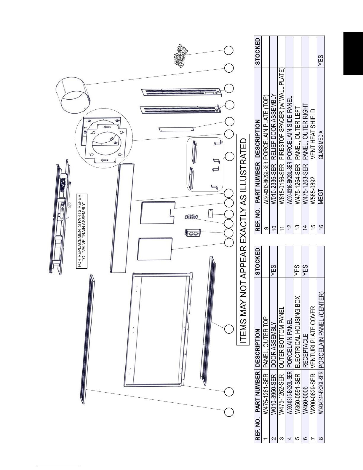
OUTER TOP PANEL
W290-0335
OUTER TOP PANEL
PART NUMBER
DESCRIPTION
DESCRIPTION
STOCKED
12
131415
16
W010-3950-SER
W010-2336-SER
W475-1261-SER
W585-0892
W615-0156-SER
W350-0591-SER
W090-0313-BK2GL-SER
W475-1262-SER
ELECTRICAL HOUSING BOX
PORCELAIN PLATE (TOP)
PORCELAIN PANEL (CENTER)
OUTER BOTTOM PANEL
W475-1263-SER
GLASS MEDIA
MEGT
YES
YES
W090-0316-BK2GL-SER
W090-0315-BK2GL-SER
1 2 3 4
5 6
7 8
9
10
11
12 13
14 15
16
43
EN
11.1 OVERVIEW
W415-1606 / 09.09.16
Page 44

EN
OUTER TOP PANELOUTER TOP PANEL
345
REF. NO.
1
STOCKED
STOCKED
9
PILOT ASSEMBLY (NG)
2
W585-0890-SER
FLEX CONNECTOR (w/ VALVE)
W456-0040
BURNER ASSEMBLY (NG)
YES
YES
1
PILOT ASSEMBLY (P)
3
3
BURNER ASSEMBLY (P)
4
YES
6
7
W445-0038
W725-0056
VALVE, S.I.T. ELEC (NG)
YES
YES
8
9
GK48
GAS MANIFOLD
W725-0057
VALVE, S.I.T. ELEC (P)
YES
BURNER ORIFICE #54
W456-0054
1 8
4
2
5
3 7
6
44
11.2 VALVE TRAIN ASSEMBLY
W415-1606 / 09.09.16
Page 45

REF. NO.
DESCRIPTION
3
REF. NO.
DESCRIPTION
2
1
STOCKED
STOCKED
4
5
SIDE TRIM (L/R), BLACK
W715-1112-SER
SAFETY SCREEN
SAFETY SCREEN
TOP/BOTTOM TRIM, STAINLESS STEEL
45
EN
12.0 ACCESSORIES
3 4 5
2
1
W415-1606 / 09.09.16
Page 46

46
WARNING
ALWAYS LIGHT THE PILOT WHETHER FOR THE FIRST TIME OR IF THE GAS SUPPLY HAS RUN OUT,
13.0 TROUBLESHOOTING
EN
!
WITH THE GLASS DOOR OPEN OR REMOVED.
TURN OFF THE GAS AND ELECTRICAL POWER BEFORE SERVICING THE APPLIANCE.
APPLIANCE MAY BE HOT, DO NOT SERVICE UNTIL APPLIANCE HAS COOLED.
DO NOT USE ABRASIVE CLEANERS.
SYMPTOM PROBLEM TEST SOLUTION
Pilot will not light.
Makes noise with
no spark at pilot
burner.
IGNITOR
(SPARK)
SENSOR
PILOT
TUBE
Pilot sparks but
will not light.
Carbon is being
deposited on
glass, logs,
rocks, media
or combustion
chamber surfaces.
Wiring. - Verify the wire for the sensor and the wire for the ignitor are
connected to the correct terminals (not reversed) on the
module. NOTE: Sensor has 3/16” (4.8mm) connection
and ignitor has 1/8” (3.2mm)connection.
Loose connection. - Verify no loose connections, electrical shorts in the wiring
or ground out to any metal object.
Module. - Turn the ON/OFF switch to the “OFF” position. Remove
the igniter wire from the module. Place the ON/OFF switch
to the “ON” position. Hold a grounded wire about 3/16”
(4.8mm) away from the ignitor (spark) terminal on the
module. If no spark the ignitor terminal module must be
replaced. If there is a spark the ignitor terminal is fi ne.
Inspect pilot assembly for a shorted wire or cracked
insulator around the electrode.
Igniter Spark gap is incorrect. - Spark gap of the ignitor to the pilot should be 1/8” (3.2mm).
Transformer. - Verify the transformer is installed and plugged into the
module. Check voltage of the transformer under load at
the spade connections on the module with the ON/OFF
switch in the “ON” position. Acceptable readings of a good
transformer are between 6.2 and 7.0 volts A.C.
Battery backup (if power is
off)
A shorted or loose
Connection.
Improper switch wiring. - Troubleshoot the system with the simplest ON/OFF switch.
Module is not grounded. - Verify the valve and pilot assemblies are properly grounded to
Gas supply. - Verify that the incoming gas line ball valve is “Open”. Verify
Out of propane gas. - Fill the tank.
Air shutter has become
blocked.
Flame is impinging on the
glass, logs, rocks, media or
combustion chamber.
- Check batteries.
- Remove and reinstall the wiring harness that plugs into the
module. Remove and verify continuity of each wire in wiring
harness.
the metal chassis of the appliance or log set.
that the inlet pressure reading is within acceptable limits,
inlet pressures must not exceed 13” W.C. (32.3mb).
- Ensure air shutter opening is free of lint or other
obstructions.
- Check that the glass, logs, rocks or media are correctly positioned.
- Too much glass media around the burner can cause carbon deposits.
- Open air shutter to increase the primary air.
- Check the input rate: check the manifold pressure and
orifi ce size as specifi ed by the rating plate values.
- Check that the door gasketing is not broken or missing and
that the seal is tight.
- Check that both vent liners are free of holes and well
sealed at all joints.
- Check that minimum rise per foot has been adhered to for
any horizontal venting.
42.7B
W415-1606 / 09.09.16
Page 47

SYMPTOM PROBLEM TEST SOLUTION
increase the fl ame rectifi cation. Verify correct pilot orifi ce is
Continues to spark
and pilot lights, but
main burner will not
light.
Pilot lights
Stops sparking
/ pilot remains lit
but burner will
not turn on.
Exhaust fumes
smelled in room,
headaches.
White / grey fi lm
forms.
Flames are very
aggressive.
Main burner fl ame
is a blue, lazy,
transparent
fl ame.
Main burner goes
out: pilot goes out.
Short or loose
connection in sensor rod.
Poor fl ame rectifi cation
or contaminated
sensor rod.
Poor grounding between
pilot assembly and
gas valve.
Damaged pilot or dirty
sensor rod.
Wiring / Connection. - Inspect all wires, ensure good tight connections. Verify
Wiring harness. - Inspect the wiring harness, and verify the harness is
Appliance is spilling. - Check all seals.
Sulphur from fuel is being
deposited on glass, logs or
combustion chamber
surfaces.
Door is ajar. - Tighten door clamps if applicable.
Venting action is too great. - Restrict vent exit with restrictor plate. See
Blockage in vent. - Remove blockage. In extreme conditions, ice buildup
Compromised venting.
Vent recirculation. - Check joint seals and installation.
- Verify all connections. Verify the connections from the
pilot assembly are tight; also verify these connections are
not grounding out to any metal.
- Verify the fl ame is engulfi ng the sensor rod. This will
installed and inlet gas specifi cations to manual. (Remember,
the fl ame carries the rectifi cation current, not the gas. If the
fl ame lifts from pilot hood, the circuit is broken. A wrong
orifi ce or to high of an inlet pressure can cause the pilot
fl ame to lift.) The sensor rod may need cleaning.
- Verify that the wire harness is fi rmly connected to module.
Verify that the ceramic insulator around the sensor rod is
not cracked, damaged, or loose. Verify the connection from
the sensor rod to the sensor wire.
- Clean sensor rod with a fi ne emery cloth or synthetic
scrub pad to remove any contamination that may have
accumulated on the sensor rod. Verify continuity with
multimeter with ohms set at the lowest range.
that all wiring is installed exactly as specifi ed.
tightly connected to the module. Verify that all wires are
connected in the right order. See “WIRING DIAGRAM”
section.
- Check if exhaust is re-entering through an open door or
window.
- Clean the glass, see “CARE OF GLASS” section
- DO NOT CLEAN GLASS WHEN HOT.
- If deposits are not cleaned off regularly, the glass may
become permanently marked.
“RESTRICTING VENTS” section if applicable.
may occur on the terminal and should be removed. To
minimize this from happening again, it is recommended
that the vent lengths that pass through unheated
spaces (attics, garages, crawl spaces) be wrapped
with an insulated mylar sleeve. Prevent sleeve from
sagging. Contact your local authorized dealer for more
information.
- Check venting system parameters (seal, length, rise, etc.).
47
EN
42.7_2A
W415-1606 / 09.09.16
Page 48

48
NAPOLEON products are manufactured under the strict Standard of the world recognized ISO 9001 : 2008 Quality
14.0 WARRANTY
EN
NAPOLEON products are designed with superior components and materials assembled by trained craftsmen who take
Assurance Certifi cate.
great pride in their work. The burner and valve assembly are leak and test-fi red at a quality test station. The complete
appliance is again thoroughly inspected by a qualifi ed technician before packaging to ensure that you, the customer,
receives the quality product that you expect from NAPOLEON.
NAPOLEON GAS APPLIANCE PRESIDENT’S LIFETIME LIMITED WARRANTY
The following materials and workmanship in your new NAPOLEON gas appliance are warranted against defects for
as long as you own the appliance. This covers: combustion chamber, heat exchanger, stainless steel burner, phazer™
logs and embers, rocks, ceramic glass (thermal breakage only), gold plated parts against tarnishing, porcelainized
enameled components and aluminum extrusion trims.*
Electrical (110V and millivolt) components and wearable parts are covered and NAPOLEON will provide replacement
parts free of charge during the fi rst year of the limited warranty. This covers: blowers, gas valves, thermal switches,
switches, wiring, remote controls, ignitors, gaskets and pilot assemblies.*
Labour related to warranty repair is covered free of charge during the fi rst year. Repair work, however, requires
the prior approval of an authorized company offi cial. Labour costs to the account of NAPOLEON are based on a
predetermined rate schedule and any repair work must be done through an authorized NAPOLEON dealer.
* Construction of models vary. Warranty applies only to components included with your specifi c appliance.
CONDITIONS AND LIMITATIONS
NAPOLEON warrants its products against manufacturing defects to the original purchaser only. Registering your warranty is not
necessary. Simply provide your proof of purchase along with the model and serial number to make a warranty claim. NAPOLEON
reserves the right to have its representative inspect any product or part thereof prior to honouring any warranty claim. Provided
that the purchase was made through an authorized NAPOLEON dealer your appliance is subject to the following conditions and
limitations:
Warranty coverage begins on the date of original installation.
This factory warranty is non-transferable and may not be extended whatsoever by any of our representatives.
The gas appliance must be installed by a licensed, authorized service technician or contractor. Installation must be done in
accordance with the installation instructions included with the product and all local and national building and fi re codes.
This limited warranty does not cover damages caused by misuse, lack of maintenance, accident, alterations, abuse or neglect and
parts installed from other manufacturers will nullify this warranty.
This limited warranty further does not cover any scratches, dents, corrosion or discoloring caused by excessive heat, abrasive and
chemical cleaners nor chipping on porcelain enamel parts, mechanical breakage of PHAZER™ logs and embers.
This warranty extends to the repair or replacement of warranted parts which are defective in material or workmanship provided that
the product has been operated in accordance with the operation instructions and under normal conditions.
After the fi rst year, with respect to this President’s Lifetime Limited Warranty, NAPOLEON may, at its discretion, fully discharge all
obligations with respect to this warranty by refunding to the original warranted purchaser the wholesale price of any warranted but
defective part(s).
NAPOLEON will not be responsible for installation, labour or any other expenses related to the reinstallation of a warranted part and
such expenses are not covered by this warranty.
Notwithstanding any provisions contained in the President’s Lifetime Limited Warranty, NAPOLEON’S responsibility under this
warranty is defi ned as above and it shall not in any event extend to any incidental, consequential or indirect damages.
This warranty defi nes the obligations and liability of NAPOLEON with respect to the NAPOLEON gas appliance and any other
warranties expressed or implied with respect to this product, its components or accessories are excluded.
NAPOLEON neither assumes, nor authorizes any third party to assume, on its behalf, any other liabilities with respect to the sale of
this product.
NAPOLEON will not be responsible for: over-fi ring, downdrafts, spillage caused by environmental conditions such as rooftops,
buildings, nearby trees, hills, mountains, inadequate vents or ventilation, excessive venting confi gurations, insuffi cient makeup air, or
negative air pressures which may or may not be caused by mechanical systems such as exhaust fans, furnaces, clothes dryers, etc.
Any damages to the appliance, combustion chamber, heat exchanger, plated trim or other components due to water, weather
damage, long periods of dampness, condensation, damaging chemicals or cleaners will not be the responsibility of NAPOLEON.
All parts replaced under the President’s Limited Lifetime Warranty Policy are subject to a single claim.
During the fi rst 10 years NAPOLEON will replace or repair the defective parts covered by the lifetime warranty at our discretion free of
charge. From 10 years to life, NAPOLEON will provide replacement parts at 50% of the current retail price.
All parts replaced under the warranty will be covered for a period of 90 days from the date of their installation.
The manufacturer may require that defective parts or products be returned or that digital pictures be provided to support the
claim. Returned products are to be shipped prepaid to the manufacturer for investigation. If a product is found to be defective, the
manufacturer will repair or replace such defect.
Before shipping your appliance or defective components, your dealer must obtain an authorization number. Any merchandise
shipped without authorization will be refused and returned to sender.
Shipping costs are not covered under this warranty.
Additional service fees may apply if you are seeking warranty service from a dealer.
Warranty labour allowance is only for the replacement of the warranted part. Travel, diagnostic tests, shipping and other related
charges are not covered by this warranty.
ALL SPECIFICATIONS AND DESIGNS ARE SUBJECT TO CHANGE WITHOUT PRIOR NOTICE DUE TO ON-GOING PRODUCT
IMPROVEMENTS. NAPOLEON IS A REGISTERED TRADEMARK OF WOLF STEEL LTD.
W415-1606 / 09.09.16
2.1D
Page 49

15.0 SERVICE HISTORY
49
EN
43.1
W415-1606 / 09.09.16
Page 50

EN
50
16.0 NOTES
W415-1606 / 09.09.16
44.1
Page 51

44.1
Page 52

Products
®
Other Napoleon
Fireplace Inserts • Charcoal Grills • Gas Fireplaces • Waterfalls • Wood Stoves
Heating & Cooling • Electric Fireplaces • Outdoor Fireplaces • Gas Grills
24 Napoleon Road, Barrie, Ontario, Canada L4M 0G8
214 Bayview Drive, Barrie, Ontario, Canada L4N 4Y8
103 Miller Drive, Crittenden, Kentucky, USA 41030
7200 Trans Canada Highway, Montreal, Quebec, Canada H4T 1A3
Fireplaces / Heating & Cooling call: 705-721-1212 • Grills call: 705-726-4278
napoleonproducts.com
 Loading...