

Page 1
INSTALLER: THESE INSTRUCTIONS ARE TO REMAIN WITH THE HOME OWNER.
Wolf Steel Ltd., 24 Napoleon Rd., Barrie, ON L4M 0G8 Canada • 1(866)820-8686 • www.napoleonreplaces.com
CHECK THE BOXES TO INDICATE THAT THE CORRESPONDING STEPS HAVE BEEN COMPLETED.
FUEL CONVERSION KITS FOR MODELS LV38-1 / LV50-2 / LV62
These kits are for use at altitudes of 0 to 4,500 feet.
Kit W175-0642, Natural Gas to Propane Includes;
1 Regulator
1 #53 Burner orifice
1 Propane burner tube
Kit W175-0644, Natural Gas to Propane Includes;
1 Regulator
1 #52 Burner orifice
1 Propane burner tube
Kit W175-0646, Natural Gas to Propane Includes;
1 Regulator
1 #51 Burner orifice
1 Propane burner tube
This conversion kit shall be installed by a qualified service agency in accordance with the manufacturer’s instructions
and all applicable codes and requirements of the authority having jurisdiction. If the information in these instructions
is not followed exactly, a fire, explosion or production of carbon monoxide may result causing property damage,
personal injury or loss of life. The qualified service agency is responsible for the proper installation of this kit. The
installation is not proper and complete until the operation of the converted appliance is checked as specified in the
owner instructions supplied with the kit.
WARNING: Failure to position the parts in accordance with these diagrams or failure to use only parts specifically
approved with this appliance may result in property damage or personal injury.
CAUTION: Before proceeding with conversion the gas supply must be shut off prior to disconnecting the electrical power.
important:
We strongly recommend converting your appliance prior to final installation and removing porcelain panels for conversion.
LV38-1
LV50-2
LV62
1 Propane pilot injector
1 Conversion data label
1 Air shutter adjustment rod
1 Propane pilot injector
1 Conversion data label
1 Air shutter adjustment rod
1 Propane pilot injector
1 Conversion data label
1 Air shutter adjustment rod
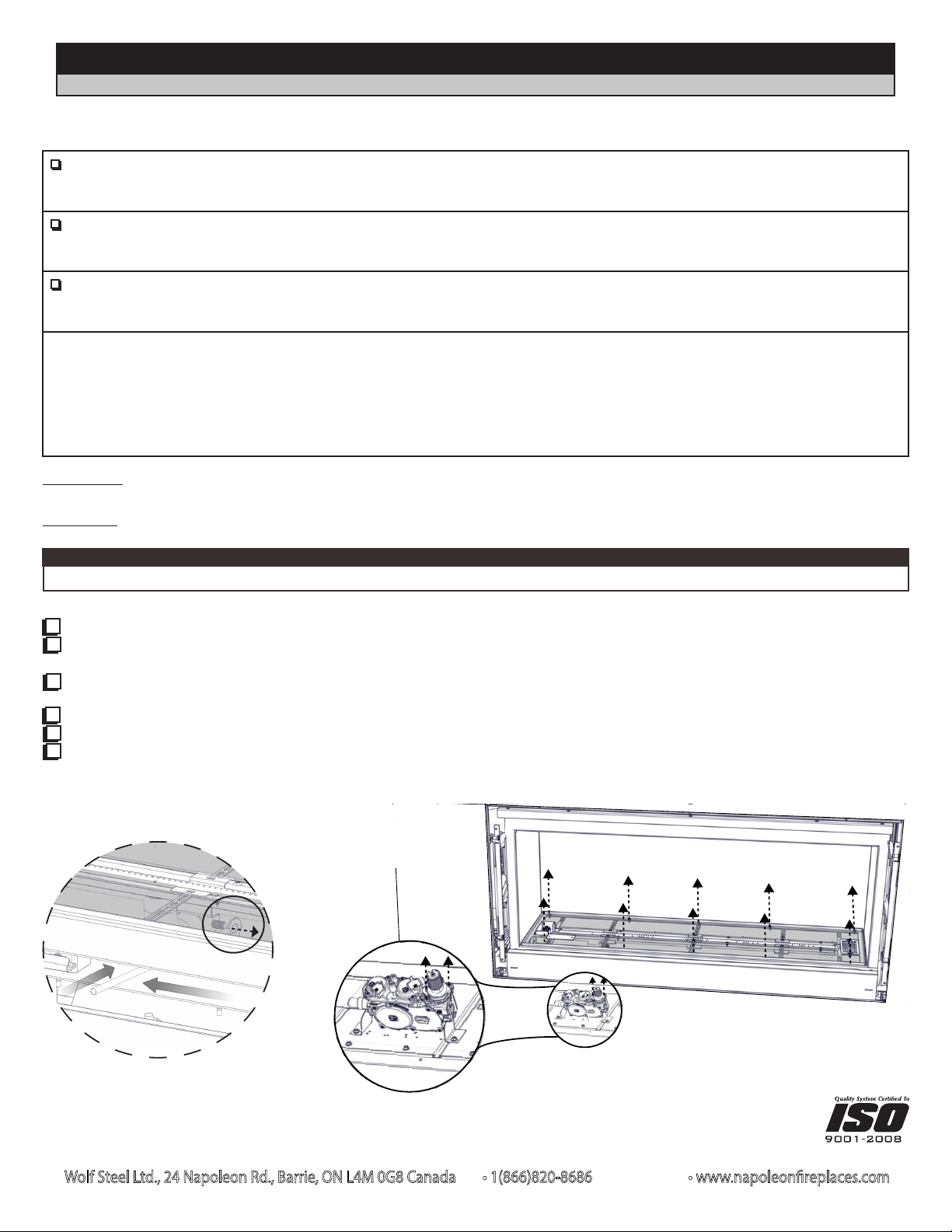
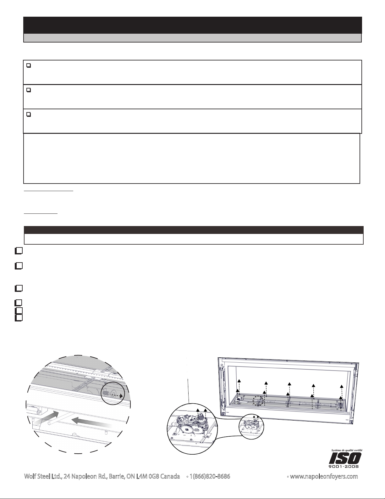
1. Remove the safety barrier, door trim and glass door. Remove existing media and media trays. Set aside.
2. Disengage the air shutter adjustment rod by pushing the smaller end of the rod to the left then push towards the back of
the appliance until the rod clears the rubber grommet (Fig. 1). The rubber grommet must stay in place.
3. Remove the screws that secure the entire burner assembly in place (screw counts vary by appliance size) (Fig. 2). Lift the
entire burner assembly up and out of the appliance. Remove the air shutter adjustment rod. Set both aside.
4. Using a deep socket wrench, remove the orifice from within the firebox and replace with the orifice supplied.
5. Remove the two screws from the valve regulator and remove the regulator, replace with the one supplied (Fig. 2).
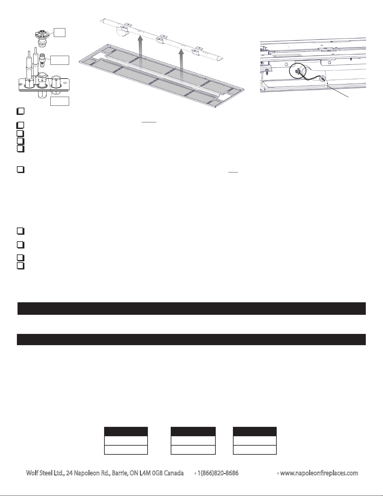
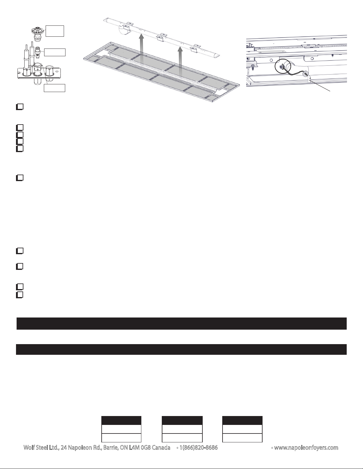
6. Remove the pilot spring clip then the pilot hood from the pilot assembly by pulling vertically. Use a 5/32” Allen key to
unscrew the injector. Replace the pilot injector with the one supplied (Fig. 3). Re-assemble the pilot hood onto the
assembly and reattach the spring clip ensuring key position for proper alignment.
Figure 1
Figure 2
LV38-1 illustrated.
W415-1782 / B / 09.28.17
Page 2
PILOT
HOOD
PILOT
INJECTOR
SPRING
CLIP
Figure 3 Figure 4
Wolf Steel Ltd., 24 Napoleon Rd., Barrie, ON L4M 0G8 Canada • 1(866)820-8686 • www.napoleonreplaces.com
Figure 5
Indicator label
7. Install the new air shutter adjustment rod (supplied) by sliding the smaller end through the rubber grommet from the inside
of the firebox. The rubber grommet must be seated correctly in order to properly seal the appliance.
8. Remove screws securing the old burner tube to the burner assembly (screw count varies by size of appliance) (Fig. 4).
9. Slide the new burner tube into place within the burner tray assembly and secure using the screws previously removed.
10. The conversion data label must be filled out and attached adjacent to the valve.
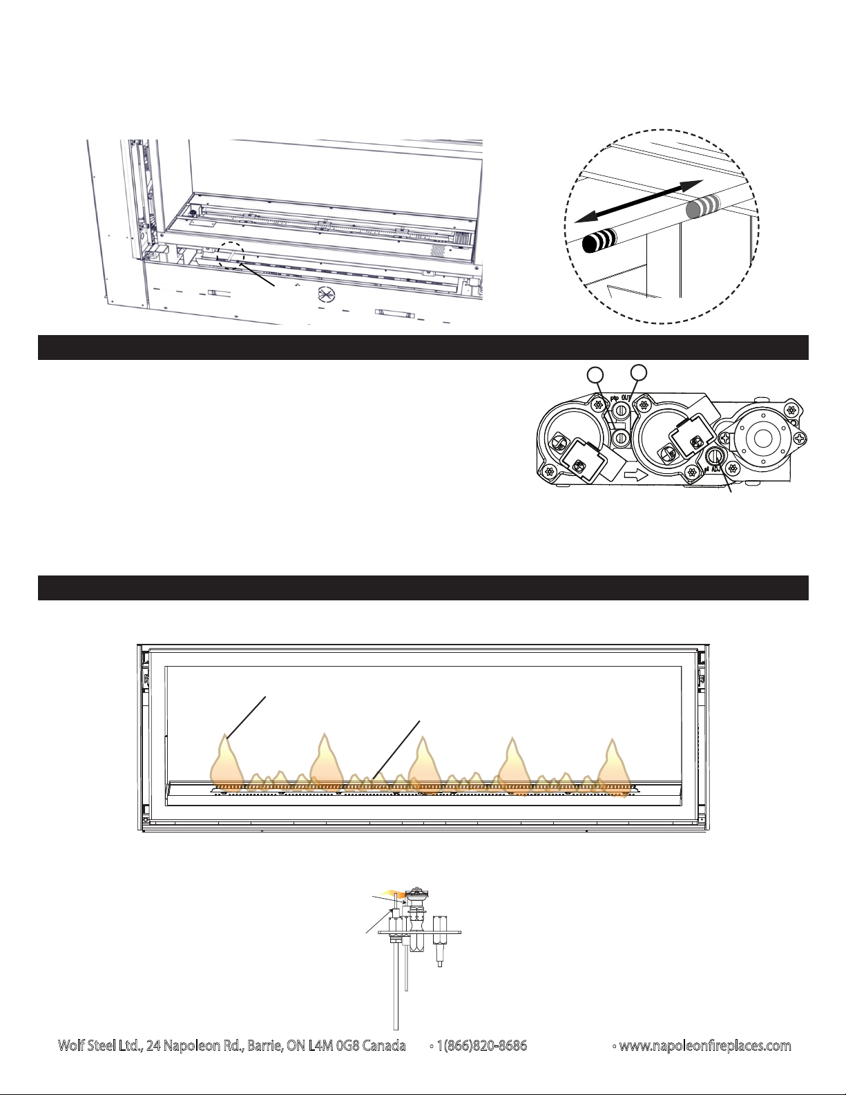
11. Position the burner assembly in place inside the firebox but do not secure. Lift the burner assembly up then manually
engage the larger end of the rod over the left side of the new air shutter. Ensure the rubber grommet is correctly
positioned around the air shutter stud (Fig. 5). Once fully engaged, secure the burner assembly.
12. Reinstall media trays, unless using sand as media. It is recommended not to reinstall the media trays for propane
applications with other media types. Not only will this provide a clean look to the appliance, but it also results in a more
pleasing and clean burning flame. Media trays should be stored in the event it is planned to install alternate media at
some point in the future. Media should be installed evenly across the burner tray and a moderate amount of media placed
on the burner itself and, if necessary, adjusted to achieve a pleasing flame appearance. Never place excessive media
on the burner as this can result in carboning or an unappealing flame characteristic. Never place media in the
pilot housing or over the pilot. Always check that the appliance ignites smoothly across the entire burner to ensure
media does not compromise performance. Pay particular attention when using power vents to ensure media placement
does not affect ignition or flame characteristics. Adjust the air shutter according to the table under “venturi adjustment”.
13. Turn on the electrical supply to the appliance. Turn on the gas supply. Then light the pilot to ensure the gas lines have been
purged.
14. Check for gas leaks by brushing on a soap and water solution. Refer to the lighting instructions in your installation
manual. Do not use open flame. Once all systems have been checked, reinstall old media.
15. Install indicator label (supplied) onto the end of air shutter adjustment rod (Fig. 5).
16. Reinstall the glass door, trim, and safety barrier.
Purge all gas lines with the glass door off.
Assure that a continuous flow is at the burner before replacing the glass door and safety barrier.
ADJUSTMENTS
NOTE: Your appliance may be equipped with either a rotating or a sliding air shutter cap.
VENTURI ADJUSTMENT
EXTERNALLY ADJUSTABLE AIR SHUTTER
This appliance is equipped with an externally adjustable air shutter that is not preset from factory. Any adjustment will be required
after any change to the appliance. Any adjustments made to the shutter must be done with the burner and all media installed into
the unit. It is important to operate the unit and verify that the air shutter is opened to the correct amount to prevent either flame
lifting or carbonization. To open and close the shutter, pull the knob away from the unit and push the knob towards the appliance
respectively.
Small adjustments on the shutter can have a drastic effect on the flame appearance; it is recommended to adjust the shutter in
1/8” increments.
LV38-1
P
1/4” (6.4mm)
LV50-2
P
5/16” (8mm)
LV62
P
5/16” (8mm)
Page 3
Wolf Steel Ltd., 24 Napoleon Rd., Barrie, ON L4M 0G8 Canada • 1(866)820-8686 • www.napoleonreplaces.com
OPEN
CLOSE
WARNING: AIR SHUTTER ADJUSTMENT MUST BE DONE BY A QUALIFIED INSTALLER.
A
B
PILOT SCREW
Closing the air shutter will cause a more yellow flame, but can lead to carboning. Opening the air shutter will cause a more blue
flame, but can cause flame lifting from the burner ports. The flame may not appear yellow immediately; allow 15 to 30 minutes
for the final flame colour to be established.
AIR SHUTTER
ADJUSTMENT
PRESSURE ADJUSTMENT
Adjust the pilot screw to provide properly sized flame. Turn in a clockwise direction
to reduce the gas flow.
Inlet pressure can be checked by turning screw (A) counter-clockwise until loosened
and then placing pressure gauge tubing over the test point. Gauge should read 7”
(minimum 4.5”) water column for natural gas or 13” (11” minimum) water column for
propane. Check that main burner is operating on “HI”.
Outlet pressure can be checked the same as above using screw (B). Gauge should
read 3.5” water column for natural gas or 10” water column for propane. Check that
main burner is operating on “HI”.
AFTER TAKING PRESSURE READINGS, TIGHTEN SCREWS FIRMLY TO SEAL. DO NOT OVER TORQUE.
LEAK TEST
FLAME CHARACTERISTICS
It’s important to periodically perform a visual check of the pilot and burner flames. Compare them to the illustrations provided.
Peak
Valley
PILOT
ELECTRODE
FLAME
SENSOR
BURNER
FLAME MUST ENVELOP
UPPER 3/8” TO 1/2” OF
FLAME SENSOR
Page 4
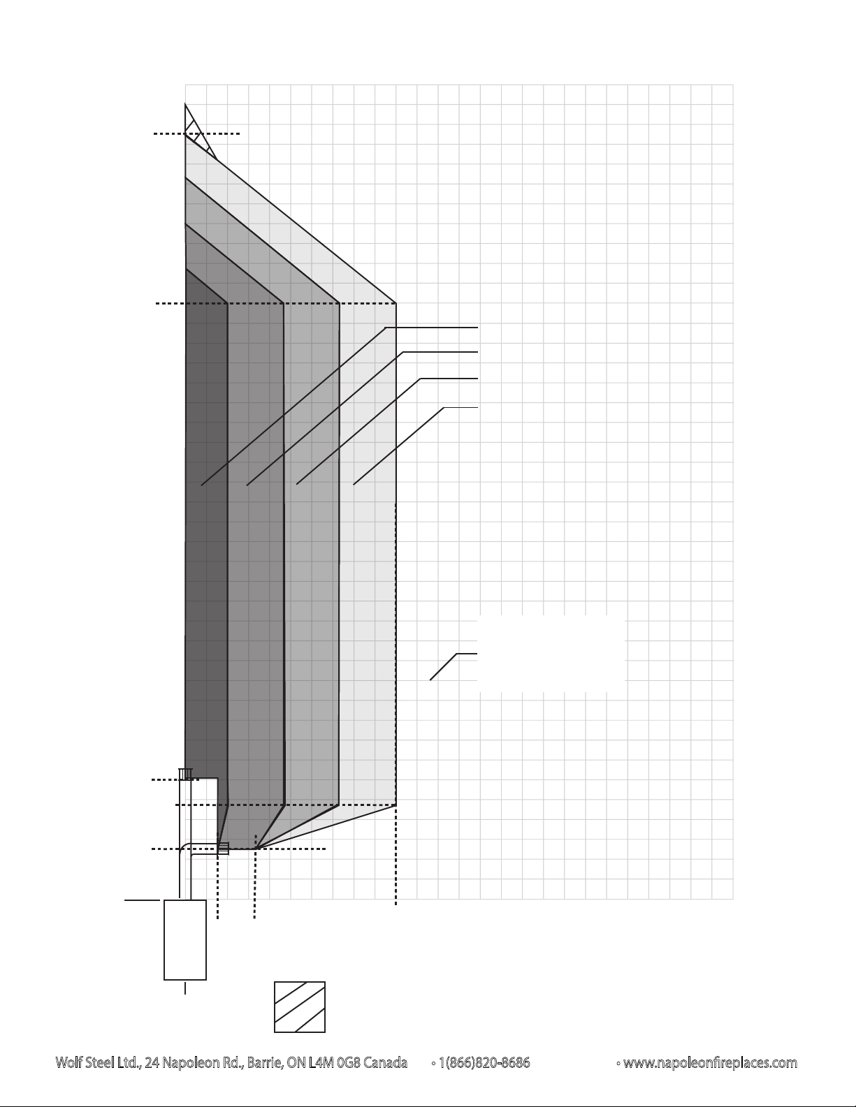
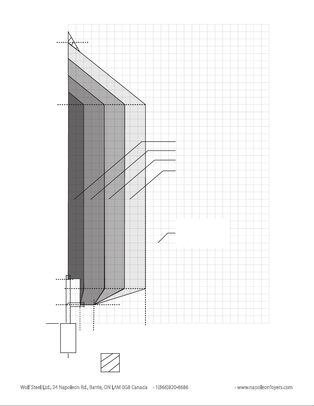
LV38-1 venting configurations (P)
Wolf Steel Ltd., 24 Napoleon Rd., Barrie, ON L4M 0G8 Canada • 1(866)820-8686 • www.napoleonreplaces.com
38 1/2’
(462”)
30’
V
40’
20’
V+H ≤ 40 ft. H ≤ 10 ft.
(For longer vent runs, a power vent is
required).
V + H are measured from the centre of vent
elbows. Elbows are considered as 90º.
Two 45º elbows = One 90º elbow.
For 0 elbow configurations, V is a minimum
of 6’ to a maximum of 40’.
1-4 elbow zone
1-3 elbow zone
1-2 elbow zone
1 elbow zone
6’
(72”)
4 3/4’
(57”)
2 1/2’
(30”)
0’
Base of
air collar
5’
15’
10’
Refer to appliance
specific GPV/PVA
instructions for other
venting configurations.
1 1/2’
(18”)
5’
3 1/4’
(40”)
10’
H
15’
20’
25’
Vertical termination only.
0’
No horizontal termination allowed.
Page 5

LV50-2 / LV62 venting configurations (P)
Wolf Steel Ltd., 24 Napoleon Rd., Barrie, ON L4M 0G8 Canada • 1(866)820-8686 • www.napoleonreplaces.com
40’
38 ½’
(462”)
35’
V
V+H ≤ 40 ft. H ≤ 4⅜ ft.
(For longer vent runs, a power vent is
required).
V + H are measured from the centre of vent
elbows. Elbows are considered as 90º.
Two 45º elbows = One 90º elbow.
For 0 elbow configurations, V is a minimum
of 6’ to a maximum of 40’.
30’
1-2 elbow zone
1 elbow zone
20’
8 ½’
(102”)
6’
(72”)
4’
(48”)
0’
Base of
air collar
15’
10’
5’
Refer to appliance
specific GPV/PVA
instructions for other
venting configurations.
1 ½’
(18”)
2 ½’
(30”)
0’
5’
4 ⅜’
(52 ½”)
3 ⅞’
(46 ½”)
Vertical termination only.
10’
H
15’
20’
25’
No horizontal termination allowed.
Page 6
INSTALLATEUR : CES INSTRUCTIONS DOIVENT ÊTRE GARDÉES PAR LE PROPRIÉTAIRE.
Wolf Steel Ltd., 24 Napoleon Rd., Barrie, ON L4M 0G8 Canada • 1(866)820-8686 • www.napoleonfoyers.com
VEUILLEZ COCHER LES CASES POUR INDIQUER QUE LES ÉTAPES CORRESPONDANTES ONT ÉTÉ COMPLÉTÉES.
ENSEMBLE DE CONVERSION POUR LES MODÈLES LV38-1 / LV50-2 / LV62
Cet ensemble est utilisé pour des altitudes de 0 à 4 500 pieds.
L’ensemble W175-0642, de gaz naturel à propane comprend:
1 Régulateur
1 #53 Injecteur de brûleur
1 Brûleur tubulaire (P)
L’ensemble W175-0644, de gaz naturel à propane comprend:
1 Régulateur
1 #52 Injecteur de brûleur
1 Brûleur tubulaire (P)
L’ensemble W175-0646, de gaz naturel à propane comprend:
1 Régulateur
1 #51 Injecteur de brûleur
1 Brûleur tubulaire (P)
Cet ensemble de conversion doit être installé par une agence d’entretien qualifiée conformément aux instructions du
fabricant et à tous les codes et les exigences des autorités compétentes. Si ces instructions ne sont pas suivies à la
lettre, un incendie, une explosion ou une production de monoxyde de carbone pourrait s’ensuivre, causant des dommages
matériels, des blessures corporelles ou des pertes de vie. L’agence d’entretien est responsable de l’installation adéquate
de cet ensemble. L’installation n’est pas considérée complète ni adéquate jusqu’à ce que le fonctionnement de l’appareil
converti soit vérifié et jugé conforme aux instructions fournies avec cet ensemble.
AVERTISSEMENT : Omettre de positionner les pièces conformément aux schémas de ce feuillet ou omettre d’utiliser
uniquement des pièces spécifiquement approuvées pour cet appareil peut causer des dommages matériels ou des
blessures corporelles.
ATTENTION : Avant d’effectuer la conversion, vous devez couper l’alimentation en gaz avant de couper l’alimentation
électrique.
LV38-1
LV50-2
LV62
1 Injecteur de veilleuse (P)
1 Étiquette de données de conversion
1 Tige de contrôle d’air
1 Injecteur de veilleuse (P)
1 Étiquette de données de conversion
1 Tige de contrôle d’air
1 Injecteur de veilleuse (P)
1 Étiquette de données de conversion
1 Tige de contrôle d’air
important:
Il est recommandé de convertir l’appareil avant l’installation final et d’enlever les panneaux en porcelain avant de convertir.
1. Retirez l’écran de protection, la garniture de porte et la porte vitrée. Retirez les composants décoratifs et les plateaux.
Misez-les au côté.
2. Dégagez la tige de contrôle en poussant la côté la plus petit de la tige vers la gauche puis poussez-la vers l’arrière de
l’appareil jusqu’elle défriche le passe-câble en caoutchouc (Fig. 1). Le passe-câble en caoutchouc doit rester en
place.
3. Retirez les vis servant à fixer l’assemblage du brûleur en place (le nombre de vis varies par appareil) (Fig. 2). Soulevez
l’assemblage du brûleur vers le haut et hors de l’appareil. Soulevez la tige de contrôle. Misez-les au côté.
4. En utilisant une clé à douille profonde, retirez l’injecteur de l’intérieur de l’appareil et le remplacer par l’injecteur fourni.
5. Retirez les deux vis servant à fixer le régulateur du soupape et retirer le régulateur, remplacez par celui fourni (Fig. 2).
6. Retirez la pince à ressort de la veilleuse puis la hotte de la veilleuse de l’assemblage de la veilleuse en tirant à la verticale.
Utilisez une clé Allen de 5/32” pour dévisser l’injecteur. Remplacez l’injecteur par celui qui est fourni (Fig. 3). Replacez la
hotte de dérivation de flamme sur l’assemblage de la veilleuse et rattacher la pince à ressort en vous assurant qu’elle est
bien alignée.
Figure 1
Figure 2
LV38-1 illustré.
W415-1782 / B / 09.28.17
Page 7
HOTTE DE
DÉRIVATION
DE FLAMME
INJECTEUR
DE VEILLEUSE
PINCE À
RESSORT
Figure 3
Wolf Steel Ltd., 24 Napoleon Rd., Barrie, ON L4M 0G8 Canada • 1(866)820-8686 • www.napoleonfoyers.com
Figure 4
Figure 5
Plaque d’indication
7. Installez la nouvelle tige de contrôle (fourni) par glissez la côté la plus petit à travers le passe-câble en caoutchouc par
l’intérieur du chambre de combustion. Le passe-câble en caoutchouc doit être bien placer afin d’assurer que
l’appareil est scellé correctement.
8. Retirez les vis fixant l’ancien brûleur tubulaire à l’assemblage du brûleur (le nombre de vis varies par appareil) (Fig. 4).
9. Glissez la nouvelle brûleur tubulaire en place dedans l’assemblage du brûleur et fixez-le utilisant les vis auparavant enlever.
10. L’étiquette de données de conversion doit être remplie et fixée adjacente à la soupape.
11. Positionnez l’assemblage du brûleur en place dedans le chambre de combustion. Ne fixez pas. En soulevant
l’assemblage vers le haut, engagez le partie la plus grand de la tige de contrôle d’air manuellement sur la côté droite du
volet d’air. Assurez-vous que le passe-câble en caoutchouc est correctement positionner autour d’étalon du volet d’air
(Fig. 5). Lorsqu’elle est complètement engager, sécurisez l’assemblage du brûleur.
12. Réinstallez les plateaux, à moins qu’avec du sable comme les médias. Il est recommandé ne pas de réinstaller les plateaux
pour des applications de propane avec d’autres types de médias. Cela fournira un regard propre à l’appareil et il se traduit
également par une flamme plus agréable et propre combustion. Les plateaux devrait être conservés dans le cas où il est
prévu d’installer d’autres médias ensuite. Médias doivent être installés uniformément à travers le plateau du brûleur et une
quantité modérée de médias placée sur le brûleur lui-même et, si nécessaire, ajustée pour obtenir un aspect plaisant de la
flamme. Ne placez jamais médias excessive sur le brûleur car cela peut entraîner les dépôts de carbone ou une
caractéristique désagréable de la flamme. Ne jamais placer des médias dans le boîtier de la veilleuse ou sur
la veilleuse. Toujours vérifier que l’appareil s’allume sans à-coup à travers l’ensemble brûleur à s’assurer que les médias
ne compromet pas la performance. Accorder une attention particulière lors de l’utilisation des terminaison mécaniques afin
d’assurer le placement média n’affecte pas les caractéristiques d’allumage ou de flamme. Changez le réglage du volets
d’air en vous référant au tableau dessous.
13. Rétablissez l’alimentation électrique au l’appareil puis l’alimentation en gaz. Ensuite, allumez la veilleuse et le brûleur pour
vous assurer que les conduites de gaz ont été purgées.
14. Vérifiez pour des fuites de gaz en appliquant une solution d’eau savonneuse. Référez-vous aux instructions d’allumage
dans votre manuel d’installation pour votre foyer. Ne pas utiliser de flamme nue. Une fois que tous les systèmes ont été
inspectés, remettez les médias existant.
15. Installez la plaque d’indication (fournie) sur le but du tige de contrôle (Fig. 5).
16. Réinstallez le porte vitrée, la garniture de porte et l’écran de protection.
Purgez toutes les conduites de gaz avec la porte vitrée ouverte. Assurez-vous que l’arrivée de gaz au brûleur est
continue avant de remettre la vitre avant.
RÉGLAGES
REMARQUE: Cette appareil peut être fourni avec une bouchon d’obturation tournant ou glissant.
RÉGLAGE DU VENTURI
Cet appareil est muni d’un volet d’air à réglage externe qui n’est pas préréglé en usine. Il est situé à la gauche de l’appareil,
au-dessus de la soupape. Les réglages du volet d’air doivent être effectués lorsque le brûleur et les braises vitrifiées sont installés
dans l’appareil. Il est important de faire fonctionner l’appareil pour s’assurer que le volet d’air est bien ajusté afin d’éviter que la
flamme se détache des orifices du brûleur ou des dépôts de carbone. Pour ouvrir et fermer le volet d’air, tirez le bouton vers vous
pour l’ouvrir et poussez-le pour le fermer.
Tout réglage mineur apporté au volet peut avoir une incidence considérable sur l’aspect de la flamme. Il est recommandé de régler
le volet par tranche de 1/8 po.
LV38-1
P
1/4” (6.4mm)
LV50-2
P
5/16” (8mm)
LV62
P
5/16” (8mm)
Page 8

Wolf Steel Ltd., 24 Napoleon Rd., Barrie, ON L4M 0G8 Canada • 1(866)820-8686 • www.napoleonfoyers.com
AVERTISSEMENT: LE RÉGLAGE DU VOLET D’AIR DOIT ÊTRE EXÉCUTÉ PAR UN TECHNICIEN OU INSTALLEUR QUALIFIÉ
A
B
VIS DE LA VEILLEUSE
OPEN
CLOSE
VEILLEUSE
LA FLAMME DOIT
ENVELOPPER LA PARTIE
SUPÉRIEURE DU
THERMOCOUPLE ET DE LA
THERMOPILE DE 3/8” À 1/2”.
SONDE
DE FLAMME
ÉLECTRODE
Plus le volet est fermé, plus la flamme est jaune et plus elle aura tendance à causer des dépôts de carbone. Plus le volet est
ouvert, plus la flamme est bleue et plus elle a tendance à se détacher des orifices du brûleur. La flamme peut ne pas être jaune
immédiatement; allouez de 15 à 30 minutes pour que la couleur finale de la flamme se stabilise.
FERMÉ
OUVERTE
RÉGLAGE DU
VOLET D’AIR
AJUSTEMENT DE LA PRESSION
Ajustez la vis de la veilleuse pour obtenir une flamme de taille normale. Tournez vers
la droite pour réduire l’apport de gaz.
Pour vérifier la pression d’arrivée, tournez la vis (A) vers la gauche jusqu’à ce qu’elle
soit desserrée, puis emboîtez le tube du manomètre sur la pointe d’essai. Le
manomètre doit indiquer 7” (minimum 4,5”) de colonne d’eau pour le gaz naturel ou
13” (11” minimum) de colonne d’eau pour le propane. Assurez-vous que le brûleur
principal fonctionne à « HI ».
La pression de sortie peut être vérifiée de la même façon en utilisant la vis (B). Le
manomètre doit indiquer 3,5” de colonne d’eau pour le gaz naturel ou 10” de colonne
d’eau pour le propane. Assurez-vous que le brûleur principal fonctionne à « HI ».
APRÈS AVOIR PRIS LA LECTURE DES PRESSIONS, SERREZ BIEN LES VIS POUR
SCELLER. NE SERREZ PAS TROP FORT.
VÉRIFIEZ POUR DES FUITES
CARACTÉRISTIQUES DES FLAMMES
Il est important d’effectuer périodiquement une inspection visuelle de la flamme de la veilleuse et du brûleur. Comparez-la à ces
illustrations.
Pic
Vallée
Page 9
Wolf Steel Ltd., 24 Napoleon Rd., Barrie, ON L4M 0G8 Canada • 1(866)820-8686 • www.napoleonfoyers.com
Configurations d’évacuation LV38-1 (P)
38 1/2’
(462”)
30’
V
40’
20’
V+H ≤ 40 pi. H ≤ 10 pi.
(Pour les courses horizontales longueurs, un terminaison mécanique
est requis).
V + H sont mesurés du centre à partir
du centre centre des coudes
d’évents. Les coudes sont considérés
comme 90º.
Deux coudes de 45º = Une coude de
90º.
Pour les configurations avec zéro
coude, V est un minimum de 6 pi à un
maximum de 40 pi.
Zone de coude 1 à 4
Zone de coude 1 à 3
Zone de coude 1 à 2
Zone de coude 1
6’
(72”)
4 3/4’
(57”)
2 1/2’
(30”)
0’
Base du
collet d’ air
5’
15’
10’
Référez aux instructions
de GPV/PVA spécifique
à votre appareil pour
d’autres configurations
d’évacuation.
1 1/2’
(18”)
5’
3 1/4’
(40”)
10’
H
15’
20’
25’
Seulement terminaison verticale.
0’
Aucun terminaison horizontale permis.
Page 10

Wolf Steel Ltd., 24 Napoleon Rd., Barrie, ON L4M 0G8 Canada • 1(866)820-8686 • www.napoleonfoyers.com
Configurations d’évacuation LV50-2 / LV62 (P)
40’
38 ½’
(462”)
35’
V
30’
20’
V+H ≤ 40 pi. H ≤ 4⅜ pi.
(Pour les courses horizontales longueurs, un terminaison mécanique est requis).
V + H sont mesurés du centre à partir du centre
centre des coudes d’évents. Les coudes sont considérés comme 90º.
Deux coudes de 45º = Une coude de 90º.
Pour les configurations avec zéro coude, V est un
minimum de 6 pi à un maximum de 40 pi.
Zone de coude 1 à 2
Zone de coude 1
8 ½’
(102”)
6’
(72”)
4’
(48”)
0’
Base du
collet d’air
15’
10’
5’
Référez aux instructions
de GPV/PVA spécifique
à votre appareil pour
d’autres configurations
d’évacuation.
1 ½’
(18”)
2 ½’
(30”)
0’
5’
4 ⅜’
(52 ½”)
3 ⅞’
(46 ½”)
10’
H
15’
20’
25’
Seulement terminaison verticale.
Aucun terminaison horizontale permis.
 Loading...