

Page 1

ENGLISH
FRENCH
PG. 35
OWNER’S MANUAL
Acies / Vector / Luxuria Series
Luxuria model illustrated.
For indoor use only
SAFETY INFORMATION
!
WARNING
FIRE OR EXPLOSION HAZARD
Failure to follow safety warnings exactly could result in serious injury, death, or property damage.
- Do not store or use gasoline or other flammable vapors and liquids in the vicinity of this or any other appliance.
- WHAT TO DO IF YOU SMELL GAS:
• Do not try to light any appliance.
• Do not touch any electrical switch; do not use any phone in your building.
• Immediately call your gas supplier from a neighbour’s phone. Follow the gas supplier’s instructions.
• If you cannot reach your gas supplier, call the fire department.
•
- Installation and service must be performed by a qualified installer, service agency, or the supplier.
Wolf Steel Ltd., 24 Napoleon Rd., Barrie, ON, L4M 0G8 Canada / 103 Miller Drive, Crittenden, Kentucky, USA, 41030
Phone 1 (866) 820-8686 • www.napoleonfireplaces.com • hearth@napoleonproducts.com
W415-1713 / 06.30.17
Page 2

EN
!
WARNING
safety information
• This appliance is hot when operated and can cause
severe burns if contacted.
• Any changes to this appliance or its control can be
dangerous and are prohibited.
• Do not operate appliance before reading and
understanding operating instructions. Failure
to operate appliance according to operating
instructions could cause fi re or injury.
• Risk of fi re or asphyxiation do not operate appliance
with fi xed glass removed.
• Do not connect 110 volts to the control valve.
• Risk of burns. The appliance should be turned off
and cooled before servicing.
• Do not install damaged, incomplete or substitute
components.
• Risk of cuts and abrasions. Wear protective gloves
and safety glasses during installation. Sheet metal
edges may be sharp.
• Children and adults should be alerted to the
hazards of high surface temperature and should
stay away to avoid burns or clothing ignition.
• Young children should be carefully supervised
when they are in the same room as the appliance.
Toddlers, young children, and others may be
susceptible to accidental contact burns. A
physical barrier is recommended if there are at
risk individuals in the house. To restrict access to
an appliance or stove, install an adjustable safety
gate to keep toddlers, young children and other at
risk individuals out of the room and away from hot
surfaces.
• Clothing or other fl ammable material should not be
placed on or near the appliance.
• Due to high temperatures, the appliance should be
located out of traffi c and away from furniture and
draperies.
• Ensure you have incorporated adequate safety
measure to protect infants/toddlers from touching
hot surfaces.
• Even after the appliance is out, the glass and/or
screen will remain hot for an extended period of
time.
• Check with your local hearth specialty dealer
for safety screens and hearth guards to protect
children from hot surfaces. These screens and
guards must be fastened to the fl oor.
• Any safety screen, guard or barrier removed for
servicing the appliance, must be replaced prior to
operating the appliance.
• The appliance is a vented gas-fi red appliance. Do
not burn wood or other materials in the appliance.
• The appliance area must be kept clear and free
from combustible materials, gasoline and other
fl ammable vapors and liquids.
• Under no circumstances should this appliance be
modifi ed.
• This appliance must not be connected to a chimney
fl ue pipe serving a separate solid fuel burning
appliance.
• Do not use this appliance if any part has been
under water. Immediately call a qualifi ed service
technician to inspect the appliance and to replace
any part of the control system and any gas control
which has been under water.
• Do not operate the appliance with the glass door
removed, cracked or broken. Replacement of the
glass should be done by a licensed or qualifi ed
service person.
• Do not strike or slam shut the appliance glass door.
• When equipped with pressure relief doors, they
must be kept closed while the appliance is
operating to prevent exhaust fumes containing
carbon monoxide, from entering into the home.
Temperatures of the exhaust escaping through
these openings can also cause the surrounding
combustible materials to overheat and catch fi re.
• Only doors / optional fronts certifi ed with the unit
are to be installed on the appliance.
• Keep the packaging material out of reach of
children and dispose of the material in a safe
manner. As with all plastic bags, these are not toys
and should be kept away from children and infants.
• As with any combustion appliance, we recommend
having your appliance regularly inspected and
serviced as well as having a carbon monoxide
detector installed in the same area to defend you
and your family against carbon monoxide.
• Ensure clearances to combustibles are maintained
when building a mantel or shelves above the
appliance. Elevated temperatures on the wall or
in the air above the appliance can cause melting,
discolouration or damage to decorations, a T.V. or
other electronic components.
• A barrier designed to reduce the risk of burns from
the hot viewing glass is provided with this appliance
and shall be installed.
• If the barrier becomes damaged, the barrier shall
be replaced with the manufacturer’s barrier for this
appliance.
• Installation and repair should be done by a qualifi ed
service person. The appliance should be inspected
before use and at least annually by a professional
service person. More frequent cleaning may be
required due to excessive lint from carpeting,
bedding material, etc. It is imperative that control
compartments, burners and circulating air
passageways of the appliance be kept clean.
2
W415-1713 / 06.30.17
Page 3

Fireplaces
DANGER
HOT GLASS WILL CAUSE
BURNS.
DO NOT TOUCH GLASS UNTIL
COOLED.
NEVER ALLOW CHILDREN TO
TOUCH GLASS.
!
WARNING
generate radiant
heat. Do not put
objects in front
of the appliance
(minimum
distance of 4
feet).
clear space
WARNING
!
The area above a fireplace gets hot,
(unless the appliance is fitted with
Napoleon’s Dynamic Heat Control™
system). Combustible objects or mate-
rials must never be placed in this area.
For minimum distance, refer to installa-
tion manual or your authorized dealer.
!
HOT GLASS WILL CAUSE
BURNS.
DO NOT TOUCH GLASS UNTIL
COOLED.
NEVER ALLOW CHILDREN TO
TOUCH GLASS.
A barrier designed to reduce the risk of burns from
the hot viewing glass is provided with this appliance
and shall be installed for the protection of children
and other at-risk individuals.
EN
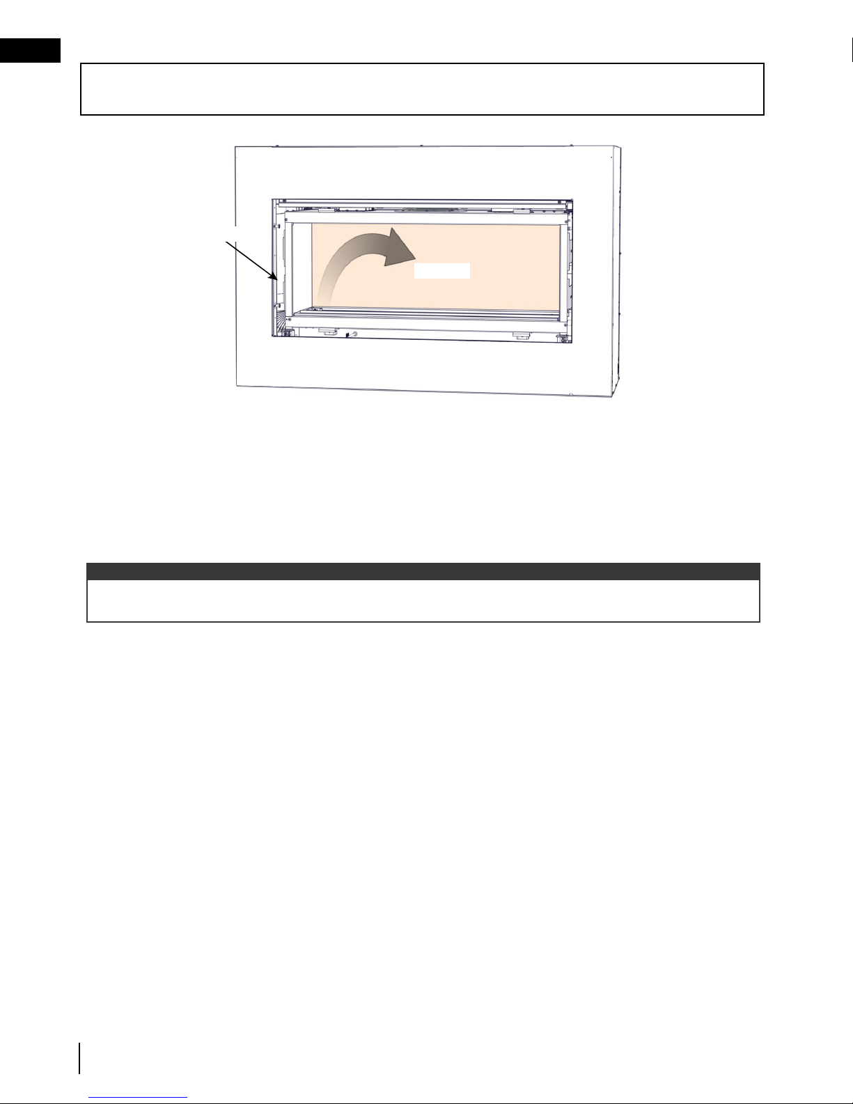
WARNING
!
If fitted with Dynamic Heat Control™
(DHC), DO NOT COVER OR PLACE
ITEMS AT AIR OUTLET OPENINGS!*
FIRE HAZARD!
The air that comes out of the DHC air
outlet is very hot. NEVER PLACE OR
ALLOW ITEMS TO FALL INSIDE THE
DHC OUTLET AIR OPENING.
*The DHC air outlet is shown at the front
note:
Dynamic Heat Control™ is optional on the Vector series (LV models) and included on the Luxuria series (LVX
models). Dynamic Heat Control™ is not available for L models. [PATENT PENDING]
of the fireplace enclosure (see
illustration), however it may be located at
ceiling height, it may be in the room
behind or in both rooms.
W415-1713 / 06.30.17
3
Page 4

EN
welcome
congratulations
Napoleon is proudly committed to your total home comfort. We are proud to say that our products continunously
surpass industry standards and our inspiration is you! More than anything, we want you to feel confident in
choosing Napoleon for your home. Our products are designed to provide that confidence and ensure that every
Napoleon product is beyond compare.
Napoleon products are designed with superior components and materials assembled by trained craftsmen who
take great pride in their work.
A barrier designed to reduce the risk of burns from the hot viewing glass is provided with the appliance for your
safety. This barrier must be installed.
Your Napoleon fireplace has been thoroughly inspected by a qualified technician before packaging to ensure that
you, the customer, receives the quality product that you expect from Napoleon.
Dealer : Fill in your dealer information (or business card) and the appliance installation information below.
Dealer Information
Name of Dealer:
Dealer Location:
Dealer Phone:
Dealer E-mail:
Customer:
Customer Address:
Date of Installation:
Location of the appliance:
Installer:
Serial Number:
Model:
Natural Gas:
Acies
L38N
L50N
Vector
LV38N-1
LV50N-2
LV62N
LV74N
Luxuria
LVX38N
LVX50N
LVX62N
LVX74N
Vector or
Luxuria
Dynamic Heat Control installed (Optional for LV / included for LVX)*
Dealer: Business card location
Propane:
L38N2
L50N2
LV38N2-1
LV50N2-2
LV62N2
LV74N2
LVX38N2
LVX50N2
LVX62N2
LVX74N2
L38P
L50P
LV38P-1
LV50P-2
LV62P
LV74P
LVX38P
LVX50P
LVX62P
*Dynamic Heat Control™ not available for L models.
L38P2
L50P2
LV38P2-1
LV50P2-2
LV62P2
LV74P2
LVX38P2
LVX50P2
LVX62P2
4
W415-1713 / 06.30.17
Page 5

table of contents
congratulations 4
1.0 getting to know your appliance 6
1.1 control access 7
1.2 rating plate / lighting instructions location 8
2.0 operating your appliance 9
2.1 using your appliance (L models only) 9
2.2 using your appliance (LV / LVX models only) 9
2.3 on/off components 9
2.3.1 changing the batteries in the battery holder (L models only) 10
2.3.2 turndown (L models only) 10
2.3.3 changing the batteries in the remote / battery holder (including switch) 11
3.0 remote control layout 12
4.0 remote control operation (optional for L models) 13
4.1 remote control operation 13
4.2 temperature display 13
4.3 flame height time 13
4.4 child proof function 13
4.5 LEDs 13
4.6 night light dimmer control 13
4.7 continuous pilot / intermittent pilot (CPI / IPI) selection 14
4.8 low battery / manual bypass 14
4.9 in the event of a power failure 14
4.10 eFIRE Controller application (optional for L models) 14
4.11 LED on/off light control (LV / LVX only) 15
5.0 clearances around fireplace 16
5.1 Dynamic Heat Control™ (LV optional / LVX included) 17
6.0 maintenance 18
6.1 care of glass 19
6.2 care of plated parts 20
6.3 glass guard assembly (GGA) removal / installation (LVX models only) 21
6.3.1 removing your GGA (LVX only) 21
6.3.2 installing your GGA (LVX models only) 23
6.4 safety barrier removal (L / LV models only) 25
6.5 door trim removal 25
6.6 firebox glass door removal 26
6.7 anti-condensation switch 26
7.0 replacements 27
8.0 accessories 28
9.0 troubleshooting 30
9.1 frequently asked questions 31
10.0 warranty 32
11.0 service history 33
EN
The camera icon indicates video tutorials are available as additional reference, visit
http://mynapoleon.napoleonproducts.com/download/index/44/1
W415-1713 / 06.30.17
5
Page 6

EN
1.0 getting to know your appliance
appliance components
This owner’s manual is written for a complete series of linear fireplaces that have a range of different features and
specifications. Before reading this manual, be sure you know which model of fireplace that you have. This information will have been filled out by the installer on the proceeding page and on the rating plate that is permanently
attached to the fireplace (see “appliance overview” section).
This manual is for the:
• Acies Series (model number prefix “L”)
• Vector Series (model number prefix “LV”)
• Luxuria Series (model number prefix “LVX”)
If required, more detailed technical information is included in the fireplace installation manual.
The information throughout this manual is believed to be correct at the time of printing. Wolf Steel Ltd. reserves
the right to change or modify any information within this manual at any time without notice. Changes, other than
editorial are denoted by a vertical line in the margin.
Visit the Napoleon website for the most current version of your appliance’s manual.
Glass guard
assembly
(LVX only)
Safety barrier
(L / LV only)
Door trim
Firebox
glass door
Glass guard
mounting
brackets
(LVX only)
Valve / rating
plate / lighting
instructions /
battery holder (L
only) location
Heat rail
(LVX only)
Some features and components illustrated may vary depending on your model.
6
W415-1713 / 06.30.17
Control cover
BurnerPilot
Single-sided model illustrated.
Battery holder
(including switch)
(LV/LVX only)
Page 7

appliance overview
PRE-FINISHING
The term “access side” is used in this manual and refers to the open side of the fireplace where the firebox glass
door is located.
In the case of see-thru appliances, there are firebox glass doors on both sides of the appliance. One of these
doors is fixed and cannot be removed. The access side can be identified with the pilot location.
EN
pilot location
access side
fixed side
pilot location
1.1 control access
Access to the control can be done by removing the safety barrier (L / LV models) or glass guard (LVX models),
glass door, door trim and control cover (see “maintenance” section for instructions on how to remove these
components).
VALVE
CONTROL
MODULE
ELECTRICAL
BOX
PRE-FINISHING
ACCESS PANEL
W415-1713 / 06.30.17
7
Page 8

EN
SAMPLE
getting to know your appliance
1.2 rating plate / lighting instructions location
Both the rating plate and lighting instructions are attached to a chain located on the left side of the control area
near the valve (access side). Remove the safety barrier or glass guard and the control cover to gain access to the
control area, see “control access” section.
To replace, slide the instructions back into the control area and slide the glass front into its locked position.
WARNING:
KEEP BURNER AND CONTROL
COMPARTMENT CLEAN. SEE
INSTALLATION AND OPERATING
INSTRUCTIONS MANUAL.
APPLIANCE NEEDS FRESH
AIR FOR SAFE OPERATION
AND MUST BE INSTALLED
WITH ADEQUATE PROVISIONS
FOR COMBUSTION
AND VENTILATION AIR.
GARDEZ LE BRÛLEUR ET LE
COMPARTIMENT DES
CONTRÔLES PROPRES.
CONSULTEZ LE MANUEL
D’INFORMATION ET
D’INSTALLATION. PAR
MESURE DE SÉCURITÉ.
CET APPAREIL DOIT
ÊTRE ALIMENTÉE EN AIR
FRAIS ET AVEC SUFFISANT
D’AIR COMBURANTET
DE VENTILATION.
CERTIFIED TO CANADIAN AND AMERICAN NATIONAL STANDARDS: CSA 2.22-2016 AND ANSI Z21.50-2016 FOR VENTED DECORATIVE GAS FIREPLACES.
CERTIFIÉ SELON LES NORMES NATIONALES CANADIENNES ET AMÉRICAINES: CSA 2.22-2016 ET ANSI Z21.50-2016 POUR LES APPAREILS À GAZ VENTILÉS DÉCORATIFS.
DIRECT VENT, VENTED GAS FIREPLACES. APPROVED FOR BEDROOM, BATHROOM AND BED-SITTING
ROOM INSTALLATION. SUITABLE FOR MOBILE HOME INSTALLATION IF INSTALLED IN ACCORDANCE
WITH THE CURRENT STANDARD CAN/CSA Z240MH SERIES GAS EQUIPPED MOBILE HOMES,
IN CANADA OR IN THE UNITED STATES THE MANUFACTURED HOME CONSTRUCTION AND
SAFETY STANDARD, TITLE 24 CFR, PART 3280. WHEN THIS US STANDARD IS NOT
APPLICABLE USE THE STANDARD FOR FIRE SAFETY CRITERIA FOR MANUFACTURED HOME
INSTALLATIONS, SITES AND COMMUNITIES, ANSI / NFPA 501A. THIS APPLIANCE MUST BE
INSTALLED IN ACCORDANCE WITH LOCAL CODES, IF ANY; IF NONE, FOLLOW THE CURRENT
ANSI Z223.1, OR CSA B149, INSTALLATION CODES.
FOLLOW THE INSTALLATION INSTRUCTIONS LOCATED IN THE INSTALLATION MANUAL.
MANIFOLD PRESSURE: 3.5 INCHES W.C. (NG)
PRESSION AU COLLECTEUR: 3.5" D'UNE
COLONNE D'EAU(GN)
9700539 (WSL) 4001657 (NGZ)
MIN SUPPLY PRESSURE: 4.5" W.C.(NG)
4001658 (NAC) 4001659 (WUSA)
PRESSION D'ALIMENTATION MIN: 4.5" D'UNE
LVX38N CLVX38N MODEL CLVX38P LVX38P
COLONNE D'EAU (GN)
MAX. SUPPLY PRESSURE: 7"* W.C. (NG)
PRESSION D'ALIMENTATION MAX: 7"* D'UNE
COLONNE D'EAU (GN)
*MAXIMUM INLET PRESSURE NOT TO EXCEED 13".
*PRESSION D'ALIMENTATION MAXIMALE NE DEVAIT PAS DÉPASSER 13".
NOT FOR USE WITH SOLID FUEL. FOR USE WITH GLASS
DOORS CERTIFIED WITH THIS APPLIANCE ONLY.
WARNING:DO NOT ADD ANY MATERIAL TO THE APPLIANCE, WHICH WILL COME IN CONTACT WITH THE FLAMES, OTHER
THAN THAT SUPPLIED BY THE MANUFACTURER WITH THE APPLIANCE.
MINIMUM CLEARANCE TO COMBUSTIBLE MATERIALS / DÉGAGEMENTS MINIMAUX DES MATÉRIAUX COMBUSTIBLES:
TOP, SIDES & BACK: PER STAND OFF SPACERS FOR FRAMING AND FINISHING MATERIALS. FOR FINISHING MATERIALS
SEE INSTALLATION MANUAL. DESSUS, CÔTÉS & ARRIÈRE: SELON LES ESPACEURS DE DÉGAGEMENT POUR LES MATÉRIAUX
D'OSSATURE SELON LA MANUEL DE PROPRIÉTAIRE POUR LES MATÉRIAUX DE FINITION.
TOP/ DESSUS 0" RECESSED DEPTH ONE SIDED/ PROFONDEUR D'ENCASTRE UNE FACE 17 15/16"
FLOOR / PLANCHER 0" RECESSED DEPTH SEE THRU/ PROFONDEUR D'ENCASTRE TRAVERS 16 3/16"
SIDES / CÔTÉS 0" BACK / ARRIÈRE 0"
VENT TOP / DESSUS DU CONDUIT D’ÉVENT 3"
VENT SIDES & BOTTOM / CÔTÉS ET DESSOUS DU CONDUIT D'ÉVENT 2"
VERTICAL VENT / CONDUIT D’ÉVENT VERTICAL 1"
MANTEL / TABLETTE 0" *
TOP, SIDES & BACK: PER STAND OFF SPACERS FOR FRAMING MATERIALS. FOR FINISHING MATERIALS
SEE INSTALLATION MANUAL. DESSUS, CÔTÉS & ARRIÈRE: SELON LES ESPACEURS DE DÉGAGEMENT POUR LES MATÉRIAUX
D'OSSATURE SELON LA MANUEL DE PROPRIÉTAIRE POUR LES MATÉRIAUX DE FINITION.
* MAXIMUM HORIZONTAL EXTENSION / L'EXTENSION HORIZONTALE MAXIMALE: 2". SEE INSTALLATION MANUAL FOR
GREATER EXTENSIONS. RÉFÉRER AU MANUEL D'INSTRUCTION POUR DES EXTENSIONS PLUS GRANDES.
SEE INSTALLATION MANUAL FOR MINIMUM AND MAXIMUM VENT LENGTHS. RÉFÉRER AU MANUEL D'INSTALLATION
DE PROPRIÉTAIRE POUR LES LONGUEURS D'ÉVACUATION MINIMALE ET MAXIMALE.
WOLF STEEL LTD.
IMPROPER INSTALLATION,
ADJUSTMENT, ALTERATION,
SERVICE OR MAINTENANCE
CAN CAUSE PROPERTY DAMAGE,
PERSONAL INJURY OR LOSS OF
LIFE. REFER TO OWNER’S
MANUAL. INSTALLATION AND
SERVICE MUST BE PERFORMED
BY A QUALIFIED INSTALLER,
SERVICE AGENCY OR THE
GAS SUPPLIER.
ATTENTION:
UN INSTALLATION OU UNE
MODIFICATION INAPPROPRIÉE
DU RÉGLAGE, DU SERVICE ET DE
L’ENTRETIEN POURRAIENT ÊTRE
LA CAUSE DE DOMMAGES À LA
PROPRIETÉ DE BLESSURES
CORPORELLES OU MÊME LA
MORT. CONSULTER LE MANUEL
D’INFORMATION, L’INSTALLATION
ET LE SERVICE DOIVENT
ÊTRE EXECUTÉS PAR UN
INSTALLATEUR QUALIFIÉ POUR
LE GAZ, UNE ENTREPRISE DE
SERVICE OU LE FOURNISSEUR
DE GAZ SEULEMENT.
FOR USE WITH SAFETY BARRIER W010-4186.
0-4500FT (0-1370m) ALTITUDE / ÉLÉVATION 0-4500FT (0-1370m)
32,000 BTU/h INPUT / ALIMENTATION 32,000 BTU/h
REDUCED INPUT / ALIMENTATION RÉDUITE
22,000 BTU/h
24 NAPOLEON ROAD, BARRIE, ON, L4M 0G8 CANADA
CAUTION:
HOT WHILE OPERATING. DO NOT TOUCH.
KEEP CHILDREN, CLOTHING, FURNITURE,
GASOLINE OR OTHER FLAMMABLE VAPORS
AWAY.
AVERTISSEMENT:
L’APPAREIL EST CHAUD PENDANT SON
FONCTIONNEMENT. LES ENFANTS, LES
VÉTEMENTS, LES MEUBLES, L’ESSENCE ET
AUTRES LIQUIDES QUI ÉMETTENT DES GAZ
VOLATILS INFLAMMABLES DOIVENT
ÉTRE TENUS ÉLOIGNES DE L’APPAREIL.
“This appliance is only for use with the type(s)
of gas indicated on the rating plate and may
be installed in an aftermarket, permanently
located, manufactured home (USA only) or
mobile home, where not prohibited by local
codes. See owner’s manual for details. This
appliance is supplied with a conversion kit.”
«Cet appareil doit être utilisé uniquement
avec les types de gaz indiqués sur la plaque
signalétique et peut être installé dans une
maison préfabriquée (É.-U. seulement) ou
mobile installée à demeure si les règlements
locaux le permettent. Voir la notice de
l’utilisateur pour plus de renseignements. Une
trousse de conversion est fournie avec cet
appareil.»
FOYER À GAZ VENTILÉ. HOMOLOGUÉ POUR INSTALLATION DANS UNE CHAMBRE À COUCHER, UNE
SALLE DE BAIN ET UN STUDIO. APPROPRIÉ POUR INSTALLATION DANS UNE MAISON MOBILE SI
SON INSTALLATION CONFORME AUX EXIGENCES DE LA NORME CAN/CSA Z240MH SÉRIE DE
MAISONS MOBILES ÉQUIPÉES AU GAZ, EN VIGUEUR AU CANADA OU AUX ÉTATS-UNIS DE LA
NORME DE SÉCURITÉ ET DE CONSTRUCTION DE MAISONS MANUFACTURÉES, TITRE 24
CFR, SECTION 3280. DANS LE CAS OU CETTE NORME D'ÉTATS-UNIS NE PEUT ÊTRE
APPLIQUÉE, SE RÉFÉRER A LA NORME RELATIVE AU CRITÈRE DE MESURES DE SÉCURITÉ
CONTRE L'INCENDIE POUR LES INSTALLATIONS DANS LES MAISONS MANUFACTURÉS, LES
SITES ET LES COMMUNAUTÉS, ANSI/NFPA 501A. CODES. INSTALLER L’APPAREIL SELON LES
CODES OU RÈGLEMENTS LOCAUX, OU EN L’ABSENCE DE TELS RÈGLEMENTS, SELON LES
CODES D’INSTALLATION ANSI Z223.1 OU CSA-B149 EN VIGUER.
BARRIÈRE W010-4186. SUIVEZ LES INSTRUCTIONS D'INSTALLATION QUI SE TROUVENT DANS LE
25,000 BTU/h
P4
40.2%40.2%
UN COMBUSTIBLE SOLIDE NE DOIT PAS ÊTRE UTILISÉ AVEC
CET APPAREIL. UTILISER AVEC LES PORTES VITRÉES
HOMOLOGUÉES SEULEMENT AVEC CETTE APPAREIL.
AVERTISSEMENT: N’AJOUTEZ PAS A CET APPAREIL AUCUN MATÉRIAU DEVANT ENTRER EN CONTACT AVEC
LES FLAMMES AUTRE QUE CELUI QUI EST FOURNI AVEC CET APPAREIL PAR LE FABRICANT.
THE APPLIANCE MUST BE VENTED USING THE APPROPRIATE NAPOLEON VENT KITS. SEE OWNER'S INSTALLATION MANUAL
FOR VENTING SPECIFICS. PROPER REINSTALLATION AND RESEALING IS NECESSARY AFTER SERVICING THE VENT-AIR
INTAKE SYSTEM.
L'APPAREIL DOIT ÉVACUER SES GAZ EN UTILISANT L'ENSEMBLE D'ÉVACUATION PROPRE À NAPOLEON. RÉFÉRER AU
MANUEL D'INSTALLATION DE PROPRIÉTAIRE POUR L'ÉVACUATION PRÉCISE. IL EST IMPORTANT DE BIEN RÉINSTALLER ET
RESCELLER L'ÉVENT APRÈS AVOIR ASSURÉ LE MAINTIEN DU SYSTÈME DE PRISE D'AIR.
ELECTRICAL RATING: 115V, 60HZ. LESS THAN 12 AMPERES
SPÉCIFICATIONS ÉLECTRIQUES: 115V, 60HZ. MOINS DE 12 AMPÈRE
DECORATIVE PRODUCT: NOT FOR USE AS A HEATING APPLIANCE
PRODUIT DÉCORATIF: NE PAS UTILISER COMME APPAREIL DE CHAUFFAGE
SERIAL NUMBER/NO. DE SÉRIE: LVX38
FOR YOUR SAFETY:
DO NOT STORE OR USE GASOLINE
OR OTHER FLAMMABLE VAPORS
AND LIQUIDS IN VICINITY OF THIS
OR ANY OTHER APPLIANCE.
CAUTION: DO NOT OPERATE
THE FIREPLACE WITH THE GLASS
REMOVED, CRACKED OR BROKEN.
REPLACEMENT OF THE GLASS
SHOULD BE DONE BY A LICENSED
OR QUALIFIED PERSON.
POUR VOTRE
SÉCURITÉ:
NE PAS ENTREPOSER NI UTILISER
D’ESSENCE NI D’AUTRES VAPEURS
OU LIQUIDES INFLAMMABLES
DANS LE VOISINAGE DE CET
APPAREIL OU DE TOUT AUTRE
APPAREIL.
AVERTISSEMENT: NE PAS
UTILISER L’APPAREIL SI LE
PANNEAU FRONTAL EN VERRE
N’EST PAS EN PLACE, EST CRAQUÉ
OU BRISÉ. CONFIEZ LE
REMPLACEMENT DU
PANNEAU À UN
TECHNICIEN
AGRÉÉ.
POUR UTILISATION AVEC
MANUEL D'INSTALLATION.
MANIFOLD PRESSURE: 10 INCHES W.C.(P)
PRESSION AU COLLECTEUR: 10" D'UNE
COLONNE D'EAU (P)
MIN SUPPLY PRESSURE: 11" W.C. (P)
PRESSION D'ALIMENTATION MIN: 11" D'UNE
COLONNE D'EAU (P)
MAX. SUPPLY PRESSURE: 13" W.C. (P)
PRESSION D'ALIMENTATION MAX: 13" D'UNE
COLONNE D'EAU (P)
W385-2185
Pilot location
N'AJOUTEZ PAS A
UN COMBUSTIBLE SOLIDE NE
DOIT PAS ÊTRÉ UTILISÉ AVEC
CET APPAREIL. UTILISER AVEC
LES PORTES VITRÉES
HOMOLOGUÉES SEULEMENT
AVEC CETTE UNITÉ.
AVERTISSEMENT:
CET APPAREIL AUCUN MATÉRIAU DEVANT
ENTRER EN CONTACT AVEC LES FLAMMES
AUTRE QUE CELUI QUI EST FOURNI AVEC
CET APPAREIL PAR LE FABRICANT.
DÉGAGEMENTS MINIMAUX DES
MATÉRIAUX COMBUSTIBLES:
DESSUS 0”
PROFONDEUR D'ENCASTRÉ 25"
PLANCHER 0”
ÉVENT 2"
CÔTES 0”
MANTEAU 15" *
ARRIÉRE 0”
MODEL PROPANE
LHD50PT
0-4500FT (0-1370M)
30,000 BTU/H
23,000 BTU/H
#53
10" WATER COLUMN/D'UNE COLONNE D'EAU
11" WATER COLUMN/D'UNE COLONNE D'EAU
13" WATER COLUMN/ D'UNE COLONNE D'EAU
L'APPAREIL DOIT ÉVACUER SES GAZ EN UTILISANT L'ENSEMBLE
D'ÉVACUATION PROPRE A NAPOLEON. RÉFÉRER AU MANUEL
ALTITUDE / ÉLÉVATION
D'INSTALLATION DE PROPRIÉTAIRE POUR L'ÉVACUATION
INPUT / ALIMENTATION
PRÉCISE. IL EST IMPORTANT DE BIEN RÉINSTALLER ET
ORIFICE / INJECTEUR
RESCELLER L'ÉVENT APRÈS AVOIR ASSURÉ LE MAINTIEN DU
SYSTÉME DE PRISE D'AIR.
MANIFOLD PRESSURE /
DESSUS, COTÉS & ARRIÈRE: SELON LES ESPACEURS DE DÉGAGEMENT POUR LES MATÉRIAUX D'OSSATURE
SELON LE MANUEL DE PROPRIÉTAIRE POUR LES MATÉRIAUX DE FINITION.
* L'EXTENSION HORIZONTALE MAXIMALE: 2". RÉFÉRER AU MANUEL D'INSTRUCTION POUR DES EXTENSIONS
PRESSION AU COLLECTEUR
PLUS GRANDES. RÉFÉRER AU MANUEL D'INSTALLATION DE PROPRIÉTAIRE.
REDUCED INPUT / ALIMENTATION RÉDUITE
MINIMUM SUPPLY PRESSURE /
MAXIMUM SUPPLY PRESSURE /
#38
PRESSION D'ALIMENTATION MINIMALE
PRESSION D'ALIMENTATION MAXIMALE
30,000 BTU/H
INTAKE SYSTEM.
23,000 BTU/H
0-4500FT (0-1370M)
LHD50NT
GAZ NATURAL
MODEL NATURAL GAS /
VENTED GAS FIREPLACE HEATER. APPROVED FOR BEDROOM, BATHROOM AND BED-SITTING ROOM INSTALLATION. SUITABLE FOR MOBILE HOME INSTALLATION IF INSTALLED IN ACCORDANCE WITH THE
CURRENT STANDARD CAN/CSA Z240MH SERIES GAS EQUIPPED MOBILE HOMES, IN CANADA OR IN THE UNITED STATES THE MANUFACTURED HOME CONSTRUCTION AND SAFETY STANDARD, TITLE 24 CFR,
CERTIFIED UNDER / HOMOLOGUE SELON LES NORMES: CSA 2.33b - 2008, ANSI Z21.88b- 2008 VENTED GAS FIREPLACE HEATER / APPAREIL DE CHAUFFAGE ALIMENTÉ
3.5" WATER COLUMN/D'UNE COLONNE D'EAU
PART 3280. WHEN THIS US STANDARD IS NOT APPLICABLE USE THE STANDARD FOR FIRE SAFETY CRITERIA FOR MANUFACTURED HOME INSTALLATIONS, SITES AND COMMUNITIES, ANSI / NFPA 501A.
AU GAZ ET VENTILÉ
FOYER DE CHAUFFAGE AU GAZ AVEC ÉVACUATION. HOMOLOGUÉ POUR INSTALLATION DANS UNE CHAMBRE À COUCHER, UNE SALLE DE BAIN ET UN STUDIO. APPROPRIÉ POUR INSTALLATION DANS UNE
MAISON MOBILE SI SON INSTALLATION CONFORME AUX EXIGENCES DE LA NORME CAN/CSA Z240MH SÉRIE DE MAISONS MOBILES ÉQUIPÉES AU GAZ, EN VIGUEUR AU CANADA OU AUX ÉTATS-UNIS DE LA
4.5" WATER COLUMN/D'UNE COLONNE D'EAU
NORME DE SECURITÉ ET DE CONSTRUCTION DE MAISONS MANUFACTURÉES, TITRE 24 CFR, SECTION 3280. DANS LE CAS OU CETTE NORME D'ÉTATS-UNIS NE PEUT ÊTRE APPLIQUÉE, SE RÉFÉRER A LA NORME
FOR VENTING SPECIFICS. PROPER REINSTALLATION AND
RELATIVE AU CRITÈRE DE MESURES DE SÉCURITÉ CONTRE L'INCENDIE POUR LES INSTALLATIONS DANS LES MAISONS MANUFACTURÉS, LES SITES ET LES COMMUNAUTÉS, ANSI/NFPA 501A.
7.0" WATER COLUMN/D'UNE COLONNE D'EAU
THE APPLIANCE MUST BE VENTED USING THE APPROPRIATE
NAPOLEON VENT KITS. SEE OWNERS INSTALLATION MANUAL
RESEALING IS NECESSARY AFTER SERVICING THE VENT-AIR
W/N 16131
REFERENCE #
DO NOT ADD ANY MATERIAL
:
NOT FOR USE WITH
SOLID FUEL. FOR USE
WITH GLASS DOORS
CERTIFIED WITH THIS
UNIT ONLY.
WARNING
TO THE APPLIANCE, WHICH WILL COME
IN CONTACT WITH THE FLAMES, OTHER
THAN THAT SUPPLIED BY THE
MANUFACTURER WITH THE APPLIANCE.
MINIMUM CLEARANCE TO
COMBUSTIBLE MATERIALS:
TOP 0”
FLOOR 0”
RECESSED DEPTH ONE SIDED 23"
RECESSED DEPTH SEE THRU 13.5”
FRAMING (NOT INCLUDING
FACE MATERIAL)
ELECTRICAL RATING: 115V 0.82AMP, 60HZ
SIDES 0”
VENT 2"
BACK 0”
MANTLE 15" *
TOP, SIDES & BACK: PER STAND OFF SPACERS FOR FRAMING MATERIALS. FOR FINISHING MATERIALS
SEE OWNERS MANUAL
* MAXIMUM HORIZONTAL EXTENSION / L'EXTENSION
HORIZONTALE MAXIMALE: 2". SEE INSTRUCTION MANUAL FOR GREATER EXTENSIONS.
SEE OWNER'S INSTRUCTION MANUAL FOR MINIMUM AND MAXIMUM VENT LENGTHS.
W385-2007
CLASSIFICATION: 115V 0.82AMP, 60HZ
Valve location
SERIAL NUMBER/NO. DE SÉRIE: LV50
MADE IN CANADA / FABRIQUÉ AU CANADA
WOLF STEEL LTD. BARRIE, ONTARIO, CANADA
This illustration is for reference only. Refer to the rating plate on the appliance for accurate information.
note:
The rating plate must remain with the appliance at all times. It must not be removed.
8
W415-1713 / 06.30.17
Page 9
2.0 operating your appliance
When operating your appliance for the first time, there is a required burn-in process that cures materials used
to manufacture the fireplace that may emit both vapors and an odor. These are normal when operating a new
appliance for the first time. Ensure adequate air circulation is provided during burn-in process, if this was not
completed by the installer during installation.
operating your appliance
2.1 using your appliance (L models only)
To turn the appliance on:
A Turn the on/off switch on.
B After 3-5 seconds, the control will start a spark at the pilot, light the pilot and then the burner. The spark
period will last 60 seconds, or until the pilot has lit.
C When used for the first time, if the burn-in process was not completed by the installer; run appliance
continuously for 4 hours (burn-in).
D Turn the appliance off. Wait until appliance is completely cool before moving to the next step.
E Remove the safety barrier and firebox glass door. Clean firebox glass door (see “maintenance” section).
Replace firebox glass door and safety barrier.
For more detailed information, see your installation manual or contact your authorized dealer.
2.2 using your appliance (LV / LVX models only)
To turn the appliance on:
A For battery holder (including switch) operation: Turn the appliance on/off by turning the battery holder
(including switch) to the ‘on’ and/or ‘off’ position.
For remote control operation: Ensure the battery holder (including switch) is in the ‘remote’ position. Press
and release the on/off button on the remote control. An audible beep should be heard from the remote.
B After 3-5 seconds, the control will start a spark at the pilot, light the pilot and then the burner. The spark
period will last 60 seconds, or until the pilot has lit.
C When used for the first time, if the burn-in process was not completed by the installer; run appliance
continuously for 4 hours.
D Turn the appliance off. Wait until appliance is completey cool before moving to the next step.
E Remove glass guard (LVX models) or safety barrier (LV models) and firebox glass door. Clean firebox glass
door (see “maintenance” section). Replace firebox glass door and glass guard/safety barrier.
EN
For more detailed information, see your installation manual or contact your authorized dealer.
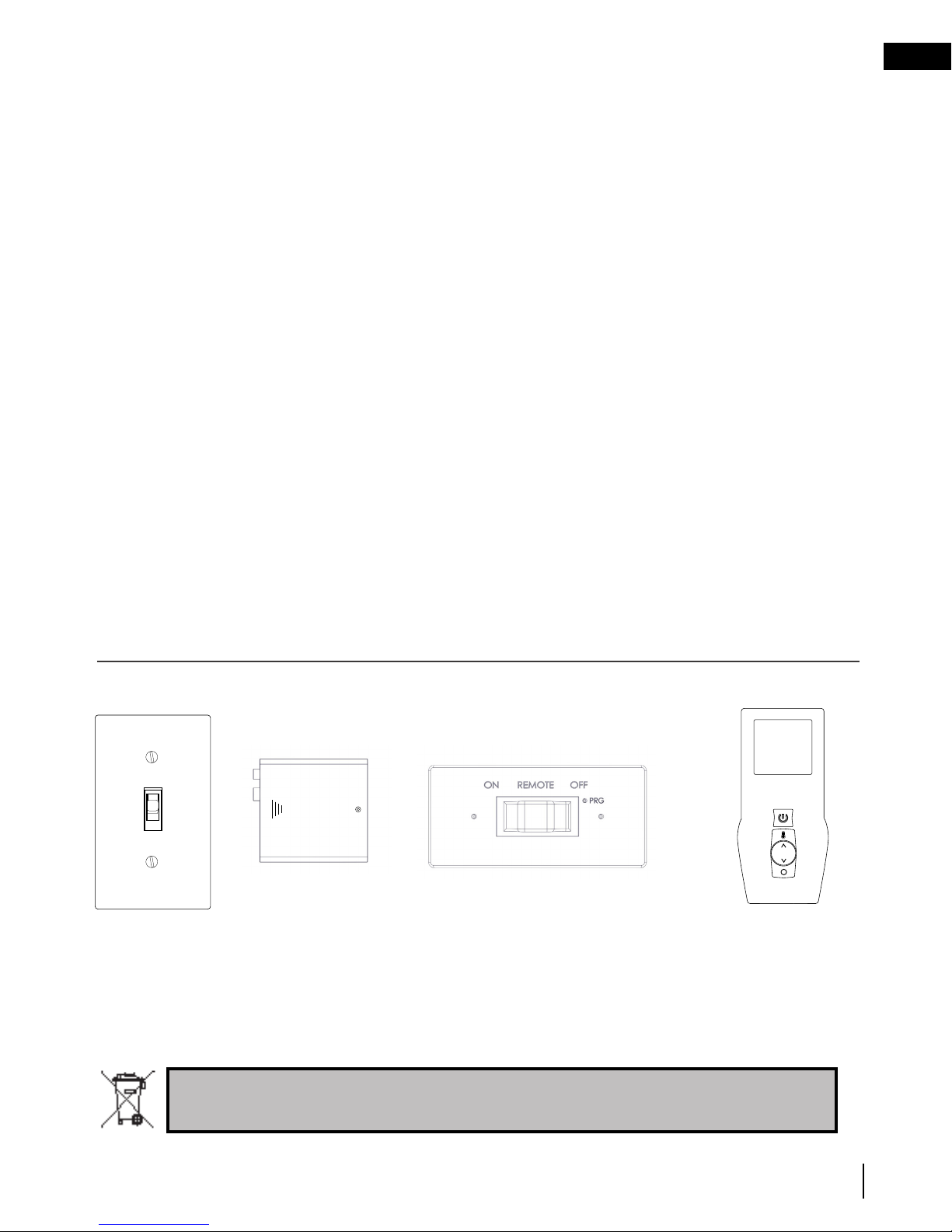
2.3 on/off components
| On/off switch | Battery holder | Battery holder (including switch) | Remote control |
(Not supplied)
(Optional for LV / LVX
models)
(L only)
(Optional for L models)
(Optional for L models)
Batteries must be disposed of according to the local laws and regulations. Some batteries may be
recycled, and may be accepted for disposal at your local recycling center. Check with your
municipality for recycling instructions.
W415-1713 / 06.30.17
9
Page 10
EN
operating your appliance
2.3.1 changing the batteries in the battery holder (L models only)
WARNING
!
• Ensure the gas and electrical power to the appliance is turned off.
• Appliance may be hot, do not service until the appliance has cooled.
note:
In the event of a power failure, your appliance can be operated using the supplied battery back-up. If a power
failure occured, remove the batteries from the holder once the power has been restored. The system will drain
the batteries if they are left in the battery holder.
A. Turn off the gas and disconnect the electrical power supply from the appliance.
B. Remove the safety barrier, control cover and door trim to easily access the control compartment (see
“maintenance” section for instructions on how to remove these components.
C. Locate the battery housing located near the control board (see illustration below).
D. Open the battery housing by sliding the back piece upwards and off of the battery housing. Remove the
four “AA” alkaline batteries and install four new “AA” alkaline batteries into the battery housing. Ensure the
positive and negative ends correspond with those identified on the holder.
E. Place the battery housing back into the control compartment, ensure that the battery housing is placed in
a clean and easily accessible location.
F. Reinstall the safety barrier. The safety barrier must be installed at all times during the appliance operation.
G. Turn the gas and electrical power back on to begin operating the appliance.
Red wire
Black wire
Control module
Battery housing
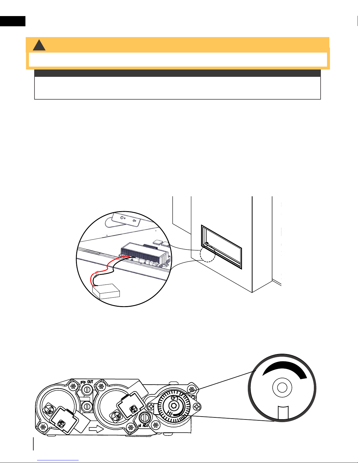
2.3.2 turndown (L models only)
Manual adjustments to your fireplace must only be made when the appliance is off and complete cool.
Allow safety barrier to cool before making adjustment.
The Acies Series is equipped with a manual gas control knob (located on the valve) that adjusts the flame height to
suit your preference. To access the gas control knob, remove your safety barrier, control cover and door trim (see
“maintenance” section for instructions on how to remove these components.
Use only your hand to turn the gas control knob (never use tools). If the knob will
not turn by hand, do not try to repair it. Contact a qualified technician.
O
L
Flame adjustment
H
I
10
W415-1713 / 06.30.17
Page 11

operating your appliance
(4) AA Batteries
ON REMOTE OFF
2.3.3 changing the batteries in the remote / battery holder (including switch)
WARNING
!
• Ensure the gas and electrical power to the appliance is turned off.
• Appliance may be hot, do not service until the appliance has cooled.
Battery holder (including
switch) would have been
located close to the
appliance during installation
EN
(4) AA Batteries
ON REMOTE OFF
(Illustrated with cover
plate removed)
For battery holder (including switch):
A. Remove the two screws securing cover plate to battery holder (including switch). Do not discard.
B. Remove the 4 “AA” alkaline batteries in the battery holder (including switch) and replace with new ones.
Note the polarity of the batteries and insert as indicated on the cover (+/-).
C. Secure the cover plate to the battery holder (including switch) using the screws removed in step A.
For remote control:
A. Press the securing clip on the back of the remote control to release the back cover. Remove the 3 “AAA”
alkaline batteries in the remote and replace with new batteries then press the ON button. The battery
holder will beep 4 times to indicate that the remote’s command is accepted.
Battery Holder
(including switch)
(4) AA Batteries
Remote control
Slider Switch
Reset / Program
Button (PRG)
W415-1713 / 06.30.17
11
Page 12

EN
3.0 remote control layout
transmitter layout
note:
The remote control is optional for the L series.
Transmission
Flame ON
Hot Air Distribution*
Blower
Key Lock
Low battery alarm
Room
Temperature
CPI mode
LED Lights
LED Light
Accent Lights
*Where fitted and where connected to the appliance control board.
Remote Control
Power
(ON/OFF)
Function
Adjustment
(Flame Height, Hot Air
Distribution Speed, and
LED Light Colour Change)
Cycle Through Functions
(Flame, Hot Air
Distribution, and Light
Functions)
note:
Install the 3 ‘AAA’
batteries into the
remote control, as
shown, then press
the ON button. The
battery holder will
beep 4 times to
indicate that the
remote’s command is
accepted.
12
W415-1713 / 06.30.17
Page 13

A. Press the on / off key on the transmitter. The transmitter display will
show all active icons on the screen. A single “beep” from the receiver will
confi rm reception of the command.
Blue LCD Display
On / Off Key
Up / Down Arrow Key
Mode Key
Temperature Key
76
°F
OFF
76
°F
ON
°F
ADD TITLE: TEMPERATURE DISPLAY
A. With the system in the off position, press the temperature key
and the mode key at the same time to change from degrees F to
C.
B. Look at the LCD screen on the transmitter to verify that a C or F is
visible to the right of the room temperature display.
ADD TITLE: HAND HELD REMOTE OPERATION
The remote control has six (6) fl ame levels. With the system on and the fl ame level at the maximum, press the
down arrow key once and it will reduce the fl ame height by one step until the fl ame is turned off.
The up arrow key will increase the fl ame height each time it is pressed. If the up arrow key is pressed while
the system is on but the fl ame is off, the fl ame will come on at the high position. A single “beep” will confi rm
reception of the command.
ADD TITLE: FLAME HEIGHT
Blue LCD Display
On / Off Key
Up / Down Arrow Key
Mode Key
Temperature Key
73 23
76
°F
68
Room Temperature
Set Temperature
76
°F
MAX
76
°F
OFF
76
°F
76
°F
76
°F
Hi
Flame Off Flame at level 1 Flame at level 5 Flame at “Hi” level 6
76
°F
OFF
76
°F
ON
76
°F
76
°F
68
76
°F
Hi
76
°F
OFF
76
°F
ON
SMART
°F °C
If the appliance is equipped with a hot air circulating fan, the speed of
the fan can be controlled by the remote system. The fan speed can be
adjusted through six (6) speeds.
A. Use the mode key to guide you to the fan control icon.
B. Use the up/down arrow keys to turn on/off or adjust the fan
speed. A single “beep” will confi rm reception of the command.
ADD TITLE: FAN SPEED
76
°F
OFF
76
°F
ON
76
°F
76
°F
68
76
°F
Hi
ADD TITLE: CHILD PROOF FUNCTION
Blue LCD Display
On / Off Key
Up / Down Arrow Key
Mode Key
Temperature Key
73 23
76
°F
68
Room Temperature
76
°F
MAX
76
°F
OFF
76
°F
76
°F
76
°F
Hi
Flame Off Flame at level 1 Flame at level 5 Flame at “Hi” level 6
76
°F
OFF
76
°F
ON
76
°F
76
°F
68
76
°F
Hi
76
°F
OFF
76
°F
76
°F
IPI
76
°F
CPI
ON
SMART
°F °C
Blue LCD Display
On / Off Key
Up / Down Arrow Key
Mode Key
Temperature Key
73 23
76
°F
68
Room Temperature
76
°F
MAX
76
°F
OFF
76
°F
76
°F
76
°F
Hi
Flame Off Flame at level 1 Flame at level 5 Flame at “Hi” level 6
76
°F
76
°F
OFF
76
°F
ON
76
°F
76
°F
68
76
°F
Hi
76
°F
OFF
76
°F
76
°F
IPI
76
°F
CPI
ON
SMART
°F °C
Blue LCD Display
On / Off Key
Up / Down Arrow Key
Mode Key
Temperature Key
73 23
76
°F
OFF
76
°F
ON
76
°F
°F °C
Blue LCD Display
On / Off Key
Up / Down Arrow Key
Mode Key
Temperature Key
73 23
76
°F
OFF
76
°F
ON
76
°F
°F
°F
°F °C
When the desired blower speed is selected, the blower will automatically come on 5 minutes after the main
burner has been turned on and remain on twelve minutes after it has been turned off.
note:
76
°F
OFF
76
°F
ON
76
°F
°F
°F
76
°F
OFF
76
°F
ON
76
°F
76
°F
68
76
°F
Hi
76
°F
76
°F
Blue LCD Display
On / Off Key
Up / Down Arrow Key
Mode Key
Temperature Key
76
°F
OFF
76
°F
ON
°F
Blue LCD Display
On / Off Key
Up / Down Arrow Key
Mode Key
Temperature Key
73 23
76
°F
68
Room Temperature
Set Temperature
76
°F
MAX
76
°F
OFF
76
°F
ON
76
°F
76
°F
68
76
°F
Hi
76
°F
OFF
76
°F
ON
SMART
°F °C
76
°F
OFF
76
°F
ON
76
°F
Blue LCD Display
On / Off Key
Up / Down Arrow Key
Mode Key
Temperature Key
73 23
76
°F
68
Room Temperature
76
°F
76
°F
OFF
76
°F
ON
76
°F
76
°F
68
76
°F
Hi
76
°F
OFF
76
°F
ON
SMART
°F °C
Blue LCD Display
On / Off Key
Up / Down Arrow Key
Mode Key
Temperature Key
73 23
76
°F
68
Room Temperature
76
°F
76
°F
OFF
76
°F
ON
76
°F
76
°F
68
76
°F
Hi
76
°F
OFF
76
°F
ON
SMART
°F °C
Blue LCD Display
On / Off Key
Up / Down Arrow Key
Mode Key
Temperature Key
76
°F
OFF
76
°F
ON
76
°F
Blue LCD Display
On / Off Key
Up / Down Arrow Key
Mode Key
Temperature Key
73 23
76
°F
OFF
76
°F
ON
76
°F
°F
°F
°F °C
confi rm reception of the command.
Blue LCD Display
On / Off Key
Up / Down Arrow Key
Mode Key
Temperature Key
76
°F
OFF
76
°F
ON
°F
ADD TITLE: TEMPERATURE DISPLAY
A. With the system in the off position, press the temperature key
and the mode key at the same time to change from degrees F to
C.
B. Look at the LCD screen on the transmitter to verify that a C or F is
visible to the right of the room temperature display.
The remote control has six (6) fl ame levels. With the system on and the fl ame level at the maximum, press the
down arrow key once and it will reduce the fl ame height by one step until the fl ame is turned off.
The up arrow key will increase the fl ame height each time it is pressed. If the up arrow key is pressed while
the system is on but the fl ame is off, the fl ame will come on at the high position. A single “beep” will confi rm
reception of the command.
ADD TITLE: FLAME HEIGHT
Blue LCD Display
On / Off Key
Up / Down Arrow Key
Mode Key
Temperature Key
73 23
76
°F
68
Room Temperature
Set Temperature
76
°F
MAX
76
°F
OFF
76
°F
76
°F
76
°F
Hi
Flame Off Flame at level 1 Flame at level 5 Flame at “Hi” level 6
76
°F
OFF
76
°F
ON
76
°F
76
°F
68
76
°F
Hi
76
°F
OFF
76
°F
ON
SMART
°F °C
If the appliance is equipped with a hot air circulating fan, the speed of
the fan can be controlled by the remote system. The fan speed can be
adjusted through six (6) speeds.
A. Use the mode key to guide you to the fan control icon.
B. Use the up/down arrow keys to turn on/off or adjust the fan
speed. A single “beep” will confi rm reception of the command.
ADD TITLE: FAN SPEED
76
°F
OFF
76
°F
ON
76
°F
76
°F
68
76
°F
Hi
ADD TITLE: CHILD PROOF FUNCTION
This function will lock the keys to avoid unsupervised operation.
A. Press the mode and up keys at the same time.
B. To de-activate this function, press the mode and up keys at the same time.
Blue LCD Display
On / Off Key
Up / Down Arrow Key
Mode Key
Temperature Key
73 23
76
°F
68
Room Temperature
76
°F
MAX
76
°F
OFF
76
°F
76
°F
76
°F
Hi
Flame Off Flame at level 1 Flame at level 5 Flame at “Hi” level 6
76
°F
76
°F
OFF
76
°F
ON
76
°F
76
°F
68
76
°F
Hi
76
°F
OFF
76
°F
76
°F
IPI
76
°F
CPI
ON
SMART
°F °C
Blue LCD Display
On / Off Key
Up / Down Arrow Key
Mode Key
Temperature Key
73 23
76
°F
68
Room Temperature
76
°F
MAX
76
°F
OFF
76
°F
76
°F
76
°F
Hi
Flame Off Flame at level 1 Flame at level 5 Flame at “Hi” level 6
76
°F
76
°F
OFF
76
°F
ON
76
°F
76
°F
68
76
°F
Hi
76
°F
OFF
76
°F
76
°F
IPI
76
°F
CPI
ON
SMART
°F °C
Blue LCD Display
On / Off Key
Up / Down Arrow Key
Mode Key
Temperature Key
73 23
76
°F
OFF
76
°F
ON
76
°F
°F °C
Blue LCD Display
On / Off Key
Up / Down Arrow Key
Mode Key
Temperature Key
73 23
76
°F
OFF
76
°F
ON
76
°F
°F
°F
°F °C
When the desired blower speed is selected, the blower will automatically come on 5 minutes after the main
burner has been turned on and remain on twelve minutes after it has been turned off.
note:
ADD TITLE: NIGHT LIGHT
The auxiliary function controls the AUX power outlet on the control module
which controls the Night Light™.
A. Use the mode key to guide you to the AUX icon.
B. Pressing the up arrow key will activate the Night Light™.
C. Pressing the down arrow key will turn the Night Light™ off. A single
“beep” will confi rm the reception of the command.
76
°F
OFF
76
°F
ON
76
°F
OFF
76
°F
ON
76
°F
76
°F
68
76
°F
Hi
will confi rm reception of the command.
76
°F
76
°F
Hi
76
°F
OFF
76
°F
ON
76
°F
76
°F
68
76
°F
Hi
76
°F
OFF
76
°F
4.0 remote control operation (optional for L models)
ADD TITLE: HAND HELD REMOTE OPERATION
4.1 remote control operation
A. Press the on / off key on the transmitter. The transmitter display will
show all active icons on the screen. A single “beep” from the receiver will
confi rm reception of the command.
ADD TITLE: TEMPERATURE DISPLAY
4.2 temperature display
A. With the system in the off position, press the temperature key
and the mode key at the same time to change from degrees F to
C.
B. Look at the LCD screen on the transmitter to verify that a C or F is
visible to the right of the room temperature display.
ADD TITLE: FLAME HEIGHT
4.3 flame height time
The remote control has six (6) fl ame levels. With the system on and the fl ame level at the maximum, press the
down arrow key once and it will reduce the fl ame height by one step until the fl ame is turned off.
The up arrow key will increase the fl ame height each time it is pressed. If the up arrow key is pressed while
the system is on but the fl ame is off, the fl ame will come on at the high position. A single “beep” will confi rm
reception of the command.
4.4 child proof function
4.5 LEDs
4.6 night light dimmer control
This function will lock the keys to avoid unsupervised operation.
A. Press the mode and up keys at the same time.
B. To de-activate this function, press the mode and up keys at the same time.
ADD TITLE: NIGHT LIGHT
The auxiliary function controls the AUX power outlet on the control module
which controls the Night Light™.
A. Use the mode key to guide you to the AUX icon.
B. Pressing the up arrow key will activate the Night Light™.
C. Pressing the down arrow key will turn the Night Light™ off. A single
ADD TITLE: Night Light Dimmer Control
The auxiliary function controls the Night Light™ with dimmable control.
A. Use the mode key to guide you to the Night Light™ icon.
B. The intensity of the output can be adjusted through 6 levels.
“beep” will confi rm the reception of the command.
Use the up/down arrow keys to adjust the output level. A single beep
LEDs.
OFF
76
Flame Off Flame at level 1 Flame at level 5 Flame at “Hi” level 6
°F
76
°F
LEDs.
LEDs off. A single
remote control operation
76
73 23
°F
°F °C
76
Hi
76
OFF
76
OFF
°F
76
°F
ON
°F
W415-1713 / 06.30.17
EN
°F
°F
76
°F
76
13
Page 14

Blue LCD Display
On / Off Key
Up / Down Arrow Key
Mode Key
Temperature Key
76
°F
OFF
76
°F
ON
°F
Blue LCD Display
On / Off Key
Up / Down Arrow Key
Mode Key
Temperature Key
73 23
76
°F
68
Room Temperature
Set Temperature
76
°F
MAX
76
°F
OFF
76
°F
76
°F
76
°F
Hi
Flame Off Flame at level 1 Flame at level 5 Flame at “Hi” level 6
76
°F
OFF
76
°F
ON
76
°F
76
°F
68
76
°F
Hi
76
°F
OFF
76
°F
ON
SMART
°F °C
A. Use the mode key to guide you to the fan control icon.
B. Use the up/down arrow keys to turn on/off or adjust the fan
speed. A single “beep” will confi rm reception of the command.
76
°F
OFF
76
°F
ON
76
°F
76
°F
68
76
°F
Hi
ADD TITLE: CHILD PROOF FUNCTION
This function will lock the keys to avoid unsupervised operation.
A. Press the mode and up keys at the same time.
B. To de-activate this function, press the mode and up keys at the same time.
Blue LCD Display
On / Off Key
Up / Down Arrow Key
Mode Key
Temperature Key
73 23
76
°F
68
Room Temperature
76
°F
MAX
76
°F
OFF
76
°F
76
°F
76
°F
Hi
Flame Off Flame at level 1 Flame at level 5 Flame at “Hi” level 6
76
°F
76
°F
OFF
76
°F
ON
76
°F
76
°F
68
76
°F
Hi
76
°F
OFF
76
°F
76
°F
IPI
76
°F
CPI
ON
SMART
°F °C
Blue LCD Display
On / Off Key
Up / Down Arrow Key
Mode Key
Temperature Key
73 23
76
°F
68
Room Temperature
76
°F
MAX
76
°F
OFF
76
°F
76
°F
76
°F
Hi
Flame Off Flame at level 1 Flame at level 5 Flame at “Hi” level 6
76
°F
76
°F
OFF
76
°F
ON
76
°F
76
°F
68
76
°F
Hi
76
°F
OFF
76
°F
76
°F
IPI
76
°F
CPI
ON
SMART
°F °C
Blue LCD Display
On / Off Key
Up / Down Arrow Key
Mode Key
Temperature Key
73 23
76
°F
OFF
76
°F
ON
76
°F
°F °C
Blue LCD Display
On / Off Key
Up / Down Arrow Key
Mode Key
Temperature Key
73 23
76
°F
OFF
76
°F
ON
76
°F
°F
°F
°F °C
When the desired blower speed is selected, the blower will automatically come on 5 minutes after the main
burner has been turned on and remain on twelve minutes after it has been turned off.
note:
ADD TITLE: NIGHT LIGHT
The auxiliary function controls the AUX power outlet on the control module
which controls the Night Light™.
A. Use the mode key to guide you to the AUX icon.
B. Pressing the up arrow key will activate the Night Light™.
C. Pressing the down arrow key will turn the Night Light™ off. A single
“beep” will confi rm the reception of the command.
76
°F
OFF
76
°F
ON
ADD TITLE: IN THE EVENT OF A POWER FAILURE
. The fl ame height can then be controlled by the
ADD TITLE: LOW BATTERY / MANUAL BYPASS
ADD TITLE: Night Light Dimmer Control
76
°F
OFF
76
°F
ON
76
°F
76
°F
68
76
°F
Hi
76
°F
OFF
76
°F
The auxiliary function controls the Night Light™ with dimmable control.
A. Use the mode key to guide you to the Night Light™ icon.
B. The intensity of the output can be adjusted through 6 levels.
Use the up/down arrow keys to adjust the output level. A single beep
will confi rm reception of the command.
ADD TITLE: CONTINUOUS PILOT / INTERMITTENT PILOT (CPI / IPI) SELECTION
76
°F
76
°F
ON
76
°F
76
°F
ON
76
°F
76
°F
76
°F
Hi
76
°F
OFF
76
°F
ON
76
°F
76
°F
68
76
°F
Hi
76
°F
OFF
76
°F
EN
remote control operation
4.7 continuous pilot / intermittent pilot (CPI / IPI) selection
A. When the transmitter is in the off position, use the mode key to guide
you to the CPI mode icon.
B. Press the up/down to switch between IPI and CPI modes. A single
beep will confi rm reception of the command.
note:
If the appliance is equipped with a CPI/IPI toggle switch, set the CPI/IPI
to CPI position to enable remote CPI operation. If the switch is set to IPI
then it will only work in IPI regardless of what is set on the remote control
handset.
4.8 low battery / manual bypass
The life span of the remote batteries depends on various factors: quality of the batteries,
the number of ignitions, etc.
When the transmitter batteries are low, a battery icon will appear on the LCD display
before all battery power is lost. When the batteries are replaced, this icon will disappear.
14
When the receiver batteries are low, no “beep” will be emitted from the receiver when
it receives an on/off command. This in an alert for the receiver that there’s low battery.
When the batteries are replaced the “beep” will be emitted from the receiver when the on/off key is pressed.
If the batteries of the receiver or transmitter are low, the appliance can be turned on manually by sliding the
three position slider switch on the receiver to the on position. This will bypass the remote control feature and the
appliance main burner will come on if the gas valve is in the on position.
4.9 in the event of a power failure
If the receiver is equipped with batteries they will enable fl ame height control or on/off function to control the
appliance during a power failure. Blower and Night Light™ operation is not possible. Refer to “appliance
operation” section when communications between receiver and transmitter have been lost. The receiver will
emit a “beep” sound to confi rm programming has been successful once power is restored. During a power
failure, if the appliance was on, the fl ame height will stay at the setting prior to the failure. If off when the failure
occurs and then turned on, the fl ame height will come on at “Hi”
remote.
4.10 eFIRE Controller application (optional for L models)
Napoleon’s eFIRE app will revolutionize the way you use your fireplace. We have cracked the code and present to
you the first fireplaces to be controlled by Bluetooth technology, using an intuitive app on your mobile device.
When fully equipped (if applicable), the eFIRE application allows you to create every imaginable color, selecting the
one that fits your current mood, or your décor with ease, the simple colour wheel tool swiftly scrolls through the full
color spectrum. Napoleon’s eFIRE app controls every function of your fireplace including; on/off, flame height and a
timer to create a schedule for your fireplace that works for you.
Using the instructions on
app and enjoy the features the eFIRE Controller app offers.*
*Visit the website or contact your authorized dealer for appliance specific information and/or frequently asked
questions regarding features and products available with the eFIRE Controller app.
note:
The remote control is considered the master control for the appliance and can always be used to turn the
appliance off (for example, in the event the user who’s eFIRE controller app was controlling the appliance
leaves the home).
W415-1713 / 06.30.17
the eFIRE controller application website http://napoleonfireplaces.com/efire
76
IPI
°F
CPI
°F
76
°F
76
, install the
Page 15

4.11 LED on/off light control (LV / LVX only)
WHITE COLOUR
SCROLLS THROUGH
VARIOUS COLOURS
76
°F
OFF
76
°F
SCROLLS THROUGH
VARIOUS COLOURS
76
°F
SCROLLS THROUGH
VARIOUS COLOURS
SCROLLS THROUGH
VARIOUS COLOURS
LOCKS ONTO
COLOUR
76
°F
OFF
76
°F
76
76
°F
OFF
SCROLLS THROUGH
VARIOUS COLOURS
76
°F
Light function mode is off. Cannot operate light function while in this mode.
Light function mode is on. Can operate light function while in this mode.
note:
The remote must be in light function mode to change colours.
A. B. C.
White colour
76
°F
°F
76
OFF
remote control operation
Scrolls through
various colours
°F
76
EN
Pressing the light function
adjustment button up" " to
single bar will turn on the LED
lights. The initiated light colour
is white.
D.
To lock onto one of the
rolling colours. Press the light
function adjustment button
down " " at the colour
selection. Then instantly
press the button up " ".
note:
After the colour has been locked, pressing off and on will start the cycle over with the white colour. If the light is
in the off position and then switched back to the on position, the cycle will begin again with the white colour. In
order to reset this operation, at any time, press off for a minimum of 10 seconds.
Locks onto colour
<
<
°F
<
Press the light function
adjustment button down
<
" " to turn OFF the LED lights.
E.
76
OFF
Press the light function
adjustment button down
<
" " to turn OFF the LED lights.
Press the light function
adjustment button up " " to
single bar and the LED lights
will initiate the rolling colours.
note:
Must be within 10 seconds of
Step A for this function to work.
°F
<
W415-1713 / 06.30.17
15
Page 16

EN
Dynamic Heat Control™
5.0 clearances around fireplace
WARNING
!
• The Dynamic Heat Control™ system is not available for any appliance from the Acies series (L
models). Do not follow any instructions provided in the “Dynamic Heat Control™ (LV optional / LVX included)”
section if you have an L model. Refer to your appliance installation manual or contact your authorized dealer for
more information. Fire hazard!
• Your appliance, gas/electrical connections, venting and various key components are hidden behind the wall. It
is critical that no screws penetrate the areas illustrated below. Failure to follow instructions may cause improper
operation, damage, personal injury or fire. Always use a stud finder and only screw into studs.
Ceiling
Safety Barrier
The temperatures above the
fireplace for L models will
be hot, making it unsuitable
for mounting a TV or other
objects sensitive to heat
above the fireplace without
risk of damage.
Installing a mantel
between this appliance and
electronics or other materials
that may be sensitive to
heat will reduce the effect of
direct heat on them.
The size and material of
the mantel will affect the
allowable clearance above
your fireplace and incorrect
placement could become
a fire hazard. Consult your
installation manual and/or
authorized dealer for more
information.
Your fireplace, gas/electrical
connections and vent are
hidden directly behind the
finished wall. Great care
should be taken to avoid
screwing or nailing into these
components. Always use a
stud finder to determine stud
location and only screw into
studs.
important:
If in doubt, refer to your installation manual and/or contact your authorized dealer.
16
W415-1713 / 06.30.17
(L illustrated)
Do not screw into the area
around the fireplace opening.
No screws
in this area.
(Screw restriction applies
to ALL models.)
Page 17
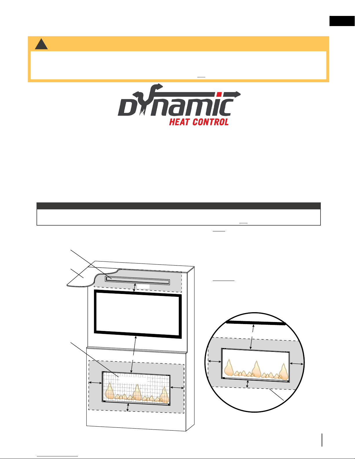
clearances around fireplace
Air outlet
Air Inlet
Glass Guard
6” min.
5.1 Dynamic Heat Control™ (LV optional / LVX included)
WARNING
!
• When fitted with DHC, your appliance, gas/electrical connections, venting and various key components are
hidden behind the wall. It is critical that no screws penetrate the areas illustrated below. Failure to follow
instructions may cause improper operation, damage, personal injury or fire. Always use a stud finder and only
screw into studs (see illustration in “Dynamic Heat Control™ (not available for L models)” section).
PATENT PENDING
Dynamic Heat Control™ is a system for managing the heat produced by the appliance at and around the fireplace
opening. The purpose of Dynamic Heat Control™ is to move the heat away from the fireplace to allow it to
circulate more effectively within the living space. By installing the Dynamic Heat Control™, you gain considerable
benefits:
• Heat is circulated more consistently throughout the living space increasing comfort in front of the fireplace.
• Increased real world efficiency as heat is moved into the room rather than retained inside the fireplace
enclosure.
• Complete flexibility in selection of finish materials.
• Ability to place a TV, sound bar or artwork above the fireplace.
EN
note:
The Dynamic Heat Control™ system should be installed with the appliance. It is not practical as an upgrade
after installation and finishing completed. The Dynamic Heat Control™ system is not available for L models.
DOS
• Screw into studs (see “Dynamic Heat
Control™ (not available for L models”
section).
Ceiling
• Maintain at least the minimum clearances
illustrated.
DON’TS
6” min.
• Place objects too close to air outlet
• Place objects too close to air inlet.
• Screw into the appliance.
Air inlet (LV models)
6” min.
6” min.
Glass Guard
6” min.
6” min.
(LV illustrated w/ optional DHC)
Safety Barrier
2” min.
6” min.
2” min.
(LVX illustrated)
Dynamic Heat
Control™
(LVX models)
Image not to scale.
W415-1713 / 06.30.17
17
Page 18
EN
6.0 maintenance
maintenance
WARNING
!
• Turn off the gas and electrical power before servicing the appliance.
• Appliance may be hot. Do not service until appliance has cooled.
For qualified technicians only:
• Label all wires prior to disconnection when servicing controls. Wiring errors can cause improper and dangerous
operation. Verify proper operation after servicing.
• This appliance and its venting system should be inspected before use and at least annually by a qualified service
person.
• The flow of combustion and ventilation air must not be obstructed.
DOS
• Clean your glass guard assembly (LVX only)
regularly (see “care of glass” section.) Clean your
safety barrier (L and LV only) or regularly to prevent
the build up of excessive lint/dust from carpeting,
pet hair, etc. Simply vacuum using the brush
attachment.
• Always use ammonia-free glass cleaners.
• Service your appliance annually and/or as
required. Service must be conducted by a qualified
technician.
• Keep your appliance area clear and free of
combustible materials, gasoline, or other flammable
vapors and liquids.
• Check to see that the burner ignites completely
on all openings when turned on. A 5 to 10 second
total light-up period is satisfactory. Service as
required.
note:
For any questions and/or concerns regarding your appliance, maintenance and service, please contact your
authorized dealer.
DON’TS
• Attempt to service the electrical or gas
components. Contact a qualified technician.
• Use excessive force.
• Use abrasive cleaners on glass.
• Paint the pilot assembly.
• Place objects too close to the fireplace opening
(all models) or air inlet and air outlet (LV models
fitted with optional DHC and LVX models)
18
W415-1713 / 06.30.17
Page 19

maintenance
!
WARNING
Buff lightly with a clean dry soft cloth to remove accumulated dust or fi ngerprints. Clean both sides of the glass
replacement parts. DO NOT SUBSTITUTE MATERIALS.
• Do not clean glass when hot! Do not use abrasive cleaners to clean glass.
WARNING
6.1 care of glass
!
• Do not clean glass when hot! Do not use abrasive cleaners to clean glass.
important:
The GGA includes two pieces of glass, one of which is floating. Take care never to lift the GGA upside down
or the floating piece of glass can become detached and may break. Always handle the GGA with the mounting
hooks pointing downwards. Should the floating piece of glass ever need to be removed (not recommended for
installation, maintenance and/or cleaning), the front side MUST be marked prior to removal. The GGA floating glass includes special glass coatings from the factory and the glass can only be installed one way around.
Always reassemble the floating glass piece in the same direction as it was removed or the product
performance will be compromised.
Glass Guard Assembly (LVX only) :
A. Unlatch the glass guard assembly and carefully slide
assembly all the way out, see “glass guard removal /
installation (LVX only)” section.
B. Use a duster or a cloth to clean the back and be-
tween the two front panes of glass.
C. Clean the intermediate glass pane.
D. To clean the inside surface of the firebox glass door,
completely remove the glass guard assembly, see
“glass guard removal / installation (LVX only)” sec-
tion. Remove the glass door, see “door removal”
section and follow the instructions below.
EN
Firebox Glass Door :
Do not use ammonia-based cleaners.
after the fi rst 10 hours of operation with a recommended fi replace glass cleaner.
note:
Vinegar-based or ammonia-free glass cleaners have generally demonstrated an ability to provide a clean,
streak free glass surface.
Thereafter clean as required. If the glass is not kept clean permanent discoloration and / or blemishes may
result. Contact you local authorized dealer / distributor for complete cleaning instructions.
Do not contact the inside surface of the glass with razor blades, steel wool or other metallic objects as a thin
layer of metal removed from the object may be deposited onto the coating which results in a discoloured stain
or scratch like mark. More importantly, this can scratch the glass surface thereby reducing its strength.
Do not operate the appliance with broken glass, as leakage of fl ue gases may result.
If the glass should ever crack or break while the fi re is burning, do not open the door until the fi re is out. Do not
operate the appliance until the glass has been replaced. Contact you local authorized dealer / distributor for
Replacement glass/frame assembly shall be replaced as a complete unit as supplied by the appliance
manufacturer.
This appliance is factory equipped with tempered glass (L models only) / ceramic glass (LV / LVX models only).
Use only replacement parts as supplied by the appliance manufacturer. DO NOT SUBSTITUTE MATERIALS.
4
W415-1713 / 06.30.17
19
Page 20
EN
If the appliance is equipped with plated parts, you must clean fi ngerprints or other marks from the plated surfaces
plating is cured, the fi ngerprints and oils will not affect the fi nish and little maintenance is required, just wipe clean
maintenance
FOR SEE-THRU MODELS, REPEAT THE STEPS ABOVE ON THE FIXED SIDE. TO CLEAN THE INNER
SIDE OF THE GLASS DOOR ON THE FIXED SIDE, GO THROUGH THE ACCESS SIDE DOOR AND
CLEAN AS REQUIRED.
access side
fixed side
(Illustration shows view from access side after access side firebox glass door removed.)
6.2 care of plated parts
before operating the appliance for the fi rst time. Use a glass cleaner or vinegar and towel to clean. If not cleaned
properly before operating for the fi rst time, the marks can cause permanent blemishes on the plating. After the
as needed. Prolonged high temperature burning with the door ajar may cause discolouration on plated parts.
note:
The protective wrap on plated parts is best removed when the assembly is at room temperature but this can
be improved if the assembly is warmed, using a hair dryer or a similar heat source.
20
W415-1713 / 06.30.17
Page 21

maintenance
6.3 glass guard assembly (GGA) removal / installation (LVX models only)
WARNING
!
• Allow appliance and glass to cool completely before proceeding.
important:
The glass guard assembly (GGA) installation and/or removal will require 2 people.
6.3.1 removing your GGA (LVX only)
EN
1. To open, release the safety clip from the GGA using the release tool. Push the release tool against bottom
of safety clip until it disengages from GGA. Pull gently on GGA while releasing the safety clip latch.
2. Pull both sides of GGA keeping it parallel to the appliance.
note:
To clean the GGA, see “care of glass” section for Glass Guard Assembly (LVX only) cleaning instructions.
W415-1713 / 06.30.17
21
Page 22

EN
maintenance
3. Remove the screws and washers securing the GGA to the door support brackets (1 per corner).
4. Carefully lift the GGA up and off the door support brackets (2 per side). Set assembly on a clean, soft
surface. Care must be taken to protect the edges of glass and not to dislodge the intermediate floating
glass pane.
22
W415-1713 / 06.30.17
Page 23

maintenance
Heat Rail
(with Gasket)
6.3.2 installing your GGA (LVX models only)
WARNING
!
• Allow appliance to cool completely before proceeding.
note:
If necessary, removing the door trim can make it easier to adjust GGA. Reinstall door trim when finished.
important:
The GGA is supplied with 6 screws that provide slight up/down and tilt adjustment to align glass to finishing
material. If the top of your GGA is not flush to the heat rail (with gasket) on both ends and/or requires an
adjustment, please contact your authorized dealer.
EN
1. Fully extend door mounting brackets of appliance. Carefully place GGA onto supports.
2. Keep brackets tight against GGA and install using 4 screws and washers (provided).
W415-1713 / 06.30.17
23
Page 24

EN
Safety clip
Heat Rail
(with Gasket)
maintenance
3. Slide GGA into the appliance until outer glass panel makes contact with upper gasket. GGA will ‘click’
into safety clips when secure. If GGA does not engage with safety clips, an adjustment may be required.
Before attempting an adjustment, check that the GGA was fully sealed when reinstalled. Adjustment
would have been made during installation. If adjustment is still required, contact an authorized dealer or
qualified technician.
4. Loosen screws and slide in direction to ensure safety clip is engaged while GGA is touching top gasket.
24
W415-1713 / 06.30.17
Page 25

6.4 safety barrier removal (L / LV models only)
WARNING
!
• Allow appliance to cool completely before proceeding.
A. Lift the safety barrier up and out to disengage the four hooks. Reverse steps to install.
SAFETY SCREEN
maintenance
EN
6.5 door trim removal
WARNING
!
• Do not insert fingers in the gap between the door and the framing edge, there is a risk of injury due to the
spring mechanism.
FRONT - ACCESS SIDE
Door trim
A. Remove the door trim by carefully lifting it up and off from behind the bottom frame of the glass
door.
B. Remove the control cover from the appliance by sliding it up and out of the clips of the front cover.
Control
cover
Side view
Door trim
Door frame
LV38-1 Illustrated
W415-1713 / 06.30.17
25
Page 26

EN
maintenance
6.6 firebox glass door removal
A. For door removal, locate the top and bottom door latches. Pull forwards and away to disengage
door latches.
note:
Ensure to leave one hand on the glass door during entire door removal.
B. Tilt the top of the door forwards 90 degrees, then lift it up and out of the door latches.
C. Reverse these steps to re-install the door, ensure the top and bottom door latches are properly
engaged prior to releasing the door.
note:
Ensure the door opens freely and closes sealed.
LV38-1 Illustrated
IMPORTANT: Once latches are engaged, test to make sure that the door is sealed
BACK - FIXED SIDE (SEE THRU ONLY)
note:
The fixed side door operates as as a sealed system that is a critical component of your appliance’s operation.
This should only be removed by a qualified installer.
See-thru models have one fixed door that does not need to be remove by the owner. The inside surface of the
firebox glass (fixed side) can be cleaned from the access side (see “care of glass” section).
6.7 anti-condensation switch
The L models are equipped standard with an anti-condensation switch. The LV / LVX models have the option to
change from an electronic intermittent pilot ignition (IPI) to a standing pilot for cold climates. The anti condensation
control (standing pilot) is located to the left of the control panel. Using your finger, flip the switch up for standing
pilot or down for intermittent pilot ignition.
Turning the ACS switch on will allow the pilot flame to burn continuously. This mode will minimize the
condensation which forms on the inside of the glass when the main burner is first turned on. It will also help the
appliance and vent system stabillize more quickly during the colder months.
During the warmer winter and summer months, the ACS switch should be turned off to minimize fuel
consumption.
26
W415-1713 / 06.30.17
Page 27

7.0 replacements
WARNING
maintenance
!
• Failure to position the parts in accordance with this manual or failure to use only parts specifi cally approved
with this appliance may result in property damage or personal injury.
Contact your dealer for questions concerning prices and policies on replacement parts. Normally, all parts can
be ordered through your Authorized dealer / distributor.
For warranty replacement parts, a photocopy of the original invoice will be required to honour the
claim.
When ordering replacement parts always give the following information:
• Model & Serial Number of appliance
• Installation date of appliance
• Part number
• Description of part
• Finish
For service parts, see your installation manual.
EN
W415-1713 / 06.30.17
27
Page 28

EN
8.0 accessories
accessories
12
13
14
11
10
9
1
2
2
3
3
4
4
5
6
7
8
REF.
#
Porcelain Panel (Rear)
Porcelain End Panels
Nickel Stix
PRPL38 PRPL50 Standard Standard Standard Standard Standard Standard Standard Standard
LDNS LDNS LDNS LDNS LDNS LDNS LDNS LDNS LDNS LDNS
PRPE PRPE Standard Standard Standard Standard Standard Standard Standard Standard
Wrought Iron Globe Kit
Glass Beads
WIGM WIGM WIGM WIGM WIGL WIGL WIGM WIGM WIGL WIGL
MKB_ MKB_ MKB_ MKB_ MKB_ MKB_ MKB_ MKB_ MKB_ MKB_
Mineral Rock Kit
Shore Fire Kit
Birch Log Kit
MRKS MRKM MRKS MRKM MRKL MRKXL MRKS MRKM MRKL MRKXL
SFKM SFKM SFKM SFKM SFKL SFKL SFKS SFKM SFKL SFKL
BLKS BLKM BLKS BLKM BLKL BLKXL BLKS BLKM BLKL BLKXL
Beach Fire Kit
BFKM BFKM BFKM BFKM BFKXL BFKXL BFKS BFKM BFKXL BFKXL
Media Tray
EMT38 EMT50 EMT38 EMT50 Standard Standard Standard Standard Standard Standard
Finishing Trim (Stainless Steel)
Finishing Trim (Black)
FT38SS FT50SS FT38SS FT50SS N/A N/A N/A N/A N/A N/A
FT38K FT50K FT38K FT50K N/A N/A N/A N/A N/A N/A
Surround (Stainless Steel)
Surround (Black)
SFL38SS SLF50SS SLF38SS SLF50SS N/A N/A N/A N/A N/A N/A
SLF38K SLF50K SLF38K SLF50K N/A N/A N/A N/A N/A N/A
Premium Safety Barrier
Premium Safety Barrier
(Stainless Steel)
(Stainless Steel)
(Black)
SSB38SS SSB50SS N/A N/A N/A N/A N/A N/A N/A N/A
PSB38SS PSB50SS PSB38SS PSB50SS PSB62SS PSB74SS N/A N/A N/A N/A
PSB38K PSB50K Standard Standard Standard Standard N/A N/A N/A N/A
Standard Safety Barrier
Description
L38 L50 LV38-1 LV50-2 LV62 LV74 LVX38 LVX50 LVX62 LVX74
Part Number
Stocked
Yes
Yes
Yes
Yes
Yes
Yes
Yes
Yes
Yes
Yes
Yes
Yes
Yes
Yes
Yes
Yes
Yes
28
W415-1713 / 06.30.17
Page 29

important:
BFK
MRK
44
6
52
9
44
8
SFK
WIG
10
44
7
BLK
44
5
44
1
44
2
44344
4
11
12
13
14
authorized Napoleon dealer for a list of accessories suitable for your appliance. Visit the Napoleon website for more information regarding your appliance.
Only accessories specific to your appliance may be installed. Use of other accessories may result in improper operation of your appliance. Contact your
Items may not appear exactly as illustrated
accessories
EN
W415-1713 / 06.30.17
29
Page 30

EN
symptom problem test solution
Flame is a blue,
Blockage in vent. - Remove blockage. In really cold conditions, ice buildup may
occur on the terminal and should be removed as required.
White / grey film forms
on glass.
Sulphur from fuel is being
depos
-
ited on glass, logs, or
-
surfaces.
- Clean the glass with a recommended gas fireplace glass
cleaner.
DO
NOT CLEAN GLASS WHEN HOT.
-
If sulphur deposits are not cleaned off regularly, the glass may
become permanently marked.
Exhaust fumes smelled
in room, headaches.
Appliance may be leaking
exhaust fumes into the room.
- Check firebox glass door was properly reinstalled after cleaning.
If not rectified, turn off appliance. Contact a qualified technician.
Pilot will not light. Makes
noise with no spark at
pilot burner.
No siginal from remote with no
pilot ignition.
- Reprogram receiver code.
- Replace battery holder (including switch), if applicable.
Pilot sparks but will
not light.
Gas supply. - Contact a qualified technician.
Out of propane gas. - Fill the tank.
Remote control (if equipped). - Reset program: hold reset button on remote control and wait
for 2 beeps. Release after second beep. Press small flame
button on remote within 20 seconds, you will hear an
additional beep (this signals a successful reset).
- Replace remote control.
Battery holder (including
switch) is in “off”
position; burner comes
on.
Battery holder (including wall
switch) mounted upside down.
- Reverse.
Battery holder (including switch)
and/or wire is grounding.
- Replace.
- Check for ground (short); repair ground or replace wire.
Faulty wire - Replace.
Remote control and/or
battery holder (including
switch) is not functioning
properly.
Remote control lights but
no spark or flame. (Remote is
locked out).
- Reset by turning power source off then on.
Battery holder (including switch)
or remote has low battery.
- Replace batteries.
Error with synchronizing. - Reset battery holder (including switch) and remote control.
Remote too far away from
battery holder (including switch).
-
Refer to “wiring diagram” section in the Installation manual.
If back up batteries are installed, they must also be
removed to re-program
note:
Flames are very
aggressive.
Door is open. - Ensure door is secured properly. If not rectified, contact a
qualified technician.
Appliance won’t
perform any
functions.
No power to the system.
- Check breaker to verify it’s in the “on” position.
Battery holder (including switch)
in wrong position (if equipped).
- Verify that the 3 position switch on the battery holder (including
switch) is in the remote position (middle).
Battery holder, battery holder
(including switch) and/or remote
control isn’t operational.
-
Check battery power and battery orientation.
lazy, transparent flame
Appliance keeps
shutting off.
High limit switch has tripped. - Your appliance (LV models equipped with DHC or LVX models)
is fitted with a safety switch that shuts your appliance off in the
event that your fireplace and/or enclosure are reaching unsafe
operating temperatures. Contact a qualified technician.
troubleshooting
9.0 troubleshooting
30
W415-1713 / 06.30.17
Page 31

9.1 frequently asked questions
1. I can hear a creaking or tapping noise when my fireplace warms up or cools down. Is there
something wrong?
No, fireplaces are constructed of metal which expands as it heats up and contracts as it cools. This is normal
and has been considered in the design of the product. Noises during warm up and cool down particularly in
cold winter months are no cause for alarm.
2. My fireplace still emits an odor for the first time I use it in the fall. Is there something wrong?
No, when the fireplace has not been used for sometime, house dust can collect on some components and an
odor may be noticed for the first few hours of the season. It’s normally no cause for alarm. The effect can be
minimized with periodic cleaning (see “maintenance” section).
3. How frequently do I need to clean the inside of the fireplace glass door?
After the initial “burn-in”, the glass will only need to be cleaned periodically, depending on the environmental
conditions, the amount of use, etc. We recommend the glass is always cleaned by an authorized installer or
service technician during annual maintenance. The home owner is also able to clean the glass more frequently
when it becomes dirty based on their of pattern of usage, see “maintenance” section.
4. There’s condensation on the glass door(s) of my appliance. Is something wrong?
No, condensation or fog on the glass is normal part of the start-up process that results as a by-product of
combustion. As the firebox heats up, the condensation will start to dissipate. See “maintenance” section for
instructions on cleaning your glass door(s).
5. My remote won’t sync with receiver (battery holder [including switch])and or function anymore?
Ensure your battery holder (including switch) is in the remote (middle) position. Ensure batteries in both the
battery holder (including switch) and the remote control do not need to be replaced. (Upon changing the
batteries in the remote and the receiver, it may be necessary [in rare cases] to replace the remote system.
Remote systems are warrantied for one year).
6. Why does my fireplace need an annual inspection?
Gas fireplaces need an annual inspection in order to maintain safety and reliability. It’s best to get your
fireplace checked each spring; that way you have a flawlessly functioning fireplace all year round when you
need it. This is a very important practice, which many overlook. Because gas fireplaces burn clean and are
very easy to take care of, some assume that this means it doesn’t need cleaning. Safety is always number
one when it comes to enjoying a roaring fire in your living space. By having an annual inspection, you ensure
that your beautiful fireplace is running at peak efficiency for whenever you need that glowing comfort.
Maintenance is also required to ensure all warranty related concerns within the limitations and conditions are
still covered.
7. Will my appliance operate in the event of a power failure?
Your appliance is equipped with a battery back-up (battery holder for L models and battery holder [including
switch for LV / LVX models). If installed, the batteries will allow the pilot and main burner to operate. However,
the lights will not operate. Additionally, if your appliance has been installed with a GPV (Gas Power Vent), your
appliance will not operate.
8. Should I leave my ACS / pilot on or off?
Anti-condensation switches (ACS) are used in cooler climates on electronic ignition models where there is
an increased potential for moisture from outside and products of combustion to condense onto the interior
surfaces of the firebox, glass and pilot assembly when the burner turns off. The ACS reduces the potential
for corrosion and staining of the glass. An additional benefit of ACS utilization is that it will help keep draft
established when the burner is turned off and prevents a cold air block from occurring. This allows for quicker
re-ignitions with fewer restarts, especially during colder weather. The ACS/pilot should be turned off in warmer
climates or summer months to avoid wasting gas.
If in doubt, contact your authorized dealer or a qualified technician.
faq
EN
For more FAQ’s, visit our website: http://napoleonfireplaces.com/faqs.
W415-1713 / 06.30.17
31
Page 32

EN
Napoleon products are manufactured under the strict Standard of the world recognized ISO 9001 : 2008 Quality Assurance
warranty
10.0 warranty
Certifi cate.
Napoleon products are designed with superior components and materials assembled by trained craftsmen who take great
pride in their work. The burner and valve assembly are leak and test-fi red at a quality test station. The complete appliance is
again thoroughly inspected by a qualifi ed technician before packaging to ensure that you, the customer, receives the quality
product that you expect from Napoleon.
Napoleon Gas Appliance President’s Lifetime Limited Warranty
The following materials and workmanship in your new Napoleon gas appliance are warranted against defects for as
long as you own the appliance. This covers: combustion chamber, heat exchanger, stainless steel burner, Phazer™ logs
and embers, rocks, ceramic glass (thermal breakage only), gold plated parts against tarnishing, porcelainized enameled
components and aluminum extrusion trims.*
Electrical (110V and millivolt) components and wearable parts are covered and Napoleon will provide replacement parts free
of charge during the fi rst year of the limited warranty. This covers: blowers, gas valves, thermal switches, switches, wiring,
remote controls, ignitors, gaskets and pilot assemblies.*
Labour related to warranty repair is covered free of charge during the fi rst year. Repair work, however, requires the prior
approval of an authorized company offi cial. Labour costs to the account of Napoleon are based on a predetermined rate
schedule and any repair work must be done through an authorized Napoleon dealer.
* Construction of models vary. Warranty applies only to components included with your specifi c appliance.
Conditions and Limitations
Napoleon warrants its products against manufacturing defects to the original purchaser only. Registering your warranty is
not necessary. Simply provide your proof of purchase along with the model and serial number to make a warranty claim.
Napoleon reserves the right to have its representative inspect any product or part thereof prior to honouring any warranty
claim. Provided that the purchase was made through an authorized Napoleon dealer your appliance is subject to the
following conditions and limitations:
Warranty coverage begins on the date of original installation. This factory warranty is non-transferable and may not
be extended whatsoever by any of our representatives. The gas appliance must be installed by a licensed, authorized
service technician or contractor. Installation must be done in accordance with the installation instructions included with
the product and all local and national building and fi re codes. This limited warranty does not cover damages caused by
misuse, lack of maintenance, accident, alterations, abuse or neglect, and parts installed from other manufacturers will
nullify this warranty. This limited warranty further does not cover any scratches, dents, corrosion or discoloring caused by
excessive heat, abrasive and chemical cleaners nor chipping on porcelain enamel parts, mechanical breakage of Phazer™
logs and embers. This warranty extends to the repair or replacement of warranted parts which are defective in material or
workmanship provided that the product has been operated in accordance with the operation instructions and under normal
conditions. After the fi rst year, with respect to this President’s Lifetime Limited Warranty, Napoleon may, at its discretion,
fully discharge all obligations with respect to this warranty by refunding to the original warranted purchaser the wholesale
price of any warranted but defective part(s).
32
Napoleon will not be responsible for installation, labour, or any other expenses related to the reinstallation of a warranted
part and such expenses are not covered by this warranty. Notwithstanding any provisions contained in the President’s
Lifetime Limited Warranty, Napoleon’s responsibility under this warranty is defi ned as above and it shall not in any event
extend to any incidental, consequential or indirect damages. This warranty defi nes the obligations and liability of Napoleon
with respect to the Napoleon gas appliance and any other warranties expressed or implied with respect to this product,
its components or accessories are excluded. Napoleon neither assumes, nor authorizes any third party to assume, on
its behalf, any other liabilities with respect to the sale of this product. Napoleon will not be responsible for: over-fi ring,
downdrafts, spillage caused by environmental conditions such as rooftops, buildings, nearby trees, hills, mountains,
inadequate vents or ventilation, excessive venting confi gurations, insuffi cient makeup air, or negative air pressures which
may or may not be caused by mechanical systems such as exhaust fans, furnaces, clothes dryers, etc. Any damages to
the appliance, combustion chamber, heat exchanger, plated trim or other components due to water, weather damage, long
periods of dampness, condensation, damaging chemicals or cleaners will not be the responsibility of Napoleon. All parts
replaced under the President’s Limited Lifetime Warranty Policy are subject to a single claim.
During the fi rst 10 years Napoleon will replace or repair the defective parts covered by the lifetime warranty at our discretion
free of charge. From 10 years to life, Napoleon will provide replacement parts at 50% of the current retail price. All parts
replaced under the warranty will be covered for a period of 90 days from the date of their installation. The manufacturer
may require that defective parts or products be returned or that digital pictures be provided to support the claim. Returned
products are to be shipped prepaid to the manufacturer for investigation. If a product is found to be defective, the
manufacturer will repair or replace such defect. Before shipping your appliance or defective components, your dealer must
obtain an authorization number. Any merchandise shipped without authorization will be refused and returned to sender.
Shipping costs are not covered under this warranty. Additional service fees may apply if you are seeking warranty service
from a dealer. Warranty labour allowance is only for the replacement of the warranted part. Travel, diagnostic tests, shipping
and other related charges are not covered by this warranty.
All specifi cations and designed are subject to change without prior notice due to on-going product improvements. Napoleon is a registered
trademark of Wolf Steel Ltd.
W415-1713 / 06.30.17
Page 33

11.0 service history
service history
EN
Appliance Service History
This appliance must be serviced annually depending on usage
Date Dealer Name Service Technician Name Service Performed Special Concerns
W415-1713 / 06.30.17
33
Page 34

NAPOLEON CELEBRATING OVER 40 YEARS
OF HOME COMFORT PRODUCTS
7200, Route Transcanadienne, Montréal, Québec H4T 1A3
24 Napoleon Road, Barrie, Ontario, Canada L4M 0G8
214 Bayview Drive, Barrie, Ontario, Canada L4N 4Y8
103 Miller Drive, Crittenden, Kentucky, USA 41030
Phone: 1-866-820-8686
napoleonproducts.com
Page 35

FRANÇAIS
MANUEL DU
PROPRIÉTAIRE
Séries Acies / Vector / Luxuria
Modèle Luxuria illustrée.
CONSIGNES DE SÉCURITÉ
!
AVERTISSEMENT
RISQUE D’INCENDIE OU D’EXPLOSION
Incapacité à suivre ces avertissements exactement peuvent entraîner de grave blessures, des pertes de vie ou des dommages
matériels
- N’entreposez pas et n’utilisez pas d’essence ou autres liquides et vapeurs inflammables à proximité de cet appareil ou tout
autre appareil.
- QUE FAIRE SI VOUS DÉTECTEZ UN ODEUR DE GAZ:
• N’allumez aucun appareil.
• Ne touchez à aucun téléphone dans votre immeuble.
• Appelez immédiatement votre fournisseur de gaz d’un téléphone dans votre immeuble.
• Si vous ne pouvez pas rejoindre votre fournisseur de gaz, appelez le service des incendies.
- L’installation et l’entretien doivent être faits par un installateur qualifié, une agence d’entretien ou le fournisseur.
Wolf Steel Ltd., 24 Napoleon Rd., Barrie, ON, L4M 0G8 Canada / 103 Miller Drive, Crittenden, Kentucky, USA, 41030
Téléphone 1 (866) 820-8686 • www.napoleonfoyers.com • hearth@napoleonproducts.com
Pour l’utilsation intérieure seulement
W415-1713 / 06.30.17
Page 36

consignes de sécurité
!
AVERTISSEMENT
FR
36
• Cet appareil est chaud lorsqu’il fonctionne et peut
causer de grave brûlures en cas de contact.
• Toute modifi cation apportée à cet appareil ou aux
contrôles peut être dangereux et est interdit.
• Ne faites pas fonctionner l’appareil avant d’avoir
lu et compris les instructions d’opération. Omettre
d’utiliser l’appareil selon les instructions dopération
pourrait causer un incendie ou des blessures.
• Risque d’incendie ou d’asphyxie. Ne faites pas
fonctionner l’appareil avec la vitre retirée.
• Ne branchez pas la soupape à du courant 110
volts.
• Risque de brûlures. L’appareil doit être éteint et
refroidi avant d’effectuer un entretien.
• N’installez pas de composants endommagés ou
incomplets ni des composants substituts.
• Risque de coupures et d’érafl ures. Portez des
gants protecteurs et des lunettes de sécurité lors
de l’installation. Les bordures des pièces de métal
peuvent être coupantes.
• Les enfants et les adultes devraient être informés
des dangers que posent les températures
de surface élevées et se tenir à distance afi n
d’éviter des brûlures ou que leurs vêtements ne
s’enfl amment.
• Les jeunes enfants doivent être surveillés
attentivement lorsqu’ils sont dans la même
pièce que l’appareil. Les jeunes enfants et autres
personnes à risque sont sujets aux brûlures
accidentelles. Une barrière de protection est
recommandée si des individus à risque se trouvent
dans la maison. Afi n de renstreindre l’accès à
l’appareil, installez une barrière de protection
ajustable pour garder les jeunes enfants ou autres
personnes à risque hors de la pièce et loin des
surfaces chaudes.
• Les vêtements et autres matériaux combustibles ne
doivent pas être posés sur l’appareil ou à proximité.
• En raison des températures élevées, l’appareil
devrait être placé loin des endroits passants et loin
des meubles et des rideaux.
• Assurez-vous de disposer de mesures de sécurité
adéquates pour empêcher les jeunes enfants de
toucher aux surfaces chaudes.
• Même une fois que l’appareil est éteint, la vitre et/
ou le pare-étincelles demeureront chauds pendant
un temps prolongé.
• Consultez votre détaillant local de foyer pour
connaître les grillages de sécurité et les écrans
offerts pour protéger les enfants des surfaces
chaudes. Ces grillages de sécurité et ces écrans
doivent être fi xés au plancher.
• Tout grillages de sécurité, écrans ou barrières
enlevès pour faire l’entretien devront être remis en
place avant d’utiliser l’appareil.
• Cet appareil est un appareil à gaz ventilé. Ne brûlez
pas de vois ou autres matériaux dans cet appareil.
W415-1713 / 06.30.17
• L’emplacement de l’appareil doit être gardé libre de
tous matériaux combustibles, essence ou d’autres
liquides et vapeurs infl ammables.
• N’utilisez pas cet appareil si une partie quelconque
a été submergée. Contactez immdiatement un
technicien de service qualifi é pour inspecter
l’appareil et pour remplacer toute pièce du système
de contrôle et du contrôle du gaz qui aurait été
submergée.
• Ne pas opérer l’appareil lorsque la porte vitrée est
enlvée, fi ssurée ou brisée. Le remplacement de
la vitre devra être effectué par un technicien de
service certifi é ou qualifi é.
• Ne frappez pas et ne claquez pas la porte vitrée de
l’appareil.
• Lorsqu’il est équippé avec les portes d’évacuation
de pression, les portes doivent demeurer fermées
pendant le fonctionnement de l’appareil afi n
d’empêcher les gaz de combustion contenant
du monoxyde de carbone de s’infi ltrer dans la
maison. La température des gaz de combustion
s’échappant par ces ouvertures peut aussi
causer les matériaux combustibles avoisinants à
surfchauffer et à prendre feu.
• Seules les portes/façades certifi ées pour cet
appareil peuvent être utilisées avec cet appareil.
• Gardez les matériaux d’emballage hors de la portée
des enfants et mettez ces matériaux au rebut de
façon sécuritaire. Comme tous les emballages de
plastique, ces matériaux ne sont pas des jouets et
doivent demeurer hors la portée des enfants et des
bébés.
• Comme dans le cas de tout appareil à combustion,
il est recommandé de faire inspecter et entretenir
votre appareil régulièrement. De même, installez un
détecteur de monoxyde de carbone dans la pièce
pour vous protéger, ainsi que votre famille, contre
les intoxications.
• Assurez-vous de respecter les dégagements aux
matériaux combustibles lorsque vous installez un
manteau ou des tablettes au-dessus de l’appareil.
Les températures élevées sur le mur ou de l’air audessus de l’appareil peuvent faire fondre, décolorer
ou endommager les décorations, les téléviseurs ou
autres composants électroniques.
• Une barrière conçu à réduire le risque de brûlures
causées par le verre chaud est fourni avec
l’appareil et sera installé.
• Si la barrière est endommagée, elle devra
être remplacée par la barrière conçu par le
manufacturier pour cet appareil.
• L’installation et la réparation devraient être
effectuées par un technicien qualifi é. L’appareil
et son système d’évacuation devraient être
inspectés avant l’utilisation initiale et au moins
une fois l’an par un professionel qualifi é. Un
nettoyage plus fréquent peut être requis en
raison de la poussière excessive laissée par les
moquettes, les couvertures, etc. Il est impératif que
les compartiments de contrôle, le brûleur et les
passages de circulation d’air soient gardés propres
afi n de fourni une combustion et une circulation
d’air adéquates.
Page 37

HOT GLASS WILL CAUSE
BURNS.
DO NOT TOUCH GLASS UNTIL
COOLED.
NEVER ALLOW CHILDREN TO
TOUCH GLASS.
!
DANGER
AVERTISSEMENT
A barrier designed to reduce the risk of burns from
the hot viewing glass is provided with this appliance
and shall be installed for the protection of children
and other at-risk individuals.
LA VITRE CHAUDE CAUSERA
DES BRÛLURES.
NE PAS TOUCHER LA VITRE
AVANT QU’ELLE AIT REFROIDI.
NE JAMAIS LAISSER LES
ENFANTS TOUCHER LA VITRE.
HOT GLASS WILL CAUSE
BURNS.
DO NOT TOUCH GLASS UNTIL
COOLED.
NEVER ALLOW CHILDREN TO
TOUCH GLASS.
!
WARNING
!
AVERTISSEMENT
Les foyers gé-
Fireplaces
generate radiant
nèrent la chal-
heat. Do not put
eur radiante. Ne
objects in front
placez pas des
of the appliance
objets devant
(minimum
l’appareil (dis-
distance of 4
tance minimum
feet).
de 48 po).
l'espace vide
AVERTISSEMENT
!
La zone située au-dessus de la chemi-
née devient chaude, (sauf si l’appareil
est équipé d’un système de Dynamic
Heat Control™ de Napoléon). Objets
combustibles ne doivent jamais être
placés dans ce domaine. Distance minimale, se référer au manuel d’installation
ou de votre revendeur agréé.
!
LA VITRE CHAUDE CAUSERA
DES BRÛLURES.
NE PAS TOUCHER LA VITRE
AVANT QU’ELLE AIT REFROIDI.
NE JAMAIS LAISSER LES
ENFANTS TOUCHER LA VITRE.
Une barriére conçu à réduire le risque de brûlures
causées par le verre chaud est fourni avec l’appareil
et sera installé pour la protection des enfants et
d’autres personnes à risque.
FR
note:
Dynamic Heat Control™ est en option sur la série Vector (modèles LV) et inclus dans la série Luxuria (modèles
LVX). Dynamic Heat Control™ n’est pas disponible pour les modèles L. [BREVET DÉPOSÉ]
AVERTISSEMENT
!
Si équipé avec Dynamic Heat Control™
(DHC), NE PAS COUVRIR OU PLACE
POINTS À PRISE D’AÉRATION!*
RISQUE D’INCENDIE !
L’air qui sort de la sortie d’air DHC
est très chaud. NE JAMAIS PLACER
OU PERMETTRE AUX ÉLÉMENTS DE
TOMBER À L’INTÉRIEUR DU SORTIE
* La sortie d’air DHC est présentée à
l’avant de l’enceinte de la cheminée (voir
illustration), mais il peut être situé à hauteur du plafond, il peut être dans la salle
derrière ou dans les deux chambres.
D’AIR DHC.
W415-1713 / 06.30.17
37
Page 38

bienvenue
FR
félicitations
Napoléon tient fièrement à votre confort domestique. Nous sommes fiers de dire que nos produits continuellement
surpassent les normes de l’industrie et notre source d’inspiration c’est vous! Plus que tout, nous voulons vous
faire sentir confiant dans le choix de Napoléon pour votre maison. Nos produits sont conçus pour fournir cette
confiance et s’assurer que chaque produit de Napoléon est incomparable.
Les produits Napoléon sont conçus avec des composants et des matériaux de qualité supérieure, assemblés par
des artisans qualifié qui sont fiers de leur travail.
Une barrière conçu à réduire le risque de brûlures à partir de la vitre chaud est à condition que avec l’appareil et
doit être installés.
Votre appareil de Napoléon a été soigneusement inspecté par un technicien qualifié avant d’être emballé pour
garantir que vous, le client, recevez le produit de qualité dont vous vous attendez de Napoléon.
Détaillant: Renseignez votre information (ou carte de visite) et l’information de l’installation de l’appareil
ci-dessous.
Nom du détaillant:
Location du détaillant:
Téléphone du détaillant:
E-mail du détaillant:
Client:
Addresse du Client:
Date d’Installation:
Location de l’appareil:
Installateur:
Information du Détaillant
Nº de série:
Modèle:
Gaz Naturel:
Acies
L38N
L50N
Vector
LV38N-1
LV50N-2
LV62N
LV74N
Luxuria
LVX38N
LVX50N
LVX62N
LVX74N
Vector ou
Luxuria
Dynamic Heat Control™ installé (Optionnel pour LV / includ pour LVX)*
Détaillant: Location du Carte de
Visite
Propane:
L38N2
L50N2
LV38N2-1
LV50N2-2
LV62N2
LV74N2
LVX38N2
LVX50N2
LVX62N2
LVX74N2
L38P
L50P
LV38P-1
LV50P-2
LV62P
LVX38P
LVX50P
LVX62P
*Non disponible pour les modèles L
L38P2
L50P2
LV38P2-1
LV50P2-2
LV62P2
LVX38P2
LVX50P2
LVX62P2
38
W415-1713 / 06.30.17
Page 39

table des matières
félicitations 38
1.0 apprendre à connaître votre appareil 40
1.1 accès de contrôles 41
1.2 location de la plaque d’homologation / instructions d’allumage 42
2.0 faites fonctionner votre appareil 43
2.1 utilisation de votre appareil (L seulement) 43
2.3 composants arrêt / marche 43
2.2 utilisation de votre appareil (LV / LVX seulement) 43
2.3.1 changeant les piles dans le bloc-piles (modèles L seulement) 44
2.4 service de couverture (modèles L seulement) 44
2.4.1 changeant les piles dans la télécommande / support du batteries inclus
commutateur 45
3.0 dessin général de la télécommande 46
4.0 fonctionnement de la télécommande (optionnel pour modèles L ) 47
4.1 fonctionnement de la télécommande 47
4.2 afficheur de température 47
4.3 hauteur de la flamme 47
4.4 fonction de sécurité pour enfants 47
4.5 LEDs 47
4.6 veilleuse gradateur 47
4.7 la sélection pilote continu / pilote intermittent (CPI / IPI) 48
4.8 faible piles / le by-pass manuel 48
4.9 en cas de panne de courant 48
4.10 l’application Contrôleur eFIRE (optionnel pour les modèles L) 48
4.11 contrôle de lumière LED (modèles LV / LVX seulement) 49
5.0 dégagements autour de l’appareil 50
5.1 Dynamic Heat Control™ (LV optionnel / LVX includ) 51
6.0 entretien 52
6.1 soins de la vitre 53
6.2 soins des pièces plaquées 54
6.3 enlèvement/installation de l’ensemble du protection de verre (GGA) (modèles LVX seulement) 55
6.3.1 enlevant votre GGA (modèles LVX seulement) 55
6.3.2 installant votre GGA (modèles LVX seulement) 57
6.4 enlèvement de la barrière de protection (modèles L / LV seulement) 59
6.5 enlèvement de la garniture de la porte 59
6.7 enlèvement de la porte 60
6.6 interrupteur contre la condensation 60
7.0 rechanges 61
8.0 accessoires 62
9.0 guide de dépannage 64
9.1 questions fréquente 65
10.0 garantie 66
11.0 historique d’entretien 67
FR
L’icône du camera indique que les vidéos sont disponibles comme une référence supplémentaire, visitez
http://mynapoleon.napoleonproducts.com/download/index/44/1
W415-1713 / 06.30.17
39
Page 40

1.0 apprendre à connaître votre appareil
apprendre à connaître votre appareil
FR
Ce manuel est écrit pour une série complète de cheminées linéaires qui ont une gamme de différentes caractéristiques et spécifications. Avant de lire ce manuel, assurez-vous de que savoir quel modèle de cheminée que vous
avez. Ces informations vont ont été remplies sur la plaque signalétique qui est fixée en permanence au foyer (voir
la section « vue d’ensemble de l’appareil »).
Ce manuel s’adresse au
• Séries Acies (préfixe du numéro de modèle « L »)
• Séries Vector (préfixe du numéro de modèle « LV »)
• Séries Luxuria (préfixe du numéro de modèle « LVX »)
Si nécessaire, plus d’information technical est inclus dans le manuel d’installation de votre appareil.
L’information tout au long de ce manuel est censée être correctes au moment de l’impression. Wolf Steel Ltd. se
réserve le droit de changer ou modifier toute information dans ce manuel à tout moment sans préavis. Modifications, autres que l’éditorial sont signalées par un trait vertical dans la marge.
Visitez le site web de Napoléon pour la version le plus récent de votre manuel.
Location de
soupape / plaque
Ensemble du
protection de
verre (GGA)
(LVX
seulement)
Barrière de
protection
(L / LV
seulement)
Garniture
de la
porte
Porte vitrée
du foyer
Support muni
du GGA
(LVX
seulement)
d’homologation
/ bloc-piles
(L seulement)
instructions
d’allumage
Rail de chaleur
(LVX seulement)
Certaines fonctionnalités et certains composants illustrés peuvent varier selon votre modèle.
40
W415-1713 / 06.30.17
Couvercle de contrôle
BrûleurPilote
Modèle simple face illustrée.
Support de batterie
(inclus commutateur)
Page 41

apprendre à connaître votre appareil
PRE-FINISHING
Le terme « accès côté » est utilisé dans le présent manuel et désigne le côté ouvert de la cheminée où se trouve la
porte vitrée de chambre de combustion.
Si l’appareil est transparent, il existe des portes vitrées foyer des deux côtés de l’appareil. Une de ces portes est
fixe et ne peut pas être supprimée. Le côté d’accès peut être identifié par l’emplacement du pilote.
FR
emplacement
du pilote
côté d’accès côté fixe
emplacement
du pilote
1.1 accès de contrôles
L’accès aux contrôles peut être fait par l’intermédiaire du foyer après enlever la barrière de protection (modèles L
/ LV) ou l’ensemble du protection de verre (modèles LVX), la porte vitrée, garniture de la porte et la couvercle de
contrôle (voir la section « entretien » pour les instructions d’enlèvement pour ses composants).
SOUPAPE
VALVE
CONTROL
MODULE
ELECTRICAL
PRE-FINISHING
ACCESS PANEL
W415-1713 / 06.30.17
41
Page 42

apprendre à connaître votre appareil
ÉCHANTILLON
FR
1.2 location de la plaque d’homologation / instructions d’allumage
La plaque d’homologation et les instructions d’allumage sont attachés à une chaìnette située à gauche des
contrôles de l’appareil, près de la soupape (côté accès). Retirez la barrière de protection ou l’ensemble du
protection de verre pour accéder aux contrôles de l’appareil.
Pour remettre la barrière de protection ou l’ensemble de protection de verre, glissez les instructions près des
contrôles de l’appareil et réinstallez l’écran de protection ou glissez l’ensemble du protection de verre en position
verrouillée.
WARNING:
KEEP BURNER AND CONTROL
COMPARTMENT CLEAN. SEE
INSTALLATION AND OPERATING
INSTRUCTIONS MANUAL.
APPLIANCE NEEDS FRESH
AIR FOR SAFE OPERATION
AND MUST BE INSTALLED
WITH ADEQUATE PROVISIONS
FOR COMBUSTION
AND VENTILATION AIR.
GARDEZ LE BRÛLEUR ET LE
COMPARTIMENT DES
CONTRÔLES PROPRES.
CONSULTEZ LE MANUEL
D’INFORMATION ET
D’INSTALLATION. PAR
MESURE DE SÉCURITÉ.
CET APPAREIL DOIT
ÊTRE ALIMENTÉE EN AIR
FRAIS ET AVEC SUFFISANT
D’AIR COMBURANTET
DE VENTILATION.
CERTIFIED TO CANADIAN AND AMERICAN NATIONAL STANDARDS: CSA 2.22-2016 AND ANSI Z21.50-2016 FOR VENTED DECORATIVE GAS FIREPLACES.
CERTIFIÉ SELON LES NORMES NATIONALES CANADIENNES ET AMÉRICAINES: CSA 2.22-2016 ET ANSI Z21.50-2016 POUR LES APPAREILS À GAZ VENTILÉS DÉCORATIFS.
DIRECT VENT, VENTED GAS FIREPLACES. APPROVED FOR BEDROOM, BATHROOM AND BED-SITTING
ROOM INSTALLATION. SUITABLE FOR MOBILE HOME INSTALLATION IF INSTALLED IN ACCORDANCE
WITH THE CURRENT STANDARD CAN/CSA Z240MH SERIES GAS EQUIPPED MOBILE HOMES,
IN CANADA OR IN THE UNITED STATES THE MANUFACTURED HOME CONSTRUCTION AND
SAFETY STANDARD, TITLE 24 CFR, PART 3280. WHEN THIS US STANDARD IS NOT
APPLICABLE USE THE STANDARD FOR FIRE SAFETY CRITERIA FOR MANUFACTURED HOME
INSTALLATIONS, SITES AND COMMUNITIES, ANSI / NFPA 501A. THIS APPLIANCE MUST BE
INSTALLED IN ACCORDANCE WITH LOCAL CODES, IF ANY; IF NONE, FOLLOW THE CURRENT
ANSI Z223.1, OR CSA B149, INSTALLATION CODES.
FOLLOW THE INSTALLATION INSTRUCTIONS LOCATED IN THE INSTALLATION MANUAL.
MANIFOLD PRESSURE: 3.5 INCHES W.C. (NG)
PRESSION AU COLLECTEUR: 3.5" D'UNE
COLONNE D'EAU(GN)
9700539 (WSL) 4001657 (NGZ)
MIN SUPPLY PRESSURE: 4.5" W.C.(NG)
4001658 (NAC) 4001659 (WUSA)
PRESSION D'ALIMENTATION MIN: 4.5" D'UNE
LVX38N CLVX38N MODEL CLVX38P LVX38P
COLONNE D'EAU (GN)
MAX. SUPPLY PRESSURE: 7"* W.C. (NG)
PRESSION D'ALIMENTATION MAX: 7"* D'UNE
COLONNE D'EAU (GN)
*MAXIMUM INLET PRESSURE NOT TO EXCEED 13".
*PRESSION D'ALIMENTATION MAXIMALE NE DEVAIT PAS DÉPASSER 13".
NOT FOR USE WITH SOLID FUEL. FOR USE WITH GLASS
DOORS CERTIFIED WITH THIS APPLIANCE ONLY.
WARNING:DO NOT ADD ANY MATERIAL TO THE APPLIANCE, WHICH WILL COME IN CONTACT WITH THE FLAMES, OTHER
THAN THAT SUPPLIED BY THE MANUFACTURER WITH THE APPLIANCE.
MINIMUM CLEARANCE TO COMBUSTIBLE MATERIALS / DÉGAGEMENTS MINIMAUX DES MATÉRIAUX COMBUSTIBLES:
TOP, SIDES & BACK: PER STAND OFF SPACERS FOR FRAMING AND FINISHING MATERIALS. FOR FINISHING MATERIALS
SEE INSTALLATION MANUAL. DESSUS, CÔTÉS & ARRIÈRE: SELON LES ESPACEURS DE DÉGAGEMENT POUR LES MATÉRIAUX
D'OSSATURE SELON LA MANUEL DE PROPRIÉTAIRE POUR LES MATÉRIAUX DE FINITION.
TOP/ DESSUS 0" RECESSED DEPTH ONE SIDED/ PROFONDEUR D'ENCASTRE UNE FACE 17 15/16"
FLOOR / PLANCHER 0" RECESSED DEPTH SEE THRU/ PROFONDEUR D'ENCASTRE TRAVERS 16 3/16"
SIDES / CÔTÉS 0" BACK / ARRIÈRE 0"
VENT TOP / DESSUS DU CONDUIT D’ÉVENT 3"
VENT SIDES & BOTTOM / CÔTÉS ET DESSOUS DU CONDUIT D'ÉVENT 2"
VERTICAL VENT / CONDUIT D’ÉVENT VERTICAL 1"
MANTEL / TABLETTE 0" *
TOP, SIDES & BACK: PER STAND OFF SPACERS FOR FRAMING MATERIALS. FOR FINISHING MATERIALS
SEE INSTALLATION MANUAL. DESSUS, CÔTÉS & ARRIÈRE: SELON LES ESPACEURS DE DÉGAGEMENT POUR LES MATÉRIAUX
D'OSSATURE SELON LA MANUEL DE PROPRIÉTAIRE POUR LES MATÉRIAUX DE FINITION.
* MAXIMUM HORIZONTAL EXTENSION / L'EXTENSION HORIZONTALE MAXIMALE: 2". SEE INSTALLATION MANUAL FOR
GREATER EXTENSIONS. RÉFÉRER AU MANUEL D'INSTRUCTION POUR DES EXTENSIONS PLUS GRANDES.
SEE INSTALLATION MANUAL FOR MINIMUM AND MAXIMUM VENT LENGTHS. RÉFÉRER AU MANUEL D'INSTALLATION
DE PROPRIÉTAIRE POUR LES LONGUEURS D'ÉVACUATION MINIMALE ET MAXIMALE.
WOLF STEEL LTD.
IMPROPER INSTALLATION,
ADJUSTMENT, ALTERATION,
SERVICE OR MAINTENANCE
CAN CAUSE PROPERTY DAMAGE,
PERSONAL INJURY OR LOSS OF
LIFE. REFER TO OWNER’S
MANUAL. INSTALLATION AND
SERVICE MUST BE PERFORMED
BY A QUALIFIED INSTALLER,
SERVICE AGENCY OR THE
GAS SUPPLIER.
ATTENTION:
UN INSTALLATION OU UNE
MODIFICATION INAPPROPRIÉE
DU RÉGLAGE, DU SERVICE ET DE
L’ENTRETIEN POURRAIENT ÊTRE
LA CAUSE DE DOMMAGES À LA
PROPRIETÉ DE BLESSURES
CORPORELLES OU MÊME LA
MORT. CONSULTER LE MANUEL
D’INFORMATION, L’INSTALLATION
ET LE SERVICE DOIVENT
ÊTRE EXECUTÉS PAR UN
INSTALLATEUR QUALIFIÉ POUR
LE GAZ, UNE ENTREPRISE DE
SERVICE OU LE FOURNISSEUR
DE GAZ SEULEMENT.
FOR USE WITH SAFETY BARRIER W010-4186.
0-4500FT (0-1370m) ALTITUDE / ÉLÉVATION 0-4500FT (0-1370m)
32,000 BTU/h INPUT / ALIMENTATION 32,000 BTU/h
REDUCED INPUT / ALIMENTATION RÉDUITE
22,000 BTU/h
24 NAPOLEON ROAD, BARRIE, ON, L4M 0G8 CANADA
CAUTION:
HOT WHILE OPERATING. DO NOT TOUCH.
KEEP CHILDREN, CLOTHING, FURNITURE,
GASOLINE OR OTHER FLAMMABLE VAPORS
AWAY.
AVERTISSEMENT:
L’APPAREIL EST CHAUD PENDANT SON
FONCTIONNEMENT. LES ENFANTS, LES
VÉTEMENTS, LES MEUBLES, L’ESSENCE ET
AUTRES LIQUIDES QUI ÉMETTENT DES GAZ
VOLATILS INFLAMMABLES DOIVENT
ÉTRE TENUS ÉLOIGNES DE L’APPAREIL.
“This appliance is only for use with the type(s)
of gas indicated on the rating plate and may
be installed in an aftermarket, permanently
located, manufactured home (USA only) or
mobile home, where not prohibited by local
codes. See owner’s manual for details. This
appliance is supplied with a conversion kit.”
«Cet appareil doit être utilisé uniquement
avec les types de gaz indiqués sur la plaque
signalétique et peut être installé dans une
maison préfabriquée (É.-U. seulement) ou
mobile installée à demeure si les règlements
locaux le permettent. Voir la notice de
l’utilisateur pour plus de renseignements. Une
trousse de conversion est fournie avec cet
appareil.»
FOYER À GAZ VENTILÉ. HOMOLOGUÉ POUR INSTALLATION DANS UNE CHAMBRE À COUCHER, UNE
SALLE DE BAIN ET UN STUDIO. APPROPRIÉ POUR INSTALLATION DANS UNE MAISON MOBILE SI
SON INSTALLATION CONFORME AUX EXIGENCES DE LA NORME CAN/CSA Z240MH SÉRIE DE
MAISONS MOBILES ÉQUIPÉES AU GAZ, EN VIGUEUR AU CANADA OU AUX ÉTATS-UNIS DE LA
NORME DE SÉCURITÉ ET DE CONSTRUCTION DE MAISONS MANUFACTURÉES, TITRE 24
CFR, SECTION 3280. DANS LE CAS OU CETTE NORME D'ÉTATS-UNIS NE PEUT ÊTRE
APPLIQUÉE, SE RÉFÉRER A LA NORME RELATIVE AU CRITÈRE DE MESURES DE SÉCURITÉ
CONTRE L'INCENDIE POUR LES INSTALLATIONS DANS LES MAISONS MANUFACTURÉS, LES
SITES ET LES COMMUNAUTÉS, ANSI/NFPA 501A. CODES. INSTALLER L’APPAREIL SELON LES
CODES OU RÈGLEMENTS LOCAUX, OU EN L’ABSENCE DE TELS RÈGLEMENTS, SELON LES
CODES D’INSTALLATION ANSI Z223.1 OU CSA-B149 EN VIGUER.
BARRIÈRE W010-4186. SUIVEZ LES INSTRUCTIONS D'INSTALLATION QUI SE TROUVENT DANS LE
25,000 BTU/h
P4
40.2%40.2%
UN COMBUSTIBLE SOLIDE NE DOIT PAS ÊTRE UTILISÉ AVEC
CET APPAREIL. UTILISER AVEC LES PORTES VITRÉES
HOMOLOGUÉES SEULEMENT AVEC CETTE APPAREIL.
AVERTISSEMENT: N’AJOUTEZ PAS A CET APPAREIL AUCUN MATÉRIAU DEVANT ENTRER EN CONTACT AVEC
LES FLAMMES AUTRE QUE CELUI QUI EST FOURNI AVEC CET APPAREIL PAR LE FABRICANT.
THE APPLIANCE MUST BE VENTED USING THE APPROPRIATE NAPOLEON VENT KITS. SEE OWNER'S INSTALLATION MANUAL
FOR VENTING SPECIFICS. PROPER REINSTALLATION AND RESEALING IS NECESSARY AFTER SERVICING THE VENT-AIR
INTAKE SYSTEM.
L'APPAREIL DOIT ÉVACUER SES GAZ EN UTILISANT L'ENSEMBLE D'ÉVACUATION PROPRE À NAPOLEON. RÉFÉRER AU
MANUEL D'INSTALLATION DE PROPRIÉTAIRE POUR L'ÉVACUATION PRÉCISE. IL EST IMPORTANT DE BIEN RÉINSTALLER ET
RESCELLER L'ÉVENT APRÈS AVOIR ASSURÉ LE MAINTIEN DU SYSTÈME DE PRISE D'AIR.
ELECTRICAL RATING: 115V, 60HZ. LESS THAN 12 AMPERES
SPÉCIFICATIONS ÉLECTRIQUES: 115V, 60HZ. MOINS DE 12 AMPÈRE
DECORATIVE PRODUCT: NOT FOR USE AS A HEATING APPLIANCE
PRODUIT DÉCORATIF: NE PAS UTILISER COMME APPAREIL DE CHAUFFAGE
SERIAL NUMBER/NO. DE SÉRIE: LVX38
FOR YOUR SAFETY:
DO NOT STORE OR USE GASOLINE
OR OTHER FLAMMABLE VAPORS
AND LIQUIDS IN VICINITY OF THIS
OR ANY OTHER APPLIANCE.
CAUTION: DO NOT OPERATE
THE FIREPLACE WITH THE GLASS
REMOVED, CRACKED OR BROKEN.
REPLACEMENT OF THE GLASS
SHOULD BE DONE BY A LICENSED
OR QUALIFIED PERSON.
POUR VOTRE
SÉCURITÉ:
NE PAS ENTREPOSER NI UTILISER
D’ESSENCE NI D’AUTRES VAPEURS
OU LIQUIDES INFLAMMABLES
DANS LE VOISINAGE DE CET
APPAREIL OU DE TOUT AUTRE
APPAREIL.
AVERTISSEMENT: NE PAS
UTILISER L’APPAREIL SI LE
PANNEAU FRONTAL EN VERRE
N’EST PAS EN PLACE, EST CRAQUÉ
OU BRISÉ. CONFIEZ LE
REMPLACEMENT DU
PANNEAU À UN
TECHNICIEN
AGRÉÉ.
POUR UTILISATION AVEC
MANUEL D'INSTALLATION.
MANIFOLD PRESSURE: 10 INCHES W.C.(P)
PRESSION AU COLLECTEUR: 10" D'UNE
COLONNE D'EAU (P)
MIN SUPPLY PRESSURE: 11" W.C. (P)
PRESSION D'ALIMENTATION MIN: 11" D'UNE
COLONNE D'EAU (P)
MAX. SUPPLY PRESSURE: 13" W.C. (P)
PRESSION D'ALIMENTATION MAX: 13" D'UNE
COLONNE D'EAU (P)
W385-2185
Location du
pilote
N'AJOUTEZ PAS A
UN COMBUSTIBLE SOLIDE NE
DOIT PAS ÊTRÉ UTILISÉ AVEC
CET APPAREIL. UTILISER AVEC
LES PORTES VITRÉES
HOMOLOGUÉES SEULEMENT
AVEC CETTE UNITÉ.
AVERTISSEMENT:
CET APPAREIL AUCUN MATÉRIAU DEVANT
ENTRER EN CONTACT AVEC LES FLAMMES
AUTRE QUE CELUI QUI EST FOURNI AVEC
CET APPAREIL PAR LE FABRICANT.
DÉGAGEMENTS MINIMAUX DES
MATÉRIAUX COMBUSTIBLES:
DESSUS 0”
PROFONDEUR D'ENCASTRÉ 25"
PLANCHER 0”
ÉVENT 2"
CÔTES 0”
MANTEAU 15" *
ARRIÉRE 0”
MODEL PROPANE
LHD50PT
0-4500FT (0-1370M)
30,000 BTU/H
23,000 BTU/H
#53
10" WATER COLUMN/D'UNE COLONNE D'EAU
11" WATER COLUMN/D'UNE COLONNE D'EAU
13" WATER COLUMN/ D'UNE COLONNE D'EAU
L'APPAREIL DOIT ÉVACUER SES GAZ EN UTILISANT L'ENSEMBLE
D'ÉVACUATION PROPRE A NAPOLEON. RÉFÉRER AU MANUEL
ALTITUDE / ÉLÉVATION
D'INSTALLATION DE PROPRIÉTAIRE POUR L'ÉVACUATION
INPUT / ALIMENTATION
PRÉCISE. IL EST IMPORTANT DE BIEN RÉINSTALLER ET
ORIFICE / INJECTEUR
RESCELLER L'ÉVENT APRÈS AVOIR ASSURÉ LE MAINTIEN DU
SYSTÉME DE PRISE D'AIR.
MANIFOLD PRESSURE /
DESSUS, COTÉS & ARRIÈRE: SELON LES ESPACEURS DE DÉGAGEMENT POUR LES MATÉRIAUX D'OSSATURE
SELON LE MANUEL DE PROPRIÉTAIRE POUR LES MATÉRIAUX DE FINITION.
* L'EXTENSION HORIZONTALE MAXIMALE: 2". RÉFÉRER AU MANUEL D'INSTRUCTION POUR DES EXTENSIONS
PRESSION AU COLLECTEUR
PLUS GRANDES. RÉFÉRER AU MANUEL D'INSTALLATION DE PROPRIÉTAIRE.
REDUCED INPUT / ALIMENTATION RÉDUITE
MINIMUM SUPPLY PRESSURE /
MAXIMUM SUPPLY PRESSURE /
#38
PRESSION D'ALIMENTATION MINIMALE
PRESSION D'ALIMENTATION MAXIMALE
30,000 BTU/H
INTAKE SYSTEM.
23,000 BTU/H
0-4500FT (0-1370M)
LHD50NT
GAZ NATURAL
MODEL NATURAL GAS /
VENTED GAS FIREPLACE HEATER. APPROVED FOR BEDROOM, BATHROOM AND BED-SITTING ROOM INSTALLATION. SUITABLE FOR MOBILE HOME INSTALLATION IF INSTALLED IN ACCORDANCE WITH THE
CURRENT STANDARD CAN/CSA Z240MH SERIES GAS EQUIPPED MOBILE HOMES, IN CANADA OR IN THE UNITED STATES THE MANUFACTURED HOME CONSTRUCTION AND SAFETY STANDARD, TITLE 24 CFR,
CERTIFIED UNDER / HOMOLOGUE SELON LES NORMES: CSA 2.33b - 2008, ANSI Z21.88b- 2008 VENTED GAS FIREPLACE HEATER / APPAREIL DE CHAUFFAGE ALIMENTÉ
3.5" WATER COLUMN/D'UNE COLONNE D'EAU
PART 3280. WHEN THIS US STANDARD IS NOT APPLICABLE USE THE STANDARD FOR FIRE SAFETY CRITERIA FOR MANUFACTURED HOME INSTALLATIONS, SITES AND COMMUNITIES, ANSI / NFPA 501A.
AU GAZ ET VENTILÉ
FOYER DE CHAUFFAGE AU GAZ AVEC ÉVACUATION. HOMOLOGUÉ POUR INSTALLATION DANS UNE CHAMBRE À COUCHER, UNE SALLE DE BAIN ET UN STUDIO. APPROPRIÉ POUR INSTALLATION DANS UNE
MAISON MOBILE SI SON INSTALLATION CONFORME AUX EXIGENCES DE LA NORME CAN/CSA Z240MH SÉRIE DE MAISONS MOBILES ÉQUIPÉES AU GAZ, EN VIGUEUR AU CANADA OU AUX ÉTATS-UNIS DE LA
4.5" WATER COLUMN/D'UNE COLONNE D'EAU
NORME DE SECURITÉ ET DE CONSTRUCTION DE MAISONS MANUFACTURÉES, TITRE 24 CFR, SECTION 3280. DANS LE CAS OU CETTE NORME D'ÉTATS-UNIS NE PEUT ÊTRE APPLIQUÉE, SE RÉFÉRER A LA NORME
FOR VENTING SPECIFICS. PROPER REINSTALLATION AND
RELATIVE AU CRITÈRE DE MESURES DE SÉCURITÉ CONTRE L'INCENDIE POUR LES INSTALLATIONS DANS LES MAISONS MANUFACTURÉS, LES SITES ET LES COMMUNAUTÉS, ANSI/NFPA 501A.
7.0" WATER COLUMN/D'UNE COLONNE D'EAU
THE APPLIANCE MUST BE VENTED USING THE APPROPRIATE
NAPOLEON VENT KITS. SEE OWNERS INSTALLATION MANUAL
RESEALING IS NECESSARY AFTER SERVICING THE VENT-AIR
W/N 16131
REFERENCE #
DO NOT ADD ANY MATERIAL
:
NOT FOR USE WITH
SOLID FUEL. FOR USE
WITH GLASS DOORS
CERTIFIED WITH THIS
UNIT ONLY.
WARNING
TO THE APPLIANCE, WHICH WILL COME
IN CONTACT WITH THE FLAMES, OTHER
THAN THAT SUPPLIED BY THE
MANUFACTURER WITH THE APPLIANCE.
MINIMUM CLEARANCE TO
COMBUSTIBLE MATERIALS:
TOP 0”
FLOOR 0”
RECESSED DEPTH ONE SIDED 23"
RECESSED DEPTH SEE THRU 13.5”
FRAMING (NOT INCLUDING
FACE MATERIAL)
SIDES 0”
VENT 2"
BACK 0”
MANTLE 15" *
TOP, SIDES & BACK: PER STAND OFF SPACERS FOR FRAMING MATERIALS. FOR FINISHING MATERIALS
SEE OWNERS MANUAL
* MAXIMUM HORIZONTAL EXTENSION / L'EXTENSION
HORIZONTALE MAXIMALE: 2". SEE INSTRUCTION MANUAL FOR GREATER EXTENSIONS.
SEE OWNER'S INSTRUCTION MANUAL FOR MINIMUM AND MAXIMUM VENT LENGTHS.
W385-2007
CLASSIFICATION: 115V 0.82AMP, 60HZ
SERIAL NUMBER/NO. DE SÉRIE: LV50
ELECTRICAL RATING: 115V 0.82AMP, 60HZ
MADE IN CANADA / FABRIQUÉ AU CANADA
WOLF STEEL LTD. BARRIE, ONTARIO, CANADA
Location de
la soupape
42
Cette illustration est fournie à titre de référence seulement. Pour les renseignements exacts, consultez la plaque
d’homologation fixée sur l’appareil.
note:
La plaque d’homologation doit rester avec l’appareil à tout instant. Il ne doit pas être enlevé.
W415-1713 / 06.30.17
Page 43

2.0 faites fonctionner votre appareil
Batteries must be disposed of according to the local laws and regulations. Some batteries may be
recycled, and may be accepted for disposal at your local recycling center. Check with your
municipality for recycling instructions.
Lorsque vous utilisez votre appareil pour la première fois, il y a un rodage processus requis qui guérit les matériaux
utilisés pour la fabrication de la cheminée qui peut émettre une odeur inhabituelle. Ces vapeurs sont normales
lorsque vous utilisez un nouvel appareil pour la première fois. Assurer la circulation d’air suffisante est prévue au
cours de la procédure de gravure.
faites fonctionner votre appareil
2.1 utilisation de votre appareil (L seulement)
Pour allumer l’appareil :
A Allumez l’interrupteur marche/arrêt.
B Après 3 à 5 secondes, le contrôle va commencer une étincelle à la veilleuse, allumer le pilote, puis le brûleur.
La période d’allumage sera 60 dernières secondes, ou jusqu’à ce que le pilote a allumé.
C Lorsqu’il est utilisé pour la première fois, si le processus de rodage n’était pas rempli par l’installateur faites
fonctionner les appareil en permanence pendant 4 heures (burn-in).
D Mettez l’appareil hors tension. Attendez que l’appareil est complètement refroidi avant de passer à l’étape
suivante.
E Enlever la porte de verre et barrière de sécurité et la porte vitrée. Nettoyez la porte vitrée (voir la section «
entretien »). Remplacer porte vitrée et de la barrière de protection.
Pour plus d’informations, consultez votre manuel d’Installation ou de contacter votre revendeur agréé.
2.2 utilisation de votre appareil (LV / LVX seulement)
Pour allumer l’appareil :
A Pour fonctionnement sur batterie titulaire (y compris l’interrupteur) : Remettez l’appareil marche/arrêt en
tournant le support de batterie (y compris le commutateur) la « on » et/ou la position « off ».
Pour l’utilisation de la télécommande : Assurer le support de batterie (y compris l’interrupteur) est en
position « remote ». Appuyez et relâchez le bouton marche/arrêt sur la télécommande. Un bip sonore doit se
faire entendre de la télécommande.
B Après 3 à 5 secondes, le contrôle va commencer une étincelle à la veilleuse, allumer le pilote, puis le brûleur.
La période d’allumage sera 60 dernières secondes, ou jusqu’à ce que le pilote a allumé.
C Lorsqu’il est utilisé pour la première fois, si le processus de rodage n’était pas rempli par l’installateur, faites
fonctionner les appareil en permanence pendant 4 heures.
D Mettez l’appareil hors tension. Attendez que l’appareil est completey refroidir avant de passer à l’étape
suivante.
E Retirer l’ensemble de protection du verre (modèles LVX) ou la barrière de protection (modèles LV) et la porte
vitrée. Nettoyez la porte vitrée (voir la section « entretien »). Remplacer l’ensemble de protection du verre
(modèles LVX) ou la barrière de protection (modèles LV) et la porte vitrée.
FR
Pour plus d’informations, consultez votre manuel d’Installation ou de contacter votre revendeur agréé.
2.3 composants arrêt / marche
| Interrupteur | Bloc-piles | Support de batterie inclus commutateur) | Télécommande |
marche/arrêt
(Non fourni)
(Optionnel pour modèles
LV / LVX)
Les piles doivent être mises au rebut conformément aux lois et à la réglementation locales.
Certaines piles peuvent être recyclées et acceptées dans votre centre de recyclage local. Renseignez-vous auprès de votre municipalité au sujet des directives de recyclage.
(Modèles L seulement)
(Optionnel pour modèles L)
(Optionnel pour modèles L)
W415-1713 / 06.30.17
43
Page 44

faites fonctionner votre appareil
FR
2.3.1 changeant les piles dans le bloc-piles (modèles L seulement)
AVERTISSEMENT
!
• Assurez-vous que l’alimentation électrique et la gaz à l’appareil est éteint.
• Assurez-vous que l’appareil est complètement refroidi avant de commencer service.
note:
En cas d’une panne de courant, votre appareil peut fonctionner utilisant le sauvegarde et clé. Une fois que les
courant a été rétabli, débrancher le sauvegarde de pile ou enlever les piles. Le système vidangera votre piles
s’ils sont laissés dans le sauvegarde de pile.
A. Coupez l’alimentation électrique et clé.
B. Enlever la barrière de protection, le couvercle de contrôle et la garniture de la porte pour accèder le
compartment de contrôles.
C. Trouver votre sauvegarde de pile situé près du module de contrôle (voir l’illustration dessous).
D. Ouvrir le sauvegarde de pile par glissez la pièce arrière à l’haut et hors du sauvegarde. Enlever les
quatre piles « AA » et installez quatre nouveaux piles « AA »dans le sauvegarde de piles. Assurez que les
extrémités positive et négative correspondent à ceux identifiés sur le sauvegarde de pile.
E. Placer le sauvegarde de pile dans le compartment de contrôle, assurez-vous que l’endroit est propre et
facilement accessible.
F. Réinstallez la barrière de protection. La barriède protection doit être installé tous le temps pendant
l’opération de l’appareil.
G. Branchez l’alimentation électrique du gaz à l’appareil avant l’opération.
Red wire
Black wire
Control module
Battery housing
2.4 service de couverture (modèles L seulement)
Il faut seulement des ajustements manuels pour votre cheminée lorsque l’appareil est cool off et complet. Permettre à la barrière de sécurité refroidir avant d’effectuer le réglage.
La série Acies est équipée d’un bouton de commande de gaz manuel (situé sur la vanne) qui ajuste la hauteur
de la flamme en fonction de vos préférences. Pour accéder à la manette de gaz, retirer votre barrière de sécurité,
contrôle couvercle et porte garniture (voir la section « entretien » pour obtenir des instructions sur la façon de
supprimer ces composants.
Utilisez seulement votre main pour tourner la manette des gaz (ne jamais utiliser des outils). Si le bouton ne tournera pas à la main, n’essayez pas de le réparer. Contacter un technicien qualifié.
O
L
H
I
44
W415-1713 / 06.30.17
Ajustement de la flamme
Page 45

faites fonctionner votre appareil
(4) AA Batteries
ON REMOTE OFF
2.4.1 changeant les piles dans la télécommande / support du batteries inclus
commutateur
AVERTISSEMENT
!
• Assurez-vous que l’alimentation électrique et la gaz à l’appareil est éteint.
• Assurez-vous que l’appareil est complètement refroidi avant de commencer service.
Support du batteries
inclus commutateur
aurait être situé près
de l’appareil durant
l’installation.
FR
(4) AA Batteries
ON REMOTE OFF
(Illustrée avec le plaque
de recouvrement enlevé)
Pour le support du batteries inclus commutateur:
A. Enlever les deux vis sécurisant le plaque de recouvrement au support du batteries inclus commutateur.
Ne jetez pas.
B. Enlever les quatre piles « AA » du support de batteries inclus commutateur et remplacer avec les
nouveaux piles (non fournies). Notez la polarité des piles puis insérez-les comme indiqué sur le couvercle
(+/-).
C. Sécuriser le plaque de recouvrement au support du batteries inclus commutateur utilisant les vis enlever
dans l’étape A.
Pour la télécommande:
A. Appuyez sur l’attache en arrière de la télécommande pour désengager le couvercle arrière. Enlever
les trois piles « AAA » dans la télécommande et remplacer avec les nouveaux piles (non fournies) puis
appuyez sur la touche « ON ». Le sauvegarde bloc-piles émettra 4 bips pour indiquer que le signal de la
télécommande est accepté.
Cas de piles
Commutateur à
glissière
Bouton de réinitialisation/
programmation (PRG)
(4) AA Batteries
Télécommande
W415-1713 / 06.30.17
45
Page 46

3.0 dessin général de la télécommande
transmitter layout
FR
note:
La télécommande est optionnel pour le séries Acies (modèles L).
Transmission
Flamme
Marche
Serrure à clé
L’alarme de
faible pils
Température
du salle
Mode CPI
Lumières
LED
Distribution d’Air
Soufflerie
Chaud*
*Où équipé et où connecté au module du contrôle.
Télécommande
Bouton
d’alimentation
(Marche/Arrêt)
note:
Lumière DEL
Lumières d’accent
Fonction
Ajustement
(Hauteur de la Flamme,
Vitesse de la Soufflerie,
Couleur LED)
Cycle par Fonctions
(Flamme, Soufflerie, et
Fonction de la Lumière)
46
W415-1713 / 06.30.17
Installez les 3 piles
« AAA » dans la
télécommande,
tel qu’illustré, puis
appuyez sur la touche
« ON ». Le bloc-piles
émettra 4 bips pour
indiquer que le signal
de la élécommande
est accepté.
Page 47

A. Appuyez sur la touche « on / off » de la télécommande. L’affi cheur de
la télécommande affi chera toutes les icônes actives à l’écran. Un bip du
récepteur confi rmera la réception de la commande.
76
°F
OFF
76
°F
ON
°F
AFFICHEUR ACL BLEU
TOUCHE ON/OFF
TOUCHE TEMPÉRATURE
TOUCHE HAUT/BAS
TOUCHE MODE
ADD TITLE: AFFICHEUR DE TEMPÉRATURE
A. Avec le système en position « off », appuyez simultanément sur les
touches « temperature » et « mode » pour passer de l’affi chage
de la température en F à C.
B. Vérifi ez l’affi cheur ACL de la télécommande pour vous assurer que
le C ou le F est visible à la droite de l’affi chage de la température
de la pièce.
ADD TITLE: FONCTIONNEMENT DE LA TÉLÉCOMMANDE
La télécommande comporte six (6) niveaux de fl ammes. Avec le système en marche et le niveau de la fl amme
au maximum, appuyez une fois sur la touche bas et cela réduira la hauteur de la fl amme d’un niveau jusqu’à ce
que la fl amme soit éteinte
La touche haut augmentera la hauteur de la fl amme chaque fois qu’elle est enfoncée. Si la touche haut est
enfoncée lorsque le système est en marche, mais que la fl amme est éteinte, la fl amme s’allumera en position
élévée. Un seul « bip » confi rmera la réception de la commande.
ADD TITLE: HAUTEUR DE LA FLAMME
76
°F
68
TEMPÉRATURE RÉELLE
TEMPÉRATURE RÉGLÉE
76
°F
68
MAX
76
°F
OFF
76
°F
76
°F
76
°F
Hi
FLAMME ÉTEINTE FLAMME NIVEAU 1 FLAMME NIVEAU 5
FLAMME NIVEAU 6 «HAUT»
76
°F
OFF
76
°F
ON
76
°F
76
°F
68
76
°F
Hi
AFFICHEUR ACL BLEU
TOUCHE ON/OFF
TOUCHE TEMPÉRATURE
TOUCHE HAUT/BAS
TOUCHE MODE
76
°F
OFF
76
°F
73 23
ON
SMART
°F °C
Si l’appareil est muni d’une souffl erie, la vitesse de celle-ci peut être
contrôlée par le système de télécommande. La souffl erie compte six (6)
vitesses.
A. Utilisez la touche « mode » pour vous guider vers l’icône de contrôle
de la souffl erie.
B. Utilisez la touche haut/bas pour mettre la souffl erie en marche
ou l’arrêter, ou pour régler sa vitesse. Un seul « bip » confi rmera la
réception de la commande.
ADD TITLE: VITESSE DU VENTILATEUR
76
°F
OFF
76
°F
ON
76
°F
76
°F
68
76
°F
Hi
ADD TITLE: FONCTION DE SÉCURITÉ POUR ENFANTS
Blue LCD Display
On / Off Key
Up / Down Arrow Key
Mode Key
Temperature Key
73 23
76
°F
68
Room Temperature
76
°F
MAX
76
°F
OFF
76
°F
76
°F
76
°F
Hi
Flame Off Flame at level 1 Flame at level 5 Flame at “Hi” level 6
76
°F
OFF
76
°F
ON
76
°F
76
°F
68
76
°F
Hi
76
°F
OFF
76
°F
76
°F
IPI
76
°F
CPI
ON
SMART
°F °C
Blue LCD Display
On / Off Key
Up / Down Arrow Key
Mode Key
Temperature Key
73 23
76
°F
68
Room Temperature
76
°F
MAX
76
°F
OFF
76
°F
76
°F
76
°F
Hi
Flame Off Flame at level 1 Flame at level 5 Flame at “Hi” level 6
76
°F
76
°F
OFF
76
°F
ON
76
°F
76
°F
68
76
°F
Hi
76
°F
OFF
76
°F
76
°F
IPI
76
°F
CPI
ON
SMART
°F °C
Blue LCD Display
On / Off Key
Up / Down Arrow Key
Mode Key
Temperature Key
73 23
76
°F
OFF
76
°F
ON
76
°F
°F °C
Blue LCD Display
On / Off Key
Up / Down Arrow Key
Mode Key
Temperature Key
73 23
76
°F
OFF
76
°F
ON
76
°F
°F
°F
°F °C
Quand la vitesse désirée de la souffl erie est choisie, la souffl erie allumera automatiquement 5 minutes après
le brûleur principal ont étéallumées et restent sur douze minutes après lui a été éteint.
note:
76
°F
OFF
76
°F
ON
76
°F
76
°F
76
°F
76
°F
OFF
76
°F
ON
76
°F
76
°F
68
76
°F
Hi
76
°F
OFF
76
°F
76
°F
OFF
76
°F
ON
°F
AFFICHEUR ACL BLEU
TOUCHE ON/OFF
TOUCHE TEMPÉRATURE
TOUCHE HAUT/BAS
TOUCHE MODE
et cela réduira la hauteur de la fl amme d’un niveau jusqu’à ce
76
°F
68
TEMPÉRATURE RÉELLE
TEMPÉRATURE RÉGLÉE
76
°F
68
MAX
76
°F
OFF
76
°F
ON
76
°F
76
°F
68
76
°F
Hi
AFFICHEUR ACL BLEU
TOUCHE ON/OFF
TOUCHE TEMPÉRATURE
TOUCHE HAUT/BAS
TOUCHE MODE
76
°F
OFF
76
°F
73 23
ON
SMART
°F °C
76
°F
OFF
76
°F
ON
76
°F
Blue LCD Display
On / Off Key
Up / Down Arrow Key
Mode Key
Temperature Key
73 23
76
°F
68
Room Temperature
76
°F
76
°F
OFF
76
°F
ON
76
°F
76
°F
68
76
°F
Hi
76
°F
OFF
76
°F
ON
SMART
°F °C
Blue LCD Display
On / Off Key
Up / Down Arrow Key
Mode Key
Temperature Key
73 23
76
°F
68
Room Temperature
76
°F
76
°F
OFF
76
°F
ON
76
°F
76
°F
68
76
°F
Hi
76
°F
OFF
76
°F
ON
SMART
°F °C
Blue LCD Display
On / Off Key
Up / Down Arrow Key
Mode Key
Temperature Key
76
°F
OFF
76
°F
ON
76
°F
Blue LCD Display
On / Off Key
Up / Down Arrow Key
Mode Key
Temperature Key
73 23
76
°F
OFF
76
°F
ON
76
°F
°F
°F
°F °C
récepteur confi rmera la réception de la commande.
76
°F
OFF
76
°F
ON
°F
AFFICHEUR ACL BLEU
TOUCHE ON/OFF
TOUCHE TEMPÉRATURE
TOUCHE HAUT/BAS
TOUCHE MODE
ADD TITLE: AFFICHEUR DE TEMPÉRATURE
A. Avec le système en position « off », appuyez simultanément sur les
touches « temperature » et « mode » pour passer de l’affi chage
de la température en F à C.
B. Vérifi ez l’affi cheur ACL de la télécommande pour vous assurer que
le C ou le F est visible à la droite de l’affi chage de la température
de la pièce.
La télécommande comporte six (6) niveaux de fl ammes. Avec le système en marche et le niveau de la fl amme
au maximum, appuyez une fois sur la touche bas et cela réduira la hauteur de la fl amme d’un niveau jusqu’à ce
que la fl amme soit éteinte
La touche haut augmentera la hauteur de la fl amme chaque fois qu’elle est enfoncée. Si la touche haut est
enfoncée lorsque le système est en marche, mais que la fl amme est éteinte, la fl amme s’allumera en position
élévée. Un seul « bip » confi rmera la réception de la commande.
ADD TITLE: HAUTEUR DE LA FLAMME
76
°F
68
TEMPÉRATURE RÉELLE
TEMPÉRATURE RÉGLÉE
76
°F
68
MAX
76
°F
OFF
76
°F
76
°F
76
°F
Hi
FLAMME ÉTEINTE FLAMME NIVEAU 1 FLAMME NIVEAU 5
FLAMME NIVEAU 6 «HAUT»
76
°F
OFF
76
°F
ON
76
°F
76
°F
68
76
°F
Hi
AFFICHEUR ACL BLEU
TOUCHE ON/OFF
TOUCHE TEMPÉRATURE
TOUCHE HAUT/BAS
TOUCHE MODE
76
°F
OFF
76
°F
73 23
ON
SMART
°F °C
Si l’appareil est muni d’une souffl erie, la vitesse de celle-ci peut être
contrôlée par le système de télécommande. La souffl erie compte six (6)
vitesses.
A. Utilisez la touche « mode » pour vous guider vers l’icône de contrôle
de la souffl erie.
B. Utilisez la touche haut/bas pour mettre la souffl erie en marche
ou l’arrêter, ou pour régler sa vitesse. Un seul « bip » confi rmera la
réception de la commande.
ADD TITLE: VITESSE DU VENTILATEUR
76
°F
OFF
76
°F
ON
76
°F
76
°F
68
76
°F
Hi
ADD TITLE: FONCTION DE SÉCURITÉ POUR ENFANTS
Cette fonction verrouillera les touches pour empêcher une utilisation non supervisée.
A. Appuyez simultanément sur les touches « mode » et « haut ».
B. Pour désactiver cette fonction, appuyez simultanément sur les touches « mode » «
haut ».
Blue LCD Display
On / Off Key
Up / Down Arrow Key
Mode Key
Temperature Key
73 23
76
°F
68
Room Temperature
76
°F
MAX
76
°F
OFF
76
°F
76
°F
76
°F
Hi
Flame Off Flame at level 1 Flame at level 5 Flame at “Hi” level 6
76
°F
76
°F
OFF
76
°F
ON
76
°F
76
°F
68
76
°F
Hi
76
°F
OFF
76
°F
76
°F
IPI
76
°F
CPI
ON
SMART
°F °C
Blue LCD Display
On / Off Key
Up / Down Arrow Key
Mode Key
Temperature Key
73 23
76
°F
68
Room Temperature
76
°F
MAX
76
°F
OFF
76
°F
76
°F
76
°F
Hi
Flame Off Flame at level 1 Flame at level 5 Flame at “Hi” level 6
76
°F
76
°F
OFF
76
°F
ON
76
°F
76
°F
68
76
°F
Hi
76
°F
OFF
76
°F
76
°F
IPI
76
°F
CPI
ON
SMART
°F °C
Blue LCD Display
On / Off Key
Up / Down Arrow Key
Mode Key
Temperature Key
73 23
76
°F
OFF
76
°F
ON
76
°F
°F °C
Blue LCD Display
On / Off Key
Up / Down Arrow Key
Mode Key
Temperature Key
73 23
76
°F
OFF
76
°F
ON
76
°F
°F
°F
°F °C
Quand la vitesse désirée de la souffl erie est choisie, la souffl erie allumera automatiquement 5 minutes après
le brûleur principal ont étéallumées et restent sur douze minutes après lui a été éteint.
note:
ADD TITLE: LUMIÈRE DE VEILLE
La fonction auxiliaire règle la prise d’alimentation auxiliaire du Module du
contrôle qui, à son tour, ajuste la lumière de veille.
A. Utilisez la touche « mode » pour vous guider vers l’icône « AUX ».
B. Appuyez sur la touche « haut » pour activer la lumière de veille.
C. Appuyez sur le touche « bas » pour éteindre la lumière de veille. Un «
bip » unique confi rmera la réception de la commande.
76
°F
OFF
76
°F
ON
76
°F
OFF
76
°F
ON
76
°F
76
°F
68
76
°F
Hi
bip » confi rmera la réception de l’ordre.
76
°F
76
°F
Hi
76
°F
OFF
76
°F
ON
76
°F
76
°F
68
76
°F
Hi
76
°F
OFF
76
°F
4.0 fonctionnement de la télécommande (optionnel pour
fonctionnement de la télécommande
modèles L )
ADD TITLE: FONCTIONNEMENT DE LA TÉLÉCOMMANDE
4.1 fonctionnement de la télécommande
A. Appuyez sur la touche « on / off » de la télécommande. L’affi cheur de
la télécommande affi chera toutes les icônes actives à l’écran. Un bip du
récepteur confi rmera la réception de la commande.
ADD TITLE: AFFICHEUR DE TEMPÉRATURE
4.2 afficheur de température
A. Avec le système en position « off », appuyez simultanément sur les
touches « temperature » et « mode » pour passer de l’affi chage
de la température en F à C.
B. Vérifi ez l’affi cheur ACL de la télécommande pour vous assurer que
le C ou le F est visible à la droite de l’affi chage de la température
de la pièce.
ADD TITLE: HAUTEUR DE LA FLAMME
4.3 hauteur de la flamme
La télécommande comporte six (6) niveaux de fl ammes. Avec le système en marche et le niveau de la fl amme
au maximum, appuyez une fois sur la touche bas
que la fl amme soit éteinte
La touche haut augmentera la hauteur de la fl amme chaque fois qu’elle est enfoncée. Si la touche haut est
enfoncée lorsque le système est en marche, mais que la fl amme est éteinte, la fl amme s’allumera en position
élévée. Un seul « bip » confi rmera la réception de la commande.
4.4 fonction de sécurité pour enfants
4.5 LEDs
4.6 veilleuse gradateur
Cette fonction verrouillera les touches pour empêcher une utilisation non supervisée.
A. Appuyez simultanément sur les touches « mode » et « haut ».
B. Pour désactiver cette fonction, appuyez simultanément sur les touches « mode » «
haut ».
ADD TITLE: LUMIÈRE DE VEILLE
ajuste la lumière LED.
ADD TITLE: VEILLEUSE GRADATEUR
La fonction auxiliaire contrôle la veilleuse avec le contrôle dimmable.
A. Utiliser la touche « mode » pour vous diriger à l’icône de la veilleuse.
B. L’intensité de la production peut être ajustée par 6 niveaux. Utiliser les
La fonction auxiliaire règle la prise d’alimentation auxiliaire du Module du
contrôle qui, à son tour, ajuste la lumière de veille.
A. Utilisez la touche « mode » pour vous guider vers l’icône « AUX ».
B. Appuyez sur la touche « haut » pour activer la lumière de veille.
C. Appuyez sur le touche « bas » pour éteindre la lumière de veille. Un «
bip » unique confi rmera la réception de la commande.
contrôles « haut/bas » pour ajuster le niveau de puissance. Un seul «
OFF
FLAMME ÉTEINTE FLAMME NIVEAU 1 FLAMME NIVEAU 5
76
°F
76
LEDs qui, à son tour,
°F
76
LED. Un «
73 23
°F
Hi
FLAMME NIVEAU 6 «HAUT»
OFF
OFF
°F °C
°F
76
°F
76
°F
76
°F
76
°F
76
ON
°F
76
W415-1713 / 06.30.17
FR
47
Page 48

76
°F
OFF
76
°F
ON
°F
AFFICHEUR ACL BLEU
TOUCHE ON/OFF
TOUCHE TEMPÉRATURE
TOUCHE HAUT/BAS
TOUCHE MODE
76
°F
68
TEMPÉRATURE RÉELLE
TEMPÉRATURE RÉGLÉE
76
°F
68
MAX
76
°F
OFF
76
°F
76
°F
76
°F
Hi
FLAMME ÉTEINTE FLAMME NIVEAU 1 FLAMME NIVEAU 5
FLAMME NIVEAU 6 «HAUT»
76
°F
OFF
76
°F
ON
76
°F
76
°F
68
76
°F
Hi
AFFICHEUR ACL BLEU
TOUCHE ON/OFF
TOUCHE TEMPÉRATURE
TOUCHE HAUT/BAS
TOUCHE MODE
76
°F
OFF
76
°F
73 23
ON
SMART
°F °C
B. Utilisez la touche haut/bas pour mettre la souffl erie en marche
ou l’arrêter, ou pour régler sa vitesse. Un seul « bip » confi rmera la
réception de la commande.
76
°F
OFF
76
°F
ON
76
°F
76
°F
68
76
°F
Hi
ADD TITLE: FONCTION DE SÉCURITÉ POUR ENFANTS
Cette fonction verrouillera les touches pour empêcher une utilisation non supervisée.
A. Appuyez simultanément sur les touches « mode » et « haut ».
B. Pour désactiver cette fonction, appuyez simultanément sur les touches « mode » «
haut ».
Blue LCD Display
On / Off Key
Up / Down Arrow Key
Mode Key
Temperature Key
73 23
76
°F
68
Room Temperature
76
°F
MAX
76
°F
OFF
76
°F
76
°F
76
°F
Hi
Flame Off Flame at level 1 Flame at level 5 Flame at “Hi” level 6
76
°F
76
°F
OFF
76
°F
ON
76
°F
76
°F
68
76
°F
Hi
76
°F
OFF
76
°F
76
°F
IPI
76
°F
CPI
ON
SMART
°F °C
Blue LCD Display
On / Off Key
Up / Down Arrow Key
Mode Key
Temperature Key
73 23
76
°F
68
Room Temperature
76
°F
MAX
76
°F
OFF
76
°F
76
°F
76
°F
Hi
Flame Off Flame at level 1 Flame at level 5 Flame at “Hi” level 6
76
°F
76
°F
OFF
76
°F
ON
76
°F
76
°F
68
76
°F
Hi
76
°F
OFF
76
°F
76
°F
IPI
76
°F
CPI
ON
SMART
°F °C
Blue LCD Display
On / Off Key
Up / Down Arrow Key
Mode Key
Temperature Key
73 23
76
°F
OFF
76
°F
ON
76
°F
°F °C
Blue LCD Display
On / Off Key
Up / Down Arrow Key
Mode Key
Temperature Key
73 23
76
°F
OFF
76
°F
ON
76
°F
°F
°F
°F °C
Quand la vitesse désirée de la souffl erie est choisie, la souffl erie allumera automatiquement 5 minutes après
le brûleur principal ont étéallumées et restent sur douze minutes après lui a été éteint.
note:
ADD TITLE: LUMIÈRE DE VEILLE
La fonction auxiliaire règle la prise d’alimentation auxiliaire du Module du
contrôle qui, à son tour, ajuste la lumière de veille.
A. Utilisez la touche « mode » pour vous guider vers l’icône « AUX ».
B. Appuyez sur la touche « haut » pour activer la lumière de veille.
C. Appuyez sur le touche « bas » pour éteindre la lumière de veille. Un «
bip » unique confi rmera la réception de la commande.
76
°F
OFF
76
°F
ON
Lorsque les piles du récepteur sont faibles, celui-ci n’émettra pas de « bip » lorsqu’il recevra une commande
Si les piles dans le bloc-piles ou dans la télécommande sont faibles, vous pouvez allumer l’appareil manuellement
ADD TITLE: EN CAS DE PANNE DE COURANT
ADD TITLE: FAIBLE PILES / LE BY-PASS MANUEL
ADD TITLE: VEILLEUSE GRADATEUR
76
°F
OFF
76
°F
ON
76
°F
76
°F
68
76
°F
Hi
76
°F
OFF
76
°F
La fonction auxiliaire contrôle la veilleuse avec le contrôle dimmable.
A. Utiliser la touche « mode » pour vous diriger à l’icône de la veilleuse.
B. L’intensité de la production peut être ajustée par 6 niveaux. Utiliser les
contrôles « haut/bas » pour ajuster le niveau de puissance. Un seul «
bip » confi rmera la réception de l’ordre.
ADD TITLE: LA SÉLECTION PILOTE CONTINU/PILOTE INTERMITTENT (CPI/IPI)
76
°F
76
°F
ON
76
°F
76
°F
ON
76
°F
76
°F
76
°F
Hi
76
°F
OFF
76
°F
ON
76
°F
76
°F
68
76
°F
Hi
76
°F
OFF
76
°F
fonctionnement de la télécommande
FR
4.7 la sélection pilote continu / pilote intermittent (CPI / IPI)
A. Avec la télécommande à la position « off », utiliser la touche « mode »
pour vous diriger à l’icône de mode de CPI.
B. Utiliser les contrôles « haut/bas » pour changer de mode IPI à CPI. Un
seul « bip » confi rmera la réception de la commande.
note:
Si votre appareil est équipé avec un CPI/IPI interrupteur à bascule,
régler le CPI/IPI à la position de CPI pour rendre capable l’opération
du CPI. Si l’interrupteur est placé à IPI, il fonctionnera seulement en IPI
indépendamment du réglage sur la télécommande.
76
IPI
°F
CPI
°F
76
4.8 faible piles / le by-pass manuel
La durée de vie des piles peut dépendre de plusieurs facteurs: la qualité des piles,
le nombre d’allumages, le nombre de changements de réglage du thermostat de la
télécommande, etc.
Lorsque les piles de la télécommande sont faibles, l’icône de pile apparaîtra sur l’affi cheur
ACL avant que les piles soient complètement déchargées. Une fois que les piles sont
remplacées, cette icône disparaîtra.
« marche/arrêt ». Ceci est pour vous signaler que les piles du récepteur sont faibles. Lorsque les piles sont
remplacées, le récepteur émettra un « bip » lorsque la touche marche/arrêt est appuyée.
4.9 en cas de panne de courant
4.10 l’application Contrôleur eFIRE (optionnel pour les modèles L)
L’application contrôleur eFIRE de Napoléon va révolutionner la façon dont vous utilisez votre cheminée. Nous avons
déchiffré le code et vous présente les premières cheminées contrôlées par le technologie Bluetooth™, en utilisant
une application intuitive sur votre appareil.
48
Lorsqu’il est entièrement équipé (si applicable), l’application contrôleur eFIRE vous permet de créer toutes les couleurs
imaginables, choisir celui qui correspond à votre état d’esprit actuel, ou votre décor en toute simplicité, l’outil roue
couleur simplement défile rapidement le spectre de couleur. L’application contrôleur eFIRE de Napoléon contrôle
toutes les fonctiones de votre foyer, y compris: marche/arrêt, l’hauteur de la flamme et la vitesse du ventilateur.
En suivant les instructions sur le site web
fonctionnalités de l’app eFIRE.*
*Visitez le site web ou contactez votre détaillant autorisé pour information spécifique à votre appareill concernant les
caractéristiques et les produits disponible avec l’application contrôleur eFIRE.
en glissant le commutateur à glissière du bloc-piles à la position « on ». Ceci contournera la fonction de la
télécommande, et le brûleur principal de l’appareil s’allumera si la soupape de gaz est à la position « on ».
Si la récepteur est muni de piles, celles-ci permettront au contrôle de la hauteur de la fl amme, au bouton « on/
off » ou au thermostat de contrôler l’appareil, lorsque vous survient une panne électrique. Fonctionnement de
la souffl erie et des lumières de veilles n’est pas possible. Référez-vous à la section « appliance operation »
lorsque les communications entre le récepteur et la télécommande sont rompues. La récepteur émettra un « bip
» pour confi rmer la réussite de la programmation une fois que le courant est rétabli. Si l’appareil était en marche
au moment de la panne de courant, la hauteur de la fl amme conservera son réglage. Si l’appareil était éteint au
moment de la panne, mais qu’il est allumé par le suite, la hauteur de la fl amme sera à « Hi ». La hauteur de la
fl amme peut alors être ajustée par la télécommande.
note:
La télécommande est considéré comme la régie centrale de l’appareil et peut toujours être utilisée pour
éteindre l’appareil (par exemple, dans le cas où l’utilisateur qui a dfeu contrôleur app était contrôler l’appareil
quitte la maison).
W415-1713 / 06.30.17
http://napoleonfoyers.com/efire
, installez l’application et apprécier les
°F
76
Page 49

fonctionnement de la télécommande
WHITE COLOUR
SCROLLS THROUGH
VARIOUS COLOURS
76
°F
OFF
76
°F
SCROLLS THROUGH
VARIOUS COLOURS
76
°F
SCROLLS THROUGH
VARIOUS COLOURS
SCROLLS THROUGH
VARIOUS COLOURS
LOCKS ONTO
COLOUR
76
°F
OFF
76
°F
76
76
°F
OFF
SCROLLS THROUGH
VARIOUS COLOURS
76
°F
4.11 contrôle de lumière LED (modèles LV / LVX seulement)
Mode de lumière est éteint. Vous ne pouvez pas utiliser la fonction de la lumière dans ce mode.
Mode de lumière est allumé. Vous pouvez utiliser la fonction de lumière dans ce mode.
note:
La télécommande doit être en mode de commande pour changer les couleurs.
A. B. C.
Couleur blanc
76
°F
°F
76
Faire défiler
diverses couleurs
OFF
FR
°F
76
Le fait d’appuyer des lumière
bouton en haut " " tournera
sur les LED de lumières. La
couleur des lumières quand
premièrement initialisé est
blanche.
D.
Pour verrouiller sur l’une
des couleurs de roulement.
Appuyez sur le bouton
de réglage de la lumière
fonction vers le bas " " à la
sélection des couleurs. Puis
instantanément appuyez sur
le bouton jusqu’à " ".
note:
Après que les couleurs sont verrouillées, changeant l’interrupteur à la position d’off puis à la position on; cela
vont faire fonctionner le cycle au début avec la couleur blanche. Si les lumières sont à la position off puis mis à
la position on, le cycle vont commencer au début encore avec la couleur blanche. Pour remettre à l’état initial, à
tout moment, tourner l’interrupteur de lumières à la position off pour une minimum de 10 secondes.
Verrouille sur couleur
<
<
Appuyez sur le bouton
de réglage de la fonction
d’éclairage " " pour éteindre
les lumières LED.
E.
°F
<
°F
Le fait d’appuyer des lumières
bouton en haut " " tournera
sur les LED de lumières. Cela
vont faire fonctionner les
couleurs changeants.
note:
Doit être dans les 10 seconds
de l’étape A pour que cette
fonction marche.
<
76
OFF
Appuyez sur le bouton de réglage
de la fonction d’éclairage “ ”
<
pour éteindre les lumières LED.
<
W415-1713 / 06.30.17
49
Page 50

5.0 dégagements autour de l’appareil
dégagement autour de l'appareil
FR
Plafond
Ceiling
AVERTISSEMENT
!
• Le système de Dynamic Heat Control™ n’est pas disponible pour aucun appareil du série Acies (L
modèles). Ne suivez pas les instructions fournies dans le section « Dynamic Heat Control™ (LV optionnel /
LVX includ) » si vous avez un modèle L. Consultez votre manuel d’installation ou votre détaillant agrée pour plus
d’information.
• Votre appareil, raccordement gaz/électrique, ventilation et divers composants clés sont cachés derrière le mur. Il
est essentiel qu’aucune vis pénètrent dans les zones ci-dessous. Non-respect des instructions peut provoquer
un fonctionnement incorrect, dommages, blessures ou feu. Utilisez toujours un localisateur de montants et
seulement visser dans les montants.
Les températures au-dessus
de la cheminée pour les
modèles L sera chauds,
rendant impropres pour le
montage d’un téléviseur ou
autres objets sensibles à
la chaleur au-dessus de la
cheminée sans risques de
dommages.
Installation d’un manteau de
cheminée entre cet appareil
et électronique ou d’autres
matériaux qui peut-être être
sensibles à la chaleur réduira
l’effet de la chaleur directe sur
eux.
Barrière de protection
Safety Barrier
(L illustré)
(L illustrated)
La taille et le matériel du
manteau affecteront le jeu
autorisé au-dessus de votre
cheminée et un positionnement
incorrect pourrait devenir un
risque d’incendie. Consultez
votre revendeur d’autorisé et/
ou manuel d’installation pour
plus d’informations.
Votre cheminée, de
branchements gaz/électriques
et de ventilation sont cachés
derrière le mur fini. Il faut en
grand pour éviter de visser ou
clouer dans ces composants.
Utilisez toujours un localisateur
de montants pour déterminer
l’emplacement des montants
et seulement visser dans les
montants.
Ne pas visser dans les environs
de lʼouverture du foyer.
Pas de vis dans
No screws
cet espace.
in this area.
important:
En cas de doute, référez-vous à votre manuel d’installation et/ou contactez votre détaillant agréé.
50
W415-1713 / 06.30.17
(Restriction des vis s’appliquent TOUT chaque modèles.)
Page 51

dégagement autour de l'appareil
Air outlet
Air Inlet
Glass Guard
6” min.
5.1 Dynamic Heat Control™ (LV optionnel / LVX includ)
AVERTISSEMENT
!
• Lorsqu’il est équipé avec DHC, votre appareil, conduits d’évacuation et divers composants clés sont cachés
derrière le mur. Il est essentiel qu’aucune vis pénètrent dans les zones ci-dessous. Non-respect des instructions
peut provoquer un fonctionnement incorrect, dommages, blessures ou feu.
BRÉVET DÉPOSÉ
Dynamic Heat Control™ est un système de gestion de la chaleur produite par l’appareil à et autour de la
cheminée d’ouverture. Le Dynamic Heat Control™ vise à déplacer la chaleur du foyer pour lui permettre de
diffuser plus efficacement au sein de l’espace de vie. En installant le Dynamic Heat Control™, vous gagne des
avantages considérables :
• Chaleur est distribuée plus uniformément tout au long de l’espace de vie augmentant confort devant le foyer.
• Augmente l’efficacité réelle chaleur est déplacé dans la salle plutôt que conservé à l’intérieur de l’enceinte.
• Flexibilité totale dans le choix des matériaux de finition.
• Possibilité de placer un téléviseur, la barre de son ou l’oeuvre au-dessus de la cheminée.
note:
Le système de Dynamic Heat Control™ devrait être installés avec votre appareil. Il n’est pas pratique comme
une mise à niveau après que l’installation et la finition sont terminées. Le système de Dynamic Heat Control™
n’est pas disponible pour la série Acies (modèles L).
IL FAUT
• Visser dans les montants (voir la section «
dégagements autour de l’appareil »).
• Maintenir au moins les dégagements
minimaux illustrés.
IL NE FAUT PAS
• Place les objets trop près de la sortie
d’air.
• Place les objets trop près de l’entée
d’air.
• Visser sur l’appareil.
Sortie d’air
Plafond
Ceiling
6” min.
FR
Entré d’air
Air inlet (LV models)
(modèles LV)
Barrière de protection
6” min.
(LV illustrated w/ optional DHC)
LV illustré avec DHC optionnel
6” min.
Safety Barrier
2” min.
6” min.
6” min.
GGA
Glass Guard
LVX illustré
(LVX illustrated)
2” min.
Dynamic Heat
Entré d’air pour
Control™
DHC (modèles LVX)
(LVX models)
Image non à l’échelle.
W415-1713 / 06.30.17
6” min.
51
Page 52

6.0 entretien
entretien
FR
AVERTISSEMENT
!
• Coupez l’alimentation en gaz et l’alimentation électrique avant de procéder à l’entretien de l’appareil.
• L’appareil peut être chaud. Attendez qu’il soit refroidi avant d’en faire l’entretien.
Pour les techniciens qualifié seulement:
• Lors de l’entretien des contrôles, assurez-vous d’identifier chacun des fils avant de les débrancher. Une
réinstallation incorrecte des fils peut occasionner un mauvais fonctionnement et être dangereuse.
• Cet appareil est son système d’évacuation devraient être inspectés avant la première utilisation et au moins une
fois l’an par un technicien service qualifié.
• Les apports d’air comburant et d’air de convection ne doivent pas être obstrués.
IL FAUT
• Nettoyer votre barrière de protection (modèles
L et LV seulement) or glass guard assembly
(modèles LVX seulement) régulièrement pour
prévenir les peluches/poussières provenant
des tapis, des animaux, etc/. Il suffit de passer
l’aspirateur à l’aide de l’embout avec une brosse.
• Toujours utiliser des nettoyants à vitres sans
ammoniaque.
• Nécessiter un entretien qui devra être effectué sur
une base annuelle. L’entretien doit être conduit pas
un technicien qualifié.
• Laisser l’espace entourant l’appareil propre et libre
de matériaux combustibles, d’essence ou autres
liquides et vapeurs inflammables.
• Vérifiez si le brûleur allume sur tous les orifices
lorsque l’appareil marche. Un temps d’allumage
total de 5 à 10 seconds est satisfaisant. Service
selon les besoins.
note:
Pour toute question ou des préoccupations au sujet de votre appareil, l’entretien et le service, contacter votre
détaillant agréé.
IL NE FAUT PAS
• Essayez d’entretenir l’électrique ou des
composants de gaz. Contacter un technicien
qualifié.
• Utiliser une force excessive.
• Utiliser de nettoyants abrasifs sur verre.
• Peinturez l’ensemble du pilote.
• Placer pas les objets trop près de l’ouverture de
la cheminée (tous les modèles) ou d’entrée et
de sortie d’air (modèles LV équip avec le DHC
optionnel ou les modèles LVX).
52
W415-1713 / 06.30.17
Page 53

entretien
AVERTISSEMENT
!
AVERTISSEMENT
Polissez légèrement à l’aide d’un linge propre et sec pour enlever la poussière et les traces de doigts. Nettoyez
autorisé. N’UTILISEZ PAS DE MATÉRIAUX SUBSTITUTS.
• Nettoyer pas la vitre lorsqu’elle est chaude! N’employez pas de détergents abrasifs pour nettoyer la vitre.
6.1 soins de la vitre
!
• Nettoyer pas la vitre lorsqu’elle est chaude! N’employez pas de détergents abrasifs pour nettoyer la vitre.
important:
Le GGA comprend deux morceaux de verre, dont une est flottant. Prenez garde de ne jamais soulever la GGA
retourné ou le morceau flottant de verre peut se détacher et peut briser. Toujours manipuler le GGA avec les crochets de montage vers le bas. Si le morceau flottant de verre avez besoin d’être enlevé (pas recommandé pour
l’installation, d’entretien ou de nettoyage), la face avant doit être marquée avant le retrait. Le verre flottant du
GGA comprend des revêtements de verre spécial de l’usine et le verre peut être installé uniquement un moyen
de contourner. Toujours remonter la pièce de verre flottant dans la même direction, comme il a été supprimé ou
la performance du produit sera compromise.
L’ensemble du Protection de Verre
(modèles LVX seulement) :
A. Désengager l’ensemble de protection du verre
(GGA) et soigneusement glissez l’ensemble
complètement hors de l’appareil, voir la section
«enlevant votre GGA (modèles LVX seule-
ment) ».
B. Utilisez un plumeau ou un chiffon pour nettoyer
l’arrière et entre les deux vitres avant.
C. Nettoyer la vitre arrière intérieure.
D. Pour nettoyer la porte vitrée, enlever le GGA
complètement, voir la section «enlevant votre
GGA (modèles LVX seulement) » et suivez les
instructions dessous.
FR
Porte vitré du chambre de combustion:
les deux côtés de la vitre avec un nettoyant recommandé après les dix premières heures de fonctionnement.
note:
Les nettoyants à base de vinaigre ou sans ammoniaque procurent habituellement une surface propre et sans
traces.
Par la suite, nettoyez aussi souvent qu’il le faudra, sinon la vitre risque de rester marquée en permanance.
Ne touchez pas la surface intérieure de la vitre avec des lames de rasoir, de la laine d’acier ou d’autres objets
métalliques puisque la mince couche de métal retirée de l’objet pourrait se déposer sur le revêtement causant
une décoloration ou une égratignure. Plus important encore, cela peut rayer la surface du verre réduisant ainsi
sa puissance.
Ne pas faire fonctionner l’appareil avec la verre brisé, les fuites de gaz de combustion peut résulter.
Contactez votre détaillant local autorisé pour les instructions de nettoyage complètes.
Si la vitre devait fi ssurer pendant que le feu brûle, n’ouvrez pas la porte jusqu’à ce que le feu s’éteigne et
n’utilisez pas l’appareil jusqu’à ce que la vitre ait été remplacée par une nouvelle, disponible chez votre détaillant
Ensemble de verre/cadre de remplacement est remplacé comme une unité complète telle que fournie par le
fabricant de l’appareil.
L’appareil est muni d’une vitre en verre trempé (L modèles seulement) / verre céramique (LV / LVX modèles
seulement). Remplacez uniquement avec une vitre certifiée pour le foyer disponible chez votre détaillant autorisé.
N’UTILISEZ PAS DE MATÉRIAUX SUBSTITUTS.
W415-1713 / 06.30.17
53
Page 54

entretien
FR
POUR LES MODÈLES DE SEE-THRU, RÉPÉTEZ LES ÉTAPES CI-DESSUS SUR LA PARTIE FIXE. POUR
NETTOYER LA FACE INTERNE DE LA PORTE VITRÉE SUR LE CÔTÉ FIXE, PASSENT PAR LA PORTE
LATÉRALE D’ACCÈS ET NETTOYER AU BESOIN.
access side
6.2 soins des pièces plaquées
Si l’appareil est muni de pièces plaquées, vous devez enlever toutes traces de doigts ou autres marques des
surfaces plaquées avant d’allumer l’appareil pour la première fois. Utilisez un nettoyant à vitre ou du vinaigre et
un linge pour nettoyer. Si la surface plaquée n’est pas bien nettoyée avant le premier allumage de l’appareil, elle
risque de rester marquée en permanence. Une fois que la surface plaquée aura chauffé, les traces de doigts et
le gras n’affecteront plus la surface et très peu d’entretien sera requis; vous n’aurez qu’à l’essuyer au besoin.
Une combustion prolongée à haute température avec la porte ouverte peut causer une décoloration des pièces
plaquées.
note:
L’emballage de protection sur les pièces plaquées s’enlève mieux lorsque l’assemblage est à température
ambiante ou lorsqu’il est chauffé avec un séchoir à cheveux ou une autre source de chaleur similaire.
fixed side
6.1
54
W415-1713 / 06.30.17
Page 55

entretien
6.3 enlèvement / installation de l’ensemble du protection de verre (GGA)
(modèles LVX seulement)
AVERTISSEMENT
!
• Permettre à appareil et verre refroidir complètement avant de continuer.
important:
L’ensemble de protection de verre (GGA) installation / enlèvement aura besoins de 2 personnes.
6.3.1 enlevant votre GGA (modèles LVX seulement)
FR
1. Pour ouvrir, libérez les attaches de sécurité de la GGA à l’aide de l’outil de libération. Poussez l’outil de
libération contre le fond de l’attache de sécurité jusqu’à ce qu’il se désengage de GGA. Tirez doucement
sur le GGA tout en libérant le verrou de l’attache de sécurité.
2. Tirez sur les deux côtés du GGA en gardant le GGA parallèle à l’appareil.
W415-1713 / 06.30.17
55
Page 56

entretien
FR
note:
Pour nettoyer votre GGA, voir la section « soins de la vitre » pour les instructions de nettoyage pour l’Ensemble
du Protection de Verre (modèles LVX seulement).
3. Retirez les vis et rondelles de fixation du GGA pour les supports de porte (1 par coin).
4. Soulever délicatement le GGA vers le haut et sur les supports de porte (2 par côté). Placer l’ensemble sur
une surface propre et douce. Il faut prendre soin pour protéger les bords du verre et de ne pas déloger la
vitre intermédiaire de flottant.
56
W415-1713 / 06.30.17
Page 57

entretien
Heat Rail
(with Gasket)
6.3.2 installant votre GGA (modèles LVX seulement)
AVERTISSEMENT
!
• Laissez l’appareil refroidir complètement avant de continuer.
note:
Si nécessaire, enlever la garniture de porte peut faciliter datez GGA. Réinstaller la garniture de porte lorsque
vous avez terminé.
important:
La GGA est livré avec 6 vis qui fournissent légère montée / descente et inclinez ajustement afin d’aligner le verre
pour matériaux de finition. Si la partie supérieure de votre GGA n’affleure pas sur le rail de chaleur (avec joint
d’étanchéité) sur les deux extrémités et/ou nécessite un réglage, veuillez contacter votre détaillant agréé.
Rail de chaleur
(avec joint
d’étanchéité)
FR
1. Étendre complètement les supports de montage de porte de l’appareil. Placer GGA soigneusement sur
les supports.
2. Maintenir les supports serré contre GGA et installer à l’aide de 4 vis et rondelles (fournies).
W415-1713 / 06.30.17
57
Page 58

entretien
Safety clip
Heat Rail
(with Gasket)
FR
Rail de chaleur
(avec joint
d’étanchéité)
Attache de
sécurité
3. Glissez GGA dans l’appareil jusqu’à la paroi vitrée extérieure entre en contact avec le joint d’étanchéité
supérieur. GGA sera « cliquez » dans les attaches de sécurité lorsque secure. Si GGA ne s’engage pas
avec les attaches de sécurité, un réglage peut être nécessaire. Avant d’essayer un ajustement, vérifier que
la GGA a été scellé complètement lors de réinstallation. L’ajustement aurait été fait durant l’installation. Si
l’ajustement est requis, contactez votre détaillant ou technician autorisé.
4. Desserrer les vis et faire glisser en direction de s’assurer que l’attache de sécurité est engagée alors que
GGA est en contact avec le joint d’étanchéité supérieur.
58
W415-1713 / 06.30.17
Page 59

entretien
6.4 enlèvement de la barrière de protection (modèles L / LV seulement)
AVERTISSEMENT
!
• Laissez l’appareil refroidir complètement avant de continuer.
FR
A. Soulever la barrière de protection
vers le haut et hors de l’appareil
pour désengager des 4 crochets.
Inverser ces étapes pour installer.
Barrière de protection
SAFETY SCREEN
6.5 enlèvement de la garniture de la porte
AVERTISSEMENT
!
• N’insère pas les doigts dans l’écart entre la porte et l’ossature, il y a un risque de blessure en raison du
mécanisme bondie.
FACE - CÔTÉ D’ACCÈS
Vue du côté
Garniture de la porte
Garniture
de la porte
A. Enlever la garniture de la porte en soigneusement soulevez-la hors du châssis inférieure de la porte.
B. Enlever la couvercle de contrôle de l’appareil en le faisant coulisser vers le haut hors des attaches
de la couvercle de l’avant.
Couvercle de
contrôle
Châssis de
la porte
LV38-1 Illustrée
W415-1713 / 06.30.17
59
Page 60

entretien
FR
6.7 enlèvement de la porte
A. Pour l’enlèvement de la porte, localiser les loquets de porte. Tirer vers l’avant et à l’écart pour
dégager les loquets de la porte.
note:
Assurez-vous à laisser l’autre main sur la porte vitrée lors de l’enlèvement de la porte.
B. Pivotez le haut de la porte vers l’avant jusqu’à ce que vous puissiez saisir les côtés. Soulevez la
porte hors des loquets de porte.
C. Inverser ces étapes pour réinstallez la porte, assurez-vous que les quatre loquets supérieure et les
quatre loquets inférieure sont bien engagés avant de relâcher.
note:
Assurez-vous que la porte ouvre et ferme librement scellé.
LV38-1 Illustré
IMPORTANT: Une fois que les loquets sont engagés, test pour assurer que la
porte est en place et ne tombera pas.
ARRIÈRRE - CÔTÉ FIXE (VOIR À TRAVERS SEULEMENT)
note:
La porte latérale fixe fonctionne comme un système étanche, c’est un élément essentiel du fonctionnement de
votre appareil. Cela ne doit être retiré que par un installateur qualifié.
Voir-à travers les modèles ont une porte fixe qui n’est pas nécessaire d’enlever par le propriétaire. La surface
intérieure de la chambre de combustion, verre (fixé côté) peut être nettoyée de l’accès côté (voir « soins de la vitre
» section).
6.6 interrupteur contre la condensation
Les modèles L sont équipés standard avec un interrupteur contre la condensation. Les modèles LV / LVX ont la
possibilité de passer d’un allumage électronique intermittent à une veilleuse permanente pour les climats froids.
Le contrôle contre la condensation (veilleuse permanente) est situé à la gauche du panneau de contrôle. Avec
votre doigt, appuyez sur l’interrupteur vers le haut pour la veilleuse permanente, ou vers le bas pour l’allumage
intermittent.
Tourner l’interrupteur sur ACS permettra à la flamme de la veilleuse à bruler en continu. Ce mode permet de
minimiser la condensation qui se forme sur la face intérieure de la vitre lorsque le brûleur principal est tout d’abord
mis sous tension Il aidera également la cheminée et le système de ventilation à stabiliser plus rapidement pendant
les mois froids de l’hiver.
Au cours de l’hiver plus chaud et la saison estivale, le commutateur ACS doit être éteint pour minimiser la
consommation de carburant.
60
W415-1713 / 06.30.17
Page 61

7.0 rechanges
AVERTISSEMENT
rechanges
!
• Omettre de positionner les pièces conformément à ce manuel ou d’utiliser uniquement des pièces
spécifi quement approuvées pour cet appareil peut causer des dommages matériels ou des blessures
corporelles.
Contactez votre détaillant pour les questions concernant les prix et la disponibilité des pièces de remplacement. Normalement, toutes les pièces peuvent être commandées chez votre détaillant autorisé.
Pour un remplacement de pièce sous garantie, une photocopie de la facture originale sera requise
afi n de pouvoir honorer la demande.
Lorsque vous commandez des pièces, donnez toujours l’information suivante:
• Modèle et numéro de série de l’appareil
• Date d’installation de l’appareil
• Numéro de la pièce
• Description de la pièce
• Fini
Pour les pièces de rechanges d’entretien, voir le manual d’installation.
FR
W415-1713 / 06.30.17
61
Page 62

8.0 accessoires
rechanges
11
12
13
FR
14
10
Réf.
#
1
2
2
3
3
4
4
5
6
7
8
9
Panneau Porcelain (Arrière)
PRPL38 PRPL50 Standard Standard Standard Standard Standard Standard Standard Standard
Panneaux Porcelain de Fin
Nickel Stix
LDNS LDNS LDNS LDNS LDNS LDNS LDNS LDNS LDNS LDNS
PRPE PRPE Standard Standard Standard Standard Standard Standard Standard Standard
Perles de Verre
MKB_ MKB_ MKB_ MKB_ MKB_ MKB_ MKB_ MKB_ MKB_ MKB_
Ensemble de Roches Minéral
Wrought Iron Globe Kit
WIGM WIGM WIGM WIGM WIGL WIGL WIGM WIGM WIGL WIGL
MRKS MRKM MRKS MRKM MRKL MRKXL MRKS MRKM MRKL MRKXL
Ensemble Shore Fire
Bouleau
SFKM SFKM SFKM SFKM SFKL SFKL SFKS SFKM SFKL SFKL
Plateau d’Ensemble Décoratif
Ensemble de Bûches de
Ensemble Beach Fire
BFKM BFKM BFKM BFKM BFKXL BFKXL BFKS BFKM BFKXL BFKXL
BLKS BLKM BLKS BLKM BLKL BLKXL BLKS BLKM BLKL BLKXL
Garniture de Finition (Noir)
EMT38 EMT50 EMT38 EMT50 Standard Standard Standard Standard Standard Standard
FT38K FT50K FT38K FT50K N/A N/A N/A N/A N/A N/A
Garniture de Finition
(Acier Inoxydable)
FT38SS FT50SS FT38SS FT50SS N/A N/A N/A N/A N/A N/A
Contour (Noir)
SLF38K SLF50K SLF38K SLF50K N/A N/A N/A N/A N/A N/A
Contour (Acier Inoxydable)
SFL38SS SLF50SS SLF38SS SLF50SS N/A N/A N/A N/A N/A N/A
Barrière de Protection
Prime (Noir)
PSB38K PSB50K Standard Standard Standard Standard N/A N/A N/A N/A
Standard (Acier Inoxydable)
Prime (Acier Inoxydable)
PSB38SS PSB50SS PSB38SS PSB50SS PSB62SS PSB74SS N/A N/A N/A N/A
Barrière de Protection
SSB38SS SSB50SS N/A N/A N/A N/A N/A N/A N/A N/A
Barrière de Protection
Description
L38 L50 LV38-1 LV50-2 LV62 LV74 LVX38 LVX50 LVX62 LVX74
Oui
Oui
Oui
Oui
Oui
Oui
Oui
Oui
Oui
Oui
Oui
Oui
Oui
Oui
Oui
Oui
Oui
Nº de pièce
Stock
En
62
W415-1713 / 06.30.17
Page 63

BFK
MRK
44
6
52
9
44
8
SFK
WIG
10
44
7
BLK
44
5
44
1
44
2
44344
4
11
12
13
14
important:
l’appareil. Contactez votre revendeur agréé de Napoléon pour obtenir une liste d’accessoires adaptés à votre appareil. Visitez le site de Napoléon pour plus
Seuls les accessoires spécifiques à votre appareil peuvent être installés. L’utilisation d’autres accessoires peut entraîner une mauvaise utilisation de
Ces articles peut différer de celle illustré.
d’informations au sujet de votre appareil.
rechanges
FR
W415-1713 / 06.30.17
63
Page 64

troubleshooting
symptôme problème solution
La flamme du brûleur
est bleue, parasseuse
et transparente.
Système d’évacuation bloqué. - Enlevez ce qui obstrue. Dans des conditions de froid extrême,
une accumulation de glace peut se former sur la terminaison et
devrait être enlevé lorsque nécessaire.
Formes de film blanc /
gris.
Teneur en soufre du combustible
est étant déposé sur les surfaces
en verre, bûches, ou chambre
de combustion
- Nettoyez la vitre avec un nettoyant pour vitres de cheminée
gaz recommandée.
NE PAS NETTOYER VERRE LORSQUE
- Si les dépôts ne sont pas nettoyés régulièrement, le verre peut
devenir définitivement marqué.
Gaz d’échappement se
sentait dans la salle,
maux de tête.
Appareil est renversant.
(Ce n’est pas applicable dans les
appareils extérieurs
- Mettez hors tension de l’appareil. Contacter un technicien.
Pilote ne s’allume pas.
Fait du bruit avec aucune
étincelle à veilleuse
Aucun siginal à distance avec
aucun pilote allumage
- Reprogrammer le code du récepteur.
- Remplacer le récepteur.
Étincelle à la veilleuse
mais celle-ci ne s’allume
pas.
Alimentation en gaz. - Vérifiez si la soupape à bille du conduite d’arrivée du gaz est
« ouverte ».
Plus de propane. - Remplier le réservoir.
Récepteur (si équipé). - Réinitialisez la programme: tenir le bouton de réinitialiser sur le
récepteur attendre pour 2 bips. Relâcher le bouton après la
deuxième bip. Pendant 20 secondes, appuyez sur le bouton
de la télécommande accompagné d’une petite flamme, vous
entendrez une bip additionnelle (cela confirmant que le code
est réglé.
- Remplacez le récepteur.
Interrupteur mural est en
position « off »; le brûleur
s’allume.
L’interrupteur mural est monté
à l’envers.
- Inverse.
Interrupteur mural et/ou le fil
est relié à la terre.
- Remplacer.
- Vérifier la masse (court); réparer ou remplacer les fils.
Câblage défecteux. - Remplacer.
Le télécommande/
récepteur ne fonctionne
pas correctement.
La télécommande s’allume mais
aucune étincelle ou flamme. La
télécommande est verrouillé).
- Réinitialiser en tournant l’alimentation « off » puis « on ».
Les piles sont faibles.
- Remplacez les piles.
Erreur de synchronization. - Réinitialiser la télécommande et le récepteur.
Télécommande est trop loins du
récepteur.
-
Voir la section « schéma de câblage ».
Si les piles de sauvegarde sont installées, ils doivent être
pour programmer le télécommande.
note:
Les flammes sont très
actives.
La porte est ouvert. - Assurez-vous que la porte est bien fermée.
L’appareil n’effectue
aucune fonction.
Pas de puissance au système.
- Vérifiez que le disjoncteur est dans le position « on ».
L’interrupteur du réceptuer est à
la mauvaise position (si équipé).
- Vérifiez que le récepteur est dans le position « remote » (milieu).
La télécommande ne fontionne
pas.
-
Vérifiez les piles ainsi que leur orientation.
Appareil s’éteint
constamment.
L’interrupteur de surchauffe
s’est déclenché.
- Votre appareil (modèles LV équipé avec DHC ou modèles LVX)
est équipé avec un interrupteur de surchauffe qui éteindra votre
appareil dans l’évent que votre foyer et/ou enceinte rapproche
une température de fonctionnement non sécuritaire. Contactez
un technician qualifié.
CHAUD.
9.0 guide de dépannage
FR
64
W415-1713 / 06.30.17
Page 65

9.1 questions fréquente
1. J’entends un bruit grinçant ou autotaraudeuse lorsque ma cheminée se réchauffe ou se refroidit. Y a-t-il
quelque chose de mal ?
Non, les cheminées sont construites de métal qui se dilate comme il se réchauffe et contrats en refroidissant. Ceci est
normal et a été examiné dans la conception du produit. Bruits pendant et vers le bas en particulier dans les mois d’hiver
ne sont aucun lieu de s’alarmer.
2. Ma cheminée dégage toujours une odeur pour la première fois que je l’utilise à l’automne. Y a-t-il quelque
chose de mal ?
Non, lorsque la cheminée n’a pas été utilisée pour un certain temps, la maison aux poussières peut se déposer
sur certaines composantes et une odeur peut être observée pendant les premières heures de la saison. Ce n’est
normalement aucun lieu de s’alarmer. Les effets peuvent être atténuées avec un nettoyage périodique (voir la section «
entretien »).
3. À quelle fréquence dois-je nettoyer l’intérieur de la porte de verre de cheminée ?
Après la première « burn-in », le verre ne devrons être nettoyés périodiquement, selon les conditions environnementales,
la quantité d’utilisation, etc.. Nous recommandons que le verre est toujours nettoyé par un installateur agréé ou un
technicien de service au cours de l’entretien annuel. Le propriétaire de la maison est également capable de nettoyer la
vitre plus souvent quand il devient sale basé sur leur des habitudes d’utilisation, voir la section « entretien ».
4. Il y a condensation sur les verre ou les portes de mon appareil. Est quelque chose de mal?
Non, la condensation ou brouillard sur le verre est une partie normale du processus de démarrage qui se traduit comme
un sous-produit de la combustion. Comme la chambre de combustion se réchauffe, la condensation va commencer à se
dissiper. Voir la section « entretien » pour obtenir des instructions sur le nettoyage de votre porte de verre(s).
5. Ma télécommande ne plus synchroniser avec récepteur (support de batterie [y compris le commutateur]) et
fonction ou?
Assurez-vous que votre chargeur de batterie (y compris l’interrupteur) est sur la position (celle du milieu) télécommande.
S’assurer que les piles dans les deux la batterie titulaire (y compris l’interrupteur) et la télécommande ne doivent pas être
remplacés. (Sur le changement des piles dans la télécommande et le récepteur, il peut être nécessaire [dans de rares cas]
pour remplacer le système distant. Systèmes distants sont garantis pendant un an).
6. Pourquoi ma cheminée a-t-elle besoin d’inspections annuelles?
Foyers à gaz ont besoin d’un contrôle annuel afin de maintenir la sécurité et la fiabilité. Il est préférable d’obtenir votre
cheminée vérifiée chaque printemps ; de cette façon, vous avez une cheminée fonctionne parfaitement tout au long
de l’année quand vous en avez besoin. Il s’agit d’une pratique très importante, dont beaucoup donnent sur. Parce que
les foyers à gaz brûlent propres et sont très faciles à prendre en charge, certains pensent que cela signifie qu’il n’a pas
besoin de nettoyage. La sécurité est toujours numéro un quand il s’agit de profiter d’un feu de cheminée dans votre
espace de vie. En ayant un contrôle annuel, vous assurer que votre belle cheminée fonctionne à plein rendement pour
chaque fois que vous avez besoin que le confort lumineux. Entretien doit également assurer que toute garantie ayant trait
préoccupations dans les limites et les conditions sont toujours couverts.
7. Est-ce que mon appareil peut continur à fonctionner s’il y a une panne de courant?
Votre appareil est équipé avec un bloc-pile sauvegarde (bloc-piles pour les modèles L et un support de batterie (inclus
commutateur) pour les modèles LV / LVX . Si installés, les piles permettra le pilote et le brûleur à fonctionner. Cependant,
les lumières ne fonctionnera pas. Additionnellement, si votre appareil a été installé avec un GPV (Terminaison à Évacuation
Mécanique), votre appareil ne fonctionnera pas.
8. Devrais je laisser mon ACS / pilote ou non?
Commutateurs anticondensation (ACS) sont utilisés dans des climats plus froids sur les modèles de l’allumage
électronique où il y a un risque accru pour l’humidité de l’extérieur et les produits de la combustion de se condenser sur
les surfaces intérieures de l’Assemblée de la chambre de combustion, verre et pilote lorsque le brûleur s’éteint. L’ACS
réduit le potentiel de corrosion et de coloration du verre. Un autre avantage de l’utilisation de l’ACS, c’est que cela aidera
à garder le projet mis en place lorsque le brûleur est éteint et empêche un bloc de l’air froid ne se produise. Cela permet
plus rapides ré-allumages avec moins de redémarrages, surtout pendant les temps plus froids. L’ACS/pilote devrait être
éteinte dans des climats plus chauds ou les mois d’été afin d’éviter le gaspillage de gaz.
Dans le cas d’aucun doute, contactez votre détaillant agrée ou un technicien qualifié.
faq
FR
Pour plus de questions fréquentes, visitez notre site web: http://napoleonfoyers.com/faqs.
W415-1713 / 06.30.17
65
Page 66

warranty
2.1
Napoléon garantit ses produits contre les défauts de fabrication à l’acheteur d’origine seulement. L’enregistrement de la garantie n’est pas
nécessaire. Fournissez simplement une preuve d’achat ainsi que la modèle et le numéro de série afi n d’effectuer une réclamation de garantie.
Napoléon se réserve le droite de demander à son représentant d’inspecter tous produits ou pièces avant d’honorer toute réclamation. L’achat doit
avoir été fait par l’entremise d’un détaillant Napoléon autorisé et sous réserve des conditions et limitations suivantes:
La couverture de la garantie débute à partir de la date d’installation originale. Cette garantie du fabricant n’est pas transférable et ne peut être
prolongée par aucun de nos représentants. L’appareil au gaz doit être installé par un installateur autorisée qualifi é, une agence de service ou
fournisseur. L’installation doit être faite conformément aux instructions d’installation incluses avec le produit et à tous les codes d’incendie et de
construction locaux et nationaux. Cette garantie limitée ne couvre pas les dommages causés par un mauvais usage, un manque d’entretien, un
accident, des altérations, des abus ou de la négligence et l’installation de pièces d’autres fabricants annulera cette garantie.
Cette garantie limitée
ne couvre pas non plus les égratignures, les bossellements, la corrosion ou la décoloration causés par une chaleur excessive, des produits d’entretien
chimiques et abrasifs ou l’écaillage des pièces en porcelaine émaillée, le bris par
manipulation des bûches PHAZERTM et des braises.
Cette garantie s’étend à la réparation ou au remplacement des pièces garanties dont les matériaux ou la fabrication sont défectueux à la condition
que le produit ait été utilisé conformément aux instructions de fonctionnement et dans des conditions normales.
Après la première année,
concernant cette Garantie à Vie Limitée du Président,
Napoléon
peut, à sa discrétion, se libérer entièrement de toutes obligations en ce qui concerne
cette garantie en remboursant à l’acheteur d’origine le prix de gros de toute pièce garantie qui est défectueuse.
Napoléon ne sera pas responsable de l’installation, de la main-d’oeuvre ou autres dépenses relatives à la réinstallation d’une pièce garantie et de
telles dépenses ne sont pas couvertes par cette garantie.
Nonobstant toutes les dispositions contenues dans cette Garantie à Vie Limitée du Président, la responsabilité de Napoléon sous cette garantie
est défi nie comme ci-dessus et elle ne s’appliquera à aucun dommage accidentel, consécutif ou indirect. Cette garantie défi nit l’obligation et la
responsabilité de Napoléon en ce qui concerne l’appareil au gaz Napoléon et toute autre garantie énoncée ou implicite en ce qui concerne ce
produit, ses composants ou accessoires est exclue.
Napoléon n’endosse ni n’autorise aucun tiers à assumer en son nom, toute autre responsabilité concernant la vente de ce produit.
Napoléon ne sera pas responsable d’une surchauffe, des refoulements, des déversements causés par des conditions environnementales telles que
des toits, des bâtiments, la proximité d’arbres, de collines, de montagnes, une ventilation ou des évents inadéquats, une confi guration d’évacuation
excessive, un apport d’air insuffi sant ou des pressions négatives qui peuvent ou non être causés par des systèmes mécaniques tels que les
ventilateurs d’évacuation, les fournaises, les sécheuses de linge, etc. Tout dommage causé à l’appareil, à la chambre de combustion, à l’échangeur
de chaleur, aux garnitures plaquées ou autres composants par l’eau, les dommages causés par les intempéries, de longues périodes d’humidité, la
condensation, des produits chimiques ou produits d’entretien nuisibles ne seront pas la responsabilité de Napoléon. Toutes les pièces remplacées
en vertu de la politique de Garantie à vie limitée du Président ne peuvent faire l’objet que d’une seule réclamation. Durant les dix premières années,
Napoléon remplacera ou réparera les pièces défectueuses qui sont couvertes par la garantie à vie limitée à sa discrétion gratuitement. Après les
dix premières années, Napoléon fournira les pièces de rechange à 50% du prix de détail courant. Toutes les pièces remplacées au titre de la
garantie seront couvertes pour une période de 90 jours à partir de leur date d’installation. Le fabricant peut exiger que les pièces défectueuses
ou les produits soient retournés ou que des photos numériques soient fournies pour valider la réclamation. Les produits retournés doivent être
expédiés port payé au fabricant pour une inspection en usine. Si un produit est déclaré défectueux, le fabricant le réparera ou le remplacera. Avant
d’expédier votre appareil ou les pièces défectueuses, votre détaillant doit obtenir un numéro d’autorisation. Toute marchandise expédiée à notre
usine sans autorisation sera refusée et retournée à l’expéditeur. Les coûts d’expédition ne sont pas couverts par cette garantie.
Des frais de service
supplémentaires peuvent être appliqués si vous cherchez à obtenir des services au titre de la garantie auprès d’un détaillant.
Les indemnités de
main-d’oeuvre au titre de la garantie s’appliquent uniquement pour le remplacement d’une pièce garantie. Les frais de déplacement, de tests de
diagnostic, d’expédition et autres frais afférents ne sont pas couverts par cette garantie.
Les produtits Napoléon sont fabriqués conformément aux normes strictes du Certifi cat d’Assurance de la Qualité
mondialement reconnu ISO 9001 : 2008.
Les produits Napoléon sont conçus avec des composants et des matériaux de qualité supérieure, assemblés par des
artisans qualifi és qui sont fi ers de leur travail. Le brûleur et le montage de la soupape subissent un test de détection de fuite et
d’allumage à une station de test de qualité. Une fois assemblé, chaque appareil est soigneusement inspecté par un technicien
qualifi é avant d’être emballé pour garantie que vous, le client, recevez le produit de qualité dont vous vous attendez de
Napoléon.
Les matériaux suivants et la fabrication de votre nouveau appareil au gaz Napoléon sont garantis contre les défauts tant que vous en êtes
le propriétaire. Ceci couvre: la chambre de combustion, l’échangeur de chaleur, le brûleur en acier inoxydable, les bûches Phazer™ et les
braises, les roches, la vitre en céramique (cassure thermique seulement), les pièces plaquées ou contre le ternissement, les composants
en porcelaine émaillée et les moulures d’extrusion en aluminium.*
Les composants électriques (110V et millivolt) et les pièces soumises à l’usure sont couverts et Napoléon fournira gratuitement les pices
de rechange durant la première année de la garantie limitée. Ceci couvre: la souffl erie, les soupapes de gaz, l’interrupteur thermique, les
interrupteurs, l’installation électrique, les télécommandes, l’allumeur, les joints d’étanchéité et l’assemblage de la veilleuse.*
Les coûts de main-d’oeuvre relatifs aux réparations garanties sont couverts gratuitement durant la première année. (Les coûts de maind’oeuvre n’est pas disponible pour l’ensemble de bûches à gaz). Cepedenant, les travaux de réparation nécessitent l’approbation préalable
d’un représentant autorisé de la compagnie. Les coûts de main-d’oeuvre à la charge de Napoléon sont basés sur un programme de tarifs
prédéterminé et tout travail de réparation doit être accompli par l’entremise d’un représentant autorisé Napoléon.
* La fabrication de chaque modèle varie. La garantie s’applique uniquement aux composants disponibles avec votre appareil.
Garantie à Vie Limité du Président des Appareils au Gaz Napoléon
Conditions et Limitations
Toutes les spécifi cations et les conceptions sont sujettes à modifi cations sans préavis en raison des améliorations constantes
apportées au produit. Napoléon est une marque de commerce déposée de Wolf Steel Ltée.
10.0 garantie
FR
66
W415-1713 / 06.30.17
Page 67

11.0 historique d’entretien
Historique d’entretien de l’appareil
Cet appareil doit être entretenu annuellement selon son usage.
Date Détaillant Nom du technicien Travail effectué Poblèmes particuliers
historique d'entretien
FR
W415-1713 / 06.30.17
67
Page 68

NAPOLÉON CÉLÈBRE PLUS DE 40 ANS D’EXISTENCE
CONSACRÉS À LA CONCEPTION DE PRODUITS DE CONFORT
7200, Route Transcanadienne, Montréal, Québec H4T 1A3
24 Napoleon Road, Barrie, Ontario, Canada L4M 0G8
214 Bayview Drive, Barrie, Ontario, Canada L4N 4Y8
103 Miller Drive, Crittenden, Kentucky, USA 41030
Téléphone: 1-866-820-8686
napoleonproducts.com
 Loading...