


INSTALLER: LEAVE THIS MANUAL WITH THE APPLIANCE.
CONSUMER: RETAIN THIS MANUAL FOR FUTURE REFERENCE.
INSTALLATION AND
OPERATING INSTRUCTIONS
CERTIFIED UNDER AMERICAN NATIONAL STANDARDS, ANSI Z21.11.2B, VOLUME II FOR UNVENTED ROOM HEATERS.
VENT FREE
GVFT8N
NATURAL GAS
1
GVFT8P
PROPANE
CERTIFIED FOR THE UNITED STATES USING ANSI METHODS.
SAFETY INFORMATION
!
WARNING
If the information in these instructions are
not followed exactly, a fi re or explosion
may result causing property damage,
personal injury or loss of life.
- Do not store or use gasoline or other fl ammable
vapors and liquids in the vicinity of this or any
other appliance.
- WHAT TO DO IF YOU SMELL GAS:
• Do not try to light any appliance.
• Do not touch any electrical switch; do not use
any phone in your building.
• Immediately call your gas supplier from a
neighbour’s phone. Follow the gas supplier’s
instructions.
• If you cannot reach your gas supplier, call the
fi re department.
- Installation and service must be performed by a
qualifi ed installer, service agency or the supplier.
- This is an unvented gas-fi red heater that
uses air (oxygen) from the room in which it is
installed. Provisions for adequate combustion and
ventilation air must be provided.
Wolf Steel Ltd., 24 Napoleon Rd., Barrie, ON, L4M 4Y8 Canada /
103 Miller Drive, Crittenden, Kentucky, USA, 41030
Phone (705)721-1212 • Fax (705)722-6031 • www.napoleonfi replaces.com • ask@napoleonproducts.com
$10.00
1.3A
W415-0847 / A / 06.08.10

2
TABLE OF CONTENTS
1.0 INSTALLATION OVERVIEW 3
2.0 INTRODUCTION 4
2.1 DIMENSIONS 5
2.2 GENERAL INSTRUCTIONS 5
2.3 GENERAL INFORMATION 7
2.4 RATING PLATE INFORMATION 7
3.0 INSTALLATION 8
3.1 COMBUSTION AND VENTILATION AIR PROVISIONS 8
3.2 DETERMINING CONFINED OR UNCONFINED SPACE 8
3.3 GAS INSTALLATION 10
3.4 GAS PRESSURE 11
4.0 FRAMING 12
4.1 CLEARANCE TO COMBUSTIBLES 12
5.0 FINISHING 13
5.1 MOUNTING CABINET INSTALLATION 13
5.2 DOOR REMOVAL 14
5.3 FRAME INSTALLATION 15
5.4 LOGO PLACEMENT 16
5.5 GLASS MEDIA INSTALLATION 16
5.6 LK8 LIGHT INSTALLATION (OPTIONAL) 17
6.0 ELECTRICAL INFORMATION 18
7.0 OPERATION 19
8.0 ADJUSTMENTS 20
8.1 VENTURI ADJUSTMENT 20
8.2 FLAME CHARACTERISTICS 20
9.0 MAINTENANCE 21
9.1 CLEANING 21
9.2 CARE OF GLASS 22
9.3 DOOR GLASS REPLACEMENT 22
10.0 REPLACEMENTS 23
11.0 TROUBLE SHOOTING 25
12.0 WARRANTY 26
13.0 SERVICE HISTORY 27
NOTE: Changes, other than editorial, are denoted by a line in the margin.
W415-0847 / A / 06.08.10

1.0 INSTALLATION OVERVIEW
Mounting cabinet, see
“MOUNTING CABINET
INSTALLATION” section.
Door, see “DOOR REMOVAL”
section.
3
Glass, see “GLASS
REMOVAL” section.
Logo, see “LOGO PLACEMENT”
section.
Frame, see “FRAME
INSTALLATION” section.
Rating Plate, see
“RATING PLATE
INFORMATION” section.
W415-0847 / A / 06.08.10

4
2.0 INTRODUCTION
• THIS APPLIANCE IS HOT WHEN OPERATED AND CAN CAUSE SEVERE BURNS IF CONTACTED.
• ANY CHANGES TO THIS APPLIANCE OR ITS CONTROLS CAN BE DANGEROUS AND IS
PROHIBITED.
• Under no circumstances should this appliance be modifi ed.
• Do not operate appliance before reading and understanding operating instructions. Failure to operate
appliance according to operating instructions could cause fi re or injury.
• Risk of burns. The appliance should be turned off and cooled before servicing.
• Do not install damaged, incomplete or substitute components.
• Risk of cuts and abrasions. Wear protective gloves and safety glasses during installation. Sheet metal
edges may be sharp.
• Provide adequate ventilation and combustion air. Provide adequate accessibility clearance for servicing
and operating the appliance. Never obstruct the front opening of the appliance.
• If the appliance shuts off, do not re-light until you provide fresh air. If appliance keeps shutting off, have
it serviced. Keep burner and control compartment clean.
• Do not burn wood or other materials in this appliance.
• Young children should be carefully supervised when they are in the same room as the appliance. Tod-
dlers, young children and others may be susceptible to accidental contact burns. A physical barrier is
recommended if there are at risk individuals in the house. To restrict access to an appliance, install an
adjustable safety gate to keep toddlers, young children and other at risk individuals out of the room and
away from hot surfaces.
• Due to high temperatures, the appliance should be located out of traffi c and away from furniture and
draperies.
• Ensure you have incorporated adequate safety measures to protect infants/toddlers from touching hot
surfaces.
• Clothing or other fl ammable material should not be placed on or near the appliance.
• Check with your local hearth specialty dealer for safety screens and hearth guards to protect children
from hot surfaces. These screens and guards must be fastened to the fl oor.
• Any safety screen or guard removed for servicing must be replaced prior to operating the appliance.
• It is imperative that the control compartments, burners and circulating blower and its passageway in
the appliance are kept clean. The appliance should be inspected before use and at least annually by a
qualifi ed service person. More frequent cleaning may be required due to excessive lint from carpeting,
bedding material, etc. The appliance area must be kept clear and free from combustible materials,
gasoline and other fl ammable vapours and liquids.
• Furniture or other objects must be kept a minimum of 4 feet away from the front of the appliance.
• Do not use this appliance if any part has been under water. Immediately call a qualifi ed service
technician to inspect the appliance and to replace any part of the control system and any gas control
which has been under water.
• Do not allow fans to blow directly into the appliance. Avoid any drafts that alter burner fl ame patterns.
• Do not use a blower insert, heat exchanger insert or other accessory not approved for use with this
appliance.
• Carbon or soot should not occur in a vent free appliance as it can distribute into the living area of your
home. If you notice any signs of carbon or soot, immediately turn off your appliance and arrange to have
it serviced by a qualifi ed technician before operating it again.
• Keep the packaging material out of reach of children and dispose of the material in a safe manner. As
with all plastic bags, these are not toys and should be kept away from children and infants.
• As with any combustion appliance, we recommend having your appliance regularly inspected and
serviced as well as having a Carbon Monoxide Detector installed in the same area to defend you and
your family against Carbon Monoxide.
• The appliance screen must be in place when the appliance is operating.
!
WARNING
3.4
W415-0847 / A / 06.08.10
5
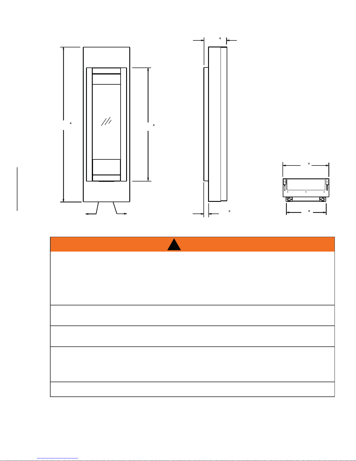
2.1 DIMENSIONS
11
49
/
16
36
9
7
/
16
3
/
8
15
ELECTRICAL
ACCESS
GAS LINE
ACCESS
2.2 GENERAL INSTRUCTIONS
CARBON MONOXIDE POISONING MAY LEAD TO DEATH
EARLY SIGNS OF CARBON MONOXIDE POISONING RESEMBLE THE FLU, WITH HEADACHE, DIZZI-
NESS AND/OR NAUSEA. IF YOU HAVE THESE SIGNS, THE HEATER MAY NOT BE WORKING PROP-
ERLY. GET FRESH AIR AT ONCE! HAVE HEATER SERVICED.
SOME PEOPLE---PREGNANT WOMEN, PERSONS WITH HEART OR LUNG DISEASE, ANEMIA, THOSE
UNDER THE INFLUENCE OF ALCOHOL, THOSE AT HIGH ALTITUDES--- ARE MORE AFFECTED BY
CARBON MONOXIDE THAN OTHERS.
THE HEATER IS ONLY FOR USE WITH THE TYPE OF GAS INDICATED ON THE RATING PLATE. THIS
HEATER IS NOT CONVERTIBLE FOR USE WITH OTHER GASES.
OBJECTS PLACED IN FRONT OF THE HEATER SHOULD BE KEPT A MINIMUM OF 48” AWAY FROM
THE GLASS FRONT FACES OF THE HEATER.
USE ONLY WOLF STEEL APPROVED OPTIONAL ACCESSORIES AND REPLACEMENT PARTS WITH
THIS APPLIANCE. USING NON-LISTED ACCESSORIES AND REPLACEMENT PARTS (BLOWERS,
LOUVRES, TRIMS, GAS COMPONENTS, VENT COMPONENTS, ETC.) COULD RESULT IN A SAFETY
HAZARD AND WILL VOID THE LIMITED LIFETIME WARRANTY.
!
WARNING
1
/
2
1
13
DO NOT OPERATE WITHOUT CERAMIC CATALYST IN PLACE.
W415-0847 / A / 06.08.10
6
This gas appliance should be installed and serviced by a qualifi ed installer to conform with local codes.
Installation practices vary from region to region and it is important to know the specifi cs that apply to your
area, for example: in Massachusetts State:
• The appliance off valve must be a “T” handle gas cock.
• The fl exible connector must not be longer than 36“.
• The appliance is not approved for installation in a bedroom or bathroom unless the appliance is a direct
vent sealed combustion product.
• A carbon monoxide detector is required in all rooms containing gas fi red appliances.
• WARNING: This product must be installed by a licensed plumber or gas fi tter when installed within the
commonwealth of Massachusetts.
• Un-vented room appliance shall be installed in accordance with 527 CMR 30.00 and 248 CMR 3.00
through 7.00.
• Sellers of un-vented propane or natural gas-fi red space / room appliances shall provide to each purchaser
a copy of 527 CMR 30.00 upon the sale of the appliance from http://www.napoleonfi replaces.com/
Webshare/installation_manuals/mass_requirements.pdf
In absence of local codes, install the appliance to the current National Fuel Gas Code, ANSI Z223.1
Installation Code which can be obtained from:
American National Standards Institute Inc. or National Fire Protection Association Inc.
1430 Broadway Batterymarch Park
New York, NY 10018 Quincy, MA 02269
The appliance and its individual shutoff valve must be disconnected from the gas supply piping system during
any pressure testing of that system at test pressures in excess of 1/2 psig (3.5 kPa). The appliance must be
isolated from the gas supply piping system by closing its individual manual shutoff valve during any pressure
testing of the gas supply piping system at test pressures equal to or less than 1/2 psig (3.5 kPa). When
installed with a blower the junction box must be electrically connected and grounded in accordance with local
codes. In the absence of local codes, use the current ANSI / NFPA 70 National Electric Code. In the case
where the blower is equipped with a power cord it must be connected into a properly grounded receptacle.
The grounding prong must not be removed from the cord plug.
We suggest that our gas
As long as the required clearance to combustibles is maintained,
the most desirable and benefi cial location for the appliance is in the
center of a building, thereby allowing the most effi cient use of the
heat created. The location of windows, doors and the traffi c fl ow in
the room where the appliance is to be located should be considered.
www.ncertied.org
hearth products be installed
and serviced by professionals
who are certied in the U.S.
by the National Fireplace
Institute
Specialists
®
(NFI) as NFI Gas
If the appliance is installed directly on carpeting, vinyl tile or other
combustible material other than wood fl ooring, the appliance shall be installed on a metal or wood panel
extending the full width and depth. NOTE: This does not apply to stoves.
4.6
W415-0847 / A / 06.08.10
2.3 GENERAL INFORMATION
FOR USE WITH THE TYP
SE WITH OTHER GASE
E COMBUSTION A
COLUM
MANIFOLD
P
NIMUM
SU
MAXIMUM
SUP
0-200
6,
GVFT
E
APPLIANCE, WHICH WILL C
OPER INSTALLATION
RY OR LOSS OF LIFE. REFER
MATERIALS
0
(PROPA
ECI T15
CONTROL
99
OXY PR
FOR YOUR SATISFACTION, THIS APPLIANCE HAS BEEN TEST-FIRED TO ENSURE ITS OPERATION
AND QUALITY!
Altitude 0 - 2,000* 0 - 2,000*
Maximum input 6,000 6,000
Minimum Inlet Gas Supply Pressure 4.5” Water Column 11” Water Column
Maximum Inlet Gas Supply Pressure 7” Water Column 13” Water Column
Manifold Pressure Under Flow Conditions 3.5” Water Column 10” Water Column
* When the appliance is installed at elevations above 2,000ft and in the absence of specifi c recommendations
from the local authority having jurisdiction, the certifi ed altitude input rating shall be reduced at the rate of 4%
for each additional 1,000ft.
This appliance is only for use with the type of gas indicated on the rating plate. For rating plate location,
see either “INSTALLATION OVERVIEW” or “RATING PLATE INFORMATION” section. This appliance is not
convertible for use with other gases, unless a certifi ed kit is used.
Expansion / contraction noises during heating up and cooling down cycles are normal and are to be expected.
7
RA TES AND EFFICIENCIES
NATURAL GAS PROPANE
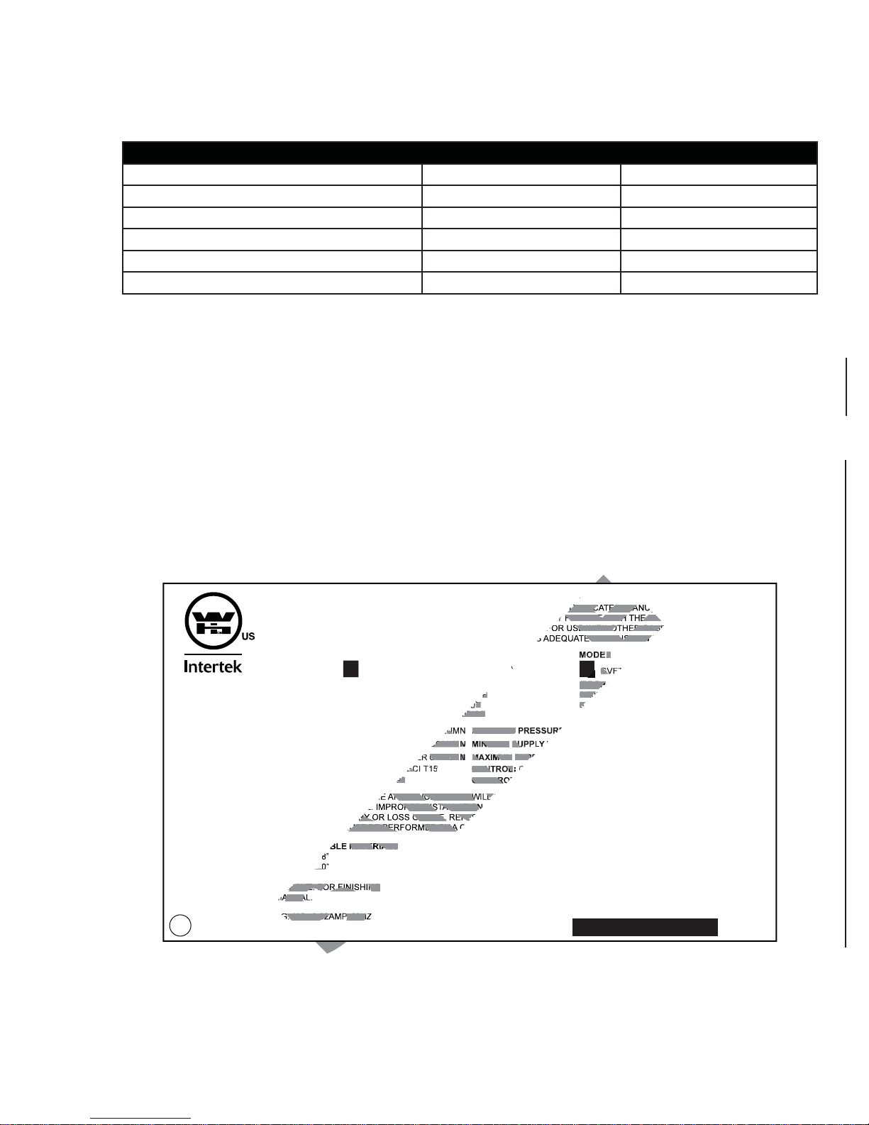
2.4 RATING PLATE INFORMATION
The rating label is located under the control panel and is chained to the appliance. DO NOT REMOVE.
This illustration is for reference only. Refer to the rating plate on the appliance for accurate information.
CERTIFIED UNDER : ANSI Z21.11.2a-2008 VOLUME II, UNVENTED ROOM HEATER
THIS APPLIANCE MAY BE INSTALLED IN AN AFTERMARKET, PERMANENTLY LOCATED, MANUFACTURED (MOBILE) HOME,
WHERE NOT PROHIBITED BY LOCAL CODES. THIS APPLIANCE IS ONLY FOR USE WITH THE TYPE OF GAS INDICATED ON
THE RATING PLATE. THIS APPLIANCE IS NOT FIELD CONVERTIBLE FOR USE WITH OTHER GASES.
THIS IS A GAS-FIRED UNVENTED ROOM HEATER THAT REQUIRES ADEQUATE COMBUSTION AND VENTILATION AIR.
MODEL
GVFT8N
REFERENCE #16437
WARNING: DO NOT ADD ANY MATERIAL TO THE APPLIANCE, WHICH WILL COME IN CONTACT WITH THE FLAME. DO NOT USE ACCESSORIES
NOT APPROVED FOR USE WITH THIS APPLIANCE. IMPROPER INSTALLATION, ADJUSTMENT, ALTERATION, SERVICE OR MAINTAINANCE CAN
CAUSE PROPERTY DAMAGE, PERSONAL INJURY OR LOSS OF LIFE. REFER TO THE OWNER’S INFORMATION MANUAL PROVIDED WITH THIS
APPLIANCE. INSTALLATION AND SERVICE MUST BE PERFORMED BY A QUALIFIED INSTALLER, SERVICE AGENCY OR THE GAS SUPPLIER.
MINIMUM CLEARANCES TO COMBUSTIBLE MATERIALS
TOP 18” FLOOR 8”
SIDES 1” BACK 0”
TOP, SIDES & BACK AS PER ABOVE. FOR FINISHING
MATERIAL, SEE OWNERS MANUAL.
ELECTRICAL RATING: 115v 0.82AMP, 60HZ
(NATURAL GAS) (PROPANE)
0-2000FT (0-1370m)
6,000 BTU/h
#56
MANIFOLD PRESSURE: 3.5" WA TER COLUMN
MINIMUM SUPPLY PRESSURE: 4.5" WA TER COLUMN
MAXIMUM SUPPL Y PRESSURE: 7.0" WA TER COLUMN
OXY PROTECTOR SIT:
CONTROL:
COPRECI T15
#9099
CERTIFIED FOR USA
ALTITUDE
INPUT
ORIFICE
MANIFOLD PRESSURE: 10" WA TER COLUMN
MINIMUM SUPPLY PRESSURE: 1 1" WATER COLUMN
MAXIMUM SUPPLY PRESSURE: 13" WA TER COLUMN
CONTROL:
OXY PROTECTOR SIT:
SERIAL NUMBER:
COPRECI T15
MODEL
GVFT8P
0-2000FT (0-1370m)
6,000 BTU/h
#69
#9266
MADE IN CANADA
WOLF STEEL L TD, BARRIE, ON, CANADA
GVFT8
W385-0480 / A
W415-0847 / A / 06.08.10

8
A
3.0 INSTALLATION
3.1 COMBUSTION AND VENTILATION AIR PROVISIONS
This appliance shall not be installed in a confi ned space or unusually tight construction unless provisions are
provided for adequate combustion and ventilation air.
The National Fuel Gas Code, ANSI Z223.1 / NFPA 54 defi nes a confi ned space as a space whose volume is
less than 50 cubic feet per 1,000 Btu per hour (4.8 m3 per kw) of the aggregate input rating of all appliances
installed in that space and an unconfi ned space as a space whose volume is not less than 50 cubic feet per
1,000 Btu per hour (4.8 m3 per kw) of the aggregate input rating of all appliances installed in that space.
Rooms communicating directly with the space in which the appliances are installed, through openings not
furnished with doors are considered a part of the unconfi ned space.
The GVFT8 is rated at 6,000 BTUs per hour for natural gas and propane and therefore requires a minimum
unconfi ned space of 300 cubic feet.
3.2 DETERMINING CONFINED OR UNCONFINED SPACE
This appliance shall not be installed in a room or space unless the required volume of indoor combustion air
is provided by the method described in the National Fuel Gas Code, ANSI Z223.1 / NFPA 54, the International
Fuel Gas Code, or applicable local codes.
17.1A
To determine the volume of the room where the appliance is to be installed, multiply the width x the length x
the ceiling height of that room measured in feet. If any adjoining rooms are connected by grilles or openings
such as kitchen pass-throughs, etc., the volume of those rooms may be added to the total.
Multiply the room volume by 1000 and divide this amount by 50 to determine the maximum BTU/hr that the
space can support with adequate combustion and ventilation air.
dd the Btu/hr of all fuel burning appliances located within the space such as gas furnace, gas water
appliance, etc. Do not include direct vent gas appliances which draw their input and output air from and to the
outdoors.
!
WARNING
IF THE AREA IN WHICH THE APPLIANCE MAY BE OPERATED IS SMALLER THAN THAT DEFINED AS
AN UNCONFINED SP ACE OR IF THE BUILDING IS OF UNUSUALLY TIGHT CONSTRUCTION, PROVIDE
ADEQUA TE COMBUSTION AND VENTILATION AIR BY ONE OF THE METHODS DESCRIBED IN THE
NA TIONAL FUEL GAS CODE ANSI Z223.1/ NFPA 54 , AIR FOR COMBUSTION AND VENTILATION, OR THE
APPLICABLE LOCAL CODE.
IF THE AREA IN WHICH THE APPLIANCE MAY BE OPERATED DOES NOT MEET THE REQUIRED VOLUME
FOR INDOOR COMBUSTION AIR, COMBUSTION AND VENTILATION AIR SHALL BE PROVIDED BY ONE
OF THE METHODS DESCRIBED IN THE ANSI Z223.1 / NFPA 54, THE INTERNATIONAL FUEL GAS CODE,
OR APPLICABLE LOCAL CODES.
Unusually tight construction is defi ned as construction where:
A) Walls and ceilings exposed to the outside atmosphere have a continuous water vapour retarder with a
rating of 1 perm (6 x 10-11 kg per pa-sec-m2) or less with openings gasketed or sealed, and
B) Weather stripping has been added on openable windows and doors, and
C) Caulking or sealants are applied to areas such as joints around window and door frames, between sole
plates and fl oors, between wall-ceiling joints, between wall panels, at penetrations for plumbing, electrical,
and gas lines, and at other openings.
W415-0847 / A / 06.08.10
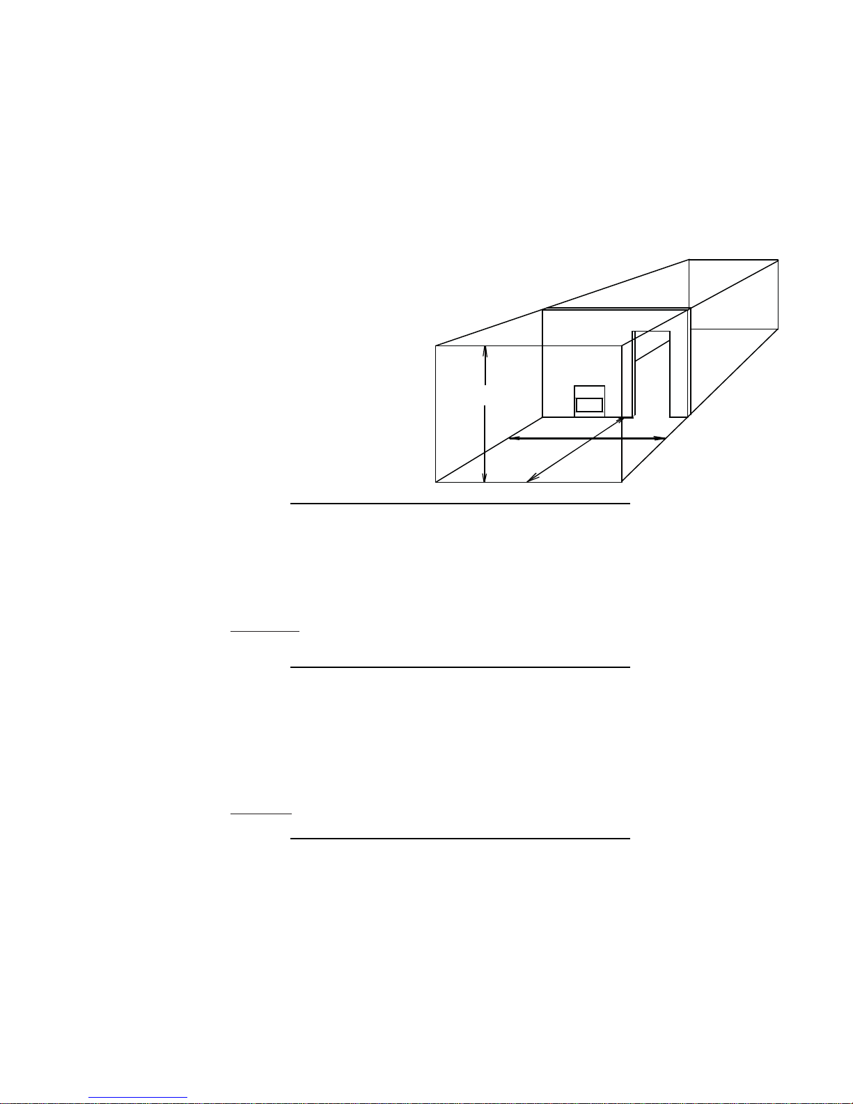
A
n unvented room appliance is recommended for use as a secondary heat source rather than as a primary
LENGTH
HEIGHT
ROOM 2
ROOM 1
WIDTH
source. Gas combustion produces water vapour which could occur at the rate of approximately one ounce of
water for every 1,000 BTU/hr of gas input. During the cold weather season, indoor humidity levels tend to be
low. Consequently, this water vapour can enhance the living space. However if a problem should occur:
A) Ensure suffi cient combustion and circulation air
B) Use a dehumidifi er
C) Do not use the unvented room appliance as a primary heat source
Without suffi cient fresh air for proper operation, poor fuel combustion can result. Carbon Monoxide is a result
of poor combustion.
If additional fresh air is required, use one of the methods described in the National Fuel
Gas Code, ANSI Z223.1, Section 5.3 or the applicable local code.
Room Volume = Length x Width x Height
Max BTU/hr = Room Volume x 1000 / 50
If for example:
The length of the rooms is 10 feet,
The width of Room 1 is 10 feet,
The width of Room 2 is 15 feet,
The height of the rooms is 8 feet.
9
The volume of Room 1: 10x10x8 = 800 cubic feet
The volume of Room 2: 10x15x8 = 1200 cubic feet
19.1A
EXAMPLE 1:
In this example, because there is no door to the adjoining room, the volume of the adjoining room may be
added to the volume of the room with the heater to get a total unconfi ned space.
The total unconfi ned space: 800 + 1200 = 2000 cubic feet.
Maximum BTU/h: 2000x1000 = 40,000 BTU/h
50
19.2
If there are no more fuel burning appliances within this space then the 6,000 BTU/h input of the appliance is
suitable to be installed. This also assumes that the construction of this space is not unusually tight.
EXAMPLE 2:
If in this example a solid door separates Room 1 from Room 2, the volume of Room 2 could not be used. In
this case the maximum BTU/h would be:
Maximum BTU/h: 800x1000 = 16,000 BTU/h
50
19.3
If there are no more fuel burning appliances within this space then the 6,000 BTU/h input of the appliance is
suitable to be installed. This also assumes that the construction of this space is not unusually tight.
W415-0847 / A / 06.08.10

10
3.3 GAS INSTALLATION
RISK OF FIRE, EXPLOSION OR ASPHYXIATION. ENSURE THERE ARE NO IGNITION SOURCES SUCH AS
SUPPORT GAS CONTROL WHEN ATTACHING GAS SUPPLY PIPE TO PREVENT DAMAGING GAS LINE.
ALWAYS LIGHT THE PILOT WHETHER FOR THE FIRST TIME OR IF THE GAS SUPPLY HAS RUN OUT
WITH THE GLASS DOOR OPENED OR REMOVED. PURGING OF THE GAS SUPPLY LINE SHOULD BE
PERFORMED BY A QUALIFIED SERVICE TECHNICIAN. ASSURE THAT A CONTINUOUS GAS FLOW IS AT
THE BURNER BEFORE CLOSING THE DOOR. ENSURE ADEQUATE VENTILATION. FOR GAS AND
ELECTRICAL LOCATIONS, SEE “DIMENSION” SECTION.
ALL GAS CONNECTIONS MUST BE CONTAINED WITHIN THE APPLIANCE WHEN COMPLETE.
HIGH PRESSURE WILL DAMAGE VALVE. DISCONNECT GAS SUPPLY PIPING BEFORE TESTING GAS
VALVE SETTINGS HAVE BEEN FACTORY SET, DO NOT CHANGE.
Installation and servicing to be done by a qualifi ed installer. Do not use open fl ame.
3.3.1
• Move the appliance into position and secure.
!
WARNING
SPARKS OR OPEN FLAMES.
LINE AT TEST PRESSURES ABOVE 1/2 PSIG.
3.3.2
• If equipped with a fl ex connector the appliance is designed to accept a 1/2” gas supply. Without the
connector it is designed to accept a 3/8” gas supply. The appliance is equipped with a manual shut off
valve to turn off the gas supply to the appliance.
3.3.3
• Connect the gas supply in accordance to local codes. In the absence of local codes, install to the
current CAN/CSA-B149.1 Installation Code in Canada or to the current National Fuel Gas Code, ANSI
Z223.1 / NFPA 54 in the United States.
3.3.4
• When fl exing any gas line, support the gas valve so that the lines are not bent or kinked.
3.3.5
• The gas line fl ex-connector should provide suffi cient movement to permit shifting the burner assembly
on it’s side.
3.3.6
• Check for gas leaks by brushing on a soap and water solution.
30.1A
WARNING:
This appliance must not be recessed. For alcove
clearances refer to installation instructions.
ADVERTENCIA:
Este dispositivo no debe empotrarse. Para obtener
las medidas de la cavidad, consulte las
instrucciones sobre la instalación.
W385-0479
W385-0479
FLEX
CONNECTOR
W415-0847 / A / 06.08.10
SHUT OFF
VALVE

3.4 GAS PRESSURE
Outlet pressure can be checked to ensure it is measuring 3.5” W.C. (NG)
or 10.0” W.C. (LP).
3.4.1 Outlet pressure can be checked by removing cap (A) using a
3/16 Allen key and replacing it with a 1/8 NPT barb fi tting.
3.4.2 Place pressure gauge tube over the fi tting.
11
1/8
NPT BARB
FITTING
A
3.4.3 Once completed, be sure to replace the cap (A).
PRESSURE
GAUGE
3.5
10
NATURAL
GAS
PROPANE
GAS
W415-0847 / A / 06.08.10

12
4.0 FRAMING
4.1 CLEARANCE TO COMBUSTIBLES
THIS APPLIANCE MUST BE INSTALLED IN THE CABINET PROVIDED. THE CABINET IS DESIGNED
TO BE INSTALLED ON FINISHED SURFACES.
THIS APPLIANCE CAN BE RECESSED INTO AN ALCOVE A MAXIMUM OF 12” PROVIDED THAT
ALL CLEARANCES ARE MAINTAINED.
THE CABINET MAY BE INSTALLED DIRECTLY ONTO A COMBUSTIBLE SURFACE.
MINIMUM CLEARANCES TO COMBUSTIBLES:
- 18” to top
- 1” to sides
- 8” to bottom
- 0” to rear (cabinet)
- 1/2” to rear (appliance)
!
WARNING
12” MAX.
TYPICAL
INSTALLATION
(OUTSIDE WALL)
18”
MIN.
8”
MIN.
ALCOVE
INSTALLATION
(INSIDE WALL)
18” MIN.
8’
8” MIN.
W415-0847 / A / 06.08.10
1” MIN.
12” MAX.
1” MIN.

5.0 FINISHING
5.1 MOUNTING CABINET INSTALLATION
!
WARNING
DEFLECTOR MUST BE INSTALLED.
13
5.1.1 Using the installation template (W122-0401) sup-
plied, determine the best mounting location for
your new Torch, see “DIMENSIONS” or “MINIMUM
CLEARANCE TO COMBUSTIBLES” section. Mark
all 14 hole centres on the wall (surface) using the
template.
5.1.2 Align the holes on the defl ector with the holes on
the back of the torch as illustrated. Secure with the
appropriate fasteners.
5.1.3 Remove the template. Depending on the surface
and fasteners, drill the appropriate holes. Hold the
Torch up, aligning the mounting brackets to the
mounting holes. Secure the Torch to the wall using
the appropriate fasteners.
NOTE: The Torch has been designed to have a
1/2” clearance between the rear outer panel and
the mounting surface.
5.1.4 Start the fasteners into each of the six remaining
mounting holes. Align the keyholes of the frame
to the heads of the fasteners and slide the frame
down onto the fasteners. Ensure the frame is
plumb and level before tightening the fasteners.
NOTE: It is recommended that the gas and elec-
trical be connected to the appliance at this stage. Both must enter the appliance at the opening created
between the bottom of the Torch and the bottom of the mounting frame.
5.1.5 Slide the front of the cabinet over the mounting frame, ensuring the “mesh” is to the top. Start each of the four
screws (supplied) through the slots. Once the cabinet has been adjusted for
depth the four screws can be
tightened.
1
DEFLECTOR
CABINET
INSTALLATION
TEMPLATE
TORCH
MOUNTING
FRAME
3
2
4
MOUNTING
BRACKET
KEYHOLE
W415-0847 / A / 06.08.10

14
5.2 DOOR REMOVAL
GLASS MAY BE HOT, DO NOT TOUCH GLASS UNTIL COOLED.
THE DOOR LATCHES ARE PART OF A SAFETY SYSTEM AND MUST BE PROPERLY ENGAGED. DO
NOT OPERATE THE APPLIANCE WITH LATCHES DISENGAGED.
FACING AND/OR FINISHING MATERIALS MUST NOT INTERFERE WITH AIR FLOW THROUGH AIR
OPENINGS, LOUVRES OPENINGS, OPERATION OF LOUVRES OR DOORS OR ACCESS FOR
SERVICE. OBSERVE ALL CLEARANCES WHEN APPLYING COMBUSTIBLE MATERIALS.
BEFORE DOOR IS REMOVED TURN THE APPLIANCE OFF AND WAIT UNTIL APPLIANCE IS COOL TO
THE TOUCH. DOORS ARE HEAVY AND FRAGILE SO HANDLE WITH CARE.
!
WARNING
75.1
The door is held in place at the bottom by a retainer
tab that inserts into a slot in the bottom edge of the
door, and at the top with a tab that secures in the
same fashion. The door is removed by lifting it off the
tabs. When replacing, guide the door over the upper
tab fi rst, then over the lower tab.
SECURING THE DOOR IN PLACE
When shipped, the door is secured with two hitch pins
along the top edge, replacing them is optional.
To secure the door in place use the supplied hitch pins
as illustrated.
HITCH PIN
E
G
N
A
L
F
R
O
O
D
P
O
T
E
T
R
A
R
O
O
D
M
O
T
T
O
B
I
N
E
R
W415-0847 / A / 06.08.10

5.3 FRAME INSTALLATION
5.3.1 Align the two holes in the
upper portion of the hinge
on the control door to those
in the bottom trim bracket,
secure using two of the #8
x 1/2” hex head screws
supplied.
5.3.2 Install the top trim bracket to
the fi rebox using the three
#9 - 14 x 1/2” hex head
screws supplied in the
5.3.3 Rest the top lip of the frame on the top trim bracket, and
the securing tabs at the bottom of the frame on the bottom
trim bracket.
5.3.4 Align the two slots in the top of the frame with the two holes
in the top trim bracket and secure using the two #10 pan head screws
supplied however do not fully tighten to leave room for adjustment.
5.3.5 Align the holes in the securing tabs at the bottom of the
frame with the holes in the bottom trim bracket and secure using the
two remaining #8 x 1/2” hex head screws, however do not fully tighten
to leave room for adjustment.
CONTROL DOOR
manual baggie.
W385-0479
BOTTOM
TRIM
BRACKET
BRACKET
FRAME
TOP
TRIM
15
W
385-
0
479
5.3.6 If required, the bottom trim bracket can be adjusted by loosening it’s securing
screws.
5.3.7 Once the frame is perfectly square and the control door will close without
rubbing against the sides of the frame, tighten all screws.
5.3.8 Open the control door.
5.3.9 Insert the door stop chain into the receiving slot in the control door.
5.3.10 Insert the door stop chain into the receiving slot in the frame so that when
fully open the control door has a clear-
ance of 1/8” to the fi nished wall. NOTE:
In most cases, a count of 9 balls
between receiving slots will give the
desired clearance.
DOOR
STOP
CHAIN
5.3.11 Close the control door.
The frame has been designed to accommodate fi nished material thicknesses of .500” - .750”.
If it is necessary to pull the frame out to the
max. .750” the magnetic catch will need to be adjusted.
Minor adjustment can be made by removing shims
from behind the magnet. Major adjustments can be made
by moving the magnet to the outside of the panel.
RECEIVING
SLOTS
BOTTOM
TRIM
BRACKET
W385-0479
Adjustment may be required to accommodate the door stop chain slack when the control door is closed. The control door
securing screws can be loosened to allow adjustment. Before re-tightening the screws ensure the control door is still recessed into the frame at a similar offset to the top trim piece.
W415-0847 / A / 06.08.10

16
5.4 LOGO PLACEMENT
With the control door closed, affi x the logo to the front face of the
control door at the bottom left corner.
5.5 GLASS MEDIA INSTALLATION
CLEAN THE GLASS MEDIA PRIOR TO INSTALLATION. BEFORE APPLYING THE CLEANED GLASS, ENSURE
!
WARNING
THAT IT IS DRY.
1/4”
(APPROX.)
LOGO
1/4”
CONTROL
DOOR
(APPROX.)
DO NOT CHANGE OR SUBSTITUTE THE GLASS MEDIA MATERIAL PROVIDED WITH THIS APPLIANCE. IF
REPLACING, USE ONLY THE REPLACEMENT GLASS MEDIA AVAILABLE FROM YOUR AUTHORIZED
DEALER / DISTRIBUTOR.
Evenly spread the glass media onto the media tray, ensuring no glass media falls onto the burner. If this happens, insert a clean bag into your vacuum cleaner and vacuum out the glass media. Replacement glass can
be purchased from your local authorized dealer / distributor.
CLEANING GLASS MEDIA
Glass media may have a fi ne oil residue that needs to be cleaned prior to installation. Clean the glass with mild
dish soap, drain, rinse thoroughly and dry before placing around the burner.
CLEANING CRYSTALS
To help maintain the luster and beauty of these crystals over time, carefully polish them by using a soft, lintfree cloth. If they become heavily soiled, you may use a mild detergent and wash them individually by hand, as
you would a fi ne chandelier. Please avoid rubbing the crystals together. Do not use a dishwasher.
74.2
GLASS
BURNER
MEDIA
MEDIA
TRAY
W415-0847 / A / 06.08.10

5.6 LK8 LIGHT INSTALLATION (OPTIONAL)
5.6.1 Turn off the electrical and gas supply to the appliance.
5.6.2 Remove the frame from the appliance by removing the 2 stain-
less steel hex head securing screws from the bottom and lifting the
frame off of the top trim bracket.
5.6.3 Lay the frame down on its front, being careful not to scratch the fi n-
ish.
5.6.4 Starting at the top of the frame, take one light assembly and care-
fully snap it into place in the hole provided. Repeat for each of the
light assemblies. The wires on the top 2 light assemblies will need
to be fed in behind the heat shields.
NOTE: When installing the light kit be careful not to scratch
your fi ngers on any of the exposed screws in the frame.
5.6.5 Connect the light assemblies to the appropriate fl ags on the wire
harness. The wire harness is labeled (TR) top right, (BR) bottom
right (TL) Top left and (BL) bottom left.
5.6.6 Secure the wires into the clips at both sides and the bottom of the
frame. Use the extra clips provided to retain any loose wires.
TL
BL
17
TR
BR
CLIPS X 5
5.6.7 Re-attach frame onto appliance.
5.6.8 Open the control panel door, leave the wires connected to the ON/
OFF switch and place the transformer into the bottom of the appli-
ance. Plug the transformer into the receptacle.
5.6.9 Attach one of the wire leads from the transformer to the lead on
the wire harness labeled “TRANS”, and the other to the ON/OFF
switch. Attach the last lead on the wire harness labeled “SWI” to
the ON/OFF switch.
5.6.10 Close the control panel door.
5.6.11 Turn on the gas supply and electrical power.
SWI
TRANS
W415-0847 / A / 06.08.10

18
6.0 ELECTRICAL INFORMATION
!
WARNING
DO NOT USE THIS APPLIANCE IF ANY PART HAS BEEN UNDER WATER. CALL A QUALIFIED SER-
VICE TECHNICIAN IMMEDIATELY TO HAVE THE APPLIANCE INSPECTED FOR DAMAGE TO THE
ELECTRICAL CIRCUIT.
RISK OF ELECTRICAL SHOCK OR EXPLOSION. DO NOT WIRE 110V TO THE VALVE OR TO THE
APPLIANCE WALL SWITCH. INCORRECT WIRING WILL DAMAGE CONTROLS.
ALL WIRING SHOULD BE DONE BY A QUALIFIED ELECTRICIAN AND SHALL BE IN COMPLIANCE
WITH LOCAL CODES. IN THE ABSENCE OF LOCAL CODES, USE THE CURRENT CSA C22.1
CANADIAN ELECTRIC CODE IN CANADA OR THE CURRENT NATIONAL ELECTRIC CODE
ANSI/NFPA NO. 70 IN THE UNITED STATES.
It is not necessary to hard wire this appliance, however if accessories that do require power are being considered it is recommended to make your electrical connection during initial installation.
As illustrated, route a grounded 2-wire, 60HZ power cable to the junction box. At this point it must be strain
relieved and insulated.
10.1
ELECTRICAL
BOX COVER
(C/W 2 RECEPTACLES)
CABLE
CONNECTOR
GROUND
L1
SCREW
GROUND
L2
W415-0847 / A / 06.08.10
WIRE NUTS
ELECTRICAL BOX
(C/W GROUND SCREW)

7.0 OPERATION
IF YOU DO NOT FOLLOW THESE INSTRUCTIONS EXACTLY, A FIRE OR EXPLOSION MAY RESULT
CAUSING PROPERTY DAMAGE, PERSONAL INJURY OR LOSS OF LIFE.
ALWAYS LIGHT THE PILOT WHETHER FOR THE FIRST TIME OR IF THE GAS SUPPLY HAS RUN OUT WITH
If appliance shuts off, do not relight until you provide fresh air. If appliance keeps shutting off, have it
serviced. Keep burner and control compartment clean.
When lit for the fi rst time, the appliance will emit a slight odour for a few hours. This is a normal temporary
condition caused by the “burn-in” of internal paints and lubricants used in the manufacturing process and will
not occur again. After extended periods of non-operation such as following a vacation or a warm weather season, the appliance may emit a slight odour for a few hours. This is caused by dust particles burning off. In both
cases, open a window to suffi ciently ventilate the room.
A. This appliance is equipped with a pilot which must be lit by hand while following these instructions exactly.
B. Before operating smell all around the appliance area for gas and next to the fl oor because some gas
is heavier than air and will settle on the fl oor.
C. Use only your fi nger to push in the gas control. Never use tools. If the control will not push in, do not try
to repair it. Call a qualifi ed service technician. Force or attempted repair may result in a fi re or explosion.
D. Do not use this appliance if any part has been under water. Immediately call a qualifi ed service techni-
cian to inspect the appliance and replace any part of the control system and any gas control which
has been under water.
● Do not try to light any appliance.
● Do not touch any electric switch; do not use any phone in your building.
● Immediately call your gas supplier from a neighbour’s phone. Follow the
gas supplier’s instructions.
● If you cannot reach your gas supplier, call the fi re department.
!
WARNING
THE GLASS DOOR OPENED OR REMOVED.
FOR YOUR SAFETY READ BEFORE LIGHTING:
WHAT TO DO IF YOU SMELL GAS:
PILOT
19
THERMOCOUPLE
OXY PROTECTOR
LIGHTING INSTRUCTIONS:
1. STOP! Read the safety information located above.
2. Turn off all electric power to the fi replace.
3. Open the control door.
4. Wait fi ve (5) minutes to clear out any gas. If you smell
gas including near the fl oor, STOP! Follow “B” in the
above safety information on this label. If you don’t smell
gas go to the next step.
5. Find pilot located behind the burner.
6. Ensure the on/off switch is in the on position.
7. Depress and hold gas control while lighting the pilot with the push button ignitor. Keep control fully
depressed for one minute, then release. If pilot does not continue to burn repeat steps 3 through 7.
8. Releasing the gas control will also ignite the main burner.
9. Turn on all electric power to the appliance if service is to be performed.
GAS
CONTROL
TO TURN OFF GAS:
1. Turn off all electrical power to the appliance if service is to be performed.
2. Push the on/off switch to the off position.
47.15
W415-0847 / A / 06.08.10

20
A
8.0 ADJUSTMENTS
8.1 VENTURI ADJUSTMENT
This model has an air shutter that has been factory set open according to the chart below:
Closing the air shutter will cause a more yellow fl ame, but can lead to carboning.
Opening the air shutter will cause a more blue fl ame, but can cause fl ame lifting
from the burner ports. The fl ame may not appear yellow immediately; allow 15
to 30 minutes for the fi nal fl ame color to be established.
IR SHUTTER ADJUSTMENT MUST ONLY BE DONE BY A QUALIFIED
INSTALLER!
NOTE: It is important that the venturi sits down tight on the orifi ce.
AIR SHUTTER OPENINGS
LP 3/16” DIA
NG 1/16” DIA
VENTURI
BURNER
AIR
SHUTTER
OPENING
49.3
8.2 FLAME CHARACTERISTICS
It is important to periodically perform a visual check of the burner fl ame. Compare them
to the illustration provided.
W415-0847 / A / 06.08.10

9.0 MAINTENANCE
TURN OFF THE GAS AND ELECTRICAL POWER BEFORE SERVICING THE APPLIANCE.
CAUTION: Label all wires prior to disconnection when servicing controls. Wiring errors can cause improper
and dangerous operation. Verify proper operation after servicing. This appliance should be inspected before
use and at least annually by a qualifi ed service person. The appliance area must be kept clear and free of
combustible materials, gasoline or other fl ammable vapours and liquids. The fl ow of combustion and ventilation
air must not be obstructed.
9.0.1 Keep the control compartment, burner, and air shutter opening clean by vacuuming or brushing, at
least once a year.
9.0.2 Check to see that the main burner ignites when the switch for the burner is turned on. A 5 second light-
up period is satisfactory. If ignition takes longer, consult your authorized dealer.
9.0.3 Check that the gasketing on the sides and top of the door are not broken or missing. Replace if necessary.
9.1 CLEANING
• Visually inspect the appliance for carbon buildup.
• Using a small whisk or brush, brush off the excess carbon and vacuum up or sweep into the garbage.
• Check the appliance for corrosion of the main burner base.
21
This procedure must be performed by a
qualified service person!
Inspect the pilot for any visible
contamination or debris (usually lint, pet
hair, spider webs, carpet fibre, etc.) and
remove.
Disconnect the pilot from the pilot tubing
line, using a 1/2” wrench. Blow out the
housing in the same direction as the gas
flow. Re-install the pilot tube, turn on the
gas and check for leaks.
If this does not improve the performance, replace the Oxy Protector with
an exact replacement. The device is
tamper resistant with no field serviceable parts.
CORRECT PILOT FLAME
(Clean, stable, pronounced
blue flame).
INCORRECT PILOT FLAME
(Flame lifts upwards,
becomes unstable with more
of an orange tip).
HOUSING
46.2
W415-0847 / A / 06.08.10

22
9.2 CARE OF GLASS
DO NOT CLEAN GLASS WHEN HOT! DO NOT USE
ABRASIVE CLEANERS TO CLEAN GLASS.
Buff lightly with a clean dry soft cloth. Clean both sides
of the glass after the fi rst 10 hours of operation with a
recommended fi replace glass cleaner. Thereafter clean
as required. If the glass is not kept clean permanent
discoloration and / or blemishes may result.
9.3 DOOR GLASS REPLACEMENT
DO NOT USE SUBSTITUTE MATERIALS.
GLASS MAY BE HOT, DO NOT TOUCH GLASS UNTIL COOLED.
CARE MUST BE TAKEN WHEN REMOVING AND DISPOSING OF ANY BROKEN DOOR GLASS OR
DAMAGED COMPONENTS. BE SURE TO VACUUM UP ANY BROKEN GLASS FROM INSIDE THE
APPLIANCE BEFORE OPERATION.
DO NOT STRIKE, SLAM OR SCRATCH GLASS. DO NOT OPERATE APPLIANCE WITH GLASS
REMOVED, CRACKED, BROKEN OR SCRATCHED.
!
WARNING
!
WARNING
HOT GLASS WILL
CAUSE BURNS.
DO NOT TOUCH GLASS
UNTIL COOLED.
NEVER ALLOW CHILDREN
TO TOUCH GLASS.
5.1
Having removed the door, lay on a smooth fl at surface, face down.
There are 4 glass retainers that need to be bent away from the
glass to release it from the frame. Do not pry on the glass.
When replacing DO NOT SUBSTITUTE MA TERIAL, replace the
gasket (W562-0008) and the glass (W300-0110). Set new glass
into the frame and gently bend tabs into the gasket to secure.
* Ensure that the gasketed end of the glass is placed into the
top of the door frame.
NOTE: Care must be taken when removing and disposing
of any broken glass or damaged components. Be sure to
vacuum up any broken glass from inside the appliance
before operation.
GASKET*
GLASS
TOP
GLASS
RETAINERS
W415-0847 / A / 06.08.10

10.0 REPLACEMENTS
Contact your dealer or the factory for questions concerning prices and policies on replacement parts. Normally
all parts can be ordered through your Authorized dealer / distributor.
FOR WARRANTY REPLACEMENT PARTS, A PHOTOCOPY OF THE ORIGINAL INVOICE WILL BE
REQUIRED TO HONOUR THE CLAIM.
When ordering replacement parts always give the following information:
• Model & Serial Number of appliance
• Installation date of appliance
• Part number
• Description of part
• Finish
* IDENTIFIES ITEMS WHICH ARE NOT ILLUSTRATED. FOR
FURTHER INFORMA TION, CONTACT YOUR AUTHORIZED DEALER.
REF PART NO. DESCRIPTION
1 W225-0251 DOOR FRAME
2 W562-0008 DOOR GASKET
3 W010-1959 GLASS C/W GASKET
4 * W300-0132 GLASS
5 W100-0104 BURNER
6 W200-0263 IGNITOR COVER
7 W200-0262 BURNER COVER
8* W725-0060 NATURAL GAS VALVE - 3.5” W.C.
9 W137-0001 CERAMIC CATALYST
10 W662-0006 OXY PROTECTOR - NG
10 W662-0007 OXY PROTECTOR - LP
11 W530-0028 REGULATOR - NG
11 W530-0029 REGULATOR - LP
12* W455-0085 #56 NATURAL GAS ORIFICE
12* W455-0086 #69 PROPANE GAS ORIFICE
13 W475-0590 BACK PANEL
14* W300-0108 ACCESS GLASS (BLACK)
15* W385-0334 NAPOLEON LOGO
16* W562-0046 ROPE GASKET, BACK PANEL
17* W385-0479 CONTROL PANEL LABEL
18 W200-0300 CONTROL PANEL
19 W660-0088 ROCKER SWITCH - ON/OFF
20 W660-0082 ROCKER SWITCH - LIGHTS
COMPONENTS
23
!
WARNING
FAILURE TO POSITION THE PARTS
IN ACCORDANCE WITH THIS
MANUAL OR FAILURE TO USE ONLY
PARTS SPECIFICALLY APPROVED
WITH THIS APPLIANCE MAY
RESULT IN PROPERTY DAMAGE OR
PERSONAL INJURY.
41.1
2
1
3
Items not shown to scale.
5
10
7
6
11
9
19
13
18
20
W415-0847 / A / 06.08.10

24
ACCESSORIES
REF PART NO. DESCRIPTION
21 TMCSS MOUNTING CABINET
22 TFSSO FRAME KIT
23* LK8 LIGHT KIT
21
22
W415-0847 / A / 06.08.10

11.0 TROUBLE SHOOTING
!
WARNING
ALWAYS LIGHT THE PILOT WHETHER FOR THE FIRST TIME OR IF THE GAS SUPPLY HAS RAN OUT,
WITH THE GLASS DOOR OPEN OR REMOVED.
TURN OFF THE GAS AND ELECTRICAL POWER BEFORE SERVICING THE APPLIANCE.
APPLIANCE MAY BE HOT, DO NOT SERVICE UNTIL APPLIANCE HAS COOLED.
DO NOT USE ABRASIVE CLEANERS.
SYMPTOM PROBLEM TEST SOLUTION
Flame length
consistently too
large or too small.
Carboning occurs.
Carbon is being
deposited on glass,
and combustion
chamber surfaces.
White / grey fi lm forms. Sulphur from fuel is being
No gas to the main
burner; switch is on.
Burner will not light,
ignitor sparks.
Unit is over-fi red or under-
fi red.
Air shutter has become
blocked.
Flame is impinging on the
combustion chamber.
deposited on glass,
logs, rocks, media or
combustion chamber
surfaces.
Switch is defective. - Connect a jumper wire across the wall switch
Burner orifi ce is blocked. - Remove stoppage in orifi ce.
Control valve faulty. - Replace.
Faulty valve. - Replace.
No gas at the burner. - Check that the manual valve is turned on.
Out of propane gas. - Fill the tank.
25
- Check pressure readings.
- Outlet pressure can be checked by removing
cap (A) and replacing it with a 1/8” NPT barb
fi tting. Next, place pressure gauge tubing over
the fi tting. Gauge should read 3.5” W.C. for
natural gas or 10.0” W.C. for propane. AFTER
TAKING PRESSURE READINGS, BE SURE
TO REPLACE CAP TO RESEAL. DO NOT
OVER-TORQUE.
- Leak test with a soap and water solution.
- Ensure air shutter opening is free of lint or other
obstructions.
- Open air shutter to increase the primary air.
- Check the input rate: check the manifold
pressure and orifi ce size as specifi ed by the
rating plate values.
- Clean the glass with a gas appliance glass
cleaner. DO NOT CLEAN GLASS WHEN HOT.
If deposits are not cleaned off regularly, the
glass may become permanently marked.
terminals; if main burner lights, replace switch.
- Replace the valve.
42.11
W415-0847 / A / 06.08.10

26
12.0 WARRANTY
NAPOLEON® products are manufactured under the strict Standard of the world recognized ISO 9001 : 2008
NAPOLEON® products are designed with superior components and materials assembled by trained
craftsmen who take great pride in their work. The burner and valve assembly are leak and test-fi red at a
quality test station. The complete heater is again thoroughly inspected by a qualifi ed technician before
packaging to ensure that you, the customer, receives the quality product that you expect from NAPOLEON®.
NAPOLEON® GAS FIREPLACE PRESIDENT’S LIFETIME LIMITED WARRANTY
The following materials and workmanship in your new NAPOLEON® gas heater are warranted against
defects for as long as you own the heater. This covers: combustion chamber, heat exchanger, stainless
steel burner, phazer™ logs and embers, rocks, ceramic glass (thermal breakage only), gold plated parts
against tarnishing, porcelainized enameled components and aluminum extrusion trims.*
Electrical (110V and millivolt) components and wearable parts such as blowers, gas valves, thermal switch,
switches, wiring, remote controls, ignitor, gasketing, and pilot assembly are covered and NAPOLEON® will
provide replacement parts free of charge during the fi rst year of the limited warranty.*
Labour related to warranty repair is covered free of charge during the fi rst year. Repair work, however,
requires the prior approval of an authorized company offi cial. Labour costs to the account of NAPOLEON®
are based on a predetermined rate schedule and any repair work must be done through an authorized
NAPOLEON® dealer.
* Construction of models vary. Warranty applies only to components included with your specifi c heater.
Quality Assurance Certifi cate.
CONDITIONS AND LIMITATIONS
NAPOLEON® warrants its products against manufacturing defects to the original purchaser only. Registering your warranty is not
necessary. Simply provide your proof of purchase along with the model and serial number to make a warranty claim. NAPOLEON®
reserves the right to have its representative inspect any product or part thereof prior to honouring any warranty claim. Provided that the
purchase was made through an authorized NAPOLEON® dealer your heater is subject to the following conditions and limitations:
This factory warranty is non-transferable and may not be extended whatsoever by any of our representatives.
The gas heater must be installed by a licensed, authorized service technician or contractor. Installation must be done in accordance
with the installation instructions included with the product and all local and national building and fi re codes. This limited warranty does
not cover damages caused by misuse, lack of maintenance, accident, alterations, abuse or neglect and parts installed from other
manufacturers will nullify this warranty.
This limited warranty further does not cover any scratches, dents, corrosion or discoloring caused by excessive heat, abrasive and
chemical cleaners nor chipping on porcelain enamel parts, mechanical breakage of PHAZER™ logs and embers.
NAPOLEON® warrants its stainless steel burners against defects in workmanship and material for life, subject to the following
conditions: During the fi rst 10 years NAPOLEON® will replace or repair the defective parts at our option free of charge. From 10 years
to life, NAPOLEON® will provide replacement burners at 50% of the current retail price.
In the fi rst year only, this warranty extends to the repair or replacement of warranted parts which are defective in material or
workmanship provided that the product has been operated in accordance with the operation instructions and under normal conditions.
After the fi rst year, with respect to this President’s Lifetime Limited Warranty, NAPOLEON® may, at its discretion, fully discharge all
obligations with respect to this warranty by refunding to the original warranted purchaser the wholesale price of any warranted but
defective part(s).
NAPOLEON® will not be responsible for installation, labour or any other expenses related to the reinstallation of a warranted part and
such expenses are not covered by this warranty.
Notwithstanding any provisions contained in the President’s Lifetime Limited Warranty, NAPOLEON’S responsibility under this
warranty is defi ned as above and it shall not in any event extend to any incidental, consequential or indirect damages.
This warranty defi nes the obligations and liability of NAPOLEON® with respect to the NAPOLEON® gas heater and any other
warranties expressed or implied with respect to this product, its components or accessories are excluded.
NAPOLEON® neither assumes, nor authorizes any third party to assume, on its behalf, any other liabilities with respect to the sale of
this product.
NAPOLEON® will not be responsible for: over-fi ring, downdrafts, spillage caused by environmental conditions such as rooftops,
buildings, nearby trees, hills, mountains, inadequate vents or ventilation, excessive venting confi gurations, insuffi cient makeup air, or
negative air pressures which may or may not be caused by mechanical systems such as exhaust fans, furnaces, clothes dryers, etc.
Any damages to heater, combustion chamber, heat exchanger, brass trim or other components due to water, weather damage, long
periods of dampness, condensation, damaging chemicals or cleaners will not be the responsibility of NAPOLEON®.
ALL SPECIFICATIONS AND DESIGNS ARE SUBJECT TO CHANGE WITHOUT PRIOR NOTICE DUE TO ON-GOING PRODUCT
IMPROVEMENTS. NAPOLEON® IS A REGISTERED TRADEMARK OF WOLF STEEL LTD. PATENTS U.S. 5.303.693.801 - CAN.
2.073.411, 2.082.915. © WOLF STEEL LTD.
2.1
W415-0847 / A / 06.08.10

13.0 SERVICE HISTORY
27
43.1
W415-0847 / A / 06.08.10

28
14.0 NOTES
W415-0847 / A / 06.08.10
44.1
 Loading...