

Napoleon StarFire GD70PT-S Installation And Operation Instructions Manual
INSTALLER: THESE INSTRUCTIONS MUST BE CONVEYED TO AND REMAIN WITH THE HOMEOWNER.
CERTIFIED UNDER CANADIAN AND AMERICAN NATIONAL STANDARDS, CSA 2.33, ANSI Z21.88 FOR VENTED GAS FIREPLACE HEATERS
VENTED GAS FIREPLACE HEATER
DIRECT VENT MILLIVOLT SYSTEM
1
INSTALLATION AND OPERATION INSTRUCTIONS FOR:
NATURAL GAS MODEL
PROPANE GAS MODEL
CERTIFIED FOR CANADA AND UNITED STATES USING ANSI / CSA METHODS
GD70NT-S
GD70PT-S
WARNING: If the information in these instructions is not followed exactly, a fire or
explosion may result causing property damage, personal injury or death.
FOR YOUR SAFETY
Do not store or use gasoline or other flammable vapours and liquids in the vicinity of
this or any other appliance.
WHAT TO DO IF YOU SMELL GAS:
• Do not try to light any appliance.
• Do not touch any electrical switch.
• Do not use any phone in your building.
• Immediately call your gas supplier from a
neighbor's phone. Follow the gas supplier's
instructions.
• If you cannot reach your gas supplier, call
the fire department.
Installation and service must be performed by a qualified installer, service agency
or the gas supplier.
Wolf Steel Ltd., 24 Napoleon Rd., Barrie, ON L4M 4Y8 Canada • (705)721-1212 • fax(705)722-6031
www.napoleonfireplaces.com • ask@napoleon.on.ca
W415-0434 / C / 03.24.05

2
TABLE of CONTENTS
PG2-5 INTRODUCTION
Warranty
Dimensions
General Instructions
General Information
Care of Glass & Plated Parts
5-10 VENTING
Vent lengths
Venting Specifications
Air Terminal Locations
11-15 INSTALLATION/FRAMING
Wall & Ceiling Protection
Using Flexible Vent Components
Fireplace Vent Connection
Using Rigid Vent Components
Restricting Vertical Vents
Gas Installation
Mobile Home Installation
Framing
Mantle Clearances and Enclosures
16-19 FINISHING
Door Installation
Door Opening and Closing
Louvre Installation
Log Shipping Bracket Removal
Decorative Panels
Charcoal Strips
Log Placement
Baffle Installation
Charcoal Embers
Accent Lite Replacement
20 BLOWER INSTALLATION
THERMODISC REPLACEMENT
21-22 OPERATION / MAINTENANCE
Operating Instructions
Maintenance
22 ADJUSTMENTS
Pilot Burner Adjustment
Venturi Adjustment
23-24 REPLACEMENTS
Ordering Replacement Parts
Replacement Parts
Terminal Kits
Vent Kits
Accessories
25-26 TROUBLE SHOOTING GUIDE
27 SERVICE HISTORY
PLEASE RETAIN THIS MANUAL FOR FUTURE REFERENCE
WARNING
• Do not burn wood or other materials in this fireplace.
• Adults and especially children should be alerted to the hazards of high surface temperatures and should stay away
to avoid burns or clothing ignition. Supervise young children when they are in the same room as the fireplace.
• Due to high temperatures, the fireplace should be located out of traffic and away from furniture and draperies.
• Clothing or other flammable material should not be placed on or near the fireplace.
• Any safety screen or guard removed for servicing must be replaced prior to operating the fireplace.
• It is imperative that the control compartments, burners and circulating blower and its passageway in the fireplace
and venting system are kept clean. The fireplace and its venting system should be inspected before use and at
least annually by a qualified service person. More frequent cleaning may be required due to excessive lint from
carpeting, bedding material, etc. The fireplace area must be kept clear and free from combustible materials,
gasoline and other flammable vapours and liquids.
• Under no circumstances should this fireplace be modified.
• This fireplace must not be connected to a chimney flue pipe serving a separate solid fuel burning appliance.
• Do not use this fireplace if any part has been under water. Immediately call a qualified service technician to inspect
the fireplace and to replace any part of the control system and any gas control which has been under water.
• Do not operate the fireplace with the glass door removed, cracked or broken. Replacement of the glass should be
done by a licensed or qualified service person.
• Do not strike or slam shut the fireplace glass door.
• This fireplace uses and requires a fast acting thermocouple. Replace only with a fast acting thermocouple supplied by Wolf Steel Ltd.
NOTE: Changes, other than editorial, are denoted by a vertical line in the margin.
W415-0434 / C / 03.24.05

NAPOLEON gas fireplaces are manufactured under the strict Standard of the world recognized
ISO 9001 : 2000 Quality Assurance Certificate.
NAPOLEON products are designed with superior components and materials, assembled by trained craftsmen
who take great pride in their work. The burner and valve assembly are leak and test-fired at a quality test
station. The complete fireplace is thoroughly inspected by a qualified technician before packaging to ensure that
you, the customer, receives the quality product that you expect from NAPOLEON.
NAPOLEON GAS FIREPLACE PRESIDENT'S LIFETIME LIMITED WARRANTY
The following materials and workmanship in your new napoleon gas fireplace are warranted against defects for as
long as you own the fireplace. This covers: combustion chamber, heat exchanger, stainless steel burner, PHAZER™
logs and embers, ceramic glass (thermal breakage only), gold plated parts against tarnishing, porcelainized enamelled
components and aluminum extrusion trims.
Electrical (110V and millivolt) components and wearable parts such as the blower, gas valve, thermal switch, switches,
wiring, remote control, ignitor, gasketing, and pilot assembly are covered and NAPOLEON will provide replacement
parts free of charge during the first year of the limited warranty. Light bulbs are not covered by this warranty.
Labour related to warranty repair is covered free of charge during the first year. Repair work, however, requires the
prior approval of an authorized company official. Labour costs to the account of NAPOLEON are based on a predetermined rate schedule and any repair work must be done through an authorized NAPOLEON dealer.
3
CONDITIONS AND LIMITATIONS
NAPOLEON warrants its products against manufacturing defects to the original purchaser only -- i.e., the individual or legal entity (registered
customer) whose name appears on the warranty registration card filed with NAPOLEON -- provided that the purchase was made through an authorized
NAPOLEON dealer and is subject to the following conditions and limitations:
This factory warranty is nontransferable and may not be extended whatsoever by any of our representatives.
The gas fireplace must be installed by a licenced, authorized service technician or contractor. Installation must be done in accordance with the
installation instructions included with the product and all local and national building and fire codes.
This limited warranty does not cover damages caused by misuse, lack of maintenance, accident, alterations, abuse or neglect and parts installed
from other manufacturers will nullify this warranty.
This limited warranty further does not cover any scratches, dents, corrosion or discolouring caused by excessive heat, abrasive and chemical
cleaners nor chipping on porcelain enamel parts, mechanical breakage of PHAZER™ logs and embers, nor any venting components used in the
installation of the fireplace.
NAPOLEON warrants its stainless steel burners against defects in workmanship and material for life, subject to the following conditions: During
the first 10 years NAPOLEON will replace or repair the defective parts at our option free of charge. From 10 years to life, NAPOLEON will provide
replacement burners at 50% of the current retail price.
In the first year only, this warranty extends to the repair or replacement of warranted parts which are defective in material or workmanship provided
that the product has been operated in accordance with the operation instructions and under normal conditions.
After the first year, with respect to this President's Limited Lifetime Warranty, NAPOLEON may, at its discretion, fully discharge all obligations
with respect to this warranty by refunding to the original warranted purchaser the wholesale price of any warranted but defective part(s).
After the first year, NAPOLEON will not be responsible for installation, labour or any other costs or expenses related to the reinstallation of a
warranted part, and such expenses are not covered by this warranty.
Notwithstanding any provisions contained in this President's Limited Lifetime Warranty, NAPOLEON’S responsibility under this warranty is defined
as above and it shall not in any event extend to any incidental, consequential or indirect damages.
This warranty defines the obligations and liability of NAPOLEON with respect to the NAPOLEON gas fireplace and any other warranties expressed
or implied with respect to this product, its components or accessories are excluded.
NAPOLEON neither assumes, nor authorizes any third party to assume, on its behalf, any other liabilities with respect to the sale of this product.
NAPOLEON will not be responsible for: over-firing, downdrafts, spillage caused by environmental conditions such as rooftops, buildings, nearby
trees, hills, mountains, inadequate vents or ventilation, excessive venting configurations, insufficient makeup air, or negative air pressures which
may or may not be caused by mechanical systems such as exhaust fans, furnaces, clothes dryers, etc.
Any damages to fireplace, combustion chamber, heat exchanger, brass trim or other component due to water, weather damage, long periods of
dampness, condensation, damaging chemicals or cleaners will not be the responsibility of NAPOLEON.
The bill of sale or copy will be required together with a serial number and a model number when making any warranty claims from your authorized
dealer. The warranty registration card must be returned within fourteen days to register the warranty.
NAPOLEON reserves the right to have its representative inspect any product or part thereof prior to honouring any warranty claim.
ALL SPECIFICATIONS AND DESIGNS ARE SUBJECT TO CHANGE WITHOUT PRIOR NOTICE DUE TO ON-GOING PRODUCT IMPROVEMENTS. NAPOLEON® IS A REGISTERED
TRADEMARK OF WOLF STEEL LTD. PATENTS U.S. 5.303.693.801 - CAN. 2.073.411, 2.082.915. © WOLF STEEL LTD.
W415-0434 / C / 03.24.05
4
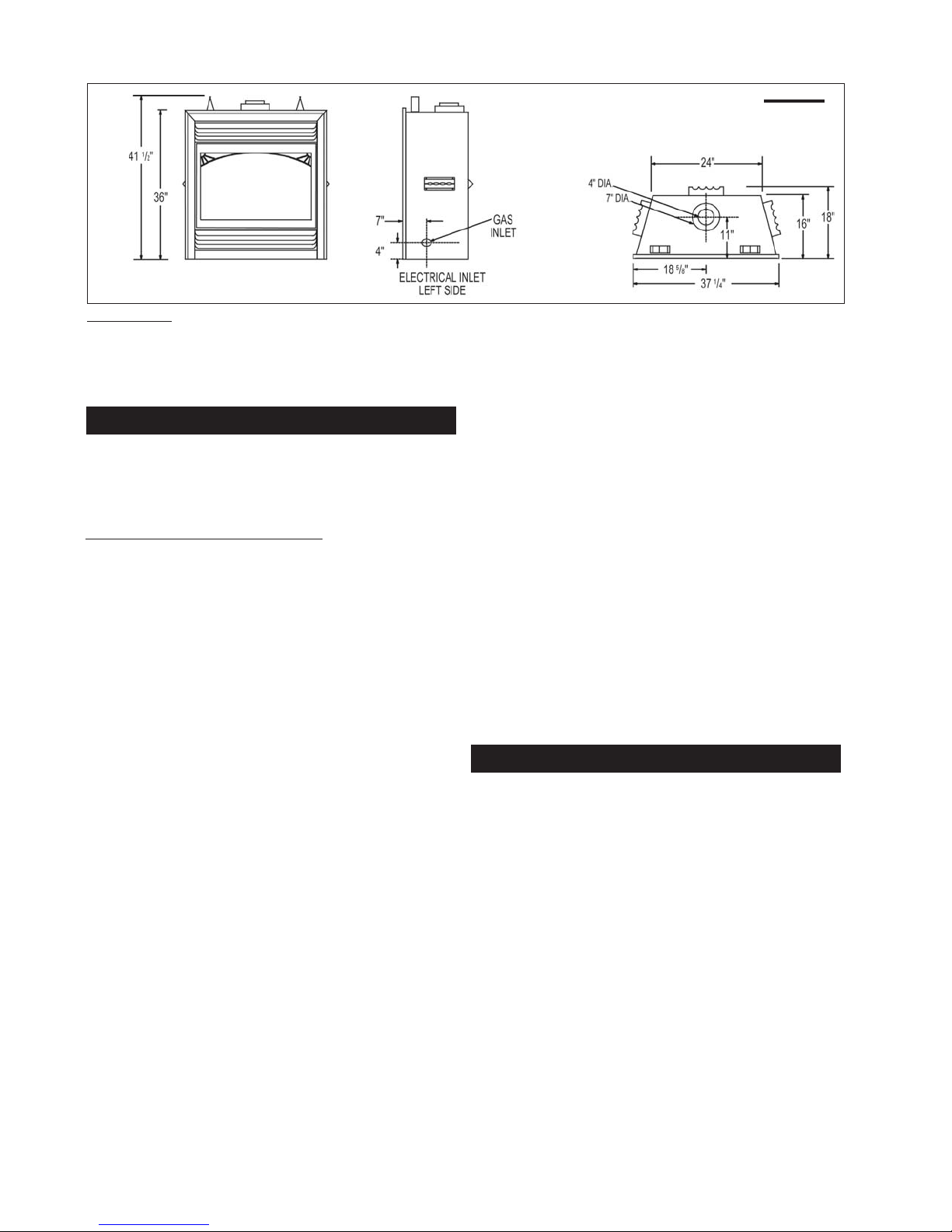
FIGURE 1
WARNING: The door for this fireplace is sold
separately. The door must be installed and
closed before operation begins. Refer to
"DOOR INSTALLATION" under the "FINISH-
ING" Section for details.
GENERAL INSTRUCTIONS
THIS GAS FIREPLACE SHOULD BE INSTALLED AND
SERVICED BY A QUALIFIED INSTALLER to conform with
local codes. Installation practices vary from region to region and it is important to know the specifics that apply to
your area,
for example: in Massachusetts State:
• The fireplace damper must be removed or welded in the
open position prior to installation of a fireplace insert or
gas log.
• The appliance off valve must be a “T” handle gas cock.
• The flexible connector must not be longer than 36 inches.
• The appliance is not approved for installation in a
bedroom or bathroom unless the unit is a direct vent
sealed combustion product.
• WARNING: This product must be installed by a licensed
plumber or gas fitter when installed within the
commonwealth of Massachusetts.
In absence of local codes, install to the current CAN/CGA B149 Installation Code in Canada or to the National Fuel
Gas Code, ANSI Z223.1, and NFPA 54 in the United States.
Suitable for mobile home installation if installed in accordance with the current standard CAN/CSA Z240MH Series,
for gas equipped mobile homes, in Canada or ANSI Z223.1
and NFPA 54 in the United States.
The fireplace and its individual shutoff valve must be disconnected from the gas supply piping system during any pressure
testing of that system at test pressures in excess of 1/2 psig
(3.5 kPa). The fireplace must be isolated from the gas supply
piping system by closing its individual manual shutoff valve
during any pressure testing of the gas supply piping system at
test pressures equal to or less than 1/2 psig (3.5 kPa).
When the fireplace is installed directly on carpeting, vinyl tile or
other combustible material other than wood flooring, the fireplace shall be installed on a metal or wood panel extending
the full width and depth.
The optional heat circulating blower is supplied with a cord. If
installed, the junction box must be electrically connected and
grounded in accordance with local codes. In the absence of
local codes, use the current CSA C22.1 CANADIAN ELECTRICAL CODE in Canada or the ANSI/NFPA 70 NATIONAL ELECTRICAL CODE in the United States.
W415-0434 / C / 03.24.05
Purge all gas lines with the glass door of the fireplace open .
Assure that a continuous gas flow is at the burner before
closing the door.
Under extreme vent configurations, allow several minutes
(5-15) for the flame to stabilize after ignition.
Eight (8") inches is the minimum bend radius allowed for
the 7" diameter flexible air liner.
Provide adequate ventilation and combustion air. Provide
adequate accessibility clearance for servicing and operating the fireplace. Never obstruct the front opening of the
fireplace.
Objects placed in front of the fireplace must be kept a
minimum of 48" from the front face of the unit.
Minimum clearance to combustible construction
from fireplace and vent surfaces:
fireplace framing - 0" to stand-offs (top, rear and sides)
fireplace finishing - 3" to sides, 7¼" to top of unit
vent pipe - 2 inches *
recessed depth - 16 inches
* The first 2 feet of outer 7 inch diameter vent pipe from
the appliance must be wrapped in the 1" thick insulation
sleeve (supplied). There must be a 1inch air gap in addi-
See FSee F
igurigur
tion to the insulation sleeve.
See F
See FSee F
igur
igurigur
e 34.e 34.
e 34.
e 34.e 34.
GENERAL INFORMATION
FOR YOUR SATISFACTION, THIS FIREPLACE HAS BEEN
TEST-FIRED TO ASSURE ITS OPERATION AND QUALITY!
Maximum input is 35,000 BTU/hr for natural gas and 33,000
BTU/hr for propane. When the fireplace is installed at elevations above 4,500ft, and in the absense of specific recommendations from the local authority having jurisdiction, the
certified high altitude input rating shall be reduced at the rate
of 4% for each additional 1,000ft. Maximum output for natural
gas is 28,350 BTU/hr at an efficiency of 81%; and 26,400 BTU/
hr for propane at an efficiency of 80%. Minimum A.F.U.E. rating
is 64% for natural gas and 65% for propane. Minimum inlet
gas supply pressure is 4.5 inches water column for natural
gas and 11 inches water column for propane. Maximum inlet
gas pressure is 7 inches water column for natural gas and 13
inches water column for propane. Manifold pressure under
flow conditions is 3.5 inches water column for natural gas
and 10 inches water column for propane.
This fireplace is approved for bathroom, bedroom and bedsitting room installations and is suitable for mobile home
installation. The natural gas model can only be installed in
a mobile home that is permanently positioned on its site
and fueled with natural gas.
5
This fireplace may This fireplace may
This fireplace may
This fireplace may This fireplace may
nently located, manufactured (mobile) home, where notnently located, manufactured (mobile) home, where not
nently located, manufactured (mobile) home, where not
nently located, manufactured (mobile) home, where notnently located, manufactured (mobile) home, where not
prpr
ohibited bohibited b
pr
ohibited b
prpr
ohibited bohibited b
This fireplace is only for use with the type of gas indicatedThis fireplace is only for use with the type of gas indicated
This fireplace is only for use with the type of gas indicated
This fireplace is only for use with the type of gas indicatedThis fireplace is only for use with the type of gas indicated
on the ron the r
on the r
on the ron the r
with other gases, unless a certified kit is used.with other gases, unless a certified kit is used.
with other gases, unless a certified kit is used.
with other gases, unless a certified kit is used.with other gases, unless a certified kit is used.
No external electricity (110 volts or 24 volts) is required forNo external electricity (110 volts or 24 volts) is required for
No external electricity (110 volts or 24 volts) is required for
No external electricity (110 volts or 24 volts) is required forNo external electricity (110 volts or 24 volts) is required for
the gas system operation.the gas system operation.
the gas system operation.
the gas system operation.the gas system operation.
y local codesy local codes
y local codes
y local codesy local codes
aa
ting plating pla
a
ting pla
aa
ting plating pla
be installed in an aftermarket perma-be installed in an aftermarket perma-
be installed in an aftermarket perma-
be installed in an aftermarket perma-be installed in an aftermarket perma-
..
.
..
tete
. T. T
his fhis f
irir
ee
te
. T
tete
. T. T
place is not conplace is not con
his f
ir
e
place is not con
his fhis f
irir
ee
place is not conplace is not con
vv
erer
tibtib
v
er
tib
vv
erer
tibtib
le fle f
le f
le fle f
or useor use
or use
or useor use
Expansion / contraction noises during heating up and cooling down cycles are normal and are to be expected. Change
in flame appearance from "HI" to "LO" is more evident in
natural gas than in propane.
VENTING
VENTING LENGTHS & AIR TERMINAL LOCATIONS
Use only Wolf Steel, Simpson Dura-Vent, Selkirk Direct
Temp or American Metal Amerivent venting components.
Minimum and maximum vent lengths, for both horizontal
and vertical installations, and air terminal locations for either system are set out in this manual and must be adhered to. For Simpson Dura-Vent,
and American Metal Amerivent, follow the installation
procedure provided with the venting components.
For vent systems that provide seals on the inner exhaust
flue, only the outer air intake joints must be sealed using a
red high temperature silicone (RTV). This same sealant
maybe used on both the inner exhaust and outer intake
vent pipe joints of all other approved vent systems except
for the exhaust vent pipe connection to the fireplace flue
collar which must be sealed using the black high temperature sealant Mill Pac. High temperature sealant must
be ordered separately.
When using Napoleon venting components, use only approved Wolf Steel Ltd. rigid / flexible vent components with
the following termination kits: WALL TERMINAL KIT GD222,
or 1/12 TO 7/12 PITCH ROOF TERMINAL KIT GD110, 8/12
TO 12/12 ROOF TERMINAL KIT GD111, FLAT ROOF TER-
MINAL KIT GD112 or PERISCOPE KIT GD201 (for wall pen-
etration below grade). With flexible venting, in conjunction
with the various terminations, use either the 5 foot vent kit
GD220 or the 10 foot vent kit GD330. These vent kits allow
for either horizontal or vertical venting of the fireplace. FIG-
URES 2, 3, & 5.
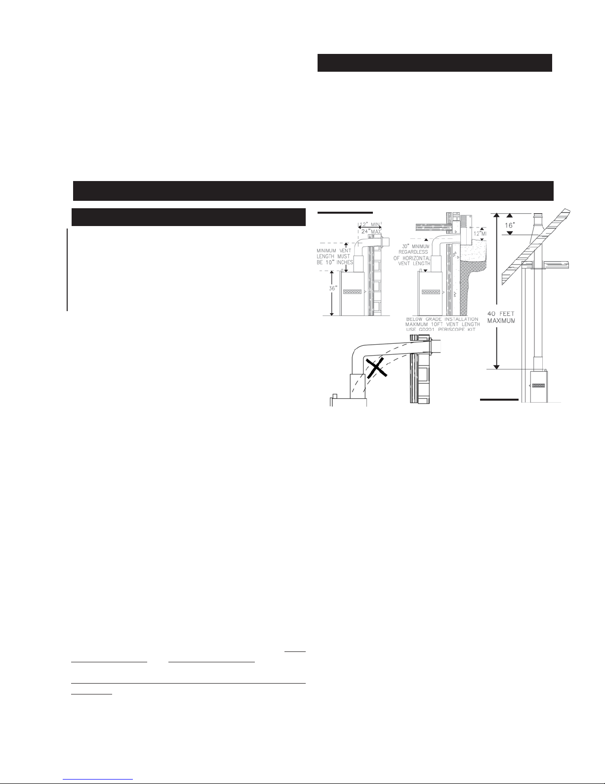
The maximum allowable vertical vent length is 40 feet.
The maximum number of allowable 4" vent connections is
three horizontally or vertically (excluding the fireplace and
the air terminal connections) when using aluminum flexible venting.
For optimum flame appearance and fireplace performance,
keep the vent length and number of elbows to a minimum.
The air terminal must remain unobstructed at all times.
Examine the air terminal at least once a year to verify that it
is unobstructed and undamaged.
When venting, the horizontal run must be kept to a minimum of 12 inches
or a maximum of 20 feet. If a 20 foot
horizontal run is required, the fireplace must have a
minimum vertical rise immediately off the fireplace of
57 inches.
FIGURES FIGURES
FIGURES
FIGURES FIGURES
2a-c2a-c
..
2a-c
. When terminating vertically,
2a-c2a-c
..
the vertical rise is a minimum 34 inches and a maximum
40 feet above the fireplace.
Horizontal runs may have a 0 inch rise per foot in all
cases using SIMPSON DURA-VENT or NAPOLEON
RIGID OR FLEXIBLE venting components when venting as illustrated in Figures 2a, 2b, and 2c.
Selkirk Direct Temp
FIGURE 3.FIGURE 3.
FIGURE 3.
FIGURE 3.FIGURE 3.
CARE OF GLASS, AND PLATED PARTS
Do not use abrasive cleaners to clean plated parts. Buff
lightly with a clean dry cloth. The glass is 3/16" ceramic
glass available from your Napoleon / Wolf Steel Ltd. dealer.
DO NOT SUBSTITUTE MATERIALS. Clean the glass after
the first 10 hours of operation with a recommended gas
fireplace glass cleaner. Thereafter clean as required. DO
NOT CLEAN GLASS WHEN HOT! If the glass is not kept
clean permanent discolouration and / or blemishes may
result.
FIGURES 2a-c
FIGURE 3
For optimum performance, it is recommended that allFor optimum performance, it is recommended that all
For optimum performance, it is recommended that all
For optimum performance, it is recommended that allFor optimum performance, it is recommended that all
horizontal runs have a minimum ¼ inch rise per foot.horizontal runs have a minimum ¼ inch rise per foot.
horizontal runs have a minimum ¼ inch rise per foot.
horizontal runs have a minimum ¼ inch rise per foot.horizontal runs have a minimum ¼ inch rise per foot.
Wolf Steel rigid and flexible venting systems must not
be combined.
Wolf Steel, Simpson Dura-Vent, Selkirk Direct Temp and
American Metal Amerivent venting systems must not
be combined.
Provide a means for visually checking the vent connec-Provide a means for visually checking the vent connec-
Provide a means for visually checking the vent connec-
Provide a means for visually checking the vent connec-Provide a means for visually checking the vent connection to the fireplace after the fireplace is installed.tion to the fireplace after the fireplace is installed.
tion to the fireplace after the fireplace is installed.
tion to the fireplace after the fireplace is installed.tion to the fireplace after the fireplace is installed.
Do not allow the inside liner to bunch up on horizontal orDo not allow the inside liner to bunch up on horizontal or
Do not allow the inside liner to bunch up on horizontal or
Do not allow the inside liner to bunch up on horizontal orDo not allow the inside liner to bunch up on horizontal or
vv
erer
tical rtical r
v
er
vv
erer
gap between the inner and outer liner all around is re-gap between the inner and outer liner all around is re-
gap between the inner and outer liner all around is re-
gap between the inner and outer liner all around is re-gap between the inner and outer liner all around is required for safe operation.quired for safe operation.
quired for safe operation.
quired for safe operation.quired for safe operation.
VV
ent lengths thaent lengths tha
V
ent lengths tha
VV
ent lengths thaent lengths tha
tics, garages, crawl space) should be wrapped with atics, garages, crawl space) should be wrapped with a
tics, garages, crawl space) should be wrapped with a
tics, garages, crawl space) should be wrapped with atics, garages, crawl space) should be wrapped with a
protective insulation sleeve to minimize condensation.protective insulation sleeve to minimize condensation.
protective insulation sleeve to minimize condensation.
protective insulation sleeve to minimize condensation.protective insulation sleeve to minimize condensation.
Use a firestop when penetrating interior walls, floor orUse a firestop when penetrating interior walls, floor or
Use a firestop when penetrating interior walls, floor or
Use a firestop when penetrating interior walls, floor orUse a firestop when penetrating interior walls, floor or
ceiling.ceiling.
ceiling.
ceiling.ceiling.
In order to avoid the possibility of exposed insulation orIn order to avoid the possibility of exposed insulation or
In order to avoid the possibility of exposed insulation or
In order to avoid the possibility of exposed insulation orIn order to avoid the possibility of exposed insulation or
vv
aa
v
a
vv
aa
it is recommended that the walls of the fireplace enclo-it is recommended that the walls of the fireplace enclo-
it is recommended that the walls of the fireplace enclo-
it is recommended that the walls of the fireplace enclo-it is recommended that the walls of the fireplace enclosursur
sur
sursur
other outside wother outside w
other outside w
other outside wother outside w
clearance to combustibles is maintained within the cav-clearance to combustibles is maintained within the cav-
clearance to combustibles is maintained within the cav-
clearance to combustibles is maintained within the cav-clearance to combustibles is maintained within the cavityity
ity
ityity
For safe and proper operation of the fireplace followFor safe and proper operation of the fireplace follow
For safe and proper operation of the fireplace follow
For safe and proper operation of the fireplace followFor safe and proper operation of the fireplace follow
the vthe v
the v
the vthe v
Deviation from the minimum vertical vent length can cre-Deviation from the minimum vertical vent length can cre-
Deviation from the minimum vertical vent length can cre-
Deviation from the minimum vertical vent length can cre-Deviation from the minimum vertical vent length can create difficulty in burner start-up and/or carboning.ate difficulty in burner start-up and/or carboning.
ate difficulty in burner start-up and/or carboning.
ate difficulty in burner start-up and/or carboning.ate difficulty in burner start-up and/or carboning.
uns and elbowsuns and elbows
tical r
uns and elbows
tical rtical r
uns and elbowsuns and elbows
pour barpour bar
pour bar
pour barpour bar
e be 'fe be 'f
inished', (i.einished', (i.e
e be 'f
inished', (i.e
e be 'fe be 'f
inished', (i.einished', (i.e
..
.
..
enting instrenting instr
enting instr
enting instrenting instr
t pass thrt pass thr
t pass thr
t pass thrt pass thr
rier coming in contact with the frier coming in contact with the f
rier coming in contact with the f
rier coming in contact with the frier coming in contact with the f
all ofall of
all of
all ofall of
uction euction e
uction e
uction euction e
. K. K
eeee
. K
ee
. K. K
eeee
ough unheaough unhea
ough unhea
ough unheaough unhea
. dryw. dryw
all/sheetrall/sheetr
. dryw
all/sheetr
. dryw. dryw
all/sheetrall/sheetr
the home the home
the home
the home the home
xactlyxactly
xactly
xactlyxactly
p it pulled tight. A p it pulled tight. A
p it pulled tight. A
p it pulled tight. A p it pulled tight. A
ted spaces (ated spaces (a
ted spaces (a
ted spaces (ated spaces (a
irir
ee
place bodyplace body
ir
e
place body
irir
ee
place bodyplace body
k) as wk) as w
ococ
k) as w
oc
k) as wk) as w
ococ
. T. T
his will ensurhis will ensur
. T
his will ensur
. T. T
his will ensurhis will ensur
..
.
..
W415-0434 / C / 03.24.05
1¼"1¼"
air air
1¼"
air
1¼"1¼"
air air
ould anyould any
ould any
ould anyould any
e thae tha
e tha
e thae tha
t-t-
t-
t-t-
,,
,
,,
tt
t
tt
6
DEFINITIONS
for the following symbols used in the venting calculations and examples are:
> - greater than
> - equal to or greater than
< - less than
< - equal to or less than
H
- total of both horizontal vent lengths (HR) and offsets
T
H
R
H
O
V
T
) in feet
(H
O
- combined horizontal vent lengths in feet
- offset factor: .03(total degrees of offset - 90°*) in
feet
- combined vertical vent lengths in feet
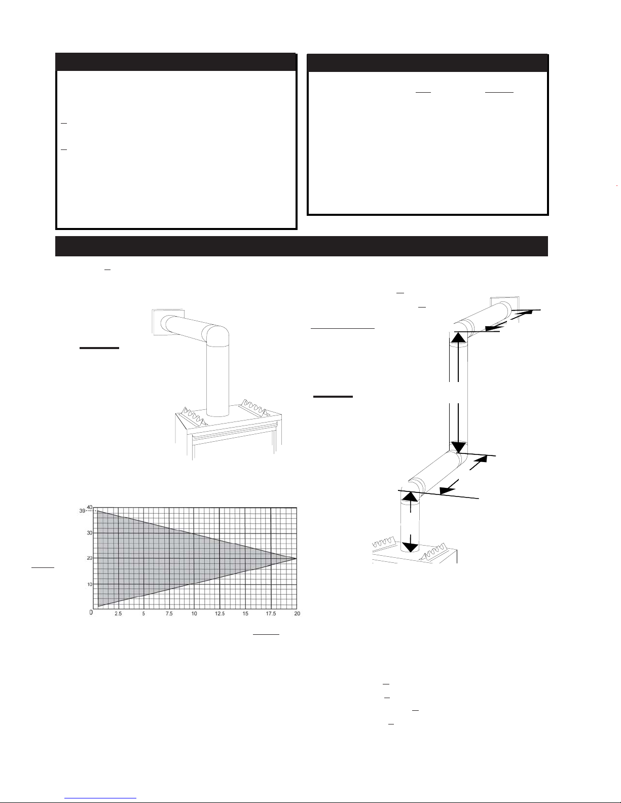
TOP EXIT / HORIZONTAL TERMINATION
when (HT) < (VT)
Simple venting configuration (only one 90° elbow)
FIGURE 4
ELBOW VENT LENGTH VALUES
feet inches
1° 0.03 0.5
15° 0.45 6.0
30° 0.9 11.0
45° 1.35 16.0
90°* 2.7 32.0
* the first 90° offset has a zero value and is shown in
the formula as -90°
For vent configurations requiring more than one 90° elbow, the following formulas apply:
Formula 1: HT < V
Formula 2: HT + VT < 40 feet
Example 1:
T
90°
H
2
See graph to determine the required vertical rise VT for the
required horizontal run H
.
T
VERTICAL
RISE IN
FEET
V
T
HORIZONTAL VENT RUN PLUS OFFSET IN FEET
The shaded area within the lines represents acceptable
values for HT and VT.
W415-0434 / C / 03.24.05
FIGURE 5
90°
V
1
V
2
H
V1=3 ft
V
=8 ft
2
VT=
V1 +
V2 =
3 + 8 = 11 ft
H1= 2.5 ft
H
=2 ft
2
= H1 + H2 = 2.5 + 2 = 4.5 ft
H
R
=.
H
H
O
T
HT= HR + HO = 4.5 + 5.4 = 9.9 ft
H
T
Formula 1: H
Formula 2: H
03(three 90° elbows - 90°) = .03(270° - 90°) = 5.4 ft
+ VT = 9.9 + 11 = 20.9 ft
< V
T
9.9 < 11
20.9
T
+ VT < 40 feet
T
< 40
Since both formulas are met, this vent configuration is acceptable.
90°
1
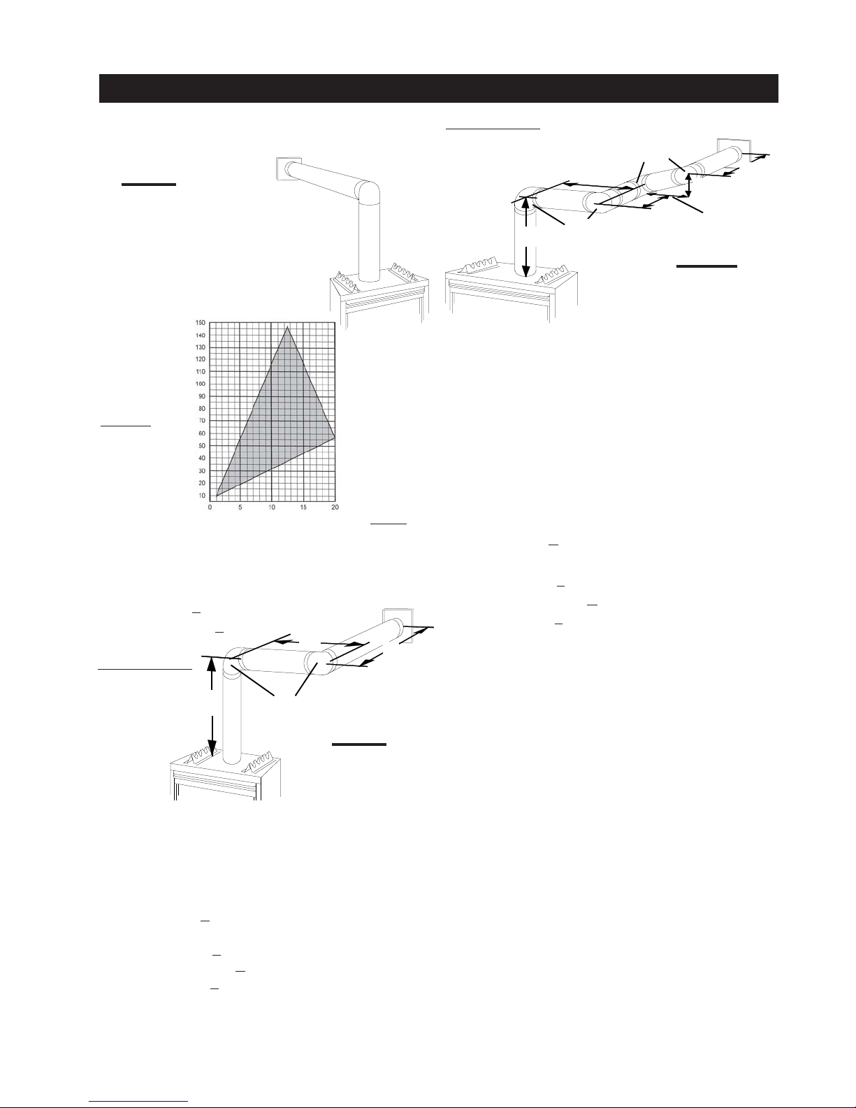
TOP EXIT / HORIZONTAL TERMINATION
7
when (H
) > (VT)
T
Simple venting configuration (only one 90° elbow)
FIGURE 6
See graph to determine the required vertical rise V
HT.
for the required horizontal run
T
REQUIRED
VERTICAL
RISE IN
INCHES
V
T
HORIZONTAL VENT RUN PLUS OFFSET IN FEET
H
T
The shaded area within the lines represents acceptable
values for HT and VT.
For vent configurations requiring more than one 90° elbow
the following formulas apply:
Formula 1: HT< 4.2 V
T
Formula 2: HT+ VT< 24.75 feet
H
1
Example 2:
H
2
Example 3:
90°
H
1
V
V
1
V
2
V
T
H
1
H
2
H
3
H
4
H
R
H
O
H
T
=4 ft
= 1.5 ft
= V1 + V2 = 4 + 1.5 = 5.5 ft
=2 ft
=1 ft
=1 ft
= 1.5 ft
= H1 + H2 + H3 + H4 = 2 + 1 + 1 + 1. 5 = 5.5 ft
= .03(four 90° elbows - 90°) = .03(360° - 90°) = 8.1 ft
= HR + HO = 5.5 + 8.1 = 13.6 ft
90°
1
HT + VT= 13.6 + 5.5 = 19.1 ft
Formula 1:HT < 4.2 V
T
4.2 VT = 4.2 x 5.5 = 23.1 ft
13.6 < 23.1
Formula 2:HT + VT < 24.75 feet
19.1 < 24.75
Since both formulas are met, this vent configuration is acceptable.
H
2
V
2
H
3
FIGURE 8
H
4
V
1
V
H
H
H
H
H
HT + VT=
= VT = 6 ft
1
=3 ft
1
=5 ft
2
= H1 + H2 = 3 + 5 = 8 ft
R
= .03(two 90° elbows - 90°) = .03(180° - 90°) = 2.7 ft
O
= HR + HO = 8 + 2.7 = 10.7 ft
T
10.7 + 6 =16.7
Formula 1: HT < 4.2 V
90°
T
4.2 VT = 4.2 x 6 = 25.2 ft
10.7 < 25.2
Formula 2: HT + VT < 24.75 feet
16.7 < 24.75
Since both formulas are met, this vent configuration is acceptable.
FIGURE 7
W415-0434 / C / 03.24.05
8
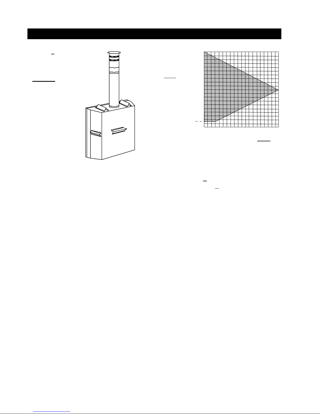
VERTICAL TERMINATION
when (HT) < (VT)
Simple venting configurations
FIGURE 9
See graph to determine the required vertical rise VT for the
required horizontal run H
.
T
40
REQUIRED
VERTICAL RISE
30
IN FEET
V
T
HORIZONTAL VENT RUN PLUS OFFSET IN FEET
20
10
3
0
5101520
H
The shaded area within the lines represents acceptable
values for HT and VT.
For vent configurations requiring more than zero 90° elbow
(top exit) or one 90° elbow (rear exit), the following formulas apply:
Formula 1: HT< V
T
Formula 2: HT+ VT < 40 feet
T
W415-0434 / C / 03.24.05
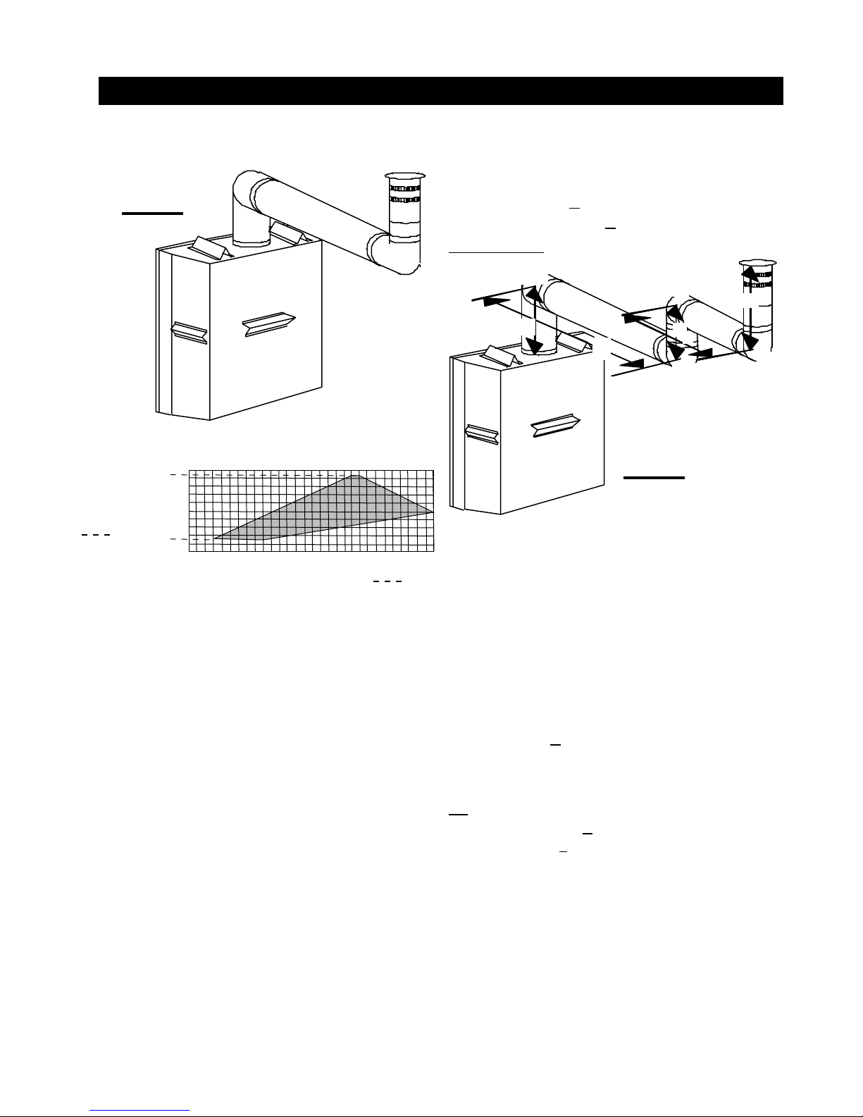
VERTICAL TERMINATION
9
when (HT) > (VT)
Simple venting configurations
FIGURE 1 0
See graph to determine the required vertical rise VT for the
required horizontal run H
20
MAXIMUM
VERTICAL
RISE IN
FEET
V
T
19
10
3
0
5101520
.
T
25 30
HORIZONTAL VENT RUN PLUS OFFSET IN FEET
The shaded area within the lines represents acceptable
values for H
and VT.
T
For vent configurations requiring more than two 90°
elbow the following formulas apply:
Formula 1: HT< 3V
T
Formula 2: HT+ VT < 40 feet
Example 7:
90°
90°
V
1
H
1
V
2
90°
FIGURE 11
V
1
V
2
V
3
T
V
T
H
1
H
2
H
R
H
O
H
T
HT+ VT = 16.1 + 4.5 = 20.6 ft
=2 ft
=1 ft
=1.5 ft
=
V1 +
V2 +
V3=
2 + 1 + 1.5 = 4.5 ft
=6 ft
=2 ft
= H1 + H2 = 6 + 2 = 8 ft
= .03(four 90° elbows - 90°)
= .03(90 + 90 + 90 + 90 - 90) = 8.1 ft
=
HR +
HO= 8 + 8.1 = 16.1 ft
H
V
3
2
90°
Formula 1:
HT< 3V
T
3VT=
3 x
4.5 = 13.5 ft
16.1 > 13.5
Since this formula is not met, this vent configuration is
unacceptable
Formula 2:
.
HT+ VT < 40 feet
20.6 < 40
Since only formula 2 is met, this vent configuration is unacceptable and a new fireplace location or vent configuration
will need to be established to satisfy both formulas.
W415-0434 / C / 03.24.05
 Loading...