

Page 1
INSTALLER: THESE INSTRUCTIONS MUST BE CONVEYED TO AND REMAIN WITH THE HOMEOWNER.
CERTIFIED IN CANADA TO CAN/CSA 22.2 #B40.0 - M87 & R91 B140.1 & B140.3 CERTIFIED IN THE UNITED STA TES TO UL 896 - 199
INSTALLATION AND OPERATION INSTRUCTIONS FOR
OIL-FIRED CAST IRON STOVE
MODEL
OS10
Wolf Steel Ltd., RR#1, 9 NAPOLEON RD.,
Barrie, ON., Canada L4M 4Y8 (705)721-1212
Fax: (705)722-6031 Email: ASK@NAPOLEON.ON.CA
Web: WWW.NAPOLEON.ON.CA
R-2000
ISO 9002 CERTIFIED
Registered Quality
System
R
WORLD RECOGNITION FOR QUALITY
WS-415-108 / 09.29.97
Page 2

2
TABLE of CONTENTS
PG 2-4 INTRODUCTION
Warranty
General Information
Care of Enamelled Parts
Care of Glass
4-7 INSTALLATION
Unit Specifications
Locations and Clearances
Safety Precautions
Draft Air
Outside Air
Chimney Specifications
Chimney Connection
Chimney Installation
Adding Chimney Sections
7 FINISHING
Leveling the Stove
Ash Tray Installation
PLEASE RET AIN THIS MANUAL FOR FUTURE REFERENCE
PG 7 FUEL SUPPL Y
8-9 OPERATING INSTRUCTIONS
Understanding Your Stove
Lighting Instructions
Shut Down
10 ADJUSTMENTS
Oil Flow Adjustment
Chimney Draft Adjustment
Overheating
11 MAINTENANCE
Seasonal Maintenance
Chimney Inspection and Maintenance
Gasket Replacement
12-13 REPLACEMENTS
Ordering Replacement Parts
Replacement Parts
14 TROUBLE SHOOTING
INTRODUCTION
WARNING
• The stove is an oil-fired stove. Do not burn wood or other materials in this stove.
• Adults and especially children should be alerted to the hazards of high surface temperatures and should stay
away to avoid burns or clothing ignition. Supervise young children when they are in the same room as the stove.
• Due to high temperatures, the stove should be located out of traffic and away from furniture and draperies.
• Clothing or other flammable material should not be placed on or near the stove.
• Do not allow anyone to operate this appliance unless they are thoroughly familiar with the operating instructions.
• The use of a firescreen is strongly recommended as a further safeguard.
• It is imperative that the controls, burner, its passageway in the stove and venting system are kept clean. The
stove and its venting system should be inspected before use and at least annually by a qualified service person.
More frequent cleaning may be required due to excessive soot build-up. The stove area must be kept clear and
free from combustible materials, gasoline and other flammable vapours and liquids.
• Under no circumstances should this stove be modified.
• This stove must not be connected to a chimney flue pipe serving another appliance.
• Do not draw combustion air from a wall, floor or ceiling cavity or from an enclosed area such as an attic, a
basement or a garage.
• Do not use this stove if any part has been under water. Immediately call a qualified service technician to inspect
the stove and to replace any part of the control system which has been under water.
• Do not operate the stove with the glass door opened, cracked or broken. Replacement of the glass should be
done by a licensed or qualified service person.
• Do not strike or slam shut the stove glass door.
Page 3

NAPOLEON oil stoves are manufactured under the strict Standard of the World Recognized
ISO9001 Quality Assurance Certificate.
NAPOLEON products are designed with superior components and materials, assembled by trained craftsmen who
take great pride in their work. The complete stove is thoroughly inspected by a qualified technician before packaging
to ensure that you, the customer, receives the quality product that you expect from NAPOLEON.
NAPOLEON OIL STOVE PRESIDENT'S LIFETIME LIMITED WARRANTY
The following materials and workmanship in your new The following materials and workmanship in your new NAPOLEONNAPOLEON oil stove are warranted against defects oil stove are warranted against defects
for as long as you own the stove. This covers: combustion chamber, heat exchanger, borosilicate glass (thermalfor as long as you own the stove. This covers: combustion chamber, heat exchanger, borosilicate glass (thermal
breakage only), gold plated parts against tarnishing, and porcelainized enamelled components.breakage only), gold plated parts against tarnishing, and porcelainized enamelled components.
Wearable parts such as carburetor and catalytic components, oil reservoir, burner, flue baffle and high temperatureWearable parts such as carburetor and catalytic components, oil reservoir, burner, flue baffle and high temperature
paint are covered and paint are covered and NAPOLEON NAPOLEON will provide replacement parts free of charge during the first year of thewill provide replacement parts free of charge during the first year of the
limited warranty.limited warranty.
3
Labour related to warranty repair is covered free of charge during the first year. Repair work, however, requiresLabour related to warranty repair is covered free of charge during the first year. Repair work, however, requires
the prior approval of an authorized company official. Labour costs to the account of the prior approval of an authorized company official. Labour costs to the account of NAPOLEONNAPOLEON are based on are based on
a predetermined rate schedule and any repair work must be done through an authorized a predetermined rate schedule and any repair work must be done through an authorized NAPOLEONNAPOLEON dealer. dealer.
CONDITIONS AND LIMITATIONS
NAPOLEON warrants its products against manufacturing defects to the original purchaser only -- i.e., the individual or legal entity (registered customer) whose name appears
on the warranty registration card filed with NAPOLEON -- provided that the purchase was made through an authorized NAPOLEON dealer and is subject to the following
conditions and limitations:
This factory warranty is non-transferable and may not be extended whatsoever by any of our representatives.
The oil stove must be installed by an authorized service technician or contractor. Installation must be done in accordance with the installation instructions included with the
product and all local and national building and fire codes.
This limited warranty does not cover damages caused by misuse, lack of maintenance, shipping, accident, alterations, abuse or neglect. Parts installed from other manufacturers will nullify this warranty.
This limited warranty does not cover chipping of flaking of porcelainized enamelled components where the stove has been installed in a salt air or highly humid environment
that may be corrosive or cause rust. Stove inspection for damage to the enamel should be done prior to accepting it.
This limited warranty further does not cover any scratches, dents, corrosion or discolouring caused by excessive heat, abrasive and chemical cleaners nor chipping on
porcelain enamel parts, nor any venting components used in the installation of the stove.
In the first year only, this warranty extends to the repair or replacement of warranted parts which are defective in material or workmanship provided that the product has been
operated in accordance with the operation instructions and under normal conditions.
After the first year, with respect to the President's Limited Lifetime Warranty, NAPOLEON may, at its discretion, fully discharge all obligations with respect to this warranty by
refunding to the original warranted purchaser the wholesale price of any warranted but defective part(s).
After the first year, NAPOLEON will not be responsible for installation, labour or any other costs or expenses related to the reinstallation of a warranted part, and such
expenses are not covered by this warranty.
Notwithstanding any provisions contained in the President's Limited Lifetime Warranty, NAPOLEON’S responsibility under this warranty is defined as above and it shall not in
any event extend to any incidental, consequential or indirect damages.
This warranty defines the obligations and liability of NAPOLEON with respect to the NAPOLEON oil stove and any other warranties expressed or implied with respect to this
product, its components or accessories are excluded.
NAPOLEON neither assumes, nor authorizes any third party to assume, on its behalf, any other liabilities with respect to the sale of this product. NAPOLEON will not be
responsible for: over-firing, downdrafts, spillage caused by environmental conditions such as rooftops, buildings, nearby trees, hills, mountains, inadequate vents or ventilation,
excessive venting configurations, insufficient makeup air, or negative air pressures which may or may not be caused by mechanical systems such as exhaust fans, furnaces,
clothes dryers, etc.
Any damages to the stove, combustion chamber, enamelled finish or other component due to water, weather damage, long periods of dampness, condensation, damaging
chemicals or cleaners will not be the responsibility of NAPOLEON.
The bill of sale or copy will be required together with a serial number and a model number when making any warranty claims from your authorized dealer. The warranty
registration card must be returned within fourteen days to register the warranty.
NAPOLEON reserves the right to have its representative inspect any product or part thereof prior to honouring any warranty claim.
ALL SPECIFICATIONS AND DESIGNS ARE SUBJECT TO CHANGE WITHOUT PRIOR NOTICE DUE TO ON-GOING PRODUCT IMPROVEMENTS. NAPOLEON® IS A REGISTERED
TRADEMARK OF WOLF STEEL LTD. PATENTS U.S. 5.303.693.801 - CAN. 2.073.411, 2.082.915. © WOLF STEEL LTD.
Page 4

4
GENERAL INFORMATION
Nominal heat Oil consumption ** Chimney draft required Weight Flue outlet
output max speed min speed max speed min speed outside diameter
34,130 BTU/hr .275 US gal/hr .055 US gal /hr 20 Pa 6 Pa 260 lbs 5 inches
10 kW 1.25 litre/h ¼ litre/h @ .08 w.c.g @.024 w.c.g. 118 kg 120-125 mm
** 1 pint = 0.568 261 litre 1 ml = 0.001 760 pint 1 quart = 1.136 522 litres 1 gallon = 4.546 090 litres 1 US gal = 3.785 412 litres
1 litre = 1.760 pints 1 litre = 0.879 877 quart 1 litre = 0.22 gal
Pints, quarts and gallons are Canadian unless otherwise noted.
To determine the flow rate, disconnect the feed line from the carburetor to the burner. Place the container for measuring
the calibration under the carburetor outlet.
CARE OF ENAMELLED P ARTS
Do not use abrasive cleaners to clean these parts. Buff lightly with a clean, dry cloth. Porcelain enamel components must be handled with care. The baked-on finish is "glasslike". If struck, it will chip. Touch-up paint is
available through your Napoleon dealer.
CARE OF GLASS
If the glass is not kept clean permanent discolouration and / or blemishes may result. Normally a hot burn will
clean the glass. The most common reason for dirty glass is running the unit at a low burning rate. If it is
necessary to clean the glass, use a soft cloth with a nonabrasive cleaner. Coarse cleaning materials may cause
scratches or otherwise damage the glass. Scratches can develop into cracks or breaking of the glass. DO NOT
CLEAN GLASS WHEN HOT!
The glass is very strong and comes in strips for maximum performance. However, always close the door gently.
If the glass should ever crack while the fire is burning, do not open the door until the fire is out and do not
operate the stove again until the glass has been replaced with new borosilicate glass, available from your
Napoleon / Wolf Steel Ltd. dealer. DO NOT SUBSTITUTE MATERIALS. Check gaskets and seals regularly.
INSTALLATION
SPECIFICATIONS
16” (402mm)
15” (383mm)
5”ø (ø125mm)
20” (505mm)
21½” (544mm)
WARNING: Improper installation, adjustment, alteration, service or maintenance can
cause injury or property damage. Refer to this manual. For assistance or additional information consult a qualified installer, service agency or the oil supplier.
24½”
(620mm)
27” (678mm)
FIGURE 1
Page 5
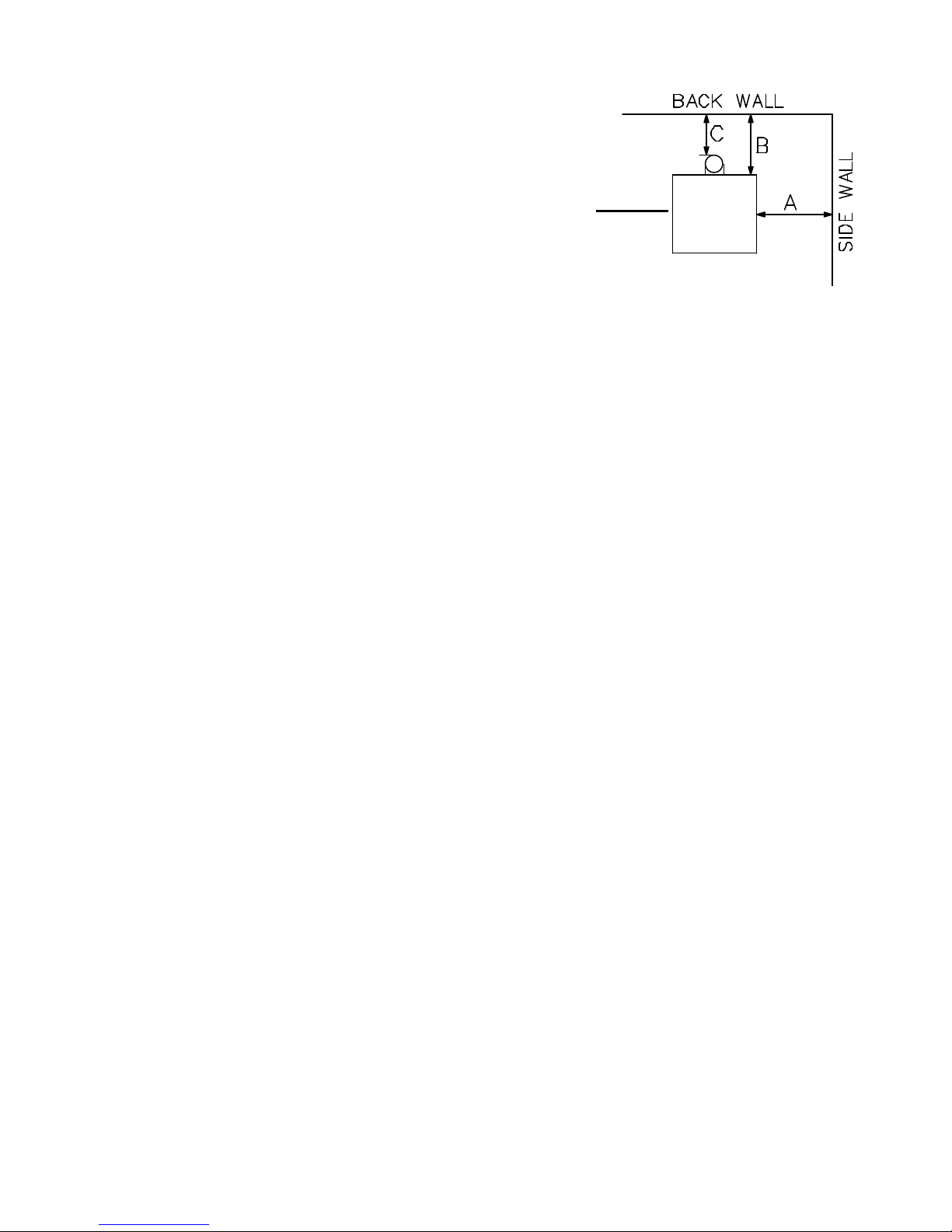
LOCATION AND CLEARANCES
If the stove is to be installed on a combustible floor, it must be placed
on a approved noncombustible hearth pad, that extends the full width
and depth of the unit - 24½" x 21½" (620 mm x 544 mm).
5
Maintain these minimum clearances to combustibles:
A (side wall to side of stove) 12 inches (300mm)
B (back wall to back of stove) 19 inches (483mm)
C (back wall to back of chimney connector) 12 inches (300mm)
If reduced clearances are needed, obtain requirements from your local building code authorities.
FIGURE 2
SAFETY PRECAUTIONS
Please read the installation instructions carefully, prior to installing the oil stove.
Your Napoleon oil stove must be installed in accordance with all national and local building code standards.
Consult the authority having jurisdiction (such as municipal building department, fire department, fire prevention
bureau, etc.) to determine the need to obtain a permit. If you are in doubt about the proper installation for your
situation, contact your dealer or local building or fire official.
DRAFT AIR
Most of the heat generated by the oil stove is used to warm the room air. However, part of the generated heat
escapes as exhaust gas through the chimney, creating a ‘chimney draft’. To ensure proper operations of the
stove, it must be connected to a chimney having a sufficient draft capacity to operate the stove satisfactorily.
Flue draft, measured as negative pressure in the chimney, is created by the hot, rising combustion gas. The
draft, in turn, permits combustion air to enter the burner and emit the exhaust gases from the chimney to
complete the combustion cycle. A draft of 0.08" water column for maximum speed burn and 0.024" for minimum speed burn is rated best to obtain the utmost performance of the oil stove.
Basic criteria essential to create and maintain chimney draft are:
1. Availability of combustion air
2. Diameter and height of chimney.
3. Heat generated by the fire.
These segments work together to create the chimney draft. To alter one of them will affect the other two and
change the amount of draft in the chimney and ultimately the stove’s performance. To ensure that adequate
chimney draft is maintained, the chimney should be kept clean and without cracks. As soon as the oil stove has
been installed, the chimney draft should be checked with a draftmeter. In order to insert the draftmeter probe
into the chimney connector, drill a ¼” hole at the rear of the connector joint approximately 6” from the rear of the
flue collar. This may then be sealed with a screw once all testing has been completed. Flue draft is measured
when the oil stove is hot (after a minimum use of 30 minutes) to establish a true reading of the draft. For the
recommended operating draft level, see ‘General Information’ on page 4. Draft adjustment can be made through
use of the draft regulator located at the back of the oil stove (item 12, figure 9). In the event that the chimney
draft is excessive or irregular, a draft stabiliser should to be fitted to the chimney.
OUTSIDE AIR
The oil burning stove consumes about 4000 ft3 of air per US gallon of oil (30 m3 of air per litre of oil). This air is
introduced into the burner through air inlets and exits the chimney as combustion gas. For the oil stove to
function properly, an adequate supply of combustion air is required. There are many other appliances in your
home competing for air such as: a kitchen range hood, forced air heating devices, clothes dryer or a bathroom
exhaust fan. Clothes dryers exhaust 400 CFM (cubic feet / minute); range hoods and exhaust fans can exhaust
up to 150 CFM. If there is insufficient combustion air, you may need to open a door or window to avoid adversely
affecting the performance of the oil stove.
The manufacturer of the stove and/or his agent is not responsible for any smoking or related problems or
damages resulting from the lack of adequate combustion air. It is the responsibility of the installation contractor
to ensure that adequate combustion air is available to the stove at all times.
Page 6

6
THE TOTAL SMOKE PIPE LENGTH SHOULD NOT EXCEED 40% OF THE CHIMNEY HEIGHT ABOVE
THE STOVE TO A MAXIMUM HORIZONTAL RUN OF 10 FEET.
All smoke pipe must slope upwards at a minimum of 1/4" per foot (6mm/0.3m) and all connections
must be tight and secured by three sheet metal screws equally spaced.
An uninsulated smoke pipe shall not pass through an attic, roof space, closet or similar concealed
space, or through a floor, ceiling, wall or partition, or any combustible construction.
CHIMNEY SPECIFICA TIONS
If the chimney is ‘cold’, the normal combustion cycle will not work. A cold chimney may be caused by disuse,
being too large, not insulated, being external or not high enough. Exterior chimneys cool rapidly, causing poor
draft and condensation.
CHIMNEY CONNECTOR
The stove should be located as close as possible to the chimney to avoid draft problems. Horizontal flue
connectors restrict the establishment of the required chimney draft and thereby prevent the normal functioning
of the stove. Ensure that the connection is supported and fastened to the stove. Example: Wrap plumber’s
strapping around the vertical section of the connector and screw to either edge of the rear heat shield. Ensure
that the strapping is snug fitting (As an alternative support, drill three evenly spaced holes into the connector
and flue collar and attach screws.)
A chimney connector may be used only within the room where the unit is located, between the oil stove and the
chimney but never passing through a combustible ceiling or wall. Minimum connector clearances to combustibles
are to be maintained. If necessary, where local codes allow, a wall thimble may be used.
There are two types of chimney connectors:
THE SINGLE WALL CONNECTOR: This connector must be 316 grade 26 gauge stainless steel or 1 mm
vitreous enamelled steel and with a 5" (125 mm) diameter. Secure the connector joints with 3 sheet metal
screws. The joints are to be airtight.
All connector sections must be attached to the unit and to each other with the crimped or male end pointing
down towards the oil stove.
CHIMNEY INST ALLATION
An A-Vent chimney, either 4" (100 mm.) or 5" (125 mm.) in diameter may be used. Six inch diameter ‘L’ vent
may be used but only with No. 2 furnace oil. The minimum chimney height is to be 15 feet or 4.6 metres
measured from the appliance flue collar to the top of the chimney but not including any chimney caps. Installation of all chimney systems is to be in accordance with the chimney manufacturers installation instructions. If
the stove is to be connected to a masonry chimney, a stainless
steel liner is required.
1. Move the stove into position with the flue centred, midpoint between two joists to prevent having to cut them. Use a
plumb bob to line up the centre.
2. Cut and frame an opening in the roof to provide a 2" clearance between the outside of the chimney and any combustible
material. DO NOT FILL THIS SPACE WITH ANY TYPE OF
MATERIAL.
Nail headers between the joist for extra support. Firestop
spacers must be placed on the bottom of each framed opening
in any floor or ceiling that the chimney passes through. FIGURE
3.
3. Hold a plumb bob from the underside of the roof to determine where the opening in the roof should be. Cut
and frame the roof opening to maintain proper 2" clearances. FIGURE 4.
FIGURE 3
FIGURE 4
Page 7

ADDING CHIMNEY SECTIONS
Add chimney sections, twist locking (clockwise) securely, to the required height.
Safety requirements dictate that the chimney must be at least 3 feet (915 mm) higher
than the highest point where it passes through the roof and at least 2 feet (610 mm)
higher than the highest part of the roof or structure that is within 10 feet (3.05 m) of
the chimney, measured horizontally. FIGURE 5. Obstacles close to the chimney
may cause downdrafts which may be prevented by the installation of a chimney cap
fitted with a wind deflector. If your chimney system is enclosed within the attic area,
a rafter radiation shield is required.
FINISHING
LEVELLING THE STOVE
Four adjusting bolts with caps are supplied and which have been placed in the burner
for packing purposes only. Fit the screws and caps to the bottom of the stove legs.
Place the level on the burner ring and adjust the bolts until the burner has reached a
level position.
FIGURE 6
7
FIGURE 5
A
ASH TRA Y INST ALLATION
To avoid damage to the ash tray during transport, it has been disconnected and stored behind the main door of the oil stove. To reinstall the
ash tray to the front of the oil stove, tilt the tray at a 45° angle, center onto
tab ‘A’ and lower into place.
FIGURE 7
FUEL SUPPLY
The NAPOLEON OS10 cast iron oil burning stove is designed and fitted with a special carburetor to use only a
specific category of fuel oil. This fuel oil must be clean and free of any dirt or traces of water. Impurities in the
fuel oil can cause a reduced efficiency level.
The only fuel to be used with this heating appliance is FURNACE OIL NO. 2 OR NO. 1.
DO NOT allow the oil tank to get empty. To do so may cause the stove to soot and increase the risk
of a chimney fire.
Never use gasoline, motor oil or any gasoline contaminated oil.
The oil tank should be located in such a manner to prevent exposure to direct sunlight or be close
to any source of intense heat.
The fuel system of an oil burning stove can either be a gravity system or one equipped with a fuel suction pump.
The system selection depends on the location of the fuel tank.
The fuel system of this stove is designed to supply fuel by gravity pressure only. If the supply tank location is
lower than the stove, it will be necessary to use the Napoleon SP32 suction pump. The SP32 should be installed
a minimum of 12” above the stove carburetor and a minimum of 6” horizontally from the stove. This height
difference will provide the necessary head pressure to feed the fuel to the carburetor.
Also, if the height difference between oil tank and oil stove is in excess of 8 feet (2.44 metres), an oil pressure
regulator must be fitted close to the carburetor to mitigate the pressure in the feeder line. The oil feeder line or
oil supply line must be copper tubing with a minimum outside diameter of 5/16" (8 mm). Maximum pressure for
the feed line is 3 psi (20 kPa). A safety shut-off should be installed behind the stove.
Page 8

8
OPERATING INSTRUCTIONS
UNDERSTANDING YOUR OIL STOVE
1
1. Relief Door Plate
8
2. Main Door
2
3
4
5
10
6
3. Door Handle
4. Catalyser Top
5. Upper Ring
6. Catalyser
7. Burner
8. Flue Collar
9. Reflector
10. Tray
9
11. Control Knob
12. Draft Regulator
13. De-scaling Lever
14. Safety Lever
15. Control filter access
16. Min. Setting adjustment
7
Screw
17. Max. Setting adjustment
Screw
18. Carburetor
11
12
13
14
16
15
FIGURE 9FIGURE 8
17
18
Furnace oil is fed from the tank to the burner floor (A) where
is it ignited by means of a firestarter. The heat produced by
this flame brings the burner temperature to the required level
to vaporize the fuel. Oil will only burn as a vapour not a
liquid. Room combustion air enters the burner through the
air inlet holes (B).
The stove carburetor contains a filter to trap impurities. This
filter must be cleaned periodically with the frequency depending on the fuel purity. A safety lever controls fuel flow.
Oil can only enter the float chamber when the safety lever is
depressed. Oil temperature variations will affect the oil flow
into the float chamber. A float in the chamber raises the fuel
level available to the burner. The carburetor is also controlled by a control knob which turns from 0 (off) to 6
(high setting).
In the center of the burner is the catalyser (C) which aids in vaporizing the fuel. When the stove is operation, the
catalyser glows red. The stove should not be used without both the catalyser, catalyser top (D) and ring (E).
To the right of the unit, just below the side panel is a small push rod called a de-scaling lever, (item 13, figure 9),
that should be pushed and pulled in and out as well as turning slightly at the same time to keep the inlet pipe
clear of carbon buildup. This should be done on a weekly basis.
Because the draft from the chimney is never uniform, a draft regulator has been added to ensure a constant air
intake to the burner regardless of external factors.
Never light the burner if any oil is in the burner pot.
The burner pot must be cleaned thoroughly prior to lighting or relighting.
Keep the door of the oil stove closed when it is in operation except during lighting procedures.
B
D
A
C
E
SECONDARY AIR
PRIMARY AIR
FIGURE 10
Page 9

LIGHTING INSTRUCTIONS
Proceed once installation is complete and all necessary instructions have been followed:
When lit for the first time, the stove will emit a slight odour for a few hours. This is a normal temporary condition
caused by the curing and the "burn-in" of internal paints and lubricants used in the manufacturing process and
will not occur again. After extended periods of non-operation such as following a vacation or a warm weather
season, the stove may emit a slight odour for a few hours. This is caused by dust particles burning off. In both
cases, open a window to sufficiently ventilate the room.
FIGURE 11
1. Through the open door, remove the catalyser components
(items C, D and E, figure 10) from the burner.
2. Ensure that the burner pot is dry, and clean with no oil remaining.
3. Place a piece of thumb nail size
firestarter gel (methane pellet or
paraffin paper or 2 tablespoons of methylated spirits) into the
burner pot.
NEVER USE ALCOHOL OR GASOLINE AS A
FIRESTARTER.
Light with a long taper or wadded piece of paper. Immediately replace the catalyser components. FIGURE 10. Ensure
that the top is centred.
9
4. Set the control knob to ‘0’. FIGURE 11. Depress safety lever
FIGURE 12
6. Allow 10 to 15 minutes of low burn for the flames and chimney draft to stabilize. The catalyser should glow
red before changing to a higher setting.
7. The stove may now be adjusted to the desired heat setting, usually between 2 and 4. Never switch straight
from 1 to 6. A longer burner life will be achieved if the regulator is moved one setting at a time leaving approx.
5 minutes between settings.
If the fire goes out, return the regulator control knob to the ‘0’ setting. Let the burner cool off completely before
repeating the lighting procedure. Clean out any oil before relighting.
NEVER OPERATE THE STOVE WITH THE DOOR OPEN OR AJAR.
to allow oil flow into the regulator. FIGURE 12.
5. Turn the regulator control knob to the # 1 dial setting.
SHUT DOWN
1. Turn the control knob to 0 setting.
2. Lift the safety lever.
3. Turn off the oil tank fuel supply valve.
The oil tank fuel supply valve should always be shut if the oil stove is not in operation.
Page 10

10
ADJUSTMENTS
OIL FLOW ADJUSTMENTS
Always burn the stove on low for at least 15 minutes before
attempting to adjust the flow.
TURN THE SCREW ONLY A QUARTER TURN AT A
TIME. WAIT 10 TO 15 MINUTES BETWEEN ADJUST-
MENTS TO ALLOW THE FIRE TO STABILISE.
The oil flow setting is done by the manufacturer and normally should not require any adjustment. If the burner fails to
respond to the control knob settings, other possible causes
should be checked (chimney draft, dirty filter or the oil supply
line) prior to attempting to adjust the carburetor.
A
ADJUSTMENT AT MINIMUM SPEED: Turn the control knob
‘A’ to the # 1 dial setting and allow the burner to run for a few
moments. The flame must completely cover the bottom of
the burner pot and the catalyser should glow red. If the flame
is too small, the oil stove will quickly soot up. Turn the set
screw ‘B’ FIGURE 12 (item 16, Figure 9), located on the top of
the carburetor, clockwise with a screwdriver to increase the flow
of oil.
If the flame is too high, reduce the oil flow by turning the set screw counter-clockwise. The flames should be
blue with occasional yellow tips. The catalyser should glow red.
FIGURE 12
C
B
ADJUSTMENT AT MAXIMUM SPEED: Gradually turn the control knob ‘A’ to dial setting # 6 and allow the burner
to run for a few moments. The flame should be in a cone form with the top level with the upper part of the door.
If the flame is too low, the oil flow rate should be increased by turning the set screw ‘C’ FIGURE 12,
(item 17, Figure 9) on the carburetor counter-clockwise. If the flame is too high, turn the screw clockwise. The
flames should have only occasional contact with the burner ring. The bottom 2” (50 mm) of the flames should be
blue in colour with the rest yellow.
CHIMNEY DRAFT ADJUSTMENT
A volume of air, depending on height and diameter of the flue system, is contained in the chimney. This air starts
to rise as it is heated by the burning stove and begins the draft cycle. The amount of draft depends on the
volume of air within the chimney system and the temperature of that air. Too large a flue could cause cooling of
the flue gases, resulting in a poor draft and stove performance.
The stove is equipped with a draft regulator to ensure a constant and stable air intake despite external variations in wind strengths and other factors.
Adjustments to the draft with the regulator should be carried out when the chimney is hot (after a minimum 30
minutes of operations). See Page 4, General Information, for chimney draft requirements.
OVERHEATING
Adjusting the control knob to a high setting prematurely allows too much oil to enter the burning pot. This and/
or the lack of sufficient draft creates a fire intensity which in turn creates vibrations. Similarly, if the oil stove or
the chimney connector start to glow red, the appliance is being overheated. Turn off the oil supply until the fire
has decreased to a normal steady burn.
Adjustments, if any, to your oil stove have been made by your installer. Do not attempt any further adjustments
yourselves but report any failures or shortcomings in the stove’s performance to your authorized dealer.
Page 11

MAINTENANCE
WEEKLY - DESCALE
Push and pull the de-scaling lever in and out as well
as turning slightly at the same time completely two or
three times. Push in for normal burner operations or
before relighting.
EVERY 3 TO 4 MONTHS - CLEAN BURNER
Remove all three catalyser components. FIGURE 10.
Remove any carbon residue and remaining oil from the burner
using a slightly damp cloth. Buff dry before reinstalling.
11
A
C
FIGURE 13
D
E
F
G
H
B
YEARLY - CLEAN CARBURETOR FIL TER
1. Set the control knob to 0.
2. Turn off oil supply at the valve or the tank valve.
3. Raise the safety lever (D).
4. Place a container under the carburetor to contain any spillage. Remove
the filter plug held on with two screws.
5. Pull out the filter (E) and clean in oil using a soft brush. Never use a wire
brush.
6. Replace filter and plug.
Clean all enamelled stove panels and the outside of the glass using a slightly
dampened cloth. Never clean when the stove is hot
A - control knob
B - thermostat control
C - oil level regulator
D - safety lever
E - filter
F - main float
G - safety float
H - filter cavity
CHIMNEY INSPECTION AND MAINTENANCE
The chimney and the chimney connector must be inspected at least once every 3 months during the heating
season to ascertain whether there has been a buildup of soot in the system. If a soot buildup has occurred, it
should be removed to reduce the risk of chimney fires. The chimney is to be swept at least once a year. It is also
recommended that prior to every heating season the entire system be professionally inspected, cleaned and
repaired where necessary.
Page 12

12
DOOR GASKET REPLACEMENT
Check the door gasket periodically to ensure the seal is functioning properly and the door fits tight. Replace the
gasket if necessary.
REPLACEMENTS
ORDERING REPLACEMENT PARTS
Contact your dealer or the factory for questions concerning prices and policies on replacement parts. Normally
all parts can be ordered through your Napoleon dealer or distributor. When ordering replacement parts always
give the following information:
1. MODEL & SERIAL NUMBER OF FIREPLACE 3. PART CODE 5. FINISH
2. INSTALLATION DATE OF FIREPLACE 4. DESCRIPTION OF PART
REPLACEMENT PARTS
For warranty replacement parts, a photocopy of the original invoice will be required to honour the claim. Ordering Replacement Parts
When ordering spare parts, please indicate model number, colour code, parts description, and code number.
PART # CODE DESCRIPTION QTY PART # CODE DESCRIPTION QTY
1 100956 AXLE 01 27 262307 HEAT SHIELD TOP * 01
2 105383 BURNER 01 28 276216 REFLECTOR 01
3 109550 LEVELLER & CAP 04 29 300118 LEG 04
4 110105 DRAFT REGULATOR 01 30 300472 BASE 01
5 110405 HINGE PIN 6X35 02 31 301515 DOOR LOCK 01
6 119211 DE-SCALE LEVER 01 32 303718 RELIEF PLATE 01
7 134601 PIN 2X20 01 33 303828 FLUE COLLAR 01
8 134749 PIN 4X20 01 34 306266 BACK WALL 01
9 142301 ADHESIVE DOOR GASKET 1.32 m 35 309857 FRONT PLATE 01
10 142412 BURNER GASKET 1.00 m 36 309975 MAIN DOOR 01
11 149810 CONTROL KNOB 01 36 988805 COMPLETE DOOR 01
12 158541 HANDLE 01 36 988793 COMPLETE DOOR 01
13 161025 TOUCH-UP PAINT 01 37 310723 R. SIDE PANEL 01
14 162356 DESCRIPTIVE PLATE 01 38 310621 L. SIDE PANEL 01
15 164205 OIL-TIGHT NUT 02 39 312625 BURNER SUPPORT 01
16 165124 FLOAT REGULATOR FUEL 01 40 321903 RIM 01
17 179605 CONTROL SHAFT 01 41 352124 TOP PLATE 01
18 181604 CERAMIC ROPE 10X4 - RELIEF PLATE 1.00 m 42 407203 GLASS RETAINER 01
19 181612 CERAMIC ROPE ROUND 12Ø - TOP PLATE 3.16 m 43 407204 GLASS RETAINER 01
20 188791 REFRACTORY GLASS 11PC ** 01 44 982608 FEED LINE 01
21 205367 BACK PANEL 01 45 262214 SHIELD 01
22 221200 STRIKING PLATE 01 46 194401 CATALYSER COVER 01
23 222536 FLUE BAFFLE 01 47 194402 CATALYSER BODY 01
24 239714 BRACKET 01 48 198205 CATALYSER RING 01
25 239714 CARBURETOR SUPPORT 01 49 199204 REGULATOR FILTER 01
26 260568 BURNER HEAT SHIELD 01 50 142316 GLASS GASKET 7X3 1.00 m
51 261811 CARBURETOR HEAT SHIELD 01
52 327901 ASH TRAY 01
* HEAT SHIELD REQUIRED ON ENAMELLED STOVES ONLY. NOT NECESSARY ON BLACK PAINTED UNITS.
** FOR INDIVIDUAL GLASS PIECES, IDENTIFY THE PIECE NEEDED (#1 THROUGH #11, COUNTING FROM THE LEFT WHILE
FACING THE STOVE).
Page 13

13
Page 14

14
TROUBLE SHOOTING
PROBLEM TEST SOLUTIONSYMPTOM
Flames extinguish
during lighting.
Fire extinguishes
once firestarter has
burnt off.
Fire extinguishes
during use.
Flame is excessely
large, smokey and
sooty.
Stove burns noisily,
extinguishes and relights itself.
Fire smokes.
Soot build up noticed. Flame imbalance.
Very cold chimney.
No draft established
Fuel tank is empty.
Fuel valve is closed.
Main carburetor float not
engaging.
Safety lever will not engage.
Fuel tank is empty. - fill tank
Fuel adjustment made too
quickly.
Burner contains excess fuel
Insufficient air supply.
Downdraft or blockage in
chimney
Low flame setting incorrectly adjusted
Oil flow is too low on 1 setting.
Stove is not level. Flame
imbalance.
Catalyser not centered.
Uneven fuel distribution
resulting in secondary air
shortage.
- leave door ajar until fire has caught.
- fill tank
- open valve
- de-press the safety lever
- remove carburetor cover and drain secondary float well.
Check for cause of primary float failure.
- return control knob to ‘1’; wait for normal combustion.
(catalyser should glow red) Wait 5 to 15 minutes between
each adjustment.
- adjust to lower setting. If problem persists call your installer.
- increase fresh air supply (open door, window; add makeup air supply)
- check chimney for soot build up. Clean if necessary.
- ensure chimney height is sufficient and cap is not affected by any nearby obstructions.
- room is in negative pressure. Increase fresh air supply.
Check draft with draft meter and adjust if not to requirements. See page 4.
- adjust setting. See page 10 for instructions.
- adjust low flow rate while control is set on ‘1’.
Check level. Adjust if necessary.
Center catalyser assembly
Coke build up noticed.
Excessive air supply. - adjust draft.
 Loading...