

Napoleon LVX38, LVX50, LV50-2, LVX62, LVX74 Installation Manual
...
NATURAL GAS MODELS:
ADD PRODUCT CODE HERE (TRADE GOTHIC LT STD FONT)
ENGLISH
PROPANE GAS MODELS:
INSTALLATION MANUAL
SAFETY INFORMATION
!
WARNING
FIRE OR EXPLOSION HAZARD
Failure to follow safety warnings exactly
could result in serious injury, death, or
property damage.
- Do not store or use gasoline or other
fl ammable vapors and liquids in the vicinity of
this or any other appliance.
- WHAT TO DO IF YOU SMELL GAS:
• Do not try to light any appliance.
• Do not touch any electrical switch; do not
use any phone in your building.
• Immediately call your gas supplier from a
neighbour’s phone. Follow the gas
supplier’s instructions.
• If you cannot reach your gas supplier, call
the fi re department.
FRENCH
PG. 27
ADD MANUAL TITLE
PRODUCT NAME™
ADD ____ ILLUSTRATED
ADD PRODUCT IMAGE
- Installation and service must be
performed by a qualifi ed installer, service
agency, or the supplier.
This appliance may be installed in an aftermarket,
permanently located, manufactured home (USA
only) or mobile home, where not prohibited by
local codes.
This appliance is only for use with the type of gas
indicated on the rating plate. This appliance is
not convertible for use with other gases, unless
a certifi ed kit is used.
INSTALLER:
Leave this manual with the appliance
CONSUMER:
Retain this manual for future reference
Wolf Steel Ltd., 24 Napoleon Rd., Barrie, ON, L4M 0G8 Canada / 103 Miller Drive, Crittenden, Kentucky, USA, 41030
Phone 1 (866) 820-8686 • www.napoleonfi replaces.com • hearth@napoleonproducts.com
FOR INDOOR USE ONLY
CERTIFIED TO THE CANADIAN AND AMERICAN NATIONAL STANDARDS:
CSA 2.22 AND ANSI Z21.50 FOR VENTED DECORATIVE GAS APPLIANCES
FOR INDOOR USE ONLY
CERTIFIED TO THE CANADIAN AND AMERICAN NATIONAL STANDARDS:
CSA 2.22 AND ANSI Z21.50 FOR VENTED DECORATIVE GAS APPLIANCES
CSA /
INTERTEK
LOGO
$10.00
W415-1739 / C / 08.03.17

EN
table of contents
1.0 general information 3
2.0 installation planning 4
2.1 installation option 1 - open enclosure (enclosure stops short of the ceiling) 5
2.2 installation option 2 - front opening 5
2.3 installation option 3 - rear opening 6
2.4 installation option 4 - open enclosure with hard combustible valance 7
3.0 appliance overview 8
4.0 Dynamic Heat Control™ installation 9
4.1 high limit switch installation 11
5.0 minimum framing dimensions 13
6.0 minimum clearance to combustible enclosures 14
7.0 rough framing - before appliance installation 16
8.0 finish framing - after appliance installation 17
9.0 fastener placement restriction 21
10.0 finishing 22
11.0 minimum combustible mantel clearances 23
12.0 maximum protrusion 24
13.0 completed DHC installation checklist 25
note:
The information throughout this manual is believed to be correct at the time of printing. Wolf Steel
Ltd. reserves the right to change or modify any information within this manual at any time without
notice. Changes, other than editorial are denoted by a vertical line in the margin.
2
W415-1739 / C / 08.03.17
1.0 general information
WARNING
!
• Dynamic Heat Control™ MUST be installed during the installation of the appliance BEFORE appliance venting and gas
are installed.
• Ensure the appliance is completely cool before starting installation.
• To avoid danger of suffocation keep the packaging bag away from babies and children. Do not use in cribs, bed, carriages,
or play pens. This bag is not a toy. Knot before throwing away.
general information
EN
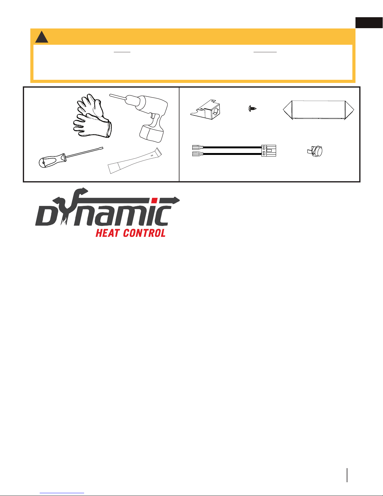
You will need:
Included in this kit
Bracket
Wire Harness
Dynamic Heat Control™ is a system for managing the
heat produced by the appliance at and around the fireplace.
The purpose of the Dynamic Heat Control™ is to move
the heat away from the fireplace to allow it to circulate more
effectively within the living space. By installing the Dynamic
Heat Control™ both the installer and the user gain considerable benefits, see the following;
Screws
Deflectors
High Limit Switch
PATENT PENDING
Installer:
• Ability to use combustible framing and finishing right up to the fireplace opening.*
• High temperatures above the front of the fireplace opening are significantly reduced eliminating potential degrading
to sensitive finish material (cracks or discoloration).
• No additional electrical, fans, ducts, or manifolds are required which keeps installation straightforward.
User:
• Heat is circulated more consistently throughout the living space increasing comfort in front of the fireplace.
• Increased “real world” efficiency as heat is moved in to the room rather than retained inside an enclosure.
• Complete flexibility in selection of finish materials.
• Ability to place a TV, sound bar or artwork above the fireplace.**
The Dynamic Heat Control™ system relies on an optimized flow of air both through the appliance and the enclosure. As such the installation of the Dynamic Heat Control™ system requires certain technical considerations when
compared to traditional fireplaces. Specifically, the Dynamic Heat Control™ requires the enclosure to be ventilated
and requires the installer to ensure that a minimum opening area is provided to allow heat to escape and circulate at
a prescribed minimum height and position. This must be carefully adhered to in the planning and the installation to
ensure the appliance functions safely and to minimize installation time.
*In most common installation configurations, some specific installations require special provisions.
See “Framing with Dynamic Heat Control” section for details. Ensure to strictly adhere to instructions.
** Always check appliance manufacturers recommendations to confirm suitability and any special
environmental limitations. For valuable or antique items, always refer to expert preservation instructions as
some items require specifically controlled temperature and/or humidity
W415-1739 / C / 08.03.17
3
EN
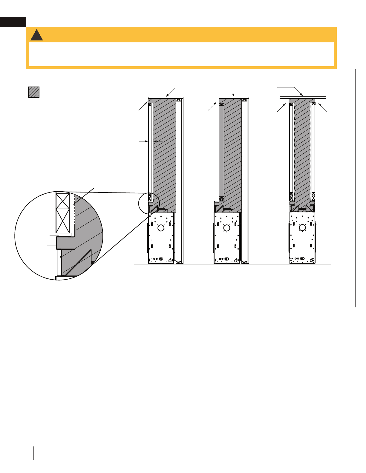
2.0 installation planning
installation planning
WARNING
!
• Do NOT cover or place any items in the Dynamic Heat Control™ air outlet. Failure to comply with these instructions will
create a fire hazard.
• Ensure air flow within the air passage is not restricted in any way with the exception of approved venting.
No materials of any type
are permitted in this area
Stud
Standoff
Upper
Frame
Dynamic
Heat Con-
trol™ air
outlet opening
Combustible
studding MUST
not be used past
the dotted line
3”
enclosure top and/or ceiling
Dynamic
Heat Con-
trol™ air
outlet opening
Dynamic
Heat Con-
trol™ air
outlet opening
Dynamic
Heat Con-
trol™ air
outlet opening
Single-Sided
Single-Sided
See-thru
(Recessed)*
*Restrictions also apply to see-thru when one or more recess is used.
Air flow in the shaded area must not be restricted in any way with the exception of an approved appliance vent system.
No other items are allowed in this area
Shaded framing must use non-combustible materials. No combustible materials allowed in this area or the space
between studs (i.e. no wiring, conduits, electrical bores, combustible framing members, etc.)
4
W415-1739 / C / 08.03.17
installation planning
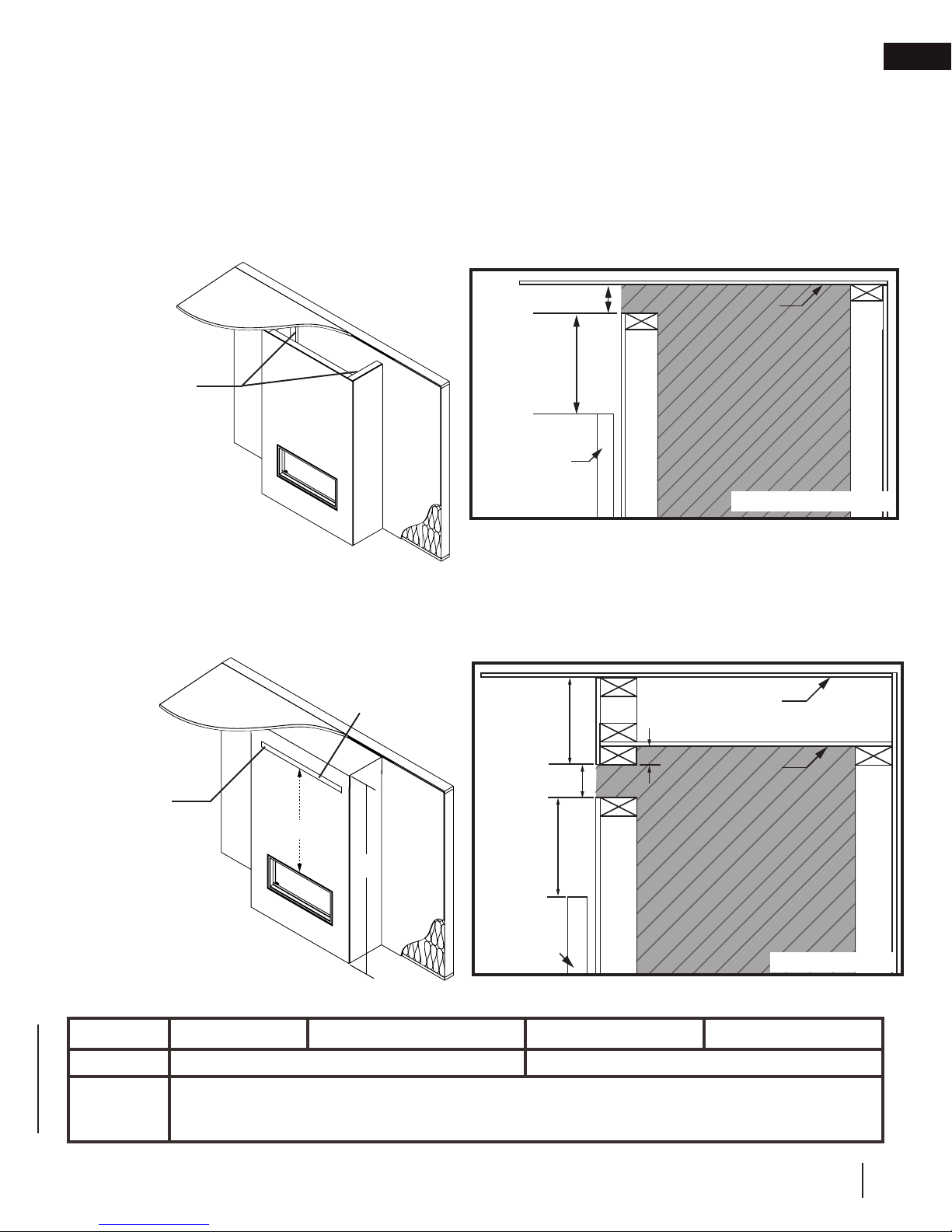
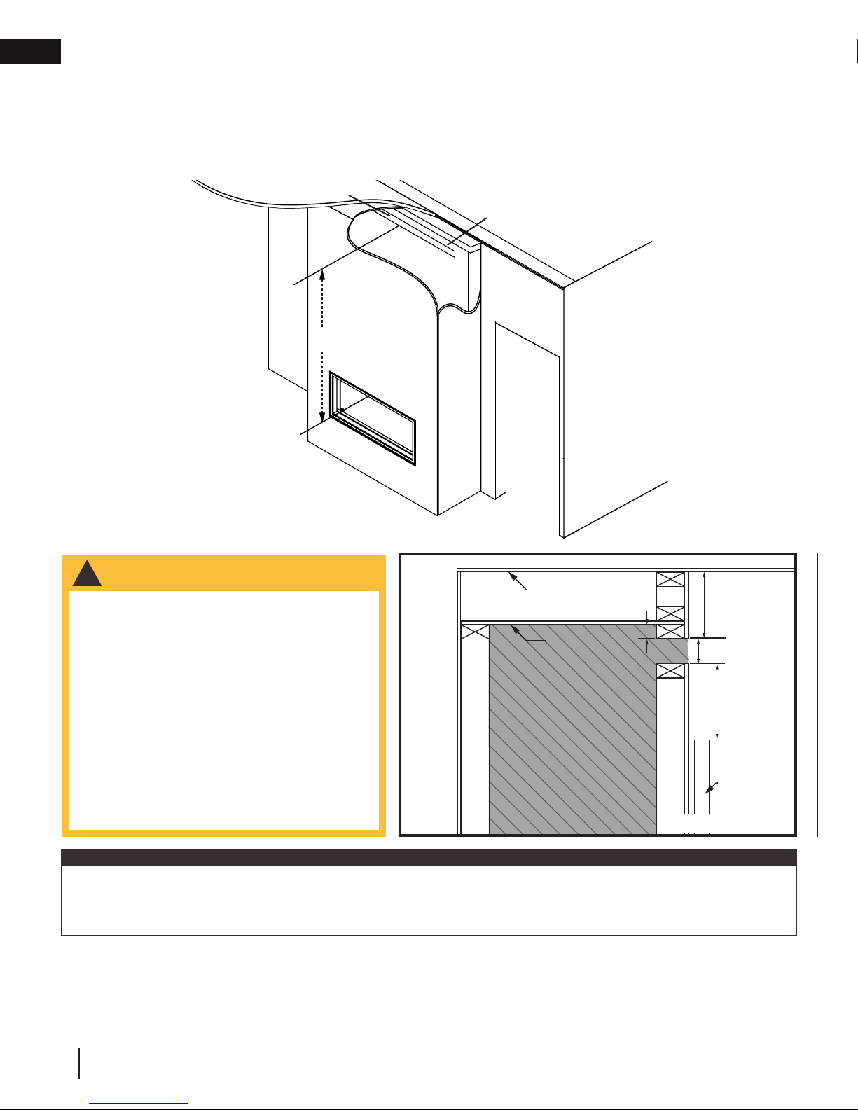
2.1 installation option 1 - open enclosure (enclosure stops short of the ceiling)
NOT Suitable for Dynamic Heat Control™ Plus
It is one option not to finish or close in the top of the enclosure to provide the necessary air circulation path for the
Dynamic Heat Control™ system. Leaving a complete air outlet opening above the enclosure has been found to
be well accepted with respect to final appearance and offer minimal distraction. It also allows for efficient circulation
of air within the room. This option offers the simplest method for framing and installation. (If installing Dynamic Heat
Control™ Plus, refer to option 2 or 3 - DHC Plus cannot be used with option 1). Limit the air outlet opening
height to 4” to reduce the risk of items inadvertly falling into the enclosure. The air outlet opening must extend
around the entire perimeter, or the entire front face of the enclosure, where the enclosure runs from wall
to wall.
EN
DYNAMIC HEAT
CONTROL™ AIR
OUTLET OPENING IS HOT WHEN
APPLIANCE IS
OPERATING!
Air outlet opening
must be located out of reach of
the user. Air outlet must not be
restricted by furnishings or decor.
2-4”
6” min
Wall mounted
object (picture
frame, appli-
ance, etc.)
ceiling
RECOMMENDED
2.2 installation option 2 - front opening
Suitable for Dynamic Heat Control™ Plus
Minimum air outlet opening dimensions must be followed. The opening is required to be framed no more than 1.5” below the
enclosure top (see option 2 diagram) to avoid trapping heat in the upper areas and the air outlet opening centered on the appliance
center. Framing the air outlet opening lower will overheat the appliance, the enclosure, and finishing material.
(Q x R)*
DYNAMIC HEAT
CONTROL™ AIR
OUTLET OPENING IS HOT WHEN
APPLIANCE IS
OPERATING!
S
L
Front air outlet opening must
be located out of reach of the
user. Air outlet must not be
restricted by furnishings or
decor.
Air outlet opening is required to be centered with the appliance.
MINIMUM AIR OUTLET OPENING DIMENSIONS
2 1/2”
min
2-3”
6” min
Wall mounted
object (picture
frame, appli-
ance, etc.)
0-1.5” Max
ceiling
enclosure top
must be installed
ALTERNATIVE
LVX38 LVX50 LVX62 LVX74
(Q x R)* 80 sq. in. minimum (Q must be 2-3”) 160 sq. in. minimum (Q must be 2-3”)
S
*Free area. Any trim edging or finishing must not reduce or restrict minimum area. Grills, grates, louvres, or
other unapproved covers are not permitted and will cause a fire hazard.
This dimension is determined from the enclosure height (L) minus the distance to the top of the Dynamic
Heat Control™ air outlet opening (0”-1.5”), height of the air opening (2”-3”), and the distance from the
base of the appliance to the top of the appliance viewing area (25 11/16”).
W415-1739 / C / 08.03.17
5
EN
installation planning
2.3 installation option 3 - rear opening
Suitable for Dynamic Heat Control™ Plus
Minimum air outlet opening dimension must be followed. The opening is required to be framed no more than 1.5” below the
enclosure top (see option 3 diagram) to avoid trapping heat in the upper areas and centered on the appliance center. Framing
the rear opening lower will overheat the appliance, the enclosure, and finishing material.
(Q x R)*
Dynamic Heat
Control™ rear air
outlet opening must
be located out of
reach of the user.
Opening must not
be restricted by furnishings or decor.
Air outlet opening is required to be centered with the appliance.
WARNING
!
S
Room 1
• When using a rear air outlet opening,
it is critical that the adjoining room or
living spaces are in direct air communication (i.e. of an open plan configuration
or connected by a permanently open
doorway or archway). This prevents
the appliance from being in a negative
pressure more than that of the adjoining
room. Failure to follow these requirements can result in reversing the Dynamic Heat Control™ air flow and will
cause the appliance, safety barrier, and
finishing materials to overheat, creating
a fire hazard.
Access
Side of
fireplace
AIR OUTLET
OPENING IS HOT
WHEN APPLIANCE
IS OPERATING!
ceiling
0-1.5” Max
enclosure top
must be installed
Room 2
2 1/2”
min
Other
room
2-3”
6” min
Wall mounted
object (picture
frame, appli-
ance, etc.)
ALTERNATIVE
note:
Increasing the air outlet opening will allow the appliance, the glass barrier (if equipped), the temperatures on the surfaces above the fireplace opening, and the enclosure be at cooler temperatures. It will also allow the air to circulate more effectively in the room. However,
if the appliance is equipped with the Dynamic Heat Control™ Plus, then the opening size must be 80 sq. in. for models
LV38-1, LV50-2, LVX38, and LVX50, or 160 sq. in. for models LV62, LV74, LVX62, and LVX74.
6
W415-1739 / C / 08.03.17
installation planning
note:
See-thru appliances require front or rear air outlet opening. If desired, it can be installed with both front and rear air outlet openings
to allow heat to circulate in two rooms however it is recommended to install the air outlet opening at different heights that meet the
installation parameters for aesthetic purposes. For Dynamic Heat Control™ plus, a second opening MUST NOT be installed
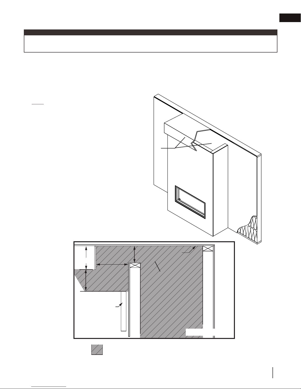
2.4 installation option 4 - open enclosure with hard combustible valance
NOT Suitable for Dynamic Heat Control™ Plus
is similar to option 1 with the addition of a hard combustible valance. Minimum opening dimensions and valance dimensions
must be followed (See option 4 diagram). Restricting air movement within the valance area will overheat the appliance,
the enclosure, and finishing material.
NOTE: Air outlet opening must be at least continuous
around the top of the enclosure for a valance to be permitted. Using the minimum air outlet opening from option 1 or 2
is not permitted and will overheat the appliance.
DYNAMIC HEAT
CONTROL™ AIR
OUTLET OPENING IS HOT WHEN
APPLIANCE IS
OPERATING!
EN
Air outlet opening must be located out of reach of the user.
Air outlet must not be restricted by furnishings or decor.
6” Max.
6” Min.
6” Min.
Wall mounted object
(picture frame, appli-
ance, etc.)
ABSOLUTELY NO OBSTRUCTION OR RESTRICTION ALLOWED IN THE ENTIRE SHADED AREA WITH THE EXCEPTION OF APPROVED VENTING
4” min
ceiling
air outlet opening
must be continuous
around enclosure top.
ALTERNATIVE
W415-1739 / C / 08.03.17
7
EN
installation planning
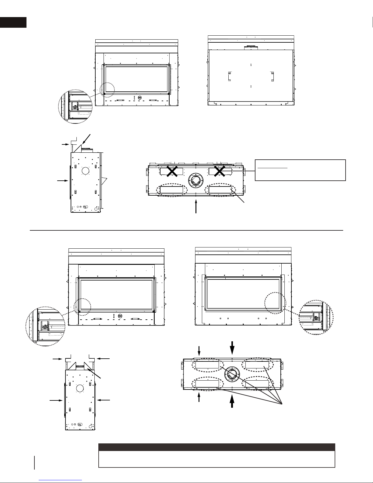
3.0 appliance overview
SINGLE-SIDED INSTALLATION
pilot location
deflectors shown after installation
front frame
access
side
access side
side view
SEE-THRU INSTALLATION
(frame and deflectors not shown)
top view
For knockout plate removal
access side
(access side only), see “DHC
install” section.
fixed side
WARNING: DO NOT REMOVE
FROM FIXED SIDE
pilot location
front frame
access side
8
W415-1739 / C / 08.03.17
access side
side view
pilot location
rear frame
deflectors
shown after
installation
fixed side
pilot location
from viewing
area
pilot location
from viewing
area
fixed side
fixed side
access side
For knockout plate removal (both sides),
see “DHC install” section.
top view
(frame and deflectors not shown)
note:
To determine which side is the access side, the pilot should be located in the left side of
the firebox from the viewing area when the appliance is viewed from the access side.

4.0 Dynamic Heat Control™ installation
access side
access side
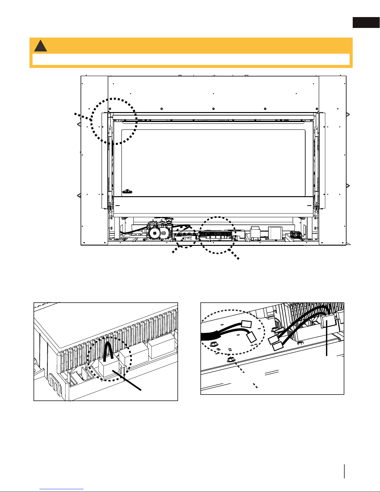
Before starting the Dynamic Heat Control™ installation, remove safety barrier. Refer to “safety barrier installation/
removal” section in the installation manual
SINGLE-SIDED SHOWN
Front Frame
Dynamic Heat Control™ installation
EN
1.) Remove fasteners securing front frame (and rear
frame for see-thru). Do not discard fasteners.
SINGLE-SIDED SHOWN
2.) Remove knockouts plates (FOR SINGLE-SIDED, ONLY REMOVE
THE TWO KNOCKOUTS PLATES ON THE ACCESS SIDE). Discard
knockout plates. Recommended: Use a flathead screwdriver or a
small pry bar and use prying motion to remove the knockout. Use
a brace such as a piece of wood under the prying tool to avoid distorting
the top
COVER PLATE
Cover Plate
3.) Remove the fasteners securing the cover plates recessed below the knockout plates. For ease of removal, lift the panel from below in
front of the firebox door. Discard cover plates.
IMPORTANT:
Fire Hazard Warning: This step is crucial for your appliance to work properly. If
the knockout plates AND the cover plates are not removed from the viewed side,
the appliance will overheat, the barrier will become excessively hot, and the high
limit switch will constantly trip.
W415-1739 / C / 08.03.17
9
EN
Dynamic Heat Control™ installation
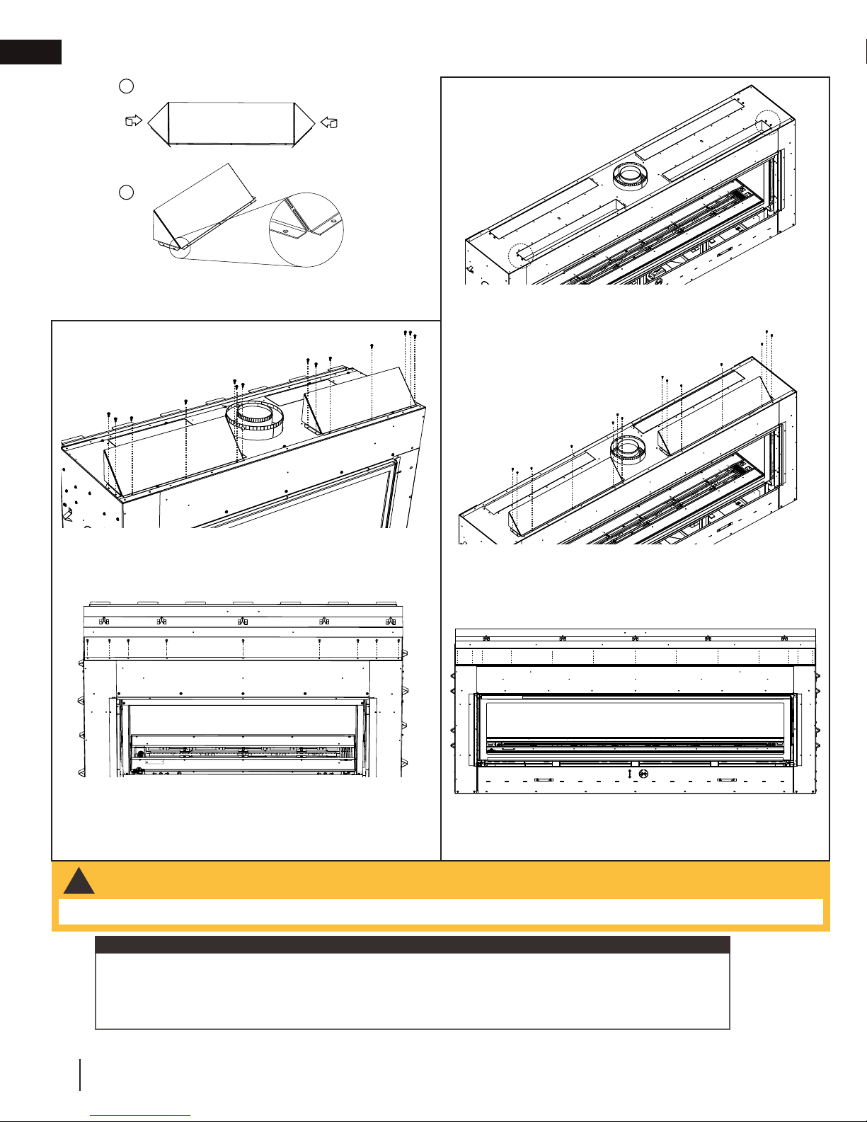
a
b
4.) Bend the sides of the deflectors as shown.
FOR LV38-1 / LV62
FOR LV50-2 / LV74
5.) Remove outer knockout fasteners. Do not discard
fasteners.
5.) Secure deflectors to the appliance with supplied fasteners as
shown.
6.) Re-install front frame using the fasteners removed in step 1.
WARNING
!
6.) Secure deflectors to the appliance with fasteners removed in
step 5 and supplied fasteners.
7.) Re-install front frame using the fasteners previously used
in step 1.
• FOR SEE-THRU APPLIANCES, REPEAT STEPS WITH THE FIXED SIDE.
IMPORTANT:
It is recommended to install venting and vent heat shield(s) before refitting the
front, (and where applicable rear), frame for ease of access. It is critical for see-thru
appliances that ALL 4 knockout plates, ALL 4 cover plates are removed and ALL 4
deflectors are installed.
10
W415-1739 / C / 08.03.17
Dynamic Heat Control™ installation
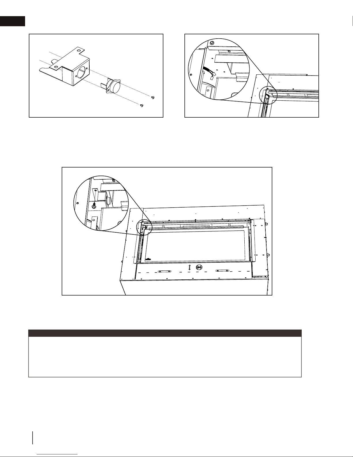
4.1 high limit switch installation
WARNING
!
• High Limit Switch installation is MANDATORY. Failure to correctly install will cause a fire hazard.
Bracket Install
Location
access side
EN
Wire Harness
“X4”
1.) Remove jumper plug from control board (marked “X4”)
and install plug with spade connectors to the control
board. Discard the original jumper plug.
Control Board
Plug with spade
connectors
Wire Harness
W415-1739 / C / 08.03.17
11
EN
Dynamic Heat Control™ installation
3.) Insert the high limit switch into the bracket and secure
with two fasteners (supplied).
4.) Locate the existing wire harness in the upper left corner
of the firebox as shown. Connect wires to the high limit
switch.
access side
5.) Install high limit switch assembly to the bracket install location in the upper left hand corner of the
appliance. Secure high limit switch assembly with a supplied screw as shown.
IMPORTANT:
After installing the Dynamic Heat Control™ Kit, ensure appliance is clean from dust, debris, etc.
before continuing with the appliance installation. Take precautions to ensure framing or finishing
dust and debris does not enter the air outlet openings or deflectors.
Check and clean appliance before operation.
Re-install safety barrier. “Refer to safety barrier installation / removal” in the installation manual.
12
W415-1739 / C / 08.03.17
Dynamic Heat Control™ installation
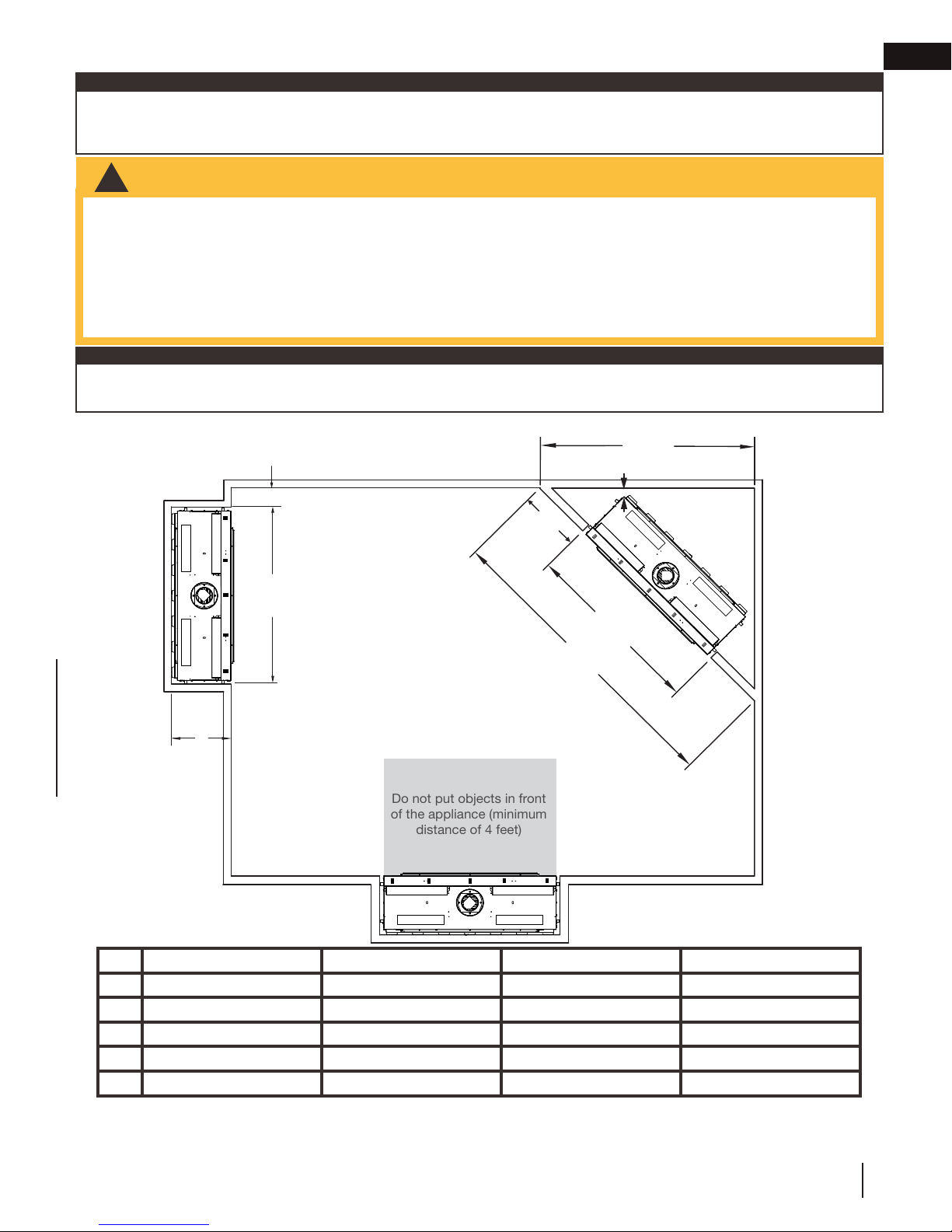
!
WARNING
Do not put objects in front
of the appliance (minimum
distance of 4 feet)
5.0 minimum framing dimensions
note:
When using optional finishing accessories, the framing dimensions and finishing materials may differ from what is outlined in the section below; refer to the leaflet instructions supplied in the accessory kit for specific framing and finishing
specifications.
• Risk of fire!
• In order to avoid the possibility of exposed insulation or vapour barrier coming in contact with the appliance body, it is
recommended that the walls of the appliance enclosure be “finished” (i.e. drywall / sheetrock), as you would finish any
other outside wall of a home. This will ensure that clearance to combustibles is maintained within the cavity.
• Do not notch the framing around the appliance stand offs. Failure to maintain air space clearance may cause over heating
and fire. Prevent contact with sagging or loose insulation or framing and other combustible materials. Block opening into
the chase to prevent entry of blown-in insulation. Make sure insulation and other materials are secured.
• Minimum clearance to combustibles must be maintained or a serious fire hazard could result.
note:
For heavier finishing materials such as marble, we recommend adding extra support to the frame. Ensure there is
adequate floor support for the appliance and finishing material.
EN
minimum framing dimensions
6” (15.2cm) min.
F
E
G
1” (2.54cm) min.
H
F
I
LV38-1 LV50-2 LV62 LV74
E
F
G
H
I
20 1/8” (51.1cm) 20 1/8” (51.1cm) 20 1/8” (51.1cm) 20 1/8” (51.1cm)
53 13/16” (136.7cm) 65 13/16” (167.2cm) 77 13/16” (197.6cm) 89 13/16” (228.1cm)
63 3/4” (162cm) 72 1/4” (183.5cm) 80 11/16” (205cm) 89 1/4” (226.6cm )
18 3/16” (46.2cm) 18 3/16” (46.2cm) 18 3/16” (46.2cm) 18 3/16” (46.2cm)
90 3/16” (229cm) 102 3/16” (259.5cm) 114 1/8” (289.9cm) 126 1/8” (320.4cm)
W415-1739 / C / 08.03.17
13
EN
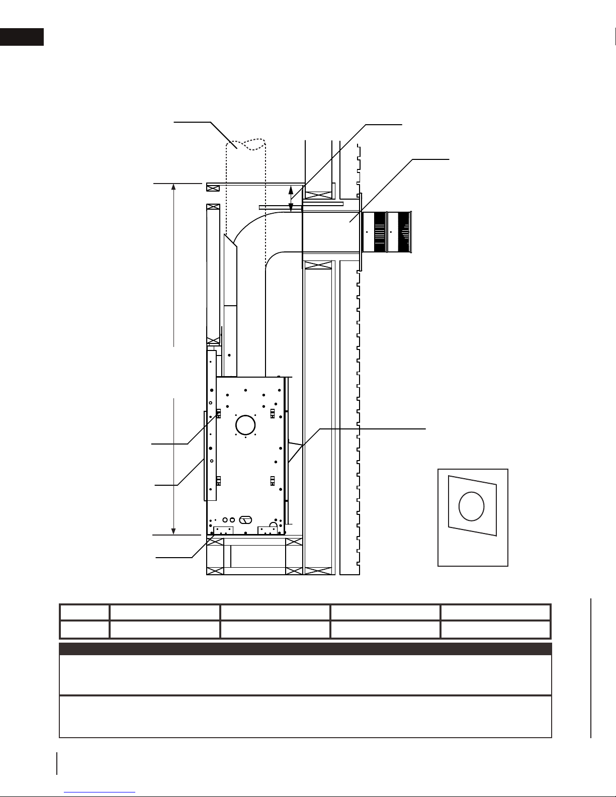
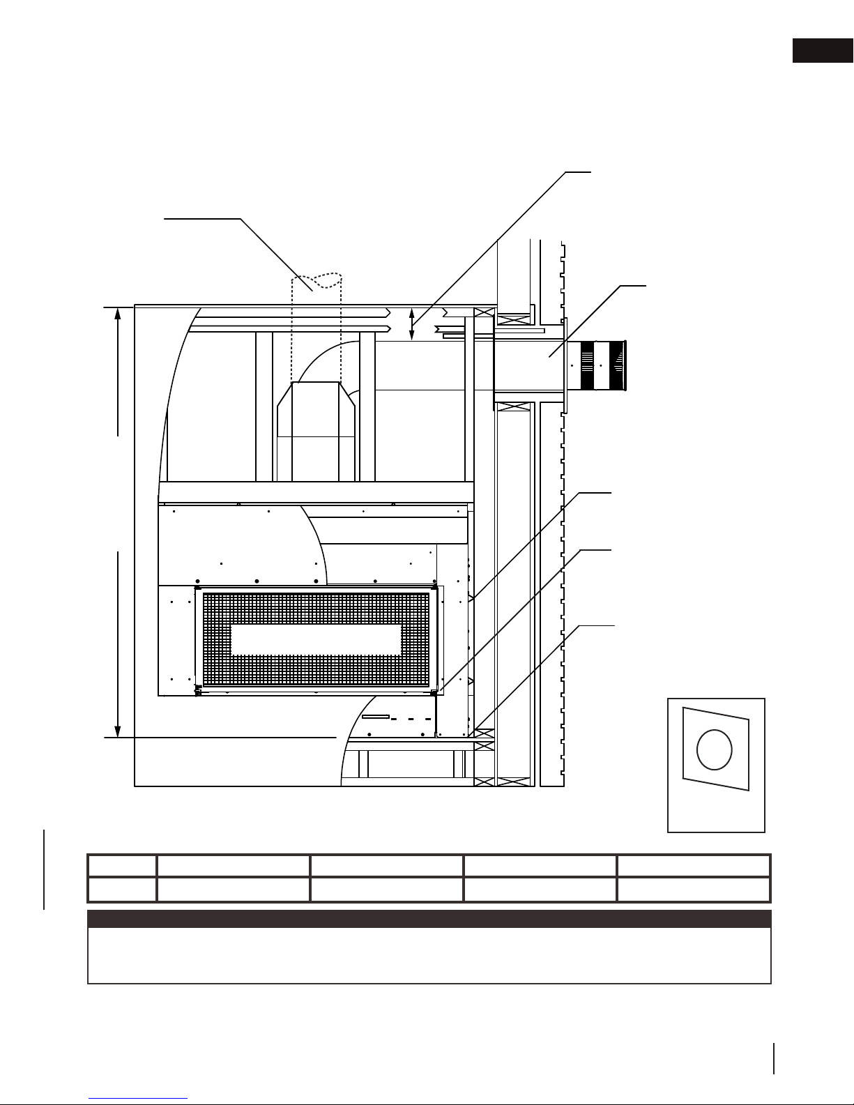
minimum clearance to combustible enclosures6.0 minimum clearance to combustible enclosures
single-sided
1” [25mm] minimum
to sides for vertical
venting.
When passing through
a ceiling, use firestop
spacer W500-0028
(not supplied)
6” [152mm] minimum
3” [76mm] to top
2” [51mm] to sides /
bottom
When passing through
a wall, use firestop
spacer assembly
W010-4178 (supplied)
0” to non-combustible
finishing such as brick
and stone. When using
non-combustible finishing, only use firestop
spacer (W615-0162)
included in the firestop
assembly (W010-4178)
L
0” to back standoffs
0” to side standoffs
1/2” finishing flange
0” to bottom of the
appliance
firestop spacer
(W615-0162)
minimum clearance
Ref LV38-1 LV50-2 LV62 LV74
L
note:
The LV series requires a minimum inside enclosure height of 73” measured from the bottom of the appliance.
For temperature requirements, this area must be left unobstructed. It is mandatory to ventilate the enclosure
according to these instructions.
73” (185.4cm) 73” (185.4cm) 91” (231.1cm) 91” (231.1cm)
Although the minimum enclosure height for the LV series is 73”, some venting configurations that require more
vertical rise will require a larger enclosure to provide minimum vertical clearance between vent pipes and combustibles.
14
W415-1739 / C / 08.03.17
see-thru
1” [25mm]
minimum to
sides for vertical
venting.
When passing
through a
ceiling, use
firestop spacer
W500-0028 (not
supplied)
minimum clearance to combustible enclosures
6” [152mm] minimum
3” [76mm] to top
2” [51mm] to sides /
bottom
When passing through
a wall, use firestop
spacer assembly
W010-4178 (supplied)
0” to non-combustible
finishing such as brick
and stone. When using
non-combustible finishing, only use firestop
spacer (W615-0162)
included in the firestop
assembly (W010-4178)
EN
L
SAFETY BARRIER
0” to side standoffs
1/2” finishing flange
(4 sides)
0” to base of the
appliance
minimum clearance
Ref LV38-1 LV50-2 LV62 LV74
L
73” (185.4cm) 73” (185.4cm) 91” (231.1cm) 91” (231.1cm)
firestop spacer
(W615-0162)
note:
Although the minimum enclosure height for the LV series is 73”, some venting configurations that require more
vertical rise will require a larger enclosure to provide minimum vertical clearance between vent pipes and combustibles.
W415-1739 / C / 08.03.17
15
EN
finish framing - after appliance installation
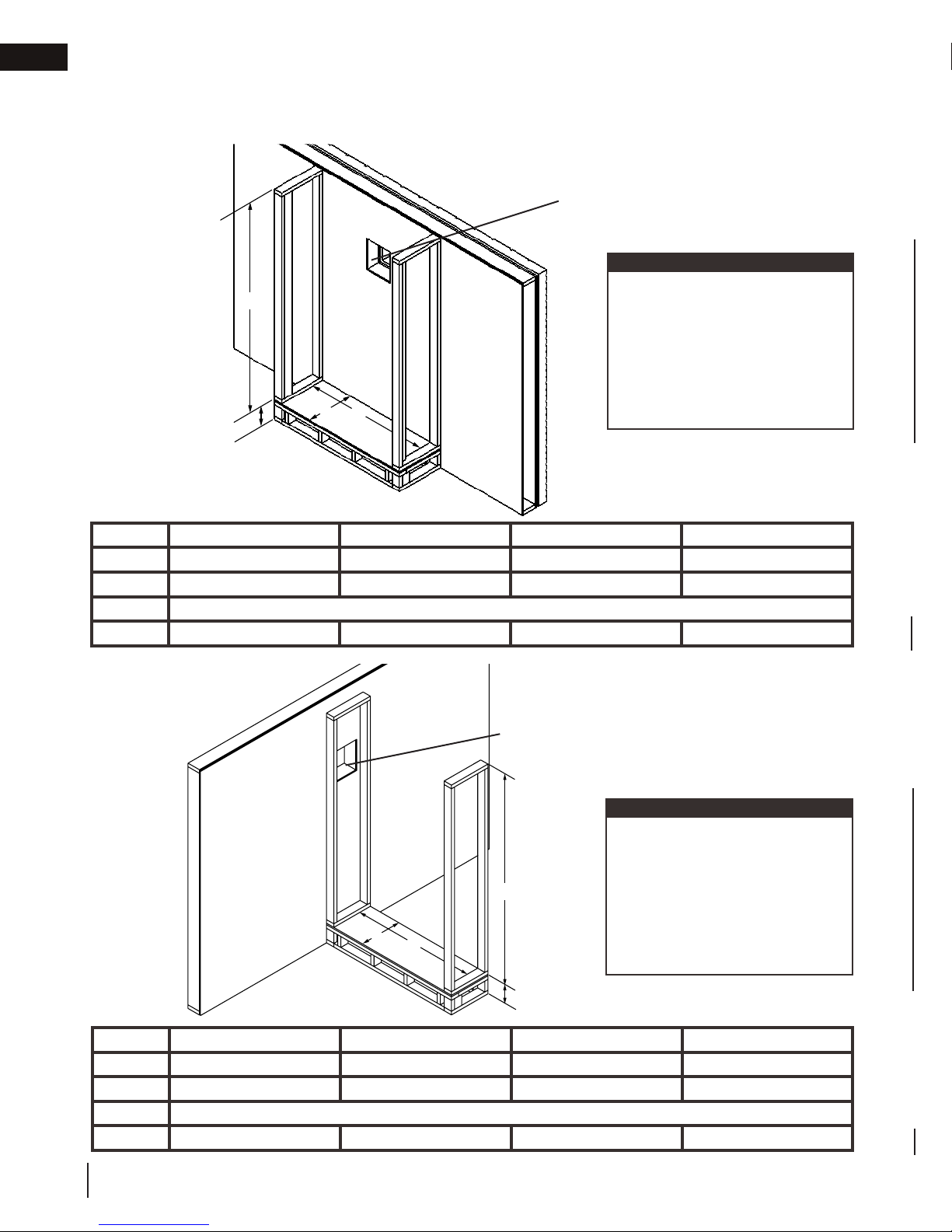
7.0 rough framing - before appliance installation
Before framing your appliance, determine vent requirements before deciding the final location of the appliance.
After rough framing, place the appliance in its final position. Also, see appliance manual for vent shield installation,
nailing tabs installation,electrical installation, gas installation, etc.
single-sided
Before framing the appliance, ensure to install
the firestop first as it will not fit between the
studs if installed after framing.
note:
Although the minimum enclosure
L
height for the LV series is 73”,
some venting configurations
that require more vertical rise
will require a larger enclosure to
provide minimum vertical clearance between vent pipes and
E
J
F
combustibles.
Ref LV38-1 LV50-2 LV62 LV74
E
F
J
L
20 1/8” (51.1cm) 20 1/8” (51.1cm) 20 1/8” (51.1cm) 20 1/8” (51.1cm)
53 13/16” (136.7cm) 65 13/16” (167.2cm) 77 13/16” (197.6cm) 89 13/16” (228.1cm)
Optional - Appliance does not need to be elevated above floor
73” (185.4cm) 73” (185.4cm) 91” (231.1cm) 91” (231.1cm)
see-thru
Before framing the appliance, ensure to install
the firestop first as it will not fit between the
studs if installed after framing.
note:
Although the minimum enclosure height for the LV series is
73”, some venting configurations
L
E
F
that require more vertical rise will
require a larger enclosure to provide minimum vertical clearance
between vent pipes and combustibles.
Ref LV38-1 LV50-2 LV62 LV74
E
F
J
L
16
W415-1739 / C / 08.03.17
16 3/16” (41.1cm) 16 3/16” (41.1cm) 16 3/16” (41.1cm) 16 3/16” (41.1cm)
53 13/16” (136.7cm) 65 13/16” (167.2cm) 77 13/16” (197.6cm) 89 13/16” (228.1cm)
73” (185.4cm) 73” (185.4cm) 91” (231.1cm) 91” (231.1cm)
J
Optional - Appliance does not need to be elevated above floor
 Loading...