

Page 1
INSTALLER: LEAVE THIS MANUAL WITH THE APPLIANCE.
CONSUMER: RETAIN THIS MANUAL FOR FUTURE REFERENCE.
NEVER LEAVE CHILDREN OR OTHER AT RISK INDIVIDUALS ALONE WITH THE APPLIANCE.
INSTALLATION AND
EN
OPERATING INSTRUCTIONS
CONFORMS TO AMERICAN NATIONAL STANDARDS: ANSI Z21.50, CERTIFIED TO CANADIAN CSA 2.22 FOR VENTED GAS FIREPLACES.
CERTIFIED FOR CANADA AND UNITED STATES USING ANSI/CSA METHODS.
SAFETY INFORMATION
!
WARNING
If the information in these instructions
are not followed exactly, a fi re or
explosion may result causing property
damage, personal injury or loss of life.
- Do not store or use gasoline or other fl ammable
vapors and liquids in the vicinity of this or any
other appliance.
- WHAT TO DO IF YOU SMELL GAS:
• Do not try to light any appliance.
• Do not touch any electrical switch; do not use
any phone in your building.
• Immediately call your gas supplier from a
neighbour’s phone. Follow the gas supplier’s
instructions.
• If you cannot reach your gas supplier, call the
fi re department.
- Installation and service must be performed by a
qualifi ed installer, service agency or the supplier.
This appliance may be installed in an aftermarket,
permanently located, manufactured home (USA
only) or mobile home, where not prohibited by
local codes.
This appliance is only for use with the type of gas
indicated on the rating plate. This appliance is
not convertible for use with other gases, unless a
certifi ed kit is used.
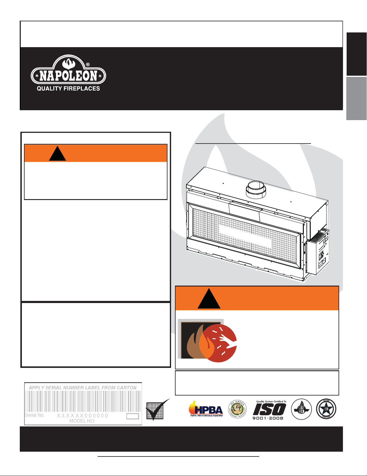
LHD62N
NATURAL GAS
LHD62P
PROPANE
SAFETY BARRIER
!
WARNING
HOT GLASS WILL CAUSE
BURNS.
DO NOT TOUCH GLASS UNTIL
COOLED.
NEVER ALLOW CHILDREN TO
TOUCH GLASS.
FR
PG
63
Decorative Product: Not for use as a heating appliance.
Wolf Steel Ltd., 24 Napoleon Rd., Barrie, ON, L4M 0G8 Canada /
103 Miller Drive, Crittenden, Kentucky, USA, 41030
Phone (705)721-1212 • Fax (705)722-6031 • www.napoleonfi replaces.com • ask@napoleonproducts.com
$10.00
A barrier designed to reduce the risk of burns from the
hot viewing glass is provided with the appliance and
shall be installed.
BARRIER
1.36D
CERTIFIED
W415-1334 / 06.10.14
Page 2

2
EN
W415-1334 / 06.10.14
TABLE OF CONTENTS
NOTE: The camera icon indicates video tutorials are available as additional reference, visit http://
www.napoleonfi replaces.com/category/product-support/support-centre/
1.0 INSTALLATION OVERVIEW 3
2.0 INTRODUCTION 4
2.1 DIMENSIONS 5
2.2 GENERAL INSTRUCTIONS 6
2.3 GENERAL INFORMATION 7
2.4 RATING PLATE / LIGHTING INSTRUCTION LOCATION 8
2.5 SHIPPING HANDLES 9
3.0 VENTING 9
3.1 VENTING LENGTHS AND COMPONENTS FOR DIRECT VENT INSTALLATIONS 10
3.2 TYPICAL VENT INSTALLATIONS 11
3.3 MINIMUM AIR TERMINAL LOCATION CLEARANCES 12
3.4 VENT APPLICATION FLOW CHART 13
3.5 DEFINITIONS 13
3.6 ELBOW VENT LENGTH VALUES 13
3.7 HORIZONTAL TERMINATION 14
3.8 VERTICAL TERMINATION 16
4.0 INSTALLATION 18
4.1 WALL AND CEILING PROTECTION 18
4.1.1 HORIZONTAL INSTALLATION 19
4.1.2 VERTICAL INSTALLATION 19
4.2 USING FLEXIBLE VENT COMPONENTS 20
4.2.1 HORIZONTAL AIR TERMINAL INSTALLATION 20
4.2.2 VERTICAL AIR TERMINAL INSTALLATION 21
4.2.3 APPLIANCE VENT CONNECTION 22
4.3 MOBILE HOME INSTALLATION 22
4.4 GAS INSTALLATION 23
5.0 FRAMING 24
5.1 MINIMUM CLEARANCE TO COMBUSTIBLE ENCLOSURES 28
5.2 INSTALLING NON-COMBUSTIBLE BOARD 30
5.3 NON-COMBUSTIBLE FINISH MATERIAL 31
5.5 MINIMUM COMBUSTIBLE MANTEL CLEARANCES 32
6.0 FINISHING 33
6.1 SAFETY SCREEN AND DOOR REMOVAL / INSTALLATION 33
6.2 GLASS MEDIA INSTALLATION 35
6.4 OPTIONAL ROCK PLACEMENT 36
6.5 LOGO PLACEMENT 36
7.0 ELECTRICAL CONNECTION 36
7.1 HARD WIRING CONNECTION 36
7.2 RECEPTACLE WIRING DIAGRAM 37
7.3 BATTERY HOLDER INSTALLATION 37
7.4 SCHEMATIC 38
8.0 OPERATION 39
8.1 GENERAL TRANSMITTER LAYOUT 39
8.2 INITIALIZING THE TRANSMITTER/BATTERY HOLDER FOR THE FIRST TIME 39
8.3 TEMPERATURE DISPLAY 40
8.4 FLAME HEIGHT 40
8.5 NIGHT LIGHT DIMMER CONTROL 40
8.6 CONTINUOUS PILOT / INTERMITTENT PILOT (CPI / IPI) SELECTION 41
8.7 KEY LOCK 41
8.8 LOW BATTERY / MANUAL BYPASS 41
9.0 OPERATING INSTRUCTIONS 42
10.0 ADJUSTMENT 43
10.1 RESTRICTING VERTICAL VENTS 43
10.2 PILOT BURNER ADJUSTMENT 43
10.3 VENTURI ACCESS 43
10.4 VENTURI ADJUSTMENT 44
10.5 FLAME CHARACTERISTICS 44
11.0 MAINTENANCE 45
11.1 ANNUAL MAINTENANCE 45
11.2 CONTROL ACCESS 46
11.3 MEDIA REMOVAL/REPLACEMENT 46
11.4 BURNER REMOVAL 47
11.5 BURNER ASSEMBLY REMOVAL 47
11.6 NIGHT LIGHT REPLACEMENT 48
11.8 DOOR LATCH REPLACEMENT 48
11.7 PORCELAIN PANEL REMOVAL 48
11.9 GLASS / DOOR REPLACEMENT 49
11.10 CARE OF GLASS 49
11.11 CARE OF PLATED PARTS 49
12.0 REPLACEMENTS 50
13.0 OVERVIEW 51
14.0 VALVE TRAIN ASSEMBLY 52
15.0 BURNER ASSEMBLY 53
16.0 ACCESSORIES 54
17.0 VENTING 56
18.0 TROUBLESHOOTING 57
19.0 WARRANTY 60
20.0 SERVICE HISTORY 61
NOTE: Changes, other than editorial, are denoted by a vertical line in the margin.
Page 3
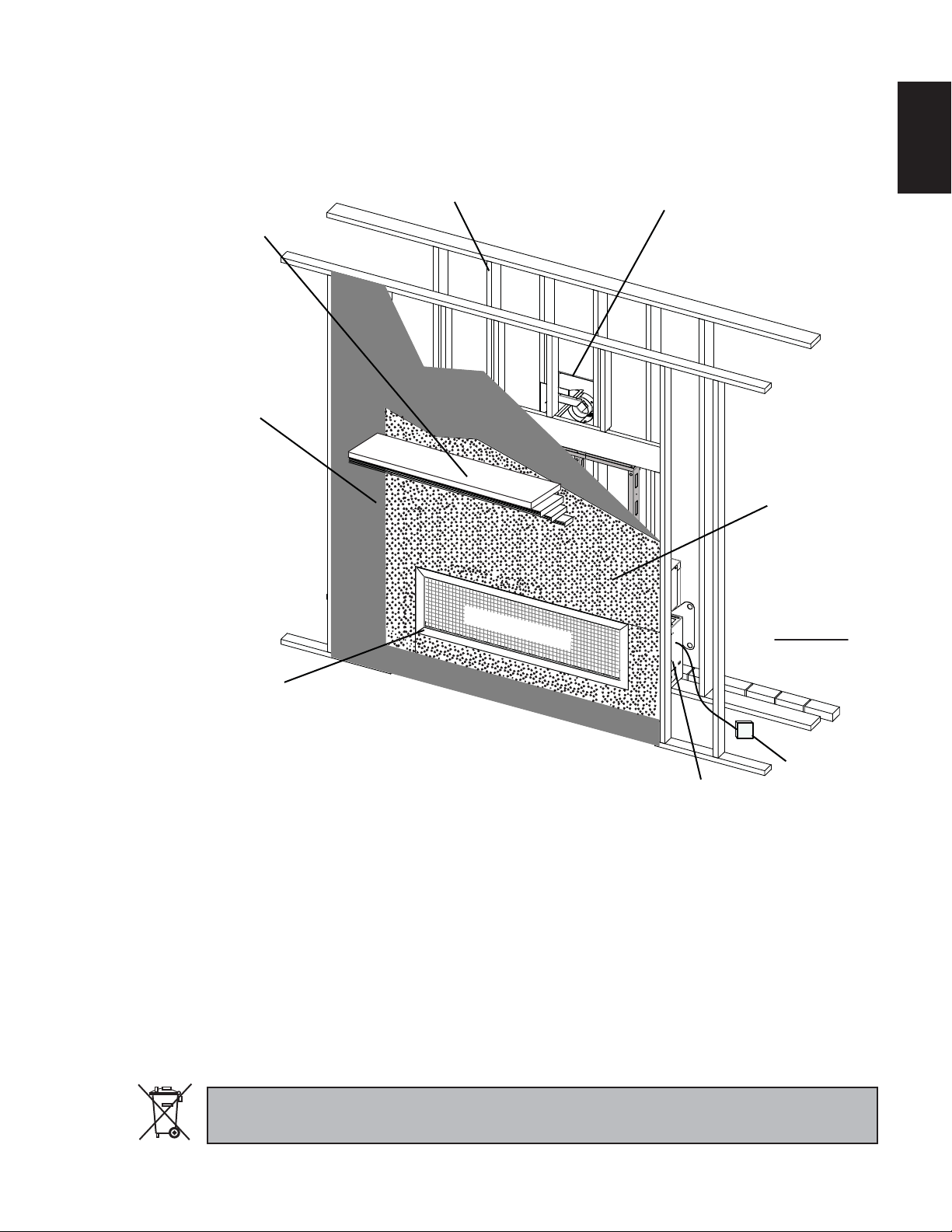
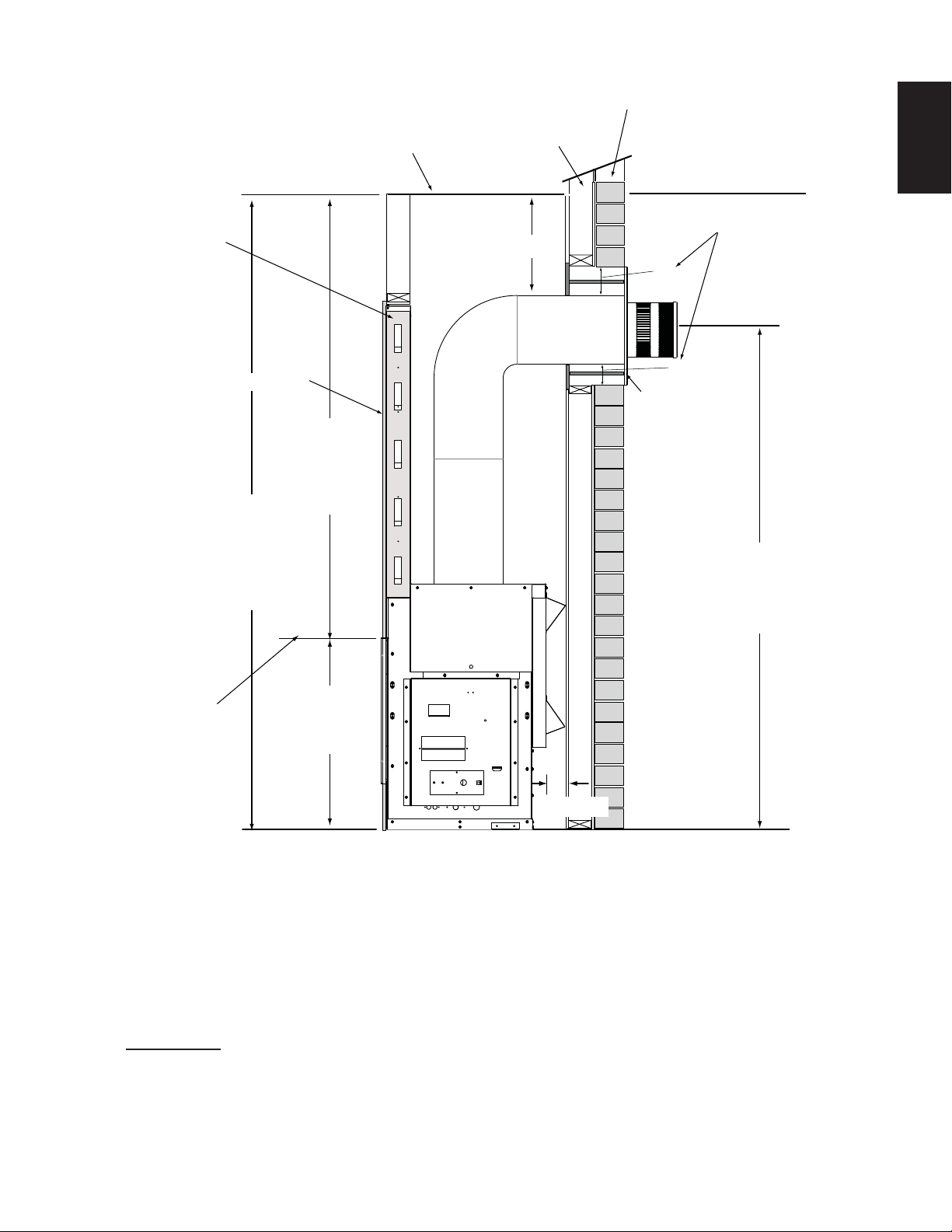
1.0 INSTALLATION OVERVIEW
3
See the section
“FRAMING MINIMUM
MANTEL
CLEARANCES”
See the section
“FRAMING MINIMUM CLEARANCE TO
COMBUSTIBLE
ENCLOSURES” for
drywall (or other
combustible
material)”
See the section
“RATING PLATE / LIGHTING
INSTRUCTION LOCATION”
See the section
“FRAMING”
SAFETY BARRIER
See the section
“VENTING - VENTING
LENGTHS AND AIR TERMINAL
LOCATIONS”
See the section
“FRAMING MINIMUM
CLEARANCE
TO COMBUSTIBLE
ENCLOSURES”
for noncombustible
materials such
as tile, marble,
granite, etc.
Important: Extra
support may be
required
EN
See the section
“CONTROL ACCESS”
for the control box.
Batteries must be disposed of according to the local laws and regulations. Some batteries may be recycled,
and may be accepted for disposal at your local recycling center. Check with your municipality for recycling
instructions.
See the section
“BATTERY
HOLDER
W415-1334 / 06.10.14
”.
Page 4

4
2.0 INTRODUCTION
EN
• THIS APPLIANCE IS HOT WHEN OPERATED AND CAN CAUSE SEVERE BURNS IF CONTACTED.
• ANY CHANGES OR ALTERATIONS TO THIS APPLIANCE OR ITS CONTROLS CAN BE DANGEROUS AND IS
PROHIBITED.
• Do not operate appliance before reading and understanding operating instructions. Failure to operate appliance
according to operating instructions could cause fi re or injury.
• Risk of fi re or asphyxiation do not operate appliance with fi xed glass removed.
• Do not connect 110 volts to the control valve.
• Risk of burns. The appliance should be turned off and cooled before servicing.
• Do not install damaged, incomplete or substitute components.
• Risk of cuts and abrasions. Wear protective gloves and safety glasses during installation. Sheet metal edges may
be sharp.
• Do not burn wood or other materials in this appliance.
• Children and adults should be alerted to the hazards of high surface temperature and should stay away to
avoid burns or clothing ignition.
• Young children should be carefully supervised when they are in the same room as the appliance.
Toddlers, young children and others may be susceptible to accidental contact burns. A physical barrier
is recommended if there are at risk individuals in the house. To restrict access to an appliance, install an
adjustable safety gate to keep toddlers, young children and other at risk individuals out of the room and
away from hot surfaces.
• Clothing or other fl ammable material should not be placed on or near the appliance.
• Due to high temperatures, the appliance should be located out of traffi c and away from furniture and
draperies.
• Ensure you have incorporated adequate safety measure to protect infants/toddlers from touching hot surfaces.
• Even after the appliance is out, the glass and/or screen will remain hot for an extended period of time.
• Check with your local hearth specialty dealer for safety screens and hearth guards to protect children from hot
surfaces. These screens and guards must be fastened to the fl oor.
• Any safety screen, guard or barrier removed for servicing the appliance, must be replaced prior to operating
the appliance.
• The appliance is a vented gas-fi red appliance. Do not burn wood or other materials in the appliance
• It is imperative that the control compartments, burners and circulating blower and its passageway in the appliance
and venting system are kept clean. The appliance and its venting system should be inspected before use and at
least annually by a qualifi ed service person. More frequent cleaning may be required due to excessive lint from
carpeting, bedding material, etc. The appliance area must be kept clear and free from combustible materials,
gasoline and other fl ammable vapors and liquids.
• Under no circumstances should this appliance be modifi ed.
• This appliance must not be connected to a chimney fl ue pipe serving a separate solid fuel burning appliance.
• Do not use this appliance if any part has been under water. Immediately call a qualifi ed service technician to inspect
the appliance and to replace any part of the control system and any gas control which has been under water.
• Do not operate the appliance with the glass door removed, cracked or broken. Replacement of the glass should be
done by a licensed or qualifi ed service person.
• Do not strike or slam shut the appliance glass door.
• When equipped with pressure relief doors, they must be kept closed while the appliance is operating to prevent
exhaust fumes containing carbon monoxide, from entering into the home. Temperatures of the exhaust escaping
through these openings can also cause the surrounding combustible materials to overheat and catch fi re.
• Only doors / optional fronts certifi ed with the appliance are to be installed on the appliance.
• Keep the packaging material out of reach of children and dispose of the material in a safe manner. As with all plastic
bags, these are not toys and should be kept away from children and infants.
• As with any combustion appliance, we recommend having your appliance regularly inspected and serviced as well
as having a Carbon Monoxide Detector installed in the same area to defend you and your family against Carbon
Monoxide.
• Ensure clearances to combustibles are maintained when building a mantel or shelves above the appliance.
Elevated temperatures on the wall or in the air above the appliance can cause melting, discolouration or damage of
decorations, a T.V. or other electronic components.
• A barrier designed to reduce the risk of burns from the hot viewing glass is provided with this appliance and
shall be installed.
• If the barrier becomes damaged, the barrier shall be replaced with the manufacturer’s barrier for this
appliance.
• Installation and repair should be done by a qualifi ed service person. The appliance should be inspected
before use and at least annually by a professional service person. More frequent cleaning may be required
due to excessive lint from carpeting, bedding material, etc. It is imperative that control compartments,
burners and circulating air passageways of the appliance be kept clean.
!
WARNING
3.2C
W415-1334 / 06.10.14
Page 5
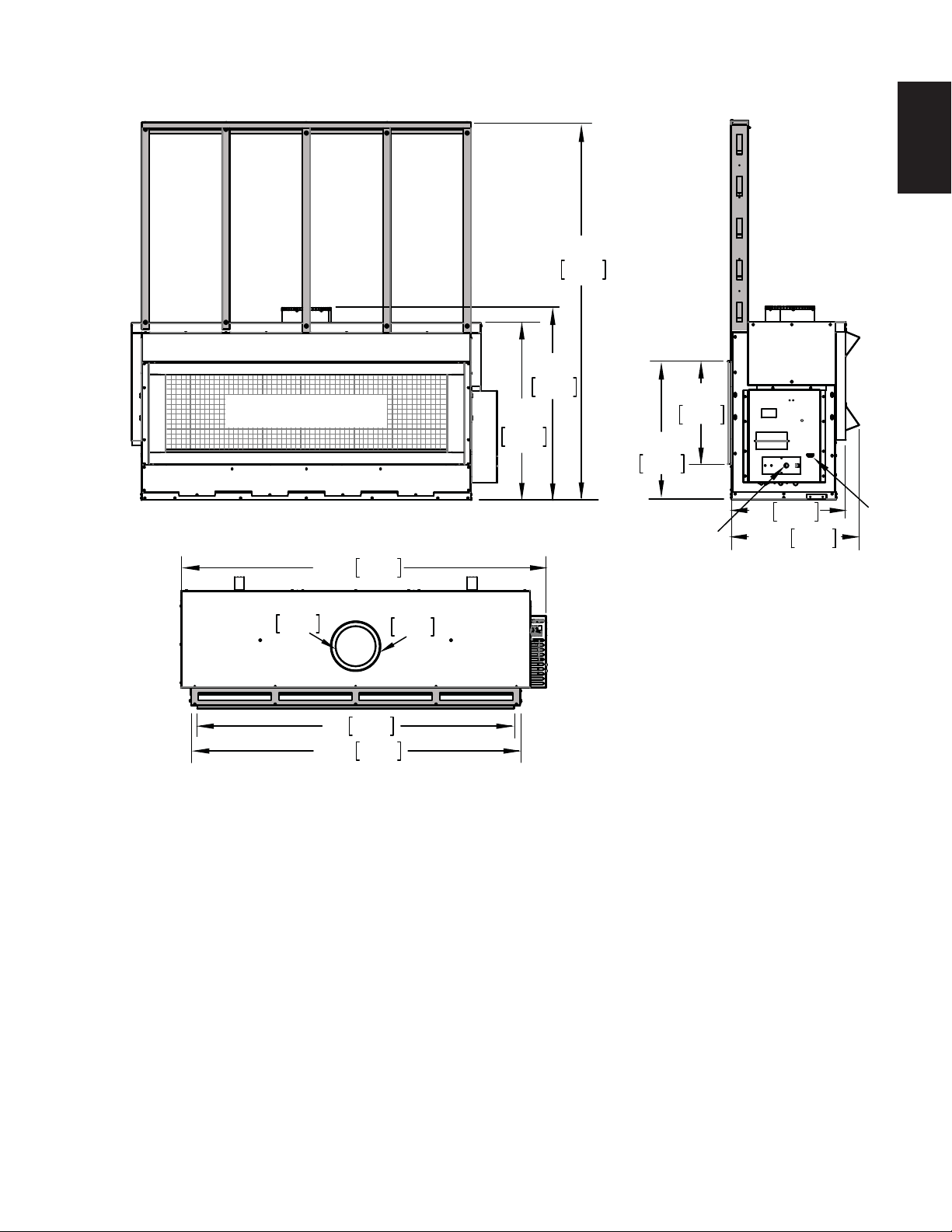
2.1 DIMENSIONS
SAFETY BARRIER
41”
1041mm
35 7/8"
911mm
5
EN
76 1/2”
1943mm
20 3/4"
527mm
27 7/8"
708mm
73 7/8”
Ø
8 "
203mm
66 1/2”
1873mm
1626mm
64”
1689mm
Ø
10 "
254mm
ELECTRICAL
INLET
584mm
23"
26 1/2"
673mm
GAS
INLET
W415-1334 / 06.10.14
Page 6
6
A
A
2.2 GENERAL INSTRUCTIONS
EN
!
WARNING
ALWAYS LIGHT THE PILOT WHETHER FOR THE FIRST TIME OR IF THE GAS SUPPLY HAS RUN OUT,
WITH THE GLASS DOOR OPENED OR REMOVED.
PROVIDE ADEQUATE CLEARANCE FOR SERVICING AND OPERATING THE APPLIANCE.
PROVIDE ADEQUA TE VENTILA TION.
NEVER OBSTRUCT THE FRONT OPENING OF THE APPLIANCE.
OBJECTS PLACED IN FRONT OF THE APPLIANCE MUST BE KEPT A MINIMUM OF 48” (1219mm) FROM
THE FRONT FACE OF THE APPLIANCE.
SURFACES AROUND AND ESPECIALLY ABOVE THE APPLIANCE CAN BECOME HOT. AVOID CONTACT
WHEN THE APPLIANCE IS OPERATING.
FIRE RISK. EXPLOSION HAZARD.
HIGH PRESSURE WILL DAMAGE VALVE. DISCONNECT GAS SUPPLY PIPING BEFORE PRESSURE TESTING GAS
LINE AT TEST PRESSURES ABOVE 1/2 PSIG. CLOSE THE MANUAL SHUT-OFF VALVE BEFORE PRESSURE
TESTING GAS LINE AT TEST PRESSURES EQUAL TO OR LESS THAN 1/2 PSIG (35 mb).
USE ONLY WOLF STEEL APPROVED OPTIONAL ACCESSORIES AND REPLACEMENT PARTS WITH THIS APPLIANCE.
USING NON-LISTED ACCESSORIES (BLOWERS, DOORS, LOUVRES, TRIMS, GAS COMPONENTS, VENTING
COMPONENTS, ETC.) COULD RESULT IN A SAFETY HAZARD AND WILL VOID THE WARRANTY AND CERTIFICATION.
THIS GAS APPLIANCE SHOULD BE INSTALLED AND SERVICED BY A QUALIFIED INSTALLER to
conform with local codes. Installation practices vary from region to region and it is important to know the
specifi cs that apply to your area, for example in Massachusetts State:
• This product must be installed by a licensed plumber or gas fi tter when installed within the commonwealth
of Massachusetts.
• The appliance damper must be removed or welded in the open position prior to installation of an appliance
insert or gas log.
• The appliance off valve must be a “T” handle gas cock.
• The fl exible connector must not be longer than 36 inches (914mm).
• A Carbon Monoxide detector is required in all rooms containing gas fi red appliances.
• The appliance is not approved for installation in a bedroom or bathroom unless the unit is a direct vent
sealed combustion product.
The installation must conform with local codes or, in
absence of local codes, the National Gas and Propane
Installation Code CSA B149.1 in Canada, or the National
Fuel Gas Code, ANSI Z223.1 / NFPA 54 in the United
States. Suitable for mobile home installation if installed in
accordance with the current standard CAN/CSA Z240MH
Series, for gas equipped mobile homes, in Canada or
NSI Z223.1 and NFPA 54 in the United States.
s long as the required clearance to combustibles is
maintained, the most desirable and benefi cial location
for an appliance is in the center of a building, thereby
allowing the most effi cient use of the heat created. The location of windows, doors and the traffi c fl ow in the
room where the appliance is to be located should be considered. If possible, you should choose a location
where the vent will pass through the house without cutting a fl oor or roof joist.
If the appliance is installed directly on carpeting, vinyl tile or other combustible material other than wood
fl ooring, the appliance shall be installed on a metal or wood panel extending the full width and depth.
Some appliances have optional fans or blowers. If an optional fan or blower is installed, the junction box must
be electrically connected and grounded in accordance with local codes, use the current CSA C22.1 Canadian
Electrical Code in Canada or the ANSI/NFPA 70 National Electrical code in the United States.
W415-1334 / 06.10.14
www.ncertied.org
We suggest that our gas
hearth products be installed
and serviced by professionals
who are certied in the U.S.
by the National Fireplace
®
Institute
(NFI) as NFI Gas
Specialists
4.1B
Page 7
2.3 GENERAL INFORMATION
7
FOR YOUR SA TISFACTION, THIS APPLIANCE HAS BEEN TEST-FIRED TO ASSURE ITS OPERATION AND
QUALITY!
LHD62
NG LP
Altitude (FT) 0-4500 0-4500
Max. Input (BTU/HR) 50,000 50,000
Min. Input (BTU/HR) 37,000 40,000
Min. Inlet Gas Supply Pressure* 4.5” (11mb) w.c. 11” (27mb) w.c.
Max. Inlet Gas Supply Pressure* 7” (17mb) w.c. 13” (32mb) w.c.
Manifold Pressure* 3.5” (9mb) w.c. 10” (25mb) w.c.
* Measure under fl ow conditions.
When the appliance is installed at elevations above 4,500ft (1372m), and in the absence of specifi c recommendations
from the local authority having jurisdiction, the certifi ed high altitude input rating shall be reduced at the rate of 4% for
each additional 1,000ft (305m). Expansion / contraction noises during heating up and cooling down cycles are
normal and are to be expected. Change in fl ame appearance from “HI” to “LO” is more evident in natural gas
than in propane.
This appliance is approved for bathroom, bedroom and bed-sitting room installations and is certifi ed for mobile
home installation.
EN
This appliance is only for use with the type of gas indicated on the rating plate. This appliance is not
convertible for use with other gases, unless a certifi ed kit is used.
There are two switches that control the function of the appliance. One on the receiver that must be placed
in the middle position. The other is on the control module that must be in the “I” position, which denotes
on. If these switches aren’t in these locations the appliance will not work, see “REMOTE RECEIVER
INSTALLATION” and “CONTROL MODULE” section.
NOTE: The protective wrap on plated parts is best removed when the assembly is at room temperature
but this can be improved if the assembly is warmed, using a hair dryer or similar heat source.
This appliance is equipped with a remote control system, which requires batteries (supplied) to be installed.
The transmitter takes 3 “AAA” batteries and in the case of a power failure the receiver takes 4 “AA” batteries.
A barrier designed to reduce the risk of burns from the hot viewing glass is provided with the
appliance and shall be installed.
W415-1334 / 06.10.14
Page 8
8
2.4 RATING PLATE / LIGHTING INSTRUCTION LOCATION
EN
!
WARNING
ALLOW THE APPLIANCE TO COOL BEFORE PERFORMING ANY MAINTENANCE OR CLEANING.
Both the rating plate and lighting instructions are attached to a cable and inserted in the slot on the lower left
side of the appliance. It is recommended to remove the door prior to instruction removal. Using your fi ngers or
a tool such as a screw driver or pencil, gently pull both cables toward you. With the cable at the bulb end of the
slot, wiggle the rating plate out being careful not to tear the instructions as they pass through the slot.
To replace, slide the instructions and the chain back through the slot and re-attach the door (if removed).
NOTE: The rating plate must remain with the appliance at all times. It must not be removed.
CONFORMS TO / CONFORME AUX: ANSI Z21.50-2014, CERTIFIED TO / CERTIFIE CSA 2.22-2014 VENTED GAS FIREPLACE / FOYER À GAZ VENTILÉ.
VENTED GAS FIREPLACE. APPROVED FOR BEDROOM, BATHROOM AND BED-SITTING ROOM INSTALLATION. SUITABLE FOR MOBILE HOME INSTALLATION IF INSTALLED IN ACCORDANCE WITH THE CURRENT
STANDARD CAN/CSA Z240MH SERIES GAS EQUIPPED MOBILE HOMES, IN CANADA OR IN THE UNITED STATES THE MANUFACTURED HOME CONSTRUCTION AND SAFETY STANDARD, TITLE 24 CFR, PART
CERTIFIED
CERTIFIED FOR / CERTIFIEE
POUR CANADA / USA
REFERENCE # 161746
NOT FOR USE WITH
SOLID FUEL. FOR USE WITH
GLASS DOORS CERTIFIED
WITH THIS UNIT ONLY.
WARNING: DO NOT ADD ANY MATERIAL
TO THE APPLIANCE, WHICH WILL COME IN
CONTACT WITH THE FLAMES, OTHER THAN
THAT SUPPLIED BY THE MANUFACTURER
WITH THE APPLIANCE
DECORATIVE PRODUCT: NOT FOR USE AS A
HEATING APPLIANCE.
MINIMUM CLEARANCE TO
COMBUSTIBLE MATERIALS:
TOP 0”
FLOOR 0”
RECESSED DEPTH 26”
SIDES 0”
BACK 0”
VENT TOP 3”
VENT SIDES & BOTTOM 2”
VERTICAL VENT 1”
MANTEL 12”*
TOP SIDES & BACK: PER STAND OFF SPACERS FOR FRAMING
MATERIALS. FOR FINISHING MATERIALS SEE OWNER’S MANUAL
*MAXIMUM HORIZONTAL EXTENSION / L’EXTENSION HORIZONTALE
MAXIMALE: 2”. SEE INSTRUCTION MANUAL FOR GREATER
EXTENSIONS. SEE OWNER’S INSTRUCTION MANUAL FOR MINIMUM AND
MAXIMUM LENGTHS.
ELECTRICAL RATING: 115V.60HZ. LESS THAN 12 AMPERES
WOLF STEEL LTD.
24 NAPOLEON ROAD, BARRIE, ON, L4M 0G8 CANADA
3280. WHEN THIS US STANDARD IS NOT APPLICABLE USE THE STANDARD FOR FIRE SAFETY CRITERIA FOR MANUFACTURED HOME INSTALLATIONS, SITES AND COMMUNITIES, ANSI/NFPA 501A. FOYER À
GAZ VENTILÉ. HOMOLOGUÉ POUR INSTALLATION DANS UNE CHAMBRE À COUCHER, UNE SALLE DE BAIN ET UN STUDIO. APPROPRIÉ POUR INSTALLATION DANS UNE MAISON MOBILE SI SON INSTALLATION
CONFORME AUX EXIGENCES DE LA NORME CAN/CSA Z240MH SÉRIE DE MAISONS MOBILES ÉQUIPÉES AU GAZ EN VIGEUR AU CANADA OU AUX ÉTATS-UNIS DE LA NORME DE SECURITE ET DE CONSTRUCTION DE MAISONS MANUFACTUREE, TITRE 24 CFR, SECTION 3280. DANS LE CAS OU CETTE NORME D’ÉTATS-UNIS NE PEUT ETRE APPLIQUÉE, SE REFERER A LA NORME RELATIVE AU CRITÈRE DE
MESURES DE SÉCURITÉ CONTRE L’INCENDIE POUR LES INSTALLATIONS DANS LES MAISONS MANUFACTURÉS, LES SITES ET LES COMMUNAUTÉS, ANSI/NFPA 501A. THIS APPLIANCE MUST BE INSTALLED IN
ACCORDANCE WITH LOCAL CODES, IF ANY; IF NONE, FOLLOW THE CURRENT ANSI Z223.1 OR CSA B149, INSTALLATION CODES. INSTALLER L’APPAREIL SELON LES CODES D’INSTALLATION ANSI Z223.1 OU
CSA-B149 EN VIGUER.
BARRIÈRE W565-0137. SUIVEZ LES INSTRUCTIONS D'INSTALLATION SE TROUVENT DANS LE MANUEL D'INSTALLATION.
FOR USE ONLY WITH BARRIER W565-0137. FOLLOW THE INSTALLATION INSTRUCTIONS LOCATED IN THE INSTALLATION MANUAL. POUR UNE UTILISER SEULMENT AVEC
MODEL NATURAL GAS /
0-4500FT (0-1370M) ALTITUDE / ÉLÉVATION 0-4500FT (0-1370M)
50,000 BTU/H
37,000 BTU/H REDUCED INPUT / ALIMENTATION RÉDUITE 40,000 BTU/H
3.5” WATER COLUMN/D’UNE COLONNE D’EAU
PRESSION AU COLLECTEUR
4.5“ WATER COLUMN/D’UNE COLONNE D’EAU MINIMUM SUPPLY PRESSURE / 11” WATER COLUMN/D’UNE COLONNE D’EAU
7.0“ WATER COLUMN/D’UNE COLONNE D’EAU MAXIMUM SUPPLY PRESSURE 13” WATER COLUMN/D’UNE COLONNE D’EAU
55.3% P.4 FE 55.3%
THE APPLIANCE MSUT BE VENTED USING THE APPROPRIATE
NAPOLEON VENT KITS. SEE OWNERS INSTALLATION MANUAL
RESEALING IS NECESSARY AFTER SERVICING THE VENT-AIR
GAZ NATURAL
LHD62N LHD62P
FOR VENTING SPECIFICS. PROPER REINSTALLATION AND
CLHD62N CLHD62P
INPUT / ALIMENTATION 50,000 BTU/H
MANIFOLD PRESSURE / 10” WATER COLUMN/D’UNE COLONNE D’EAU
PRESSION D’ALIMENTATION MINIMALE
PRESSION D’ALIMENTATION MAXIMALE
INTAKE SYSTEM.
L’APPAREIL DOIT ÉVACUER SES GAZ EN UTILISANT
L’ENSEMBLE D’ÉVACUATION PROPRE A NAPOLEON. RÉFÉRER
AU MANUEL D’INSTALLATION DE PROPRIÉTAIRE POUR
L’EVACUATION PRECISE. IL EST IMPORTANT DE BIEN
RÉINSTALLER ET RESCELLER L’EVENT APRÉS AVOIR ASSURÉ
LE MAINTIEN DU SYSTÉME DE PRISE D’AIR.
DESSUS, CÔTÉS & ARRIÈRE : SELON LES ESPACEURS DE
DÉGAGEMENT POUR LES MATERIAUX D’OSSATURE SELON
LA MANUEL DE PROPRIÉTAIRE POUR LES MATÉRIAUX DE
FINITION. *L’EXTENSION HORIZONTALE MAXIMALE : 2”.
RÉFÉRER AU MANUAL D’INSTRUCTION POUR DES
EXTENSIONS PLUS GRANDES. RÉFÉRER AU MANUEL
D’INSTALLATION DE PROPRIÉTAIRE.
SERIAL NUMBER/ NO. DE SÉRIE: LHD62
MODEL PROPANE /
PROPANE MODÈLE
SPÉCIFICATIONS ÉLECTRIQUES : 115 V,
60HZ. MOINS DE 12 AMPÈRES.
UN COMBUSTIBLE SOLIDE NE
PAS ÊTRÉ UTILISÉ AVEC CET
APPAREIL. UTILISER AVEC LES
PORTE VITRÉES
HOMOLOGUÉES SEULEMENT
AVEC CETTE UNITÉ.
ADVERTISSEMENT : N’AJOUTEZ PAS
A CET APPAREIL AUCUN MATÉRIAU DEVANT
ENTRER EN CONTACT AVEC LES FLAMMES
AUTRE QUE CELUI QUI EST FOURNI AVECT
CET APPAREIL PAR LE FABRICANT.
PRODUIT DÉCORATIF: NE PAS UTILISER
COMME APPAREIL DE CHAUFFAGE
DÉGAGEMENTS MINIMAUX DES MATÉRIAUX
COMBUSTIBLES :
DESSUS 0”
PLANCHER 0”
PROFONDEUR DE L’ENCLAVE FACE 26”
CÔTÉS 0”
ARRIÈRE 0”
DESSUS DU CONDUIT D’EVENT 3”
CÔTÉS ET DESSOUS DU CONDUIT
D’EVENT 2”
CONDUIT D’EVENT VERTICAL 1”
TABLETTE 12”*
W385-1966
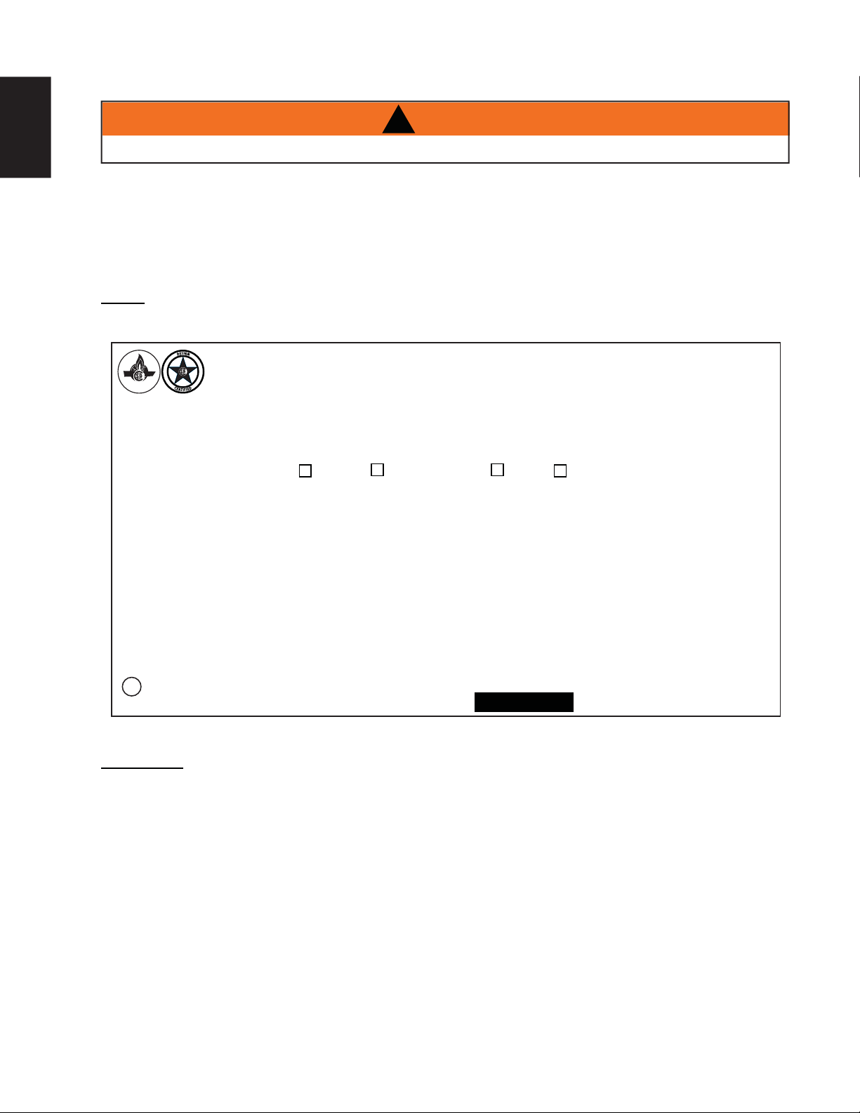
INSTALLER: It is your responsibility to check off the appropriate box on the rating plate according to
the model, venting and gas type of the appliance.
This illustration is for reference only. Refer to the rating plate on the appliance for accurate
information.
W415-1334 / 06.10.14
Page 9
2.5 SHIPPING HANDLES
IMPORTANT
This appliance fully dressed weighs 575lbs (261kg).
Shipping brackets were shipped secured to the appliance. The unit can be lifted by inserting the shipping
handle through a set of holes. Shipping brackets must eventually be removed if framing to minimum enclosure
dimensions.
When preparing to lift the appliance follow the directions and illustrations provided.
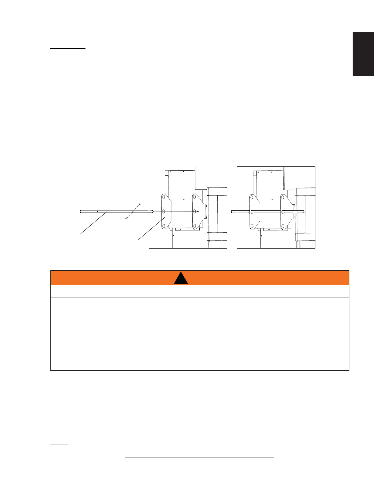
1. Locate the shipping handles provided with the bolts and wing nuts already attached.
2. Remove the bolt and wing nut from one end of the shipping handle and insert it into the appropriate set
of holes on the shipping bracket, most comfortable for lifting the appliance, as shown below.
3. Once the shipping handle is through the holes, reattach the bolt and wing nut to the handle, ensuring
they are secured on the outer sides of the shipping brackets, as shown below.
4. Repeat these steps to secure the second shipping handle on the opposite side of the appliance.
5. In all applications, the shipping handles must be removed once the appliance is located in it’s
fi nal position.
9
EN
SHIPPING
HANDLE
3.0 VENTING
RISK OF FIRE, MAINTAIN SPECIFIED AIR SPACE CLEARANCES TO VENT PIPE AND APPLIANCE.
IF VENTING IS INCLUDED WITH SPACERS THE VENT SYSTEM MUST BE SUPPORTED EVERY 3FT
(0.9m) FOR BOTH VERTICAL AND HORIZONTAL RUNS. USE SUPPORTS OR EQUIVALENT
NON-COMBUSTIBLE STRAPPING TO MAINTAIN THE REQUIRED CLEARANCE FROM
COMBUSTIBLES. USE WOLF STEEL LTD. SUPPORT RING ASSEMBLY W010-0370 OR EQUIVALENT
NON-COMBUSTIBLE STRAPPING TO MAINTAIN THE MINIMUM CLEARANCE TO COMBUSTIBLES
FOR BOTH VERTICAL AND HORIZONTAL RUNS. SPACERS ARE ATTACHED TO THE INNER PIPE AT
PREDETERMINED INTERVALS TO MAINTAIN AN EVEN AIR GAP TO THE OUTER PIPE. THIS GAP IS
REQUIRED FOR SAFE OPERATION. A SPACER IS REQUIRED AT THE START, MIDDLE AND END OF
EACH ELBOW TO ENSURE THIS GAP IS MAINTAINED. THESE SPACERS MUST NOT BE REMOVED.
This fi replaces uses 8” (203.2mm) exhaust / 10” (254mm) air intake vent pipe system.
For safe and proper operation of the fi replace follow the venting instruction exactly. Deviation from the minimum
vertical vent length can create diffi culty in burner start-up and/or carboning. Under extreme vent confi gurations,
allow several minutes (5-15) for the fl ame to stabilize after ignition. Provide a means for visually checking the vent
connection to the fi replace after the fi replace is installed. Use a fi restop, vent pipe shield or attic insulation shield
when penetrating interior walls, fl oor or ceiling.
SHIPPING
BRACKETS
!
WARNING
Refer to the section applicable to your installation.
NOTE: If for any reason the vent air intake system is disassembled; reinstall per the instructions provided
for the initial installation.
7.3B
W415-1334 / 06.10.14
Page 10

10
e
3.1 VENTING LENGTHS AND COMPONENTS FOR DIRECT VENT INSTALLATIONS
EN
For vent systems that provide seals on the inner exhaust fl ue, only the outer air intake joints must be sealed
using a red high temperature silicone (RTV). This same sealant may be used on both the inner exhaust and
outer intake vent pipe joints of all other approved vent systems except for the exhaust vent pipe connection to the
fi replace fl ue collar which must be sealed using the black high temperature sealant Mill Pac.
When using Wolf Steel venting components, use only approved Wolf Steel fl exible components with the
following termination kits: wall terminal kit GD622R, or 1/12 to 7/12 pitch roof terminal kit GD610, 8/12 to 12/12
roof terminal kit GD611 or fl at roof terminal kit GD612. With fl exible venting, in conjunction with the various
terminations, use either the 5 foot (1.5m) vent kit GD620 or the 10 foot (3m) vent kit GD630.
For optimum fl ame appearance and fi replace performance, keep the vent length and number of elbows to
a minimum.
The air terminal must remain unobstructed at all times. Examine the air terminal at least once a year to
verify that it is unobstructed and undamaged.
The minimum allowable vertical vent length is 3 feet (0.9m) maximum allowable vertical vent length is 40 feet
(12m). The maximum number of allowable 8” (203mm) vent connections is three horizontally or vertically
(excluding the fi replace and the air terminal connections).
When venting, the horizontal run must be kept to a minimum of 36” (914mm) or a maximum of 20 feet (6m).
If a 20 foot (6m) horizontal run is required, the fi replace must have a minimum vertical rise immediately off
the fi replace of 57” (1448mm). When terminating vertically, the vertical rise is a minimum 36” (914mm) and a
maximum 40 feet (12m) above the fi replace.
For optimum performance, it is recommended that all horizontal runs have a minimum 1/4” (6mm) rise
per foot/meter. Provide a means for visually checking the vent connection to the fi replace after the
fi replace is installed. Do not allow the inside liner to bunch up on horizontal or vertical runs and elbows.
Keep it pulled tight. A 3/4” (19mm) air gap between the inner and outer liner all around is required for saf
operation. Use a fi restop when penetrating interior walls, fl oor or ceiling.
8.4A
W415-1334 / 06.10.14
Page 11
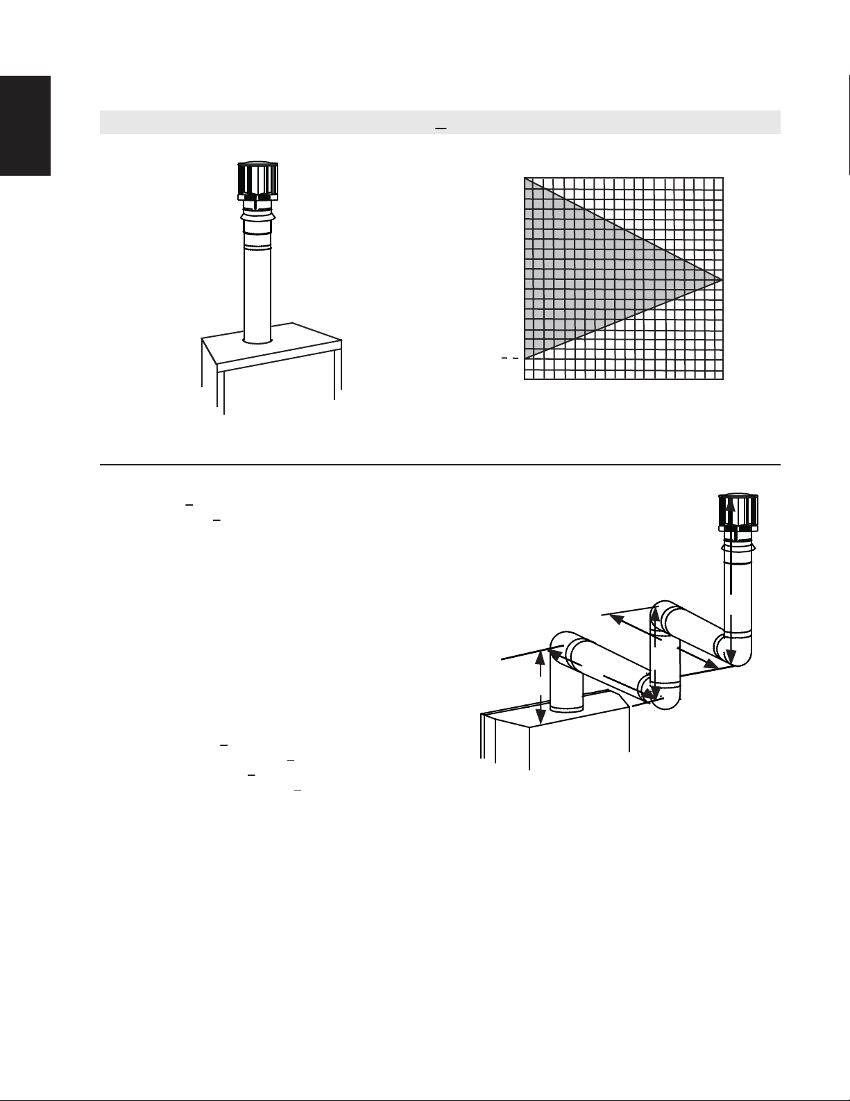
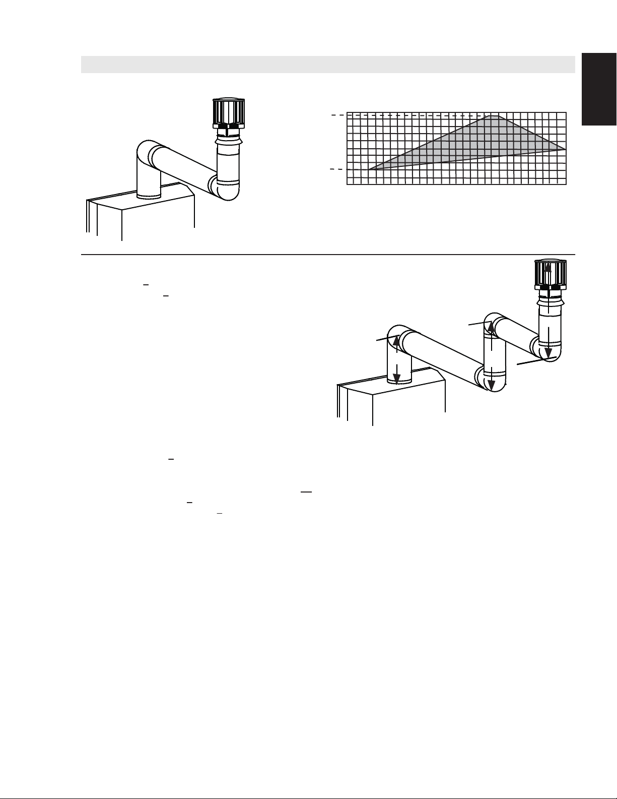
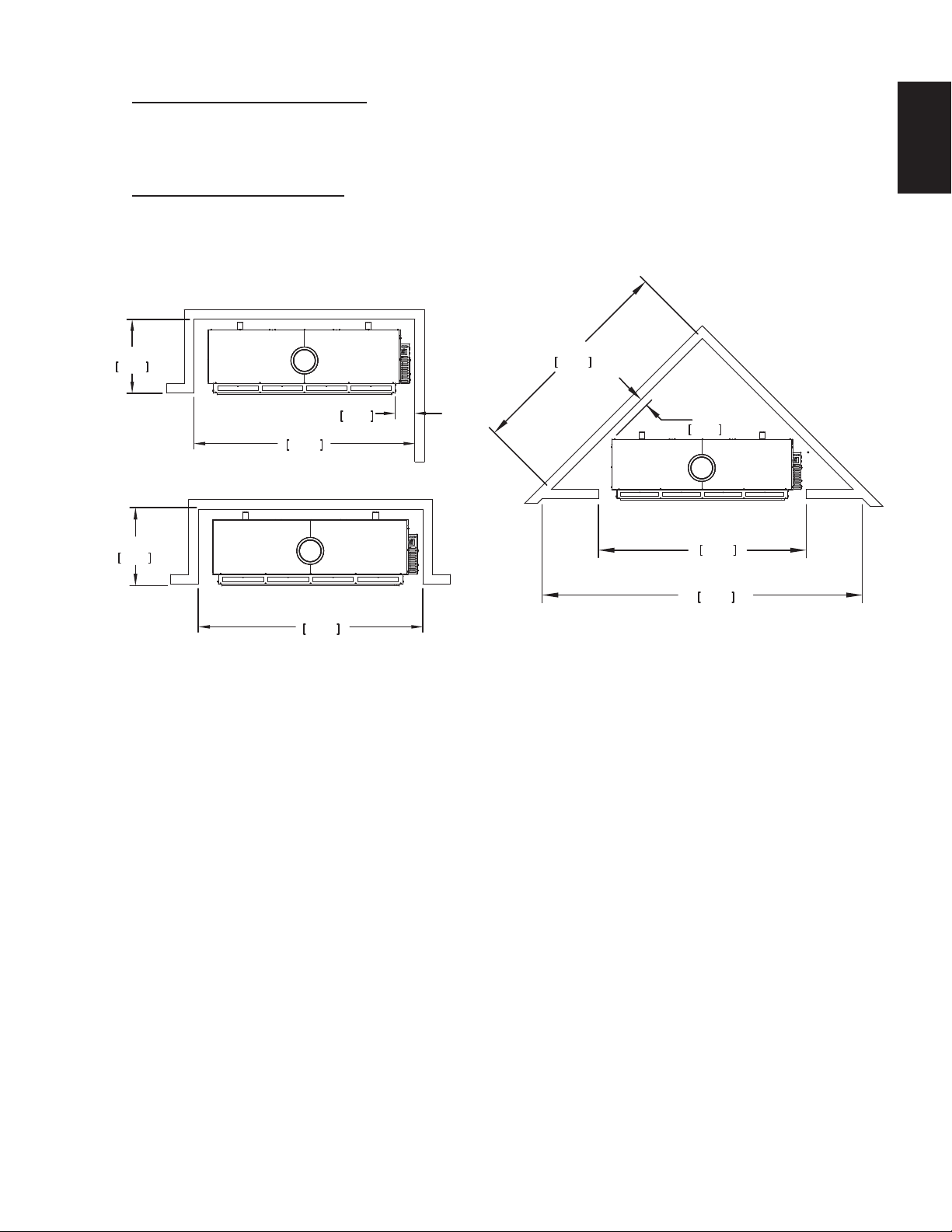
3.2 TYPICAL VENT INSTALLATIONS
11
EN
16” (406mm)
MINIMUM
20” (508mm)
MAXIMUM
48” (1219mm)
MINIMUM
36”
(914mm)
* See “VENTING” section.
40 FEET (12m)
MAXIMUM
3 FEET (1m)
MINIMUM
84” (2134mm)
MINIMUM
PLUS
RISE*
36”
(914mm)
W415-1334 / 06.10.14
Page 12
12
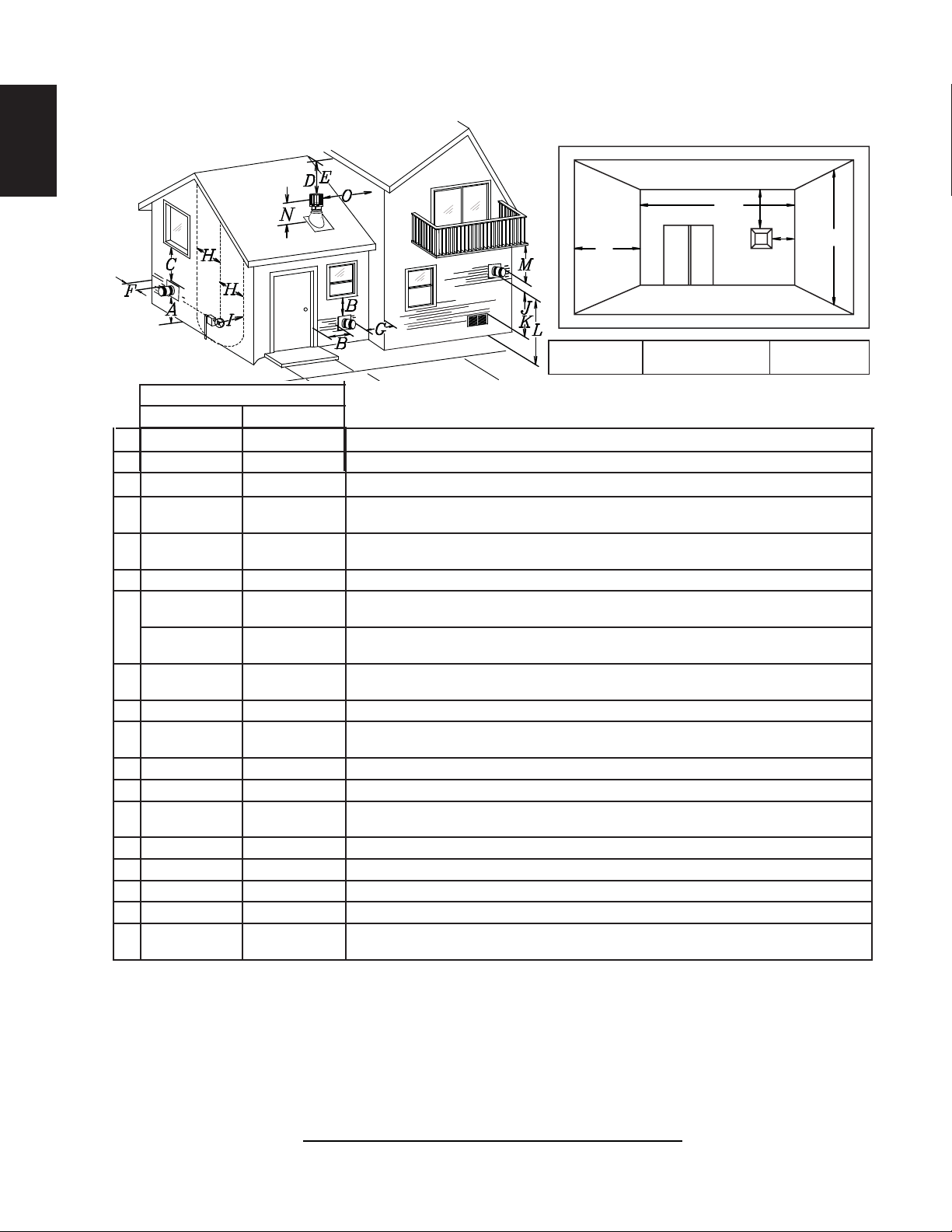
3.3 MINIMUM AIR TERMINAL LOCATION CLEARANCES
EN
COVERED BALCONY APPLICATIONS
Q
M
R
Q
= 3 feet
MIN
(0.9m)
INSTALLATIONS
CANADA U.S.A.
A 12” (304.8mm) 12” (304.8mm) Clearance above grade, veranda porch, deck or balcony.
B 12” (304.8mm)
Δ
9” (228.6mm) ΔClearance to windows or doors that open.
C 12” (304.8mm)* 12” (304.8mm)* Clearance to permanently closed windows.
D
E
18”
(457.2mm)**
12”
(304.8mm)**
18” (457.2mm)**
12” (304.8mm)** Clearance to unventilated soffi t.
Vertical clearance to ventilated soffi ts located above the terminal within a horizontal distance
of 2’ (0.6m) from the centerline of the terminal.
F 0” (0mm) 0” (0mm) Clearance to an outside corner wall.
0” (0mm)*** 0” (0mm)***
G
2” (50.8mm)*** 2” (50.8mm)***
H 3’ (0.9m) 3’ (0.9m)****
Clearance to an inside non-combustible corner wall or protruding non-combustible obstructions (chimney, etc.).
Clearance to an inside combustible corner wall or protruding combustible obstructions (vent
chase, etc.).
Clearance to each side of the centerline extended above the meter / regulator assembly to a
maximum vertical distance of 15’ (4.6m).
I 3’ (0.9m) 3’ (0.9m)**** Clearance to a service regulator vent outlet.
J 12” (304.8mm) 9” (228.6mm)
Clearance to a non-mechanical air supply inlet to the building or a combustion air inlet to any other
appliance.
K 6’ (1.8m) 3’ (0.9m) Clearance to a mechanical air supply inlet.
L 7’ (2.1m)‡ 7’ (2.1m)**** Clearance above a paved sidewalk or paved driveway located on public property.
M
12”
(304.8mm)††
12”
(304.8mm)****
Clearance under a veranda, porch, deck or balcony.
N 16” (406.4mm) 16” (406.4mm) Clearance above the roof.
O 2’ (0.61m)†* 2’ (0.61m)†* Clearance from an adjacent wall including neighbouring buildings.
P 8’ (2.4m) 8’ (2.4m) Roof must be non-combustible without openings.
Q 3’ (0.9m) 3’ (0.9m) See chart for wider wall dimensions.
R 6’ (1.8m) 6’ (1.8m)
The terminal shall not be located less than 6 feet (1.8m) under a window that opens on a horizontal plane in a structure with three walls and a roof.
Δ
* Recommended to prevent condensation on windows and thermal breakage
** It is recommended to maximize the distance to vinyl clad soffi ts.
*** The periscope requires a minimum 18” (457.2mm) clearance from an inside corner.
**** This is a recommended distance. For additional requirements check local codes.
† 3 feet (0.91m) above if within 10 feet (3.1m) horizontally.
‡ A vent shall not terminate where it may cause hazardous frost or ice accumulations on adjacent property surfaces.
†† Permitted only if the veranda, porch, or deck is fully open on a minimum of two sides beneath the fl oor.
†* Recommended to prevent recirculation of exhaust products. For additional requirements check local codes.
See chart for deeper wall dimensions. The terminal shall not be installed on any wall that has
an opening between the terminal and the open side of the structure.
R
= 2 x
MAX
Q
ACTUAL
12.3C
R
G
MAX
P
IHHW
(4.6m)
W415-1334 / 06.10.14
Page 13
3.4 VENT APPLICATION FLOW CHART
13
Horizontal Termination
Vertical rise is equal
to or greater than
the horizontal run
Horizontal run +
vertical rise to
maximum of 40 feet
(12m)
3.5 DEFINITIONS
For the following symbols used in the venting calculations and examples are:
> - greater than
> - equal to or greater than
< - less than
< - equal to or less than
HT - total of both horizontal vent lengths (Hr) and offsets (Ho) in feet
HR - combined horizontal vent lengths in feet
HO - offset factor: .03 (total degrees of offset - 90°*) in feet
VT - combined vertical vent lengths in feet
TOP EXIT
Vertical rise is less
than horizontal run
Horizontal run +
vertical rise to
maximum of
24.75 feet (7.5m)
4.2 times the
vertical rise equal to
or greater than the
horizontal run
Vertical Termination
Vertical rise is equal
to or greater than
the horizontal run
Horizontal run +
vertical rise to
maximum of 40 feet
(12m)
EN
Vertical rise is less
than horizontal run
Horizontal run +
vertical rise to
maximum of 40 feet
(12m)
3 times the vertical
rise equal to or
greater than the
horizontal run
13.1A
14.1
3.6 ELBOW VENT LENGTH VALUES
FEET INCHES MILLIMETERS
1° 0.03 0.5 12.7
15° 0.45 6.0 152.4
30° 0.9 11.0 279.4
45° 1.35 16.0 406.4
90°* 2.7 32.0 812.8
* The fi rst 90° offset has a zero value and is shown in the formula as - 90°
15.1A
W415-1334 / 06.10.14
Page 14
14
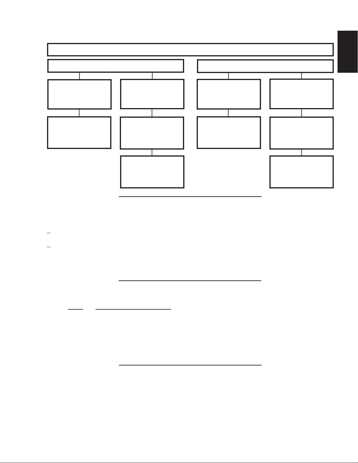
3.7 HORIZONTAL TERMINATION
EN
(HT) < (VT)
Simple venting confi guration (only one 90° elbow)
See graph to determine the required vertical
rise VT for the required horizontal run HT.
40 (12.2)
39 (11.9)
REQUIRED
30 (9.1)
VERTICAL
RISE IN FEET
20 (6.1)
(MEETERS) VT
10 (3.1)
4 (1.2)
0
2.5
(0.8)5 (1.5)
7.5
(2.3)
(3.1)
10
12.5
(3.8)
HORIZONTAL VENT RUN PLUS OFFSET IN
FEET (METERS) H
The shaded area within the lines represents
acceptable values for HT and V
Min. V
= 48"; H
T
HT = V
T
should start at 48"
T
For vent confi gurations requiring more than one 90° elbow, the following formulas apply:
Formula 1: HT < V
T
Formula 2: HT + VT < 40 feet (12.2m)
T
15
(4.6)
17.5
(5.3)
20
(6.1)
T
Example:
V1 = 3 FT (0.9m)
V2 = 8 FT (2.4m)
VT = V1 + V2= 3 FT (0.9m) + 8 FT (2.4m) = 11 FT (3.4m)
H1 = 2.5 FT (0.8m)
H2 = 2 FT (0.6m)
HR = H1 + H2 = 2.5 FT (0.8m) + 2 FT (0.6m) = 4.5 FT (1.4m)
HO = .03 (three 90° elbows - 90°) = .03 (270° - 90°) = 5.4 FT (1.6m)
HT = HR + HO = 4.5 FT (1.4m) + 5.4 FT (1.6m) = 9.9 FT (3m)
HT + VT = 9.9 FT (3m) + 11 FT (3.4m) = 20.9 FT (6.4m)
Formula 1: HT < V
T
9.9 FT (3m) < 11 FT (3.4m)
Formula 2: HT + VT < 40 FT (12.2m)
20.9 FT (6.4m) < 40 FT (12.2m)
Since both formulas are met, this vent confi guration is acceptable.
90°
90°
V
2
H
2
90°
H
1
V
1
W415-1334 / 06.10.14
Page 15
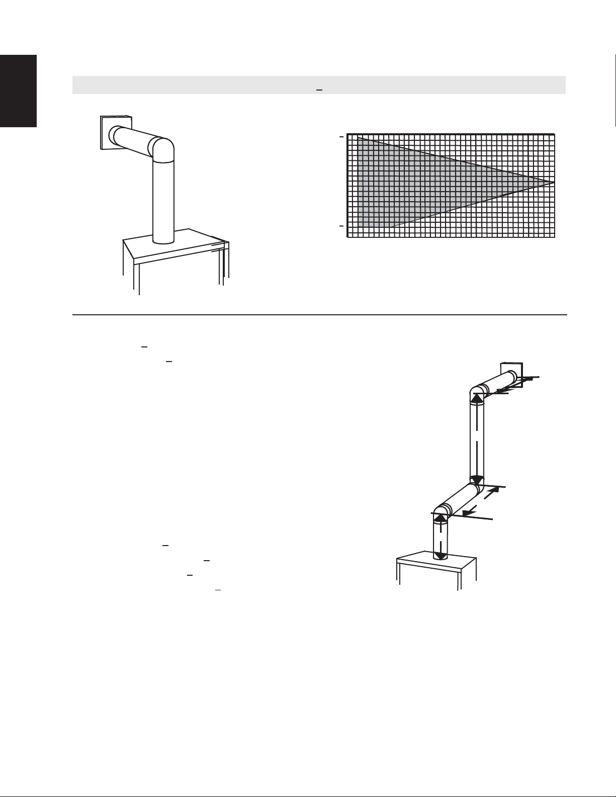
15
V
V
V
V
(HT) > (VT)
Simple venting configuration (only one 90° elbow)
See graph to determine the required vertical rise VT for the
150 (45.7)
147” (44.8)
required horizontal run H
.
T
EN
REQUIRED
VERTICAL
100 (30.5)
RISE IN
INCHES
(METERS)V
HORIZONTAL VENT RUN PLUS OFFSET IN FEET (METERS)H
The shaded area within the lines represents acceptable
T
57” (17.4)
48” (14.6)
50 (15.2)
40 (12.2)
0
(1.5)
2
(0.6)
10
5
(3.1)
12.5
(3.8)
15
(4.6)
19.5
(5.9)
20 (6.1)
T
values for HT and VT
For vent configurations requiring more than one 90° elbow, the following formulas apply:
H
Formula 1:
Formula 2: HT + V
< 4.2 V
T
T
< 24.75 feet (7.5m)
T
90°
H
1
H
2
Example:
= VT = 6 FT (1.8m)
1
H
= 3 FT (0.9m)
1
H
= 5 FT (1.5m)
2
H
= H
+ H
R
H
= .03 (two 90° elbows - 90°) = .03 (180° - 90°) = 2.7FT (0.8m)
O
H
= H
T
H
+ V
T
= 3FT (0.9m) + 5FT (1.5m) = 8FT (2.4m)
1
2
+ H
= 8FT (2.4m) + 2.7FT (0.8m) = 10.7FT (3.3m)
R
O
= 10.7FT (3.3m) + 6FT (1.8m) = 16.7FT (5.1m)
T
V
1
90°
Formula 1: HT < 4.2 V
4.2 VT = 4.2FT (1.3m) x 6FT (1.8m) = 25.2FT (7.7m)
10.7FT (3.3m) < 25.2FT (7.7m)
Formula 2: HT + V
16.7 (5.1m) < 24.75 (7.5m)
Since both formulas are met, this vent configuration is acceptable.
Example:
= 4 FT (1.2m)
1
= 1.5 FT (0.5m)
2
= V
+ V
T
H
= 2 FT (0.6m)
1
H
= 1 FT (0.3m)
2
H
= 1 FT (0.3m)
3
H
= 1.5 FT (0.5m)
4
H
= H
R
H
= .03 (four 90° elbows - 90°) = .03 (360° - 90°) = 8.1 FT (2.5m)
O
H
= H
T
H
+ V
T
= 4FT (1.2m) + 1.5FT (0.5m) = 5.5FT (1.7m)
1
2
+ H2 + H
1
+ H
R
= 13.6FT (4.2m) + 5.5FT (1.7m) = 19.1 FT (5.8m)
T
+ H4 = 2FT (0.6m) + 1FT (0.3m) + 1FT (0.3m) + 1.5FT (0.5m) = 5.5FT (1.7m)
3
= 5.5 FT (1.7m) + 8.1 FT (2.5m) = 13.6 FT (4.2m)
O
Formula 1: HT < 4.2 V
4.2 VT = 4.2FT (1.3m) x 5.5FT (1.7m) = 23.1FT (7m)
T
< 24.75 FT (7.5m)
T
T
90°
90°
90°
H
1
90°
V
1
V
2
H
H
2
3
H
4
13.6 FT (4.2m) < 23.1 FT (7m)
Formula 2: HT + V
19.1 FT (5.8m) < 24.75 FT (7.5m)
< 24.75 FT (7.5m)
T
Since both formulas are met, this vent configuration is acceptable.
W415-1334 / 06.10.14
Page 16
16
3.8 VERTICAL TERMINATION
EN
(HT) < (VT)
Simple venting configurations.
See graph to determine the required vertical rise V
required horizontal run H
40 (12.2)
30 (9.1)
REQUIRED
VERTICAL
RISE IN
FEET
(METERS) V
T
4 (1.2)
20 (6.1)
10 (3.1)
0
5
(1.5)
HORIZONTAL VENT RUN PLUS OFFSET IN FEET (METERS)H
The shaded area within the lines represents acceptable
values for H
For vent configurations requiring one or more 90° elbows the following formulas apply:
Formula 1: H
Formula 2: HT + V
< V
T
T
< 40 feet (12.2m)
T
10
(3.1)
and VT
T
15
(4.6)
for the
20
(6.1)
T
T
.
T
Example:
V
= 5 FT (1.5m)
1
V
= 6 FT (1.8m)
2
V
= 10 FT (3.1m)
3
V
= V
+ V2 + V3 = 5FT (1.5m) + 6FT (1.8m) + 10FT (3.1m) = 21FT (6.4m)
T
1
H
= 8 FT (2.4m)
1
H
= 2.5 FT (0.8m)
2
H
= H
+ H
R
H
= .03 (four 90° elbows - 90°)
O
= .03 (360° - 90°) = 8.1 FT (2.5m)
H
= H
T
H
+ V
T
Formula 1: HT < V
18.6FT (5.7m) < 21FT (6.4m)
Formula 2: HT + V
39.6FT (12.1m) < 40FT (12.2m)
= 8FT (2.4m) + 2.5FT (0.8m) = 10.5 FT (3.2m)
1
2
+ H
= 10.5FT (3.2m) + 8.1FT (2.5m) = 18.6FT (5.7m)
R
O
= 18.6FT (5.7m) + 21FT (6.4m) = 39.6FT (12.1m)
T
T
< 40 FT (12.2m)
T
Since both formulas are met, this vent configuration is acceptable.
V
90°
1
90°
V
3
H
2
V
H
1
2
90°
90°
W415-1334 / 06.10.14
Page 17
17
(HT) > (VT)
Simple venting configurations.
See graph to determine the required vertical rise V
required horizontal run H
20 (6.1)
19 (5.8)
REQUIRED
4 (1.2)
T
10 (3.1)
0
5
(1.5)
10
(3.1)
15
(4.6)
VERTICAL
RISE IN
FEET
(METERS)V
HORIZONTAL VENT RUN PLUS OFFSET IN FEET
(METERS)H
The shaded area within the lines represents acceptable
values for H
For vent configurations requiring more than two 90° elbows the following formulas apply:
Formula 1: H
Formula 2: HT + V
< 3V
T
T
< 40 feet (12.2m)
T
Example:
V
= 2 FT (0.6m)
1
V
= 1 FT (0.3m)
2
V
= 1.5 FT (0.5m)
3
V
= V
+ V2 + V3 = 2FT (0.6m) + 1FT (0.3m) + 1.5FT (0.5m) = 4.5FT (1.4m)
T
1
H
= 6 FT (1.8m)
1
H
= 2 FT (0.6m)
2
H
= H
+ H
R
H
= .03 (four 90° elbows - 90°)
O
= .03 (360° - 90°) = 8.1 FT (2.5m)
H
= H
T
H
+ V
T
= 6FT (1.8m) + 2FT (0.6m) = 8 FT (2.4m)
1
2
+ H
= 8FT (2.4m) + 8.1FT (2.5m) = 16.1FT (4.9m)
R
O
= 16.1FT (4.9m) + 4.5FT (1.4m) = 20.6FT (6.3m)
T
90°
H
V
1
1
(6.1)
T
and VT
T
90°
20
V
for the
2
25
(7.6)
T
V
3
.
T
H
2
EN
30
(9.1)
90°
90°
Formula 1: HT < 3V
3VT = 3FT (0.9m) x 4.5FT (1.4m) = 13.5FT (4.1m)
T
16.1FT (4.9m) > 13.5FT (4.1m)
Since this formula is not met, this vent configuration is unacceptable.
Formula 2: HT + VT < 40 feet (12.2m)
20.6FT (6.3m) < 40 (12.2m)
Since only formula 2 is met, this vent configuration is unacceptable and a new appliance location or vent configuration will
need to be established to satisfy both formulas.
W415-1334 / 06.10.14
Page 18
18
4.0 INSTALLATION
EN
ENSURE TO UNPACK ALL LOOSE MATERIALS FROM INSIDE THE FIREBOX PRIOR TO HOOKING UP
THE GAS AND ELECTRICAL SUPPLY.
IF YOUR APPLIANCE IS SUPPLIED WITH A REMOTE ENSURE THE REMOTE RECEIVER IS IN THE
“OFF” POSITION PRIOR TO HOOKING UP THE GAS AND ELECTRICAL SUPPLY TO THE APPLIANCE.
FOR SAFE AND PROPER OPERATION OF THE APPLIANCE, FOLLOW THE VENTING INSTRUCTIONS
ALL INNER EXHAUST AND OUTER INTAKE VENT PIPE JOINTS MAY BE SEALED USING EITHER RED
RTV HIGH TEMP SILICONE SEALANT W573-0002 (NOT SUPPLIED) OR BLACK HIGH TEMP MILL PAC
W573-0007 (NOT SUPPLIED) WITH THE EXCEPTION OF THE APPLIANCE EXHAUST FLUE COLLAR
WHICH MUST BE SEALED USING MILL PAC.
IF USING PIPE CLAMPS TO CONNECT VENT COMPONENTS, 3 SCREWS MUST ALSO BE USED TO
ENSURE THE CONNECTION CANNOT SLIP OFF.
DO NOT CLAMP THE FLEXIBLE VENT PIPE.
RISK OF FIRE, EXPLOSION OR ASPHYXIATION. IMPROPER SUPPORT OF THE ENTIRE VENTING
SYSTEM MAY ALLOW VENT TO SAG AND SEPARATE. USE VENT RUN SUPPORTS AND CONNECT
VENT SECTIONS PER INSTALLATION INSTRUCTIONS.
RISK OF FIRE, DO NOT ALLOW LOOSE MATERIALS OR INSULATION TO TOUCH THE VENT PIPE.
REMOVE INSULATION TO ALLOW FOR THE INSTALLATION OF THE ATTIC SHIELD AND TO
MAINTAIN CLEARANCES TO COMBUSTIBLES.
4.1 WALL AND CEILING PROTECTION
!
WARNING
EXACTLY.
68.2B
!
WARNING
DO NOT FILL THE SPACE BETWEEN THE VENT PIPE AND ENCLOSURE WITH ANY TYPE OF
MATERIAL. DO NOT PACK INSULATION OR COMBUSTIBLES BETWEEN CEILING FIRESTOPS.
ALWAYS MAINTAIN SPECIFIED CLEARANCES AROUND VENTING AND FIRESTOP SYSTEMS.
INSTALL WALL SHIELDS AND FIRESTOPS AS SPECIFIED. FAILURE TO KEEP INSULATION OR
OTHER MATERIALS AWAY FROM VENT PIPE MAY CAUSE FIRE.
70.1
For optimum performance it is recommended that all horizontal runs have a minimum of 1/4” (6.4mm) rise
per foot (0.3m) using fl exible venting. For safe and proper operation of the appliance, follow the venting
instructions exactly.
W415-1334 / 06.10.14
Page 19
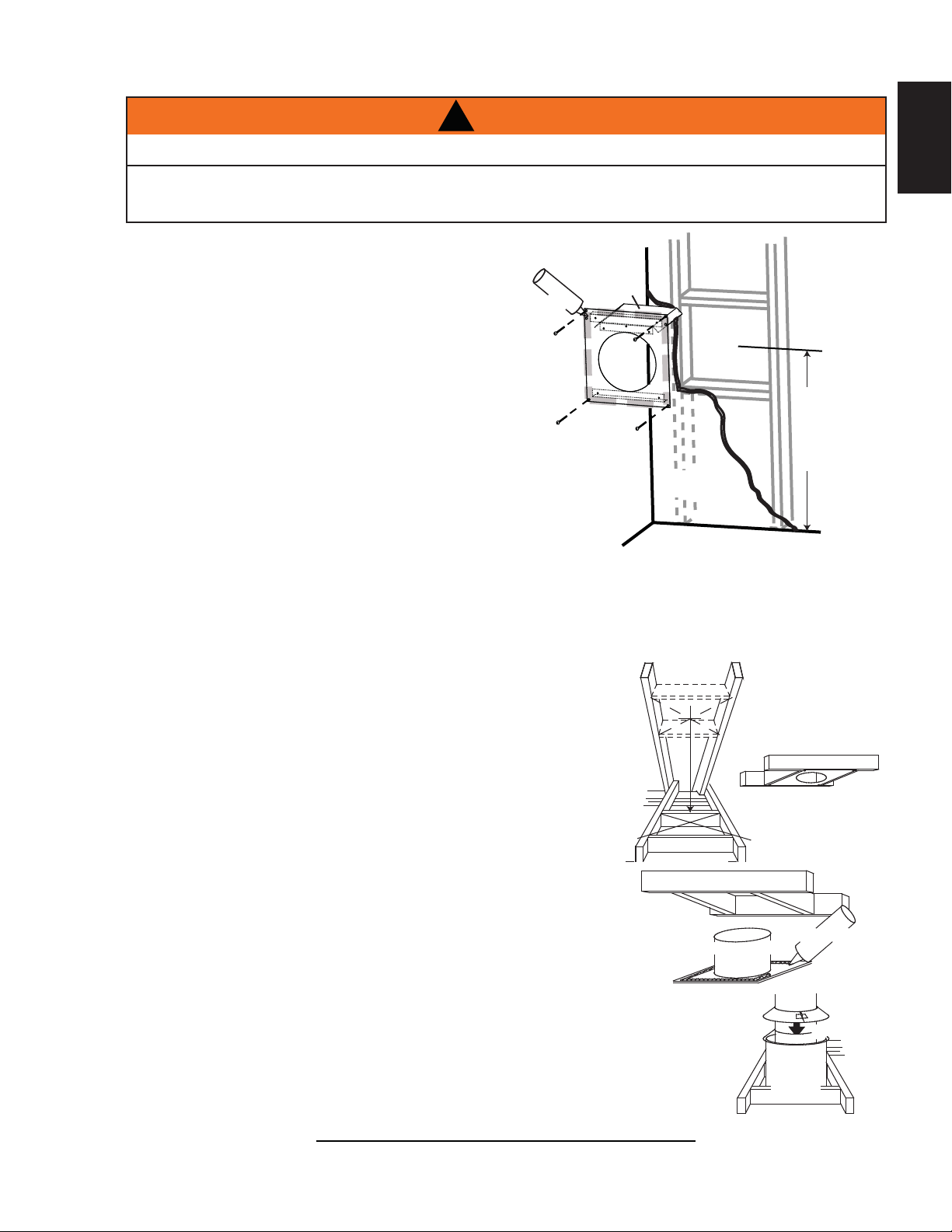
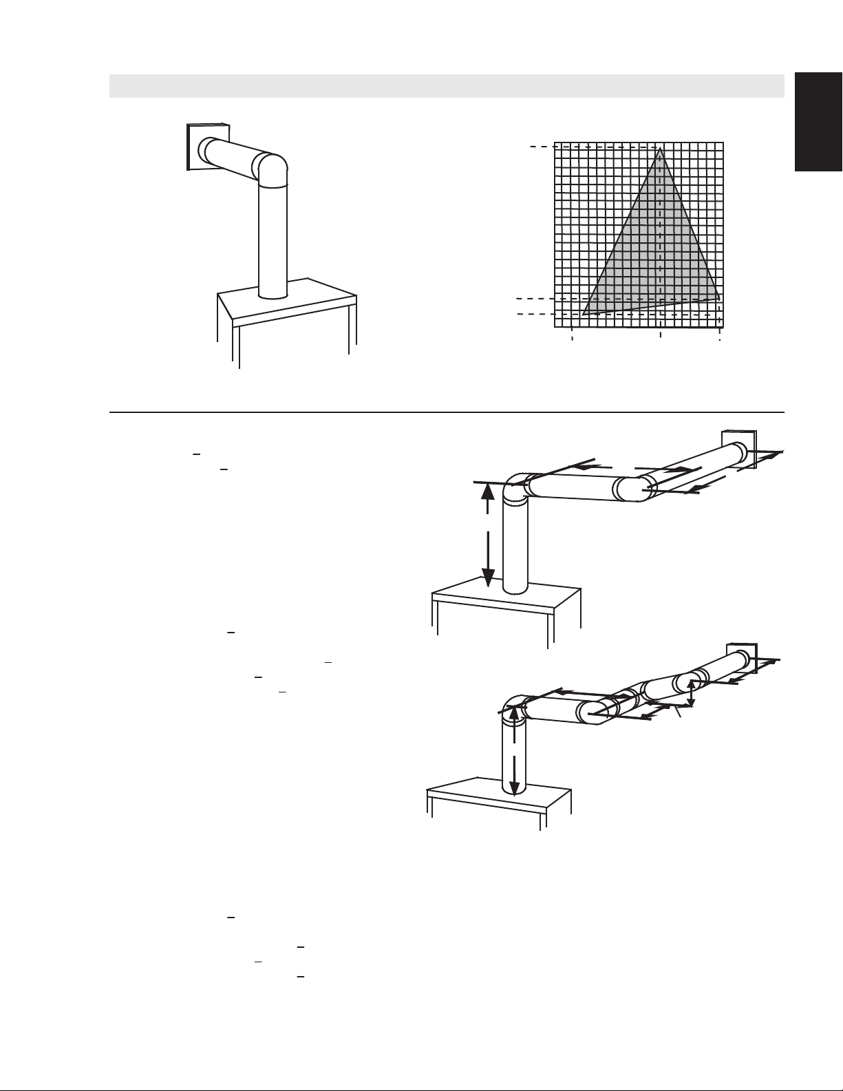
4.1.1 HORIZONTAL INSTALLATION
THE FIRESTOP ASSEMBLY MUST BE INSTALLED WITH THE VENT SHIELD TO THE TOP.
TERMINALS MUST NOT BE RECESSED INTO A WALL OR SIDING MORE THAN THE DEPTH OF THE
RETURN FLANGE OF THE MOUNTING PLATE.
This application occurs when venting through an exterior wall.
Having determined the correct height for the air terminal
location, cut and frame a hole in the exterior wall as
illustrated to accommodate the fi restop assembly.
Dry fi t the fi restop assembly before proceeding to
ensure the brackets on the rear surface fi t to the
inside surface of the horizontal framing.
The vent shield is telescopic and must be adjusted
to shield the full depth of the combustible wall
penetration. The length of the vent shield may be cut
shorter for combustible walls that are less than 6" (152mm)
thick.
A. Apply a bead of caulking (not supplied) around the corner edge of
the inside surface of the fi restop assembly, fi t the fi restop
assembly to the hole and secure using the 4 screws (supplied in
your manual baggie).
!
WARNING
CAULKING
FIRESTOP
SPACER
19
EN
VENT
SHIELD
DETERMINE
THE
CORRECT
HEIGHT
FINISHING
MATERIAL
B. Once the vent pipe is installed in its fi nal position, apply high temperature sealant W573-0007 (not
supplied) between the pipe and the fi restop.
4.1.2 VERTICAL INSTALLATION
This application occurs when venting through a roof. Installation kits for
various roof pitches are available from your authorized dealer / distributor. See
accessories to order specifi c kits required.
A. Determine the air terminal location, cut and frame a square opening as
illustrated in the ceiling and the roof to provide the minimum 1“ (25mm)
clearance between the vent pipe and any combustible material. Try to center
the vent pipe location midway between two joists to prevent having to cut
them. Use a plumb bob to line up the center of the openings. A vent pipe
shield will prevent any materials such as insulation, from fi lling up the 1”
(25mm) air space around the pipe. Nail headers between the joist for
extra support.
B. Apply a bead of caulking (not supplied) to the framework or to the Wolf
Steel vent pipe shield plate or equivalent (in the case of a fi nished ceiling),
and secure over the opening in the ceiling. A fi restop must be placed on the
bottom of each framed opening in a roof or ceiling that the venting system passes
through. Apply a bead of caulking all around and place a fi restop spacer over
the vent shield to restrict cold air from being drawn into the room or around the
fi replace. Ensure that both spacer and shield maintain the required clearance to
combustibles. Once the vent pipe is installed in its fi nal position, apply sealant between the
pipe and the fi restop assembly.
C. In the attic, slide the vent pipe collar down to cover up the open end of the shield and
tighten. This will prevent any materials, such as insulation, from fi lling up the 1” (25mm) air
space around the pipe.
FIRESTOP
UNDERSIDE OF
JOIST
VENT PIPE
SHIELD
SHIELD
21.1
CAULKING
VENT
PIPE
COLLAR
VENT
PIPE
W415-1334 / 06.10.14
Page 20
20
4.2 USING FLEXIBLE VENT COMPONENTS
EN
DO NOT ALLOW THE INNER FLEX PIPE TO BUNCH UP ON HORIZONTAL OR VERTICAL RUNS AND ELBOWS.
KEEP IT PULLED TIGHT.
SPACERS ARE ATTACHED TO THE INNER FLEX PIPE AT PREDETERMINED INTERVALS TO MAINTAIN AN EVEN
AIR GAP TO THE OUTER FLEX PIPE. THIS GAP IS REQUIRED FOR SAFE OPERATION. A SPACER IS REQUIRED
AT THE START, MIDDLE AND END OF EACH ELBOW TO ENSURE THIS GAP IS MAINTAINED. THESE SPACERS
MUST NOT BE REMOVED.
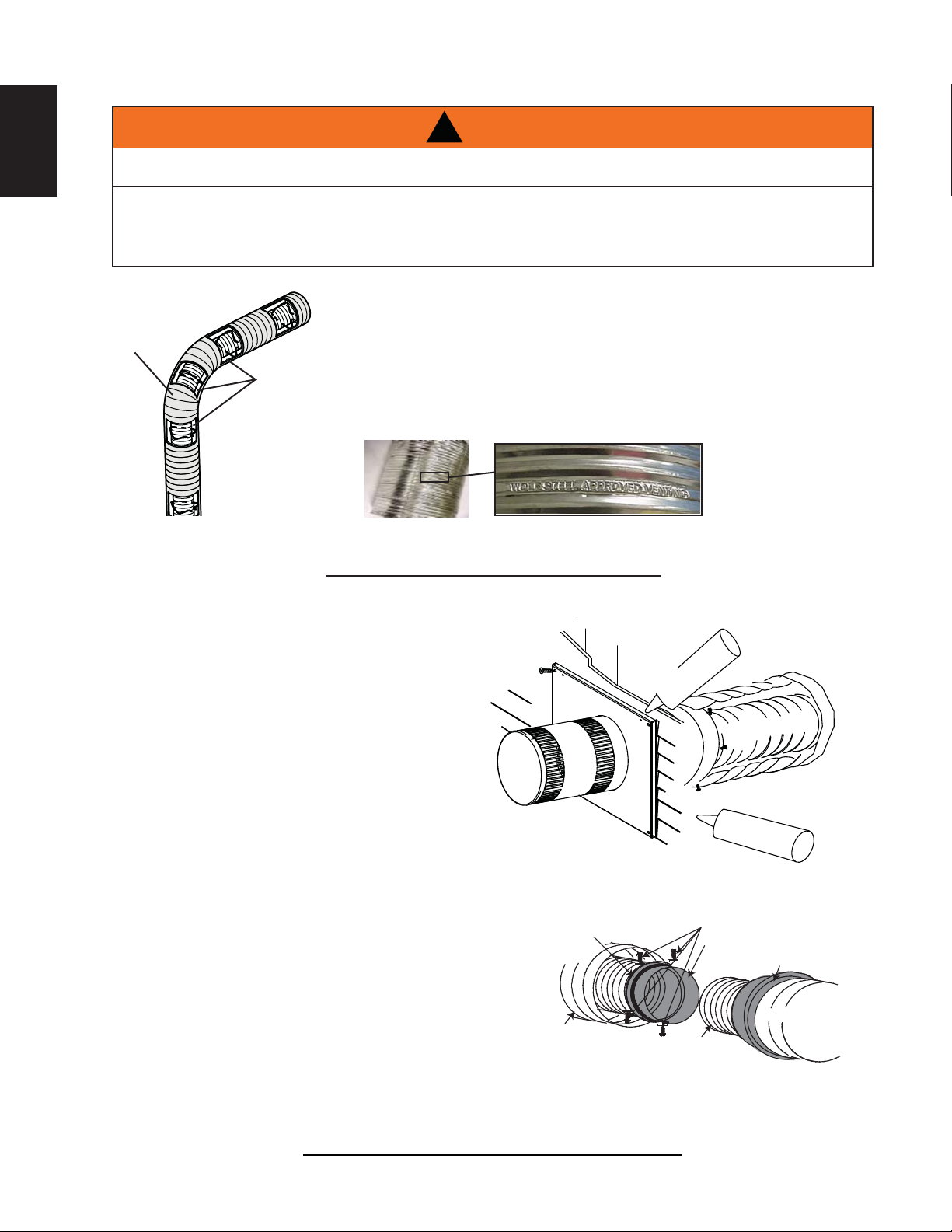
For safe and proper operation of the appliance, follow the venting
instructions exactly.
All inner fl ex pipe and outer fl ex pipe joints may be sealed using high
ELBOW
SPACERS
temperature sealant W573-0002 (not supplied) or the high temperature
sealant W573-0007 Mill Pac (not supplied). However, the high temperature
sealant W573-0007 Mill Pac (not supplied) must be used on the joint
connecting the inner fl ex pipe and the exhaust fl ue collar.
Use only approved fl exible vent pipe kits marked:
!
WARNING
“Wolf Steel Approved Venting” as identifi ed
by the stamp only on the outer fl ex pipe.
4.2.1 HORIZONTAL AIR TERMINAL INSTALLATION
A. Stretch the inner fl ex pipe to the required
length needed for the fi nished wall surface.
Apply a heavy bead of high temperature
sealant W573-0007 Mill Pac (not supplied) to
the inner sleeve of the air terminal. Slip the
vent pipe a minimum of 2” (50.8mm) over the
inner sleeve of the air terminal and secure
with 3 #8 screws.
B. Using the outer fl ex pipe, slide over the outer
combustion air sleeve of the air terminal
and secure with 3 #8 screws. Seal using
high temperature sealant W573-0002 (not
supplied).
C. Insert the vent pipes through the fi restop
maintaining the required clearance to
combustibles. Holding the air terminal (lettering
in an upright, readable position), secure to the
exterior wall and make weather tight by sealing
with caulking (not supplied).
#10x2"
SCREWS
HI-TEMP
SEALANT
22.1
OUTER FLEX
PIPE
CAULKING
INNER FLEX
PIPE
2" (50.8mm) OVERLAP
HI-TEMP
SEALANT
#8 X 1/2” SELF DRILLING
SCREWS & WASHERS
INNER COUPLER
OUTER COUPLER
D. If more vent pipe needs to be used to
reach the fi replace, couple them together
as illustrated. The vent system must be
supported approximately every 3 feet (0.9mm)
for both vertical and horizontal runs. Use
noncombustible strapping to maintain the
minimum 1” (25.4mm) clearance to combustibles.
The air terminal mounting plate may be recessed into the exterior wall or siding no greater than the depth
of its return fl ange.
W415-1334 / 06.10.14
OUTER
FLEX PIPE
INNER
FLEX PIPE
23.3B
OUTER
FLEX PIPE
Page 21
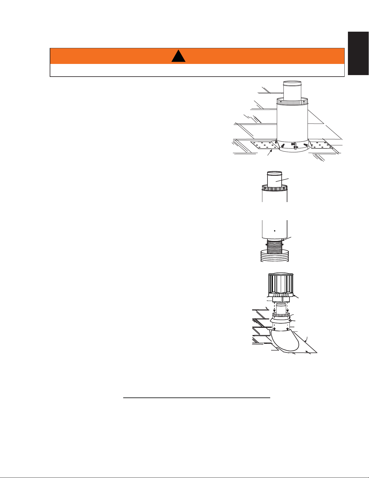
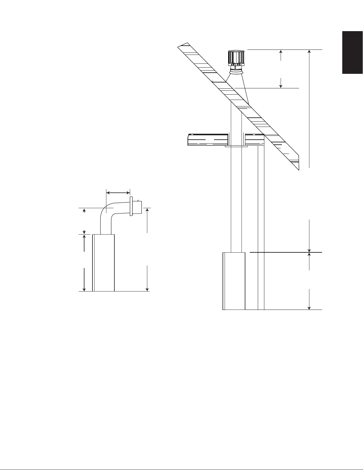
4.2.2 VERTICAL AIR TERMINAL INSTALLATION
21
!
WARNING
MAINTAIN A MINIMUM 2” (51mm) SPACE BETWEEN THE AIR INLET BASE AND THE STORM COLLAR.
A. Fasten the roof support to the roof using the screws provided. The
roof support is optional. In this case the venting is to be adequately
supported using either an alternate method suitable to the
authority having jurisdiction or the optional roof support.
B. Stretch the inner fl ex pipe to the required length. Slip the
inner fl ex pipe a minimum of 2” (51mm) over the inner pipe
of the air terminal connector and secure with 6 #8 screws.
Seal using a heavy bead of high temperature sealant
W573-0007 (not supplied).
C. Repeat using the outer fl ex pipe, using a heavy bead of
high temperature sealant W573-0002 (not supplied).
D. Thread the air terminal connector / vent pipe assembly down
through the roof. The air terminal must be positioned vertically
and plumb. Attach the air terminal connector to the roof support,
ensuring that the top of the air terminal is 16” (406mm) above the
highest point that it penetrates the roof.
E. Remove nails from the shingles, above and to the sides of the
air terminal connector. Place the fl ashing over the air terminal
connector leaving a min. 3/4” (19mm) of the air terminal connector
showing above the top of the fl ashing. Slide the fl ashing
underneath the sides and upper edge of the shingles. Ensure that
the air terminal connector is properly centred within the fl ashing,
giving a 3/4” (19mm) margin all around. Fasten to the roof.
Do not nail through the lower portion of the fl ashing. Make
weather-tight by sealing with caulking. Where possible, cover
the sides and top edges of the fl ashing with roofi ng material.
2” (51mm)
F. Aligning the seams of the terminal and air terminal connector,
place the terminal over the air terminal connector making
sure the vent pipe goes into the hole in the terminal. Secure
with the three screws provided.
G. Apply a heavy bead of weatherproof caulking 2” (51mm)
above the fl ashing. Install the storm collar around the air
terminal and slide down to the caulking. Tighten to ensure
that a weather-tight seal between the air terminal and the
collar is achieved.
ROOF SUPPORT
INNER PIPE
AIR
TERMINAL
CONNECTOR
HIGH
TEMPERATURE
SEALANT
INNER FLEX PIPE
OUTER FLEX PIPE
AIR I NL ET
BASE
CAULKING
STORM COLLAR
WEA THER
SEALANT
FLASHING
EN
H. If more vent pipe needs to be used to reach the fi replace see “HORIZONTAL AIR TERMINAL
INSTALLATION” section.
24.2A
W415-1334 / 06.10.14
Page 22
22
A
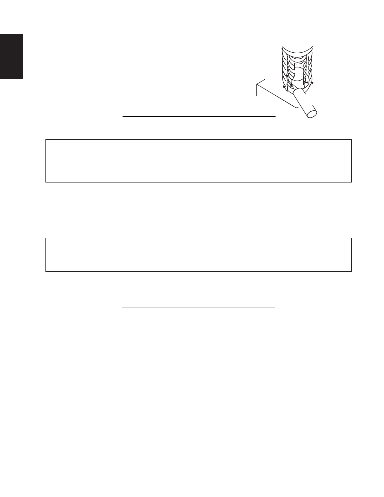
4.2.3 APPLIANCE VENT CONNECTION
A. Install the inner fl ex pipe to the appliance. Secure with 6 screws
EN
B. Install the outer fl ex pipe to the appliance. Secure with 6 screws
W573-0002 (not supplied).
4.3 MOBILE HOME INSTALLATION
This appliance is also certifi ed to be installed as an OEM (Original Equipment Manufacturer) installation
in a manufactured home (U.S. only) or mobile home and must be installed in accordance with the
manufacturer’s instructions and the Manufactured Home Construction and Safety Standard, Title 24 CFR,
Part 3280, in the United States or the Mobile Home Standard, CAN/CSA Z240 MH Series, in Canada. This
appliance is only for use with the type(s) of gas indicated on the rating plate.
This Mobile/Manufactured Home Listed appliance comes factory equipped with a means to secure the unit. Built
in appliances are equipped with 1/4” (6.4mm) diameter holes located in the front left and right corners of the
base. Use #10 hex head screws, inserted through the holes in the base to secure. For free standing products
contact your local authorized dealer / distributor for the appropriate securing kit. For mobile home installations, the
appliance must be fastened in place. It is recommended that the appliance be secured in all installations. Always
turn off the pilot and the fuel supply at the source, prior to moving the mobile home. After moving the mobile home
and prior to lighting the appliance, ensure that the logs are positioned correctly.
and fl at washers. Seal the joint and screw holes using the high
temperature sealant W573-0007 (not supplied).
and seal the joints using the high temperature sealant
#8 X 1/2”
SELF
DRILLING
SCREWS
2” (50.8mm)
OVERLAP
HIGH TEMP
SEALANT
28.6A
This appliance is certifi ed to be installed in an aftermarket permanently located, manufactured (mobile)
home, where not prohibited by local codes.
This appliance is only for use with the type of gas indicated on the rating plate. This appliance is not
convertible for use with other gases, unless a certifi ed kit is used.
conversion kit is supplied with the mobile home appliance.
Conversion Kits
This appliance is fi eld convertible between Natural Gas (NG) and Propane (LP).
To convert from one gas to another consult your Authorized dealer/distributor.
29.1A
W415-1334 / 06.10.14
Page 23

4.4 GAS INSTALLATION
23
!
WARNING
RISK OF FIRE, EXPLOSION OR ASPHYXIATION. ENSURE THERE ARE NO IGNITION SOURCES SUCH AS
SUPPORT GAS CONTROL WHEN ATTACHING GAS SUPPLY PIPE TO PREVENT DAMAGING GAS LINE.
ALWAYS LIGHT THE PILOT WHETHER FOR THE FIRST TIME OR IF THE GAS SUPPLY HAS RUN OUT
WITH THE GLASS DOOR OPENED OR REMOVED. PURGING OF THE GAS SUPPLY LINE SHOULD BE
PERFORMED BY A QUALIFIED SERVICE TECHNICIAN. ASSURE THAT A CONTINUOUS GAS FLOW IS AT
THE BURNER BEFORE CLOSING THE DOOR. ENSURE ADEQUATE VENTILATION. FOR GAS AND
ELECTRICAL LOCATIONS, SEE “DIMENSION” SECTION.
ALL GAS CONNECTIONS MUST BE CONTAINED WITHIN THE APPLIANCE WHEN COMPLETE.
HIGH PRESSURE WILL DAMAGE VALVE. DISCONNECT GAS SUPPLY PIPING BEFORE TESTING GAS
LINE AT TEST PRESSURES ABOVE 1/2 PSIG.
VALVE SETTINGS HAVE BEEN FACTORY SET, DO NOT CHANGE.
Installation and servicing to be done by a qualifi ed installer. Do not use open fl ame.
• Move the appliance into position and secure.
• If equipped with a fl ex connector the appliance is designed to accept a 1/2” (13mm) gas supply.
Without the connector it is designed to accept a 3/8” (9.5mm) gas supply. The appliance is equipped
with a manual shut off valve to turn off the gas supply to the appliance.
• Connect the gas supply in accordance to local codes. In the absence of local codes, install to the
current CAN/CSA-B149.1 Installation Code in Canada or to the current National Fuel Gas Code, ANSI
Z223.1 / NFPA 54 in the United States.
• When fl exing any gas line, support the gas valve so that the lines are not bent or kinked.
• Check for gas leaks by brushing on a soap and water solution.
SPARKS OR OPEN FLAMES.
30.1A
EN
NOTE: Connect the gas supply to the 1/2” (13mm) shut off and fl ex connector (supplied). Ensure gas
supply is secured.
W415-1334 / 06.10.14
Page 24
24
5.0 FRAMING
EN
!
WARNING
RISK OF FIRE!
IN ORDER TO AVOID THE POSSIBILITY OF EXPOSED INSULATION OR VAPOUR BARRIER COMING
IN CONTACT WITH THE APPLIANCE BODY, IT IS RECOMMENDED THAT THE WALLS OF THE
APPLIANCE ENCLOSURE BE “FINISHED” (IE: DRYWALL / SHEETROCK), AS YOU WOULD FINISH
ANY OTHER OUTSIDE WALL OF A HOME. THIS WILL ENSURE THAT CLEARANCE TO
COMBUSTIBLES IS MAINTAINED WITHIN THE CAVITY.
DO NOT NOTCH THE FRAMING AROUND THE APPLIANCE STAND-OFFS. FAILURE TO MAINTAIN
AIR SPACE CLEARANCE MAY CAUSE OVER HEATING AND FIRE. PREVENT CONTACT WITH
SAGGING OR LOOSE INSULATION OR FRAMING AND OTHER COMBUSTIBLE MATERIALS. BLOCK
OPENING INTO THE CHASE TO PREVENT ENTRY OF BLOWN-IN INSULATION. MAKE SURE
INSULATION AND OTHER MATERIALS ARE SECURED.
WHEN CONSTRUCTING THE ENCLOSURE ALLOW FOR FINISHING MATERIAL THICKNESS TO
MAINTAIN CLEARANCES. FRAMING OR FINISHING MATERIAL CLOSER THAN THE MINIMUMS
LISTED MUST BE CONSTRUCTED ENTIRELY OF NON-COMBUSTIBLE MATERIALS. MATERIALS
CONSISTING ENTIRELY OF STEEL, IRON, BRICK, TILE, CONCRETE, SLATE, GLASS OR PLASTERS,
OR ANY COMBINATION THEREOF ARE SUITABLE. MATERIALS THAT ARE REPORTED AS PASSING
ASTM E 136, STANDARD TEST METHOD FOR BEHAVIOUR OF MATERIALS IN A VERTICAL TUBE
FURNACE AT 1382° F (750°C) AND UL763 SHALL BE CONSIDERED NON-COMBUSTIBLE
MATERIALS.
MINIMUM CLEARANCE TO COMBUSTIBLES MUST BE MAINTAINED OR A SERIOUS FIRE HAZARD
COULD RESULT.
THE APPLIANCE REQUIRES A MINIMUM ENCLOSURE HEIGHT. MEASURE FROM THE APPLIANCE
BASE.
IF STEEL STUD FRAMING KITS WITH CEMENT BOARD ARE PROVIDED, OR SPECIFIED IN THE
INSTALLATION INSTRUCTIONS. THEY MUST BE INSTALLED.
FINISHING MUST BE DONE USING A NON-COMBUSTIBLE MATERIAL PLACED FLUSH WITH THE
FRONT FACE OF THE UNIT AND EXTENDING FROM THE TOP OF THE UNIT SUCH AS
CEMENT BOARD, CERAMIC TILE, MARBLE, ETC. DO NOT USE WOOD OR DRYWALL.
ANY FIRE RATED DRYWALL IS NOT ACCEPTABLE.
71.1B
The LHD62 is installed into a rectangular opening. It is best to frame your appliance after it is positioned and
the vent system is installed. Use the steel stud frame provided.
Maintain these minimum clearances to combustibles from appliance and vent surfaces:
Appliance framing:
Use steel stud framing provided.
Non- Combustible Appliance fi nishing:
Front - 9” (229mm) to sides of appliance opening
- 48” (1219mm) above appliance opening
Combustible Appliance fi nishing:
- 96” (2438mm) from bottom of appliance to enclosure top
- 3” (76mm) to top of vent pipe*
- 2” (51mm) to sides and bottom of vent pipe*
Non-combustible fi nishing material (ie. cement board, brick, stone, tile) must be used to fi nish around the
front door of the appliance.
W415-1334 / 06.10.14
Page 25
25
*HORIZONTAL VENT SECTIONS: A minimum clearance of 3” (76mm) to the top and 2” (51mm) to the
sides and bottom of the vent pipe on all horizontal runs to combustibles is required. Horizontal vent sections
within enclosures require a minimum clearance of 7” (178mm) at the top of the vent pipe, see “MINIMUM
CLEARANCE TO COMBUSTIBLE ENCLOSURES” section. Use fi restop assembly W010-2883 (supplied).
*VERTICAL VENT SECTIONS: A minimum of 1” (25mm) all around the vent pipe on all vertical runs
to combustibles is required except for clearances in appliance enclosures. Vertical vent sections within
enclosures require a minimum clearance of 2” (51mm) around the vent pipe. Use fi restop spacer W500-0681
(not supplied).
EN
27"
686mm
27"
686mm
81"
2057mm
81"
2057mm
9"
228mm
83 5/16"
2117mm
3"
76mm
81"
2057mm
124 7/8"
3171mm
W415-1334 / 06.10.14
Page 26
EN
26
!
WARNING
EDGES ARE SHARP, ALWAYS WEAR GLOVES WHEN WORKING WITH SHEET METAL.
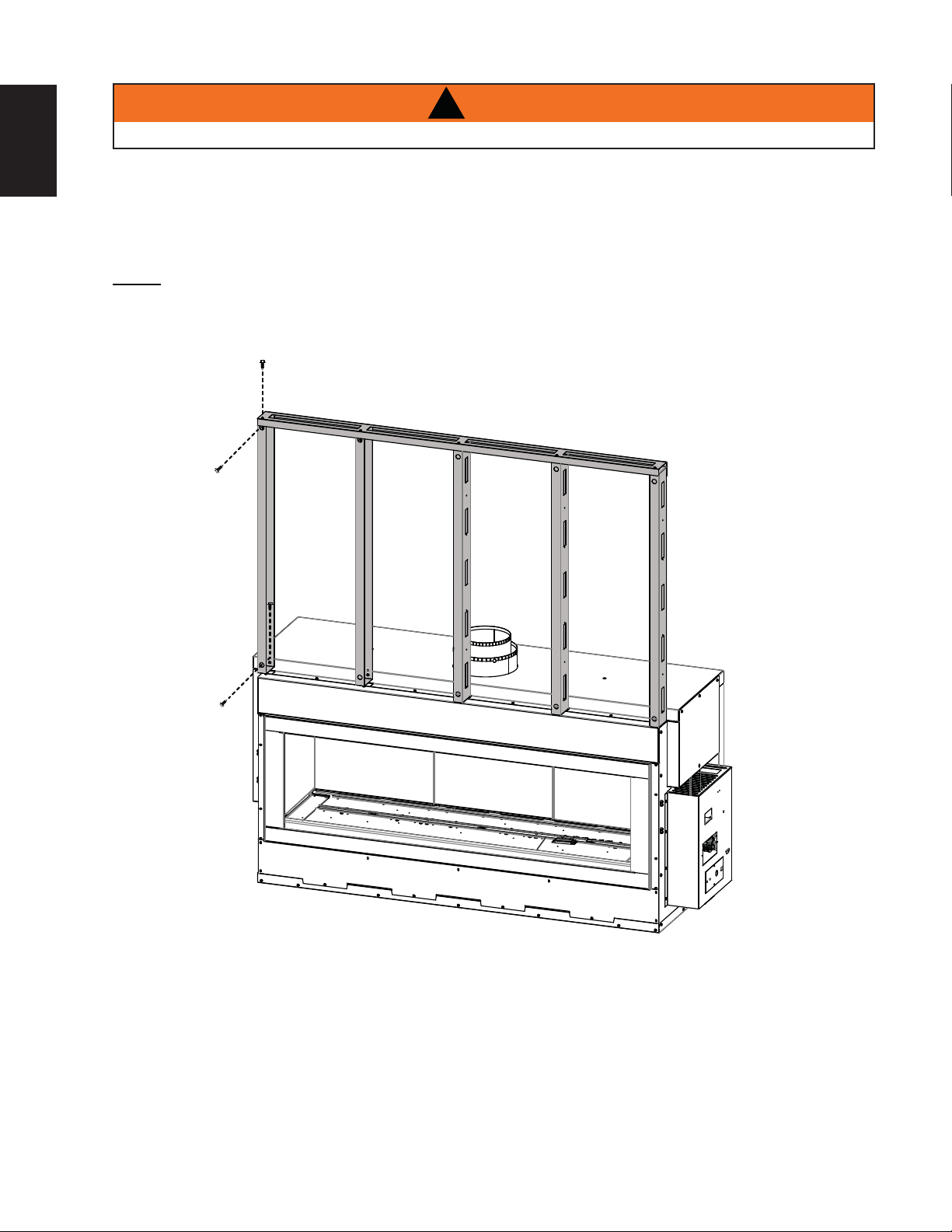
A. Erect the steel frame supplied as illustrated.
B. Attach the metal studs (5) to the appliance as illustrated and secure with 2 screws each.
C. Set the header onto the studs as illustrated and secure with 2 screws each.
NOTE: For heavier fi nishing materials such as marble, we recommend adding extra support to the
frame. Ensure there is adequate fl oor support for the appliance and fi nishing material.
W415-1334 / 06.10.14
Page 27
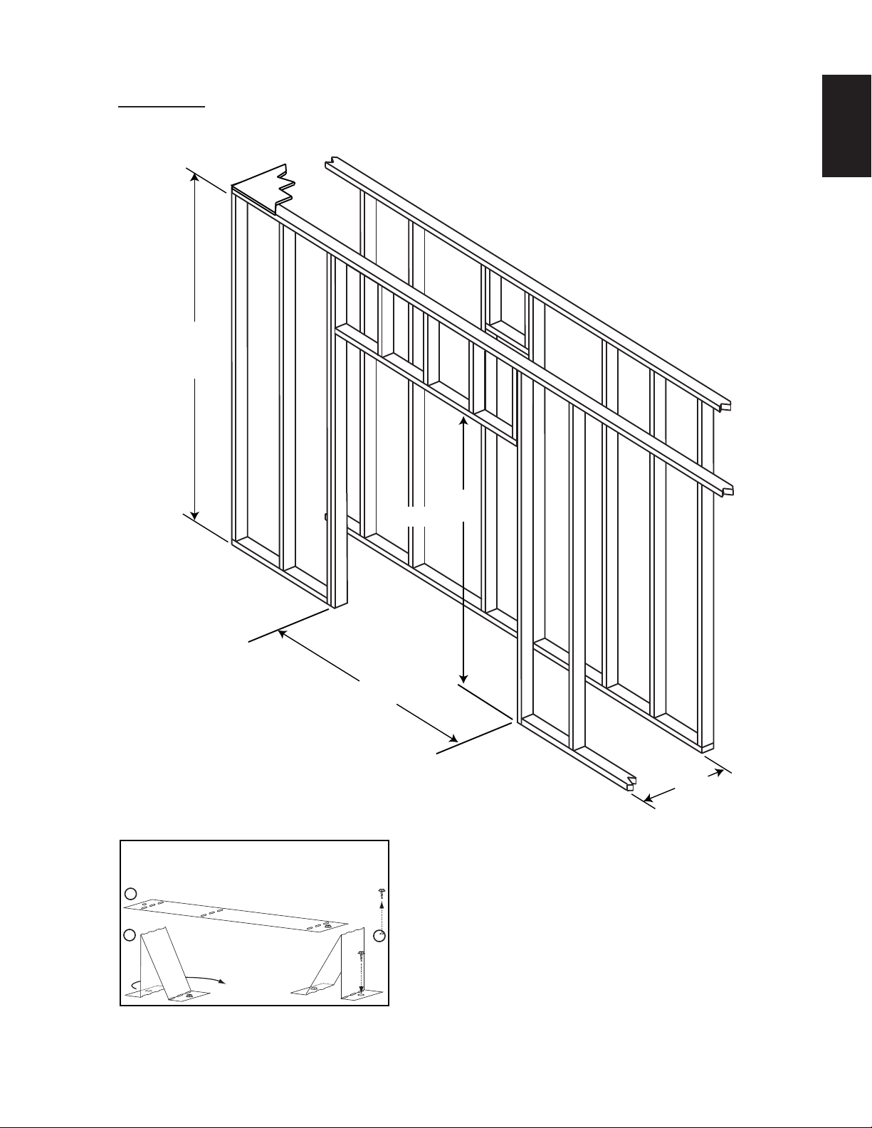
27
* When constructing the enclosure allow for fi nishing material thickness to maintain clearances.
IMPORTANT: Before fi nishing in the appliance test the operation using the remote control, cycling it
through all of its different modes, see “OPERATION” section. Should trouble shooting be required,
access to the controls can be made through the pre-fi nishing access panel.
96”
(2438mm)
MINIMUM
EN
(1956mm)
81”
(2057mm)
This appliance is
supplied with two stand-offs.
For convenience the stand-offs
have been shipped fl at and located
on the back of the appliance. Before framing
ensure the stand-offs are bent up and screwed into
place ensuring a height of 3” (76mm).
STAND-OFFS
Bend and secure the stand-offs as
A
illustrated:
77”
27”
(686mm)*
B
C
W415-1334 / 06.10.14
Page 28
28
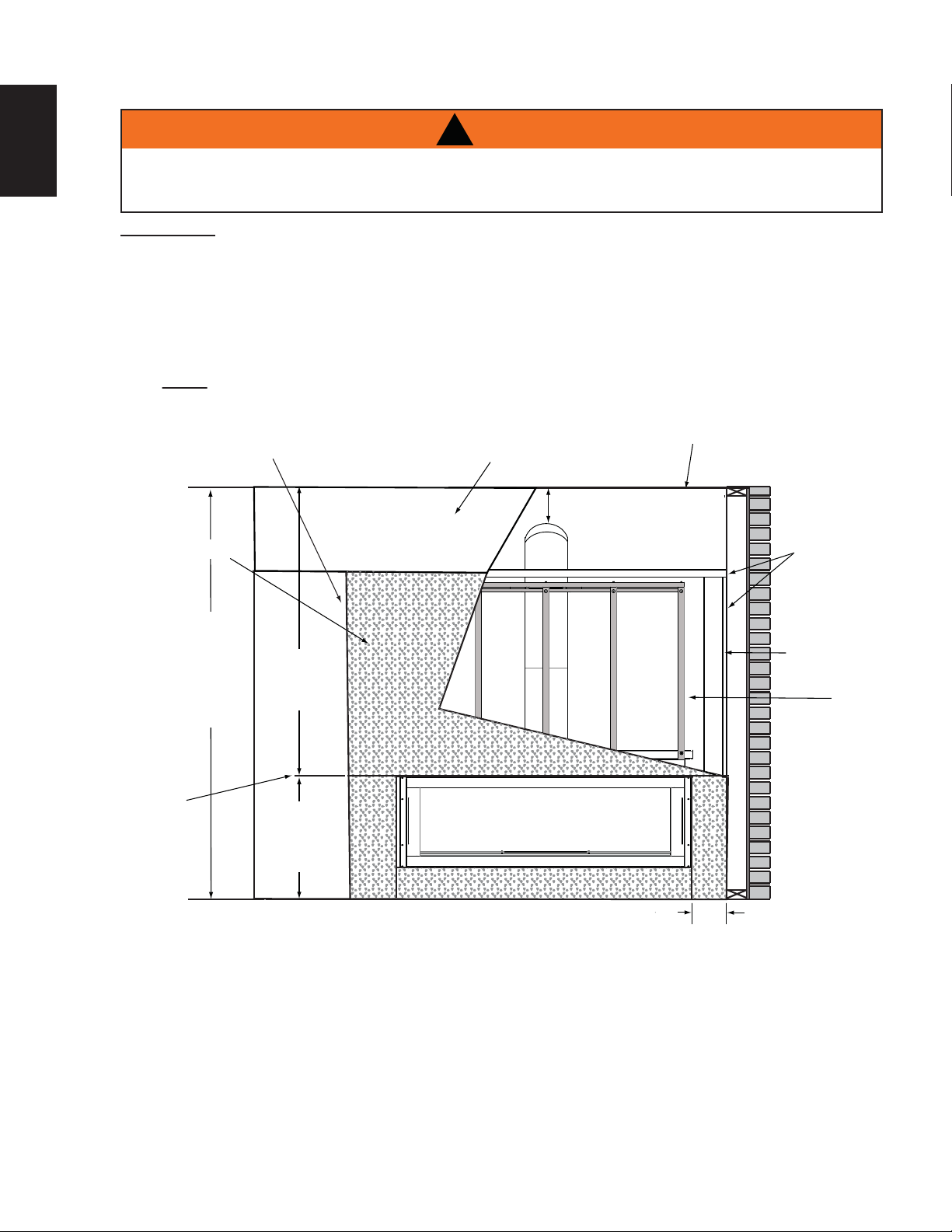
5.1 MINIMUM CLEARANCE TO COMBUSTIBLE ENCLOSURES
EN
!
WARNING
THE FRONT OF THE APPLIANCE MUST BE FINISHED WITH ANY NON-COMBUSTIBLE MATERIALS
SUCH AS BRICK, MARBLE, GRANITE, ETC., AS LONG AS THESE MATERIALS NEVER OVERHANG
INTO THE APPLIANCE OPENING.
IMPORTANT: The LHD62 requires a minimum inside enclosure height of 96” (2.4m), measured from the
bottom of the appliance. For temperature requirements, this area must be left unobstructed. It is recommended
that the enclosure be ventilated at the top and bottom to circulate the hot air.
Before fi nishing in the appliance test the operation using the remote control, cycling it through all of its different
modes, see “OPERATION” section. Check pressure readings, see “PILOT BURNER ADJUSTMENT” section.
Once fi nished in, access to the control components can only be done through the inside of the appliance.
NOTE: JOINT COMPOUNDS AND TAPES
THA T ARE RESILIENT TO HEA T AND
CRACKING SHOULD BE USED WHEN
TAPING AND MUDDING SEAMS.
NON-COMBUSTIBLE
COMBUSTIBLE
7” (178mm)
MINIMUM
TOP OF
ENCLOSURE
COMBUSTIBLE
96”
(2438mm)
MINIMUM
ENCLOSURE
HEIGHT
TOP OF
APPLIANCE
OPENING
* Within the appliance enclosure a minimum 7” (178mm) clearance between the top of the vent pipe and
combustible materials is required. All other clearances within the enclosure, including where the vent pipe exits
the enclosure are subject to 2” (51mm) to the sides and bottom and 3” (76mm) to the top for horizontal and 1”
(25mm) for vertical.
68”
(1727mm)
MINIMUM
28”
(711mm)
MINIMUM
9”
(228mm)
TO SIDEWALL
DRYWALL
STEEL
STUD
FRAME
** See venting section.
W415-1334 / 06.10.14
Page 29
TOP OF ENCLOSURE
(COMBUSTIBLE)
NON-COMBUSTIBLE
COMBUSTIBLE
29
EN
STEEL
STUD
FRAME
NON-COMBUSTIBLE
(1727mm)
MINIMUM
96”
(2438mm)
MINIMUM
ENCLOSURE
HEIGHT
68”
CEILING
MINIMUM 7”
(178mm)
3”
(76mm)
2” (51mm)
FIRESTOP
ASSEMBLY
84” (2134mm)
PLUS RISE **
0” (0m) IF NONCOMBUSTIBLE
FINISHING IS USED
SUCH AS BRICK
AND STONE.
MINIMUM
TOP OF
APPLIANCE
OPENING
* Within the appliance enclosure a 7” (178mm) clearance between the top of the vent pipe and combustible
materials is required. All other clearances within the enclosure, including where the vent pipe exits the
enclosure are subject to 2” (51mm) to the sides and bottom and 3” (76mm) to the top for horizontal and 1”
(25mm) for vertical.
** See venting section.
IMPORTANT: THE FIRESTOP ASSEMBLY PROVIDED MUST BE USED WHEN THE VENT PIPES PASS
THROUGH ANY WALL OR ARE TERMINATED HORIZONTALLY.
28”
(711mm)
MINIMUM
3”
(76mm)
W415-1334 / 06.10.14
Page 30
30
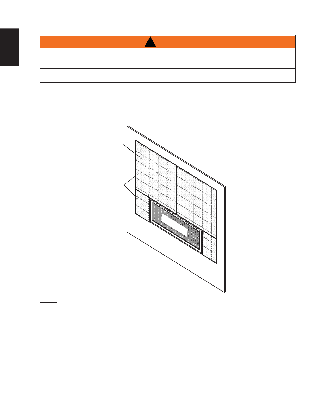
5.2 INSTALLING NON-COMBUSTIBLE BOARD
EN
A NON-COMBUSTIBLE FINISHING MATERIAL BORDER, SUCH AS BRICK, MARBLE, GRANITE, ETC.
IS REQUIRED. FINISHING WITH JUST NON-COMBUSTIBLE BOARD TO THE SIDES AND TOP OF THE
APPLIANCE IS NOT ALLOWED.
THE SURFACE ABOVE THE APPLIANCE GETS VERY HOT. IF PROPER FINISHING MATERIALS ARE
NOT USED, CRACKING CAN OCCUR.
!
WARNING
If using non-combustible board the entire surface
must be covered with a non-combustible decorative
fi nish such as brick, marble, granite, etc.
SUPPLIED NON-
COMBUSTIBLE
BOARD
NON-
COMBUSTIBLE
BOARD
REQUIRED
It is not required to cover the entire surface with a
non-combustible decorative fi nishing material if using
a full sheet of non-combustible board where required.
However, a minimum of one course of tile is required
to border the sides and top around the door opening.
The larger the tile size, the better.
SAFETY BARRIER
NOTE: Keep the securing screws for the non-combustible board a minimum of 6” (152mm) from the side and
top of the door opening. This will allow for any slight movement in the normal operation of the appliance.
Joint Compound where required
Joint compounds such as Durabond 90 and tapes that are resilient to heat and cracking should be used when
taping and mudding seams.
Setting tiles and grouting
We recommend you use tiles with a dry butt joint to be installed using a two-part mortar with an acrylic latex
additive, such as Mapei Kerabond/Kerlastic, to allow for slight movement in the normal operation of the appliance.
If grout is used between the tiles, a polymer-based grout, such as Mapei Ultracolour plus, is recommended.
Primer/Paint
For a painted surface, use a 100% acrylic latex primer and fi nish coat. Light coloured paints may discolour.
W415-1334 / 06.10.14
Page 31

5.3 NON-COMBUSTIBLE FINISH MATERIAL
31
WARNING: If greater projections are desired, increase the clearance to the sides and top by 2” (51mm) for
every additional 1” (25mm) of projection. If using an optional surround, then 2” (51mm) clearance from the
surround is required before projecting out a maximum 2” (51mm). If greater projections are desired, increase
the clearance from the surround by 2” (51mm) for every 1” (25mm) of additional projection.
A
SAFETY BARRIER
A
4”
(102mm)
6” (152mm)
4” (102mm)
2” (51mm)
0” (0mm)
3” (76mm)
2” (51mm)
TOP OF
APPLIANCE
EN
SAFETY
BARRIER
SECTION A - A
DOOR
71.5B
W415-1334 / 06.10.14
Page 32

32
5.5 MINIMUM COMBUSTIBLE MANTEL CLEARANCES
EN
!
WARNING
RISK OF FIRE, MAINTAIN ALL SPECIFIED AIR SPACE CLEARANCES TO COMBUSTIBLES. FAILURE
TO COMPLY WITH THESE INSTRUCTIONS MAY CAUSE A FIRE OR CAUSE THE APPLIANCE TO
OVERHEAT. ENSURE ALL CLEARANCES (I.E. BACK, SIDE, TOP, VENT, MANTEL, FRONT, ETC.) ARE
CLEARLY MAINTAINED.
WHEN USING PAINT OR LACQUER TO FINISH THE MANTEL, THE PAINT OR LACQUER MUST BE
HEAT RESISTANT TO PREVENT DISCOLOURATION.
73.1
Combustible mantel clearance can vary according to the mantel depth. Use the graph to help evaluate the
clearance needed.
22
20
18
+
0
16
(
$
14
,
1
12
*
7
10
+
(
/
( " )
7
8
6
E
D
C
B
4
0
34 7
12 56
MANTEL DEPTH
89
( " )
TOP OF
OPENING
MANTEL DIMENSIONS
Ref Height Depth
A 28” (711mm)
B 12” (305mm) 2” (51mm)
C 14” (356mm) 4” (102mm)
D 16” (406mm) 6” (152mm)
E 18” (457mm) 8” (203mm)
A
W415-1334 / 06.10.14
Page 33

6.0 FINISHING
33
!
WARNING
RISK OF FIRE!
NEVER OBSTRUCT THE FRONT OPENING OF THE APPLIANCE.
THE FRONT OF THE APPLIANCE MUST BE FINISHED WITH ANY NON-COMBUSTIBLE MATERIALS
SUCH AS BRICK, MARBLE, GRANITE, ETC., PROVIDED THAT THESE MATERIALS DO NOT GO
BELOW THE SPECIFIED DIMENSION AS ILLUSTRATED.
DO NOT STRIKE, SLAM OR SCRATCH GLASS. DO NOT OPERATE APPLIANCE WITH GLASS
REMOVED, CRACKED, BROKEN OR SCRATCHED.
FACING AND/OR FINISHING MATERIAL MUST NEVER OVERHANG INTO THE APPLIANCE OPENING.
THE GLASS DOOR ASSEMBLY IS DESIGNED TO PIVOT FORWARD WHEN RELIEVING EXCESS
PRESSURE THAT MIGHT OCCUR. FINISHING OR OTHER MATERIALS MUST NOT BE LOCATED IN
THE OPENING SURROUNDING THE DOOR AS THIS WILL INTERFERE WITH THE DOORS ABILITY TO
RELIEVE THE PRESSURE.
72.6
6.1 SAFETY SCREEN AND DOOR REMOVAL / INSTALLATION
!
WARNING
GLASS MAY BE HOT, DO NOT TOUCH GLASS UNTIL COOLED.
EN
THE DOOR LATCHES ARE PART OF A SAFETY SYSTEM AND MUST BE PROPERLY ENGAGED. DO
NOT OPERATE THE APPLIANCE WITH LATCHES DISENGAGED.
FACING AND/OR FINISHING MATERIALS MUST NOT INTERFERE WITH AIR FLOW THROUGH AIR
OPENINGS, LOUVRES OPENINGS, OPERATION OF LOUVRES OR DOORS OR ACCESS FOR
SERVICE. OBSERVE ALL CLEARANCES WHEN APPLYING COMBUSTIBLE MATERIALS.
BEFORE DOOR IS REMOVED TURN THE APPLIANCE OFF AND WAIT UNTIL APPLIANCE IS COOL TO
THE TOUCH. DOORS ARE HEAVY AND FRAGILE SO HANDLE WITH CARE.
75.1
W415-1334 / 06.10.14
Page 34

34
A barrier designed to reduce the risk of burns from the hot viewing glass is provided with the
appliance and shall be installed.
EN
NOTE: It is recommended to perform this task with two people
A. There are 8 spring latches securing the main
glass door, 4 of those latches are across the
top and 4 along the bottom. To access these
latches, the safety barrier screen and door trim
must be removed.
B. Using the tool provided, pull the latch forward
and upwards, out of the slot in the door for the
top latches and reverse for the bottom latches,
as shown. Repeat 7 times. Ensure to keep one
hand on the door at all times, to prevent it from
falling on the fl oor.
C. When all 8 latches have been released pull the
door forward and off of the appliance.
D. Reverse these steps to reinstall the safety
screen and door trim.
THE 8 LATCHES ARE SHOWN IN THE ILLUSTRATION BELOW.
IMPORTANT: Once latches are engaged,
test that the door is secure and will not
fall forward before letting go.
LATCHESMAGNETS
W415-1334 / 06.10.14
Page 35

6.2 GLASS MEDIA INSTALLATION
!
WARNING
CLEAN THE GLASS MEDIA PRIOR TO INSTALLATION. BEFORE APPLYING THE CLEANED GLASS, ENSURE
THAT IT IS DRY.
DO NOT CHANGE OR SUBSTITUTE THE GLASS MEDIA MATERIAL PROVIDED WITH THIS APPLIANCE. IF
REPLACING, USE ONLY THE REPLACEMENT GLASS MEDIA AVAILABLE FROM YOUR AUTHORIZED
DEALER / DISTRIBUTOR.
DO NOT PLACE ANY MEDIA (GLASS OR VERMICULITE) IN OR AROUND THE PILOT OPENING. THIS WILL
INTERFERE WITH THE PILOT OPERATION
Evenly spread the glass media onto the media tray, ensuring no glass media falls into the pilot opening. If this
happens, insert a clean bag into your vacuum cleaner and vacuum out the glass media. Replacement glass
can be purchased from your local authorized dealer / distributor.
NOTE: Do not use more media than what was supplied with the appliance.
CLEANING GLASS MEDIA
Glass media may have a fi ne oil residue that needs to be cleaned prior to installation. Clean the glass with mild
dish soap, drain, rinse thoroughly and dry before placing around the burner.
74.2C
NOTE: A thin layer of glass media may cover the media tray and burner trough. Do not cover the
burner at the pilot opening.
35
EN
COMBUSTION
AIR OPENING
PILOT OPENING
BURNER
TROUGH
MEDIA TRAY
NOTE: DO NOT PLACE MEDIA IN THE GAP AT THE REAR OF THE FIREBOX, BELOW
PORCELAIN PANELS. THIS IS THE COMBUSTION AIR OPENING, BLOCKING IT WILL RESULT IN
POOR PERFORMANCE.
W415-1334 / 06.10.14
Page 36

EN
36
6.4 OPTIONAL ROCK PLACEMENT
Randomly place the refractory rocks onto the media tray, around, but not on the burner ports or pilot mesh.
Follow the instructions provided with RK62.
6.5 LOGO PLACEMENT
SAFETY BARRIER
LOGO
7.0 ELECTRICAL CONNECTION
!
WARNING
DO NOT USE THIS APPLIANCE IF ANY PART HAS BEEN UNDER WATER. CALL A QUALIFIED
SERVICE TECHNICIAN IMMEDIATELY TO HAVE THE APPLIANCE INSPECTED FOR DAMAGE TO THE
ELECTRICAL CIRCUIT.
RISK OF ELECTRICAL SHOCK OR EXPLOSION. DO NOT WIRE 110V TO THE VALVE OR TO THE
APPLIANCE WALL SWITCH. INCORRECT WIRING WILL DAMAGE CONTROLS.
ALL WIRING SHOULD BE DONE BY A QUALIFIED ELECTRICIAN AND SHALL BE IN COMPLIANCE
WITH LOCAL CODES. IN THE ABSENCE OF LOCAL CODES, USE THE CURRENT CSA22.1 CANADIAN
ELECTRIC CODE IN CANADA OR THE CURRENT NATIONAL ELECTRIC CODE ANSI/NFPA NO. 70 IN
THE UNITED STATES.
ALWAYS LIGHT THE PILOT WHETHER FOR THE FIRST TIME OR IF THE GAS SUPPLY HAS RAN OUT,
WITH THE GLASS DOOR OPENED OR REMOVED.
7.1 HARD WIRING CONNECTION
It is necessary to hard wire this appliance.
Permanently framing the appliance with an enclosure, requires the appliance junction box to be hard wired.
This appliance must be electrically connected and grounded in accordance with local codes. In the absence
of local codes, use the current CSA C22.1 Canadian electrical code in Canada or the ANSI/NFPA 70-1996
national electrical code in the United States.
W415-1334 / 06.10.14
69.2
Page 37

7.2 RECEPTACLE WIRING DIAGRAM
(4) AA Batteries
37
EN
PRE-FINISHING
ACCESS PANEL
ELECTRICAL COVER
CABLE CONNECTOR
7.3 BATTERY HOLDER INSTALLATION
A. The battery holder must be
located within 8 feet of this side
of the appliance and must be
accessible for programming the
remote.
B. Install 4 AA batteries, ensure
that the positive and negative
ends correspond with those
identifi ed in the battery holder.
C. Install the battery holder into
a standard electrical switch
box. Determine an appropriate
location and install the electrical
box.
L1
L2
PLASTIC BUSHING
NOTE: Ensure the 3 position slider
switch is in the “REMOTE” position
(middle).
RESET/PROGRAM BUTTON (PRG)
(4) AA Batteries
W415-1334 / 06.10.14
Page 38

38
7.4 SCHEMATIC
EN
!
WARNING
DO NOT WIRE 110 VOLTS TO THE VALVE OR WALL SWITCH.
PILOT
BLOWER
NIGHT
LIGHT
W190-0048 (RECEIVER)
RESET
BUTTON
WITH RESET BUTTON
BATTERY HOLDER COMPLETE
W415-1334 / 06.10.14
Page 39

8.0 OPERATION
39
8.1 GENERAL TRANSMITTER LAYOUT
Key Lock
Low Battery Alarm
Low battery alarm
Transmission
Room
Temperature
CPI mode
Flame ON
(NOT AVAILABLE WITH THIS MODEL)
Blower
Night Light
8.2 INITIALIZING THE TRANSMITTER/BATTERY HOLDER FOR THE FIRST TIME
EN
A. Install the 4 AA batteries into the Profl ame 2 battery holder, note the polarity of the batteries and insert
as indicated on the cover (+/-).
B. Ensure the 3 position slider switch is switched to the “REMOTE” position (middle position).
C. Press the reset/programming button, use a small object such as a paper clip in order to reach the
button marked PRG, as shown in the illustration below.
D. The battery holder will beep 3 times to indicate that it’s ready to synchronize with the transmitter.
E. Install the 3 AAA batteries into the transmitter, as shown in the photograph below, then press the ON
button, The battery holder will beep 4 times to indicate that the transmitter’s command is accepted.
NOTE: THE INITIALIZING PROCESS MUST BE COMPLETED WITHIN 10 SECONDS OF PRESSING THE
RESET/PROGRAM BUTTON (PRG).
TRANSMITTER
BATTERY HOLDER
SLIDER SWITCH
RESET/PROGRAM
BUTTON (PRG)
(4) AA Batteries
W415-1334 / 06.10.14
Page 40

40
A
8.3 TEMPERATURE DISPLAY
EN
8.4 FLAME HEIGHT
. With the system in the “OFF” position, press the
Temperature Key and the Mode Key at the same
time to change from degrees F to C.
B. Look at the LCD screen on the Transmitter to
verify that a C or F is visible to the right of the
Room Temperature display.
The remote control has six (6) fl ame levels. With the
system on and the fl ame level at the maximum, press
the Down Arrow Key once and it will reduce the fl ame
height by one step until the fl ame is turned off.
The Up Arrow Key will increase the fl ame height each
time it is pressed. If the Up Arrow Key is pressed while
the system is on but the fl ame is off, the fl ame will
come on the high position. A single “beep” will confi rm
reception of the command.
73
76
OFF
FLAME OFF
76
°F
°F
°F
°C
23
35.5A
°F
76
FLAME AT LEVEL 1
°F
76
Hi
FLAME AT LEVEL 5 FLAME AT “HI” LEVEL 6
35.8A
8.5 NIGHT LIGHT DIMMER CONTROL
The auxiliary function controls the Night Light
dimmable control.
A. Use the Mode Key to guide you to the Night
Light icon.
B. The intensity of the output can be adjusted
through 6 levels. Use the UP/DOWN arrow
keys to adjust the output level. A single beep will
confi rm reception of the command.
TM
with
76
OFF
°F °F
76
35.21
W415-1334 / 06.10.14
Page 41

8.6 CONTINUOUS PILOT / INTERMITTENT PILOT (CPI / IPI) SELECTION
e
A. Use the Mode Key to guide you to the CPI mode
icon. Transmitter in the OFF position.
B. Press the UP/DOWN to switch between IPI and
CPI modes. A single BEEP will confi rm reception
of the command.
Note: If the system is equipped with a CPI/IPI
toggle switch, set the CPI/IPI to CPI position to
enable remote CPI operation. If the switch is set
to IPI then it will only work in IPI regardless of
what is set on the remote control handset.
8.7 KEY LOCK
This function will lock the keys to avoid unsupervised operation.
76
IPI
°F °F
76
CPI
35.22
41
EN
°F
A. Press the MODE and UP keys at the same time.
B. To de-activate this function, press the MODE and UP keys at the same time.
8.8 LOW BATTERY / MANUAL BYPASS
The life span of the remote batteries depends on various factors: quality of the
batteries, the number of ignitions, the number of changes to the room thermostat set
point, etc.
When the transmitter batteries are low, a Battery Icon will appear on the LCD
display before all battery power is lost. When the batteries are replaced this icon will
disappear.
Not applicable when plugged into 110V.
When the batteries are low, no “beep” will be emitted from the receiver when it
receives an ON/OFF command. This in an alert for the receiver that there’s low battery. When the batteries ar
replaced the “beep” will be emitted from the receiver when the ON/OFF key is pressed.
If the batteries in the battery holder or transmitter are low, the appliance can be turned on manually by sliding
the three position slider switch on the battery holder to the “ON” position. This will bypass the remote control
feature and the appliance main burner will come on. Likewise, if you want to manually turn the appliance off,
slide the switch to the ‘OFF’ position.
76
35.10A
°F
76
35.23
W415-1334 / 06.10.14
Page 42

42
9.0 OPERATING INSTRUCTIONS
EN
!
WARNING
IF YOU DO NOT FOLLOW THESE INSTRUCTIONS EXACTLY, A FIRE OR EXPLOSION MAY RESULT
CAUSING PROPERTY DAMAGE, PERSONAL INJURY OR LOSS OF LIFE.
NEVER LEAVE CHILDREN OR OTHER AT RISK INDIVIDUALS ALONE WITH THE APPLIANCE.
ALWAYS LIGHT THE PILOT WHETHER FOR THE FIRST TIME OR IF THE GAS SUPPLY HAS RUN OUT WITH
THE GLASS DOOR OPENED OR REMOVED.
Ensure that a continuous gas flow is at the burner before installing the door. When lit for the first time, the
appliance will emit an odor for a few hours. This is a normal temporary condition caused by the “burn-in” of
paints and lubricants used in the manufacturing process and will not occur again. After extended periods of
non-operation such as following a vacation or a warm weather season, the appliance may emit a slight odor
for a few hours. This is caused by dust particles in the heat exchanger burning off. In both cases, open a
window to sufficiently ventilate the room.
FOR YOUR SAFETY READ BEFORE LIGHTING:
A. This appliance is equipped with an ignition device which automatically lights the pilot. Do not try to light by hand.
B. Before operating smell all around the appliance area for gas and next to the floor because some gas is heavier than
air and will settle on the floor.
C. Do not use this appliance if any part has been under water. Immediately call a qualified service technician to inspect
the appliance and replace any part of the control system and any gas control which has been under water.
WHAT TO DO IF YOU SMELL GAS:
Turn off all gas to the appliance.
Open windows.
Do not try to light any appliance.
Do not touch any electric switch; do not use any phone
in your building.
Immediately call your gas supplier from a neighbor's
phone. Follow the gas supplier's instructions.
If you cannot reach your gas supplier, call the fire
department.
LIGHTING INSTRUCTIONS
A. Stop! Read the above safety information on this label.
B. Remove batteries from transmitter.
C. Turn off all electric power to the appliance.
D. This appliance is equipped with an ignition device which automatically lights the pilot. Do not try to light the pilot by
hand.
E. Open the glass door.
F. Turn manual shutoff valve clockwise to off. Located behind the access panel.
G. Wait five (5) minutes to clear out any gas. If you smell gas including near the floor, STOP! Follow “B” in the above
safety information on this label. If you don’t smell gas go to the next step.
H. Turn manual shutoff valve counter-clockwise to on.
I. Close the glass door.
J. Turn on all electric power to the appliance and re-install batteries into the transmitter.
K. Push the “ON” button on the transmitter. You should here an audible beep from the receiver
which indicates communication. (Refer to Appliance Operations for remote activation).
TO TURN OFF GAS
A. Turn off all electric power to the appliance if service is to be performed.
B. Access door inside the firebox must be removed to access the manual shutoff valve.
C. If alternate shut-off valve was installed it can be shutoff instead of going through the appliance to access
the appliance shut off valve.
47.4
W415-1334 / 06.10.14
Page 43

10.0 ADJUSTMENT
10.1 RESTRICTING VERTICAL VENTS
43
Vertical installations may display a very active fl ame. If this appearance is not desirable, the vent exit must
be restricted using a restrictor vent kit. Refer to “ACCESORIES” in the “REPLACEMENTS” section for the
appropriate kit. This will reduce the velocity of the exhaust gases, slowing down the fl ame pattern and creating
a more traditional gentle fl ame appearance. Specifi c instructions are included with the kit.
10.2 PILOT BURNER ADJUSTMENT
Adjust the pilot screw to provide properly sized fl ame. Turn in a
clockwise direction to reduce the gas fl ow.
Check Pressure Readings:
Inlet pressure can be checked by turning screw (A) counter-
clockwise 2 or 3 turns and then placing pressure gauge tubing
over the test point. Gauge should read as described on the chart
below. Check that main burner is operating on “HI”.
Outlet pressure can be checked the same as above using
screw (B). Gauge should read as described on the chart
below. Check that main burner is operating on “HI”.
AFTER TAKING PRESSURE READINGS, BE SURE TO
TURN SCREWS CLOCKWISE FIRMLY TO RESEAL. DO
NOT OVERTORQUE.
Leak test with a soap and water solution.
Prior to pilot adjustment, ensure that the pilot assembly
has not been painted. If overspray or painting of the pilot
assembly has occurred remove the paint from the pilot
assembly, or replace. Fine emery
cloth or sandpaper can be used to
Pressure
remove the paint from the pilot hood,
electrode and fl ame sensor.
Inlet
Outlet
10.3 VENTURI ACCESS
(9.5mm - 12.7mm)
Natural Gas
(inches)
7"
(MIN. 4.5")
3.5"
A
ELECTRODE
3/8” - 1/2”
FLAME
SENSOR
Natural Gas
(millibars)
17.4mb
(MIN. 11.2mb)
8.7mb
77.3
B
PILOT SCREW
PILOT
BURNER
FLAME MUST ENVELOP
UPPER 3/8” (9.5mm) TO 1/2”
(12.7mm) OF FLAME SENSOR
Propane
(inches)
13"
(MIN. 11")
10"
39.1C
Propane
(millibars)
32.4mb
(MIN. 27.4mb)
24.9mb
EN
Prior to installation.
A. Follow the “DOOR REMOVAL” proccess and then follow the media removal instructions located under
“MAINTENANCE”
B. Remove the front access cover plate from the appliance.
C. Access the venturi housing and remove the 2 screws securing the cover plate and gasket.
D. Losen the screw on the air shutter and adjust accordingly, refer to the “VENTURI ADJUSTMENT”
section for more detail.
After installation.
A. Follow the “DOOR REMOVAL” proccess.
B. Follow the media removal instructions located under the “MAINTENANCE” section.
C. Refer to the “BURNER REMOVAL” section then continue with the following instructions.
D. Access the venturi housing and remove the 2 screws, as above.
E. Losen the screw on the air shutter and adjust accordingly, refer to the “VENTURI ADJUSTMENT”
section for more detail.
If access to the venturi housing is necessary BEFORE INSTALLATION, remove the pre-fi nishing access panel.
The access panel must be re-installed before operating the appliance.
Continued on next page
W415-1334 / 06.10.14
Page 44

EN
R
44
PRE-FINISHING
ACCESS PANEL
Before fi nishing in the appliance test the operation using the remote control, cycling it through all of its different
modes, see “OPERATION” section. Once fi nished in, access to the control components can only be done
through the inside of the appliance.
NOTE: Control module ON/OFF switch should always be in the “ON” position. If for any reason the
module is turned “OFF”, the components plugged into the module won’t have power.
10.4 VENTURI ADJUSTMENT
This appliance has an air shutter that has been factory set open according
to the chart below:
Regardless of venturi orientation, closing the air shutter will cause a more
yellow flame, but can lead to carboning. Opening the air shutter will cause a
more blue flame, but can cause flame lifting from the burner ports. The
flame may not appear yellow immediately; allow 15 to 30 minutes for the
final flame colour to be established.
AIR SHUTTER ADJUSTMENT MUST ONLY BE DONE BY A QUALIFIED
INSTALLER!
10.5 FLAME CHARACTERISTICS
It’s important to periodically perform a visual check of the pilot and burner fl ames. Compare them to the
illustration provided. If any fl ames appear abnormal call a service person.
VENTURI ADJUSTMENT CHART
FUEL LHD62
NG 1/32 (0.8mm)
LP 1/2 (13mm)
ELECTRODE
(9.5mm - 12.7mm)
3/8” - 1/2”
FLAME
SENSOR
VENTURI
BURNER
AIR
SHUTTER
OPENING
ORIFICE
49.1
PILOT
BURNER
W415-1334 / 06.10.14
FLAME MUST ENVELOP
UPPER 3/8” (9.5mm) TO 1/2”
(12.7mm) OF FLAME SENSO
54.1B
Page 45

11.0 MAINTENANCE
45
MAINTENANCE
MAINTENANCE
MAINTENANCE
TURN OFF THE GAS AND ELECTRICAL POWER BEFORE SERVICING THE APPLIANCE.
APPLIANCE MAY BE HOT, DO NOT SERVICE UNTIL APPLIANCE HAS COOLED.
DO NOT USE ABRASIVE CLEANERS.
DO NOT PAINT THE PILOT ASSEMBLY.
CAUTION: Label all wires prior to disconnection when servicing controls. Wiring errors can cause improper
and dangerous operation. Verify proper operation after servicing. This appliance and its venting system
should be inspected before use and at least annually by a qualifi ed service person. The appliance area must
be kept clear and free of combustible materials, gasoline or other fl ammable vapors and liquids. The fl ow of
combustion and ventilation air must not be obstructed.
A. In order to properly clean the burner and pilot assembly, remove the logs, rocks and/or glass to
expose both assemblies.
B. Keep the control compartment, media, burner, air shutter opening and the area surrounding the logs
clean by vacuuming or brushing, at least once a year.
C. Check to see that all burner ports are burning. Clean out any of the ports which may not be burning or
are not burning properly.
D. Check to see that the pilot fl ame is large enough to engulf the fl ame sensor and/or thermocouple /
thermopile as well as reaches the burner.
E. Replace the cleaned logs, rocks or glass. Failure to properly position the media may cause carboning
which can be distributed in the surrounding living area.
F. Check to see that the main burner ignites completely on all openings when turned on. A 5 to 10
second total light-up period is satisfactory. If ignition takes longer, consult your local authorized dealer /
distributor.
G. Check that the gasketing on the sides, top and bottom of the door is not broken or missing. Replace if
necessary.
H. If for any reason the vent air intake system is disassembled, re-install and re-seal per the instructions
provided for the initial installation.
I. Cleaning the safety barrier may be necessary due to excessive lint / dust from carpeting, pets, etc.
simply vacuum using the brush attachment.
J. Ensure the pressure relief system performs effectively. Check that the gasket is not worn or damaged.
Replace if necessary.
!
WARNING
40.1D
11.1 ANNUAL MAINTENANCE
EN
!
WARNING
THE FIREBOX BECOMES VERY HOT DURING OPERATION. LET THE APPLIANCE COOL
COMPLETELY OR WEAR HEAT RESISTANT GLOVES BEFORE CONDUCTING SERVICE.
NEVER VACUUM HOT EMBERS.
DO NOT PAINT THE PILOT ASSEMBLY.
• This appliance will require maintenance which should be planned on an annual basis.
• Service should include cleaning, battery replacement, venting inspection and inspection of the burner,
media and fi rebox. Refer to the door removal section and remove the door as instructed.
• Carefully remove media if necessary (logs, glass, brick panels etc).
• Using a vacuum with a soft brush attachment, gently remove any dirt, debris or carbon build up from the
logs, fi rebox and burner. For glass media, follow the installation instructions for pre-cleaning.
• Also gently remove any build-up on the pilot assembly including, if equipped; thermopile, thermocouple,
fl ame sensor and igniter.
Scotch-Brite™ scrubbing pad to remove any oxides.
soft brush attachment.
NOTE: The fl ame sensor may require to be cleaned using a fi ne steel wool or
Clean the pilot assembly using a vacuum with a
It is important that the pilot assembly is not painted.
W415-1334 / 06.10.14
Page 46

46
• Inspect all accessible gaskets and replace as required.
• Access the blower, if equipped and clean using a soft brush and vacuum.
• Re-assemble the various components in reverse order.
EN
11.2 CONTROL ACCESS
• Inspect the relief system. The appliance relieves through the main glass door or through the fl aps on the
fi rebox top. Ensure they open freely, and close sealed.
• Check the gas control valve pilot and Hi / Lo knobs move freely (if equipped) – replace if any stiffness in
movement is experienced.
• Check for gas leaks on all gas connections up and downstream from the gas valve including the pilot tube
connections.
Once the appliance has been framed and fi nished, control access can only be achieved by removing the access
panel inside the fi rebox at the right end. The following sub sections take you through the steps of accessing the
control as if the appliance is installed.
*Prior to removing the control panel follow the “DOOR REMOVAL” proccess and then follow the media removal
instructions located under the “MAINTENANCE” section.
NOTE: IT WILL BE NECESSARY TO REPLACE THE GASKET (W290-0197) FOR THE ACCESS PLATE IF
THE UNIT HAS BEEN PREVIOUSLY OPERATED BEFORE REMOVING THE PLATE (W290-0197).
A. Remove the media tray by removing all screws securing the front, rear and side panels.
B. Remove the rear right side and then the right side porcelain panels, follow removal instructions under
the “ PORCELAIN PANEL REMOVAL” section.
C. To access the control access remove the 12 screws securing the access plate.
D. Care should be taken to ensure avoiding damage to the gasket.
E. Reverse this process to install the control access. Ensure the access plate is well sealed to the fi replace
37.1C
11.3 MEDIA REMOVAL/REPLACEMENT
A. Glass
Insert a clean bag into your vacuum cleaner and vacuum out the glass media.
B. Rock
Carefully remove all of the rocks from the appliance.
C. Driftwood
Carefully remove all of the driftwood logs from the appliance.
D. Sand/Vermiculite
Option 1: Separate and remove the vermiculite from the sand, as best you can, remove it from the appliance.
Insert a clean bag into your vacuum cleaner and vacuum out the sand media.
Option 2: Insert a clean bag into your vacuum cleaner and vacuum out the sand and vermiculite from the
appliance, throw this media away and replace it with a new bag of sand and vermiculite.
W415-1334 / 06.10.14
RIGHT
SIDE
Page 47

11.4 BURNER REMOVAL
47
*Prior to removing the burner follow the “SAFETY SCREEN AND DOOR REMOVAL” proccess and then follow
the media removal instructions located under the “MAINTENANCE” section.
A. Remove the media tray by removing all screws securing the front, rear and side panels.
B. Remove the 8 screws that secure the burner/mesh to the appliance.
C. Carefully lift the burner mesh as well as the burner straight up through the venturi housing mesh, as
shown in the illustration below.
D. Repeat this process on the other burners, if replacement or removal is necessary.
MEDIA TRAY
BURNER MESH
BURNER
EN
VENTURI HOUSING
11.5 BURNER ASSEMBLY REMOVAL
Prior to removing the burner follow the “SAFETY SCREEN AND DOOR REMOVAL” process and then follow
the media removal instructions located under the “MAINTENANCE” section.
A. Remove the media tray by removing all screws securing the front, rear and side panels.
B. Remove the 22 screws securing the burner/mesh to the appliance.
C. Remove the rear right side and then the right side porcelain panels, follow removal instructions under
the “ PORCELAIN PANEL REMOVAL” section. To access the controls remove the 12 screws securing
the access plate. NOTE: It will be necessary to replace the gasket (W290-0197) for the access plate if
the unit has been previously operated before removing the plate.
D. Remove the pilot tube bulk head plate from the appliance by removing the two screws, on the lower
right side of the appliance. Disconnect the pilot tubing. Remove the pilot wire bulk head by removing
the two screws, then disconnect the inside wire.
E. Disconnect the fl ex connector from the valve and pivot the burner assembly up and out, ensure care is
taken when removing as to not twist or kink the gas lines.
F. Remove the burner assembly from the fi rebox, care should be taken to ensure avoiding damage to the
gasket.
W415-1334 / 06.10.14
Page 48

EN
48
11.6 NIGHT LIGHT REPLACEMENT
Your appliance came equipped with our “NIGHT LIGHT”. The light has been
pre-wired and can be controlled by remote control.
It is recommended that the NIGHT LIGHT be in the off position when the
appliance is on.
If in the event the lamp or lens needs to be replaced, follow the
instructions below.
A. Shut off the electrical supply to the fi replace.
B. Remove the four screws that secure the lens frame. This frame
retains the glass lens. The lamp can now be accessed.
NOTE: Do not handle the lamp (bulb) with bare fi ngers,
protect with a clean dry cloth.
C. The lamp will pull straight out of the socket.
Replace with Wolf Steel parts only, as lamp and lens are
special “high temperature” products.
D. When re-installing, ensure integrity of gasket seal.
THE FIREBOX MUST BE SEALED.
NOTE: Over tightening the screws could break the lens.
AMBER
SIDE UP
SCREWS
LENS ASSEMBLY
FIREBOX TOP
GASKET
LENS
FRAME
11.7 PORCELAIN PANEL REMOVAL
A. Remove the 2 screws on either top side of the rear porcelain panels.
B. Pivot the panel forwards and lift out, as shown below.
C. Remove the 4 screws on both top and bottom of the side porcelain panels
D. Pivot the panel forwards and lift out, as shown below.
11.8 DOOR LATCH REPLACEMENT
*Prior to replacing the latches follow the “DOOR REMOVAL” process and then follow the media removal
instructions located under the maintenance section.
A. Remove the media tray by removing all screws securing the front, rear and side panels.
B. For upper latches: locate the latch you need to replace, ensure to keep a grip on the latch. Begin
removing the 4 screws securing it in place from the inside of the fi rebox, pull latch forward. Install new
latch and ensure it remains secure by tightening the 4 screws.
C. For lower latches: locate the latch you need to replace, ensure to keep a grip on the latch. Begin
removing the 4 screws securing it in place from the inside of the fi rebox, pull latch forward. To install
the new latch secure the 2 rear screws prior to securing the 2 front screws.
D. Ensure proper door seal.
W415-1334 / 06.10.14
Page 49

11.9 GLASS / DOOR REPLACEMENT
49
!
WARNING
DO NOT USE SUBSTITUTE MATERIALS.
GLASS MAY BE HOT, DO NOT TOUCH GLASS UNTIL COOLED.
CARE MUST BE TAKEN WHEN REMOVING AND DISPOSING OF ANY BROKEN DOOR GLASS OR
DAMAGED COMPONENTS. BE SURE TO VACUUM UP ANY BROKEN GLASS FROM INSIDE THE
APPLIANCE BEFORE OPERATION.
DO NOT STRIKE, SLAM OR SCRATCH GLASS. DO NOT OPERATE APPLIANCE WITH GLASS
REMOVED, CRACKED, BROKEN OR SCRATCHED.
56.2
A. Place the door frame face down careful not to
scratch the paint.
B. Ensure the glass retainers are bent up prior to
replacing the glass and gasket.
C. Center the gasketed glass inside the door
frame with the thick side of the gasket
facing up.
D. Bend the glass retainers located along the edge
of the door frame over the gasket holding the
glass in place. Be careful not to break the glass.
GASKET
GLASS
RETAINERS
DOOR
FRAME
GLASS
EN
A barrier designed to reduce the risk of burns from
the hot viewing glass is provided with the appliance
and shall be installed.
11.10 CARE OF GLASS
DO NOT CLEAN GLASS WHEN HOT! DO NOT USE
ABRASIVE CLEANERS TO CLEAN GLASS.
Buff lightly with a clean dry soft cloth. Clean both sides
of the glass after the fi rst 10 hours of operation with a
recommended fi replace glass cleaner. Thereafter clean
as required. If the glass is not kept clean permanent
discoloration and / or blemishes may result.
This appliance is factory equipped with 5mm ceramic glass. Use only replacement glass available from your
Napoleon® dealer. DO NOT SUBSTITUTE MATERIALS.
11.11 CARE OF PLATED PARTS
If the appliance is equipped with plated parts, you must clean fi ngerprints or other marks from the plated
surfaces before operating the appliance for the fi rst time. Use a glass cleaner or vinegar and towel to clean.
If not cleaned properly before operating for the fi rst time, the marks can cause permanent blemishes on
the plating. After the plating is cured, the fi ngerprints and oils will not affect the fi nish and little maintenance
is required, just wipe clean as needed. Prolonged high temperature burning with the door ajar may cause
discolouration on plated parts.
NOTE: The protective wrap on plated parts is best removed when the assembly is at room
temperature but this can be improved if the assembly is warmed, using a hair dryer or similar heat
source.
!
WARNING
HOT GLASS WILL
CAUSE BURNS.
DO NOT TOUCH GLASS
UNTIL COOLED.
NEVER ALLOW CHILDREN
TO TOUCH GLASS.
5.1
5.5.1
6.1
W415-1334 / 06.10.14
Page 50

50
12.0 REPLACEMENTS
EN
Contact your dealer or the factory for questions concerning prices and policies on replacement parts. Normally
all parts can be ordered through your Authorized dealer / distributor.
FOR WARRANTY REPLACEMENT PARTS, A PHOTOCOPY OF THE
ORIGINAL INVOICE WILL BE REQUIRED TO HONOUR THE CLAIM.
When ordering replacement parts always give the following information:
• Model & Serial Number of appliance
• Installation date of appliance
• Part number
• Description of part
• Finish
* IDENTIFIES ITEMS WHICH ARE NOT ILLUSTRATED. FOR FURTHER INFORMATION, CONT ACT YOUR
AUTHORIZED DEALER.
NOTE: Care must be taken when removing and disposing of any broken glass or damaged
components. Be sure to vacuum up any broken glass from inside the appliance before operation.
!
WARNING
FAILURE TO POSITION THE PARTS
IN ACCORDANCE WITH THIS
MANUAL OR FAILURE TO USE ONLY
PARTS SPECIFICALLY APPROVED
WITH THIS APPLIANCE MAY
RESULT IN PROPERTY DAMAGE OR
PERSONAL INJURY.
41.1
W415-1334 / 06.10.14
Page 51

TO: "VALVE TRAIN ASSEMBLY"
L
8
0
0
5
7
SS
FOR REPLACEMENTS PARTS REFER
51
EN
06.04.14 / A
EMBLY
FOR REPLACEMENTS PARTS
REFER TO: "BURNER ASSEMBLY"
13.0 OVERVIEW
15
15
16
16
17
17
19
19
V ALVE TRAIN A
7
-2
1
W
14
14
13
13
REF. NO. PART NUMBER DESCRIPTION
11 W710-0063 FRONT MEDIA TRAY (LS)
12 W710-0064 FRONT MEDIA TRAY (RS)
13 W200-0403 PILOT COVER
14 W585-0804 PILOT SHIELD
15 W650-0025 TOP HEADER
16 W650-0024 STEEL STUDS (X5)
17 W290-0197 CONTROL DOOR GASKET
18 W010-2577 VALVE TRAIN ASSEMBL Y
19 W010-2850 BURNER ASSEMBLY
1
4
5
4
5
7
6
7
6
8
9
8
9
10
11
11
12
12
10
ITEMS MAY NOT APPEAR EXACTLY AS ILLUSTRATED
REF. NO. PART NUMBER DESCRIPTION
1 W500-0594 REAR PORCELAIN PANEL (X3)
2 W500-0592 SIDE PORCELAIN PANEL (X2)
3 W010-2580 DOOR ASSEMBLY
4 W010-2885 LA TCH T OO
5 N402-0001 LAMP (X2)
6 W280-0071 LENSE FRAME (X2)
7 W300-0067 CERAMIC GLASS (X2)
8 W010-2829 DOOR LATCHES (X8)
9 W710-0065 REAR MEDIA TRAY
10 W710-0047 END MEDIA TRAY (X2)
1
1
2
2
3
3
W415-1334 / 06.10.14
Page 52

52
50
0
80
C
SS
0
500
06
9
U
E
1
55
00
1
O
U
U
G
2
2
0
00
0
OU
U
C
O
E
3
3
350
0
6
C
C
OUS
G
60
0006
U
C
C
E
5
0
0
8
9
O
OUS
G
6
05
0001
/8
US
G
6
7
5
0
7
U
G
8
0
0006
S
O
R
9
500
0
7
G
E
350
0655
C
R
0
500
0
3
C
O
O
E
0
1
05
0008
G
O
US
G
50
0
68
SS
S
ON
50
0
9
O
CO
50
0
3
G
S
CO
C
OR
50
0
6
/C
JU
E
90
00
8
O
O
D
0
0
960
)
SS
CO
C
O
S
0
0
959
G)
SS
CO
C
O
S
EN
16
16
1
20
20
2
D
TR
L
IN
IN
EPTA
LKHEAD ELE
AL H
L H
TRI
BLE B
D
1
-
W24
PLEX RE
D
4 ELE
4
-
-
W
NTR
4
-2
1
W
HIN
X PLAT
PLAT
RME
N B
F
TI
" DIAMETER B
7
-
W1
NTIN
LKHEAD FITTIN
B
22
-
W17
TRAN
71
-
7W7
W
N
44
-
W
06.03.14 / A
HIN
MMET B
R
4"
N1
14.0 VALVE TRAIN ASSEMBLY
W415-1334 / 06.10.14
REF. NO. PART NUMBER DESCRIPTION
12 W240-0010 DOUBLE BULKHEAD ELECTRODE
13 W350-0464 ELECTRICAL HOUSING
14 W460-0006 DUPLEX RECEPTACLE
15 W010-2849 CONTROL HOUSING
16 W105-0001 7/8" DIAMETER BUSHING
17 W175-0227 BULKHEAD FITTING
18 W707-0006 TRANSFORMER
19 W500-0717 MOUNTING PLATE
20 W500-0443 JUNCTION BOX PLATE
1
1
14 W4
1
1
1
1
9
9
2
2
6
6
5
5
14
14
14
13
13
1
12
12
1
ITEMS MAY NOT APPEAR EXACTLY AS ILLUSTRATED
REF. NO. PART NUMBER DESCRIPTION
T
NNE
I
WITH
EXTEN
AR
TAIL
RD
MPED WIR
L B
EIVER WIRE HARNE
EIVE
E
E
WIRE HARNE
2
2
-
-
-
W7
W
W7
1 W750-0280 RECEIVER WIRE HARNESS
2 W350-0655 RECEIVER
3 W750-0268 WIRE HARNESS EXTENSION
PI
WER
4 P
2
-
4 W750-0294 POWER CORD
4 W7
NTR
FEMALE PI
IPI
4
27
27
-
-
-
W7
W7
W1
5 W750-0273 FEMALE PIG TAILS WITH CONNECTOR
6 W750-0276 IPI/CPI JUMPED WIRE
7 W190-0048 CONTROL BOARD
1
2
R
R
T
T
NNE
NNE
EMBLY WITH
EMBLY WITH
VALVE A
VALVE A
LP
N
-2
-2
1
1
W
W
8 W010-2960 (LP) VALVE ASSEMBLY WITH CONNECTORS
9 W010-2959 (NG) VALVE ASSEMBLY WITH CONNECTORS
21 N105-0008 3/4" GROMMET BUSHING
2
LKHEAD FITTIN
BE B
T T
LKHEAD RETAINER PLAT
B
PIL
7
2
-
-
W
W2
10 W500-0679 BULKHEAD RETAINER PLATE
11 W255-0021 PILOT TUBE BULKHEAD FITTING
1
1
Page 53

06.03.14 / A
53
EN
8
8
9
9
10
10
5
5
11
11
6
6
12
12
7
7
13
13
14
14
15
15
REF. NO. PART NUMBER DESCRIPTION
9 W100-0141 BURNER TUBE (X3)
10 W080-1305 PILOT GROUND BRACKET
11 W010-2863 HIGH TEMPERATURE PILOT ASSEMBLY
12 W080-1322 PILOT BRACKET
13 W105-0001 7/8" DIAMETER BUSHING
14 W035-0324 BURNER BASE
15 W432-0122 THREE WAY VALVE MANIFOLD
15.0 BURNER ASSEMBLY
ITEMS MAY NOT APPEAR EXACTLY AS ILLUSTRATED
1
1
2
2
3
3
4
4
REF. NO. PART NUMBER DESCRIPTION
1 W456-0056 (NG) BURNER ORIFICE(X3)
2 W456-0045 (LP) BURNER ORIFICE (X3)
3 W500-0276 COVER PLATE (X3)
4 W290-0095 AIR HOUSING GASKET (X3)
5 W565-0126 VENTURI HOUSING SCREEN (X3)
6 W350-0311 VENTURI HOUSING (X3)
7 W290-0102 VENTURI HOUSING GASKET (X3)
8 W565-0142 BURNER SCREEN (X3)
W415-1334 / 06.10.14
Page 54

54
L
L
EN
1
11
1
10
1
9
1
8
1
7
1
6
1
17
1
16
1
15
1
14
1
13
1
12
W175-0344
W175-0345
W455-0070 INJECTOR ORIFICE #62 (NG CONVERSION)
W660-0005 WALL MOUNTED THERMOSTAT
REF. NO. PART NUMBER DESCRIPTION
10
W435-0011 STEPPER MOTOR (NG CONVERSION)
W660-0126 HANDHELD REMOTE CONTRO
13
11
12
W435-0010 STEPPER MOTOR (LP CONVERSION)
W135-0506 INJECTOR ORIFICE #35 (LP CONVERSION)
W456-0045 BURNER ORIFICE #45 (NG CONVERSION)
14
15
16
W456-0056 BURNER ORIFICE #56 (NG CONVERSION)
17
1
2
1
5
1
1
1
4
16.0 ACCESSORIES
111
3
LPS62SS / LDS62K
111
2
111
1
SAFETY SCREEN
ITEMS MAY NOT APPEAR EXACTLY AS ILLUSTRATED
REF. NO. PART NUMBER DESCRIPTION
HOOK (X2) (LPS62SS/LDS62K)
W340-0025
W565-0137 SAFETY SCREEN (LPS62SS/LDS62K)
W715-0914 TOP AND BOTTOM TRIM (X2) (LPS62SS/LDS62K)
1
W500-0645 SCREEN RETAINER (X2) (LPS62SS/LDS62K)
W715-0915 SIDE TRIM (X2) (LPS62SS/LDS62K)
2
5
3
4
RP8 RESTRICTOR PLATE 8”
LPS62SS PREMIUM 4-SIDED SURROUND - STAINLESS STEE
LDS62K DELUXE 4-SIDED SURROUND - GLOSS BLACK
PVA62 POWER VENT ADAPTER
6
7
8
9
W415-1334 / 06.10.14
Page 55

55
3
22
1
17
1
5
1
16
1
15
1
14
1 1 1 1
DL62
EN
06.03.14 / A
1
4
MEKR
13
12
1
1
W135-0497 DRIFTWOOD LOG #6
W135-0499 DRIFTWOOD LOG #4
W135-0500 DRIFTWOOD LOG #5
W135-0502 DRIFTWOOD LOG #7
W135-0459 DRIFTWOOD LOG #8
W135-0506 DRIFTWOOD LOG #11
W135-0504 DRIFTWOOD LOG #9
W135-0505 DRIFTWOOD LOG #10
W135-0454 DRIFTWOOD LOG #3
W135-0453 DRIFTWOOD LOG #2
DL62 LOG SET
18 19 20 21
1
11
1
3
RK62 LDNS
1
10
1
9
REF. NO. PART NUMBER DESCRIPTION
13
14
12
15
16
17
18
19
20
21
22
ITEMS MAY NOT APPEAR EXACTLY AS ILLUSTRATED
1
1
2
MEGA / MEGT
MEGK / MEGB / MEGR
1
1
MKGA / MKGC / MKGT
MKGK / MKGB / MKGR
8
GD849KT
1
7
1
6
GLASS MEDIA MEDIA KIT (VARIOUS COLOURS)
GLASS MEDIA MEDIA ENHANCEMENT KIT (VARIOUS COLOURS)
REF. NO. PART NUMBER DESCRIPTION
1
2
DECORATIVE NICKEL STIX ART
LDNS
W080-1271 SIDE PANEL BRACKETS (X4) (GD849KT)
RK62 RIVER ROCKS
ROCK MEDIA MEDIA ENHANCEMENT KIT (MEKR)
3
4
W080-1270 BOTTOM REAR PANEL BRACKETS (X3) (GD849KT)
5
6
7
W415-1334 / 06.10.14
W135-0496 DRIFTWOOD LOG #1
W090-0202 SIDE BRICK FLUTED PANELS (X2) (GD849KT)
W090-0201 REAR BRICK FLUTED PANELS (X3) (GD849KT)
W080-1272 TOP REAR PANEL BRACKETS (X3) (GD849KT)
8
91011
Page 56

EN
56
1
8
1
7
1
6
1
5
1
4
13
1
3
17.0 VENTING
1
2
GD613 ROOF TERMINAL KIT (C/W STORM COLLAR)
GD620 VENT KIT 5FT (8/10")
GD630 VENT KIT 10FT (8/10")
W010-1797 FIRESTOP
W585-0222 VENT PIPE SHIELD (8/10")
W170-0116 VENT PIPE COLLAR (10")
REF. NO. PART NUMBER DESCRIPTION
8
11019 111 112 1
11
12
9
10
13
ITEMS MAY NOT APPEAR EXACTLY AS ILLUSTRATED
1
1
W415-1334 / 06.10.14
GPV GAS POWER VENT KIT
W175-0249 10” COUPLER
REF. NO. PART NUMBER DESCRIPTION
1
GD622R ROUND WALL TERMINAL KIT
W175-0002 8” COUPLER
2
3
4
GD610 ROOF TERMINAL KIT (1/12 - 7/12 PITCH)
GD611 ROOF TERMINAL KIT (8/12 - 12/12 PITCH)
GD612 ROOF TERMINAL KIT (FLAT ROOF)
5
6
7
Page 57

18.0 TROUBLESHOOTING
57
!
WARNING
ALWAYS LIGHT THE PILOT WHETHER FOR THE FIRST TIME OR IF THE GAS SUPPLY HAS RAN OUT,
WITH THE GLASS DOOR OPEN OR REMOVED.
TURN OFF THE GAS AND ELECTRICAL POWER BEFORE SERVICING THE APPLIANCE.
APPLIANCE MAY BE HOT, DO NOT SERVICE UNTIL APPLIANCE HAS COOLED.
DO NOT USE ABRASIVE CLEANERS.
SYMPTOM PROBLEM TEST SOLUTION
Remote controls
Crystalite / Night light
but no spark or fl ame.
Main burner fl ame
is a blue, lazy,
transparent fl ame.
Flames are
consistently too
large or too small.
Carboning occurs.
Remote is locked out. - Reset by turning power source off then on.
NOTE: If back up batteries are installed, they
must also be removed to re-program.
Blockage in vent. - Remove blockage. In really cold conditions, ice
buildup may occur on the terminal and should
be removed as required. To minimize this from
happening again, it is recommended that the vent
lengths that pass through unheated spaces (attics,
garages, crawl spaces) be wrapped with an insulated
mylar sleeve. Prevent sleeve from sagging. Contact
your local authorized dealer for more information.
Incorrect installation. - Refer to “VENTING” section to ensure correct
installation.
Appliance is over-fi red or
underfi red.
- Check pressure readings:
Inlet pressure can be checked by turning screw (A)
counter-clockwise 2 or 3 turns and then placing
pressure gauge tubing over the test point. Gauge
B
A
should read as described on the chart below. Check
that main burner is operating on ‘HI’. Outlet pressure
can be checked the same as above using screw
(B). Gauge should read as described on the chart
below. Check that main burner is operating on ‘HI’.
AFTER TAKING PRESSURE READINGS, BE SURE
TO TURN SCREWS CLOCKWISE FIRMLY TO
RESEAL. DO NOT OVER TORQUE.
Leak test with a soap and water solution.
Pressure
Inlet
Outlet
Natural Gas
(inches)
7"
(MIN. 4.5")
3.5"
Natural Gas
(millibars)
17.4mb
(MIN. 11.2mb)
8.7mb
Propane
(inches)
13"
(MIN. 11")
10"
Propane
(millibars)
(MIN. 27.4mb)
24.9mb
32.4mb
EN
Carbon is being
deposited on
glass, logs,
rocks, media
or combustion
chamber
surfaces.
Air shutter has become
blocked.
Flame is impinging on the
glass, logs, rocks, media
or combustion chamber.
- Ensure air shutter opening is free of lint or other
obstructions.
- Check that the glass, logs, rocks, media are correctly
positioned.
- Open air shutter to increase the primary air.
- Check the input rate: check the manifold pressure
and orifi ce size as specifi ed by the rating plate.
- Check that the door gasketing is not broken or
missing and that the seal is tight.
- Check that both vent liners are free of holes and well
sealed at all joints.
- Check that minimum rise per foot (meters) has been
adhered to for any horizontal venting.
W415-1334 / 06.10.14
Page 58

EN
58
White / grey fi lm
forms.
Exhaust fumes
smelled in room,
headaches.
Pilot will not light.
Makes noise with
no spark at pilot
burner.
Pilot will not light.
Makes no noise
with no spark
at pilot burner.
Crystalites™ and
(optional) blower
operates.
SYMPTOM PROBLEM TEST SOLUTION
Sulphur from fuel is being
deposited on glass, logs
or combustion chamber
surfaces.
Appliance is spilling. - Check door seal.
Wiring. - Verify the wire for the sensor and the wire for the ignitor
Loose connection. - Verify no loose connections, electrical shorts in the
Igniter Spark gap is
incorrect.
A shorted or loose
connection.
Module is not grounded. - Verify the valve and pilot assemblies are properly
Ignition box has been
locked out.
- Clean the glass with a recommended gas fi replace
glass cleaner. DO NOT CLEAN GLASS WHEN HOT.
- If deposits are not cleaned off regularly, the glass
may become permanently marked.
- Check for exhaust damage.
- Check that venting is installed correctly.
- Room is in negative pressure; increase fresh air supply.
are connected to the correct terminals (not reverse) on
the module and pilot assembly.
wiring or ground out to any metal object.
- Spark gap of the ignitor to the pilot should be .125”
(3.2mm).
- Remove and reinstall the wiring harness that plugs into
the module.
- Remove and verify continuity of each wire in the wiring
harness.
grounded to the metal chassis of the fi replace.
Choose one of the 4 methods below to reset the system.
1. To reset ignition box when locked out. Turn off power
supply and remove batteries (if used) from the back up
battery pack.
2. To reset the DFC Board when the board goes into a
lock out condition and the LED is blinking 3 times using
the transmitter ON/OFF button:
Step 1: Turn the system off by pressing the ON/
OFF button to turn the system off.
Step 2: After approximately 2 seconds press the
ON/OFF button on the transmitter again. THE DFC
Board will reset and the ignition sequence will start
again.
3. To reset the DFC Board when the board goes into a
lock out condition and the LED is blinking 3 times by
cycling fl ame:
Step 1: In the manual fl ame control mode, use
the down arrow button to reduce the fl ame to
off, indicated by the word OFF displayed on the
trasmitter LCD screen.
Step 2: Wait approximately 2 seconds and press
the up arrow button, the ignition sequence will
start.
NOTE: Starting from OFF, press the ON button on the transmitter. Approximately 4
seconds after the ON/OFF button is pressed the ignition board will start the spark.
The fi rst try for ignition will last approximately 60 seconds. If there is no fl ame ignition
(rectifi cation) the board will stop sparking for approximately 35 seconds. After the
wait time the board will start the second try for ignition by sparking for approximately
60 seconds. If there is still no positive ignition, the board will go into lock out.
W415-1334 / 06.10.14
42.1_2A
Page 59

SYMPTOM PROBLEM TEST SOLUTION
Pilot sparks but
will not light.
Continues to
spark and pilot
lights, but main
burner will not
light.
Appliance won’t
perform any
functions.
Night light or
(optional) blower
won’t function
Gas supply. - Verify that the incoming gas line ball valve is “Open”.
- Verify that the inlet pressure reading is within
acceptable limits, inlet pressures must not exceed 14”
W.C. (34.9mb).
Module is not grounded. - Verify the value and pilot assemblies are properly
grounded to the metal chassis of the fi replace.
Out of propane gas. - Fill the tank.
Short or loose connection
in sensor rod.
Poor fl ame rectifi cation or
contaminated sensor rod.
Poor grounding between
pilot assembly and gas
valve.
Damaged pilot or dirty
sensor rod.
Pilot has been painted
Receiver switch is in the
wrong position.
No power to the system. - Check breaker to verify it’s in the “ON” position.
Transmitter isn’t
operational.
Control module switch is
in the wrong position.
COM switch is unplugged. - Verify “COM” switch is plugged into the front of the
Verify all connections. Verify the connections from the
pilot assembly are tight; also verify these connections
are not grounding out to any metal.
- Verify the fl ame is engulfi ng the sensor rod. This
will increase the fl ame rectifi cation. Verify correct
pilot orifi ce is installed and inlet gas specifi cations
to manual. (Remember, the fl ame carries the
rectifi cation current, not the gas. If the fl ame lifts from
pilot hood, the circuit is broken. A wrong orifi ce or too
high of an inlet pressure can cause the pilot fl ame to
lift.) The sensor rod may need cleaning.
- Verify that the wire harness is fi rmly connected to
module.
- Verify that the ceramic insulator around the sensor
rod is not cracked, damaged, or loose. Verify the
connection from the sensor rod to the sensor wire.
Clean sensor rod with a green Scotch-Brite to remove
any contamination that may have accumulated on
the sensor rod. Verify continuity with multimeter with
ohms set at the lowest range.
- Using a scrub pad, remove the paint from the pilot
hood, ignitor and fl ame sensor.
- Verify that the 3 position switch on the receiver is in
the “REMOTE” position (middle).
- Check battery power and battery orientation.
- Verify ON/OFF switch is in the “I” position which
denotes on.
control module.
59
EN
42.1_3B
W415-1334 / 06.10.14
Page 60

60
19.0 WARRANTY
EN
NAPOLEON® products are manufactured under the strict Standard of the world recognized ISO 9001 : 2008 Quality Assurance
Certifi cate.
NAPOLEON® products are designed with superior components and materials assembled by trained craftsmen who take great
pride in their work. The burner and valve assembly are leak and test-fi red at a quality test station. The complete appliance is
again thoroughly inspected by a qualifi ed technician before packaging to ensure that you, the customer, receives the quality
product that you expect from NAPOLEON®.
NAPOLEON® GAS APPLIANCE PRESIDENT’S LIFETIME LIMITED WARRANTY
The following materials and workmanship in your new NAPOLEON® gas appliance are warranted against defects for as long as
you own the appliance. This covers: combustion chamber, heat exchanger, stainless steel burner, phazer™ logs and embers, rocks,
ceramic glass (thermal breakage only), gold plated parts against tarnishing, porcelainized enameled components and aluminum
extrusion trims.*
Electrical (110V and millivolt) components and wearable parts such as blowers, gas valves, thermal switch, switches, wiring, remote
controls, ignitor, gasketing, and pilot assembly are covered and NAPOLEON® will provide replacement parts free of charge during
the fi rst year of the limited warranty.*
Labour related to warranty repair is covered free of charge during the fi rst year. Repair work, however, requires the prior approval of
an authorized company offi cial. Labour costs to the account of NAPOLEON® are based on a predetermined rate schedule and any
repair work must be done through an authorized NAPOLEON® dealer.
* Construction of models vary. Warranty applies only to components included with your specifi c appliance.
CONDITIONS AND LIMITATIONS
NAPOLEON® warrants its products against manufacturing defects to the original purchaser only. Registering your warranty is not necessary. Simply
provide your proof of purchase along with the model and serial number to make a warranty claim. NAPOLEON® reserves the right to have its
representative inspect any product or part thereof prior to honouring any warranty claim. Provided that the purchase was made through an authorized
NAPOLEON® dealer your appliance is subject to the following conditions and limitations:
Warranty coverage begins on the date of original installation.
This factory warranty is non-transferable and may not be extended whatsoever by any of our representatives.
The gas appliance must be installed by a licensed, authorized service technician or contractor. Installation must be done in accordance with the installation
instructions included with the product and all local and national building and fi re codes.
This limited warranty does not cover damages caused by misuse, lack of maintenance, accident, alterations, abuse or neglect and parts installed from
other manufacturers will nullify this warranty.
This limited warranty further does not cover any scratches, dents, corrosion or discoloring caused by excessive heat, abrasive and chemical cleaners nor
chipping on porcelain enamel parts, mechanical breakage of PHAZER™ logs and embers.
This warranty extends to the repair or replacement of warranted parts which are defective in material or workmanship provided that the product has been
operated in accordance with the operation instructions and under normal conditions.
After the fi rst year, with respect to this President’s Lifetime Limited Warranty, NAPOLEON® may, at its discretion, fully discharge all obligations with
respect to this warranty by refunding to the original warranted purchaser the wholesale price of any warranted but defective part(s).
NAPOLEON® will not be responsible for installation, labour or any other expenses related to the reinstallation of a warranted part and such expenses are
not covered by this warranty.
Notwithstanding any provisions contained in the President’s Lifetime Limited Warranty, NAPOLEON’S responsibility under this warranty is defi ned as
above and it shall not in any event extend to any incidental, consequential or indirect damages.
This warranty defi nes the obligations and liability of NAPOLEON® with respect to the NAPOLEON® gas appliance and any other warranties expressed or
implied with respect to this product, its components or accessories are excluded.
NAPOLEON® neither assumes, nor authorizes any third party to assume, on its behalf, any other liabilities with respect to the sale of this product.
NAPOLEON® will not be responsible for: over-fi ring, downdrafts, spillage caused by environmental conditions such as rooftops, buildings, nearby trees,
hills, mountains, inadequate vents or ventilation, excessive venting confi gurations, insuffi cient makeup air, or negative air pressures which may or may not
be caused by mechanical systems such as exhaust fans, furnaces, clothes dryers, etc.
Any damages to the appliance, combustion chamber, heat exchanger, plated trim or other components due to water, weather damage, long periods of
dampness, condensation, damaging chemicals or cleaners will not be the responsibility of NAPOLEON®.
All parts replaced under the President’s Limited Lifetime Warranty Policy are subject to a single claim.
During the fi rst 10 years NAPOLEON® will replace or repair the defective parts covered by the lifetime warranty at our discretion free of charge. From 10
years to life, NAPOLEON® will provide replacement parts at 50% of the current retail price.
All parts replaced under the warranty will be covered for a period of 90 days from the date of their installation.
The manufacturer may require that defective parts or products be returned or that digital pictures be provided to support the claim. Returned products are
to be shipped prepaid to the manufacturer for investigation. If a product is found to be defective, the manufacturer will repair or replace such defect.
Before shipping your appliance or defective components, your dealer must obtain an authorization number. Any merchandise shipped without
authorization will be refused and returned to sender.
Shipping costs are not covered under this warranty.
Additional service fees may apply if you are seeking warranty service from a dealer.
Warranty labour allowance is only for the replacement of the warranted part. Travel, diagnostic tests, shipping and other related charges are not covered
by this warranty.
ALL SPECIFICATIONS AND DESIGNS ARE SUBJECT TO CHANGE WITHOUT PRIOR NOTICE DUE TO ON-GOING PRODUCT
IMPROVEMENTS. NAPOLEON® IS A REGISTERED TRADEMARK OF WOLF STEEL LTD.
AS REQUIRED BY THE DEPARTMENT OF ENERGY IN THE UNITED STATES, 10 CFR PART 430, THE WARRANTY IS VOID IF THIS
PRODUCT IS USED WITH A THERMOSTAT. THIS APPLIES TO PRODUCT INSTALLED IN THE UNITED STATES, ONLY.
2.1C
W415-1334 / 06.10.14
Page 61

20.0 SERVICE HISTORY
61
EN
43.1
W415-1334 / 06.10.14
Page 62

Products
®
Other Napoleon
Fireplace Inserts • Charcoal Grills • Gas Fireplaces • Waterfalls • Wood Stoves
Heating & Cooling • Electric Fireplaces • Outdoor Fireplaces • Gourmet Grills
24 Napoleon Road, Barrie, Ontario, Canada L4M 0G8
214 Bayview Drive, Barrie, Ontario, Canada L4N 4Y8
103 Miller Drive, Crittenden, Kentucky, USA 41030
7200 Trans Canada Highway, Montreal, Quebec, Canada H4T 1A3
Fireplaces / Heating & Cooling call: 705-721-1212 • Grills call: 705-726-4278
napoleonproducts.com
Page 63

63
INSTALLATEUR : LAISSEZ CE MANUEL AVEC L’APPAREIL.
PROPRIÉTAIRE : CONSERVEZ CE MANUEL POUR CONSULTATION ULTÉRIEURE.
NE LAISSEZ PAS LES ENFANTS OU AUTRES INDIVIDUS À RISQUE SEULS À PROXIMITÉ DE L’APPAREIL.
INSTRUCTIONS
D’INSTALLATION ET
D’OPÉRATION
CONFORME AUX LES NORMES NATIONALES AMÉRICAINES: ANSI Z21.50, CERTIFIE CANADIENNES: CSA 2.22 FOYER À GAZ VENTILÉ.
FR
CERTIFIÉ POUR LE CANADA ET LES ÉT ATS-UNIS SELON LES MÉTHODES ANSI/CSA.
CONSIGNES DE SÉCURITÉ
!
AVERTISSEMENT
Si ces instructions ne sont pas suivies à la
lettre, un incendie ou une explosion pourraient
s’ensuivre, causant des dommages matériels,
des blessures corporelles ou des pertes de vie.
- N’entreposez pas et n’utilisez pas d’essence ou autres
liquides et vapeurs infl ammables à proximité de cet ap-
pareil ou tout autre appareil.
- QUE FAIRE SI VOUS DÉTECTEZ UNE ODEUR DE GAZ :
• N’allumez aucun appareil.
• Ne touchez à aucun interrupteur électrique;
n’utilisez aucun téléphone dans votre immeuble.
• Appelez immédiatement votre fournisseur de gaz
d’un téléphone voisin. Suivez ses instructions.
• Si vous ne pouvez pas rejoindre votre fournisseur
de gaz, appelez le service des incendies.
- L’installation et l’entretien doivent être faits par un
installateur qualifi é, une agence d’entretien ou le
fournisseur.
Cet appareil peut être installé dans une maison
préfabriquée (mobile) déjà instalée à demeure si les
règlements locaux le permettent.
LHD62N
GAZ NATUREL
LHD62P
PROPANE
É
C
R
SAFETY BARRIER
A
N
D
E
P
R
O
T
E
C
T
I
O
N
!
AVERTISSEMENT
LA VITRE CHAUDE CAUSERA
DES BRÛLURES.
Cet appareil doit être utilisé uniquement avec le type de
gaz indiqué sur la plaque signalétique. Cet appareil ne
peut être converti à d’autres gaz, sauf si une trousse de
conversion est utilisée.
Produit décoratif : Ne pas utiliser comme appareil de chauffage.
APPOSEZ L’ÉTIQUETTE DU NUMÉRO DE SÉRIE DU CARTON
N° de série
N° DE MODÈLE
Wolf Steel Ltd., 24 Napoleon Rd., Barrie, ON, L4M 0G8 Canada /
103 Miller Drive, Crittenden, Kentucky, USA, 41030
Téléphone 705-721-1212 • Télécopieur 705-722-6031 • www.napoleonfoyers.com • ask@napoleon.on.ca
10,00$
ÉCRAN DE
PROTECTION
NE PAS TOUCHER LA VITRE
AVANT QU’ELLE AIT REFROIDI.
NE JAMAIS LAISSER LES
ENFANTS TOUCHER LA VITRE.
Une barrière conçu à réduire le risque de brûlures à
partir de le chaude la vitre est à condition que avec
l’appareil et sera être installés.
CERTIFIED
1.36D
W415-1334 / 06.26.14
Page 64

FR
64
TABLE DES MATIÈRES
NOTE: L'icône du camera indique que les vidéos sont disponibles comme une référence
supplémentaire, visitez http://www.napoleonfi replaces.com/category/product-support/support-centre/
1.0 SURVOL DE L’INSTALLATION 65
2.0 INTRODUCTION 66
2.1 DIMENSIONS 67
2.2 INSTRUCTIONS GÉNÉRALES 68
2.3 INFORMATIONS GÉNÉRALES 69
2.4 EMPLACEMENT DE LA PLAQUE D’HOMOLOGATION/ INSTRUCTIONS D’ALLUMAGE 70
2.5 POIGNÉES DE TRANSPORT 71
3.0 ÉVACUATION 71
3.1 LONGUEURS DES CONDUITS D’ÉVACUATION ET COMPOSANTS POUR UNE ÉVACUATION DIRECTE 72
3.2 INSTALLATIONS TYPIQUES D’ÉVENTS 73
3.3 EMPLACEMENTS ET DÉGAGEMENTS MINIMAUX DE LA TERMINAISON 74
3.4 CHARTE D’APPLICATION DES ÉVACUATIONS 75
3.5 DÉFINITIONS 75
3.6 VALEURS DU COUDE EN LONGUEUR D’ÉVENT 75
3.7 TERMINAISON HORIZONTALE 76
3.8 TERMINAISON VERTICALE 78
4.0 INSTALLATION 80
4.1 PROTECTION DU MUR ET DU PLAFOND 80
4.1.1 INSTALLATION HORIZONTALE 81
4.1.2 INSTALLATION VERTICALE 81
4.2 UTILISATION DE COMPOSANTS FLEXIBLES D’ÉVACUATION 82
4.2.1 INSTALLATION DE LA TERMINAISON HORIZONTALE 82
4.2.2 INSTALLATION DE LA TERMINAISON VERTICALE 83
4.2.3 RACCORDEMENT DES ÉVENTS À L’APPAREIL 84
4.3 INSTALLATION DANS UNE MAISON MOBILE 84
4.4 BRANCHEMENT DU GAZ 85
5.0 OSSATURE 86
5.1 DÉGAGEMENT MINIMAL AUX ENCEINTES COMBUSTIBLES 90
5.2 INSTALLATION DU MATÉRIAUX INCOMBUSTIBLE 92
5.3 OUVERTURES ENCASTRÉ 93
5.5 DÉGAGEMENTS MINIMAUX DE LA TABLETTE COMBUSTIBLE 94
6.0 FINITIONS 95
6.1 INSTALLATION/ENLÈVEMENT DE L’ÉCRAN DE PROTECTION ET LA PORTE 95
6.2 BRAISES VITRIFIÉES 97
6.5 MISE EN PLACE DU LOGO 98
7.0 BRANCHEMENT ÉLECTRIQUE 98
7.1 BRANCHEMENT PAR CÂBLE 98
6.4 REMPLACEMENT DE ROCHES 98
7.2 SCHÉMA DE CÂBLAGE DU RÉCEPTACLE 99
7.3 INSTALLATION DU RÉCEPTEUR 99
7.4 SCHÉMA 100
8.0 FONCTIONNEMENT 101
8.1 DESSIN GÉNÉRAL DE LA TÉLÉCOMMANDE 101
8.2 PREMIÈRE INITIALISATION DE LA TÉLÉCOMMANDE/BLOC-PILES 101
8.3 AFFICHEUR DE TEMPÉRATURE 102
8.4 HAUTEUR DE LA FLAMME 102
8.5 VEILLEUSE GRADATEUR 102
8.6 LA SÉLECTION PILOTE CONTINU/PILOTE INTERMITTENTE (CPI/IPI) 103
8.7 FONCTION DE SÉCURITÉ POUR ENFANTS 103
8.8 FAIBLE PILES/LE BY-PASS MANUEL 103
9.0 INSTRUCTIONS DE FONCTIONNEMENT 104
10.0 RÉGLAGES 105
10.1 ÉTRANGLEMENTS DES ÉVENTS VERTICAUX 105
10.2 RÉGLAGE DE LA VEILLEUSE 105
10.3 ACCESS AU VENTURI 105
10.4 RÉGLAGE DU VENTURI 106
10.5 CARACTÉRISTIQUES DE LA FLAMME 106
11.0 ENTRETIEN 107
11.1 ENTRETIEN ANNUEL 107
11.2 ACCÈS AUX CONTRÔLES 108
11.3 ENLÈVEMENT/REMPLACEMENT DES ENSEMBLES DÉCORATIFS 108
11.4 ENLÈVEMENT DU BRÛLEUR 109
11.5 ENLÈVEMENT DE L’ASSEMBLAGE DU BRÛLEUR 109
11.6 REMPLACEMENT DE LA LUMIÈRE DE VEILLE 110
11.7 ENLÈVEMENT DU PANNEAU EN PORCELAINE 110
11.8 AJUSTEMENT DES LOQUETS DE PORTE 110
11.9 REMPLACEMENT DE LA VITRE/PORTE 111
11.10 SOINS DE LA VITRE 111
11.11 SOINS DES PIÈCES PLAQUÉES 111
12.0 RECHANGES 112
13.0 VUE D’ENSEMBLE 113
14.0 L’ASSEMBLAGE DE LA SOUPAPE 114
15.0 L’ASSEMBLAGE DE BRÛLEUR 115
16.0 ACCESSORIES 116
17.0 VENTILATION 118
18.0 DÉPANNAGE 119
19.0 GARANTIE 122
20.0 HISTORIQUE D’ENTRETIEN 123
W415-1334 / 06.26.14
NOTE : Les changements autres que de nature éditoriale sont dénotés par une ligne verticale dans la marge.
Page 65

1.0 SURVOL DE L’INSTALLATION
Voir la section
« OSSATURE -
DÉGAGEMENTS MINI-
MAUX DE LA TABLETTE
COMBUSTIBLE »
section
Voir la
« OSSATURE
DÉGAGEMENT
MINIMAL AUX
ENCEINTES
COMBUSTIBLES » pour
les cloisons sèches (ou
autre matériau
combustible)
Voir la
«
EMPLACEMENT DE LA
PLAQUE D’HOMOLOGATION/DES
INSTRUCTIONS D’ALLUMAGE
-
section
»
section
Voir la
« OSSATURE »
ÉCRAN DE PROTECTION
Voir la section
« ÉVACUATION - LONGUEURS
DES CONDUITS D’ÉVACUATION
ET EMPLACEMENTS DE LA
TERMINAISON »
Voir la
section
« OSSATURE
DÉGAGEMENT
MINIMAL AUX
ENCEINTES COMBUSTIBLES » pour
les matériaux non
combustibles comme
la tuile, le marbre, le
granite, etc.
Important : Un
support additionnel
pourrait être nécessaire.
65
FR
-
section
Voir la
Voir la
section
« ACCÈS AUX
CONTRÔLES » pour la
boîte de contrôle
Les piles doivent être mises au rebut conformément aux lois et à la réglementation locales. Certaines piles
peuvent être recyclées et acceptées dans votre centre de recyclage local. Renseignez-vous auprès de
votre municipalité au sujet des directives de recyclage.
« INSTALLATION
DU RÉCEPTEUR »
W415-1334 / 06.26.14
Page 66

66
2.0 INTRODUCTION
• CET APPAREIL EST CHAUD LORSQU’IL FONCTIONNE ET PEUT CAUSER DE GRAVES BRÛLURES EN CAS DE
CONTACT.
• TOUTE MODIFICATION APPORTÉE À CET APPAREIL OU AUX CONTRÔLES PEUT ÊTRE DANGEREUX ET EST INTERDIT.
• Ne faites pas fonctionner l’appareil avant d’avoir lu et compris les instructions d’opération. Omettre d’utiliser l’appareil selon les
instructions d’opération pourrait causer un incendie ou des blessures.
• Risque d’incendie ou d’asphyxie. Ne faites pas fonctionner l’appareil avec la vitre retirée.
• Ne branchez pas la soupape à du courant 110 volts.
• Risque de brûlures. L’appareil doit être éteint et refroidi avant d’effectuer un entretien.
FR
W415-1334 / 06.26.14
• N’installez pas de composants endommagés ou incomplets ni des composants substituts.
• Risque de coupures et d’érafl ures. Portez des gants protecteurs et des lunettes de sécurité lors de l’installation. Les bordures des
pièces de métal peuvent être coupantes.
• Ne brûlez pas de bois ou autres matériaux dans cet appareil.
• Les enfants et les adultes devraient être informés des dangers que posent les températures de surface élevées et se
tenir à distance afin d’éviter des brûlures ou que leurs vêtements ne s’enflamment.
• Les jeunes enfants doivent être surveillés attentivement lorsqu’ils sont dans la même pièce que l’appareil. Les
jeunes enfants et autres personnes à risque sont sujets aux brûlures accidentelles. Une barrière de protection est
recommandée si des individus à risque se trouvent dans la maison. Afi n de restreindre l’accès à l’appareil, installez une
barrière de protection ajustable pour garder les jeunes enfants ou autres personnes à risque hors de la pièce et loin des
surfaces chaudes.
• Les vêtements et autres matériaux combustibles ne doivent pas être posés sur l’appareil ou à proximité.
• En raison des températures élevées, l’appareil devrait être placé loin des endroits passants et loin des meubles et des
rideaux.
• Assurez-vous de disposer de mesures de sécurité adéquates pour empêcher les jeunes enfants de toucher aux surfaces
chaudes.
• Même une fois que l’appareil est éteint, la vitre et/ou le pare-étincelles demeureront chauds pendant un temps prolongé.
• Consultez votre détaillant local de foyer pour connaître les grillages de sécurité et les écrans offerts pour protéger les enfants des
surfaces chaudes. Ces grillages de sécurité et ces écrans doivent être fi xés au plancher.
• Tout grillages de sécurité, écrans ou barriére enlevés pour faire l’entretien devront être remis en place avant d’utiliser l’appareil.
• Cet appareil est un appareil à gaz ventilé. Ne brûlez pas de bois ou autres matériaux dans cet appareil.
• Il est primordial de garder propres les compartiments de contrôle, les brûleurs, la souffl erie, les bouches d’air de l’appareil ainsi
que le système d’évacuation. L’appareil et son système d’évacuation doivent être inspectés avant la première utilisation et au
moins une fois l’an par un spécialiste en entretien. Un entretien plus fréquent pourrait être nécessaire en raison des peluches
provenant des tapis, literie, etc. L’emplacement de l’appareil doit être gardé libre de tous matériaux combustibles, essence ou
autres liquides et vapeurs infl ammables.
• Cet appareil ne devra être modifi é en aucun cas.
• Cet appareil ne doit pas être raccordé au conduit d’une cheminée desservant un autre appareil de chauffage à combustible
solide.
• N’utilisez pas cet appareil si une partie quelconque a été submergée. Contactez immédiatement un technicien de service qualifi é
pour inspecter l’appareil et pour remplacer toute pièce du système de contrôle et du contrôle du gaz qui aurait été submergée.
• Ne pas opérer l’appareil lorsque la porte vitrée est enlevée, fi ssurée ou brisée. Le remplacement de la vitre devra être effectué
par un technicien de service certifi é ou qualifi é.
• Ne frappez pas et ne claquez pas la porte vitrée de l’appareil.
• Les portes d’évacuation de pression doivent demeurer fermées pendant le fonctionnement de l’appareil afi n d’empêcher les
gaz de combustion contenant du monoxyde de carbone de s’infi ltrer dans la maison. La température des gaz de combustion
s’échappant par ces ouvertures peut aussi causer les matériaux combustibles avoisinants à surchauffer et à prendre feu.
• Seules les portes/façades certifi ées pour cet appareil peuvent être utilisées avec cet appareil.
• Gardez les matériaux d’emballage hors de la portée des enfants et mettez ces matériaux au rebut de façon sécuritaire. Comme
tous les emballages de plastique, ces matériaux ne sont pas des jouets et doivent demeurer hors de la portée des enfants et des
bébés.
• Comme dans le cas de tout appareil à combustion, il est recommandé de faire inspecter et entretenir votre appareil
régulièrement. De même, installez un détecteur de monoxyde de carbone dans la pièce pour vous protéger, ainsi que votre
famille, contre les intoxications.
• Assurez-vous de respecter les dégagements aux matériaux combustibles lorsque vous installez un manteau ou des tablettes audessus de l’appareil. Les températures élevées sur le mur ou de l’air au-dessus de l’appareil peuvent faire fondre, décolorer ou
endommager les décorations, les téléviseurs ou autres composants électroniques.
• Une barriére conçu à réduire le risque de brûlures causées par le verre chaud est fourni avec l’appareil et sera installé.
• Si la barriére est endommagée, elle devra être remplacée par la barriére conçu par le manufacturier pour cet appareil.
• L’installation et la réparation devraient être effectuées par un technicien qualifi é. L’appareil et son système d’évacuation
devraient être inspectés avant l’utilisation initiale et au moins une fois l’an par un professionel qualifi é. Un nettoyage
plus réquent peut être requis en raison de la poussière excessive laissée par les moquettes, les couvertures, etc. Il est
impératif que les compartiments de contrôle, le brûleur et les passages de circulation d’air soient gardés propres afi n de
fourni une combustion et une circulation d’air adéquates.
!
AVERTISSEMENT
3.2C
Page 67

2.1 DIMENSIONS
ÉCRAN DE PROTECTION
41”
1041mm
35 7/8"
911mm
76 1/2”
1943mm
67
FR
20 3/4"
527mm
27 7/8"
708mm
73 7/8”
Ø
8 "
203mm
66 1/2”
1873mm
1626mm
64”
1689mm
Ø
10 "
254mm
ENTRÉE
ÉLECTRIQUE
584mm
23"
26 1/2"
673mm
ENTRÉE
DE GAZ
W415-1334 / 06.26.14
Page 68

A
68
2.2 INSTRUCTIONS GÉNÉRALES
ALLUMEZ TOUJOURS LA VEILLEUSE, QUE CE SOIT POUR LA PREMIÈRE FOIS OU LORSQUE
L’APPROVISIONNEMENT EN GAZ EST ÉPUISÉ, AVEC LA PORTE VITRÉE OUVERTE OU RETIRÉE.
PRÉVOYEZ UN ACCÈS SUFFISANT POUR ENTRETENIR ET OPÉRER L’APPAREIL.
ASSUREZ-VOUS D'UNE QUANTITÉ SUFFISANTE D’AIR DE VENTILATION.
N’OBSTRUEZ JAMAIS L’OUVERTURE DE L’APPAREIL.
FR
LES OBJETS PLACÉS DEVANT L’APPAREIL DOIVENT ÊTRE GARDÉS À UNE DISTANCE D'AU MOINS 48"
LES SURFACES AUTOUR ET SURTOUT AU-DESSUS DE L’APPAREIL PEUVENT DEVENIR CHAUDES. NE
TOUCHEZ PAS L’APPAREIL QUAND IL FONCTIONNE.
LES PRESSIONS ÉLEVÉES ENDOMMAGERONT LA SOUPAPE. L’ALIMENTATION EN GAZ DOIT ÊTRE DÉBRAN-
CHÉE PENDANT LES ESSAIS DE PRESSION DE CE SYSTÈME LORSQUE LES PRESSIONS D’ESSAI EXCÈDENT
½ LB/PO² (3,5 KPA). FERMEZ LA SOUPAPE D’ARRÊT MANUELLE PENDANT TOUT ESSAI DE PRESSION DU
SYSTÈME D’ALIMENTATION EN GAZ LORSQUE LA PRESSION EST DE ½ LB/PO² (3,5 mb) OU MOINS.
N’UTILISEZ QUE LES ACCESSOIRES OPTIONNELS ET LES PIÈCES DE RECHANGE APPROUVÉS PAR WOLF
STEEL POUR CET APPAREIL. L’UTILISATION D’ACCESSOIRES NON LISTÉS (SOUFFLERIE, PORTES, PER-
SIENNES, MOULURES, COMPOSANTS DE GAZ, COMPOSANTS D’ÉVACUATION, ETC.) POURRAIT ÊTRE NON
SÉCURITAIRE ET ANNULERA LA GARANTIE ET LA CERTIFICATION.
!
AVERTISSEMENT
(1219.2mm) DE LA FACE VITRÉE DE L'APPAREIL.
RISQUE D’INCENDIE OU D’EXPLOSION.
CET APPAREIL AU GAZ DEVRAIT ÊTRE INST ALLÉ ET ENTRETENU PAR UN INSTALLA TEUR QUALIFIÉ en se conformant
aux codes locaux. Les pratiques d’installation peuvent varier d’une région à l’autre. Il est donc important de connaître les normes
spécifi ques qui s’appliquent à votre région. Par exemple dans l’état du Massachusetts:
• Ce produit doit être installé par un plombier certifi é ou un installateur pour le gaz lorsque installé dans le Commonwealth du Mas-
sachusetts.
• Le registre de l’appareil doit être enlevé ou bloqué en le soudant en position ouverte avant d’installer un encastré ou un ensemble
de bûches à gaz.
• La soupape d’arrêt doit être un robinet à gaz avec une poignée en T.
• Le raccord fl exible ne doit pas mesurer plus que 36 pouces (914.4mm).
• Un détecteur de monoxyde de carbone est requis dans toutes les pièces contenant des appareils alimentés au gaz.
• L’appareil n’est pas approuvé pour installation dans une chambre à coucher ou une salle de bain à moins d’être un appareil avec
une chambre de combustion scellée à évacuation directe.
L’installation doit se conformer aux codes locaux. En l’absence de codes locaux, l’installation doit être conforme au Code
d’installation du gaz naturel et du propane CSA B149.1 au Canada ou au National Fuel Gas Code, ANSI Z223.1/ NFPA 54 aux
États-Unis. Cet appareil convient pour installation dans une maison mobile si l’installation est conforme aux normes actuelles pour
les maisons mobiles équipées au gaz CAN/CSA Z240 SÉRIE MM au Canada ou selon les normes ANSI Z223.1 et NFPA 54 aux
États-Unis.
Tant que les distances requises pour les dégagements aux matériaux
combustibles sont respectées, le meilleur endroit pour un appareil est le
centre de la maison, car ceci permet une meilleure utilisation de la chaleur
fournie. L’emplacement des fenêtres, des portes et la circulation dans la
pièce où se trouve l’appareil devront être pris en considération. Si possible,
vous devriez choisir un emplacement où le système d’évent peut passer à
travers la maison sans avoir à découper des solives de plancher ou de toit.
Si l’appareil est installé directement sur un tapis, sur une surface de vinyle
ou tout autre revêtement de plancher combustible autre que le bois,
l’appareil devra être monté sur un panneau continu de métal ou de bois se
prolongeant sur toute la largeur et la profondeur.
Certains appareils ont une souffl erie ou un ensemble de deux souffl eries optionnel. Si la souffl erie ou l’ensemble de deux
souffl eries optionnel est installé, la boîte de dérivation doit être branchée au circuit électrique et mise à la terre conformément aux
codes locaux. Utilisez la version courante du Code canadien de l’électricité CSA C22.1 au Canada ou le National Electrical Code
NSI/NFPA 70 aux États-Unis.
Nous suggérons que nos
appareils au gaz soient installés
et que l'entretien soit effectué
par des professionnels certifiés par le National Fireplace
Institute® (NFI) comme
spécialiste du gaz NFI.
4.1B
W415-1334 / 06.26.14
Page 69

2.3 INFORMATIONS GÉNÉRALES
POUR VOTRE SATISFACTION, CET APPAREIL A ÉTÉ MIS À L’ESSAI POUR CONFIRMER SON
FONCTIONNEMENT ET SA QUALITÉ!
ALTITUDE (PI) 0-4 500 0-4 500
DÉBIT MAX. (BTU/H) 50 000 50 000
REND. MAX. (BTU/H) 37 000 40 000
PRESSION MINIMALE D'ALIMENTATION EN GAZ* 4.5” (11mb) de colonne
PRESSION MAXIMALE D'ALIMENTATION EN GAZ* 7” (17mb) de colonne
PRESSION AU OLLECTEUR (lorsque le gaz circule)* 3.5” (9mb) de colonne
* Prendre les measures sous les conditions coule.
Lorsque l’appareil est installé à des élévations dépassant 4 500 pieds (1372m), et en l’absence de recommandations
spécifi ques de l’autorité compétente locale, l’indice certifi é du débit à haute altitude devra être réduit au taux de 4 %
pour chaque 1 000 pieds (305m) supplémentaires
de chauffage et de refroidissement sont tout à fait normaux et il faut s’y attendre. Le changement de l’apparence de la
fl amme de « HI » à « LO » est plus apparent pour le gaz naturel que pour le propane.
69
LHD62
GN PL
11” (27mb) de colonne
d’eau
13” (32mb) de colonne
d’eau
10” (25mb) de colonne
d’eau
. Les bruits causés par l’expansion et la contraction lors des cycles
d’eau
d’eau
d’eau
FR
Cet appareil est approuvé pour installation dans les salles de bain, les chambres à coucher ou les chambres studio et
est homologué pour installation dans les maisons mobiles.
Cet appareil ne doit fonctionner qu’avec le gaz spécifi é sur la plaque d’homologation. Cet appareil ne peut
être converti à un autre type de gaz à moins d’utiliser un ensemble de conversion certifi é.
Deux commutateurs contrôlent l’appareil. L’un sur le récepteur, qui doit être placé en position du milieu. L’autre se
trouve sur le module de contrôle et doit être placé en position « I », qui indique que l’appareil est en marche. Si ces
commutateurs ne sont pas dans ces positions, l’appareil ne fonctionnera pas. Voir les sections « INSTALLATION DU
RÉCEPTEUR » et « MODULE DE CONTRÔLE ».
NOTE : L’emballage de protection sur les pièces plaquées s’enlève mieux lorsque l’assemblage est à
température ambiante ou lorsqu’il est chauffé avec un séchoir à cheveux ou une autre source de chaleur
similaire.
Cet appareil est équipé d’un système de commande à distance qui requiert l’installation de piles (fournies). La
télécommande nécessite trois piles «AAA» et, en cas de panne de courant, le récepteur nécessite quatre piles « AA ».
Une barrière conçu à réduire le risque de brûlures à partir de le chaude la vitre est à condition que avec
l’appareil et sera être installés.
W415-1334 / 06.26.14
Page 70

70
2.4 EMPLACEMENT DE LA PLAQUE D’HOMOLOGATION/ INSTRUCTIONS D’ALLUMAGE
!
AVERTISSEMENT
LAISSEZ L’APPAREIL REFROIDIR AVANT DE PROCÉDER À L’ENTRETIEN OU AU NETTOYAGE.
La plaque d’homologation et les instructions d’allumage sont fi xées à une chaînette et insérées dans une
fente du côté gauche de l’appareil (côté d’accès). Il est recommandé de retirer la porte avant d’enlever les
instructions. À l’aide de vos doigts ou d’un outil tel qu’un tournevis ou un crayon, tirez doucement les deux
chaînettes vers vous. Lorsque la chaînette se trouve complètement à l’extrémité de la fente, faites sortir la
FR
plaque d’homologation en prenant soin de ne pas déchirer les instructions.
Pour replacer, faites glisser les instructions et la chaînette dans la fente et rattachez la porte (si elle a été
retirée).
NOTE: La plaque d’homologation doivent rester avec l’appareil toujours. Il ne doit pas être enlevé.
CONFORMS TO / CONFORME AUX: ANSI Z21.50-2014, CERTIFIED TO / CERTIFIE CSA 2.22-2014 VENTED GAS FIREPLACE / FOYER À GAZ VENTILÉ.
VENTED GAS FIREPLACE. APPROVED FOR BEDROOM, BATHROOM AND BED-SITTING ROOM INSTALLATION. SUITABLE FOR MOBILE HOME INSTALLATION IF INSTALLED IN ACCORDANCE WITH THE CURRENT
STANDARD CAN/CSA Z240MH SERIES GAS EQUIPPED MOBILE HOMES, IN CANADA OR IN THE UNITED STATES THE MANUFACTURED HOME CONSTRUCTION AND SAFETY STANDARD, TITLE 24 CFR, PART
CERTIFIED
CERTIFIED FOR / CERTIFIEE
POUR CANADA / USA
REFERENCE # 161746
NOT FOR USE WITH
SOLID FUEL. FOR USE WITH
GLASS DOORS CERTIFIED
WITH THIS UNIT ONLY.
WARNING: DO NOT ADD ANY MATERIAL
TO THE APPLIANCE, WHICH WILL COME IN
CONTACT WITH THE FLAMES, OTHER THAN
THAT SUPPLIED BY THE MANUFACTURER
WITH THE APPLIANCE
DECORATIVE PRODUCT: NOT FOR USE AS A
HEATING APPLIANCE.
MINIMUM CLEARANCE TO
COMBUSTIBLE MATERIALS:
TOP 0”
FLOOR 0”
RECESSED DEPTH 26”
SIDES 0”
BACK 0”
VENT TOP 3”
VENT SIDES & BOTTOM 2”
VERTICAL VENT 1”
MANTEL 12”*
TOP SIDES & BACK: PER STAND OFF SPACERS FOR FRAMING
MATERIALS. FOR FINISHING MATERIALS SEE OWNER’S MANUAL
*MAXIMUM HORIZONTAL EXTENSION / L’EXTENSION HORIZONTALE
MAXIMALE: 2”. SEE INSTRUCTION MANUAL FOR GREATER
EXTENSIONS. SEE OWNER’S INSTRUCTION MANUAL FOR MINIMUM AND
MAXIMUM LENGTHS.
ELECTRICAL RATING: 115V.60HZ. LESS THAN 12 AMPERES
WOLF STEEL LTD.
24 NAPOLEON ROAD, BARRIE, ON, L4M 0G8 CANADA
3280. WHEN THIS US STANDARD IS NOT APPLICABLE USE THE STANDARD FOR FIRE SAFETY CRITERIA FOR MANUFACTURED HOME INSTALLATIONS, SITES AND COMMUNITIES, ANSI/NFPA 501A. FOYER À
GAZ VENTILÉ. HOMOLOGUÉ POUR INSTALLATION DANS UNE CHAMBRE À COUCHER, UNE SALLE DE BAIN ET UN STUDIO. APPROPRIÉ POUR INSTALLATION DANS UNE MAISON MOBILE SI SON INSTALLATION
CONFORME AUX EXIGENCES DE LA NORME CAN/CSA Z240MH SÉRIE DE MAISONS MOBILES ÉQUIPÉES AU GAZ EN VIGEUR AU CANADA OU AUX ÉTATS-UNIS DE LA NORME DE SECURITE ET DE CONSTRUCTION DE MAISONS MANUFACTUREE, TITRE 24 CFR, SECTION 3280. DANS LE CAS OU CETTE NORME D’ÉTATS-UNIS NE PEUT ETRE APPLIQUÉE, SE REFERER A LA NORME RELATIVE AU CRITÈRE DE
MESURES DE SÉCURITÉ CONTRE L’INCENDIE POUR LES INSTALLATIONS DANS LES MAISONS MANUFACTURÉS, LES SITES ET LES COMMUNAUTÉS, ANSI/NFPA 501A. THIS APPLIANCE MUST BE INSTALLED IN
ACCORDANCE WITH LOCAL CODES, IF ANY; IF NONE, FOLLOW THE CURRENT ANSI Z223.1 OR CSA B149, INSTALLATION CODES. INSTALLER L’APPAREIL SELON LES CODES D’INSTALLATION ANSI Z223.1 OU
CSA-B149 EN VIGUER.
BARRIÈRE W565-0137. SUIVEZ LES INSTRUCTIONS D'INSTALLATION SE TROUVENT DANS LE MANUEL D'INSTALLATION.
FOR USE ONLY WITH BARRIER W565-0137. FOLLOW THE INSTALLATION INSTRUCTIONS LOCATED IN THE INSTALLATION MANUAL. POUR UNE UTILISER SEULMENT AVEC
MODEL NATURAL GAS /
0-4500FT (0-1370M) ALTITUDE / ÉLÉVATION 0-4500FT (0-1370M)
50,000 BTU/H
37,000 BTU/H REDUCED INPUT / ALIMENTATION RÉDUITE 40,000 BTU/H
3.5” WATER COLUMN/D’UNE COLONNE D’EAU
PRESSION AU COLLECTEUR
4.5“ WATER COLUMN/D’UNE COLONNE D’EAU MINIMUM SUPPLY PRESSURE / 11” WATER COLUMN/D’UNE COLONNE D’EAU
7.0“ WATER COLUMN/D’UNE COLONNE D’EAU MAXIMUM SUPPLY PRESSURE 13” WATER COLUMN/D’UNE COLONNE D’EAU
55.3% P.4 FE 55.3%
THE APPLIANCE MSUT BE VENTED USING THE APPROPRIATE
NAPOLEON VENT KITS. SEE OWNERS INSTALLATION MANUAL
RESEALING IS NECESSARY AFTER SERVICING THE VENT-AIR
GAZ NATURAL
LHD62N LHD62P
FOR VENTING SPECIFICS. PROPER REINSTALLATION AND
CLHD62N CLHD62P
INPUT / ALIMENTATION 50,000 BTU/H
MANIFOLD PRESSURE / 10” WATER COLUMN/D’UNE COLONNE D’EAU
PRESSION D’ALIMENTATION MINIMALE
PRESSION D’ALIMENTATION MAXIMALE
INTAKE SYSTEM.
L’APPAREIL DOIT ÉVACUER SES GAZ EN UTILISANT
L’ENSEMBLE D’ÉVACUATION PROPRE A NAPOLEON. RÉFÉRER
AU MANUEL D’INSTALLATION DE PROPRIÉTAIRE POUR
L’EVACUATION PRECISE. IL EST IMPORTANT DE BIEN
RÉINSTALLER ET RESCELLER L’EVENT APRÉS AVOIR ASSURÉ
LE MAINTIEN DU SYSTÉME DE PRISE D’AIR.
DESSUS, CÔTÉS & ARRIÈRE : SELON LES ESPACEURS DE
DÉGAGEMENT POUR LES MATERIAUX D’OSSATURE SELON
LA MANUEL DE PROPRIÉTAIRE POUR LES MATÉRIAUX DE
FINITION. *L’EXTENSION HORIZONTALE MAXIMALE : 2”.
RÉFÉRER AU MANUAL D’INSTRUCTION POUR DES
EXTENSIONS PLUS GRANDES. RÉFÉRER AU MANUEL
D’INSTALLATION DE PROPRIÉTAIRE.
SERIAL NUMBER/ NO. DE SÉRIE: LHD62
MODEL PROPANE /
PROPANE MODÈLE
SPÉCIFICATIONS ÉLECTRIQUES : 115 V,
60HZ. MOINS DE 12 AMPÈRES.
UN COMBUSTIBLE SOLIDE NE
PAS ÊTRÉ UTILISÉ AVEC CET
APPAREIL. UTILISER AVEC LES
PORTE VITRÉES
HOMOLOGUÉES SEULEMENT
AVEC CETTE UNITÉ.
ADVERTISSEMENT : N’AJOUTEZ PAS
A CET APPAREIL AUCUN MATÉRIAU DEVANT
ENTRER EN CONTACT AVEC LES FLAMMES
AUTRE QUE CELUI QUI EST FOURNI AVECT
CET APPAREIL PAR LE FABRICANT.
PRODUIT DÉCORATIF: NE PAS UTILISER
COMME APPAREIL DE CHAUFFAGE
DÉGAGEMENTS MINIMAUX DES MATÉRIAUX
COMBUSTIBLES :
DESSUS 0”
PLANCHER 0”
PROFONDEUR DE L’ENCLAVE FACE 26”
CÔTÉS 0”
ARRIÈRE 0”
DESSUS DU CONDUIT D’EVENT 3”
CÔTÉS ET DESSOUS DU CONDUIT
D’EVENT 2”
CONDUIT D’EVENT VERTICAL 1”
TABLETTE 12”*
W385-1966
INSTALLATEUR : Vous êtes responsable de cocher les cases appropriées sur la plaque
d’homologation selon le modèle, l’évacuation et le type de gaz de l’appareil.
Cette illustration est à titre de référence seulement. Consultez la plaque d’homologation pour obtenir
l’information précise.
W415-1334 / 06.26.14
Page 71

2.5 POIGNÉES DE TRANSPORT
IMPORTANT
Cet appareil y compris tous ses accessoires pèse 575 lb.
Les poignées de crochet a été fourni avec l’appareil. L’appareil peut être soulevé en insérant les poignées
de transport par une série de trous. Les poignées de transport doivent être enlevé si vous encadrant aux
dimensions minimums de clôture.
En préparant à soulever l’appareil suit les directions et les illustrations fourni ci-dessous.
1. Localiser les poignées de transport fourni, les boulons et les écrous sont déja attacher.
2. Enlèver le boulon et l’écrous d’une côté du poigné de transport et l’insérer dans la poigné de crochet dans
la série de trous appropriée, le plus confortable pour soulever l’appareil, comme illustrée ci-dessous.
3. Une fois que la poignée de transport est par les trous, rattacher le boulon et l’écrou, garantir qu’ils sont
obtenus sur les côtés extérieurs du poignée de crochet, comme illustrér ci-dessous.
4. Repéter ces étapes pour attacher le poignée de transport secondaire sur le côté opposé de l’appareil.
5. En toutes cas les poignées de transport doivent être enlevé une fois que l’appareil est localisé dans c’est
la position fi nale.
71
FR
POIGNÉES DE
TRANSPORT
POIGNÉES DE
CROCHETS
3.0 ÉVACUATION
RISQUE D’INCENDIE. CONSERVEZ LES DÉGAGEMENTS NÉCESSAIRES AU CONDUIT D’ÉVENT ET
SI LE SYSTÈME D’ÉVENT EST FOURNI AVEC DES ESPACEURS, LES COURSES HORIZONTALES ET
VERTICALES DU SYSTÈME DOIVENT ÊTRE SUPPORTÉES À TOUS LES 3 PI (0,9m). UTILISEZ DES
SUPPORTS OU DES ATTACHES INCOMBUSTIBLES ÉQUIVALENTS AFIN DE MAINTENIR LE
DÉGAGEMENT AUX MATÉRIAUX COMBUSTIBLES. UTILISEZ L’ENSEMBLE DE SUPPORT MURAL
WOLF STEEL W010-0370 OU DES SUPPORTS INCOMBUSTIBLES ÉQUIVALENTS AFIN DE
CONSERVER LE DÉGAGEMENT MINIMAL AUX MATÉRIAUX COMBUSTIBLES POUR LES COURSES
VERTICALES ET HORIZONTALES. DES ESPACEURS SONT FIXÉS AU CONDUIT INTÉRIEUR À
INTERVALLES PRÉDÉTERMINÉS AFIN DE GARDER UN ESPACE VIDE AVEC LE CONDUIT
EXTÉRIEUR. POUR QUE LE FONCTIONNEMENT SOIT SÉCURITAIRE, UN ESPACE VIDE EST
REQUIS. UN ESPACEUR EST REQUIS AU DÉBUT, AU MILIEU ET À LA FIN DE CHAQUE COUDE AFIN
DE MAINTENIR CET ESPACE VIDE. N’ENLEVEZ PAS CES ESPACEURS.
Ce foyer utilise une évacuation de 8” (203,2mm) et un système d’évents de prise d’air de 10” (254mm).
Consultez la section qui s’applique à votre installation.
Afi n d’assurer un fonctionnement sécuritaire et adéquat du foyer, vous devez observer les instructions
d’évacuation à la lettre. Un changement à la longueur verticale minimale de l’évacuation pourrait entraîner
des problèmes d’allumage du brûleur et/ou des accumulations de carbone. Lorsque les confi gurations de
l’évacuation sont à l’extrême, laissez plusieurs minutes (5-15) à la fl amme pour se stabiliser après l’allumage.
Prévoyez un moyen d’inspecter visuellement le raccord de l’évent au foyer après que ce dernier a été installé.
Utilisez un espaceur coupe-feu, un protecteur de conduit d’évacuation ou un écran thermique de grenier
lorsque les murs intérieurs, le plancher ou le plafond sont traversés.
NOTE: Si pour une raison quelconque le système d’évents de prise d’air est démonté, réinstallez et
rescellez-le selon les instructions fournies dans l’installation initiale.
!
AVERTISSEMENT
À L’APPAREIL.
7.3B
W415-1334 / 06.26.14
Page 72

72
z
3.1 LONGUEURS DES CONDUITS D’ÉVACUATION ET COMPOSANTS POUR UNE
ÉV A CUATION DIRECTE
Pour les systèmes d’évents dont le conduit intérieur d’évacuation possède déjà des joints scellés, seuls
les joints du conduit extérieur de prise d’air doivent être scellés avec un scellant de silicone rouge à haute
température (RTV). Ce même scellant peut être utilisé sur les joints des conduits intérieurs et extérieurs de
tous les autres systèmes d’évents approuvés à l’exception du raccordement du conduit d’évacuation à la buse
du foyer qui doit être scellé avec le scellant noir à haute température Mill Pac.
Lorsque vous utilisez les composants d’évacuation Wolf Steel, n’utilisez que des composants fl exibles
FR
d’évacuation Wolf Steel conjointement avec les ensembles de terminaison suivants : ensemble de terminaison
murale GD622R, ensemble de terminaison pour toit de pente 1/12 à 7/12 GD610, ensemble de terminaison
pour toit de pente 8/12 à 12/12 GD611 ou ensemble de terminaison pour toit plat GD612. Lorsque vous utilise
des conduits fl exibles conjointement avec les différentes terminaisons, utilisez l’ensemble d’évents de 5 pieds
(1,5m) GD620 ou l’ensemble d’évents de 10 pieds (3,1m) GD630.
Pour une performance optimale du foyer et une apparence optimale des fl ammes, gardez la longueur
des évents et le nombre de coudes au minimum. La prise d’air de la terminaison extérieure doit
demeurer dégagée en tout temps. Vérifi ez la prise d’air de la terminaison au moins une fois l’an pour
vous assurer qu’elle n’est pas obstruée ni endommagée.
La longueur maximale permise pour un évent vertical est de 40 pieds (12,2m), la longueur minimale permise
pour un évent vertical est de 3 pieds (0,9m). Le nombre maximal de raccordements de 8” (203,2m) est de trois
horizontalement ou verticalement (excluant les raccordements au foyer et à la section de terminaison).
La course horizontale doit être conservée à un minimum de 36 pouces (914,4mm) ou un maximum de 20
pieds (6,1m). Si une course horizontale de 20 pieds (6,1m) est requise, le foyer devra avoir une élévation
verticale immédiatement à la sortie du foyer d’un minimum de 57 pouces (1447,8mm). Quand elle se termine
verticalement, l’élévation verticale est d’un minimum de 36 pouces (914,4mm) et d’un maximum de 40 pieds
(12,2m) au-dessus du foyer.
Pour une performance optimale du foyer, toutes les courses horizontales devraient avoir une élévation
d’au moins ¼” (6.4mm) par pied/mètre. Prévoyez un moyen d’inspecter visuellement le raccord des
évents au foyer après que ce dernier a été installé. Ne laissez pas le conduit intérieur se tasser contre
les courses horizontales ou verticales et les coudes. Gardez-le tendu. Pour que le fonctionnement
soit sécuritaire, un espace vide de 3/4” (19,1mm) est requis tout autour, entre le conduit intérieur et le
conduit extérieur. Utilisez un espaceur coupe-feu lorsque les murs intérieurs, le plancher ou le plafond
sont traversés.
8.4A
W415-1334 / 06.26.14
Page 73

3.2 INSTALLATIONS TYPIQUES D’ÉVENTS
20” (508MM)
MAXIMUM
73
16” (406MM)
MINIMUM
FR
40 PIEDS (12M)
MAXIMUM
3 PIEDS (1M)
MINIMUM
48” (1219MM)
MINIMUM
84” (2134MM)
MINIMUM
36”
(914MM)
* Voir la section « ÉVACUATION ».
PLUS
L’ÉLÉVATION*
36”
(914MM)
W415-1334 / 06.26.14
Page 74

74
3.3 EMPLACEMENTS ET DÉGAGEMENTS MINIMAUX DE LA TERMINAISON
APPLICATIONS POUR BALCON COUVERT
Q
R
FR
M
G
P
A
B
C
D
E
F 0” (0mm) 0” (0mm) Dégagement des murs faisant coin extérieur.
G
H 3’ (0,9m) 3’ (0,9m)****
I 3’ (0,9m) 3’ (0,9m)**** Dégagement de l’évent du régulateur.
J
K 6’ (1,8m) 3’ (0,9m) Dégagement d’une prise d’air mécanique.
L 7’ (2,1m)‡ 7’ (2,1m)**** Dégagement au-dessus d’un trottoir ou d’une entrée pavée situés sur une propriété publique.
M
N
O 2’ (0,61m)†* 2’ (0,61m)†* Dégagement des murs adjacents, incluant les maisons voisines.
P 8’ (2,4m) 8’ (2,4m) Le toit doit être incombustible et sans ouvertures.
Q 3’ (0,9m) 3’ (0,9m)
R 6’ (1,8m) 6’ (1,8m)
Δ
* Recommandé afi n de prévenir la formation de buée dans les fenêtres et les cassures thermiques.
** Il est recommandé d’utiliser un protecteur de chaleur et de maximiser la distance au soffi te de plastique.
*** L’ensemble périscopique requiert un dégagement minimal de 18 pouces (457,2mm) d’un mur extérieur faisant coin intérieur.
**** Ceci est une distance recommandée. Vérifi ez les codes locaux pour connaître les contraintes additionnelles.
† Trois pieds au-dessus si la distance horizontale est de moins de 10 pieds (3,1m)
‡
†† Permis seulement si la véranda ou la terrasse en bois sont complètement ouverts sur un minimum de deux côtés sous le plancher.
†* Recommandé afi n d’éviter la recirculation des produits d’échappement. Vérifi ez les codes locaux pour connaître les contraintes additionnelles.
W415-1334 / 06.26.14
Q
= 3 pieds
INSTALLATIONS
CANADA É.-U.
12”
(304,8mm)
12”
(304,8mm)
12”
(304,8mm)*
18”
(457,2mm)**
12”
(304,8mm)**
0” (0mm)*** 0” (0mm)***
2”
(50,8mm)***
12”
(304,8mm)
12”
(304,8mm)††
16”
(406,4mm)
Pour les structures comportant trois murs et un toit, la terminaison doit être située à plus de 6 pieds (1,8m) sous une fenêtre s’ouvrant sur un plan horizontal.
Une terminaison d’évacuation ne doit pas être installée à un endroit où elle pourrait causer une formation dangereuse de givre ou de glace sur les surfaces d’une propriété
adjacente.
12” (304,8mm) Dégagement au-dessus du sol, d’une véranda, d’une terrasse en bois ou d’un balcon.
9” (228,6mm) ΔDégagement des fenêtres ou des portes qui ouvrent.
Δ
12”
(304,8mm)*
18”
(457,2mm)**
12”
(304,8mm)**
2” (50,8mm)***
9” (228,6mm)
12”
(304,8mm)****
16” (406,4mm) Dégagement au-dessus du toit.
Dégagement des fenêtres fermées en permanence.
Dégagement vertical d’un soffi te ventilé situé au-dessus de la terminaison si la distance
horizontale est de 2 pieds (0,6m) et moins de la ligne médiane de la terminaison.
Dégagement d’un soffi te non ventilé.
Dégagement des murs extérieurs incombustibles faisant coin intérieur ou aux obstructions combustibles
(habillage extérieur, etc.).
Dégagement des murs extérieurs combustibles faisant coin intérieur ou aux obstructions combustibles
(habillage extérieur, etc.).
Dégagement horizontal de chaque côté depuis la ligne verticale tirée du centre d’un ensemble de régulateur/compteur pour une distance verticale maximale de 15’ (4,6m).
Dégagement d’une prise d’air deventilation non mécanique. de la maison ou d’une prise d’air de combustion de tout autre appareil.
Dégagement sous une véranda, une terrasse en bois ou en balcon.
Voir le tableau pour les dimensions d’un mur plus large
Voir le tableau pour les dimensions d’un mur plus profond. La terminaison ne doit pas être
installée sur quelconque mur ayant une ouverture entre la terminaison et le côté ouvert de la
structure.
MIN
(0,9m)
R
MAX
= 2 x
12.3C
Q
RÉELLE
R
MAX
SLHGV
(4,6m)
Page 75

3.4 CHARTE D’APPLICATION DES ÉVACUATIONS
ÉVACUATION SUR LE DESSUS
75
Terminaison horizontale
La course verticale
est plus grande ou
égale à la course
horizontale.
La course
horizontale + la
course verticale
jusqu’à un maximum
de 40’ (12,2m).
3.5 DÉFINITIONS
Les symboles suivants sont utilisés dans le calcul et les exemples d’évacuation :
> - plus grand que
> - plus grand ou égal à
< - plus petit que
< - plus petit ou égal à
- total de la longueur des courses horizontales (Hr) et des déviations (Ho) en pieds
H
T
H
- longueur des courses horizontales combinées en pieds
R
- facteur de la valeur d’une déviation : 0,03 (du total des degrés de déviation - 90°*) en pieds
H
O
V
- longueur des courses verticales combinées en pieds
T
La course verticale
est plus petite
que la course
horizontale.
La course horizon-
tale + la course
verticale jusqu’à un
maximum de
24,75’ (7,5m).
4,2 fois la course
verticale plus
grande ou égale à la
course horizontale.
Terminaison verticale
La course verticale
est plus grande ou
égale à la course
horizontale.
La course
horizontale
+ la course verticale
jusqu’à un maximum
de 40’ (12,2m).
14.1
La course verticale
est plus petite
que la course
horizontale.
La course
horizontale
+ la course verticale
jusqu’à un maximum
de 40’ (12,2m).
3 fois la course
verticale plus
grande ou égale à la
course horizontale.
13.1A
FR
3.6 VALEURS DU COUDE EN LONGUEUR D’ÉVENT
PIEDS POUCES MILLIMÈTRES
1° 0,03 0,5 12,7
15° 0,45 6,0 152,4
30° 0,9 11,0 279,4
45° 1,35 16,0 406,4
90°* 2,7 32,0 812,8
* La première déviation de 90° a une valeur zéro et est illustrée dans la formule comme - 90°
15.1A
W415-1334 / 06.26.14
Page 76

76
3.7 TERMINAISON HORIZONTALE
(HT) < (VT)
FR
Confi guration d’évacuation simple (un coude de 90°
seulement)
Consultex le graphique pour déterminer la course
verticale nécessaire VT par rapport à la course hori-
40 (12.2)
40
39
39 (11.9)
30
30 (9.1)
zontale requise HT.
COURSE
ERTICALE
EQUISE EN
PIEDS V
20
20 (6.1)
T
10
10 (3.1)
4
4 (1.2)
0
2.5
0
2.5 5 7.5 10 12.5 15
(0.8)5 (1.5)
(2.3)
7.5
10
(3.1)
12.5
(3.8)
LONGUEUR DES COURSES HORIZONTALES PLUS
LES DÉVIATIONS EN PIEDS H
The shaded area within the lines represents
acceptable values for HT and V
Lorsque la confi guration de l’évacuation exige plus d’un coude de 90°, les formules suivants
s’appliquent:
Formule 1: HT < V
Formule 2: HT + VT < 40 pieds (12m)
T
90°
15
17.5 20
(4.6)
T
17.5
20
(5.3)
(6.1)
T
H
2
Exemple:
V1 = 3 PI (1,5m)
V2 = 8 PI (2,4m)
VT = V1 + V2= 3 PI (0,9m) + 8 PI (2,4m) = 11 PI (3,4m)
H1 = 2.5 PI (0,7m)
H2 = 2 PI (0,6m)
HR = H1 + H2 = 2.5 (0,7m)+ 2 (0,6m) = 4.5 PI (1,4m)
90°
90°
HO = .03 (trois coude 90° - 90°) = .03 (270° - 90°) = 5.4 PI (1,6m)
HT = HR + HO = 4.5 (1,4m) + 5.4 (1,6m) = 9.9 PI (3m)
HT + VT = 9.9 (3m) + 11 (3,4m) = 20.9 PI (6,4m)
Formule 1: HT < V
T
V
1
9.9 (3m) < 11 (3,4m)
Formule 2: HT + VT < 40 PI (12m)
20.9 (6,4m) < 40 (12m)
Puisque les deux formules sont respectées, cette confi guration d’évacuation est acceptable.
V
2
H
1
W415-1334 / 06.26.14
Page 77

77
V
V
V
V
T
(HT) > (VT)
Configuration d'évacuation simple (un coude de 90°
seulement).
Consultez le graphique pour déterminer la course verticale
nécessaire V
COURSE
VERTICALE
par rapport à la course horizontale requise H
T
150
147”
100
REQUISE EN
FR
PIEDS VT
57”
50
48”
40
0
515
2’
10
12.5’
19.5’
20
LONGUEUR DES COURSES HORIZONTALES PLUS
LES DÉVIATIONS EN PIEDS H
La section ombragée à l'intérieur des lignes représente
des valeurs acceptables pour H
et VT.
T
T
Lorsque la configuration de l'évacuation exige plus d'un coude de 90°, les formules suivantes s'appliquent :
Formule 1: HT < 4.2 V
Formule 2: HT + V
Exemple:
= VT = 6 PI (1,8m)
1
H
= 3 PI (0,9m)
1
H
= 5 PI (1,5m)
2
H
= H
+ H
R
H
= .03 (deux coudes 90° - 90°) = .03 (180° - 90°) = 2,7 PI (0,8m)
O
H
= H
T
H
+ V
T
= 3 (0,9m) + 5 (1,5m) = 8 PI (2,4m)
1
2
+ H
= 8 (2,4m) + 2.7 (0,8m) = 10,7 PI (3,4m)
R
O
= 10,7 (3,4m) + 6 (1,8m) = 16,7 PI (5,1m)
T
T
< 24,75 pieds (7,5m)
T
90°
V
1
H
1
H
2
90°
Formule 1: HT < 4.2 V
4.2 VT = 4,2 x 6 = 25,2 PI (7,7m)
T
10,7 < 25,2
Formule 2: HT + V
16,7 < 24,75
Puisque les deux formules sont respectées, cette configuration
< 24,75 PI
T
90°
90°
H
1
d'évacuation est acceptable.
Exemple:
= 4 PI (1,2m)
1
= 1,5 PI (0,4)
2
= V
+ V
T
H
= 2 PI (0,6m)
1
H
= 1 PI (0,3m)
2
H
= 1 PI (0,3m)
3
H
= 1,5 PI (0,4m)
4
H
= H
R
H
= .03 (quatre coudes 90° - 90°) = .03 (360° - 90°) = 8,1 PI (2,5m)
O
H
= H
T
H
+ V
T
Formule 1: HT < 4.2 V
4.2 VT = 4,2 (1,3m) x 5,5 (1,7m) = 23,1 PI (7m)
= 4 (1,2m) + 1,5 (0,5m) = 5,5 PI (1,6m)
1
2
+ H2 + H
1
+ H
R
= 13,6 (4,1m) + 5,5 (1,7m) = 19,1 PI (5,8m)
T
+ H4 = 2 (0,6m) + 1 (0,3m) + 1(0,3m) + 1,5(0,4m) = 5,5 PI (1,6m)
3
= 5,5 (1,7m) + 8,1 (2,5) = 13,6 PI (4,1m)
O
T
V
1
90°
90°
H
V
2
H
H
2
3
4
13,6 (4,1m) < 23,1 (7m)
Formule 2: HT + V
19,1 (5,8m) < 24,75 (7,5m)
< 24,75 PI (7,5m)
T
Puisque les deux formules sont respectées, cette configuration d'évacuation est acceptable.
W415-1334 / 06.26.14
Page 78

78
3.8 TERMINAISON VERTICALE
FR
(HT) < (VT)
Configuration d'évacuation simple.
nécessaire V
Consultez le graphique pour déterminer la course verticale
par rapport à la course horizontale requise HT.
T
40
COURSE
30
VERTICALE
REQUISE EN
20
PIEDS V
T
10
4
0
5101520
LONGUEUR DES COURSES HORIZONTALES PLUS
et VT.
T
T
LES DÉVIATIONS EN PIEDS H
La section ombragée à l'intérieur des lignes représente
des valeurs acceptables pour H
Lorsque la configuration de l'évacuation exige plus de zéro coude de 90°, les formules suivantes s'appliquent :
Formule 1: H
Formule 2: HT + V
< V
T
T
< 40 pieds (12,2m)
T
Exemple:
V
= 5 PI (1,5m)
1
= 6 PI (1,8m)
V
2
V
= 10 PI (3m)
3
V
= V
+ V2 + V3 = 5 (1,5m) + 6 (1,8m) + 10 (3m) = 21 PI (6,4m)
T
1
H
= 8 PI (2,4m)
1
H
= 2,5 PI (0,7m)
2
= H
+ H
H
R
H
= .03 (quatre coudes 90°- 90°)
O
= .03 (360° - 90°) = 8,1 PI (2,4m)
= H
H
T
H
+ V
T
Formule 1: HT < V
18,6 (5,6m) < 21 (6,4m)
Formula e: HT + V
39,6 (12,1m) < 40 (12,2m)
= 8 (2,4m) + 2,5 (0,7m) = 10,5 PI (3,2m)
1
2
+ H
= 10,5 (3,2m) + 8,1 (2,5m) = 18,6 PI (5,6m)
R
O
= 18,6 (5,6m) + 21 (6,4m) = 39,6 PI (12,1m)
T
T
< 40 PI (12,2m)
T
V
90°
1
H
1
Puisque les deux formules sont respectées, cette configuration d'évacuation est acceptable.
90°
V
H
2
2
90°
V
3
90°
W415-1334 / 06.26.14
Page 79

79
(HT) > (VT)
Configuration d'évacuation simple.
19
Consultez le graphique pour déterminer la course verticale
nécessaire V
20
par rapport à la course horizontale requise HT.
T
COURSE
VERTICALE
REQUISE EN
PIEDS V
10
T
4
0
5101520
25 30
LONGUEUR DES COURSES HORIZONTALES PLUS
LES DÉVIATIONS EN PIEDS H
T
La section ombragée à l'intérieur des lignes représente
des valeurs acceptables pour H
et VT.
T
Lorsque la configuration de l'évacuation exige plus de deux coudes de 90°, les formules suivantes s'appliquent :
Formule 1: H
Formule 2: HT + V
< 3V
T
T
< 40 pieds (12,2m)
T
Exemple:
V
= 2 PI (0,6m)
1
V
= 1 PI (0,3m)
2
V
= 1,5 PI (0,4m)
3
V
= V
+ V2 + V3 = 2 (0,6m) + 1 (0,3m) + 1,5 (0,4m) = 4,5 PI (1,4m)
T
1
H
= 6 PI (1,8m)
1
H
= 2 PI (0,6m)
2
H
= H
+ H
R
H
= .03 (quatre coudes 90° - 90°)
O
= .03 (360° - 90°) = 8,1 PI (2,5m)
H
= H
T
H
+ V
T
= 6 (1,8m) + 2 (0,6m) = 8 PI (2,4m)
1
2
+ H
= 8 (2,4m) + 8.1 (2,5m) = 16.1 PI (4,9m)
R
O
= 16,1 (4,9m) + 4,5 (1,4m) = 20,6 PI (6,3m)
T
90°
H
V
1
1
90°
V
H
2
V
2
3
90°
90°
FR
Formule 1: HT < 3V
3VT = 3 (0,9m) x 4,5 (1,4m) = 13,5 PI (4,1m)
T
16,1 (4,9m) > 13,5 (4,1m)
Puisque cette formule n'est pas respectée, cette configuration d'évacuation est inacceptable.
Formule 2: HT + VT < 40 pieds (12m)
20,6 (6,3m) < 40 (12m)
Puisque seulement la formule 2 est respectée, cette configuration est inacceptable et l'on devra trouver un autre endroit
pour installer l’appareil ou trouver une configuration d'évacuation qui pourra respecter les deux formules.
W415-1334 / 06.26.14
Page 80

80
4.0 INSTALLATION
AVANT D’EFFECTUER LES BRANCHEMENTS POUR L’ALIMENTATION EN GAZ ET ÉLECTRIQUE,
ASSUREZ-VOUS DE RETIRER TOUTE COMPOSANTE NON FIXÉE À L’INTÉRIEUR DE LA CHAMBRE
SI VOTRE APPAREIL COMPREND UN SYSTÈME DE TÉLÉCOMMANDE, ASSUREZ-VOUS QUE LE
RÉCEPTEUR EST À LA POSITION « OFF » AVANT D’EFFECTUER LES BRANCHEMENTS POUR
FR
AFIN D’ASSURER UN FONCTIONNEMENT SÉCURITAIRE ET ADÉQUAT DE L’APPAREIL, VOUS DEVEZ
OBSERVER LES INSTRUCTIONS D’ÉVACUATION À LA LETTRE.
TOUS LES JOINTS DES CONDUITS INTÉRIEURS ET EXTÉRIEURS PEUVENT ÊTRE SCELLÉS AVEC DU
SCELLANT DE SILICONE ROUGE À HAUTE TEMPÉRATURE RTV W573-0002 (NON FOURNI) OU DU
SCELLANT NOIR À HAUTE TEMPÉRATURE MILL PAC W573-0007 (NON FOURNI) À L’EXCEPTION DU
RACCORDEMENT DU CONDUIT D’ÉVACUATION À LA BUSE DE L’APPAREIL QUI DOIT ÊTRE SCELLÉ
SI VOUS UTILISEZ DES COLLIERS POUR TUYAU POUR RACCORDER LES COMPOSANTS
D’ÉVACUATION, VOUS DEVEZ AUSSI INSTALLER TROIS VIS POUR VOUS ASSURER QUE LE
!
AVERTISSEMENT
DE COMBUSTION.
L’ALIMENTATION EN GAZ ET ÉLECTRIQUE.
AVEC LE SCELLANT MILL PAC.
RACCORDEMENT NE SE DÉFASSE PAS.
NE SERREZ PAS LA GAINE FLEXIBLE.
RISQUE D'INCENDIE, D'EXPLOSION OU D'ASPHYXIE. SI L'ENSEMBLE DU SYSTÈME DE CONDUIT
D'ÉVENT N'EST PAS ADÉQUATEMENT SOUTENU, IL RISQUE DE FLÉCHIR OU DE SE SÉPARER.
UTILISEZ DES SUPPORTS DE CONDUIT ET RACCORDEZ LES SECTIONS DE CONDUITS SELON LES
INSTRUCTIONS D’INSTALLATION.
RISQUE D'INCENDIE. ÉVITEZ QUE L'ISOLANT TOUCHE AU CONDUIT D'ÉVACUATION. RETIREZ
L'ISOLANT POUR PERMETTRE L'INSTALLATION DE L'ÉCRAN PROTECTEUR DU GRENIER ET POUR
MAINTENIR LES DÉGAGEMENTS AUX MATÉRIAUX COMBUSTIBLES.
4.1 PROTECTION DU MUR ET DU PLAFOND
!
AVERTISSEMENT
NE REMPLISSEZ L’ESPACE ENTRE LE CONDUIT D’ÉVENT ET LA CHARPENTE AVEC AUCUN TYPE DE MATÉRIAU.
NE BOURREZ PAS D’ISOLANT NI DE MATÉRIAUX COMBUSTIBLES ENTRE LES ESPACEURS COUPE-FEU DU
PLAFOND. CONSERVEZ TOUJOURS LES DÉGAGEMENTS REQUIS AUTOUR DES CONDUITS D’ÉVENT ET
L’ASSEMBLAGE DE L’ESPACEUR COUPE-FEU. INSTALLEZ LES ÉCRANS MURAUX ET LES ESPACEURS COUPE-
FEU TEL QUE SPÉCIFIÉ. SI VOUS NE GARDEZ PAS L’ISOLANT OU TOUT AUTRE MATÉRIAU À L’ÉCART DU
CONDUIT D’ÉVENT, UN RISQUE D’INCENDIE POURRAIT S’ENSUIVRE.
Pour une performance optimale de l’appareil, toutes les courses horizontales devraient avoir une élévation
minimale de 1/4” (6,4mm) par pied lorsque vous utilisez des composants fl exibles d’évacuation. Afi n d’assurer
un fonctionnement sécuritaire et adéquat de l’appareil, vous devez observer les instructions d’évacuation à la
lettre.
68.2B
70.1
W415-1334 / 06.26.14
Page 81

4.1.1 INSTALLATION HORIZONTALE
!
AVERTISSEMENT
L’ESPACEUR COUPE-FEU DOIT ÊTRE INSTALLÉ AVEC L’ÉCRAN PROTECTEUR ORIENTÉ VERS LE HAUT.
LA TERMINAISON NE DOIT PAS ÊTRE ENCHÂSSÉE DANS LE MUR OU LE REVÊTEMENT EXTÉRIEUR
PLUS QUE L’ÉPAISSEUR DE LA BRIDE DE LA PLAQUE DE MONTAGE.
Cette confi guration s’applique lorsque le conduit
d’évent traverse un mur extérieur. Une fois que vous aurez
déterminé la hauteur exacte pour l’emplacement de la
terminaison, découpez et charpentez
une ouverture dans le mur extérieur (comme
illustré) pour permettre l’installation de l’espaceur
coupe-feu. Avant de continuer, placez l’espaceur
coupe-feu dans l’ouverture pour vous assurer que les
supports sur la surface arrière soient placés contre la
face intérieure de la pièce de charpente horizontale.
L’écran protecteur peut-être taillé pour des murs
combustibles qui ont moins de 8 1/2” (215,9mm) de profond,
mais doit se prolonger sur toute la profondeur du mur
combustible.
A. Appliquez un joint de calfeutrage (non fourni) tout autour de la
bordure de la face intérieure de l’espaceur coupe-feu, installez
l’espaceur coupe-feu contre le trou et fi xez à l’aide des quatre vis
(fournies dans le sac de votre manuel).
B. Une fois que le conduit d’évent est en place, appliquez du scellant à haute température W573-0007
(non fourni) entre le conduit d’évent et l’espaceur coupe-feu.
81
PROTECTEUR
DE CONDUIT
D’ÉVACUATION
FR
CALFEUTRAGE
ESPACEUR
COUPE-FEU
DÉTERMINEZ
LA BONNE
HAUTEUR
MATÉRIAU
DE FINITION
4.1.2 INSTALLATION VERTICALE
Cette confi guration s’applique lorsque l’évacuation se fait à travers un
toit. Des ensembles d’installation pour les différentes pentes de toit sont
disponibles chez votre détaillant autorisé. Voir la section « Accessoires »
pour commander l’ensemble spécifi que dont vous avez besoin.
A. Une fois que vous aurez déterminé l’emplacement de la terminaison,
découpez et charpentez une ouverture dans le plafond et le toit
pour laisser le dégagement minimal de 1” (25,4mm) entre le conduit
d’évent et tout matériau combustible. Essayez de positionner le
conduit d’évent à michemin entre deux solives pour ne pas être
obligé de les couper. Utilisez du fi l à plomb pour aligner le centre des
ouvertures. Un protecteur de conduit d’évacuation empêchera tout
matériau, tel que l’isolant, de remplir l’espace vide de 1” (25,4mm)
autour de l’évent. Fixez des entretoises entre les solives pour
assurer un support additionnel.
B. Appliquez un joint de calfeutrage (non fourni) sur la charpente ou sur
le protecteur de conduit d’évacuation Wolf Steel ou l’équivalent
(dans le cas d’un plafond fi ni) et fi xez le protecteur de conduit
d’évacuation de façon à recouvrir l’ouverture dans le plafond. Un
espaceur coupe-feu doit être fi xé à la base de chaque ouverture
charpentée dans un toit ou un plafond par lequel traverse le système
d’évacuation. Appliquez un joint de calfeutrage tout autour et placez un espaceur coupefeu par-dessus le protecteur de conduit d’évacuation pour empêcher l’arrivée d’air froid
dans la pièce ou autour de l’appareil. Assurez-vous que l’espaceur coupe-feu et le
protecteur de conduit d’évacuation conservent le dégagement nécessaire aux matériaux
combustibles. Une fois que le conduit d’évacuation est en place, appliquez un agent
d’étanchéité entre le conduit d’évacuation et l’espaceur coupe-feu.
C. Dans le grenier, faites glisser le collet de conduit d’évacuation vers le bas afi n de
recouvrir l’extrémité ouverte du protecteur de conduit d’évacuation et serrez. Ceci
empêchera tout matériau, tel que l’isolant, de remplir l’espace vide de 1 po (25,4mm) autour de l’évent.
20.7A
PROTECTEUR
DU CONDUIT
D’ÉVACUATION
21.1A
ESPACEUR
COUPE-FEU
FACE INFÉRIEURE
DES SOLIVES
CALFEUTRAGE
COLLET DE
CONDUIT
D’ÉVACUATION
PROTECTEUR
DU CONDUIT
D’ÉVACUATION
W415-1334 / 06.26.14
Page 82

82
A
É
4.2 UTILISATION DE COMPOSANTS FLEXIBLES D’ÉVACUATION
!
AVERTISSEMENT
NE LAISSEZ PAS LA GAINE FLEXIBLE SE TASSER CONTRE LES COURSES HORIZONTALES OU VERTICALES
DES ESPACEURS SONT FIXÉS À LA GAINE FLEXIBLE À INTERVALLES PRÉDÉTERMINÉS AFIN DE GARDER
UN ESPACE VIDE AVEC LE CONDUIT EXTÉRIEUR. POUR QUE LE FONCTIONNEMENT SOIT SÉCURITAIRE, UN
ESPACE VIDE EST REQUIS. UN ESPACEUR EST REQUIS AU DÉBUT, AU MILIEU ET À LA FIN DE CHAQUE
COUDE AFIN DE MAINTENIR CET ESPACE VIDE. N'ENLEVEZ PAS CES ESPACEURS.
FR
COUDE
ESPACEURS
ET LES COUDES. GARDEZ-LA TENDUE.
Afi n d’assurer une opération sécuritaire et adéquate de l’appareil, vous devez
observer les instructions d’évacuation à la lettre.
Tous les joints des conduits fl exibles intérieurs et extérieurs peuvent être
scellés avec le scellant à haute température W573-0002 (non fourni) ou du
scellant à haute température Mill Pac W573-0007 (non fourni). Cependant,
le raccordement du conduit fl exible intérieur à la buse de l’appareil doit être
scellé avec le scellant Mill Pac W573-0007 (non fourni).
N’utilisez que les ensembles certifi és de gaines fl exibles portant
l’inscription :
« Wolf Steel Approved Venting » comme
identifi é par la gaine fl exible extérieure.
22.1
4.2.1 INSTALLATION DE LA TERMINAISON HORIZONTALE
.
B. Installez la gaine fl exible extérieure en la glissant
C. Insérez les gaines dans le coupe-feu tout
D. Si plus de sections de gaine doivent être
tirez la gaine fl exible intérieure à la longueur
requise en tenant compte de la longueur additionnelle
nécessaire pour la surface du mur fi ni. Appliquez
un généreux joint de scellant à haute température
W573-0007 Mill Pac (non fourni). Glissez la gaine sur
le manchon intérieur de la terminaison en assurant
un chevauchement minimal de 2” (50.8mm) et fi xez à
l’aide de trois vis #8.
sur le manchon extérieur de la terminaison et fi xez à
l’aide de trois vis #8. Scellez avec du scellant à haute
température W573-0002 (non fourni).
en conservant le dégagement nécessaire
aux matériaux combustibles. En soutenant
la terminaison (les inscriptions étant à
l’endroit et lisibles), fi xez-la au mur extérieur
et rendez- la étanche en la scellant avec du
calfeutrage (non fourni).
utilisées pour atteindre l’appareil, raccordezles ensemble tel qu’illustré. Les courses
horizontales et verticales du système
d’évacuation doivent être supportées
chaque 3 pieds (0.9m) approximativement.
Utilisez des supports incombustibles afi n
de maintenir le dégagement minimal de 1”
(25.4mm) aux matériaux combustibles.
SCELLANT À
HAUTE
TEMPÉRATURE
FLEXIBLE
EXTÉRIEURE
Vis
#10x2"
GAINE
GAINE FLEXIBLE
CALFEUTRAGE
SCELLANT
À HAUTE TEMPÉRATURE
VIS AUTOPERCEUSES #8 X 1/2”
ET RONDELLES
BAGUE D’ACC. INTÉRIEURE
GAINE
FLEXIBLE
INTÉRIEURE
EXTÉRIEURE
GAINE FLEXIBLE
INTÉRIEURE
CHEVAUCHEMENT DE
2" (50,8mm)
GAINE
FLEXIBLE
EXTÉRIEURE
La plaque de montage de la terminaison peut être enchâssée dans le mur ou le revêtement extérieur,
n’excédant pas l’épaisseur de la bride.
W415-1334 / 06.26.14
23.3B
Page 83

83
A
4.2.2 INSTALLATION DE LA TERMINAISON VERTICALE
!
AVERTISSEMENT
CONSERVEZ UN ESPACE MINIMAL DE 2" (50,8mm) ENTRE LA BASE DE LA PRISE D’AIR ET LE
COLLET DE SOLIN.
. Fixez le support de toit au toit à l’aide des vis fournies. Le support
de toit est optionnel. Dans ce cas, l’évent doit être supporté
adéquatement soit en utilisant une méthode alternative se
conformant aux normes des autorités compétentes, soit en
B. Étirez la gaine fl exible intérieure à la longueur requise.
utilisant le support de toit optionnel.
Glissez la gaine fl exible sur le manchon intérieur du
connecteur de terminaison en assurant un chevauchement
minimal de 2” (50,8mm) et fi xez à l’aide de trois vis #8.
Scellez en appliquant un généreux joint de scellant à haute
température W573-0007 (non fourni).
SUPPORT DE TOIT
FR
C. Installez la gaine fl exible extérieure de la même façon et scellez
en appliquant un généreux joint de scellant à haute température
W573-0002 (non fourni).
D. Faites passer le montage du connecteur de terminaison/gaines
fl exibles à travers le toit. La terminaison doit être verticale et
d’aplomb. Fixez le connecteur de terminaison au support de toit en
vous assurant que le dessus de la terminaison excède le côté le
plus élevé du toit d’au moins 16” (406,4mm) une fois fi xée.
E. Enlevez les clous des bardeaux sur le dessus et les côtés de la
cheminée. Placez le solin par-dessus le connecteur de terminaison
en laissant un minimum de 3/4” (19,1mm) de connecteur de
terminaison visible au-dessus du haut du solin. Glissez
le solin sous les côtés et le bord supérieur des bardeaux.
Assurez-vous que le connecteur de terminaison est bien
centré dans le solin, en laissant une marge de 3/4” (19,1mm)
tout autour. Fixez-le au toit. Ne clouez pas à travers la partie
inférieure du solin. Imperméabilisez-le en le scellant avec
du calfeutrage. Si possible, recouvrez les côtés et le bord
supérieur du solin avec des matériaux de couverture.
F. Alignez les joints de la terminaison et du connecteur
de terminaison et placez la terminaison par-dessus le
connecteur de terminaison en vous assurant que le manchon
pénètre dans le trou de la terminaison. Fixez à l’aide des
trois vis fournies.
CONNECTEUR DE
TERMINAISON
2”
(50,8mm)
GAINE
INTÉRIEURE
SCELLANT À
HAUTE
TEMPÉRATURE
GAINE FLEXIBLE
GAINE FLEXIBLE
BASE DE
PRISE D’AIR
CALFEUTRAGE
COLLET DE SO LIN
SCELLANT
SOLIN
G. Appliquez un généreux joint de calfeutrage à l’épreuve de l’eau à 2” (50,8mm )au-dessus du solin.
Installez le collet de solin autour de la terminaison et glissez-le jusqu’à la ligne de calfeutrage. Serrez
afi n d’assurer l’étanchéité entre la terminaison et le collet.
H. Si plus de sections de gaine doivent être utilisées pour atteindre le foyer, voir la section «
INSTALLATION DE LA TERMINAISON HORIZONTALE ».
24.2A
W415-1334 / 06.26.14
Page 84

84
4.2.3 RACCORDEMENT DES ÉVENTS À L’APPAREIL
A. Raccordez la gaine fl exible à l’appareil. Fixez-la à l’aide de
six vis et rondelles. Scellez le joint et les têtes de vis avec
le scellant à haute température W573-0007 (non fourni).
B. Raccordez la gaine fl exible à l’appareil. Fixez la à l’aide
de six vis et scellez les joints avec le scellant à haute
température W573-0002 (non fourni).
FR
4.3 INSTALLATION DANS UNE MAISON MOBILE
Cet appareil est certifi é pour être installé comme équipement d’origine (OEM) dans une maison préfabriquée ou
une maison mobile. Son installation doit être effectuée en respectant les directives du fabricant et le Manufactured
Home Construction and Safety Standard, Title 24 CFR, Part 3280, aux États-Unis, ou les normes actuelles pour les
maisons mobiles, CAN/CSA Z240 SÉRIE MH, au Canada. Cet appareil ne doit être utilisé qu’avec le type de gaz
indiqué sur la plaque d’homologation. Un ensemble de conversion est fourni avec l’appareil pour maison mobile.
Cet appareil homologué pour les maisons mobiles et préfabriquées possède des éléments de fi xation. L’appareil est
muni de deux trous de ¼” (6,4mm)de diamètre, situés aux coins avant, gauche et droit de la base. Lors d’une installation
dans une maison mobile, l’appareil doit être fi xé au plancher. Fixez à l’aide de vis #10 à tête hexagonale insérées dans
les trous de la base. Éteignez toujours la veilleuse et l’alimentation en gaz à la source avant de déplacer la maison
mobile. Après avoir déplacé la maison mobile et avant d’allumer l’appareil, assurez-vous que les bûches sont placées
correctement.
VIS
AUTOPER-
CEUSES
#8 X 1/2”
CHEVAUCHEMENT
DE 2” (50,8mm)
SCELLANT À HAUTE
TEMPÉRATURE
28.6A
Cet appareil est certifi é pour être installé dans une maison mobile installée de façon permanente, sauf si les codes
locaux l’interdisent. Cet appareil ne doit être utilisé qu’avec le type de gaz indiqué sur la plaque d’homologation. On
ne peut utiliser cet appareil avec d’autres types de gaz, sauf si un ensemble de conversion certifi é est utilisé.
Ensembles de conversion
L’appareil pour maison mobile peut être converti au gaz naturel (GN) ou au propane (PL). Pour effectuer une
conversion, veuillez consulter votre détaillant autorisé.
29.1A
W415-1334 / 06.26.14
Page 85

4.4 BRANCHEMENT DU GAZ
RISQUE D'INCENDIE, D'EXPLOSION OU D'ASPHYXIE. ASSUREZ-VOUS QU'IL N'Y AIT AUCUNE SOURCE
D'ALLUMAGE COMME DES ÉTINCELLES OU UNE FLAMME NUE.
SOUTENEZ LE CONTRÔLE DU GAZ LORSQUE VOUS ATTACHEZ LE TUYAU POUR ÉVITER DE PLIER LA CON-
ALLUMEZ TOUJOURS LA VEILLEUSE, QUE CE SOIT POUR LA PREMIÈRE FOIS OU LORSQUE
L’APPROVISIONNEMENT EN GAZ EST ÉPUISÉ, AVEC LA PORTE VITRÉE OUVERTE OU RETIRÉE. LA PURGE
DOIT ÊTRE EFFECTUÉE PAR UN TECHNICIEN QUALIFIÉ. ASSUREZ-VOUS QUE L’ARRIVÉE DE GAZ AU BRÛLEUR
EST CONTINUE AVANT DE FERMER LA PORTE. ASSUREZ-VOUS D’UNE VENTILATION ADÉQUATE. POUR LES
EMPLACEMENTS DE L’ENTRÉE DU GAZ ET DE L’ENTRÉE ÉLECTRIQUE, VOIR LA SECTION « DIMENSIONS ».
LORSQUE LE BRANCHEMENT EST TERMINÉ, TOUS LES RACCORDS DE GAZ DOIVENT SE TROUVER À
LES PRESSIONS ÉLEVÉES ENDOMMAGERONT LA SOUPAPE. L’ALIMENTATION EN GAZ DOIT ÊTRE
DÉBRANCHÉE PENDANT LES ESSAIS DE PRESSION DE CE SYSTÈME LORSQUE LES PRESSIONS D’ESSAI
LES RÉGLAGES DE LA SOUPAPE ONT ÉTÉ FAITS EN USINE; NE LES MODIFIEZ PAS.
L’installation et l’entretien doivent être effectués par un installateur qualifi é.
A. Mettez l’appareil en place et fi xez-le.
B. Si l’appareil est muni d’un raccord fl exible, celui-ci est conçu pour recevoir une conduite de gaz de
1/2”. Sans raccord fl exible, l’appareil est conçu pour recevoir une conduite de gaz de 3/8”. L’appareil
est muni d’une soupape d’arrêt manuelle pour fermer l’alimentation en gaz.
C. Branchez le gaz en conformité avec les codes locaux. En l’absence de codes locaux, l’installation doit
être conforme au Code d’installation du gaz CAN/CSA-B149.1 dans sa version pour le Canada ou le
National Fuel Gas Code, ANSI Z223.1 / NFPA 54 pour les États-Unis.
D. Lorsque vous manipulez des conduites de gaz, soutenez la soupape de gaz pour éviter que les con-
duites ne se plient.
E. Le raccord fl exible de l’alimentation en gaz devrait être suffi samment mobile pour permettre de placer
l’assemblage du brûleur sur le côté.
F. Vérifi ez pour des fuites de gaz en appliquant une solution d’eau savonneuse. N’utilisez pas une
fl amme nue.
!
AVERTISSEMENT
DUITE DE GAZ.
L’INTÉRIEUR DU FOYER.
EXCÈDENT ½ LB/PO² (3,5 KPA).
85
FR
30.1A
NOTE : Branchez l’alimentation en gaz à la soupape d’arrêt de 1/2’’ (13mm) et au raccord fl exible
(fourni). Assurez-vous que le conduit d’alimentation en gaz est bien fi xé.
W415-1334 / 06.26.14
Page 86

86
5.0 OSSATURE
AFIN D’ÉVITER LA POSSIBILITÉ QUE DE L’ISOLATION OU UN COUPE-VAPEUR ENTRENT EN CON-
TACT AVEC L’EXTÉRIEUR DU CAISSON, IL EST CONSEILLÉ D’INSTALLER L’APPAREIL CONTRE DES
MURS FINIS (C.-À-D. PANNEAU DE GYPSE) COMME TOUT AUTRE MUR DE LA MAISON. CECI
ASSURERA QUE LE DÉGAGEMENT AUX MATÉRIAUX COMBUSTIBLES EST MAINTENU.
FR
NE FAITES PAS D’ENTAILLES À L’OSSATURE AUTOUR DES ESPACEURS. NE PAS MAINTENIR LES
DÉGAGEMENTS PEUT CAUSER UNE SURCHAUFFE ET UN INCENDIE. EMPÊCHEZ TOUT CONTACT
AVEC DE L'ISOLANT QUI S'AFFAISSE, AVEC L’OSSATURE OU AVEC TOUT AUTRE MATÉRIAU COM-
BUSTIBLE. BLOQUEZ L’ENTRÉE DE L’ENCEINTE POUR EMPÊCHER L'INFILTRATION D'ISOLANT
SOUFFLÉ. ASSUREZ-VOUS QUE L’ISOLATION ET LES AUTRES MATÉRIAUX SONT BIEN FIXÉS.
LORSQUE VOUS CONSTRUISEZ L’ENCEINTE, PRÉVOYEZ L’ÉPAISSEUR DES MATÉRIAUX DE
FINITION POUR MAINTENIR LES DÉGAGEMENTS. SI L’OSSATURE OU LES MATÉRIAUX DE FINITION
SE TROUVENT À UNE DISTANCE INFÉRIEURE À CELLE INDIQUÉE, ILS DOIVENT ÊTRE FAITS
ENTIÈREMENT DE MATÉRIAUX NON COMBUSTIBLES. LES MATÉRIAUX FAITS ENTIÈREMENT
D’ACIER, DE FER, DE BRIQUE, DE TUILE, DE BÉTON, D’ARDOISE, DE VERRE OU DE PLÂTRE, OU
D’UNE COMBINAISON DE CES MATÉRIAUX, SONT APPROPRIÉS. LES MATÉRIAUX RÉPONDANT À LA
NORME ASTM E 136, MÉTHODE DE TEST STANDARD DU COMPORTEMENT DES MATÉRIAUX DANS
UNE FOURNAISE AVEC TUBE VERTICAL À 1382° F (750°C), ET À LA NORME UL763 SONT
AFIN D'ÉVITER UN RISQUE D'INCENDIE, LES DÉGAGEMENTS MINIMAUX AUX MATÉRIAUX
L’ENCEINTE DE L’APPAREIL DOIT RESPECTER LA HAUTEUR MINIMALE REQUISE. MESUREZ À
SI DES ENSEMBLES DE MONTANTS EN ACIER AVEC PANNEAU DE CIMENT SONT FOURNIS, OU
SPÉCIFIÉ DANS LES INSTRUCTIONS D’INSTALLATION, ILS DOIVENT ÊTRE INSTALLÉS.
!
AVERTISSEMENT
RISQUE D’INCENDIE!
CONSIDÉRÉS COMME ÉTANT DES MATÉRIAUX NON COMBUSTIBLES.
COMBUSTIBLES DOIVENT ÊTRE MAINTENUS.
PARTIR DE LA BASE DE L’APPAREIL.
LES MATÉRIAUX DE FINITION DOIVENT ÊTRE NON COMBUSTIBLES PLACER ÉCLAT AVEC LA FACE
DE L’APPAREIL ÉTENDUE DU SOMMET DE L’APPAREIL COMME LE CONSEIL DE CIMENT, LE CARREAU EN CERAMIQUE, LE MARBRE, ETC. NE PAS UTILISÉ DES BÛCHES OU LE CLOISON SECHE.
N'IMPORTE QUEL FEU A ÉVALUÉ DU CLOISON SÈCHE N'EST PAS ACCEPTABLE.
71.1B
Le LHD62 est installé dans une ouverture rectangulaire. Il est préférable de construire l’ossature après que
l’appareil est en place et que le système d’évacuation est installé. Utilisez l’ossature en acier fournie.
Conservez ces dégagements minimaux aux matériaux combustibles :
Ossature de l’appareil :
Utilisez l’ossature en acier fournie.
Contour de fi nition de l’appareil incombustible :
Façade - 9” (229mm) sur les cðtés de l’ouverture de l’appareil
- 68” (1727mm) au-dessus de l’ouverture de l’appareil
Contour de fi nition de l’appareil combustible :
- 96” (2438mm) du bas de l’appareil jusqu’au haut de l’enceinte
- 3” (76mm) du dessus du conduit d’évacuation*
- 2” (51mm) des cðtés et du dessous du conduit d’évacuation*
Des matériaux de fi nition incombustibles (ex: panneau de ciment, brique, pierre, tuile) doivent être utilisés
pour fi nir autour de la façade du porte de l’appareil.
W415-1334 / 06.26.14
Page 87

*SECTIONS D’ÉVENTS HORIZONTALES : Un dégagement minimal aux matériaux combustibles de 3”
(76mm) au-dessus et 2” (51mm) au-dessous et sur les côtés de l’évent doit être maintenu sur toutes les
courses horizontales. Les sections d’évents horizontales dans l’enceinte requièrent un dégagement minimal
de 7” (178mm) sur le dessus. Voir la section « DÉGAGEMENTS MINIMAUX DE L’ENCEINTE ». Utilisez
l’espaceur coupe-feu W010-2886 (fourni).
*SECTIONS D’ÉVENTS VERTICALES : Un dégagement minimal aux matériaux combustibles de 1” (25mm)
est requis sur toutes les courses verticales. Les sections d’évents verticales dans l’enceinte requièrent un
dégagement minimal de 2” (51mm) tout autour de l’évent. Utilisez l’espaceur coupe-feu W500-0081 (non
fourni).
87
FR
27"
686mm
27"
686mm
81"
2057mm
81"
2057mm
9"
228mm
83 5/16"
2117mm
3"
76mm
81"
2057mm
124 7/8"
3171mm
W415-1334 / 06.26.14
Page 88

88
!
AVERTISSEMENT
LES BORDS SONT COUPANTS. PORTEZ TOUJOURS DES GANTS LORSQUE VOUS TRAVAILLEZ
AVEC DES FEUILLES DE MÉTAL.
A. Soulevez l’ossature fourni comme illustrée.
B. Fixez les 5 cloutes métal à l’appareils à l’aide des deux vis comme illustrée.
FR
C. Placer l’en tête sure les clous comme illustrée et fi xez-la avec deux vis chacun.
NOTE : Pour les matériaux de fi nition plus lourds comme du marbre, nous vous conseillons d’ajouter
un support additionnel à l’ossature. Rivetez les montants en métal en place. Assurez-vous que le support de plancher est adéquat pour l’appareil et le matériau de fi nition.
W415-1334 / 06.26.14
Page 89

* Lorsque vous construisez l’enceinte, prévoyez l’épaisseur des matériaux de fi nition pour maintenir les
dégagements.
IMPORTANT : Avant d’effectuer la fi nition, vérifi ez le fonctionnement de l’appareil à l’aide de la
télécommande en testant chacun des différents modes. Voir la section « FONCTIONNEMENT ». Si
un dépannage s’avère nécessaire, l’accès aux contrôles peut se faire par le panneau d’accès de
préinstallation.
96”
(2438mm)
MINIMUM
89
FR
Deux espaceurs sont fournis avec cet
appareil. Pour des raisons pratiques,
les espaceurs sont expédiés à plat et
placés à l’arrière de l’appareil. Avant
de construire l’ossature, assurez-vous
que les espaceurs sont pliés vers le
haut et fi xés en place à l’aide de vis afi n
d’obtenir une hauteur de 3” (76mm).
ESPACEURS
Pliez et fi xez les espaceurs tel
A
qu’illustré :
77”
(1956mm)
81”
(2057mm)
27”
(686mm)*
B
C
W415-1334 / 06.26.14
Page 90

90
5.1 DÉGAGEMENT MINIMAL AUX ENCEINTES COMBUSTIBLES
!
AVERTISSEMENT
LA FAÇADE DE L’APPAREIL DOIT ÊTRE FINIE AVEC DES MATÉRIAUX NON COMBUSTIBLES TELS
QUE DE LA BRIQUE, DU MARBRE, DU GRANITE, ETC. ASSUREZ-VOUS QUE CES MATÉRIAUX
N’EMPIÈTENT JAMAIS SUR L’OUVERTURE DU L’APPAREIL.
IMPORTANT : Le LHD62 requiert une hauteur d’enceinte minimale de 96” (2438mm), à partir de la base de
l’appareil. Afi n de respecter les contraintes de température, cet espace doit demeurer sans obstruction. Il est
FR
recommandé que l’enceinte soit ventilée dans le haut et le bas afi n de faire circuler l’air chaud.
Avant d’effectuer la fi nition, vérifi ez le fonctionnement de l’appareil à l’aide de la télécommande en testant
chacun des différents modes. Voir la section « FONCTIONNEMENT ». Vérifi ez la pression, voir la section «
RÉGLAGE DE LA VEILLEUSE ». Une fois la fi nition terminée, l’accès aux commandes ne pourra se faire que
par l’intérieur de l’appareil.
NOTE: UN COMPOSÉ À JOINTS ET
DU RUBAN À JOINTS RÉSISTANTS À
LA CHALEUR ET AUX CRAQUELURES
DEVRAIENT ÊTRE UTILISÉS LORSQUE
VOUS POSEZ DU RUBAN À JOINTS ET
QUE VOUS COMBLEZ DES JOINTS.
COMBUSTIBLE
HAUT DE L’ENCEINTE
7” (178mm)
MINIMUM
NON-COMBUSTIBLE
96” (2438mm)
HAUTEUR
MINIMALE DE
L’ENCEINTE
HAUT DE
L’OUVERTURE
DE L’APPAREIL
* À l’intérieur de l’enceinte, un dégagement de 7’’ (178mm) est requis entre le haut du conduit d’évacuation
et les matériaux combustibles. Pour tout autre dégagement à l’intérieur de l’enceinte, y compris l’endroit où le
conduit d’évacuation sort de l’enceinte, l’espacement requis est de 2” (51mm) à partir des côtés et du bas, de
3” (76mm) à partir du haut pour les sections horizontales, et de 1” (25mm) pour les sections verticales.
** Consultez la section « Évacuation ».
68”
(1727mm)
MINIMUM
28”
(711mm)
MINIMUM
9 1/4”
(235mm)
À MUR DE
CÔTÉ
COMBUSTIBLE
OSSATURE
EN ACIER
W415-1334 / 06.26.14
Page 91

NON COMBUSTIBLE
91
OSSATURE
EN ACIER
NON COMBUSTIBLE
HAUTEUR
MINIMALE DE
L’ENCEINTE
DE 96”
(2438mm)
HAUT DE L’ENCEINTE
(COMBUSTIBLE)
68” (1727mm)
MINIMUM
COMBUSTIBLE
MINIMUM
7” (178mm)
0” SI UNE FINITION
NON COMBUSTIBLE
COMME DE LA
3”
(76mm)
BRIQUE OU DE LA
PIERRE EST
UTILISÉE
2” (51mm)
L’ASSEMBLAGE
DE L’ESPACEUR
COUPE -FEU
84” (2134mm)
MINIMUM
PLUS
L’ÉLÉVATION**
FR
HAUT DE
L’OUVERTURE
DE L’APPAREIL
28” (711mm)
MINIMUM
3”
* À l’intérieur de l’enceinte, un dégagement de 7’’ (178mm) est requis entre le haut du conduit d’évacuation
et les matériaux combustibles. Pour tout autre dégagement à l’intérieur de l’enceinte, y compris l’endroit où le
conduit d’évacuation sort de l’enceinte, l’espacement requis est de 2” (51mm) à partir des côtés et du bas, de
3” (76mm) à partir du haut pour les sections horizontales, et de 1” (25mm) pour les sections verticales.
** Consultez la section « Évacuation ».
IMPORTANT : L’ASSEMBLAGE DE L’ESPACEUR COUPE-FEU FOURNI DOIT ÊTRE UTILISÉ LORSQUE
LES CONDUITS D’ÉVENT PASSENT À TRAVERS UN MUR OU DANS UNE INSTALLATIONS AVEC UNE
TERMINAISON HORIZONTALE.
W415-1334 / 06.26.14
Page 92

92
5.2 INSTALLATION DU MATÉRIAUX INCOMBUSTIBLE
!
AVERTISSEMENT
UNE BORDURE DE FINITION INCOMBUSTIBLE COMME DE LA BRIQUE, DU MARBRE, DU GRANITE,
ETC. EST REQUISE. IL EST INTERDIT D’UTILISER SEULEMENT DES PANNEAUX DE CIMENT POUR
LA FINITION DES CÔTÉS ET DU DESSUS DE L’APPAREIL.
LA SURFACE AU-DESSUS DE L’APPAREIL DEVIENT TRÈS CHAUDE. SI DES MATÉRIAUX DE
FINITION INADÉQUATS SONT UTILISÉS, DES CRAQUELURES PEUVENT APPARAÎTRE.
FR
Si vous utilisez le matériau incombustible, toute
la surface doit être couverte avec un matériau de
fi nition incombustible comme de la brique, du marbre,
du granite, etc. La pierre décorative à joints secs
constitue le matériau de fi nition idéal.
MATÉRIAUX
INCOMBUSTIBLE
Ce n’est pas neccessaire de couvrir toute la surface
avec un matériau de fi nition incombustible si vous
utilisant toute d’une feuille de matériau incombustible
pleine où exigé. Toutefois, au moins une rangée de
carreaux est requise pour la bordure des côtés et du
dessus de l’ouverture de la porte.Les carreaux de
grande taille sont préférables.
EMPLACEMENT
NÉCESSAIRE DU
MATÉRIAUX
INCOMBUSTIBLE
ÉCRAN DE PROTECTION
NOTE : Gardez les vis de fi xation du matériau incombustible à au moins 6” (152mm) du côté et du
dessus de l’ouverture de la porte. Ceci permettra de légers mouvements lors du fonctionnement
normal de l’appareil.
Composé à joints au besoin
Des composés à joints tels Durabond 90 et des rubans à joints résistants à la chaleur et aux craquelures
devraient être utilisés lorsque vous posez du ruban à joints et que vous comblez des joints.
Installation des carreaux et du coulis
Nous recommandons d’utiliser des carreaux à joints secs et de les installer à l’aide d’un mortier à deux
composantes avec un additif au latex acrylique tel que Mapei Kerabond/Kerlastic, pour permettre un léger
mouvement lors du fonctionnement normal de l’appareil.
Si du coulis est utilisé entre les carreaux, un coulis à base de polymère tel que Mapei Ultracolour plus est
recommandé.
Apprêt/Peinture
Pour une surface peinte, utilisez un apprêt au latex 100 % acrylique et une couche de fi nition.
W415-1334 / 06.26.14
Page 93

5.3 OUVERTURES ENCASTRÉ
AVERTISSEMENT: Les matériaux de finition incombustibles ne doivent pas dépasser de plus d’un pouce la façade de la
porte (sur toutes côtés). Si des projections plus grandes sont requises, augmentez les dégagements des côtés et du
dessus de 2"
dégagement de 2"(24,5mm) au-dessus du cadre est requis pour une projection maximale de 2" (24,5mm). Si des
projections plus grandes sont requises, augmentez les dégagements du moulure optionelle de 2" (24,5mm) pour chaque
pouce supplémentaire de projection.
(24,5mm) pour chaque pouce supplémentaire de projection. Si vous utilisez un moulure optionelle, un
93
A
A
6” (152,4mm)
4” (101,6mm)
2” (50,8mm)
ÉCRAN DE
PROTECTION
ÉCRAN DE PROTECTION
ÉCRAN DE PROTECTION
4”
(101,6mm)
3” (76,2mm)
2” (50,8mm)
SOMMET DE
0” (0mm)
L’APPAREIL
PORTE
FR
SECTION A - A
71.5B
W415-1334 / 06.26.14
Page 94

94
5.5 DÉGAGEMENTS MINIMAUX DE LA TABLETTE COMBUSTIBLE
!
AVERTISSEMENT
RISQUE D’INCENDIE. CONSERVEZ TOUS LES DÉGAGEMENTS AUX MATÉRIAUX COMBUSTIBLES
SPÉCIFIÉS. NE PAS RESPECTER CES INSTRUCTIONS PEUT CAUSER UN INCENDIE OU UNE
SURCHAUFFE. ASSUREZ-VOUS QUE TOUS LES DÉGAGEMENTS (ARRIÈRE, CÔTÉS, DESSUS,
ÉVENTS, TABLETTE, FAÇADE, ETC.) SONT RESPECTÉS À LA LETTRE.
LORSQUE VOUS UTILISEZ DE LA PEINTURE OU DU VERNIS COMME FINITION POUR VOTRE
FR
Le dégagement d’une tablette combustible peut varier selon la profondeur de la tablette. Utilisez le graphique
pour vous aider à déterminer le dégagement nécessaire.
TABLETTE, ASSUREZ-VOUS QU’ILS SOIENT RÉSISTANTS À LA CHALEUR AFIN DE
PRÉVENIR LA DÉCOLORATION.
22
/
20
$
+
18
$
7
16
8
$
14
7
%
12
(
$
8
5
/
10
(
8
7
6
7
(
4
E
D
0
34 7
12 56
PROFONDEUR DE
89
HAUT DE
L’OUVERTURE
LA TABLETTE
73.1
C
B
DIMENSIONS DE LA TABLETTE
Réf. Hauteur Profondeur
A 28” (711mm)
B 12” (305mm) 2” (51mm)
C 14” (356mm) 4” (102mm)
D 16” (406mm) 6” (152)
E 18” (457mm) 8” (203mm)
A
W415-1334 / 06.26.14
Page 95

6.0 FINITIONS
N’OBSTRUEZ JAMAIS L’OUVERTURE SUR LE DEVANT DE L’APPAREIL.
LA FAÇADE DE L’APPAREIL DOIT ÊTRE FAITE DE MATÉRIAUX INCOMBUSTIBLES COMME DE LA
BRIQUE, DU MARBRE, DU GRANITE, ETC., À CONDITION QUE CES MATÉRIAUX NE SE TROUVENT
PAS EN DEÇÀ DE LA DIMENSION SPÉCIFIÉE TEL QU’ILLUSTRÉ. COMME ALTERNATIVE, VOUS
POUVEZ UTILISER LE PANNEAU DE GYPSE COMME FINITION POUR VOTRE APPAREIL, VOIR LES
NE FRAPPEZ PAS, NE CLAQUEZ PAS ET N’ÉGRATIGNEZ PAS LA PORTE VITRÉE. NE FAITES PAS
FONCTIONNER L’APPAREIL LORSQUE LA PORTE VITRÉE EST ENLEVÉE, FISSURÉE, BRISÉE OU
LES MATÉRIAUX DE FAÇADE OU DE FINITION NE DOIVENT JAMAIS EMPIÉTER SUR L’OUVERTURE
L’ASSEMBLAGE DE LA PORTE EST CONÇUS POUR PIVOTER VERS L’AVANT DE L’ÉVACUATION
D’UN SURPLUS DE PRESSION QUI POURRAIT SURVENIR. LES MATÉRIAUX DE FINITION OU TOUT
AUTRE MATÉRIAU NE DOIVENT PAS EMPIÉTER SUR L’OUVERTURE ENTOURANT LA PORTE
PUISQU’IL NUIRONT AU FONCTIONNEMENT DE LA PORTE LORS DE L’ÉVACUATION D’UN SURPLUS
!
AVERTISSEMENT
RISQUE D’INCENDIE!
ILLUSTRATIONS À SUIVRE.
ÉGRATIGNÉE.
DE L’APPAREIL.
DE PRESSION
95
FR
72.6
6.1 INSTALLATION/ENLÈVEMENT DE L’ÉCRAN DE PROTECTION ET LA PORTE
!
AVERTISSEMENT
LA VITRE PEUT ÊTRE CHAUDE, NE TOUCHEZ PAS LA VITRE JUSQU’À CE QU’ELLE AIT REFROIDI.
LES LOQUETS DE PORTE FONT PARTIE D'UN DISPOSITIF DE SÉCURITÉ ET DOIVENT ÊTRE ADÉQUATEMENT
VERROUILLÉS. NE FAITES PAS FONCTIONNER L’APPAREIL LORSQUE LES LOQUETS SONT DÉVERROUILLÉS.
LES MATÉRIAUX DE FAÇADE ET DE FINITION NE DOIVENT PAS NUIRE À LA CIRCULATION DE L'AIR DANS LES
OUVERTURES D'AIR ET LES PERSIENNES, NI AU FONCTIONNEMENT DES PERSIENNES OU DES PORTES. ILS
NE DOIVENT PAS NON PLUS ENTRAVER L'ACCÈS POUR L'ENTRETIEN. RESPECTEZ TOUS LES DÉGAGEMENTS
AUX MATÉRIAUX COMBUSTIBLES.
AVANT D’ENLEVER LA PORTE, ÉTEIGNEZ L’APPAREIL ET ATTENDEZ QUE CE DERNIER SOIT FROID AU
TOUCHER. LES PORTES SONT LOURDES ET FRAGILES; MANIPULEZ AVEC SOIN.
75.1
W415-1334 / 06.26.14
Page 96

FR
96
Une barrière conçu à réduire le risque de brûlures à partir de le chaude la vitre est à condition que
avec l’appareil et sera être installés.
NOTE: Il est recommandé pour exécuter cette tâche avec deux gens.
A. Il y a 8 loquets de porte qui obtient la porte,
4 sont à travers le sommet et 4 à travers le
sommet. Pour accéder à ces loquets, l’écran
de protection et la porte à doit être enlevée.
B. Utiliser l’outil fourni, tirer le loquet en avant
et vers le haut, puis hors de l’entaille dans la
porte, comme illustré. Répéter 7 fois. Garantir
de garder une main sur la porte à tout instant,
pour l’empêcher de tomber par terre.
C. Quand les 8 loquets sont relâchés tirer la porte
en avant et lors de l’appareil.
D. Renverser ce processus pour installer l’écran
de protection et la porte.
LES 8 LOQUETS SONT ILLUSTRÉE CI-DESSOUS.
IMPORTANT : Lorsque les loquets sont
verrouillés, vérifiez que la porte est
bien fixée et qu’elle ne tombera pas
avant de la lâcher.
AIMANTS LOQUETS
LATCHESMAGNETS
W415-1334 / 06.26.14
Page 97

6.2 BRAISES VITRIFIÉES
.
NETTOYEZ LES BRAISES VITRIFIÉES AVANT L’INSTALLATION. ASSUREZ-VOUS QU'ELLES SONT SÈCHES
NE CHANGEZ PAS OU NE SUBSTITUEZ PAS LES BRAISES VITRIFIÉES FOURNIES AVEC CET
APPAREIL. EN CAS DE REMPLACEMENT, N’UTILISEZ QUE LES BRAISES VITRIFIÉES DE RECHANGE
DISPONIBLES CHEZ VOTRE DÉTAILLANT AUTORISÉ.
!
AVERTISSEMENT
AVANT DE LES DISPOSER DANS LE PLATEAU.
97
SEULEMENT ÉTALER UNE COUVERTURE MINCE DE BRAISES VITRIFIÉES SUR LA MAILLE PILOTE POUR
QU’IL N’INTERFÈRE PAS AVEC L’OPÉRATION PILOTE.
Éparpillez soigneusement les braises vitrifi ées sur le plateau de manière uniforme. Assurez-vous qu’aucun
morceau de verre ne tombe dans la zone du brûleur. Si cela se produit, installez un nouveau sac dans votre
aspirateur et aspirez les braises vitrifi ées. Des braises vitrifi ées de rechange peuvent être commandées au-
près de votre détaillant autorisé.
NOTE: Ne pas trop remplir les composants décoratifs, utilise seulment ce qui est fourni avec l’appareil
NETTOYAGE DES BRAISES VITRIFIÉES
Il est possible qu’un fi lm huileux recouvre les braises. Avant de les disposer dans le plateau, nettoyez les
braises avec un savon à vaisselle doux, égouttez-les, rincez-les à fond et laissez-les sécher.
74.2C
NOTE : Les braises vitrifi ées peuvent couvrir le plateau et la canal du brûleur. Ne placez aucun
composants décoratifs autour ou sur le pilote.
L'OUVERTURE
D'AIR DE
COMBUSTION
GRILLAGE DE
LA VEILLEUSE
FR
CANAL
DU
BRÛLEUR
LE PLATEAU
NOTE : NE PAS PLACE DES BRAISES VITRIFIÉES DANS L’ÉCART A L’ARRIÈRE DU FOYER, AU
DESSOUS DES PANNEAUX EN PORCELAINE. CECI C’EST L’OUVERTURE D’AIR DE COMBUSTION,
BLOCAGE DE CETTE SECTEUR AURA UNE RÉSULTAT D’UNE EXÉCUTION PAUVRE.
W415-1334 / 06.26.14
Page 98

98
6.4 REMPLACEMENT DE ROCHES
FR
Placer les roches réfractaires au hasard sur le plateau, au tours, mais pas sur les ports de brûleur ou pilote
mailler. Suivre les instructions fournies avec RK62.
6.5 MISE EN PLACE DU LOGO
ÉCRAN DE PROTECTION
SAFETY BARRIER
LOGO
7.0 BRANCHEMENT ÉLECTRIQUE
!
AVERTISSEMENT
N’UTILISEZ PAS CE FOYER SI UNE PARTIE QUELCONQUE A ÉTÉ SUBMERGÉE. CONTACTEZ
IMMÉDIATEMENT UN TECHNICIEN DE SERVICE QUALIFIÉ POUR INSPECTER L’APPAREIL POUR
DES DOMMAGES AU CIRCUIT ÉLECTRIQUE.
RISQUE DE CHOCS ÉLECTRIQUES OU D’EXPLOSION. NE BRANCHEZ PAS LE 110 V À LA SOUPAPE
OU À L’INTERRUPTEUR MURAL DE L’APPAREIL. UN BRANCHEMENT ÉLECTRIQUE INCORRECT
ENDOMMAGERA LES CONTRÔLES.
CET APPAREIL DOIT ÊTRE RACCORDÉ ÉLECTRIQUEMENT PAR UN ÉLECTRICIEN QUALIFIÉ
CONFORMÉMENT AUX CODES LOCAUX. EN L’ABSENCE DE CODES LOCAUX, UTILISEZ LA
VERSION COURANTE DU CODE CANADIEN DE L'ÉLECTRICITÉ CSA C22.1 AU CANADA OU LE
NATIONAL ELECTRICAL CODE ANSI/NFPA 70 AUX ÉTATS-UNIS.
ALLUMEZ TOUJOURS LA VEILLEUSE, QUE CE SOIT POUR LA PREMIÈRE FOIS OU LORSQUE
L’APPROVISIONNEMENT EN GAZ EST ÉPUISÉ, AVEC LA PORTE VITRÉE OUVERTE OU RETIRÉE.
7.1 BRANCHEMENT PAR CÂBLE
Vous devez effectuer un branchement par câble avec cet appareil.
Une charpente permanente servant à encastrer l’appareil nécessite un branchement par câble de la boîte de
dérivation de l’appareil.
Cet appareil doit être raccordé électriquement et mis à la terre conformément aux codes locaux. En l’absence
de codes locaux, utilisez la version courante du CODE CANADIEN DE L’ÉLECTRICITÉ CSA C22 .1 au
Canada ou le NATIONAL ELECTRICAL CODE ANSI/NFPA 70-1996 aux États-Unis.
W415-1334 / 06.26.14
69.2
Page 99

7.2 SCHÉMA DE CÂBLAGE DU RÉCEPTACLE
(4) AA Batteries
PANNEAU D’ACCÈS DE
PRÉINSTALLATION
NOTE : LE FIL DU RÉCEPTEUR EST
NOTE :
ATTACHÉ DERRIÈRE LA PLAQUE ET
DOIT ÊTRE INSTALLÉ À DISTANCE.
POUR L’INSTALLATION, VOIR LA SECTION
« INSTALLATION DU RÉCEPTEUR ».
L1
BAGUE DE PLASTIQUE
99
FR
PLAQUE
CONNECTEUR DE CÂBLE
7.3 INSTALLATION DU RÉCEPTEUR
Le récepteur doit être situé à une
distance maximale de 8 pieds (2,4m)
de ce côté de l’appareil et doit être
accessible pour programmer la
télécommande.
Installez le récepteur dans un boîtier
électrique standard. Déterminez un
emplacement approprié et installez le
boîtier électrique.
NOTE : Assurez-vous que
l’interrupteur à trois position est
placer en position « REMOTE »
(milieu).
L2
(4) AA Batteries
BOUTON DE RÉINITILISATION/
PROGRAMMATION (PRG)
W415-1334 / 06.26.14
Page 100

100
E
7.4 SCHÉMA
FR
!
AVERTISSEMENT
NE BRANCHEZ PAS LE 110 V À LA SOUPAPE OU À L’INTERRUPTEUR MURAL DE L’APPAREIL.
PRINCIPALE)
(COMMUTATEUR DE
LUMIÈRES VARIABLE)
(CORDON D'ALIMENTATION)
DE L'APPAREIL)
(FONDER ETOILE
(LUMIÈRE/SOUFFLERIE/NATTES)
(ASSEMBLAGE DE PILOTE)
PILOTE
ÉTINCELLE
FUSIBLE
PRINCIPAL
INTERRUPTEUR ON/OFF
(CONNECTEUR)
(HARNAIS DE FILS)
PILOTE
BRÛLEUR
BLOWER
INTERFACE
UTILISATEUR
VEILLE-
SOUFFLERIE DE
USE
COMBUSTION
(HARNAIS DE FILS)
(GAZ SOUPAPE)
INTERFACE
DIAGNOSTIQU
DE
LA BUTTON
DE REMETTRE A L'ÉTAT INITIAL
CAS DE PILES FOURNI AVEC LA BUTTON
W190-0048 (RÉCEPTEUR )
INITIAL
A L'ÉTAT
REMETTRE
W415-1334 / 06.26.14
 Loading...