

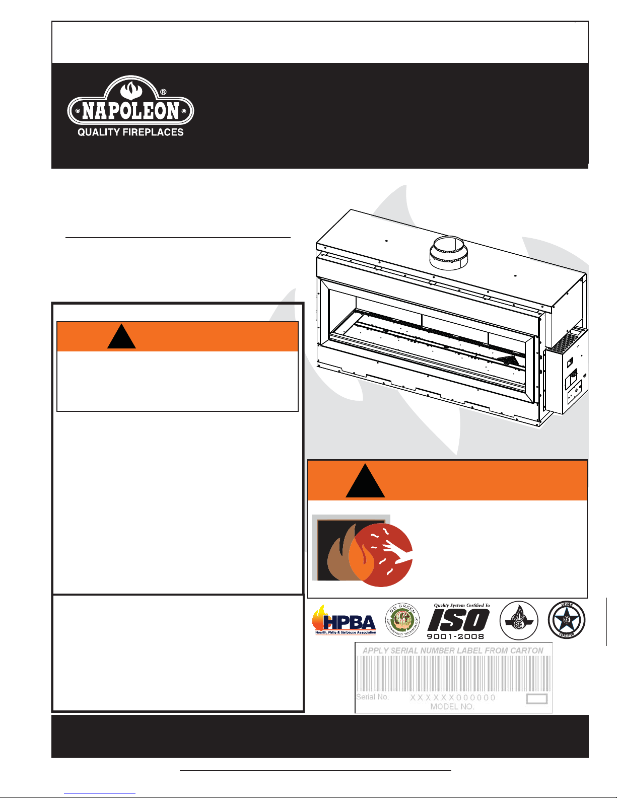
Napoleon LHD62N, LHD62P Installation And Operating Instructions Manual
INSTALLER: LEAVE THIS MANUAL WITH THE APPLIANCE.
CONSUMER: RETAIN THIS MANUAL FOR FUTURE REFERENCE.
NEVER LEAVE CHILDREN OR OTHER AT RISK INDIVIDUALS ALONE WITH THE APPLIANCE.
INSTALLATION AND
OPERATING INSTRUCTIONS
CERTIFIED UNDER CANADIAN AND AMERICAN NATIONAL STANDARDS: ANSI Z21.50 ● CSA 2.22 FOR VENTED GAS APPLIANCES.
CERTIFIED UNDER CANADIAN AND AMERICAN NATIONAL STANDARDS ANSI Z21.50 CSA 2.22 FOR VENTED GAS FIREPLACES
LHD62N
NATURAL GAS
LHD62P
PROPANE
CERTIFIED FOR CANADA AND UNITED STATES USING ANSI/CSA METHODS.
SAFETY INFORMATION
1
!
WARNING
If the information in these instructions are
not followed exactly, a fi re or explosion
may result causing property damage,
personal injury or loss of life.
- Do not store or use gasoline or other fl ammable
vapors and liquids in the vicinity of this or any
other appliance.
- WHAT TO DO IF YOU SMELL GAS:
• Do not try to light any appliance.
• Do not touch any electrical switch; do
not use any phone in your building.
• Immediately call your gas supplier from
a neighbour’s phone. Follow the gas
supplier’s instructions.
• If you cannot reach your gas supplier,
call the fi re department.
- Installation and service must be performed by a
qualifi ed installer, service agency or the supplier.
This appliance may be installed in an aftermarket,
permanently located, manufactured home (USA
only) or mobile home, where not prohibited by
local codes.
!
WARNING
HOT GLASS WILL CAUSE
BURNS.
DO NOT TOUCH GLASS UNTIL
COOLED.
NEVER ALLOW CHILDREN TO
TOUCH GLASS.
CERTIFIED
This appliance is only for use with the type of gas
indicated on the rating plate. This appliance is
not convertible for use with other gases, unless a
certifi ed kit is used.
Wolf Steel Ltd., 24 Napoleon Rd., Barrie, ON, L4M 0G8 Canada /
103 Miller Drive, Crittenden, Kentucky, USA, 41030
Phone (705)721-1212 • Fax (705)722-6031 • www.napoleonfi replaces.com • ask@napoleonproducts.com
$10.00
1.37
W415-1068 / A / 10.17.12

2
TABLE OF CONTENTS
1.0 INSTALLATION OVERVIEW 3
2.0 INTRODUCTION 4
2.1 DIMENSIONS 5
2.2 GENERAL INSTRUCTIONS 6
2.3 GENERAL INFORMATION 7
2.4 RATING PLATE / LIGHTING INSTRUCTION LOCATION 8
2.5 SHIPPING HANDLES 9
3.0 VENTING 9
3.1 VENTING LENGTHS AND COMPONENTS FOR DIRECT VENT INSTALLATIONS 10
3.2 TYPICAL VENT INSTALLATIONS 11
3.3 MINIMUM AIR TERMINAL LOCATION CLEARANCES 12
3.4 VENT APPLICATION FLOW CHART 13
3.5 DEFINITIONS 13
3.6 ELBOW VENT LENGTH VALUES 13
3.7 HORIZONTAL TERMINATION 14
3.8 VERTICAL TERMINATION 16
4.0 INSTALLATION 18
4.1 WALL AND CEILING PROTECTION 18
4.1.1 HORIZONTAL INSTALLATION 19
4.1.2 VERTICAL INSTALLATION 19
4.2 USING FLEXIBLE VENT COMPONENTS 20
4.2.1 HORIZONTAL AIR TERMINAL INSTALLATION 20
4.2.2 VERTICAL AIR TERMINAL INSTALLATION 21
4.2.3 APPLIANCE VENT CONNECTION 22
4.3 MOBILE HOME INSTALLATION 22
4.4 GAS INSTALLATION 23
5.0 FRAMING 24
5.1 MINIMUM CLEARANCE TO COMBUSTIBLE ENCLOSURES 27
5.2 INSTALLING CEMENT BOARD 29
5.3 NON-COMBUSTIBLE FINISH MATERIAL 30
5.4 MINIMUM COMBUSTIBLE MANTEL CLEARANCES 31
6.0 FINISHING 32
6.1 DOOR REMOVAL / INSTALLATION 32
6.2 TRIM INSTALLATION 33
6.3 GLASS MEDIA INSTALLATION 34
6.4 OPTIONAL ROCK PLACEMENT 34
6.5 LOGO PLACEMENT 35
7.0 ELECTRICAL CONNECTION 35
7.1 HARD WIRING CONNECTION 35
7.2 RECEPTACLE WIRING DIAGRAM 36
7.3 BATTERY HOLDER INSTALLATION 36
7.4 SCHEMATIC 37
8.0 OPERATION 38
8.1 GENERAL TRANSMITTER LAYOUT 38
8.2 INITIALIZING THE TRANSMITTER/BATTERY HOLDER FOR THE FIRST TIME 38
8.3 TEMPERATURE DISPLAY 39
8.4 FLAME HEIGHT 39
8.5 NIGHT LIGHT DIMMER CONTROL 39
8.6 CONTINUOUS PILOT / INTERMITTENT PILOT (CPI / IPI) SELECTION 40
8.7 KEY LOCK 40
8.8 LOW BATTERY / MANUAL BYPASS 40
9.0 OPERATING INSTRUCTIONS 41
10.0 ADJUSTMENT 42
10.1 RESTRICTING VERTICAL VENTS 42
10.2 PILOT BURNER ADJUSTMENT 42
10.3 VENTURI ACCESS 42
10.4 VENTURI ADJUSTMENT 43
10.5 FLAME CHARACTERISTICS 43
11.0 MAINTENANCE 44
11.1 ANNUAL MAINTENANCE 44
11.2 CONTROL ACCESS 45
11.3 MEDIA REMOVAL/REPLACEMENT 45
11.4 BURNER REMOVAL 46
11.5 BURNER ASSEMBLY REMOVAL 46
11.6 NIGHT LIGHT REPLACEMENT 47
11.7 PORCELAIN PANEL REMOVAL 47
11.8 DOOR LATCH REPLACEMENT 47
11.9 GLASS / DOOR REPLACEMENT 48
11.10 CARE OF GLASS 48
11.11 CARE OF PLATED PARTS 48
12.0 REPLACEMENTS 49
13.0 TROUBLESHOOTING 52
14.0 WARRANTY 55
NOTE: Changes, other than editorial, are denoted by a vertical line in the margin.
W415-1068 / A / 10.17.12
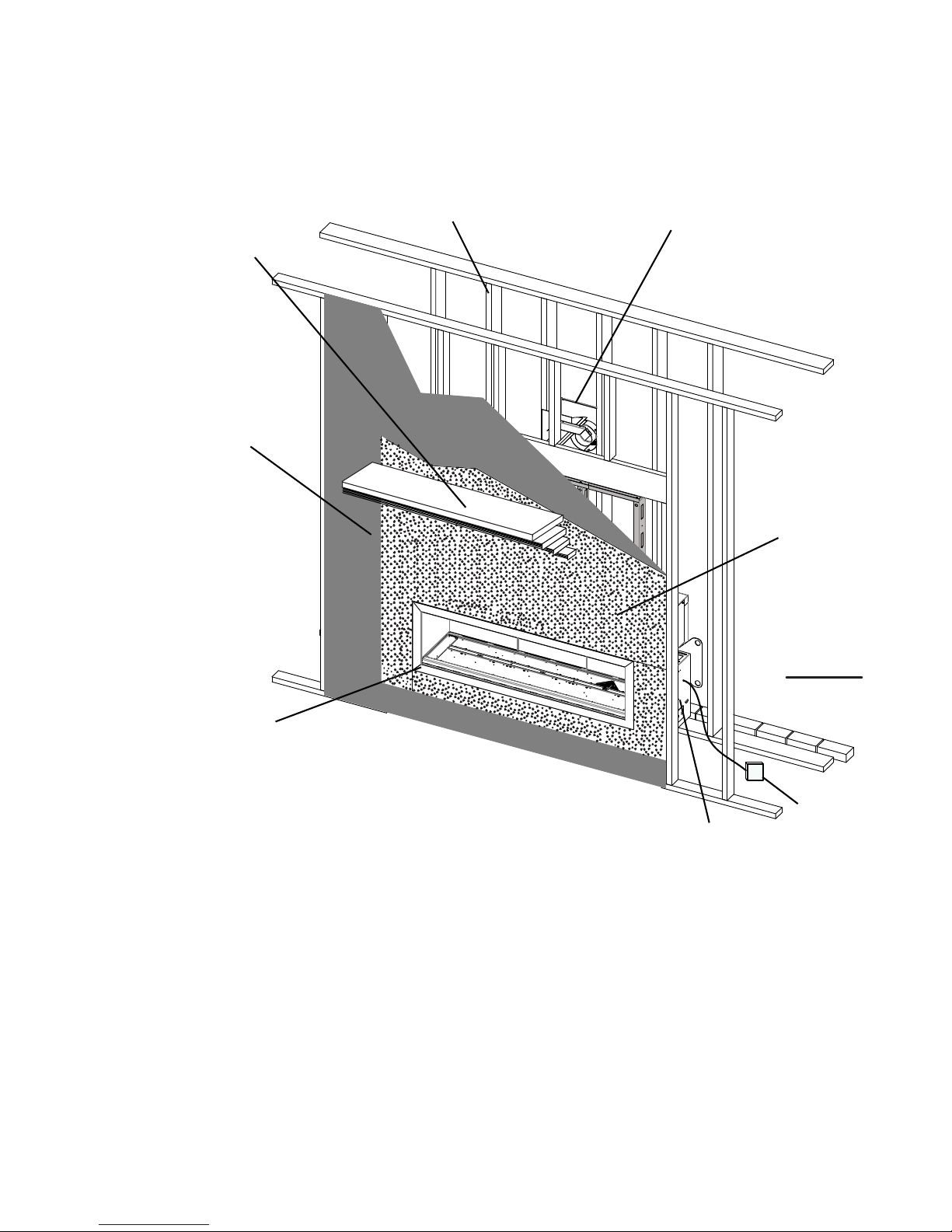
1.0 INSTALLATION OVERVIEW
3
See the section
“FRAMING MINIMUM
MANTEL
CLEARANCES”
See the section
“FRAMING MINIMUM CLEARANCE TO
COMBUSTIBLE
ENCLOSURES” for
drywall (or other
combustible
material)”
See the section
“RATING PLATE / LIGHTING
INSTRUCTION LOCATION”
See the section
“FRAMING”
See the section
“VENTING - VENTING
LENGTHS AND AIR TERMINAL
LOCATIONS”
See the section
“FRAMING MINIMUM
CLEARANCE
TO COMBUSTIBLE
ENSLOSURES”
for noncombustible
materials such
as tile, marble,
granite, etc.
Important: Extra
support may be
required
See the section
“CONTROL ACCESS”
for the control box.
See the section
“BATTERY
HOLDER
W415-1068 / A / 10.17.12
”.

4
2.0 INTRODUCTION
• THIS APPLIANCE IS HOT WHEN OPERATED AND CAN CAUSE SEVERE BURNS IF CONTACTED.
• ANY CHANGES OR ALTERATIONS TO THIS APPLIANCE OR ITS CONTROLS CAN BE DANGEROUS
AND IS PROHIBITED.
• Do not operate appliance before reading and understanding operating instructions. Failure to operate
appliance according to operating instructions could cause fi re or injury.
• Risk of fi re or asphyxiation do not operate appliance with fi xed glass removed.
• Do not connect 110 volts to the control valve.
• Risk of burns. The appliance should be turned off and cooled before servicing.
• Do not install damaged, incomplete or substitute components.
• Risk of cuts and abrasions. Wear protective gloves and safety glasses during installation. Sheet metal edges
may be sharp.
• Do not burn wood or other materials in this appliance.
• Children and adults should be alerted to the hazards of high surface temperature and should stay away to
avoid burns or clothing ignition.
• Young children should be carefully supervised when they are in the same room as the appliance. Toddlers,
young children and others may be susceptible to accidental contact burns. A physical barrier is recommended
if there are at risk individuals in the house. To restrict access to an appliance, install an adjustable safety gate
to keep toddlers, young children and other at risk individuals out of the room and away from hot surfaces.
• Clothing or other fl ammable material should not be placed on or near the appliance.
• Due to high temperatures, the appliance should be located out of traffi c and away from furniture and draperies.
• Ensure you have incorporated adequate safety measure to protect infants/toddlers from touching hot surfaces.
• Even after the appliance is out, the glass and/or screen will remain hot for an extended period of time.
• Check with your local hearth specialty dealer for safety screens and hearth guards to protect children from hot
surfaces. These screens and guards must be fastened to the fl oor.
• Any safety screen or guard removed for servicing must be replaced prior to operating the appliance.
• The appliance is a vented gas-fi red appliance. Do not burn wood or other materials in the appliance
• It is imperative that the control compartments, burners and circulating blower and its passageway in the
appliance and venting system are kept clean. The appliance and its venting system should be inspected
before use and at least annually by a qualifi ed service person. More frequent cleaning may be required due
to excessive lint from carpeting, bedding material, etc. The appliance area must be kept clear and free from
combustible materials, gasoline and other fl ammable vapors and liquids.
• Under no circumstances should this appliance be modifi ed.
• This appliance must not be connected to a chimney fl ue pipe serving a separate solid fuel burning appliance.
• Do not use this appliance if any part has been under water. Immediately call a qualifi ed service technician to
inspect the appliance and to replace any part of the control system and any gas control which has been under
water.
• Do not operate the appliance with the glass door removed, cracked or broken. Replacement of the glass
should be done by a licensed or qualifi ed service person.
• Do not strike or slam shut the appliance glass door.
• When equipped with pressure relief doors, they must be kept closed while the appliance is operating to
prevent exhaust fumes containing carbon monoxide, from entering into the home. Temperatures of the exhaust
escaping through these openings can also cause the surrounding combustible materials to overheat and catch
fi re.
• Only doors / optional fronts certifi ed with the appliance are to be installed on the appliance.
• Keep the packaging material out of reach of children and dispose of the material in a safe manner. As with all
plastic bags, these are not toys and should be kept away from children and infants.
• As with any combustion appliance, we recommend having your appliance regularly inspected and serviced as
well as having a Carbon Monoxide Detector installed in the same area to defend you and your family against
Carbon Monoxide.
• Ensure clearances to combustibles are maintained when building a mantel or shelves above the appliance.
Elevated temperatures on the wall or in the air above the appliance can cause melting, discolouration or
damage of decorations, a T.V. or other electronic components.
!
WARNING
W415-1068 / A / 10.17.12
3.2B
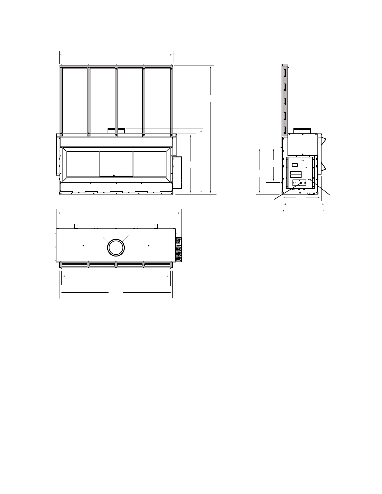
2.1 DIMENSIONS
66 1/
5
2
2
76 1/
Ø 8
73
64
66 1/
41
4
27 7/
INLET
20 3/
8
23
26 1/
26 3/
GAS
2
4
INLET
8
35 7/
ELECTRICAL
7
8
/
Ø 10
2
W415-1068 / A / 10.17.12
6
A
A
2.2 GENERAL INSTRUCTIONS
ALWAYS LIGHT THE PILOT WHETHER FOR THE FIRST TIME OR IF THE GAS SUPPLY HAS RUN OUT,
WITH THE GLASS DOOR OPENED OR REMOVED.
PROVIDE ADEQUATE CLEARANCE FOR SERVICING AND OPERATING THE APPLIANCE.
NEVER OBSTRUCT THE FRONT OPENING OF THE APPLIANCE.
OBJECTS PLACED IN FRONT OF THE APPLIANCE MUST BE KEPT A MINIMUM OF 48” FROM THE
FRONT FACE OF THE APPLIANCE.
SURFACES AROUND AND ESPECIALLY ABOVE THE APPLIANCE CAN BECOME HOT. AVOID CONTACT
WHEN THE APPLIANCE IS OPERATING.
HIGH PRESSURE WILL DAMAGE VALVE. DISCONNECT GAS SUPPLY PIPING BEFORE PRESSURE TESTING GAS
LINE AT TEST PRESSURES ABOVE 1/2 PSIG. CLOSE THE MANUAL SHUT-OFF VALVE BEFORE PRESSURE
TESTING GAS LINE AT TEST PRESSURES EQUAL TO OR LESS THAN 1/2 PSIG.
USE ONLY WOLF STEEL APPROVED OPTIONAL ACCESSORIES AND REPLACEMENT PARTS WITH THIS APPLIANCE.
USING NON-LISTED ACCESSORIES (BLOWERS, DOORS, LOUVRES, TRIMS, GAS COMPONENTS, VENTING
COMPONENTS, ETC.) COULD RESULT IN A SAFETY HAZARD AND WILL VOID THE WARRANTY AND CERTIFICATION.
!
WARNING
PROVIDE ADEQUA TE VENTILA TION.
FIRE RISK. EXPLOSION HAZARD.
THIS GAS APPLIANCE SHOULD BE INSTALLED AND SERVICED BY A QUALIFIED INSTALLER to
conform with local codes. Installation practices vary from region to region and it is important to know the
specifi cs that apply to your area, for example in Massachusetts State:
• This product must be installed by a licensed plumber or gas fi tter when installed within the commonwealth
of Massachusetts.
• The appliance damper must be removed or welded in the open position prior to installation of an appliance
insert or gas log.
• The appliance off valve must be a “T” handle gas cock.
• The fl exible connector must not be longer than 36 inches.
• A Carbon Monoxide detector is required in all rooms containing gas fi red appliances.
• The appliance is not approved for installation in a bedroom or bathroom unless the unit is a direct vent
sealed combustion product.
The installation must conform with local codes or, in
absence of local codes, the National Gas and Propane
Installation Code CSA B149.1 in Canada, or the National
Fuel Gas Code, ANSI Z223.1 / NFPA 54 in the United
States. Suitable for mobile home installation if installed in
accordance with the current standard CAN/CSA Z240MH
Series, for gas equipped mobile homes, in Canada or
NSI Z223.1 and NFPA 54 in the United States.
s long as the required clearance to combustibles is
maintained, the most desirable and benefi cial location
for an appliance is in the center of a building, thereby
allowing the most effi cient use of the heat created. The location of windows, doors and the traffi c fl ow in the
room where the appliance is to be located should be considered. If possible, you should choose a location
where the vent will pass through the house without cutting a fl oor or roof joist.
www.ncertied.org
We suggest that our gas
hearth products be installed
and serviced by professionals
who are certied in the U.S.
by the National Fireplace
®
Institute
(NFI) as NFI Gas
Specialists
If the appliance is installed directly on carpeting, vinyl tile or other combustible material other than wood
fl ooring, the appliance shall be installed on a metal or wood panel extending the full width and depth.
Some appliances have optional fans or blowers. If an optional fan or blower is installed, the junction box must
be electrically connected and grounded in accordance with local codes, use the current CSA C22.1 Canadian
Electrical Code in Canada or the ANSI/NFPA 70 National Electrical code in the United States.
W415-1068 / A / 10.17.12
4.1A
2.3 GENERAL INFORMATION
FOR YOUR SA TISFACTION, THIS APPLIANCE HAS BEEN TEST-FIRED TO ASSURE ITS OPERATION AND
QUALITY!
Altitude (FT) 0-4500 0-4500
Max. Input (BTU/HR) 50,000 50,000
Min. Input (BTU/HR) 37,000 40,000
Min. Inlet Gas Supply Pressure* 4.5 11
Max. Inlet Gas Supply Pressure* 7 13
Manifold Pressure* 3.5 10
* Measure under fl ow conditions.
When the appliance is installed at elevations above 4,500ft, and in the absence of specifi c recommendations from the
local authority having jurisdiction, the certifi ed high altitude input rating shall be reduced at the rate of 4% for each ad-
ditional 1,000ft. Expansion / contraction noises during heating up and cooling down cycles are normal and are to
be expected. Change in fl ame appearance from “HI” to “LO” is more evident in natural gas than in propane.
7
LHD62
NG LP
This appliance is approved for bathroom, bedroom and bed-sitting room installations and is certifi ed for mobile
home installation.
This appliance is only for use with the type of gas indicated on the rating plate. This appliance is not
convertible for use with other gases, unless a certifi ed kit is used.
There are two switches that control the function of the appliance. One on the receiver that must be placed in
the middle position. The other is on the control module that must be in the “I” position, which denotes on. If
these switches aren’t in these locations the appliance will not work, see “REMOTE RECEIVER INSTALLATION” and “CONTROL MODULE” section.
NOTE: The protective wrap on plated parts is best removed when the assembly is at room temperature
but this can be improved if the assembly is warmed, using a hair dryer or similar heat source.
This appliance is equipped with a remote control system, which requires batteries (supplied) to be installed.
The transmitter takes 3 “AAA” batteries and in the case of a power failure the receiver takes 4 “AA” batteries.
W415-1068 / A / 10.17.12
8
2.4 RATING PLATE / LIGHTING INSTRUCTION LOCATION
!
WARNING
ALLOW THE APPLIANCE TO COOL BEFORE PERFORMING ANY MAINTENANCE OR CLEANING.
Both the rating plate and lighting instructions are attached to a cable and inserted in the slot on the lower left
side of the appliance. It is recommended to remove the door prior to instruction removal. Using your fi ngers or
a tool such as a screw driver or pencil, gently pull both cables toward you. With the cable at the bulb end of the
slot, wiggle the rating plate out being careful not to tear the instructions as they pass through the slot.
To replace, slide the instructions and the chain back through the slot and re-attach the door (if removed).
NOTE: The rating plate must remain with the appliance at all times. It must not be removed.
&(57,),('81'(5+202/2*8(6(/21/(61250(6$16,=E&6$E9(17('*$6),5(3/$&()2<(5$8*$=9(17,/e
VENTED GAS FIREPLACE. APPROVED FOR BEDROOM, BATHROOM AND BED-SITTING ROOM INSTALLATION. SUITABLE FOR MOBILE HOME INSTALLATION IF INSTALLED IN ACCORDANCE WITH THE CURRENT
STANDARD CAN/CSA Z240MH SERIES GAS EQUIPPED MOBILE HOMES, IN CANADA OR IN THE UNITED STATES THE MANUFACTURED HOME CONSTRUCTION AND SAFETY STANDARD, TITLE 24 CFR, PART
CERTIFIED
CERTIFIED FOR / CERTIFIEE
POUR CANADA / USA
REFERENCE # 161746
NOT FOR USE WITH
62/,')8(/)2586(
WITH GLASS DOORS
CERTIFIED WITH THIS
81,721/<
WARNING: '2127$''$1<0$7(5,$/
TO THE APPLIANCE, WHICH WILL COME IN
CONTACT WITH TEH FLAMES, OTEHR THAN
7+$76833/,('%<7+(0$18)$&785(5
:,7+7+($33/,$1&(
MINIMUM CLEARANCE TO
COMBUSTIBLE MATERIALS:
TOP 0”
FLOOR 0”
RECESSED DEPTH 26”
SIDES 0”
BACK 0”
9(17723 µ
9(176,'(6%27720 µ
9(57,&$/9(17 µ
MANTEL 12”*
7236,'(6%$&.3(567$1'2))63$&(56)25)5$0,1*0$7(5,$/6)25),1,6+,1*0$7(5,$/6
SEE OWNER’S MANUAL
0$;,080+25,=217$/(;7(16,21/·(;7(16,21+25,=217$/(0$;,0$/(µ6((,16758&7,21
0$18$/)25*5($7(5(;7(16,216
6((2:1(5·6,16758&7,210$18$/)250,1,080$1'0$;,080/(1*7+6
(/(&75,&$/5$7,1*9+=/(667+$1$03(5(6
WOLF STEEL LTD.
24 NAPOLEON ROAD, BARRIE, ON, L4M 0G8 CANADA
3280. WHEN THIS US STANDARD IS NOT APPLICABLE USE THE STANDARD FOR FIRE SAFETY CRITERIA FOR MANUFACTURED HOME INSTALLATIONS, SITES AND COMMUNITIES, ANSI/NFPA 501A. FOYER DE
CHAFFAGE AU GAZ AVEC ÉVACUATION. HOMOLOGUÉ POUR INSTALLATION DANS UNE CHAMBRE À COUCHER, UNE SALLE DE BAIN ET UN STUDIO. APPROPRIÉ POUR INSTALLATION DANS UNE MAISON
MOBILE SI SON INSTALLATION CONFORME AUX EXIGENCES DE LA NORME CAN/CSA Z240MH SÉRIE DE MAISONS MOBILES ÉQUIPÉES AU GAZ EN VIGEUR AU CANADA OU AUX ÉTATS-UNIS DE LA NORME DE
SECURITE ET DE CONSTRUCTION DE MAISONS MANUFACTUREE, TITRE 24 CFR, SECTION 3280. DANS LE CAS OU CETTE NORME D’ÉTATS-UNIS NE PEUT ETRE APPLIQUÉE, SE REFERER A LA NORME
RELATIVE AU CRITÈRE DE MESURES DE SÉCURITÉ CONTRE L’INCENDIE POUR LES INSTALLATIONS DANS LES MAISONS MANUFACTURÉS, LES SITES ET LES COMMUNAUTÉS, ANSI/NFPA 501A. THIS
APPLIANCE MUST BE INSTALLED IN ACCORDANCE WITH LOCAL CODES, IF ANY; IF NONE, FOLLOW THE CURRENT ANSI Z223.1 OR CSA B149, INSTALLATION CODES. INSTALLER L’APPAREIL SELON LES
CODES D’INSTALLATION ANSI Z223.1 OU CSA-B149 EN VIGUER.
MODEL NATURAL GAS /
0-4500FT (0-1370M) $/7,78'(e/e9$7,21 0-4500FT (0-1370M)
50,000 BTU/H
%78+ 5('8&(',1387$/,0(17$7,215e'8,7( ,000 BTU/H
µ:$7(5&2/801'·81(&2/211('·($8
PRESSION AU COLLECTEUR
´:$7(5&2/801'·81(&2/211('·($8 0,1,0806833/<35(6685( 11” WATER COLUMN/D’UNE COLONNE D’EAU
´:$7(5&2/801'·81(&2/211('·($8 0$;,0806833/<35(6685( 13” WATER COLUMN/D’UNE COLONNE D’EAU
3)(
7+($33/,$1&(0687%(9(17('86,1*7+($335235,$7(
1$32/(219(17.,766((2:1(56,167$//$7,210$18$/
5(6($/,1*,61(&(66$5<$)7(56(59,&,1*7+(9(17$,5
GAZ NATURAL
LHD62N LHD62P
)259(17,1*63(&,),&63523(55(,167$//$7,21$1'
CLHD62N CLHD62P
INPUT / ALIMENTATION 50,000 BTU/H
MANIFOLD PRESSURE / 10” WATER COLUMN/D’UNE COLONNE D’EAU
PRESSION D’ALIMENTATION MINIMALE
PRESSION D’ALIMENTATION MAXIMALE
,17$.(6<67(0
/·$33$5(,/'2,7e9$&8(56(6*$=(187,/,6$17
/·(16(0%/('·e9$&8$7,2135235($1$32/(215e)e5(5
$80$18(/'·,167$//$7,21'(35235,e7$,5(3285
/·(9$&8$7,2135(&,6(,/(67,03257$17'(%,(1
5e,167$//(5(75(6&(//(5/·(9(17$35e6$92,5$6685e
/(0$,17,(1'86<67e0('(35,6('·$,5
'(6686&Ñ7e6$55,Ë5(6(/21/(6(63$&(856'(
'e*$*(0(173285/(60$7(5,$8;'·266$785(6(/21
/$0$18(/'(35235,e7$,5(3285/(60$7e5,$8;'(
),1,7,21/·(;7(16,21+25,=217$/(0$;,0$/(µ
5e)e5(5$80$18$/'·,16758&7,213285'(6
(;7(16,2163/86*5$1'(65e)e5(5$80$18(/
'·,167$//$7,21'(35235,e7$,5(
SERIAL NUMBER/ NO. DE SÉRIE: LHD62
MODEL PROPANE /
3523$1(02'Ë/(
63e&,),&$7,216e/(&75,48(69
+=02,16'($03Ë5(6
UN COMBUSTIBLE SOLIDE NE
3$6È75e87,/,6e$9(&&(7
$33$5(,/87,/,6(5$9(&/(6
3257(9,75e(6
+202/2*8e(66(8/(0(17
$9(&&(77(81,7e
$'9(57,66(0(17N’AJOUTEZ PAS
$&(7$33$5(,/$8&810$7e5,$8'(9$17
(175(5(1&217$&7$9(&/(6)/$00(6
$875(48(&(/8,48,(67)2851,$9(&7
&(7$33$5(,/3$5/()$%5,&$17
'e*$*(0(1760,1,0$8;'(60$7e5,$8;
COMBUSTIBLES :
DESSUS 0”
PLANCHER 0”
352)21'(85'(/·(1&/$9()$&(µ
&Ñ7e6 µ
$55,Ë5( µ
'(6686'8&21'8,7'·(9(17 µ
&Ñ7e6(7'(66286'8&21'8,7
'·(9(17 µ
&21'8,7'·(9(179(57,&$/ µ
TABLETTE 12”*
W385-1864
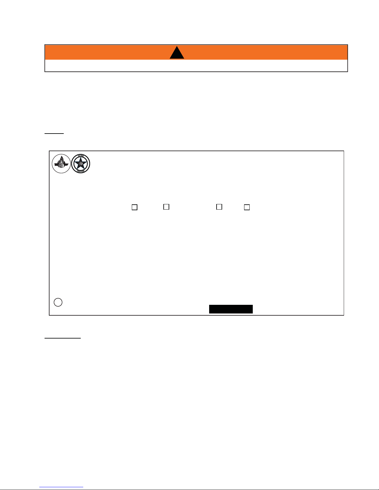
INSTALLER: It is your responsibility to check off the appropriate box on the rating plate according to
the model, venting and gas type of the appliance.
This illustration is for reference only. Refer to the rating plate on the appliance for accurate information.
W415-1068 / A / 10.17.12
2.5 SHIPPING HANDLES
IMPORTANT
This appliance fully dressed weighs 575lbs.
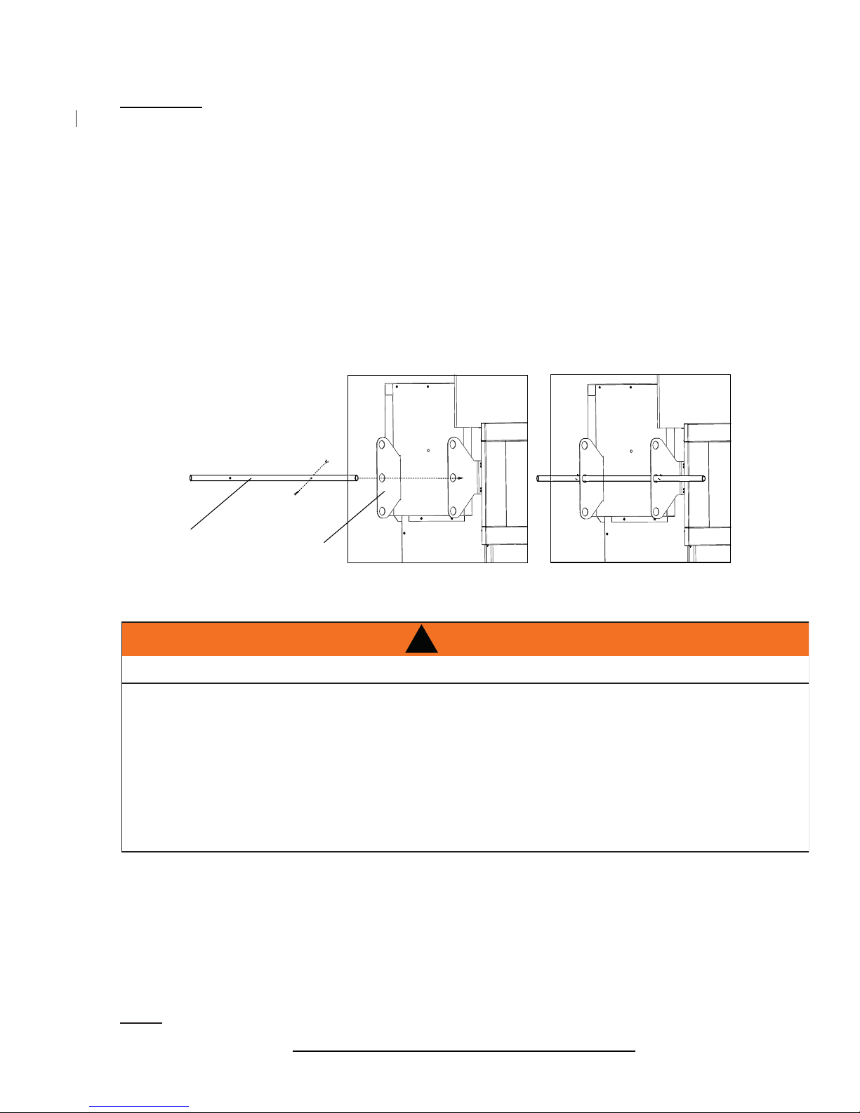
Shipping brackets were shipped secured to the appliance. The unit can be lifted by inserting the shipping
handle through a set of holes. Shipping brackets must eventually be removed if framing to minimum enclosure
dimensions.
When preparing to lift the appliance follow the directions and illustrations provided.
1. Locate the shipping handles provided with the bolts and wing nuts already attached.
2. Remove the bolt and wing nut from one end of the shipping handle and insert it into the appropriate set
of holes on the shipping bracket, most comfortable for lifting the appliance, as shown below.
3. Once the shipping handle is through the holes, reattach the bolt and wing nut to the handle, ensuring
they are secured on the outer sides of the shipping brackets, as shown below.
4. Repeat these steps to secure the second shipping handle on the opposite side of the appliance.
5. In all applications, the shipping handles must be removed once the appliance is located in it’s
fi nal position.
9
SHIPPING
HANDLE
3.0 VENTING
RISK OF FIRE, MAINTAIN SPECIFIED AIR SPACE CLEARANCES TO VENT PIPE AND APPLIANCE.
IF VENTING IS INCLUDED WITH SPACERS THE VENT SYSTEM MUST BE SUPPORTED EVERY 3 FEET
FOR BOTH VERTICAL AND HORIZONTAL RUNS. USE SUPPORTS OR EQUIVALENT
NON-COMBUSTIBLE STRAPPING TO MAINTAIN THE REQUIRED CLEARANCE FROM
COMBUSTIBLES. USE WOLF STEEL LTD. SUPPORT RING ASSEMBLY W010-0370 OR EQUIVALENT
NON-COMBUSTIBLE STRAPPING TO MAINTAIN THE MINIMUM CLEARANCE TO COMBUSTIBLES
FOR BOTH VERTICAL AND HORIZONTAL RUNS. SPACERS ARE ATTACHED TO THE INNER PIPE AT
PREDETERMINED INTERVALS TO MAINTAIN AN EVEN AIR GAP TO THE OUTER PIPE. THIS GAP IS
REQUIRED FOR SAFE OPERATION. A SPACER IS REQUIRED AT THE START, MIDDLE AND END OF
EACH ELBOW TO ENSURE THIS GAP IS MAINTAINED. THESE SPACERS MUST NOT BE REMOVED.
For safe and proper operation of the fi replace follow the venting instruction exactly. Deviation from the minimum
vertical vent length can create diffi culty in burner start-up and/or carboning. Under extreme vent confi gurations,
allow several minutes (5-15) for the fl ame to stabilize after ignition. Provide a means for visually checking the vent
connection to the fi replace after the fi replace is installed. Use a fi restop, vent pipe shield or attic insulation shield
when penetrating interior walls, fl oor or ceiling.
SHIPPING
BRACKETS
!
WARNING
This fi replaces uses 8” exhaust / 10” air intake vent pipe system.
Refer to the section applicable to your installation.
NOTE: If for any reason the vent air intake system is disassembled; reinstall per the instructions provided
for the initial installation.
7.3A
W415-1068 / A / 10.17.12

10
3.1 VENTING LENGTHS AND COMPONENTS FOR DIRECT VENT INSTALLATIONS
For vent systems that provide seals on the inner exhaust fl ue, only the outer air intake joints must be sealed
using a red high temperature silicone (RTV). This same sealant may be used on both the inner exhaust and
outer intake vent pipe joints of all other approved vent systems except for the exhaust vent pipe connection to the
fi replace fl ue collar which must be sealed using the black high temperature sealant Mill Pac.
When using Wolf Steel venting components, use only approved Wolf Steel fl exible components with the
following termination kits: wall terminal kit GD622R, or 1/12 to 7/12 pitch roof terminal kit GD610, 8/12 to 12/12
roof terminal kit GD611 or fl at roof terminal kit GD612. With fl exible venting, in conjunction with the various
terminations, use either the 5 foot vent kit GD620 or the 10 foot vent kit GD630.
For optimum fl ame appearance and fi replace performance, keep the vent length and number of elbows to
a minimum.
The air terminal must remain unobstructed at all times. Examine the air terminal at least once a year to
verify that it is unobstructed and undamaged.
The minimum allowable vertical vent length is 3 feet maximum allowable vertical vent length is 40 feet. The
maximum number of allowable 8” vent connections is three horizontally or vertically (excluding the fi replace and
the air terminal connections).
When venting, the horizontal run must be kept to a minimum of 36“ or a maximum of 20 feet. If a 20 foot
horizontal run is required, the fi replace must have a minimum vertical rise immediately off the fi replace of 57”.
When terminating vertically, the vertical rise is a minimum 36“ and a maximum 40 feet above the fi replace.
For optimum performance, it is recommended that all horizontal runs have a minimum 1/4” rise per foot.
Provide a means for visually checking the vent connection to the fi replace after the fi replace is installed.
Do not allow the inside liner to bunch up on horizontal or vertical runs and elbows. Keep it pulled tight.
A 3/4” air gap between the inner and outer liner all around is required for safe operation. Use a fi restop
when penetrating interior walls, fl oor or ceiling.
8.4
W415-1068 / A / 10.17.12
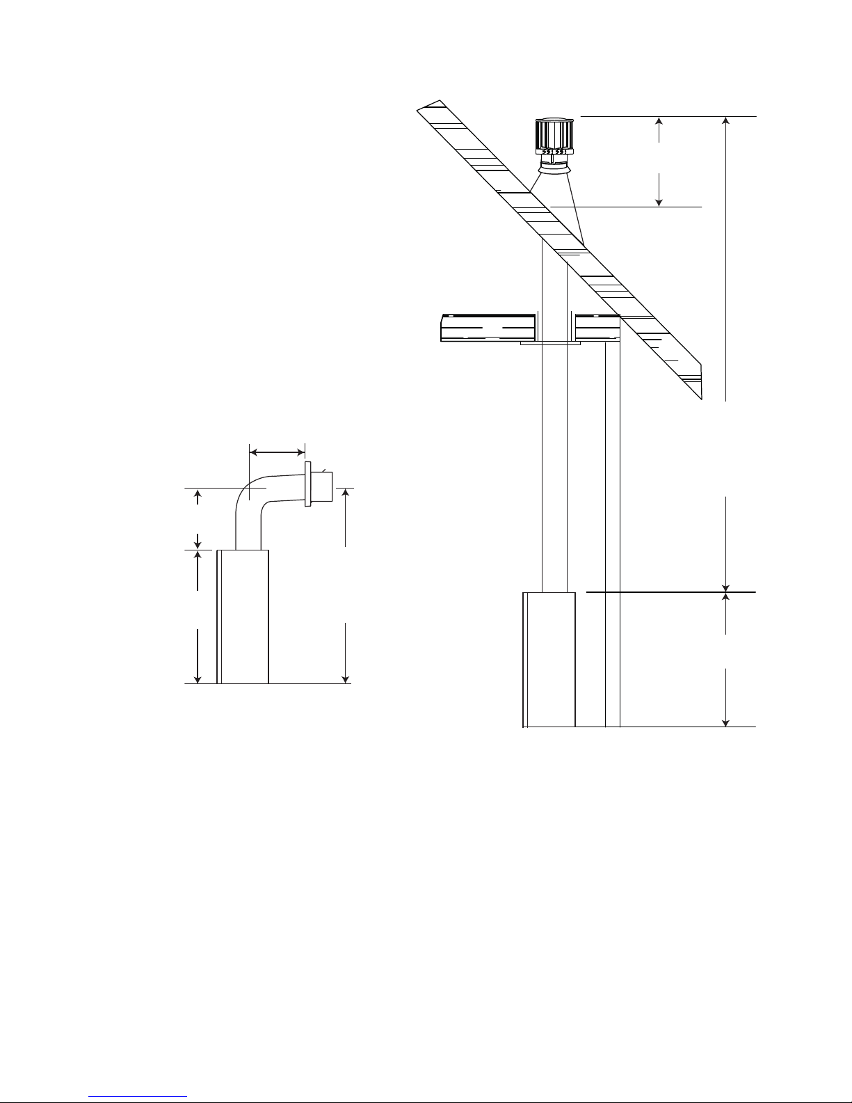
3.2 TYPICAL VENT INSTALLATIONS
11
16” MINIMUM
20”
MAXIMUM
48” MINIMUM
36”
* See “VENTING” section.
40 FEET
MAXIMUM
3 FEET
MINIMUM
84”
MINIMUM
PLUS
RISE*
36”
W415-1068 / A / 10.17.12
12
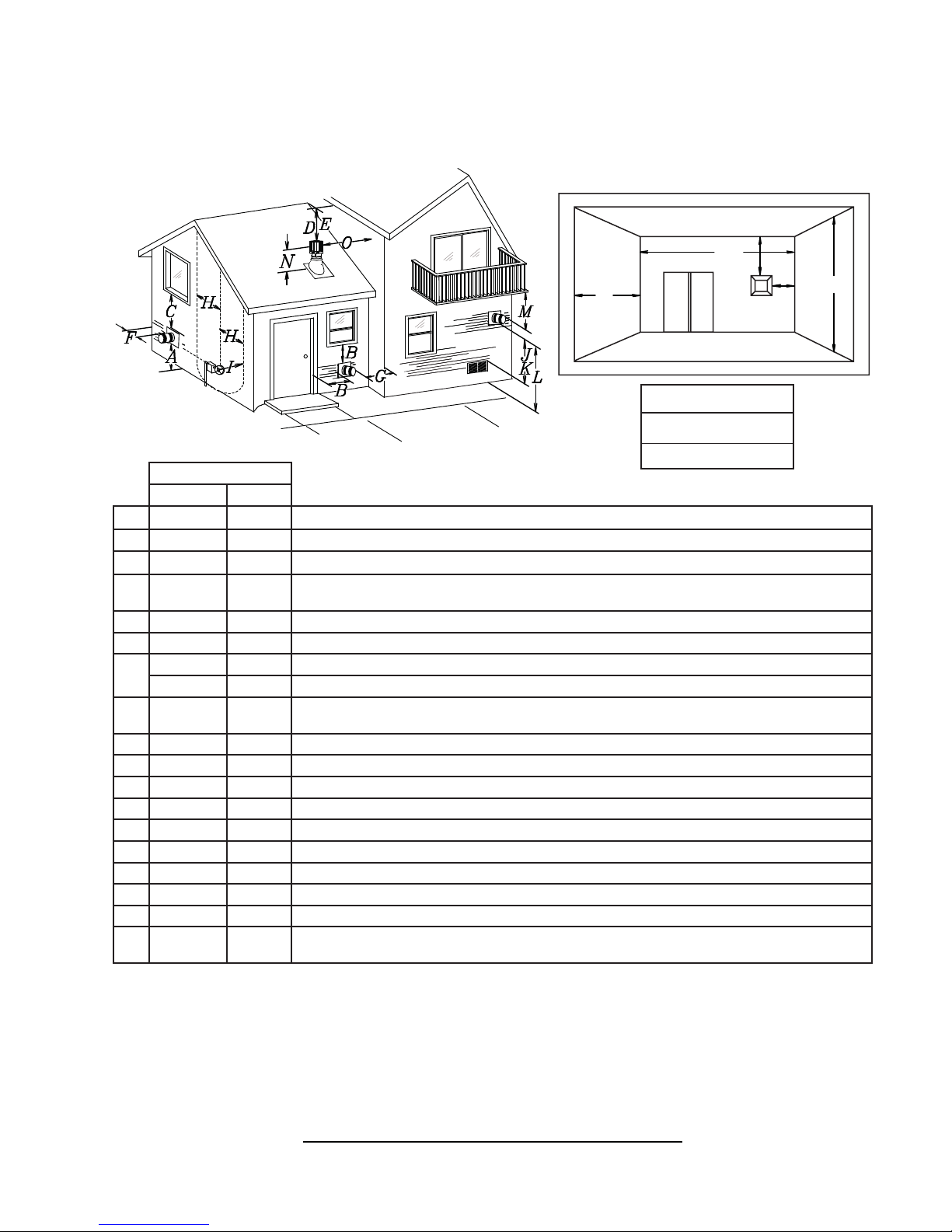
3.3 MINIMUM AIR TERMINAL LOCATION CLEARANCES
COVERED BALCONY APPLICATIONS
R
Q
M
G
P
Q
R
R
MIN
MAX
MAX
= 3 feet
= 2 x
Q
feet
ACTUAL
INSTALLATIONS
CANADA U.S.A.
A 12” 12” Clearance above grade, veranda porch, deck or balcony.
B 12”
Δ
9”
Δ
Clearance to windows or doors that open.
C 12” * 12” * Clearance to permanently closed windows.
D 18” ** 18” **
Vertical clearance to ventilated soffi ts located above the terminal within a horizontal distance of 2’ from
the centerline of the terminal.
E 12” ** 12” ** Clearance to unventilated soffi t.
F 0” 0” Clearance to an outside corner wall.
0” *** 0” *** Clearance to an inside non-combustible corner wall or protruding non-combustible obstructions (chimney, etc.).
G
2” *** 2” *** Clearance to an inside combustible corner wall or protruding combustible obstructions (vent chase, etc.).
H 3’ 3’ ****
Clearance to each side of the centerline extended above the meter / regulator assembly to a maximum
vertical distance of 15’.
I 3’ 3’ **** Clearance to a service regulator vent outlet.
J 12” 9” Clearance to a non-mechanical air supply inlet to the building or a combustion air inlet to any other appliance.
K 6’ 3’ Clearance to a mechanical air supply inlet.
L 7’ ‡ 7’ **** Clearance above a paved sidewalk or paved driveway located on public property.
M 12” †† 12” **** Clearance under a veranda, porch, deck or balcony.
N 16” 16” Clearance above the roof.
O 2’ †* 2’ †* Clearance from an adjacent wall including neighbouring buildings.
P 8’ 8’ Roof must be non-combustible without openings.
Q 3’ 3’ See chart for wider wall dimensions.
R 6’ 6’
The terminal shall not be located less than 6 feet under a window that opens on a horizontal plane in a structure with three walls and a roof.
Δ
* Recommended to prevent condensation on windows and thermal breakage
** It is recommended to maximize the distance to vinyl clad soffi ts.
*** The periscope requires a minimum 18” clearance from an inside corner.
**** This is a recommended distance. For additional requirements check local codes.
† 3 feet above if within 10 feet horizontally.
‡ A vent shall not terminate where it may cause hazardous frost or ice accumulations on adjacent property surfaces.
†† Permitted only if the veranda, porch, or deck is fully open on a minimum of two sides beneath the fl oor.
†* Recommended to prevent recirculation of exhaust products. For additional requirements check local codes.
See chart for deeper wall dimensions. The terminal shall not be installed on any wall that has an opening between the terminal and the open side of the structure.
12.3B
W415-1068 / A / 10.17.12
3.4 VENT APPLICATION FLOW CHART
13
TOP EXIT
Horizontal Termination
Vertical rise is equal
to or greater than
the horizontal run
Horizontal run +
vertical rise to
maximum of 40 feet
3.5 DEFINITIONS
For the following symbols used in the venting calculations and examples are:
> - greater than
> - equal to or greater than
< - less than
< - equal to or less than
HT - total of both horizontal vent lengths (Hr) and offsets (Ho) in feet
HR - combined horizontal vent lengths in feet
HO - offset factor: .03 (total degrees of offset - 90°*) in feet
VT - combined vertical vent lengths in feet
Vertical rise is less
than horizontal run
Horizontal run +
vertical rise to
maximum of 24.75
feet
4.2 times the
vertical rise equal to
or greater than the
horizontal run
Vertical Termination
Vertical rise is equal
to or greater than
the horizontal run
Horizontal run +
vertical rise to
maximum of 40 feet
Vertical rise is less
than horizontal run
Horizontal run +
vertical rise to
maximum of 40 feet
3 times the vertical
rise equal to or
greater than the
horizontal run
13.1
14.1
3.6 ELBOW VENT LENGTH VALUES
FEET INCHES
1° 0.03 0.5
15° 0.45 6.0
30° 0.9 11.0
45° 1.35 16.0
90°* 2.7 32.0
* The fi rst 90° offset has a zero value and is shown in the formula as - 90°
15.1
W415-1068 / A / 10.17.12
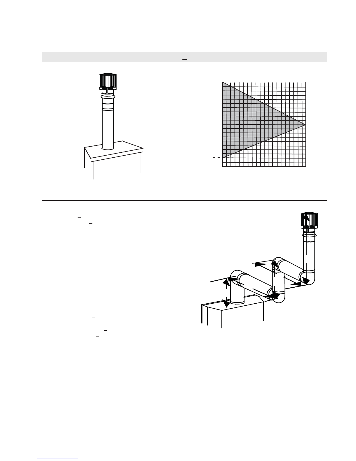
14
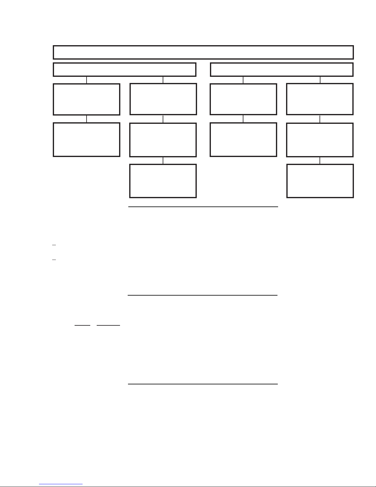
3.7 HORIZONTAL TERMINATION
(HT) < (VT)
Simple venting confi guration (only one 90° elbow)
See graph to determine the required vertical
rise VT for the required horizontal run HT.
40
39
30
REQUIRED
VERTICAL
20
RISE IN
FEET VT
10
4
0
2.5 5 7.5 10 12.5 15
HORIZONTAL VENT RUN PLUS OFFSET IN
FEET HT
The shaded area within the lines represents
acceptable values for HT and V
For vent confi gurations requiring more than one 90° elbow, the following formulas apply:
Formula 1: HT < V
T
Formula 2: HT + VT < 40 feet
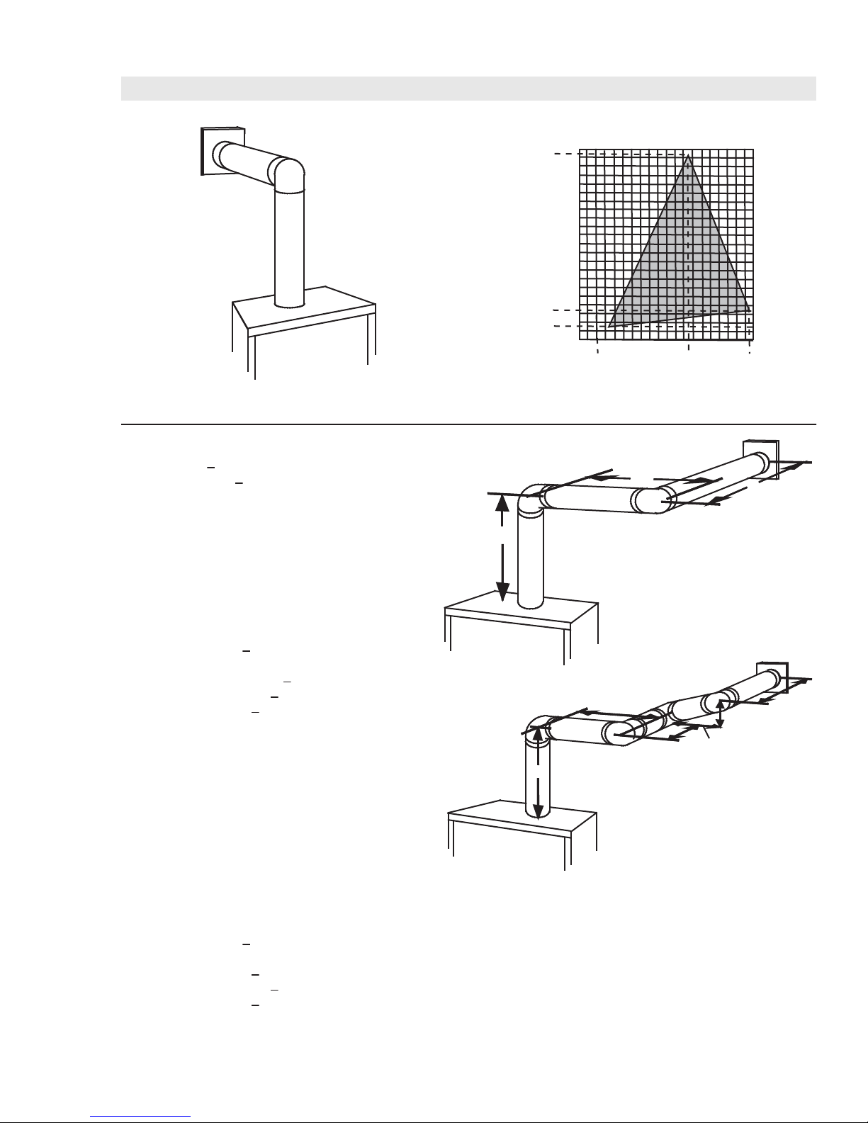
Example:
V1 = 3 FT
90°
V2 = 8 FT
VT = V1 + V2= 3 FT + 8 FT = 11 FT
V
H1 = 2.5 FT
2
H2 = 2 FT
HR = H1 + H2 = 2.5 + 2 = 4.5 FT
HO = .03 (three 90° elbows - 90°) = .03 (270° - 90°) = 5.4 FT
HT = HR + HO = 4.5 + 5.4 = 9.9 FT
HT + VT = 9.9 + 11 = 20.9 FT
90°
90°
H
1
17.5 20
T
H
2
Formula 1: HT < V
T
9.9 < 11
Formula 2: HT + VT < 40 FT
20.9 < 40
Since both formulas are met, this vent confi guration is acceptable.
W415-1068 / A / 10.17.12
V
1
15
V
V
V
V
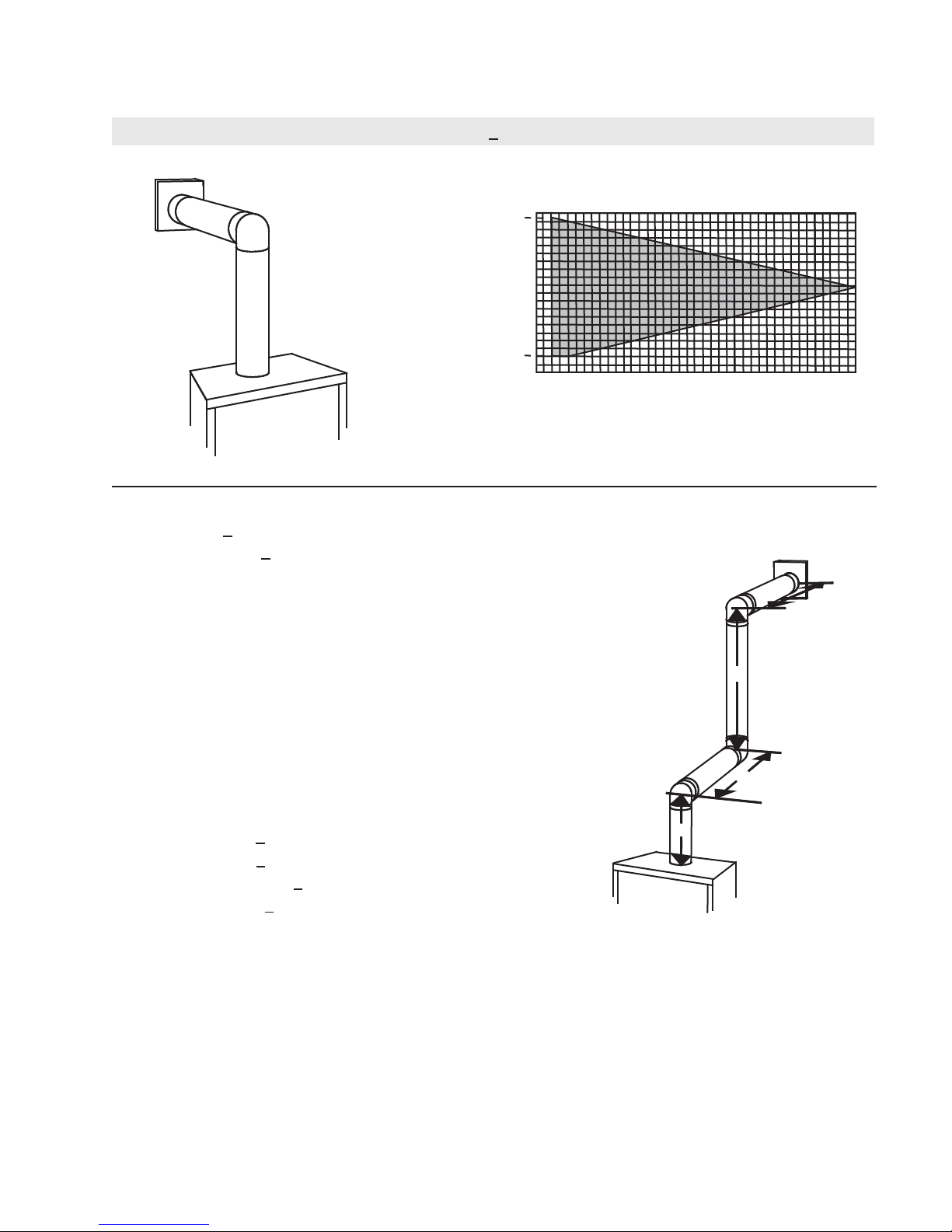
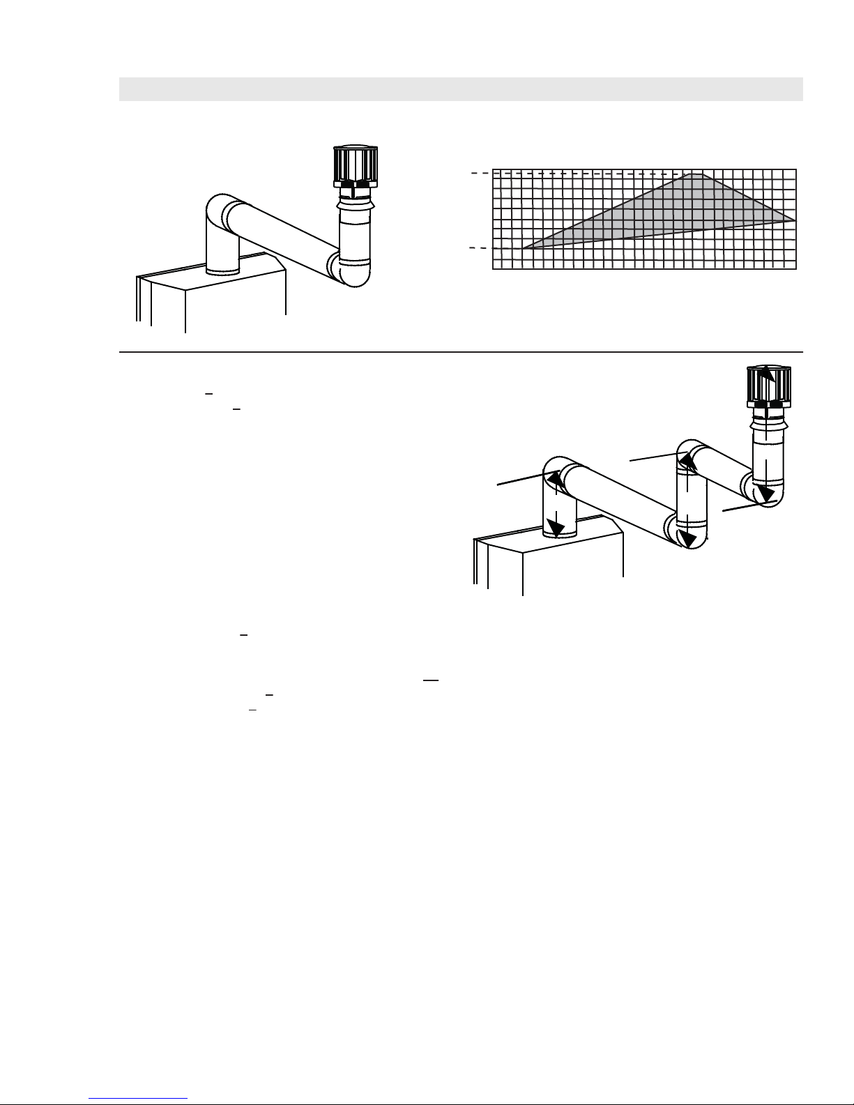
(HT) > (VT)
Simple venting configuration (only one 90° elbow)
See graph to determine the required vertical rise VT for the
required horizontal run H
150
147”
.
T
REQUIRED
VERTICAL
100
RISE IN
INCHES V
T
57”
50
48”
40
0
515
2’
10
12.5’
20
19.5’
HORIZONTAL VENT RUN PLUS OFFSET IN FEET H
T
The shaded area within the lines represents acceptable
values for HT and VT
For vent configurations requiring more than one 90° elbow, the following formulas apply:
< 4.2 V
Formula 1:
Formula 2: HT + V
H
T
T
< 24.75 feet
T
90°
H
1
H
2
Example:
= VT = 6 FT
1
H
= 3 FT
1
H
= 5 FT
2
H
= H
+ H
R
H
= .03 (two 90° elbows - 90°) = .03 (180° - 90°) = 2.7 FT
O
H
= H
T
H
+ V
T
= 3 + 5 = 8 FT
1
2
+ H
= 8 + 2.7 = 10.7 FT
R
O
= 10.7 + 6 = 16.7 FT
T
V
1
90°
Formula 1: HT < 4.2 V
4.2 VT = 4.2 x 6 = 25.2 FT
10.7 < 25.2
Formula 2: HT + V
16.7 < 24.75
Since both formulas are met, this vent configuration is acceptable.
Example:
= 4 FT
1
= 1.5 FT
2
= V
+ V
T
H
= 2 FT
1
H
= 1 FT
2
H
= 1 FT
3
H
= 1.5 FT
4
H
= H
R
H
= .03 (four 90° elbows - 90°) = .03 (360° - 90°) = 8.1 FT
O
H
= H
T
H
+ V
T
= 4 + 1.5 = 5.5 FT
1
2
+ H2 + H
1
+ H
R
= 13.6 + 5.5 = 19.1 FT
T
+ H4 = 2 + 1 + 1 + 1.5 = 5.5 FT
3
= 5.5 + 8.1 = 13.6 FT
O
Formula 1: HT < 4.2 V
4.2 VT = 4.2 x 5.5 = 23.1 FT
T
< 24.75 FT
T
T
90°
90°
90°
H
1
90°
V
1
V
H
H
2
3
H
4
2
13.6 < 23.1
Formula 2: HT + V
19.1 < 24.75
< 24.75 FT
T
Since both formulas are met, this vent configuration is acceptable.
W415-1068 / A / 10.17.12
16
3.8 VERTICAL TERMINATION
(HT) < (VT)
Simple venting configurations.
See graph to determine the required vertical rise V
required horizontal run H
40
30
REQUIRED
VERTICAL
20
RISE IN
FEET V
T
10
4
0
5101520
HORIZONTAL VENT RUN PLUS OFFSET IN FEET H
The shaded area within the lines represents acceptable
values for H
For vent configurations requiring one or more 90° elbows the following formulas apply:
Formula 1: H
Formula 2: HT + V
< V
T
T
< 40 feet
T
and VT
T
for the
.
T
T
T
Example:
V
= 5 FT
1
V
= 6 FT
2
V
= 10 FT
3
V
= V
+ V2 + V3 = 5 + 6 + 10 = 21 FT
T
1
H
= 8 FT
1
H
= 2.5 FT
2
H
= H
+ H
R
H
= .03 (four 90° elbows - 90°)
O
= .03 (360° - 90°) = 8.1 FT
H
= H
T
H
+ V
T
Formula 1: H
18.6 < 21
Formula 2: HT + V
39.6 < 40
= 8 + 2.5 = 10.5 FT
1
2
+ H
= 10.5 + 8.1 = 18.6 FT
R
O
= 18.6 + 21 = 39.6 FT
T
< V
T
T
< 40 FT
T
Since both formulas are met, this vent configuration is acceptable.
90°
V
3
90°
H
2
V
H
1
V
1
2
90°
90°
W415-1068 / A / 10.17.12
17
(HT) > (VT)
Simple venting configurations.
See graph to determine the required vertical rise V
required horizontal run H
20
19
REQUIRED
VERTICAL
RISE IN
FEET V
10
T
4
0
5101520
HORIZONTAL VENT RUN PLUS OFFSET IN FEET H
The shaded area within the lines represents acceptable
values for HT and VT
For vent configurations requiring more than two 90° elbows the following formulas apply:
Formula 1: H
Formula 2: HT + V
< 3V
T
T
< 40 feet
T
Example:
V
= 2 FT
1
V
= 1 FT
2
V
= 1.5 FT
3
V
= V
+ V2 + V3 = 2 + 1 + 1.5 = 4.5 FT
T
1
H
= 6 FT
1
H
= 2 FT
2
H
= H
+ H
R
H
= .03 (four 90° elbows - 90°)
O
= .03 (360° - 90°) = 8.1 FT
H
= H
T
H
+ V
T
= 6 + 2 = 8 FT
1
2
+ H
= 8 + 8.1 = 16.1 FT
R
O
= 16.1 + 4.5 = 20.6 FT
T
90°
H
V
1
1
90°
for the
.
T
H
V
2
T
25 30
V
2
T
3
90°
90°
Formula 1: HT < 3V
3VT = 3 x 4.5 = 13.5 FT
T
16.1 > 13.5
Since this formula is not met, this vent configuration is unacceptable.
Formula 2: HT + VT < 40 feet
20.6 < 40
Since only formula 2 is met, this vent configuration is unacceptable and a new appliance location or vent configuration will
need to be established to satisfy both formulas.
W415-1068 / A / 10.17.12
 Loading...