

Napoleon LHD50N, LHD50N2, LHD50P, LHD50P2, LHD50PLHD50P2 Installation And Operating Instructions Manual
INSTALLER: LEAVE THIS MANUAL WITH THE APPLIANCE
other
,
APPOSEZ LÉI
CONSUMER: RETAIN THIS MANUAL FOR FUTURE REFERENCE
INSTALLATION AND
OPERATING INSTRUCTIONS
CERTIFIED UNDER CANADIAN AND AMERICAN NATIONAL STANDARDS: ANSI Z21.50 ● CSA 2.22 FOR VENTED GAS FIREPLACES.
LHD50N
LHD50N2
NATURAL GAS
1
LHD50P
LHD50P2
PROPANE
CERTIFIED FOR CANADA AND UNITED STATES USING ANSI/CSA METHODS.
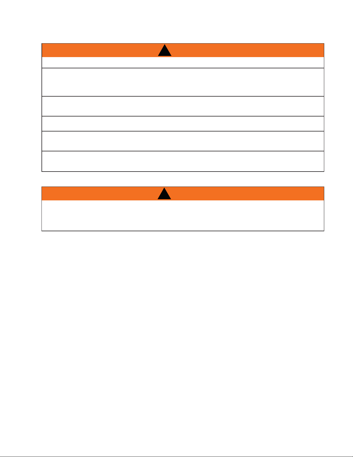
SAFETY INFORMATION
!
WARNING
If the information in these instructions are not
followed exactly, a fire or explosion may result
causing property damage, personal injury or
loss of life.
- Do not store or use gasoline or other flammable
vapors and liquids in the vicinity of this or any other
appliance.
-
WHAT TO DO IF YOU SMELL GAS:
- Do not try to light any appliance
- Do not touch any electrical switch; do
not use any phone in your building.
- Immediately call your gas supplier from
a neighbor's phone. Follow the gas
supplier’s instructions.
- If you cannot reach your gas supplier,
call the fire department.
- Installation and service must be performed by a
qualified installer, service agency or the supplier.
a
LHD50N ILLUSTRATED
CERTIFIED
APPOSEZ L’ÉTIQUETTE DU NUMÉRO DE SÉRIE DU CARTON
PPOSEZ L’ÉTI
N° de série
N° DE MODÈLE
Wolf Steel Ltd., 24 Napoleon Rd., Barrie, ON, L4M 4Y8 Canada / 103 Miller Drive, Crittenden, Kentucky, USA, 41030
(705)721-1212 s fax(705)722-6031 s www.napoleonreplaces.com s ask@napoleon.on.ca
1.1
$10.00
W415-0745 / 02.16.09
W415-0745 / 02.16.09

2
TABLE OF CONTENTS
1.0 INTRODUCTION 3
2.0 VENTING 10
3.0 INSTALLATION 18
4.0 FRAMING 24
5.0 FINISHING 33
6.0 ELECTRICAL CONNECTION 37
7.0 OPERATION 40
8.0 RATING PLATE/LIGHTING INSTRUCTION LOCATION 44
9.0 OPERATING INSTRUCTIONS 45
10.0 MAINTENANCE 46
11.0 CONTROL ACCESS 46
12.0 ADJUSTMENT 49
13.0 REPLACEMENTS 51
14.0 TROUBLE SHOOTING 54
15.0 FIREPLACE SERVICE HISTORY 57
16.0 NOTES 58
1.1 WARRANTY 4
1.2 DIMENSIONS 5
1.3 INSTALLATION OVERVIEW 6
1.4 GENERAL INSTRUCTIONS 7
1.5 SHIPPING HANDELS 8
1.6 GENERAL INFORMATION 8
1.7 CARE OF GLASS 9
1.8 CARE OF PLATED PARTS 9
2.1 VENTING LENGTHS AND COMPONENTS FOR DIRECT VENT INSTALLATIONS 10
2.2 PERISCOPE TERMINATION 11
2.3 MINIMUM AIR TERMINAL LOCATION CLEARANCES 12
2.4 VENT APPLICATION FLOW CHART 13
2.5 DEFINITIONS 13
2.6 ELBOW VENT LENGTH VALUES 13
2.7 HORIZONTAL TERMINATION 14
2.8 VERTICAL TERMINATION 16
3.1 WALL AND CEILING PROTECTION 18
3.1.1 HORIZONTAL INSTALLATION 19
3.1.2 VERTICAL INSTALLATION 19
3.2 USING FLEXIBLE VENT COMPONENTS 20
3.2.1 HORIZONTAL AIR TERMINAL INSTALLATION 20
3.2.2 VERTICAL AIR TERMINAL INSTALLATION 21
3.2.3 FIREPLACE VENT CONNECTION 22
3.3 MOBILE HOME INSTALLATION 22
3.4 GAS INSTALLATION 23
4.1 TWO SIDED UNIT 25
4.2 ONE SIDE UNIT 27
4.3 MINIMUM CLEARANCE TO COMBUSTIBLE ENCLOSURES 29
4.4 MINIMUM COMBUSTIBLE MANTEL CLEARANCES 32
5.1 DOOR REMOVAL / INSTALLATION 33
5.2 DOOR LATCH ADJUSTMENT 34
5.3 LOGO PLACEMENT 35
5.4 GLASS / DOOR REPLACEMENT 35
5.5 BURNER REMOVAL 36
5.6 GLASS EMBERS 36
6.1 HARD WIRING CONNECTION 37
6.2 RECEPTACLE WIRING DIAGRAM 38
6.3 REMOTE RECEIVER INSTALLATION 38
6.4 SCHEMATIC 39
7.1 GENERAL TRANSMITTER LAYOUT 40
7.2 FIREPLACE OPERATION 40
7.3 HAND HELD REMOTE OPERATIONS 40
7.4 TEMPERATURE DISPLAY 41
7.5 ROOM THERMOSTAT 41
7.6 SMART THERMOSTAT 41
7.7 FLAME HEIGHT 42
7.8 CHILD PROOF FUNCTION 42
7.9 CRYSTALITES
7.10 LOW BATTERY / MANUAL BYPASS 43
7.11 IN THE EVENT OF A POWER FAILURE 43
7.12 CONTROL MODULE 43
7.13 ANTI CONDENSATION CONTROL SWITCH 43
11.1 VALVE TRAIN ASSEMBLY 47
11.2 VALVE REMOVAL 47
11.3 CONTROL MODULE REMOVAL 48
11.4 IPI BOARD AND AC ADAPTOR ACCESS 48
12.1 PILOT BURNER ADJUSTMENT 49
12.2 FLAME CHARACTERISTICS 49
12.3 RESTRICTING VERTICAL VENTS 50
12.4 VENTURI ADJUSTMENT 50
TM 42
W415-0745 / 02.16.09

1.0 INTRODUCTION
• Do not operate heater before reading and understanding operating instructions. Failure to operate heater according to
operating instructions could cause fire or injury.
• Risk of fire or asphyxiation do not operate heater with fixed glass removed.
• Do not connect 110 volts to the control valve.
• Risk of burns. The heater should be turned off and cooled before servicing.
• Do not install damaged, incomplete or substitute components.
• Risk of cuts and abrasions. Wear protective gloves and safety glasses during installation. Sheet metal
edges may be sharp.
• Do not burn wood or other materials in this fireplace.
• Adults and especially children should be alerted to the hazards of high surface temperatures and should stay away to
avoid burns or clothing ignition. Supervise young children when they are in the same room as the fireplace.
• Clothing or other flammable material should not be placed on or near the fireplace.
• Due to high temperatures, the fireplace should be located out of traffic and away from furniture and draperies.
• Ensure you have incorporated adequate safety measure to protect infants/toddlers from touching hot surfaces.
• Even after the fireplace is out, the glass and/or screen will remain hot for an extended period of time.
• Check with your local hearth specialty dealer for safety screens and hearth guards to protect children from hot
surfaces. These screens and guards must be fastened to the floor.
• Any safety screen or guard removed for servicing must be replaced prior to operating the fireplace.
• It is imperative that the control compartments, burners and circulating blower and its passageway in the fireplace and
venting system are kept clean. The fireplace and its venting system should be inspected before use and at least
annually by a qualified service person. More frequent cleaning may be required due to excessive lint from carpeting,
bedding material, etc. The fireplace area must be kept clear and free from combustible materials, gasoline and other
flammable vapors and liquids.
• Under no circumstances should this fireplace be modified.
• This fireplace must not be connected to a chimney flue pipe serving a separate solid fuel burning appliance.
• Do not use this fireplace if any part has been under water. Immediately call a qualified service technician to inspect the
fireplace and to replace any part of the control system and any gas control which has been under water.
• Do not operate the fireplace with the glass door removed, cracked or broken. Replacement of the glass should be done
by a licensed or qualified service person.
• Do not strike or slam shut the fireplace glass door.
• Only doors / optional fronts certified with the unit are to be installed on the fireplace.
• Keep the packaging material out of reach of children and dispose of the material in a safe manner. As with all plastic
bags, these are not toys and should be kept away from children and infants.
!
WARNING
3
3.3
NOTE: Changes, other than editorial, are denoted by a vertical line in the margin.
W415-0745 / 02.16.09

4
1.1 WARRANTY
NAPOLEON® products are manufactured under the strict Standard of the world recognized ISO 9001 : 2000
NAPOLEON® products are designed with superior components and materials assembled by trained crafts-
men who take great pride in their work. The burner and valve assembly are leak and test-fired at a quality test
station. The complete heater is again thoroughly inspected by a qualified technician before packaging to
ensure that you, the customer, receives the quality product that you expect from NAPOLEON®.
The following materials and workmanship in your new NAPOLEON® gas heater are warranted against
defects for as long as you own the heater. This covers: combustion chamber, heat exchanger, stainless
steel burner, phazer™ logs and embers, rocks, ceramic glass (thermal breakage only), gold plated parts
against tarnishing, porcelainized enameled components and aluminum extrusion trims.*
Electrical (110V and millivolt) components and wearable parts such as blowers, gas valves, thermal switch,
switches, wiring, remote controls, ignitor, gasketing, and pilot assembly are covered and NAPOLEON® will
provide replacement parts free of charge during the first year of the limited warranty.*
Labour related to warranty repair is covered free of charge during the first year. Repair work, however,
requires the prior approval of an authorized company official. Labour costs to the account of NAPOLEON®
are based on a predetermined rate schedule and any repair work must be done through an authorized
NAPOLEON® dealer.
* Construction of models vary. Warranty applies only to components included with your specific heater.
Quality Assurance Certificate.
®
NAPOLEON® warrants its products against manufacturing defects to the original purchaser only. Registering your warranty is not necessary. Simply provide
your proof of purchase along with the model and serial number to make a warranty claim. NAPOLEON® reserves the right to have its representative inspect
any product or part thereof prior to honouring any warranty claim. Provided that the purchase was made through an authorized NAPOLEON® dealer your
heater is subject to the following conditions and limitations:
This factory warranty is non-transferable and may not be extended whatsoever by any of our representatives.
The gas heater must be installed by a licensed, authorized service technician or contractor. Installation must be done in accordance with the installation
instructions included with the product and all local and national building and fire codes.
This limited warranty does not cover damages caused by misuse, lack of maintenance, accident, alterations, abuse or neglect and parts installed from other
manufacturers will nullify this warranty.
This limited warranty further does not cover any scratches, dents, corrosion or discoloring caused by excessive heat, abrasive and chemical cleaners nor
chipping on porcelain enamel parts, mechanical breakage of PHAZER™ logs and embers.
NAPOLEON® warrants its stainless steel burners against defects in workmanship and material for life, subject to the following conditions: During the first
10 years NAPOLEON® will replace or repair the defective parts at our option free of charge. From 10 years to life, NAPOLEON® will provide replacement
burners at 50% of the current retail price.
In the first year only, this warranty extends to the repair or replacement of warranted parts which are defective in material or workmanship provided that the
product has been operated in accordance with the operation instructions and under normal conditions.
After the first year, with respect to this President’s Lifetime Limited Warranty, NAPOLEON® may, at its discretion, fully discharge all obligations with respect
to this warranty by refunding to the original warranted purchaser the wholesale price of any warranted but defective part(s).
NAPOLEON® will not be responsible for installation, labour or any other expenses related to the reinstallation of a warranted part and such expenses are
not covered by this warranty.
Notwithstanding any provisions contained in the President's Lifetime Limited Warranty, NAPOLEON’S responsibility under this warranty is defined as above
and it shall not in any event extend to any incidental, consequential or indirect damages.
This warranty defines the obligations and liability of NAPOLEON® with respect to the NAPOLEON® gas heater and any other warranties expressed or
implied with respect to this product, its components or accessories are excluded.
NAPOLEON® neither assumes, nor authorizes any third party to assume, on its behalf, any other liabilities with respect to the sale of this product.
NAPOLEON® will not be responsible for: over-firing, downdrafts, spillage caused by environmental conditions such as rooftops, buildings, nearby trees,
hills, mountains, inadequate vents or ventilation, excessive venting configurations, insufficient makeup air, or negative air pressures which may or may not
be caused by mechanical systems such as exhaust fans, furnaces, clothes dryers, etc.
Any damages to heater, combustion chamber, heat exchanger, brass trim or other components due to water, weather damage, long periods of dampness,
condensation, damaging chemicals or cleaners will not be the responsibility of NAPOLEON®.
2.1
W415-0745 / 02.16.09
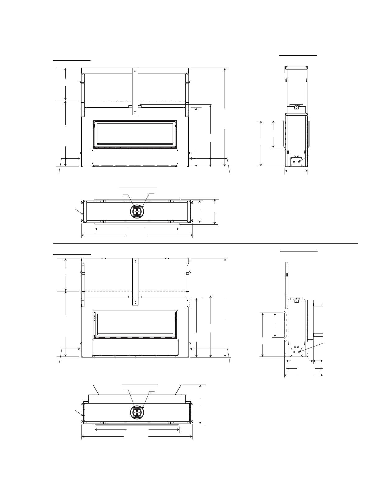
1.2 DIMENSIONS
5
FIGURE 1.2a
20.000”
40.000”
SHIPPING
HEIGHT
GAS
INLET
GAS
INLET
ACCESS SIDE
FIGURE 1.2c
5”
50.250”
67.375”
8”
37.188”
36.000”
13.500”
60.000”
EXTENDED
HEIGHT
ELECTRICAL
INLET
15.000”
FIGURE 1.2b
Two sided
16.250”
28.000”
ELECTRICAL
INLET
13.500”
FIGURE 1.2d
20.000”
40.000”
SHIPPING
HEIGHT
GAS
INLET
GAS
INLET
ACCESS SIDE
FIGURE 1.2f
5”
8”
37.188”
36.000”
23.500”
60.000”
EXTENDED
HEIGHT
ELECTRICAL
INLET
16.250”
28.000”
FIGURE 1.2e
One side
17.500”
23.500”
24.250”
ELECTRICAL
INLET
6.000”
50.250”
67.375”
W415-0745 / 02.16.09
6
1.3 INSTALLATION OVERVIEW
FIGURE 1.3
See the section
“FRAMING MINIMUM
MANTEL
CLEARANCES”
See the section
“FRAMING MINIMUM CLEARANCE TO
COMBUSTIBLE
ENCLOSURES” for
drywall (or other
combustible
material)”
See the section
“VENTING - VENTING
LENGTHS AND AIR TERMINAL
LOCATIONS”
See the section
“FRAMING”
See the section
“FRAMING”
Side
Wall
See the section
“ANTI CONDENSATION
CONTROL SWITCH”
See the section
“CONTROL ACCESS”
for the control box.
See the section
“FRAMING MINIMUM
CLEARANCE
TO COMBUSTIBLE
ENSLOSURES”
for noncombustible
materials such
as tile, marble,
granite, etc.
See the section
“REMOTE
RECEIVER
INSTALLATION”.
W415-0745 / 02.16.09

1.4 GENERAL INSTRUCTIONS
Always light the pilot whether for the first time or if the gas supply has ran out, with the glass door
Provide adequate accessibility clearance for servicing and operating the fireplace.
Never obstruct the front opening of the fireplace.
Objects placed in front of the fireplace must be kept a minimum of 48” from the front face of the unit.
This product must be installed by a licensed plumber or gas fitter when installed within the commonwealth
High Pressure will damage valve. Disconnect gas supply piping before pressure testing gas line at test pressures
above 1/2 psig. Close the manual shut-off valve before pressure testing gas line at test pressures equal to or
!
WARNING
opened or removed.
Provide adequate ventilation.
of Massachusetts.
Fire risk. Explosion Hazard.
less than 1/2 psig.
7
Use only Wolf Steel approved optional accessories and replacement parts with this appliance. Using non-listed
accessories (blowers, doors, louvres, trims, gas components, venting components, etc.) could result in a safety
hazard and will void the warranty and certification.
THIS GAS FIREPLACE SHOULD BE INSTALLED AND SERVICED BY A QUALIFIED INSTALLER to conform with local
codes. Installation practices vary from region to region and it is important to know the specifics that apply to your area, for
example in Massachusetts State:
• The fireplace damper must be removed or welded in the open position prior to installation of a fireplace insert or gas log.
• The appliance off valve must be a “T” handle gas cock.
• The flexible connector must not be longer than 36 inches.
• A Carbon Monoxide detector is required in all rooms containing gas fired appliances.
• The appliance is not approved for installation in a bedroom or bathroom unless the unit is a direct vent sealed
combustion product.
The installation must conform with local codes or, in absence of
local codes, the National Gas and Propane Installation Code
CSA B149.1 in Canada, or the National Fuel Gas Code,
ANSI Z223.1 / NFPA 54 in the United States. Suitable for mobile
home installation if installed in accordance with the current
standard CAN/CSA Z240MH Series, for gas equipped mobile
homes, in Canada or ANSI Z223.1 and NFPA 54 in the United
States.
When the fireplace is installed directly on carpeting, vinyl tile or other combustible material other than wood flooring, the
fireplace shall be installed on a metal or wood panel extending the full width and depth.
www.ncertied.org
We suggest that our gas
heart products be installed
and serviced by professionals
who are certied in the U.S.
by the National Fireplace
®
Institute
(NFI) as NFI Gas
Specialists
4.1
The optional heat circulating blower is supplied with a cord.
The junction box must be electrically connected and grounded in accordance with local codes. In the absence
of local codes, use the current CSA C22.1 Canadian Electrical Code in Canada or the ANSI/NFPA 70 National
Electrical Code in the United States.
W415-0745 / 02.16.09

8
1.5 SHIPPING HANDELS
IMPORTANT
This heater, fully dressed (not including fi nishing
material, cement board or framing), weighs 300
lbs. Ensure there is adequate support for the
heater and fi nishing material.
1.5.1 Lift up and secure the framing kit, see
“STEEL STUD FRAMING KIT” section for
instructions.
1.5.2 Insert the shipping handles (not supplied)
by placing the tabs in the desired slots on
both sides of the heater and lifting upwards
to secure in place.
1.5.3 Remove handles once the heater is in its
preferred location. Use shipping brackets
to secure base of unit.
FIGURE 1.5
1.6 GENERAL INFORMATION
FOR YOUR SATISFACTION, THIS FIREPLACE HAS BEEN TEST-FIRED TO ASSURE ITS OPERATION AND
QUALITY!
Maximum input is 30,000 BTU/hr for natural gas and propane. When the fi replace is installed at elevations
above 4,500ft, and in the absence of specifi c recommendations from the local authority having jurisdiction, the
certifi ed high altitude input rating shall be reduced at the rate of 4% for each additional 1,000ft.
Maximum output is 24,000 BTU/hr at an effi ciency of 79% for natural gas and propane.
Minimum inlet gas supply pressure is 4.5 inches water column for natural gas and 11 inches water column for
propane.
Maximum inlet gas pressure is 7 inches water column for natural gas and 13 inches water column for propane. Manifold pressure under fl ow conditions is 3.5 inches water column for natural gas and 10 inches water
column for propane.
This fi replace is approved for bathroom, bedroom and bed-sitting room installations and is certifi ed for mobile
home installation.
This fi replace is only for use with the type of gas indicated on the rating plate. This fi replace is not con-
vertible for use with other gases, unless a certifi ed kit is used.
There are two switches that control the function of the appliance. One on the receiver that must be placed in
the middle position. The other is on the control module that must be in the “I” position, which denotes on. If
these switches aren’t in these locations the fi replace will not work, see “REMOTE RECEIVER INSTALLATION”
and “CONTROL MODULE” section.
Expansion / contraction noises during heating up and cooling down cycles are normal and are to be expected.
Change in fl ame appearance from “HI” to “LO” is more evident in natural gas than in propane.
NOTE: The protective wrap on plated parts is best removed when the assembly is at room temperature
but this can be improved if the assembly is warmed, using a hair dryer or similar heat source.
This fi replace is equipped with a remote control system, which requires batteries (supplied) to be installed. The
transmitter takes 3 “AAA” batteries and in the case of a power failure the receiver takes 4 “AA” batteries.
W415-0745 / 02.16.09

1.7 CARE OF GLASS
f
DO NOT CLEAN GLASS WHEN HOT! DO NOT USE ABRASIVE
CLEANERS TO CLEAN GLASS.
Buff lightly with a clean dry soft cloth. Clean the glass after the first 10
hours of operation with a recommended fireplace glass cleaner.
Thereafter clean as required. If the glass is not kept clean permanent
discoloration and / or blemishes may result.
1.8 CARE OF PLATED PARTS
If the appliance is equipped with plated parts, you must clean
operating the appliance for the first time. Use a glass cleaner or vinegar and towel to clean. If not cleaned properly before
operating for the first time, the marks can cause permanent blemishes on the plating. After the plating is cured, the
fingerprints and oils will not affect the finish and little maintenance is required, just wipe clean as needed.
Prolonged high temperature burning with the door ajar may cause a permanent rain bowing effect on the lower edge of a
gold plated door (applies to wood product only).
NOTE: The protective wrap on plated parts is best removed when the assembly is at room temperature but this
can be improved if the assembly is warmed, using a hair dryer or similar heat source.
!
WARNING
HOT GLASS WILL
CAUSE BURNS.
DO NOT TOUCH GLASS
UNTIL COOLED.
NEVER ALLOW CHILDREN
TO TOUCH GLASS.
5.1
ingerprints or other marks from the plated surfaces before
6.1
9
W415-0745 / 02.16.09
10
A
2.0 VENTING
!
WARNING
Risk of fire, maintain specified air space clearances to vent pipe and appliance.
THIS FIREPLACE USES A 5" EXHAUST / 8" AIR INTAKE VENT PIPE SYSTEM.
Refer to the section applicable to your installation.
For safe and proper operation of the fireplace follow the venting instruction exactly. Deviation from the minimum
vertical vent length can create difficulty in burner start-up and/or carboning. Under extreme vent configurations,
allow several minutes (5-15) for the flame to stabilize after ignition. Vent lengths that pass through unheated
spaces (attics, garages, crawl spaces) should be insulated with the insulation wrapped in a protective sleeve to
minimize condensation. Provide a means for visually checking the vent connection to the fireplace after the
fireplace is installed. Use a firestop, vent pipe shield or attic insulation shield when penetrating interior walls, floor
or ceiling.
NOTE: If for any reason the vent air intake system is disassembled; reinstall per the instructions provided
for the initial installation.
2.1 VENTING LENGTHS AND COMPONENTS FOR DIRECT VENT INSTALLATIONS
Use only Wolf Steel, Simpson Dura-Vent, Selkirk Direct Temp, American Metal Amerivent or Metal-Fab venting components. Minimum and maximum vent lengths, for both horizontal and vertical installations, and air terminal locations for
either system are set out in this manual and must be adhered to. For Simpson Dura-Vent, Selkirk Direct Temp, American
Metal Amerivent and Metal-Fab follow the installation procedure provided with the venting components.
starter adaptor must be used with the following vent systems and may be purchased from the corresponding supplier:
7.2
PART 5" / 8" SUPPLIER WEBSITE
Duravent W175-0170 Wolf Steel www.duravent.com
Amerivent 5DSC-N2 American Metal www.americanmetalproducts.com
Direct Temp 5DT-AA Selkirk www.selkirkcorp.com
SuperSeal 5DDA Metal-Fab www.mtlfab.com
For vent systems that provide seals on the inner exhaust flue, only the outer air intake joints must be sealed using a red high
temperature silicone (RTV). This same sealant may be used on both the inner exhaust and outer intake vent pipe joints of all
other approved vent systems except for the exhaust vent pipe connection to the fireplace flue collar which must be sealed
using the black high temperature sealant Mill Pac.
When using Wolf Steel venting components, use only approved Wolf Steel rigid / flexible components with the following
termination kits: wall terminal kit GD422-1, GD422R-1, or 1/12 to 7/12 pitch roof terminal kit GD410, 8/12 to 12/12 roof
terminal kit GD411, flat roof terminal kit GD412 or periscope kit GD401 (for wall penetration below grade). With flexible
venting, in conjunction with the various terminations, use either the 5 foot vent kit GD420 or the 10 foot vent kit GD430.
For optimum flame appearance and fireplace performance, keep the vent length and number of elbows to a minimum.
The air terminal must remain unobstructed at all times. Examine the air terminal at least once a year to verify that it is
unobstructed and undamaged.
Rigid and flexible venting systems must not be combined. Different venting manufacturer components must not be
combined.
These vent kits allow for either horizontal or vertical venting of the fireplace. The maximum allowable horizontal run is 20 feet.
The maximum allowable vertical vent length is 40 feet. The maximum number of vent connections
vertically (excluding the fireplace and the air terminal connections) when using flexible venting.
* For Simpson Dura-Vent, Selkirk
Direct Temp, American Metal
Amerivent and Metal-Fab follow the
installation procedure found on the
website for your venting supplier.
is
two horizontally or three
Horizontal runs may have a 0” rise per foot however for optimum performance it is recommended that all horizontal runs
have a minimum 1/4” rise per foot using flexible venting. For safe and proper operation of the fireplace, follow the venting
instructions exactly.
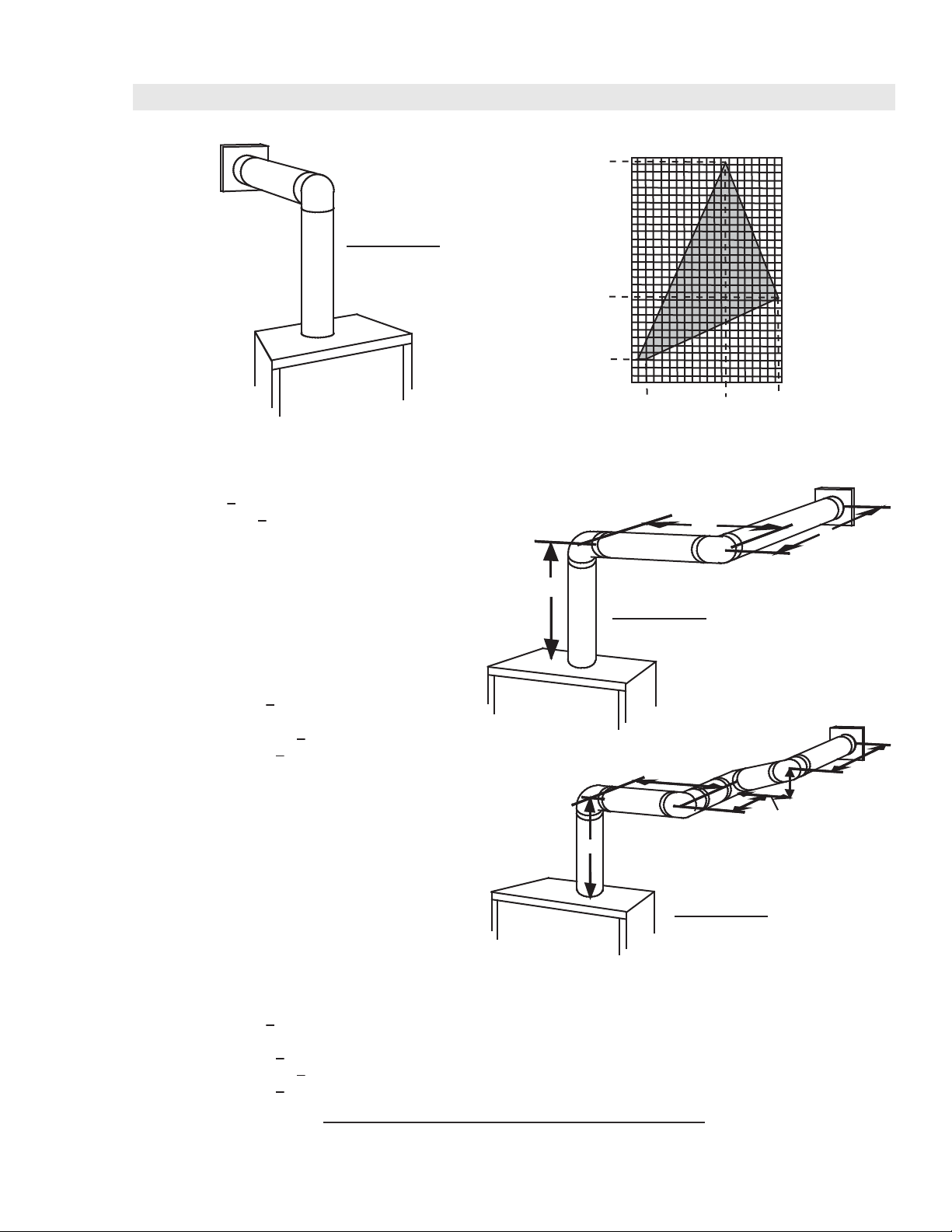
When terminating vertically, the vertical rise is a minimum 3 feet and a maximum 40 feet from the top of the fireplace.
8.3
W415-0745 / 02.16.09
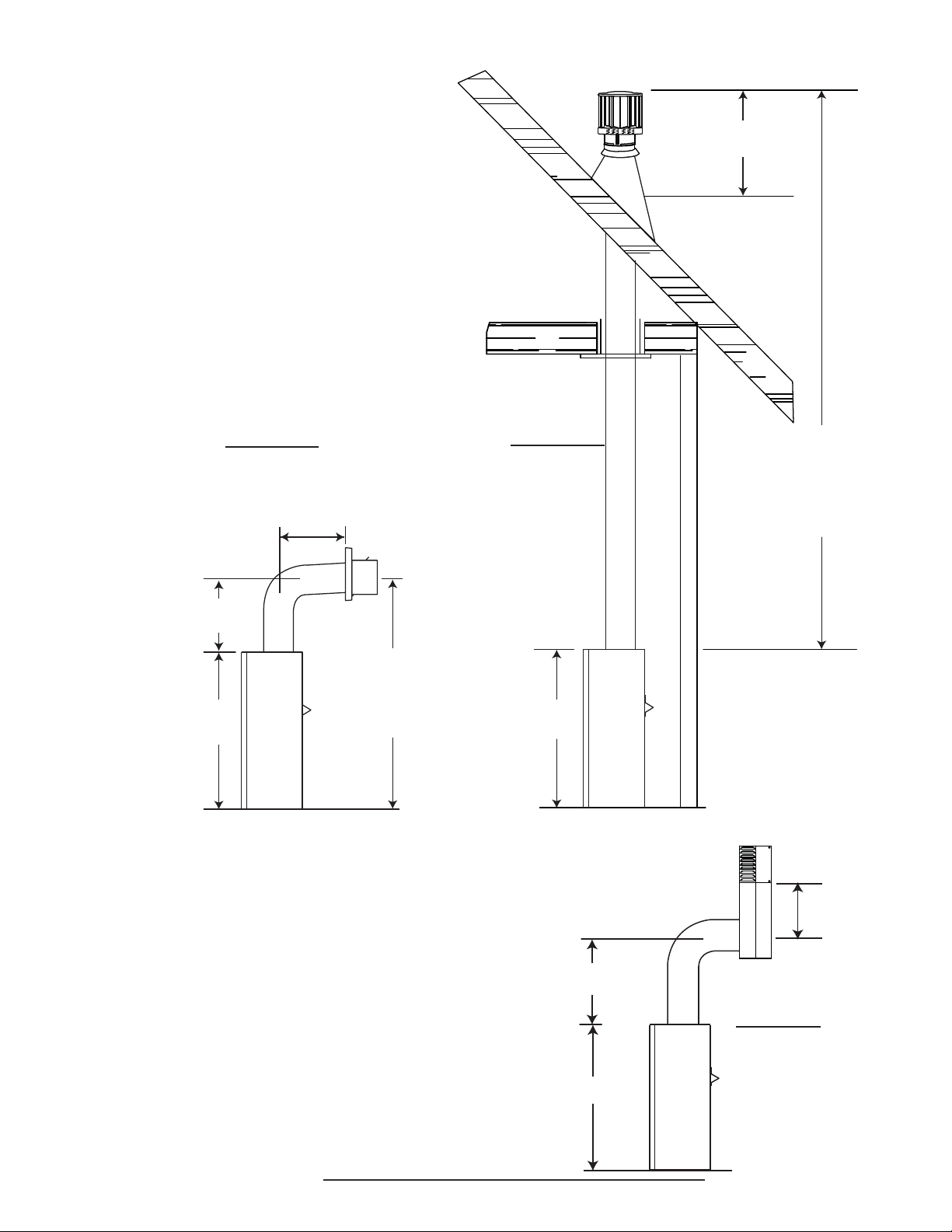
16” MINIMUM
11
FIGURE 2.1a
24”
MAXIMUM
15” MINIMUM
51”
MINIMUM
PLUS
36”
RISE
2.2 PERISCOPE TERMINATION
Use the periscope kit to locate the air termination above grade. The periscope must
be installed so that when final grading is completed, the bottom air slot is located a
minimum 12” above grade. The maximum allowable vent lengths depends on the
appliance, as illustrated.
FIGURE 2.1b
36”
40 FEET
MAXIMUM
3 FEET
MINIMUM
12”
MINIMUM
TO GRADE
30” MINIMUM
36”
FIGURE 2.2
9.1
W415-0745 / 02.16.09
12
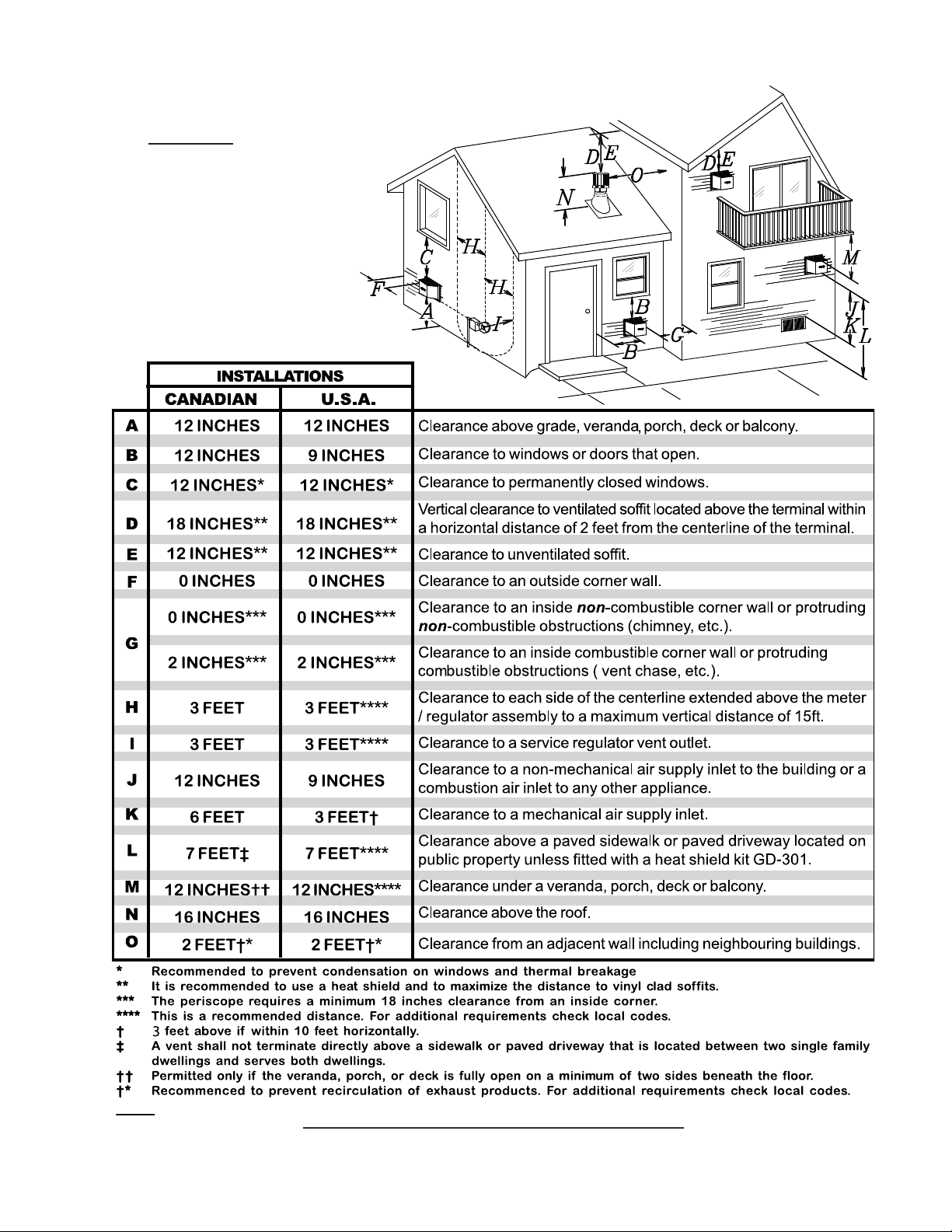
2.3 MINIMUM AIR TERMINAL LOCATION CLEARANCES
FIGURE 2.3
NOTE: Clearances are in accordance with local installation codes and the requirements of the gas supplier.
12.1
W415-0745 / 02.16.09
2.4 VENT APPLICATION FLOW CHART
TOP EXIT
13
Horizontal Termination
Vertical rise is equal
to or greater than the
horizontal run
Horizontal run +
vertical rise to
maximum of 40 feet
2.5 DEFINITIONS
For the following symbols used in the venting calculations and examples are:
> - greater than
> - equal to or greater than
< - less than
< - equal to or less than
HT - total of both horizontal vent lengths (Hr) and offsets (Ho) in feet
HR - combined horizontal vent lengths in feet
HO - offset factor: .03 (total degrees of offset - 90°*) in feet
VT - combined vertical vent lengths in feet
Vertical rise
is less than
horizontal run
Horizontal run +
vertical rise to
maximum of 24.75
feet
4.2 times the
vertical rise equal
to or greater than
the horizontal run
Vertical Termination
Vertical rise is equal
to or greater than
the horizontal run
Horizontal run +
vertical rise to
maximum of 40 feet
Vertical rise is less
than horizontal run
Horizontal run +
vertical rise to
maximum of 40
feet
3 times the
vertical rise equal
to or greater than
the horizontal run
13.1
14.1
2.6 ELBOW VENT LENGTH VALUES
FEET INCHES
1° 0.03 0.5
15° 0.45 6.0
30° 0.9 11.0
45° 1.35 16.0
90°* 2.7 32.0
* The first 90° offset has a zero value and is shown in the formula as - 90°
15.1
W415-0745 / 02.16.09
14
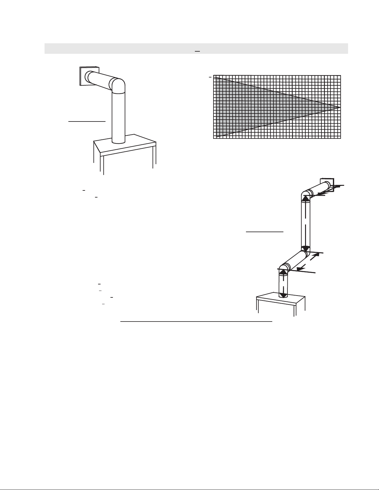
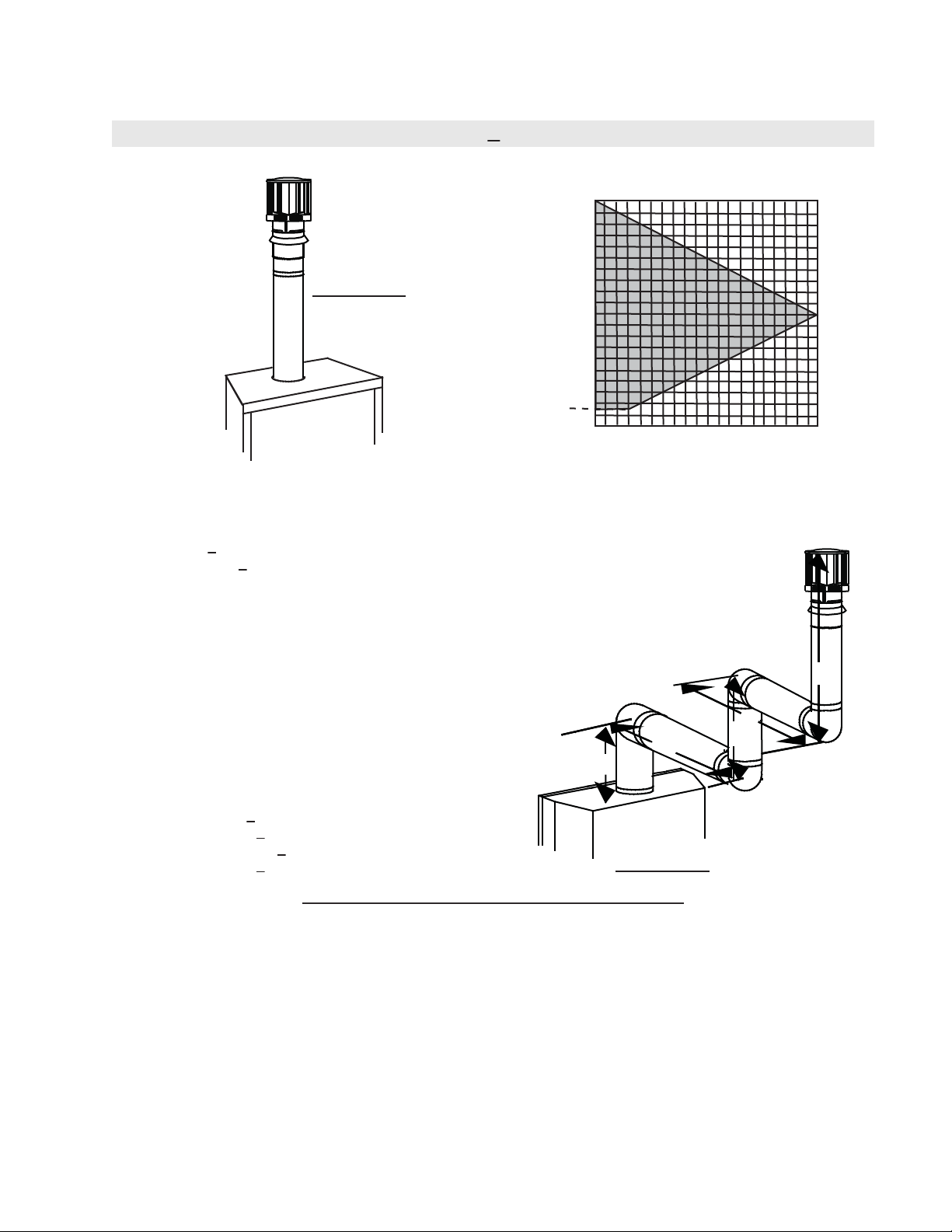
2.7 HORIZONTAL TERMINATION
(HT) < (VT)
Simple venting configuration (only one 90° elbow)
See graph to determine the required vertical rise VT for the
required horizontal run H
40
39
30
REQUIRED
FIGURE 2.7a
VERTICAL
RISE IN
FEET VT
20
10
0
2.5 5 7.5 10 12.5 15
HORIZONTAL VENT RUN PLUS OFFSET IN FEET H
The shaded area within the lines represents acceptable
values for HT and VT
For vent configurations requiring more than one 90° elbow, the following formulas apply:
Formula 1: H
Formula 2: HT + V
< V
T
T
< 40 feet
T
Example 1:
= 3 FT
V
1
V
= 8 FT
2
V
= V
+ V
T
H
= 2.5 FT
1
H
= 2 FT
2
= H
H
R
H
= .03 (three 90° elbows - 90°) = .03 (270° - 90°) = 5.4 FT
O
H
= H
T
H
+ V
T
= 3 + 8 = 11 FT
1
2
+ H
= 2.5 + 2 = 4.5 FT
1
2
+ H
= 4.5 + 5.4 = 9.9 FT
R
O
= 9.9 + 11 = 20.9 FT
T
FIGURE 2.7b
90°
90°
90°
.
T
17.5 20
T
H
2
V
2
H
1
Formula 1: HT < V
9.9 < 11
Formula 2: HT + V
20.9 < 40
T
< 40 FT
T
Since both formulas are met, this vent configuration is acceptable.
16.1
V
1
W415-0745 / 02.16.09
15
V
V
V
V
Simple venting configuration (only one 90° elbow)
FIGURE 2.7c
(HT) > (VT)
REQUIRED
VERTICAL
See graph to determine the required vertical rise VT for the
required horizontal run H
150
147”
100
.
T
RISE IN
INCHES V
T
57”
50
15”
0
515
2’
10
12.5’
19.5’
20
HORIZONTAL VENT RUN PLUS OFFSET IN FEET H
T
The shaded area within the lines represents acceptable
values for HT and VT
For vent configurations requiring more than one 90° elbow, the following formulas apply:
Formula 1: H
Formula 2: HT + V
Example 2:
= VT = 6 FT
1
H
= 3 FT
1
H
= 5 FT
2
H
= H
R
1
H
= .03 (two 90° elbows - 90°) = .03 (180° - 90°) = 2.7 FT
O
H
= H
T
R
H
+ V
T
T
< 4.2 V
T
+ H
= 3 + 5 = 8 FT
2
+ H
= 8 + 2.7 = 10.7 FT
O
= 10.7 + 6 = 16.7 FT
T
< 24.75 feet
T
90°
V
1
H
1
H
2
90°
FIGURE 2.7d
Formula 1: HT < 4.2 V
4.2 VT = 4.2 x 6 = 25.2 FT
Formula 2: HT + V
16.7 < 24.75
Since both formulas are met, this vent configuration is acceptable.
Example 3:
= 4 FT
1
= 1.5 FT
2
= V
+ V
T
H
= 2 FT
1
H
= 1 FT
2
H
= 1 FT
3
H
= 1.5 FT
4
H
= H
R
H
= .03 (four 90° elbows - 90°) = .03 (360° - 90°) = 8.1 FT
O
H
= H
T
H
+ V
T
= 4 + 1.5 = 5.5 FT
1
2
+ H2 + H
1
+ H
R
= 13.6 + 5.5 = 19.1 FT
T
+ H4 = 2 + 1 + 1 + 1.5 = 5.5 FT
3
= 5.5 + 8.1 = 13.6 FT
O
Formula 1: HT < 4.2 V
4.2 VT = 4.2 x 5.5 = 23.1 FT
T
< 24.75 FT
T
T
90°
90°
90°
H
1
90°
V
1
V
H
H
2
3
H
4
2
FIGURE 2.7e
13.6 < 23.1
Formula 2: HT + V
19.1 < 24.75
< 24.75 FT
T
Since both formulas are met, this vent configuration is acceptable.
16.4
W415-0745 / 02.16.09
16
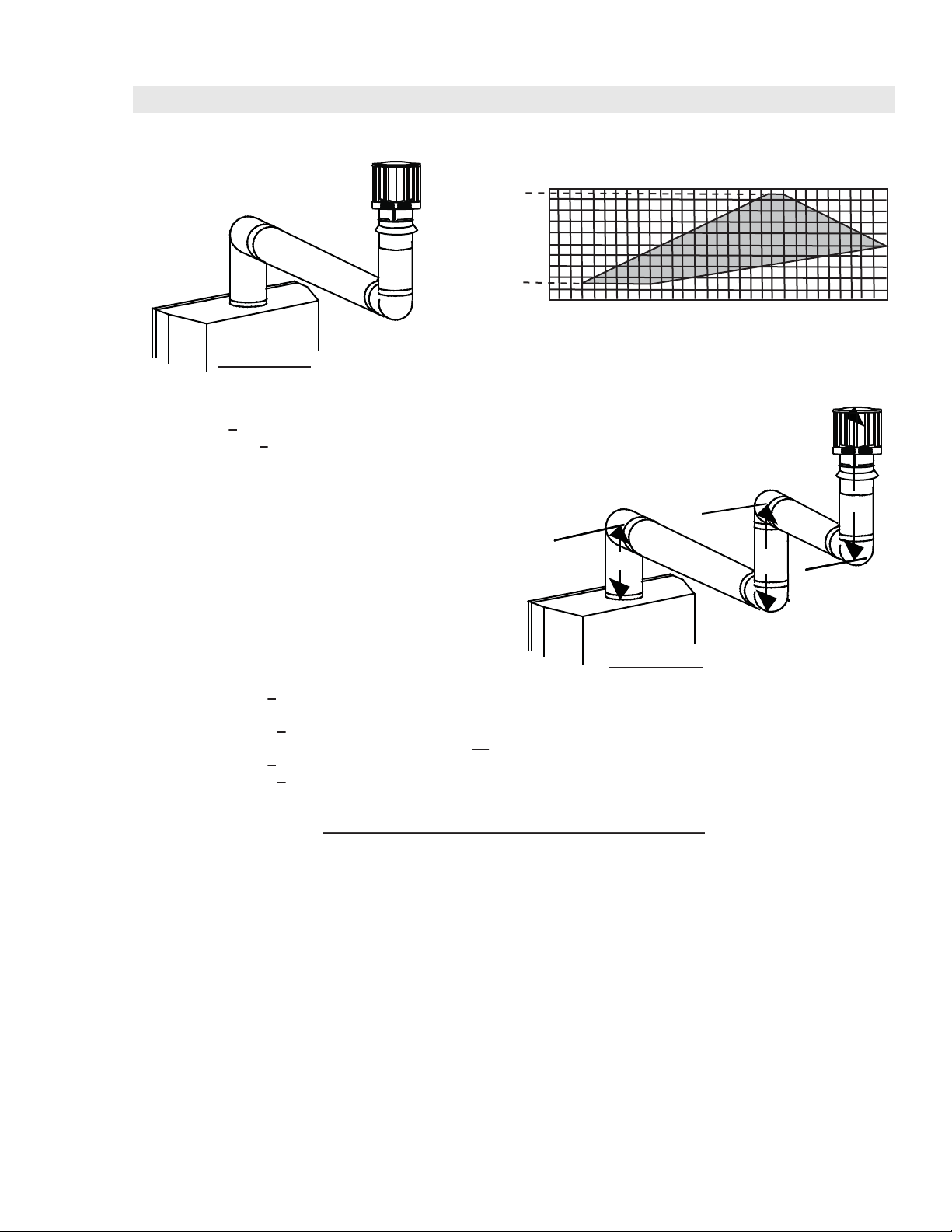
2.8 VERTICAL TERMINATION
(HT) < (VT)
Simple venting configurations.
See graph to determine the required vertical rise V
required horizontal run HT.
40
30
FIGURE 2.8a
REQUIRED
VERTICAL
20
RISE IN
FEET V
T
10
3
0
5101520
HORIZONTAL VENT RUN PLUS OFFSET IN FEET H
The shaded area within the lines represents acceptable
values for HT and VT
For vent configurations requiring more than zero 90° elbows the following formulas apply:
Formula 1: H
Formula 2: HT + V
< V
T
T
< 40 feet
T
for the
T
T
Example 6:
V
= 5 FT
1
V
= 6 FT
2
V
= 10 FT
3
V
= V
+ V2 + V3 = 5 + 6 + 10 = 21 FT
T
1
H
= 8 FT
1
H
= 2.5 FT
2
H
= H
+ H
R
H
= .03 (four 90° elbows - 90°)
O
= .03 (360° - 90°) = 8.1 FT
H
= H
T
H
+ V
T
Formula 1: HT < 3.5 V
18.6 < 21
Formula 2: HT + V
39.6 < 40
= 8 + 2.5 = 10.5 FT
1
2
+ H
= 10.5 + 8.1 = 18.6 FT
R
O
= 18.6 + 21 = 39.6 FT
T
T
T
< 40 FT
Since both formulas are met, this vent configuration is acceptable.
90°
H
V
1
FIGURE 2.8b
90°
V
3
H
2
V
1
2
90°
90°
18.1
W415-0745 / 02.16.09
17
(HT) > (VT)
Simple venting configurations.
See graph to determine the required vertical rise V
required horizontal run H
20
19
REQUIRED
VERTICAL
RISE IN
FEET V
10
T
3
0
5101520
HORIZONTAL VENT RUN PLUS OFFSET IN FEET H
FIGURE 2.8c
The shaded area within the lines represents acceptable
values for H
For vent configurations requiring more than two 90° elbows the following formulas apply:
Formula 1: H
Formula 2: HT + V
< 3V
T
T
< 40 feet
T
Example 2:
V
= 2 FT
1
V
= 1 FT
2
V
= 1.5 FT
3
V
= V
+ V2 + V3 = 2 + 1 + 1.5 = 4.5 FT
T
1
H
= 6 FT
1
H
= 2 FT
2
H
= H
+ H
R
H
= .03 (four 90° elbows - 90°)
O
= .03 (360° - 90°) = 8.1 FT
H
= H
T
H
+ V
T
= 6 + 2 = 8 FT
1
2
+ H
= 8 + 8.1 = 16.1 FT
R
O
= 16.1 + 4.5 = 20.6 FT
T
90°
V
1
FIGURE 2.8d
for the
T
25 30
T
and VT
T
.
T
90°
V
H
2
H
1
V
2
3
90°
90°
Formula 1: HT < 3V
3VT = 3 x 4.5 = 13.5 FT
T
16.1 < 13.5
Since this formula is not met, this vent configuration is unacceptable.
Formula 2: HT < VT = 40 feet
20.6 < 40
Since only formula 2 is met, this vent configuration is unacceptable and a new fireplace location or vent configuration will
need to be established to satisfy both formulas.
18.1_2
W415-0745 / 02.16.09
18
3.0 INSTALLATION
!
Follow the venting instructions exactly.
All inner exhaust and outer intake vent pipe joints may be sealed using either red RTV high temp
silicone sealant W573-0002 (not supplied) or black high temp mill pac W573-0007 (not supplied) with
the exception of the fireplace exhaust flue collar which must be sealed using mill pac.
If using pipe clamps to connect vent components, 3 screws must also be used to ensure the
connection cannot slip off.
Do not clamp the flexible vent pipe.
Risk of fire, explosion or asphyxiation. Improper support of the entire venting system may allow vent
to sag and separate. Use vent runs support and connect vent sections per installation instructions.
Risk of fire, do not allow loose materials or insulation to touch the vent pipe. Remove insulation to
allow for the installation of the attic shield and to maintain clearances to combustibles.
3.1 WALL AND CEILING PROTECTION
WARNING
!
WARNING
Do not fill the space between the vent pipe and enclosure with any type of material. Do not pack insulation or
combustibles between ceiling firestops. Always maintain specified clearances around venting and firestop
systems. Install wall shields and firestops as specified. Failure to keep insulation or other materials away from
vent pipe may cause fire.
For optimum performance it is recommended that all horizontal runs have a minimum of 1/4” rise per foot using
fl exible venting. For safe and proper operation of the fi replace, follow the venting instructions exactly.
W415-0745 / 02.16.09
 Loading...