

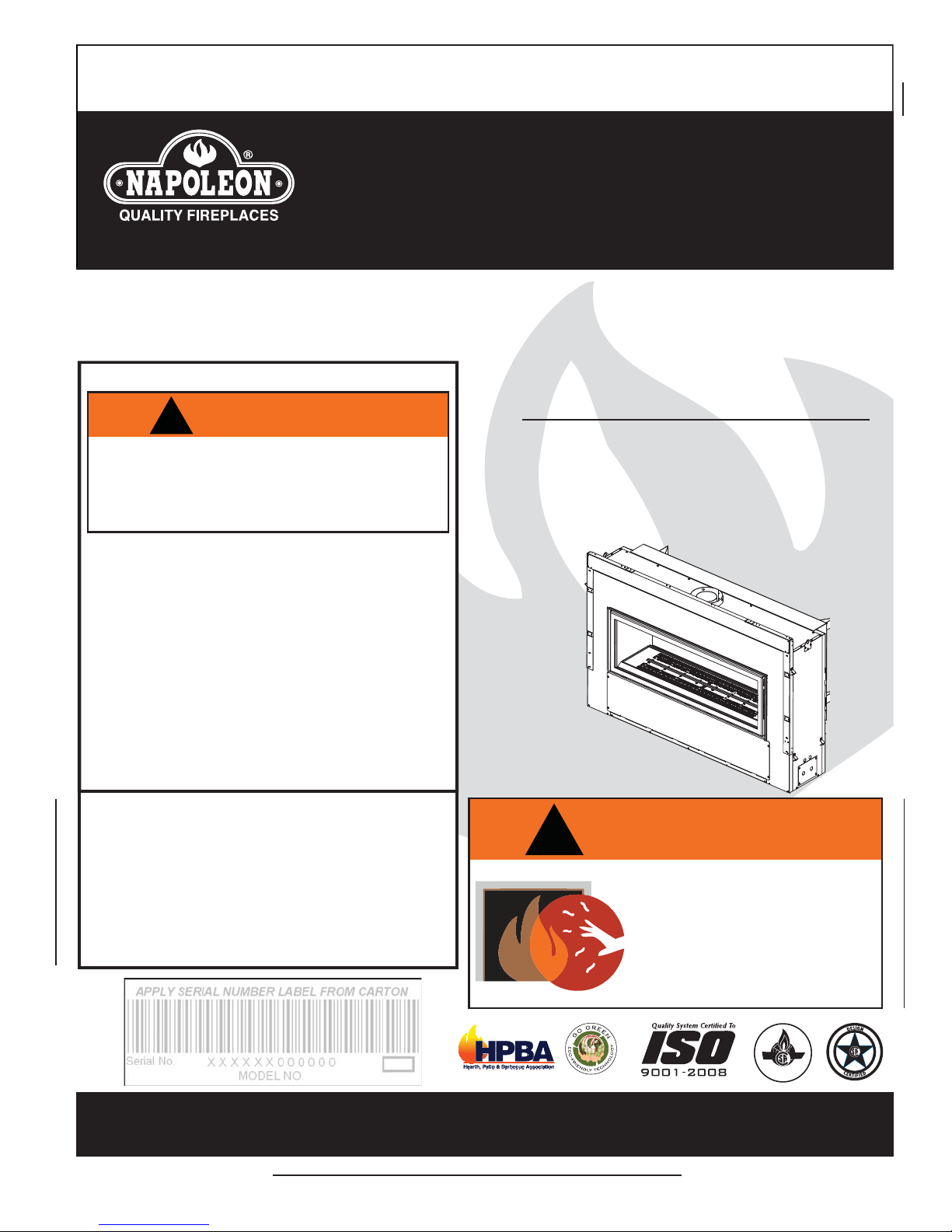
Napoleon LHD50N2, LHD50P, LHD50P2 Installation And Operating Instructions Manual
INSTALLER: LEAVE THIS MANUAL WITH THE APPLIANCE.
CONSUMER: RETAIN THIS MANUAL FOR FUTURE REFERENCE.
NEVER LEAVE CHILDREN OR OTHER AT RISK INDIVIDUALS ALONE WITH THE APPLIANCE.
INSTALLATION AND
OPERATING INSTRUCTIONS
CERTIFIED UNDER CANADIAN AND AMERICAN NATIONAL STANDARDS: ANSI Z21.50 CSA 2.22 FOR VENTED GAS APPLIANCES.
CERTIFIED UNDER CANADIAN AND AMERICAN NATIONAL STANDARDS: ANSI Z21.50 CS A 2.2 2 FO R VE NTE D GA S FIR EPL ACE S.
LHD50N
CERTIFIED FOR CANADA AND UNITED STATES USING ANSI/CSA METHODS.
SAFETY INFORMATION
!
WARNING
If the information in these instructions
are not followed exactly, a fi re or
explosion may result causing property
damage, personal injury or loss of life.
- Do not store or use gasoline or other fl ammable
vapors and liquids in the vicinity of this or any
other appliance.
- WHAT TO DO IF YOU SMELL GAS:
• Do not try to light any appliance.
• Do not touch any electrical switch; do not use
any phone in your building.
• Immediately call your gas supplier from a
neighbour’s phone. Follow the gas supplier’s
instructions.
• If you cannot reach your gas supplier, call the
fi re department.
- Installation and service must be performed by a
qualifi ed installer, service agency or the supplier.
This appliance may be installed in an aftermarket,
permanently located, manufactured home (USA
only) or mobile home, where not prohibited by
local codes.
This appliance is only for use with the type of gas
indicated on the rating plate. This appliance is
not convertible for use with other gases, unless a
certifi ed kit is used.
!
LHD50N2
NATURAL GAS
LHD50P
LHD50P2
PROPANE
LHD50N ILLUSTRATED
WARNING
HOT GLASS WILL CAUSE
BURNS.
DO NOT TOUCH GLASS UNTIL
COOLED.
NEVER ALLOW CHILDREN TO
TOUCH GLASS.
1
Wolf Steel Ltd., 24 Napoleon Rd., Barrie, ON, L4M 0G8 Canada /
$10.00
$10.00
Phone (705)721-1212 • Fax (705)722-6031 • www.napoleonfi replaces.com • ask@napoleonproducts.com
103 Miller Drive, Crittenden, Kentucky, USA, 41030
CERTIFIED
1.36A
W415-0745 / D / 11.30.11

2
TABLE OF CONTENTS
1.0 INSTALLATION OVERVIEW 3
2.0 INTRODUCTION 4
2.1 DIMENSIONS 5
2.2 GENERAL INSTRUCTIONS 6
2.3 GENERAL INFORMATION 7
2.4 RATING PLATE / LIGHTING INSTRUCTION LOCATION 8
2.5 SHIPPING HANDLES 9
3.0 VENTING 10
3.1 VENTING LENGTHS AND COMPONENTS FOR DIRECT VENT INSTALLATIONS 10
3.2 TYPICAL VENT INSTALLATIONS 11
3.3 SPECIAL VENT INSTALLATION 12
3.3.1 PERISCOPE TERMINATION 12
3.4 MINIMUM AIR TERMINAL LOCATION CLEARANCES 13
3.5 VENT APPLICATION FLOW CHART 14
3.6 DEFINITIONS 14
3.7 ELBOW VENT LENGTH VALUES 14
3.8 HORIZONTAL TERMINATION 15
3.9 VERTICAL TERMINATION 17
4.0 INSTALLATION 19
4.1 WALL AND CEILING PROTECTION 19
4.1.1 HORIZONTAL INSTALLATION 20
4.1.2 VERTICAL INSTALLATION 20
4.2 USING FLEXIBLE VENT COMPONENTS 21
4.2.1 HORIZONTAL AIR TERMINAL INSTALLATION 21
4.2.2 VERTICAL AIR TERMINAL INSTALLATION 22
4.2.3 APPLIANCE VENT CONNECTION 23
4.3 MOBILE HOME INSTALLATION 23
4.4 GAS INSTALLATION 24
5.0 FRAMING 25
5.1 TWO SIDED APPLIANCE 26
5.2 ONE SIDE APPLIANCE 28
5.3 MINIMUM CLEARANCE TO COMBUSTIBLE ENCLOSURES 30
5.4 INSTALLING CEMENT BOARD 33
5.5 MINIMUM COMBUSTIBLE MANTEL CLEARANCES 35
6.0 FINISHING 36
6.1 DOOR REMOVAL / INSTALLATION 36
6.2 GLASS MEDIA INSTALLATION 38
6.3 OPTIONAL ROCK PLACEMENT 39
6.4 LOGO PLACEMENT 39
6.5 UNIQUE INSTALLATIONS 39
7.0 ELECTRICAL CONNECTION 40
7.1 HARD WIRING CONNECTION 40
7.2 RECEPTACLE WIRING DIAGRAM 41
7.3 REMOTE RECEIVER INSTALLATION 41
7.4 SCHEMATIC 42
8.0 OPERATION 43
8.1 GENERAL TRANSMITTER LAYOUT 43
8.2 APPLIANCE OPERATION 43
8.3 HAND HELD REMOTE OPERATIONS 44
8.4 TEMPERATURE DISPLAY 44
8.5 ROOM THERMOSTAT 44
8.6 SMART THERMOSTAT 44
8.7 FLAME HEIGHT 45
8.8 CHILD PROOF FUNCTION 45
8.9 CRYSTALITES 45
8.10 LOW BATTERY / MANUAL BYPASS 46
8.11 IN THE EVENT OF A POWER FAILURE 46
8.12 CONTROL MODULE 46
8.13 ANTI CONDENSATION CONTROL SWITCH 46
9.0 OPERATING INSTRUCTIONS 47
10.0 ADJUSTMENT 48
10.1 RESTRICTING VERTICAL VENTS 48
10.2 PILOT BURNER ADJUSTMENT 48
10.3 VENTURI ADJUSTMENT 49
10.4 FLAME CHARACTERISTICS 49
11.0 MAINTENANCE 50
11.1 CONTROL ACCESS 50
11.2 VALVE TRAIN ASSEMBLY 51
11.3 VALVE REMOVAL 51
11.4 BURNER REMOVAL 52
11.5 CONTROL MODULE REMOVAL 52
11.6 IPI BOARD AND AC ADAPTOR ACCESS 52
11.7 LAMP REPLACEMENT 53
NOTE: Changes, other than editorial, are denoted by a vertical line in the margin.
W415-0745 / D / 11.30.11
11.8 LENS ASSEMBLY REPLACEMENT 53
11.9 PORCELAIN WRAP REMOVAL 54
11.10 DOOR LATCH REPLACEMENT 54
11.11 GLASS / DOOR REPLACEMENT 55
11.12 CARE OF GLASS 55
11.13 CARE OF PLATED PARTS 55
12.0 REPLACEMENTS 56
13.0 TROUBLESHOOTING 59
14.0 WARRANTY 62
15.0 SERVICE HISTORY 63
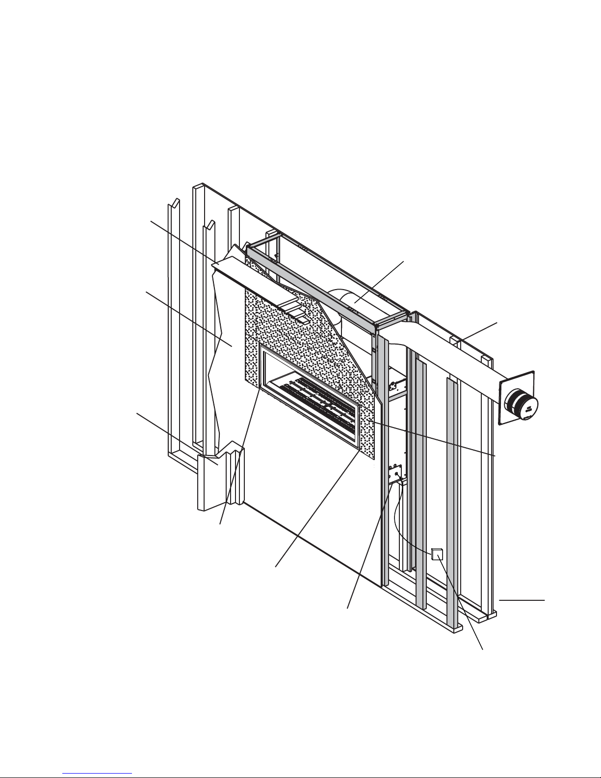
1.0 INSTALLATION OVERVIEW
See the section
“FRAMING MINIMUM
MANTEL
CLEARANCES”
See the section
“FRAMING MINIMUM CLEARANCE TO
COMBUSTIBLE
ENCLOSURES” for
drywall (or other
combustible
material)”
3
See the section
“VENTING - VENTING
LENGTHS AND AIR TERMINAL
LOCATIONS”
GD422R-1 Illustrated
See the section
“FRAMING”
See the section
“RATING PLATE / LIGHTING
INSTRUCTION LOCATION”
Side
Wall
See the section
“ANTI CONDENSATION
CONTROL SWITCH”
See the section
“CONTROL ACCESS”
for the control box.
See the section
“FRAMING MINIMUM
CLEARANCE
TO COMBUSTIBLE
ENSLOSURES”
for noncombustible
materials such
as tile, marble,
granite, etc.
Important: Extra
support may be
required
See the section
“REMOTE
RECEIVER
INSTALLATION”.
W415-0745 / D / 11.30.11

4
2.0 INTRODUCTION
• THIS APPLIANCE IS HOT WHEN OPERATED AND CAN CAUSE SEVERE BURNS IF CONTACTED.
• ANY CHANGES OR ALTERATIONS TO THIS APPLIANCE OR ITS CONTROLS CAN BE DANGEROUS
AND IS PROHIBITED.
• Do not operate appliance before reading and understanding operating instructions. Failure to operate
appliance according to operating instructions could cause fi re or injury.
• Risk of fi re or asphyxiation do not operate appliance with fi xed glass removed.
• Do not connect 110 volts to the control valve.
• Risk of burns. The appliance should be turned off and cooled before servicing.
• Do not install damaged, incomplete or substitute components.
• Risk of cuts and abrasions. Wear protective gloves and safety glasses during installation. Sheet metal edges
may be sharp.
• Do not burn wood or other materials in this appliance.
• Children and adults should be alerted to the hazards of high surface temperature and should stay away to
avoid burns or clothing ignition.
• Young children should be carefully supervised when they are in the same room as the appliance. Toddlers,
young children and others may be susceptible to accidental contact burns. A physical barrier is recommended
if there are at risk individuals in the house. To restrict access to an appliance, install an adjustable safety gate
to keep toddlers, young children and other at risk individuals out of the room and away from hot surfaces.
• Clothing or other fl ammable material should not be placed on or near the appliance.
• Due to high temperatures, the appliance should be located out of traffi c and away from furniture and draperies.
• Ensure you have incorporated adequate safety measure to protect infants/toddlers from touching hot surfaces.
• Even after the appliance is out, the glass and/or screen will remain hot for an extended period of time.
• Check with your local hearth specialty dealer for safety screens and hearth guards to protect children from hot
surfaces. These screens and guards must be fastened to the fl oor.
• Any safety screen or guard removed for servicing must be replaced prior to operating the appliance.
• The appliance is a vented gas-fi red appliance. Do not burn wood or other materials in the appliance
• It is imperative that the control compartments, burners and circulating blower and its passageway in the
appliance and venting system are kept clean. The appliance and its venting system should be inspected
before use and at least annually by a qualifi ed service person. More frequent cleaning may be required due
to excessive lint from carpeting, bedding material, etc. The appliance area must be kept clear and free from
combustible materials, gasoline and other fl ammable vapors and liquids.
• Under no circumstances should this appliance be modifi ed.
• This appliance must not be connected to a chimney fl ue pipe serving a separate solid fuel burning appliance.
• Do not use this appliance if any part has been under water. Immediately call a qualifi ed service technician to
inspect the appliance and to replace any part of the control system and any gas control which has been under
water.
• Do not operate the appliance with the glass door removed, cracked or broken. Replacement of the glass
should be done by a licensed or qualifi ed service person.
• Do not strike or slam shut the appliance glass door.
• When equipped with pressure relief doors, they must be kept closed while the appliance is operating to
prevent exhaust fumes containing carbon monoxide, from entering into the home. Temperatures of the exhaust
escaping through these openings can also cause the surrounding combustible materials to overheat and catch
fi re.
• Only doors / optional fronts certifi ed with the unit are to be installed on the appliance.
• Keep the packaging material out of reach of children and dispose of the material in a safe manner. As with all
plastic bags, these are not toys and should be kept away from children and infants.
• As with any combustion appliance, we recommend having your appliance regularly inspected and serviced as
well as having a Carbon Monoxide Detector installed in the same area to defend you and your family against
Carbon Monoxide.
• Ensure clearances to combustibles are maintained when building a mantel or shelves above the appliance.
Elevated temperatures on the wall or in the air above the appliance can cause melting, discolouration or
damage of decorations, a T.V. or other electronic components.
!
WARNING
W415-0745 / D / 11.30.11
3.2B

2.1 DIMENSIONS
20.000”
40.000”
SHIPPING
HEIGHT
OPERATING SIDE
37.188”
36.000”
5
Two sid ed
60.000”
EXTENDED
HEIGHT
16.250”
28.000”
ELECTRICAL
INLET
GAS
INLET
GAS
INLET
20.000”
40.000”
SHIPPING
HEIGHT
5”
50.250”
67.375”
OPERATING SIDE
8”
13.500”
37.188”
36.000”
ELECTRICAL
INLET
15.000”
60.000”
EXTENDED
HEIGHT
16.250”
28.000”
13.500”
One side
ELECTRICAL
INLET
GAS
INLET
5”
GAS
INLET
67.375”
50.250”
8”
23.500”
ELECTRICAL
INLET
17.500”
23.500”
6.000”
W415-0745 / D / 11.30.11
6
A
A
2.2 GENERAL INSTRUCTIONS
ALWAYS LIGHT THE PILOT WHETHER FOR THE FIRST TIME OR IF THE GAS SUPPLY HAS RUN OUT,
WITH THE GLASS DOOR OPENED OR REMOVED.
PROVIDE ADEQUATE CLEARANCE FOR SERVICING AND OPERATING THE APPLIANCE.
NEVER OBSTRUCT THE FRONT OPENING OF THE APPLIANCE.
OBJECTS PLACED IN FRONT OF THE APPLIANCE MUST BE KEPT A MINIMUM OF 48” FROM THE
SURFACES AROUND AND ESPECIALLY ABOVE THE APPLIANCE CAN BECOME HOT. AVOID CONTACT
WHEN THE APPLIANCE IS OPERATING.
HIGH PRESSURE WILL DAMAGE VALVE. DISCONNECT GAS SUPPLY PIPING BEFORE PRESSURE TESTING GAS
LINE AT TEST PRESSURES ABOVE 1/2 PSIG. CLOSE THE MANUAL SHUT-OFF VALVE BEFORE PRESSURE
TESTING GAS LINE AT TEST PRESSURES EQUAL TO OR LESS THAN 1/2 PSIG.
USE ONLY WOLF STEEL APPROVED OPTIONAL ACCESSORIES AND REPLACEMENT PARTS WITH THIS APPLIANCE.
USING NON-LISTED ACCESSORIES (BLOWERS, DOORS, LOUVRES, TRIMS, GAS COMPONENTS, VENTING
COMPONENTS, ETC.) COULD RESULT IN A SAFETY HAZARD AND WILL VOID THE WARRANTY AND CERTIFICATION.
!
WARNING
PROVIDE ADEQUATE VENTILATION.
FRONT FACE OF THE UNIT.
FIRE RISK. EXPLOSION HAZARD.
THIS GAS APPLIANCE SHOULD BE INSTALLED AND SERVICED BY A QUALIFIED INSTALLER to
conform with local codes. Installation practices vary from region to region and it is important to know the
specifi cs that apply to your area, for example in Massachusetts State:
• This product must be installed by a licensed plumber or gas fi tter when installed within the commonwealth
of Massachusetts.
• The appliance damper must be removed or welded in the open position prior to installation of a appliance
insert or gas log.
• The appliance off valve must be a “T” handle gas cock.
• The fl exible connector must not be longer than 36 inches.
• A Carbon Monoxide detector is required in all rooms containing gas fi red appliances.
• The appliance is not approved for installation in a bedroom or bathroom unless the unit is a direct vent
sealed combustion product.
The installation must conform with local codes or, in
absence of local codes, the National Gas and Propane
Installation Code CSA B149.1 in Canada, or the National
Fuel Gas Code, ANSI Z223.1 / NFPA 54 in the United
States. Suitable for mobile home installation if installed in
accordance with the current standard CAN/CSA Z240MH
Series, for gas equipped mobile homes, in Canada or
NSI Z223.1 and NFPA 54 in the United States.
s long as the required clearance to combustibles is
maintained, the most desirable and benefi cial location
for an appliance is in the center of a building, thereby
allowing the most effi cient use of the heat created. The location of windows, doors and the traffi c fl ow in the
room where the appliance is to be located should be considered. If possible, you should choose a location
where the vent will pass through the house without cutting a fl oor or roof joist.
www.ncertied.org
We suggest that our gas
hearth products be installed
and serviced by professionals
who are certied in the U.S.
by the National Fireplace
Institute
®
(NFI) as NFI Gas
Specialists
If the appliance is installed directly on carpeting, vinyl tile or other combustible material other than wood
fl ooring, the appliance shall be installed on a metal or wood panel extending the full width and depth.
Some appliances have optional fans or blowers. If an optional fan or blower is installed, the junction box must
be electrically connected and grounded in accordance with local codes, use the current CSA C22.1 Canadian
Electrical Code in Canada or the ANSI/NFPA 70 National Electrical code in the United States.
W415-0745 / D / 11.30.11
4.1A
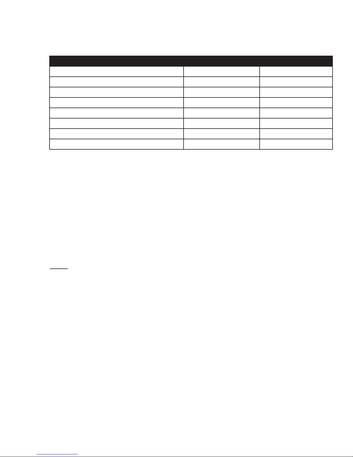
2.3 GENERAL INFORMATION
FOR YOUR SATISFACTION, THIS APPLIANCE HAS BEEN TEST-FIRED TO ASSURE ITS OPERATION AND
QUALITY!
Altitude (FT) 0-4,500 0-4500
Max. Input (BTU/HR) 30,000 30,000
Max. Output (BTU/HR) 24,000 24,000
Effi ciency (w/the fan on) 79% 79%
Min. Inlet Gas Supply Pressure 4.5" Water Column 11" Water Column
Max. Inlet Gas Supply Pressure 7" Water Column 13" Water Column
Manifold Pressure (Under Flow Conditions) 3.5" Water Column 10" Water Column
When the appliance is installed at elevations above 4,500ft, and in the absence of specifi c recommendations from the
local authority having jurisdiction, the certifi ed high altitude input rating shall be reduced at the rate of 4% for each ad-
ditional 1,000ft. Expansion / contraction noises during heating up and cooling down cycles are normal and are to
be expected. Change in fl ame appearance from “HI” to “LO” is more evident in natural gas than in propane.
7
LHD50
NG LP
This appliance is approved for bathroom, bedroom and bed-sitting room installations and is certifi ed for mobile
home installation.
This appliance is only for use with the type of gas indicated on the rating plate. This appliance is not
convertible for use with other gases, unless a certifi ed kit is used.
There are two switches that control the function of the appliance. One on the receiver that must be placed in
the middle position. The other is on the control module that must be in the “I” position, which denotes on. If
these switches aren’t in these locations the appliance will not work, see “REMOTE RECEIVER INSTALLATION” and “CONTROL MODULE” section.
NOTE: The protective wrap on plated parts is best removed when the assembly is at room temperature
but this can be improved if the assembly is warmed, using a hair dryer or similar heat source.
This appliance is equipped with a remote control system, which requires batteries (supplied) to be installed.
The transmitter takes 3 “AAA” batteries and in the case of a power failure the receiver takes 4 “AA” batteries.
W415-0745 / D / 11.30.11
8
*
PPROVED
F
O
BEDR
OOOO
MM,,BBAATTHHRR
OO
OO
MMANDBEDBEDSSIITTTTIINN
GG
R
OOMOOMN/CS
Z
240M
HSERI
E
S
GASS
EE
QQ
UU
II
PPPPEEDD
MMOOBBIILLEHOMM
EE
SS
,,
II
NN
CANCAN
AATTHH
II
SSUUSS
SS
T
ANDARD
ISNOTAPPLLII
CABCAB
LL
EE
UU
SS
EETTHH
EEST
ANDARRDD
FF
OO
UU
FFFFAAGGEE
AA
UU
GG
AZZAVECÉVA
C
U
ATION.HHOOMMOOLL
OOGGUU
ÉÉ
PP
OO
UU
RINSTBBIILLEESSII
SS
OO
NNIINNSSTTAALLLLAATTIIOONN
C
O
N
FORME
U
XEEXX
II
GG
ENCENCEESS
DDEELLAADDEE
SECSEC
UU
RRIITTÉÉEETTDD
EE
CCOONSTRUNSTRU
CC
TT
IIOONDEMA
I
S
ONSS
MMAANNUUFF
ACTURÉACTUR
EREELLAATTIIVVEEAA
UU
CC
RIITÈTÈRREEDDEE
MM
ESURESUREESS
DD
EE
SÉCSÉ
U
RIT
É
C
OO
NTNTRREE
LL
CODES OU RÈGLEMENTS LOCAUX, OU EN L’ABSENCE DE TELS RÈÈGLEMENTS LOCAUX, OU EN L’ABSENCE DE TELS
SE
O NOTO NOT
ADDADD
ANANYY M MAATERIATE
L
IANCE, WHICH WILANCE, WHICH W
LL
COME
WITH THE FLAMES, OTHER
A
T SUPPLIED B
UPPLIED B
YY
THE HE
ACTURER WITH THE
RER WITH THE
.APPLIANCE.
M CLEARANCE
LEARANCE TTOO
LE MAATERIALS:TERIALS:
0”
0”
ONE SIDEDD 23.75" 23.75"
5” 13.5”
NGNG
0”
0”
00450
0
F
T
(
30,
3.3.
55
WWAATT
EERR
C
OLUU
MM
NN
//D'UD'U
NN
EE
55CCO
U
7..00WWAATT
EERR
CC
O
E
LL N N
AA
TURATUR
LL
/ GAS /
G
GAZ NAATURALTURAL
LHD50
ANSI Z21.50b - 2009 ANSI Z21.50b - 2
LE
C
, CRACK
ACEMENT
ULD BE DONE B
Y
OR QUALIFIED PER
conve
utilisé uniqueme
iqués sur la plaqu
stallé dans une
briquée (É.-U. seulement) ou
allée à demeure si les règlements
ux le permettent.
V
oir la notice de
sateur pour plus de renseignements. Une
trousse de conversion est four
appareil.»
POUR VOT
R
SE
CUR
IT
E
P
AS ENTREPOSER NI UTILISER
SSENCE NI D’AUTRES
V
APEU
LIQUIDES INFLAMMABL
LE VOISINAGE DE
L
OU DE TOUT
PPAREIL
R
TISS
UTILISER PANNEAU
N’EST
P
AS
OU
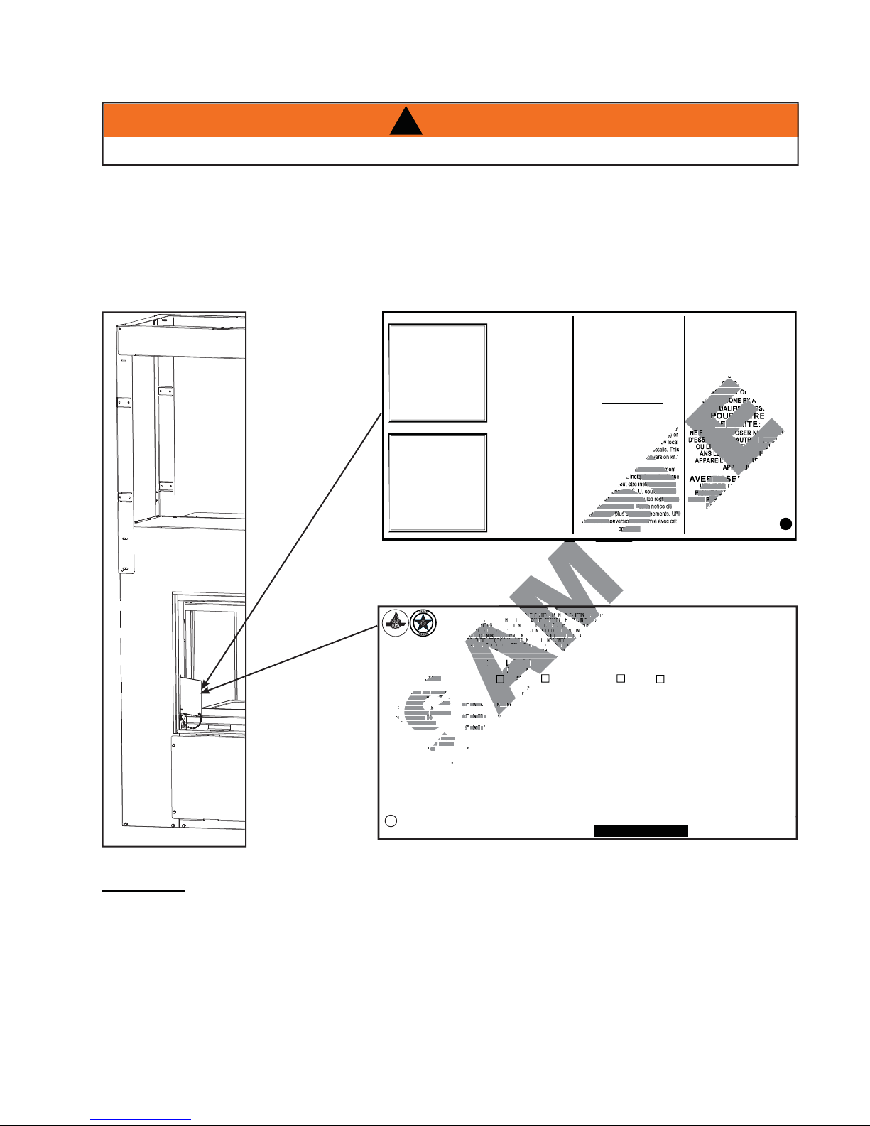
2.4 RATING PLATE / LIGHTING INSTRUCTION LOCATION
!
WARNING
ALLOW THE APPLIANCE TO COOL BEFORE PERFORMING ANY MAINTENANCE OR CLEANING.
Both the rating plate and lighting instructions are attached to a key chain and inserted in a mail slot on the left
side of the appliance (access side). It is recommended to remove the door prior to instruction removal. Using
your fi ngers or a tool such as a screw driver or pencil, gently pull both chains toward you. With the chain at the
bulb end of the slot, wiggle the rating plate out being careful not to tear the instructions as they pass through
the slot.
To replace, slide the instructions and the chain back through the slot and re-attach the door (if removed).
WARNI NG:
KEEP BURNER AND CONTROL
COMPARTMENT CLEAN. SEE
INSTALLATION AND OPERATING
INSTRUCTIONS MANUAL.
APPLIANCE NEEDS FRESH
AIR FOR SAFE OPERATION
AND MUST BE INSTALLED
WITH ADEQUATE PROVISIONS
FOR COMBUSTION
AND VENTILATION AIR.
GARDEZ LE BRULEUR ET LE
COMPARTIMENT DES
CONTROLES PROPRES.
CONSULTEZ LE MANUEL
D’INFORMATION ET
D’INSTALLATION. PAR
MESURE DE SECURITE.
CET APPAREIL DOIT
ETRE ALIMENTE EN AIR
FRAIS ET AVEC SUFFISANT
D’AIR COMBURANTET
DE VENTILATION.
CERTIFIED UNDER / HOMOLOGUE SELON LES NORMES:
VENTED GAS FIREPLACE.APPROVED FOR BEDROOM, BATHROOM AND BED-SITTING ROOM INSTALLATION.SUITABLE FOR MOBILE HOME INSTALLATION IF INSTALLEDIN ACCORDANCE WITH THE
CURRENT STANDARDCAN/CSA Z240MH SERIES GAS EQUIPPED MOBILE HOMES, IN CANADA OR IN THE UNITED STATESTHE MANUFACTURED HOME CONSTRUCTION AND SAFETY STAND ARD , T ITL E 24
CERTIFIED
CERTIFIED FOR / CERTIFIEE
POUR CANADA / USA
REFERENCE # 161746
NOT FOR USE WITH
CERTIFIED
UNDE
AU GAZ ET V
R / HOMOLO
GUE SELO
ENTILÉ
V
E
NTED
N LES NOR
GAS FIRE
CURRENT S
MES
PLACE HEA
: CSA 2
T
ANDARD
TER. A
.33
PART
b
PPROVE
-
C
328
2008
AN/
0
C
. WHEN
D F
REFERENCE
S
, ANSI Z21
A
OR BED
Z240MH
FOYER
THIS US
ROOM, B
SERIES G
DE
.88b
STANDARD
#
CHAUFFA
- 2008 VE
W/N 16131
A
TH
AS EQUIP
MAISON
ROOM AN
GE AU GAZ
IS NOT
NTED GAS
MOBILE SI
PED MO
D BED
APPLIC
A
VEC
NORME DE
BILE HO
-S
SON INSTA
ABLE US
ITT
É
FIREPLAC
ING ROO
VACUATION
MES, IN
SECU
E
LL
THE STANDA
M
C
ATION C
NOT FOR USE WITH
RELAT
INSTA
RITÉ ET
.
A
HOM
E HEATER / AP
NADA O
LLATION.
I
OLO
VE
O
D
N
RD FOR
E
AU CRITÈRE
FO
R
GUÉ POUR
CON
IN THE UNIT
RME AUX EX
SUI
S
FIRE SAFE
TRUCTION DE
SOLID F
T
PAREIL DE
ABL
INSTALL
DE
E
ED STATE
IGENCES DE
FOR M
M
ESURES
T
Y CRI
AT
UEL. FOR U
MAISONS M
OBILE HOM
ION
CHAUF
S THE MAN
TERIA
DANS UNE
DE SÉCURIT
WITH
LA N
MODEL NATURAL
FOR MAN
ORME CAN/
FAGE ALIMEN
ANUFA
E INSTALL
UFAC
GLASS DOORS
CHAMB
É CONTRE
SE
CTURÉES,
TUR
UFACTUR
ATION IF INS
E
CSA Z240MH S
RE À COUC
D
CERTIFIED WITH THIS
H
OME CONST
L'INCEND
ED HOME INST
TITRE 2
TÉ
TALLED IN AC
HER, UNE
4
É
IE POU
CFR, SECTI
RI
RUCTION
E DE
GAS /
ALLATION
UNIT
R LES INSTA
SALLE D
MAISON
CORDANCE
AND SAF
ON
GAZ NATURAL
ONLY.
328
S, SITES AND
S MOBILES
E BA
0. DANS L
LL
ETY STANDAR
IN ET
ATI
WITH T
ONS DANS LES
UN STUDIO.
ÉQUIPÉES
COMMUN
E CAS OU CE
HE
D, TITLE
AU G
ITIES, ANSI
APPROPR
MAISO
WARNING
T
TE NORM
24 CFR,
AZ, EN
NS MA
IÉ POUR INST
/ NFPA 50
LHD50NT
VIGUEU
E D'ÉTATS
NUFACTURÉS,
:
DO NOT AD
TO THE APPLI
IN CON
TACT WITH
THAN THA
T SUPPLIED BY TH
MANU
FAC
TURER
MINIMUM
CLEARANCE T
COMBUSTIBLE
TOP
FL
OOR
RECE
SSED DE
RECE
S
S
ED
DE
FRA
MING (NOT INCLUDING
FA
CE
MA
TERIAL)
SIDE
S
V
E
N
T
BA
CK
MAN
TLE
T
O
P, S
IDES & B
SEE OWNER
S MANUAL
* MAXIMUM H
ORIZONTAL
H
ORIZONTAL
E MAXIM
SEE OWNER'S INS
ELECT
MAD
WO
LF STEEL LTD. B
R AU CANADA OU AUX
1A.
ALLATI
-UN
IS N
D ANY MAT
LE
ON
E
S S
ANC
PEUT Ê
D
I
ANS UNE
T
MODEL PROP
E, WHICH WIL
E
S ET LE
ERIAL
T
R
0-4500FT (0
ÉTATS-UNIS
E APPLIQUÉE,
S COMM
L
C
OME
-1370M
THE
U
DE LA
N
SE RÉFÉR
AUTÉS, AN
F
L
)
AMES, OT
LHD50PT
ANE
30,000 BTU/H
ER A LA NORM
SI/NFPA 501A.
HER
ALTIT
U
UN COMB
DE / ÉLÉVATIO
E
W
ITH THE
3.5" WATER COLUMN/D'UNE C
APPLIAN
CE.
O
MATERIA
4.5" WATER
LS:
COLUMN/D'UN
0”
0”
7.0" WATER C
PTH ONE S
OLUMN/D'UN
IDE
D 23
PTH SEE
"
THRU 13.5”
THE APPLIANCE MUST BE VEN
NAPOLEON VENT KITS.
FOR VENTING S
0”
R
ESEAL
2"
IN
G
0”
15" *
ACK: PE
R
S
TAND O
FF SPAC
ERS FOR F
RAMING
EXTENSIO
N / L'EXTENSION
ALE: 2". S
EE INSTRUCTI
TRUCTION
MANU
ON MANUAL FO
AL FOR MIN
IMUM AN
RICAL
RA
TING: 115V 0.82
E IN CAN
AMP, 60
ADA / FAB
HZ
RIQUÉ AU CAN
ARRIE,
AD
A
ONTARI
O, CANADA
E
23,000 BTU/H
I
NP
USTIBLE SOLIDE N
UT / ALI
N
DOIT PAS ÊTRÉ UTILISÉ A
REDUCED INPUT /
MENTATIO
0-4500FT (0-1370M)
N
#38
ALIME
OLONNE D'EAU
CET APPARE
E
NTAT
30,000 BTU/H
ORIFIC
I
ON RÉDUITE
E /
INJECT
VEC
IL. UTILISER
LES PO
23,000 BTU/H
MANIFOL
EUR
E C
D
RTES VITRÉES
OLONNE D'EAU
P
R
ESSURE
P
AVEC
#53
R
ES
HOMOLOGUÉ
SION AU COLL
/
MINIMUM
10" WATER COL
ECTE
ES SEULEMENT
AVEC CETTE U
UR
SUPPLY PRE
E
C
P
OLONNE D'EAU
RESSION
UM
N/D'
S
UN
SURE /
D'ALIMEN
E
CO
NITÉ.
L
ONNE D'EAU
TATI
MA
11" WATER COLUM
XIMUM
ON M
AVERTISS
INIMALE
SU
P
PRE
PLY
SSI
P
N/D'UNE COLONNE D'EAU
RESS
EMENT:
O
CET AP
N D'A
URE /
LIMEN
PAREI
TED USING THE APPROPRIATE
N'AJOUTE
TATION MAX
L AUCUN M
ENTR
13" WATER COL
SEE
OWN
ER EN CON
Z PAS
IMALE
E
ATÉRIAU DE
RS I
PEC
A
UM
NSTALL
AUTRE QUE CELUI
IF
TACT AVEC LES F
N/ D'UN
IC
S
IS NEC
. PROPER
VANT
AT
E CO
ION MANUAL
L'AP
ESSARY AFTER SE
LONNE D
P
CET AP
AR
REINSTALLATION AND
EI
QUI EST F
LAMMES
L DOIT ÉV
'EA
PAREI
D
U
'
ÉVACUATION
L PAR LE F
ACUER SES GAZ EN UTILISANT L'E
OURNI AVEC
RVICIN
DÉG
AGEM
G
THE VENT-AI
ABRIC
P
D'INS
ROPRE A
ENTS MINIMAU
TALLATION DE PROPRIÉTAIRE
MATÉRIAUX C
A
NT.
N
R
INTAKE SYSTEM.
APOL
PRÉC
E
ON. RÉFÉRER AU MA
X DES
ISE.
DESS
OMBUSTI
NSE
I
L EST IMPORTANT DE BIEN R
US
MBL
RESCE
E
BLES:
MATE
P
PROF
OUR
L
LER
NUEL
R
L'
ONDEUR D'E
IALS
L'ÉVENT APRÈS AVOIR ASSURÉ LE MAINT
ÉVACU
SYSTÉME
0
. FOR FI
ATION
PLAN
ÉIN
NCASTR
NISHING M
DE
STALLER
CH
PRIS
ER
”
É
E D'AIR.
2
ATER
E
ÉVEN
T
IALS
T
5"
DESSUS, CO
CÔ
R GRE
I
E
TES
N DU
AT
0
”
ER EX
TÉS &
D MAX
SELON LE MANUE
MANTEA
T
ARRIÈR
E
I
2"
MU
NSIONS.
M VENT LE
E: SELON
U
0
*
L
ARRIÉRE
L DE PRO
'EXTENS
NGTHS
LES ESPACEU
.
ION HOR
”
PRIÉTAIR
PLUS GR
RS DE
IZONT
E POUR L
ANDES. RÉFÉRER
ALE MAXIMALE:
DÉGAGEMENT POUR LES
15" *
0
ES MATÉRIA
2". RÉF
UX DE
AU
”
MAN
FINITION.
ÉRER AU M
UEL D'IN
MATÉ
RIAUX D'OSSA
STAL
AN
UEL D
LATION
SERIAL NUMBER/NO. DE SÉRIE:
'INSTR
TURE
DE PRO
UCTION POUR DES
PRIÉT
AIRE.
EXTENS
IONS
LHD50
C
LASSIFIC
ATION: 115V
0.82AMP, 60HZ
W385-044
8
SOLID FUEL. FOR USE
WITH GLASS DOORS
CERTIFIED WITH THIS
UNIT ONLY.
WARNI NG
TO THEAPPLIANCE, WHICH WILL COME
IN CONTACT WITH THE FLAMES, OTHER
THAN THAT SUPPLIED BY THE
MANUFACTURER WITH THEAPPLIANCE.
MINIMUM CLEARANCE TO
COMBUSTIBLE MATERIALS:
TOP 0”
FLOOR 0”
RECESSED DEPTH ONE SIDED 23.75"
RECESSED DEPTH SEE THRU 13.5”
FRAMING (NOT INCLUDING
FACE M ATERIA L)
SIDES 0”
BACK 0”
VENT TOP 3”
VENT SIDES & BOTTOM 2”
VERTICAL VENT 1”
MANTLE 18” *
TOP, SIDES& BACK: PER STAND OFF SPACERS FOR FRAMING MATERIALS. FOR FINISHING MATERIALS
SEE OWNERS MANUAL
* MAXIMUM HORIZONTAL EXTENSION / L'EXTENSION
HORIZONTALE MAXIMALE: 2". SEE INSTRUCTION MANUAL FOR GREATER EXTENSIONS.
SEE OWNER'S INSTRUCTION MANUAL FOR MINIMUMAND MAXIMUM VENT LENGTHS.
CFR, PART 328 0. W HEN THIS US STANDARD ISN OT A PPL ICA BLE USE THE STANDARD FOR FIR E S AFE TY C RIT ERI A F OR M ANU FACT UR ED H OME INSTALLAT ION S, S ITE S AN D C OMMUNITIES, ANSI / NFPA
501A. FOYER DE CHAUFFAGEAU GAZ AVEC ÉVACUATION.HOMOLOGUÉ POUR INSTALLATION DANS UNE CHAMBRE À COUCHER, UNE SALLE DE BAIN ET UN STUDIO. APPROPRIÉ POURINSTALLATIONDANS
UNE MAISON MOBILE SI SON INSTALLATIONCONFORME AUX EXIGENCES DE LA NORME CAN/CSA Z240MH SÉRIE DE MAISONS MOBILES ÉQUIPÉESAU GAZ, EN VIGUEUR AU CANADAOUAUXÉTATS-UNIS
DE LA NORME DE SECURITÉ ET DE CONSTRUCTIONDE MAISONS MANUFACTURÉES, TITRE 24 CFR, SECTION 3280. DANS LE CAS OU CETTE NORME D'ÉTATS-UNIS NEP EUTÊ TREAPPLIQUÉE, SE RÉFÉRER
ALANORMERELATIVEAUCRITÈREDEMESURESDESÉCURITÉCONTREL'INCENDIEPOURLESINSTALLATIONSDANS LES MAISONS MANUFACTURÉS, LES SITES ET LES COMMUNAUTÉS, ANSI/NFPA 501A.
THIS APPLIANCE MUST BE INSTALLED IN ACCORDANCE WITH LOCAL CODES, IF ANY; IF NONE, FOLLOW THE CURRENT ANSI Z223.1, OR CSA B149, INSTALLATION CODES./INSTALLER L’APPAREIL SELON
LES CODES OU RÈGLEMENTS LOCAUX, OU EN L’ABSENCE DE TELS RÈGLEMENTS, SELON LES CODES D’INSTALLATION ANSI Z223.1 OU CSA-B149 EN VIGUER.
MODEL NATURAL GAS /
MOD
:
DO NOT ADDANY MATERIAL
COME
APPLIANCE
13.
ELECTRICAL RATING: 115V.60HZ. LESS THAN 12 AMPERES
WOLF STEEL LTD.
24 NAPOLEON ROAD, BARRIE, ON, L4M 4Y4 CANADA
IMPROPER INSTALLATION,
ADJUSTMENT, ALTERATION,
SERVICE OR MAINTENANCE
CAN CAUSE PROPERTY DAMAGE,
PERSONAL INJURY OR LOSS OF
LIFE. REFER TO OWNER’S
MANUAL. INSTALLATION AND
SERVICE MUST BE PERFORMED
BY A QUALIFIED INSTALLER,
SERVICE AGENCY OR THE
GAS SUPPLIER.
ATTE NTI ON:
UN INSTALLATION OU UNE
MODIFICATION INAPPROPRIEE
DU REGLAGE, DU SERVICE ET DE
L’ENTRETIEN POURRAIENT ETRE
LA CAUSE DE DOMMAGES A LA
PROPRIETE DE BLESSURES
CORPORELLES OU MEME LA
MORT. CONSULTER LE MANUEL
D’INFORMATION, L’INSTALLATION
ET LE SERVICE DOIVENT
ETRE EXECUTES PAR UN
INSTALLATEUR QUALIFIE POUR
LE AZ, UNE ENTREPRISE DE
SERVICE OU LE FOURNISSEUR
DE GAZ SEULEMENT.
R
A
A
GAS
LHD50N
LHD50N
0-4500FT (0-1370M)
30,000 BTU/H
20,000 BTU/H
A
CLHD50N CLHD50P
ALTITUDE /ÉLÉVATION
INPUT /ALIMENTATION
REDUCED INPUT/ ALIMENTATION RÉDUITE
MANIFOLD PRESSURE/
PRESSIONAU COLLECTEUR
MINIMUM SUPPLYPRESSURE /
PRESSION D'ALIMENTATION MINIMALE
MAXIMUM SUPPLYPRESSURE /
PRESSION D'ALIMENTATIONMAXIMALE
INTAKE SYSTEM.
R
GAZ NATURAL
AZ N
3.5" WATERCOLUMN/D'UNE COLONNE D'EAU
4.5" WATERCOLUMN/D'UNE COLONNE D'EAU
7.0" WATERCOLUMN/D'UNE COLONNE D'EAU
THE APPLIANCE MUST BE VENTED USING THEAPPROPRIATE
NAPOLEON VENT KITS. SEE OWNERS INSTALLATION MANUAL
FOR VENTING SPECIFICS. PROPER REINSTALLATIONAND
RESEALING IS NECESSARYAFTER SERVICING THE VENT-AIR
SERIAL NUMBER/NO. DE SÉRIE: LHD50
ANSI Z21.50 - 2009 CSA 2.22b - 2009 VENTED GAS FIREPLACE / FOYER AU GAZ VENTILÉ
CAUTION:
HOT WHILE OPERATING. DO NOT TOUCH.
KEEP CHILDREN, CLOTHING, FURNITURE,
GASOLINE OR OTHER FLAMMABLE VAPORS
AUTRES LIQUIDES QUI EMETTENT DES GAZ
“This appliance is only for use with the type(s)
avec les types de gaz indiqués sur la plaque
mobile installée à demeure si les règlements
l’utilisateur pour plus de renseignements. Une
AWAY.
AVERTISSEMENT:
L’APPAREIL EST CHAUD PENDANT SON
FONCTIONNEMENT. LES ENFANTS, LES
VETEMENTS, LES MEUBLES, L’ESSENCE ET
VOLATILS INFLAMMABLES DOIVENT
ETRE TENUS ELOIGNES DE L’APPAREIL.
of gas indicated on the rating plate and may
be installed in an aftermarket, permanently
located, manufactured home (USA only) or
mobile home, where not prohibited by local
codes. See owner’s manual for details. This
appliance is supplied with a conversion kit.”
«Cet appareil doit être utilisé uniquement
signalétique et peut être installé dans une
maison préfabriquée (É.-U. seulement) ou
locaux le permettent. Voir la notice de
trousse de conversion est fournie avec cet
appareil.»
R
MODEL PROPANE/
PROPANE MODÈLE
LHD50P
0-4500FT (0-1370M)
30,000 BTU/H
20,000 BTU/H
10" WATERCOLUMN/D'UNE COLONNE D'EAU
11" WATE R CO LUM N/D' UNE C OLO NNE D 'EAU
13" WATERCOLUMN/ D'UNE COLONNE D'EAU
L'APPAREIL DOIT ÉVACUER SES GAZ EN UTILISANT L'ENSEMBLE
D'ÉVACUATION PROPREA NAPOLEON. RÉFÉRER AU MANUEL
D'INSTALLATION DE PROPRIÉTAIRE POUR L'ÉVACUATION
PRÉCISE. IL EST IMPORTANT DE BIEN RÉINSTALLER ET
RESCELLER L'ÉVENT APRÈSAVOIR ASSURÉ LE MAINTIEN DU
SYSTÉME DE PRISE D'AIR.
DESSUS,COTÉS & ARRIÈRE: SELON LES ESPACEURS DE
DÉGAGEMENTPOUR LESMATÉRIAUXD'OSSATURE SELON LA
MANUEL DE PROPRIÉTAIREPOURLES MATÉRIAUXDE FINITION.
*L'EXTENSIONHORIZONTALEMAXIMALE: 2".RÉFÉRERAU
MANUELD'INSTRUCTION POUR DES EXTENSIONS PLUS GRANDES.
RÉFÉRERAU MANUEL D'INSTALLATION DE PROPRIÉTAIRE.
FOR YOUR SAFETY:
DO NOT STORE OR USE GASOLINE
OR OTHER FLAMMABLE VAPORS
AND LIQUIDS IN VICINITY OF THIS
OR ANY OTHER APPLIANCE.
CAUTION: DO NOT OPERATE
THE FIREPLACE WITH THE GLASS
REMOVED, CRACKED OR BROKEN.
REPLACEMENT OF THE GLASS
SHOULD BE DONE BY A LICENSED
OR QUALIFIED PERSON.
POUR VOTRE
SECURITE:
NE PAS ENTREPOSER NI UTILISER
D’ESSENCE NI D’AUTRES VAPEURS
OU LIQUIDES INFLAMMABLES
ANS LE VOISINAGE DE CET
APPAREIL OU DE TOUT AUTRE
APPAREIL.
AVE RTI SSE MEN T: NE PAS
UTILISER L’APPAREIL SI LE
PANNEAU FRONTAL EN VERRE
N’EST PAS EN PLACE, EST CRAQUÉ
OU BRISÉ. CONFIEZ LE
REMPLACEMENT DU
PANNEAU À UN
TECHNICIEN
AGRÉÉ.
UN COMBUSTIBLE SOLIDE NE
DOIT PAS ÊTRÉ UTILISÉ AVEC
CET APPAREIL. UTILISERAVEC
LES PORTES VITRÉES
HOMOLOGUÉES SEULEMENT
AVEC CETTE UNITÉ.
AVERTISSEMENT:
CET APPAREILAUCUN MATÉRIAU DEVANT
ENTRER EN CONTACTAVEC LES FLAMMES
AUTRE QUE CELUI QUI EST FOURNIAVEC
CET APPAREILPAR LE FABRICANT.
DÉGAGEMENTS MINIMAUX DES
MATÉRIAUX COMBUSTIBLES:
DESSUS 0"
PLANCHER 0"
PROFONDEUR DE L’ENCLAVEFACE
UNIQUE 23.75"
PROFONDEUR DE L’ENCLAVE BINAIRE 13.5"
OSSATURE (MATÉRIAU DE FAÇADE NON
COMPRIS)
CÔTÉS 0"
ARRIÈRE 0"
DESSUS DU CONDUIT D’ÉVENT 3"
CÔTÉS ET DESSOUS DU CONDUIT
D’ÉVENT 2"
CONDUIT D’ÉVENT VERTICAL 1"
TABLETTE 18"
SPÉCIFICATIONS ÉLECTRIQUES : 115V,
60 HZ. MOINS DE 12 AMPÈRES.
N'AJOUTEZ PASA
W385-0448 / E
INSTALLER: It is your responsibility to check off the appropriate box on the rating plate according to
the model, venting and gas type of the appliance.
This illustration is for reference only. Refer to the rating plate on the appliance for accurate information.
W415-0745 / D / 11.30.11
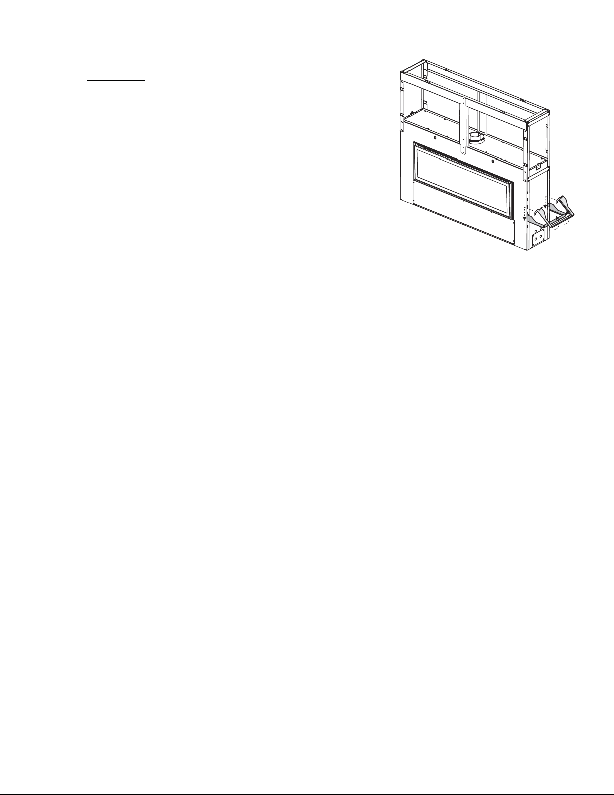
2.5 SHIPPING HANDLES
IMPORTANT
This appliance fully dressed weighs 300 lbs.
A. Lift up and secure the framing kit, see “STEEL STUD
FRAMING KIT” section for instructions.
B. Insert the shipping handles (not supplied) by placing the tabs
in the desired slots on both sides of the appliance and lifting
upwards to secure in place.
C. Remove handles once the appliance is in its preferred
location. Use shipping brackets to secure base of appliance.
9
W415-0745 / D / 11.30.11

10
3.0 VENTING
RISK OF FIRE, MAINTAIN SPECIFIED AIR SPACE CLEARANCES TO VENT PIPE AND APPLIANCE.
IF VENTING IS INCLUDED WITH SPACERS THE VENT SYSTEM MUST BE SUPPORTED EVERY 3 FEET
FOR BOTH VERTICAL AND HORIZONTAL RUNS. USE SUPPORTS OR EQUIVALENT
NON-COMBUSTIBLE STRAPPING TO MAINTAIN THE REQUIRED CLEARANCE FROM
COMBUSTIBLES. USE WOLF STEEL LTD. SUPPORT RING ASSEMBLY W010-0370 OR EQUIVALENT
NON-COMBUSTIBLE STRAPPING TO MAINTAIN THE MINIMUM CLEARANCE TO COMBUSTIBLES
FOR BOTH VERTICAL AND HORIZONTAL RUNS. SPACERS ARE ATTACHED TO THE INNER PIPE AT
PREDETERMINED INTERVALS TO MAINTAIN AN EVEN AIR GAP TO THE OUTER PIPE. THIS GAP IS
REQUIRED FOR SAFE OPERATION. A SPACER IS REQUIRED AT THE START, MIDDLE AND END OF
EACH ELBOW TO ENSURE THIS GAP IS MAINTAINED. THESE SPACERS MUST NOT BE REMOVED.
THIS APPLIANCE USES A 5” EXHAUST / 8” AIR INTAKE VENT PIPE SYSTEM.
For safe and proper operation of the appliance follow the venting instruction exactly. Deviation from the
minimum vertical vent length can create diffi culty in burner start-up and/or carboning. Under extreme vent
confi gurations, allow several minutes (5-15) for the fl ame to stabilize after ignition. Provide a means for
visually checking the vent connection to the appliance after the appliance is installed. Use a fi restop, vent pipe
shield or attic insulation shield when penetrating interior walls, fl oor or ceiling.
NOTE: If for any reason the vent air intake system is disassembled; reinstall per the instructions
provided for the initial installation.
!
WARNING
Refer to the section applicable to your installation.
7.2A
3.1 VENTING LENGTHS AND COMPONENTS FOR DIRECT VENT INSTALLATIONS
Use only Wolf Steel, Simpson Dura-Vent, Selkirk Direct Temp, American Metal Amerivent or Metal-Fab
venting components. Minimum and maximum vent lengths, for both horizontal and vertical installations, and
air terminal locations for either system are set out in this manual and must be adhered to. For Simpson DuraVent, Selkirk Direct Temp, American Metal Amerivent and Metal-Fab follow the installation procedure provided
with the venting components.
A starter adaptor must be used with the following vent systems and may be purchased from the
corresponding supplier:
PART 5”/8” SUPPLIER WEBSITE
Duravent W175-0170 Wolf Steel www.duravent.com
Amerivent 5DSC-N2 American Metal www.americanmetalproducts.com
Direct Temp 5DT-AA Selkirk www.selkirkcorp.com
SuperSeal 5DDA Metal-Fab www.mtlfab.com
For Simpson Dura-Vent, Selkirk Direct Temp, American Metal Amerivent and Metal-Fab follow the installation
procedure found on the website for your venting supplier.
For vent systems that provide seals on the inner exhaust fl ue, only the outer air intake joints must be sealed using a
red high temperature silicone (RTV). This same sealant may be used on both the inner exhaust and outer intake vent
pipe joints of all other approved vent systems except for the exhaust vent pipe connection to the appliance fl ue collar
which must be sealed using the black high temperature sealant Mill Pac.
When using Wolf Steel venting components, use only approved Wolf Steel rigid / fl exible components with the following
termination kits: wall terminal kit GD422-1, GD422R-1, or 1/12 to 7/12 pitch roof terminal kit GD410, 8/12 to 12/12 roof
terminal kit GD411, fl at roof terminal kit GD412 or periscope kit GD401 (for wall penetration below grade). With fl exible
venting, in conjunction with the various terminations, use either the 5 foot vent kit GD420 or the 10 foot vent kit GD430.
W415-0745 / D / 11.30.11
For optimum fl ame appearance and appliance performance, keep the vent length and number of elbows to a
minimum.
The air terminal must remain unobstructed at all times. Examine the air terminal at least once a year to verify
that it is unobstructed and undamaged.
Rigid and fl exible venting systems must not be combined. Different venting manufacturer components must
not be combined.
These vent kits allow for either horizontal or vertical venting of the appliance. The maximum allowable horizontal run
is 20 feet. The maximum allowable vertical vent length is 40 feet. The maximum number of vent connections is two
horizontally or three vertically (excluding the appliance and the air terminal connections) when using fl exible venting.
Horizontal runs may have a 0” rise per foot however for optimum performance it is recommended that all horizontal
runs have a minimum 1/4” rise per foot using fl exible venting. For safe and proper operation of the appliance, follow
the venting instructions exactly.
A terminal shall not terminate directly above a sidewalk or paved driveway which is located between two single family
dwellings and serves both dwellings. Local codes or regulations may require different clearances.
Do not allow the inside liner to bunch up on horizontal or vertical runs and elbows. Keep it pulled tight. A 1¼” air gap
all around between the inner liner and outer liner is required for safe operation.
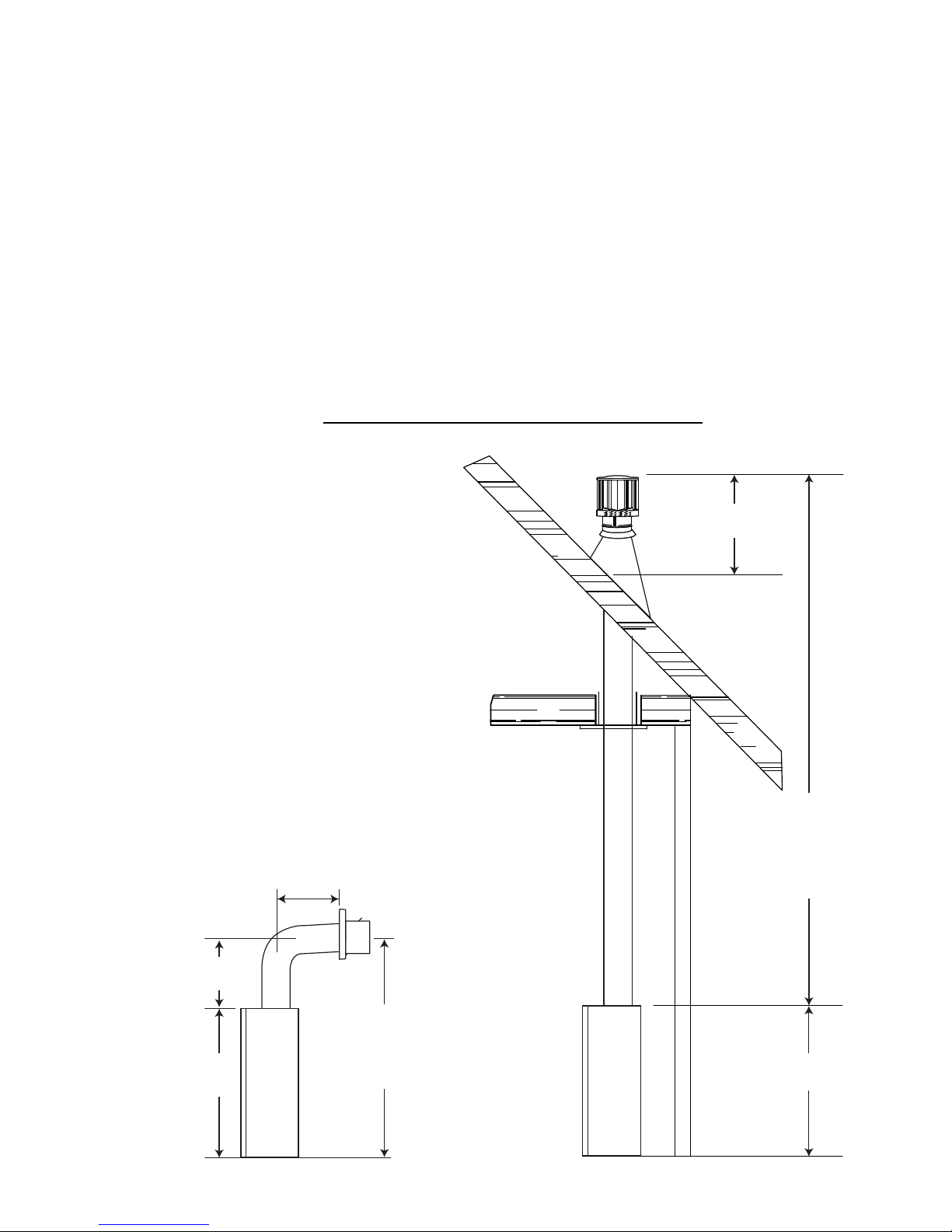
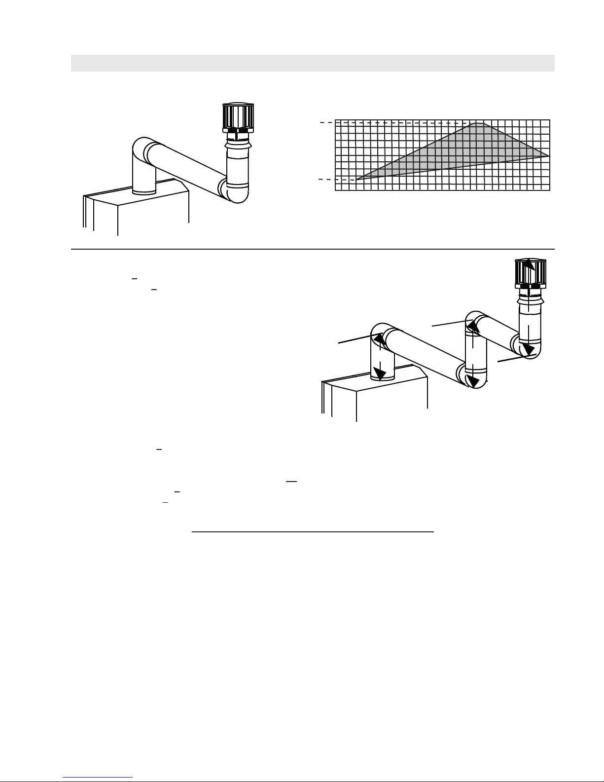
3.2 TYPICAL VENT INSTALLATIONS
11
8.3
24”
MAXIMUM
16” MINIMUM
40 FEET
MAXIMUM
3 FEET
MINIMUM
15” MINIMUM
36”
* See “VENTING” section.
51”
MINIMUM
PLUS
RISE*
36”
W415-0745 / D / 11.30.11
12
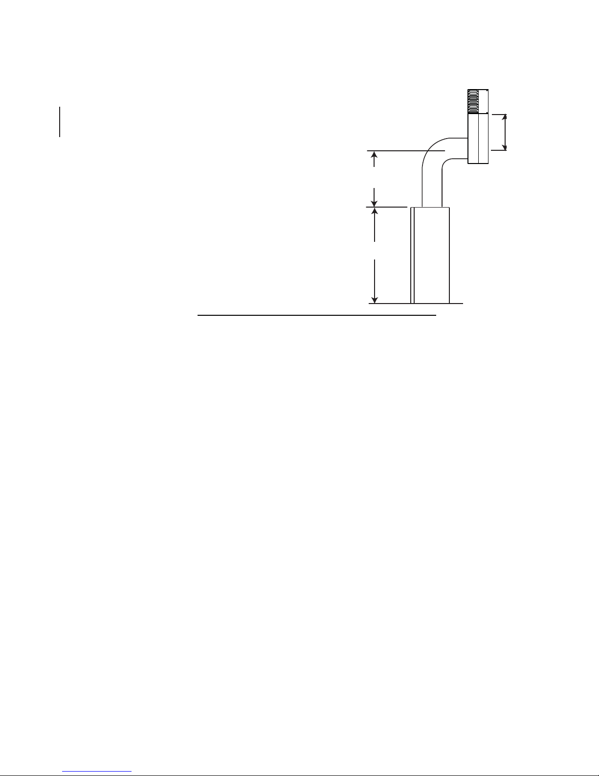
3.3 SPECIAL VENT INSTALLATION
3.3.1 PERISCOPE TERMINATION
Use the periscope kit to locate the air termination above grade. The periscope must
be installed so that when fi nal grading is completed, the bottom air slot is located a
minimum 12” above grade. The maximum allowable vent length is 10’ for a
fi replace and 8’ for a stove.
12”
MIN TO
GRADE
30” MIN
36”
9.1A
W415-0745 / D / 11.30.11
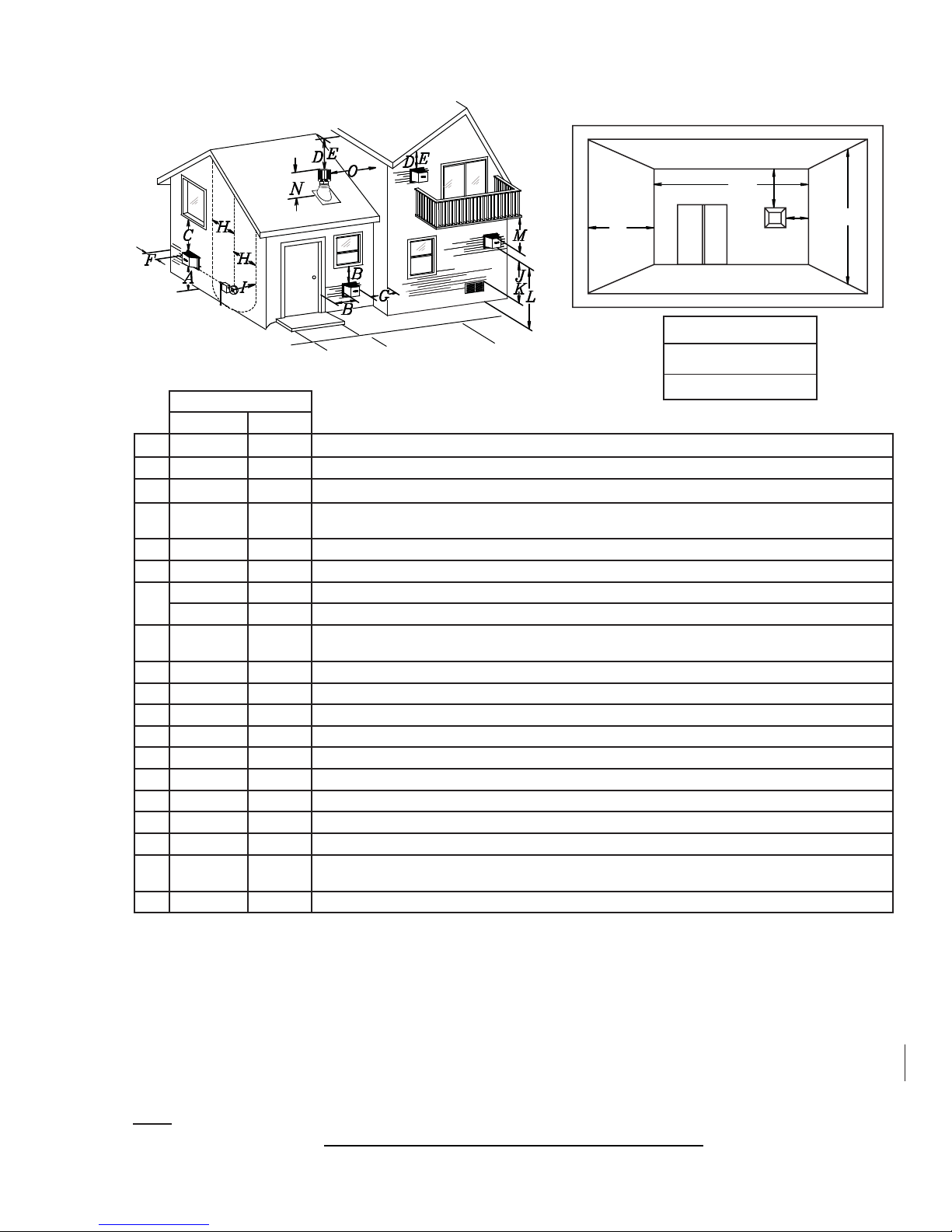
3.4 MINIMUM AIR TERMINAL LOCATION CLEARANCES
COVERED BALCONY APPLICATIONS ††*
R
13
Q
S
G
P
Q
R
R
INSTALLATIONS
MIN
MAX
MAX
= 3 feet
= 2 x
Q
feet
ACTUAL
CANADA U.S.A.
A 12” 12” Clearance above grade, veranda porch, deck or balcony.
B 12”
9”
Clearance to windows or doors that open.
C 12” * 12” * Clearance to permanently closed windows.
D 18” ** 18” **
Vertical clearance to ventilated soffi ts located above the terminal within a horizontal distance of 2’ from
the center line of the terminal.
E 12” ** 12” ** Clearance to unventilated soffi t.
F 0” 0” Clearance to an outside corner wall.
0” *** 0” *** Clearance to an inside non-combustible corner wall or protruding non-combustible obstructions (chimney, etc.).
G
2” *** 2” *** Clearance to an inside combustible corner wall or protruding combustible obstructions (vent chase, etc.).
H 3’ 3’ ****
Clearance to each side of the center line extended above the meter / regulator assembly to a maximum
vertical distance of 15’.
I 3’ 3’ **** Clearance to a service regulator vent outlet.
J 12” 9” Clearance to a non-mechanical air supply inlet to the building or a combustion air inlet to any other appliance.
K 6’ 3’ † Clearance to a mechanical air supply inlet.
L 7’ ‡ 7’ **** Clearance above a paved sidewalk or paved driveway located on public property.
M 12” †† 12” **** Clearance under a veranda, porch or deck.
N 16” 16” Clearance above the roof.
O 2’ †* 2’ †* Clearance from an adjacent wall including neighbouring buildings.
P 8’ 8’ Roof must be non-combustible without openings.
Q 3’ 3’ See chart for wider wall dimensions.
R 6’ 6’
See chart for deeper wall dimensions. The terminal shall not be installed on any wall that has an opening between the terminal and the open side of the structure.
S 12” 12” Clearance under a covered balcony
The terminal shall not be located less than 6 feet under a window that opens on a horizontal plane in a structure with three walls and a roof.
* Recommended to prevent condensation on windows and thermal breakage
** It is recommended to use a heat shield and to maximize the distance to vinyl clad soffi ts.
*** The periscope requires a minimum 18 inches clearance from an inside corner.
**** This is a recommended distance. For additional requirements check local codes.
†3 feet above if within 10 feet horizontally.
‡A vent shall not terminate where it may cause hazardous frost or ice accumulations on adjacent property surfaces.
†† Permitted only if the veranda, porch, or deck is fully open on a minimum of two sides beneath the fl oor.
†* Recommended to prevent recirculation of exhaust products. For additional requirements check local codes.
††* Permitted only if the balcony is fully open on a minimum of one side.
NOTE: Clearances are in accordance with local installation codes and the requirements of the gas supplier.
12.1C
W415-0745 / D / 11.30.11
14
3.5 VENT APPLICATION FLOW CHART
TOP EXIT
Horizontal Termination
Vertical rise is equal
to or greater than
the horizontal run
Horizontal run +
vertical rise to
maximum of 40 feet
3.6 DEFINITIONS
For the following symbols used in the venting calculations and examples are:
> - greater than
> - equal to or greater than
< - less than
< - equal to or less than
HT - total of both horizontal vent lengths (Hr) and offsets (Ho) in feet
HR - combined horizontal vent lengths in feet
HO - offset factor: .03 (total degrees of offset - 90°*) in feet
VT - combined vertical vent lengths in feet
Vertical rise is less
than horizontal run
Horizontal run +
vertical rise to
maximum of 24.75
feet
4.2 times the
vertical rise equal to
or greater than the
horizontal run
Vertical Termination
Vertical rise is equal
to or greater than
the horizontal run
Horizontal run +
vertical rise to
maximum of 40 feet
Vertical rise is less
than horizontal run
Horizontal run +
vertical rise to
maximum of 40 feet
3 times the vertical
rise equal to or
greater than the
horizontal run
13.1
14.1
3.7 ELBOW VENT LENGTH VALUES
FEET INCHES
1° 0.03 0.5
15° 0.45 6.0
30° 0.9 11.0
45° 1.35 16.0
90°* 2.7 32.0
* The fi rst 90° offset has a zero value and is shown in the formula as - 90°
W415-0745 / D / 11.30.11
15.1
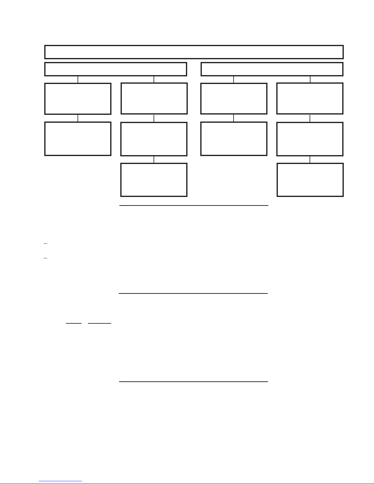
3.8 HORIZONTAL TERMINATION
15
(HT) < (VT)
Simple venting confi guration (only one 90° elbow)
See graph to determine the required vertical
rise VT for the required horizontal run HT.
40
39
30
REQUIRED
VERTICAL
20
RISE IN
FEET VT
10
0
2.5 5 7.5 10 12.5 15
HORIZONTAL VENT RUN PLUS OFFSET IN
FEET H
T
The shaded area within the lines represents
acceptable values for HT and V
For vent confi gurations requiring more than one 90° elbow, the following formulas apply:
Formula 1: HT < V
T
Formula 2: HT + VT < 40 feet
Example:
V1 = 3 FT
90°
V2 = 8 FT
VT = V1 + V2= 3 FT + 8 FT = 11 FT
V
H1 = 2.5 FT
2
H2 = 2 FT
HR = H1 + H2 = 2.5 + 2 = 4.5 FT
HO = .03 (three 90° elbows - 90°) = .03 (270° - 90°) = 5.4 FT
HT = HR + HO = 4.5 + 5.4 = 9.9 FT
HT + VT = 9.9 + 11 = 20.9 FT
90°
90°
H
1
17.5 20
T
H
2
Formula 1: HT < V
T
9.9 < 11
Formula 2: HT + VT < 40 FT
20.9 < 40
Since both formulas are met, this vent confi guration is acceptable.
V
1
16.1A
W415-0745 / D / 11.30.11

16
V
V
V
V
(HT) > (VT)
Simple venting configuration (only one 90° elbow)
REQUIRED
See graph to determine the required vertical rise VT for the
required horizontal run H
150
147”
100
.
T
VERTICAL
RISE IN
INCHES V
T
57”
50
15”
0
515
2’
10
12.5’
19.5’
20
HORIZONTAL VENT RUN PLUS OFFSET IN FEET H
T
The shaded area within the lines represents acceptable
values for HT and VT
For vent configurations requiring more than one 90° elbow, the following formulas apply:
< 4.2 V
Formula 1:
Formula 2: HT + V
H
T
T
< 24.75 feet
T
90°
H
1
H
2
Example:
= VT = 6 FT
1
H
= 3 FT
1
H
= 5 FT
2
H
= H
+ H
R
H
= .03 (two 90° elbows - 90°) = .03 (180° - 90°) = 2.7 FT
O
H
= H
T
H
+ V
T
= 3 + 5 = 8 FT
1
2
+ H
= 8 + 2.7 = 10.7 FT
R
O
= 10.7 + 6 = 16.7 FT
T
V
1
90°
Formula 1: HT < 4.2 V
4.2 V
10.7 < 25.2
Formula 2: HT + V
16.7 < 24.75
Since both formulas are met, this vent configuration is acceptable.
Example:
= 4 FT
1
= 1.5 FT
2
= V
+ V
T
H
= 2 FT
1
H
= 1 FT
2
H
= 1 FT
3
H
= 1.5 FT
4
H
= H
R
H
= .03 (four 90° elbows - 90°) = .03 (360° - 90°) = 8.1 FT
O
H
= H
T
H
+ V
T
= 4 + 1.5 = 5.5 FT
1
2
+ H2 + H
1
+ H
R
= 13.6 + 5.5 = 19.1 FT
T
+ H4 = 2 + 1 + 1 + 1.5 = 5.5 FT
3
= 5.5 + 8.1 = 13.6 FT
O
Formula 1: HT < 4.2 V
4.2 V
13.6 < 23.1
Formula 2: HT + V
19.1 < 24.75
T
= 4.2 x 6 = 25.2 FT
T
< 24.75 FT
T
T
= 4.2 x 5.5 = 23.1 FT
T
< 24.75 FT
T
90°
90°
90°
H
1
90°
V
1
V
2
H
H
2
3
H
4
Since both formulas are met, this vent configuration is acceptable.
16.4
W415-0745 / D / 11.30.11
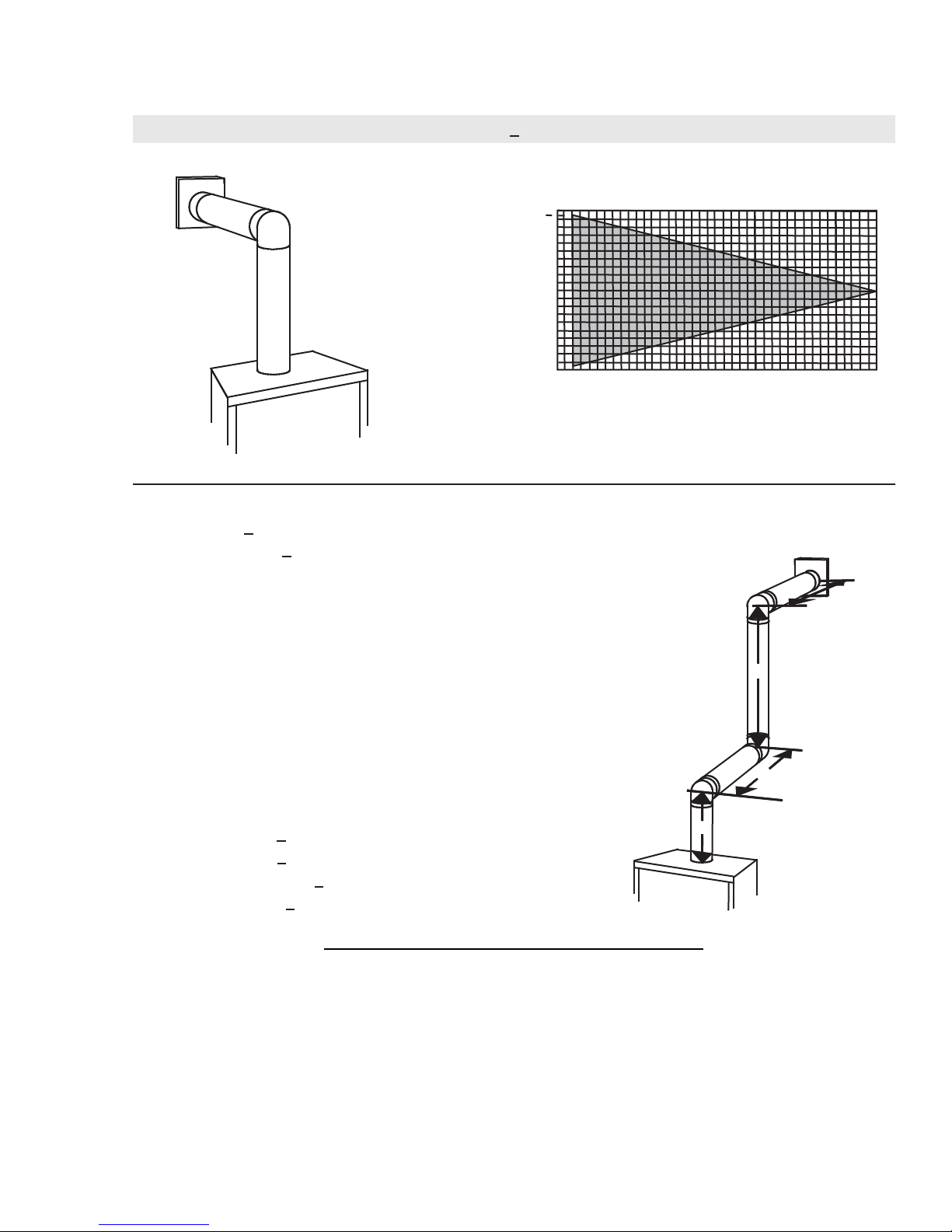
3.9 VERTICAL TERMINATION
17
(HT) < (VT)
Simple venting configurations.
See graph to determine the required vertical rise V
required horizontal run HT.
40
30
REQUIRED
VERTICAL
20
RISE IN
FEET V
T
10
3
0
5101520
HORIZONTAL VENT RUN PLUS OFFSET IN FEET H
The shaded area within the lines represents acceptable
values for HT and VT
For vent configurations requiring one or more 90° elbows the following formulas apply:
Formula 1: H
Formula 2: HT + V
< V
T
T
< 40 feet
T
for the
T
T
Example:
V
= 5 FT
1
V
= 6 FT
2
V
= 10 FT
3
V
= V
+ V2 + V3 = 5 + 6 + 10 = 21 FT
T
1
H
= 8 FT
1
H
= 2.5 FT
2
H
= H
+ H
R
H
= .03 (four 90° elbows - 90°)
O
= .03 (360° - 90°) = 8.1 FT
H
= H
T
H
+ V
T
Formula 1: HT < V
18.6 < 21
Formula 2: HT + V
39.6 < 40
= 8 + 2.5 = 10.5 FT
1
2
+ H
= 10.5 + 8.1 = 18.6 FT
R
O
= 18.6 + 21 = 39.6 FT
T
T
< 40 FT
T
Since both formulas are met, this vent configuration is acceptable.
90°
V
3
90°
H
2
V
H
1
V
1
2
90°
90°
18.1
W415-0745 / D / 11.30.11
18
(HT) > (VT)
Simple venting configurations.
See graph to determine the required vertical rise V
required horizontal run H
20
19
REQUIRED
VERTICAL
RISE IN
FEET V
10
T
3
0
5101520
HORIZONTAL VENT RUN PLUS OFFSET IN FEET H
The shaded area within the lines represents acceptable
values for HT and VT
For vent configurations requiring more than two 90° elbows the following formulas apply:
Formula 1: H
Formula 2: HT + V
< 3V
T
T
< 40 feet
T
Example:
V
= 2 FT
1
V
= 1 FT
2
V
= 1.5 FT
3
V
= V
+ V2 + V3 = 2 + 1 + 1.5 = 4.5 FT
T
1
H
= 6 FT
1
H
= 2 FT
2
H
= H
+ H
R
H
= .03 (four 90° elbows - 90°)
O
= .03 (360° - 90°) = 8.1 FT
H
= H
T
H
+ V
T
= 6 + 2 = 8 FT
1
2
+ H
= 8 + 8.1 = 16.1 FT
R
O
= 16.1 + 4.5 = 20.6 FT
T
90°
H
V
1
1
90°
for the
.
T
H
V
2
T
25 30
V
2
T
3
90°
90°
Formula 1: HT < 3V
3V
16.1 > 13.5
T
= 3 x 4.5 = 13.5 FT
T
Since this formula is not met, this vent configuration is unacceptable.
Formula 2: HT + VT < 40 feet
20.6 < 40
Since only formula 2 is met, this vent configuration is unacceptable and a new appliance location or vent configuration will
need to be established to satisfy both formulas.
18.1_2A
W415-0745 / D / 11.30.11
4.0 INSTALLATION
FOR SAFE AND PROPER OPERATION OF THE APPLIANCE, FOLLOW THE VENTING INSTRUCTIONS
ALL INNER EXHAUST AND OUTER INTAKE VENT PIPE JOINTS MAY BE SEALED USING EITHER RED
RTV HIGH TEMP SILICONE SEALANT W573-0002 (NOT SUPPLIED) OR BLACK HIGH TEMP MILL PAC
W573-0007 (NOT SUPPLIED) WITH THE EXCEPTION OF THE APPLIANCE EXHAUST FLUE COLLAR
WHICH MUST BE SEALED USING MILL PAC.
IF USING PIPE CLAMPS TO CONNECT VENT COMPONENTS, 3 SCREWS MUST ALSO BE USED TO
ENSURE THE CONNECTION CANNOT SLIP OFF.
RISK OF FIRE, EXPLOSION OR ASPHYXIATION. IMPROPER SUPPORT OF THE ENTIRE VENTING
SYSTEM MAY ALLOW VENT TO SAG AND SEPARATE. USE VENT RUN SUPPORTS AND CONNECT
VENT SECTIONS PER INSTALLATION INSTRUCTIONS.
RISK OF FIRE, DO NOT ALLOW LOOSE MATERIALS OR INSULATION TO TOUCH THE VENT PIPE.
REMOVE INSULATION TO ALLOW FOR THE INSTALLATION OF THE ATTIC SHIELD AND TO
MAINTAIN CLEARANCES TO COMBUSTIBLES.
!
WARNING
EXACTLY.
DO NOT CLAMP THE FLEXIBLE VENT PIPE.
19
4.1 WALL AND CEILING PROTECTION
!
DO NOT FILL THE SPACE BETWEEN THE VENT PIPE AND ENCLOSURE WITH ANY TYPE OF
MATERIAL. DO NOT PACK INSULATION OR COMBUSTIBLES BETWEEN CEILING FIRESTOPS.
ALWAYS MAINTAIN SPECIFIED CLEARANCES AROUND VENTING AND FIRESTOP SYSTEMS.
INSTALL WALL SHIELDS AND FIRESTOPS AS SPECIFIED. FAILURE TO KEEP INSULATION OR
OTHER MATERIALS AWAY FROM VENT PIPE MAY CAUSE FIRE.
For optimum performance it is recommended that all horizontal runs have a minimum of 1/4” rise per foot using
fl exible venting. For safe and proper operation of the appliance, follow the venting instructions exactly.
68.2A
WARNING
70.1
W415-0745 / D / 11.30.11
20
A
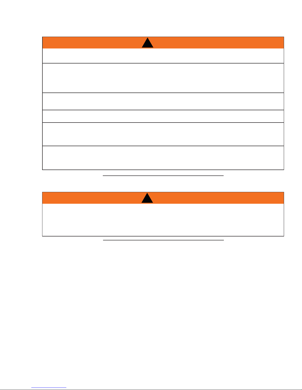
4.1.1 HORIZONTAL INSTALLATION
THE FIRESTOP ASSEMBLY MUST BE INSTALLED WITH THE VENT SHIELD TO THE TOP.
TERMINALS MUST NOT BE RECESSED INTO A WALL OR SIDING MORE THAN THE DEPTH OF THE
RETURN FLANGE OF THE MOUNTING PLATE.
This application occurs when venting through an exterior wall.
Having determined the correct height for the air terminal
location, cut and frame a hole in the exterior wall as
illustrated to accommodate the fi restop assembly.
Dry fi t the fi restop assembly before proceeding to
ensure the brackets on the rear surface fi t to the
inside surface of the horizontal framing.
The length of the vent shield may be cut shorter
for combustible walls that are less than 8 1/2” thick
but the vent shield must extend the full depth of the
combustible wall.
. Apply a bead of caulking (not supplied) around the corner edge of
the inside surface of the fi restop assembly, fi t the fi restop
assembly to the hole and secure using the 4 screws (supplied in your
manual baggie).
!
WARNING
CAULKING
FIRESTOP
SPACER
VENT
SHIELD
DETERMINE
THE
CORRECT
HEIGHT
FINISHING
MATERIAL
B. Once the vent pipe is installed in its fi nal position, apply high temperature sealant W573-0007 (not
supplied) between the pipe and the fi restop.
20.2
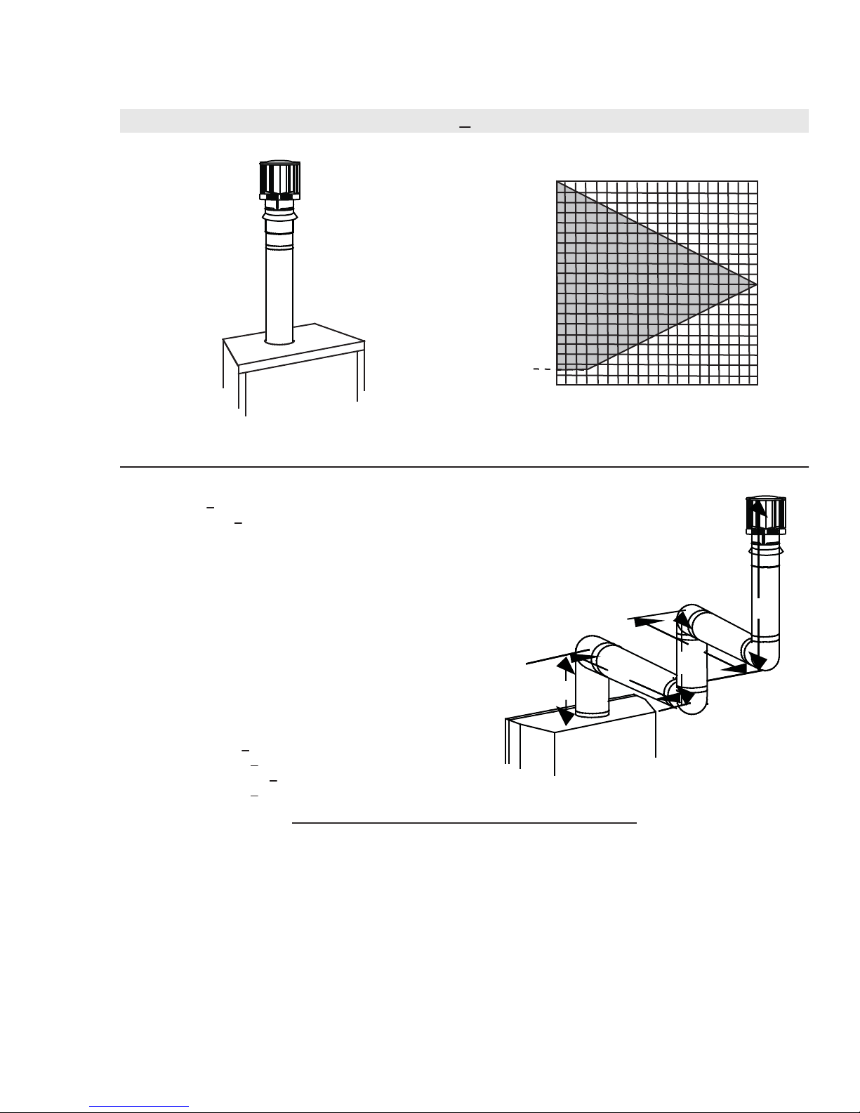
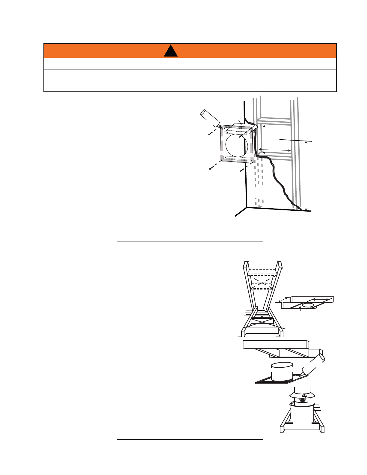
4.1.2 VERTICAL INSTALLATION
This application occurs when venting through a roof. Installation kits for
various roof pitches are available from your authorized dealer / distributor. See
accessories to order specifi c kits required.
A. Determine the air terminal location, cut and frame a square opening as
illustrated in the ceiling and the roof to provide the minimum 1“ clearance
between the vent pipe and any combustible material. Try to center the vent
pipe location midway between two joists to prevent having to cut them. Use
a plumb bob to line up the center of the openings. A vent pipe shield will
prevent any materials such as insulation, from fi lling up the 1” air space
around the pipe. Nail headers between the joist for extra support.
B. Apply a bead of caulking (not supplied) to the framework or to the Wolf
Steel vent pipe shield plate or equivalent (in the case of a fi nished ceiling),
and secure over the opening in the ceiling. A fi restop must be placed on the
bottom of each framed opening in a roof or ceiling that the venting system passes
through. Apply a bead of caulking all around and place a fi restop spacer over
the vent shield to restrict cold air from being drawn into the room or around the
fi replace. Ensure that both spacer and shield maintain the required clearance to
combustibles. Once the vent pipe is installed in its fi nal position, apply sealant
between the pipe and the fi restop assembly.
C. In the attic, slide the vent pipe collar down to cover up the open end of the shield and
tighten. This will prevent any materials, such as insulation, from fi lling up the 1” air space
around the pipe.
10 3/4”
FIRESTOP
UNDERSIDE OF
JOIST
VENT PIPE
SHIELD
VENT
PIPE
SHIELD
21.1
10 3/4”
CAULKING
VENT
PIPE
COLLAR
W415-0745 / D / 11.30.11
 Loading...