

Page 1
NATURAL GAS MODELS:
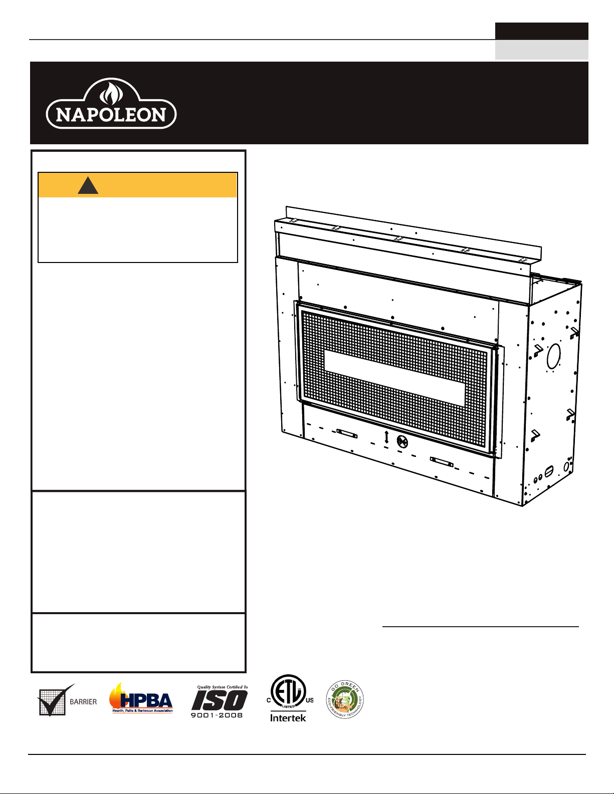
SAFETY BARRIER
ÉCRAN DE PROTECTION
L38N / L50N / L38N2 / L50N2
ADD PRODUCT CODE HERE (TRADE GOTHIC LT STD FONT)
ENGLISH
PROPANE GAS MODELS:
L38P / L50P / L38P2 / L50P2
INSTALLATION MANUAL
SAFETY INFORMATION
!
WARNING
FIRE OR EXPLOSION HAZARD
Failure to follow safety warnings exactly
could result in serious injury, death, or
property damage.
- Do not store or use gasoline or other
fl ammable vapors and liquids in the vicinity of
this or any other appliance.
- WHAT TO DO IF YOU SMELL GAS:
• Do not try to light any appliance.
• Do not touch any electrical switch; do not
use any phone in your building.
• Immediately call your gas supplier from a
neighbour’s phone. Follow the gas
supplier’s instructions.
• If you cannot reach your gas supplier, call
the fi re department.
FRENCH
PG. 67
ADD MANUAL TITLE
PRODUCT NAME™
ADD PRODUCT IMAGE
Acies™ Series
(L38 illustrated)
ADD ____ ILLUSTRATED
- Installation and service must be
performed by a qualifi ed installer, service
agency, or the supplier.
This appliance may be installed in an aftermarket,
permanently located, manufactured home (USA
only) or mobile home, where not prohibited by
local codes.
This appliance is only for use with the type of gas
indicated on the rating plate. This appliance is
not convertible for use with other gases, unless
a certifi ed kit is used.
Leave this manual with the appliance
Retain this manual for future reference
INSTALLER:
CONSUMER:
Wolf Steel Ltd., 24 Napoleon Rd., Barrie, ON, L4M 0G8 Canada / 103 Miller Drive, Crittenden, Kentucky, USA, 41030
Phone 1 (866) 820-8686 • www.napoleonfi replaces.com • hearth@napoleonproducts.com
This appliance is NOT
compatible with Dynamic Heat
FOR INDOOR USE ONLY
CERTIFIED TO THE CANADIAN AND AMERICAN NATIONAL STANDARDS:
CSA 2.22 AND ANSI Z21.50 FOR VENTED DECORATIVE GAS APPLIANCES
FOR INDOOR USE ONLY
CERTIFIED TO THE CANADIAN AND AMERICAN NATIONAL STANDARDS:
CSA 2.22 AND ANSI Z21.50 FOR VENTED DECORATIVE GAS APPLIANCES
CSA /
PLACE BARCODE LABEL ON THE
INTERTEK
LOGO
OWNER’S MANUAL
Control™
$10.00
W415-1707 / 07.04.17
Page 2
EN
DANGER
!
WARNING
safety information
• This appliance is hot when operated and can
cause severe burns if contacted.
• Any changes to this appliance or its control
can be dangerous and are prohibited.
• Do not operate appliance before reading and
understanding operating instructions. Failure
to operate appliance according to operating
instructions could cause fi re or injury.
• Risk of fi re or asphyxiation do not operate
appliance with fi xed glass removed.
• Do not connect 110 volts to the control valve.
• Risk of burns. The appliance should be turned
off and cooled before servicing.
• Do not install damaged, incomplete or substitute components.
• Risk of cuts and abrasions. Wear protective gloves, protective footwear, and safety glasses during
installation. Sheet metal edges may be sharp.
• Children and adults should be alerted to the hazards of high surface temperature and should stay away
to avoid burns or clothing ignition.
glass door
!
HOT GLASS WILL CAUSE
BURNS.
DO NOT TOUCH GLASS UNTIL
COOLED.
NEVER ALLOW CHILDREN TO
TOUCH GLASS.
A barrier designed to reduce the risk of burns from the
hot viewing glass is provided with this appliance and
shall be installed for the protection of children and other
at-risk individuals.
• Young children should be carefully supervised when they are in the same room as the appliance.
Toddlers, young children, and others may be susceptible to accidental contact burns. A physical barrier
is recommended if there are at risk individuals in the house. To restrict access to an appliance or stove,
install an adjustable safety gate to keep toddlers, young children and other at risk individuals out of the
room and away from hot surfaces.
• Clothing or other fl ammable material should not be placed on or near the appliance.
• Due to high temperatures, the appliance should be located out of traffi c and away from furniture and
draperies.
• Ensure you have incorporated adequate safety measure to protect infants/toddlers from touching hot
surfaces.
• Even after the appliance is out, the glass and/or screen will remain hot for an extended period of time.
• Check with your local hearth specialty dealer for safety screens and hearth guards to protect children
from hot surfaces. These screens and guards must be fastened to the fl oor.
• Any safety screen, guard or barrier removed for servicing the appliance, must be replaced prior to
operating the appliance.
• The appliance is a vented gas-fi red appliance. Do not burn wood or other materials in the appliance.
• The appliance area must be kept clear and free from combustible materials, gasoline and other
fl ammable vapors and liquids.
• Under no circumstances should this appliance be modifi ed.
• This appliance must not be connected to a chimney fl ue pipe serving a separate solid fuel burning
appliance.
• Do not use this appliance if any part has been under water. Immediately call a qualifi ed service technician
to inspect the appliance and to replace any part of the control system and any gas control which has
been under water.
2
W415-1707 / 07.04.17
Page 3

• Risk of cuts and abrasions. Wear protective gloves, protective footwear, and safety glasses during
installation. Sheet metal edges may be sharp.
• Children and adults should be alerted to the hazards of high surface temperature and should stay away
to avoid burns or clothing ignition.
• Young children should be carefully supervised when they are in the same room as the appliance.
Toddlers, young children, and others may be susceptible to accidental contact burns. A physical barrier
is recommended if there are at risk individuals in the house. To restrict access to an appliance or stove,
install an adjustable safety gate to keep toddlers, young children and other at risk individuals out of the
room and away from hot surfaces.
• Clothing or other fl ammable material should not be placed on or near the appliance.
• Due to high temperatures, the appliance should be located out of traffi c and away from furniture and
draperies.
• Ensure you have incorporated adequate safety measure to protect infants/toddlers from touching hot
surfaces.
• Even after the appliance is out, the glass and/or screen will remain hot for an extended period of time.
• Check with your local hearth specialty dealer for safety screens and hearth guards to protect children
from hot surfaces. These screens and guards must be fastened to the fl oor.
• Any safety screen, guard or barrier removed for servicing the appliance, must be replaced prior to
operating the appliance.
• The appliance is a vented gas-fi red appliance. Do not burn wood or other materials in the appliance.
• The appliance area must be kept clear and free from combustible materials, gasoline and other
fl ammable vapors and liquids.
• Under no circumstances should this appliance be modifi ed.
• This appliance must not be connected to a chimney fl ue pipe serving a separate solid fuel burning
appliance.
• Do not use this appliance if any part has been under water. Immediately call a qualifi ed service technician
to inspect the appliance and to replace any part of the control system and any gas control which has
been under water.
HOT GLASS WILL CAUSE
BURNS.
DO NOT TOUCH GLASS UNTIL
COOLED.
NEVER ALLOW CHILDREN TO
TOUCH GLASS.
!
DANGER
A barrier designed to reduce the risk of burns from the
hot viewing glass is provided with this appliance and
shall be installed for the protection of children and other
at-risk individuals.
!
WARNING
!
WARNING
• Do not operate the appliance with the glass door removed, cracked or broken. Replacement of the glass
should be done by a licensed or qualifi ed service person.
• Do not strike or slam shut the appliance glass door.
• When equipped with pressure relief doors, they must be kept closed while the appliance is operating to
prevent exhaust fumes containing carbon monoxide, from entering into the home. Temperatures of the
exhaust escaping through these openings can also cause the surrounding combustible materials to overheat
and catch fi re.
• Only doors / optional fronts certifi ed with the unit are to be installed on the appliance.
• Keep the packaging material out of reach of children and dispose of the material in a safe manner. As with all
plastic bags, these are not toys and should be kept away from children and infants.
• As with any combustion appliance, we recommend having your appliance regularly inspected and serviced
as well as having a carbon monoxide detector installed in the same area to defend you and your family
against carbon monoxide.
• Ensure clearances to combustibles are maintained when building a mantel or shelves above the appliance.
Elevated temperatures on the wall or in the air above the appliance can cause melting, discolouration or
damage to decorations, a T.V. or other electronic components.
• A barrier designed to reduce the risk of burns from the hot viewing glass is provided with this appliance and
shall be installed.
• If the barrier becomes damaged, the barrier shall be replaced with the manufacturer’s barrier for this
appliance.
• Installation and repair should be done by a qualifi ed service person. The appliance should be inspected
before use and at least annually by a professional service person. More frequent cleaning may be required
due to excessive lint from carpeting, bedding material, etc. It is imperative that control compartments,
burners and circulating air passageways of the appliance be kept clean.
safety information
EN
W415-1707 / 07.04.17
3
Page 4

EN
table of contents
1.0 general information 5
1.1 rates and efficiencies 6
1.2 installation overview 7
1.3 rating plate/lighting instruction
location 9
1.4 mobile home installation 10
1.5 hardware list 10
1.6 lifting handles installation/removal 10
2.0 dimensions 11
2.1 single-sided 11
2.2 see-thru 12
3.0 minimum venting requirements 13
3.1 typical venting installation 15
3.2 minimum air terminal location
clearances 19
3.3 venting definitions & information 20
3.4 horizontal termination 20
3.5 vertical termination 22
4.0 rough framing 23
4.1 minimum framing dimensions 24
4.1.1 minimum clearance to combustible
enclosures 25
5.0 venting installation 28
5.1 firestop spacer assembly 28
5.2 horizontal installation 30
5.3 vertical installation 30
5.4 using flexible vent components 31
5.4.1 horizontal air terminal installation 31
5.5 vertical air terminal installation 32
5.5.1 appliance vent connection 32
5.6 vent shield installation 33
6.0 electrical information 34
6.1 hard wiring connection 34
6.2 receptacle wiring diagram 34
6.3 in the event of a power failure 34
6.4 access panel 35
6.5 battery back-up installation 36
6.6 wiring diagram 37
7.0 gas installation 38
8.0 operation 39
9.0 nailing tab installation 40
10.0 finish framing 41
10.1 framing with non-combustibles 41
11.0 finishing 45
11.1 fastener placement restriction 45
11.2 finishing with non-combustibles 46
11.3 installing non-combustible board 47
11.4 minimum combustible mantel
clearances 49
11.5 safety barrier installation / removal 50
11.6 anti condensation switch 50
11.7 firebox glass door installation /
removal 50
11.8 glass media installation / removal 52
11.9 optional media placement 52
12.0 adjustments 53
12.1 restricting vertical vents 53
12.2 venturi adjustment 53
12.3 pilot burner adjustment 54
12.4 flame characteristics 54
13.0 maintenance 55
13.1 annual maintenance 56
13.2 control access 56
13.4 burner removal 57
13.3 valve removal 57
13.5 control module removal 58
13.6 glass / door replacement 59
13.7 care of glass 59
13.8 care of plated parts 59
14.0 replacements 60
14.1 overview 61
14.2 burner components 62
15.0 troubleshooting 63
4
note:
The information throughout this manual is believed to be correct at the time of printing. Wolf Steel
Ltd. reserves the right to change or modify any information within this manual at any time without
notice. Changes, other than editorial are denoted by a vertical line in the margin.
W415-1707 / 07.04.17
Page 5
general information
Installer: please fill out appliance
checklist in the owner’s manual.
1.0 general information
When the appliance is installed at elevations above 4,500ft (1372m), and in the absence of specific recommendations
from the local authority having jurisdiction, the certified high altitude input rating shall be reduced at the rate of 4% for each
additional 1,000ft (305m).
Expansion / contraction noises during heating up and cooling down cycles are normal and are to be expected.
Change in flame appearance from “HI” to “LO” is more evident in natural gas than in propane.
EN
This appliance is approved for bathroom, bedroom and bed-sitting room installations and is certified for mobile
home installation.
This appliance is only for use with the type of gas indicated on the rating plate. This appliance is not
convertible for use with other gases, unless a certified kit is used.
note:
A barrier designed to reduce the risk of burns from the hot viewing glass is provided with the appliance and
must be installed.
The protective wrap on plated parts is best removed when the assembly is at room temperature but this can
be improved if the assembly is warmed, using a hair dryer or similar heat source. The protective wrap must be
removed before operating the appliance.
This appliance is a decorative product. It is not a source of heat and not intended to burn solid fuel.
Batteries must be disposed of according to the local laws and regulations. Some batteries may be
recycled, and may be accepted for disposal at your local recycling center. Check with your
municipality for recycling instructions.
W415-1707 / 07.04.17
5
Page 6
EN
general information
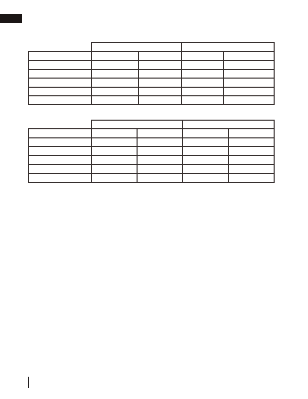
1.1 rates and efficiencies
L38
Single-Sided See-thru
Appliance Type
Fuel Type
Altitude (FT) 0-4,500 0-4,500 0-4,500 0-4,500
Max. Input (BTU/HR) 24,000 24,000 24,000 24,000
Min. Input (BTU/HR) 18,000 21,000 18,000 21,000
P4 38.5% 38.5% 38.5% 38.5%
L38N L38P L38N2 L38P2
Natural Gas Propane Natural Gas Propane
L50
Single-Sided See-thru
Appliance Type
Fuel Type
Altitude (FT) 0-4,500 0-4,500 0-4,500 0-4,500
Max. Input (BTU/HR) 30,000 30,000 30,000 30,000
Min. Input (BTU/HR) 25,000 24,000 25,000 24,000
P4 45.3% 45.3% 45.3% 45.3%
L50N L50P L50N2 L50P2
Natural Gas Propane Natural Gas Propane
6
W415-1707 / 07.04.17
Page 7
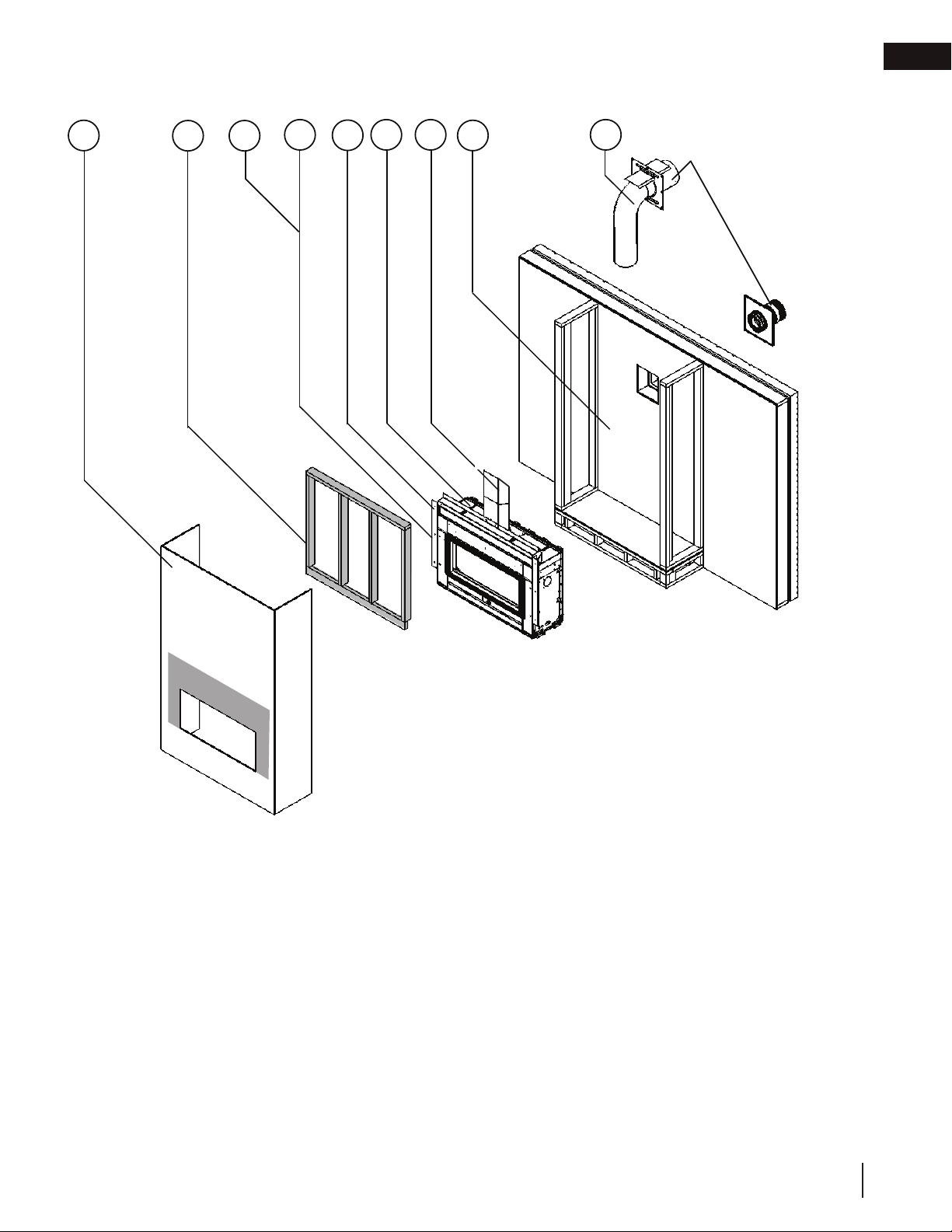
12
11
6
5
9
8
4
7
3
1.2 installation overview
general information
EN
Recommended installation steps:
1. Determine venting requirements before deciding the final location of the appliance
2. Plan out appliance enclosure, framing, fronts, accessories, etc.
3. Install rough framing (refer to “rough framing” section)
4. Place the appliance in its final position
5. Install nailing tabs (refer to “nailing tab installation” section)
6. Install appliance venting (refer to “venting installation” section)
7. Install vent shield (refer to “vent shield installation” section)
8. Install all electrical wirings (refer to “electrical information” section)
9. Install gas lines (refer to “gas installation” section)
10. Test appliance
11. Complete framing (refer to “finish framing” section)
12. Finishing (refer to “finishing” section)
13. Complete installation checklist in the owner’s manual and apply the serial number to the owner’s
manual.
W415-1707 / 07.04.17
7
Page 8
EN
roof joist. If the appliance is installed directly on carpeting, vinyl tile or other combustible material other than wood fl ooring, the
general information
WARNING
!
• Always light the pilot whether for the first time or if the gas supply has run out, with the glass door opened
or removed.
• Provide adequate clearance for servicing and operating the appliance.
• Provide adequate ventilation.
• Never obstruct the front opening of the appliance.
• Objects placed in front of the appliance must be kept a minimum of 48” (121.9cm) from the front face of
the appliance.
• Surfaces around and especially above the appliance can become hot. Avoid contact when appliance is
operating.
• Fire risk. Explosion hazard.
• High pressure will damage valve. Disconnect gas supply piping before pressure testing gas line at test
pressures above 1/2 PSIG. Close the manual shut-off valve before pressure testing gas line at test
pressures equal to or less than 1/2 PSIG (35mb).
• Use only Wolf Steel approved optional accessories and replacement parts with this appliance using nonlisted accessories (blowers, doors, louvres, trims, gas components, venting components, etc.) could result
in a safety hazard and will void the warranty and certification.
• The appliance must not be operated at temperatures below freezing (32ºF / 0ºC). Allow the appliance to
warm to above freezing prior to operation.
• This appliance has been designed and certified for indoor use only.
THIS GAS APPLIANCE MUST BE INSTALLED AND SERVICED BY A QUALIFIED INSTALLER to conform with local
codes. Installation practices vary from region to region and it is important to know the specifi cs that apply to your area, for
example in Massachusetts State:
• This product must be installed by a licensed plumber or gas fi tter when installed within the commonwealth of
Massachusetts.
• The appliance damper must be removed or welded in the open position prior to installation of an appliance insert or gas
log.
• The appliance off valve must be a “T” handle gas cock.
• The fl exible connector must not be longer than 36 inches (0.9m).
• A carbon monoxide detector is required in all rooms containing gas fi red appliances.
• The appliance is not approved for installation in a bedroom or bathroom unless the unit is a direct vent sealed
combustion product.
The installation must conform with local codes or, in absence of local
codes, the National Gas and Propane Installation Code CSA B149.1
in Canada, or the National Fuel Gas Code, ANSI Z223.1 / NFPA 54
in the United States. Suitable for mobile home installation if installed
in accordance with the current standard CAN/CSA Z240MH Series,
for gas equipped mobile homes, in Canada or ANSI Z223.1 and
NFPA 54 in the United States.
The appliance and its individual shutoff valve must be disconnected
from the gas supply piping system during any pressure testing
of that system at test pressures in excess of 1/2 psig (35 mb).
The appliance must be isolated from the gas supply piping system by closing its individual manual shutoff valve during any
pressure testing of the gas supply piping system at test pressures equal to or less than 1/2 psig (35 mb). When installed
with a blower or fan, the junction box must be electrically connected and grounded in accordance with local codes. In the
absence of local codes, use the current CSA C22.1 Canadian Electrical Code in Canada or the ANSI / NFPA 70 National
Electric Code in the United States. In the case where the blower is equipped with a power cord, it must be connected into a
properly grounded receptacle. The grounding prong must not be removed from the cord plug.
The following does not apply to inserts; as long as the required clearance to combustibles is maintained, the most desirable
and benefi cial location for an appliance is in the center of a building, thereby allowing the most effi cient use of the heat
created. The location of windows, doors and, the traffi c fl ow in the room where the appliance is to be located should be
considered. If possible, you should choose a location where the vent will pass through the house without cutting a fl oor or
www.ncertied.org
We suggest that our gas
hearth products be installed
and serviced by professionals
who are certied in the U.S.
by the National Fireplace
®
Institute
(NFI) as NFI Gas
Specialists
appliance shall be installed on a metal or wood panel extending the full width and depth, unless otherwise tested.
8
W415-1707 / 07.04.17
4.1
Page 9
general information
SAMPLE
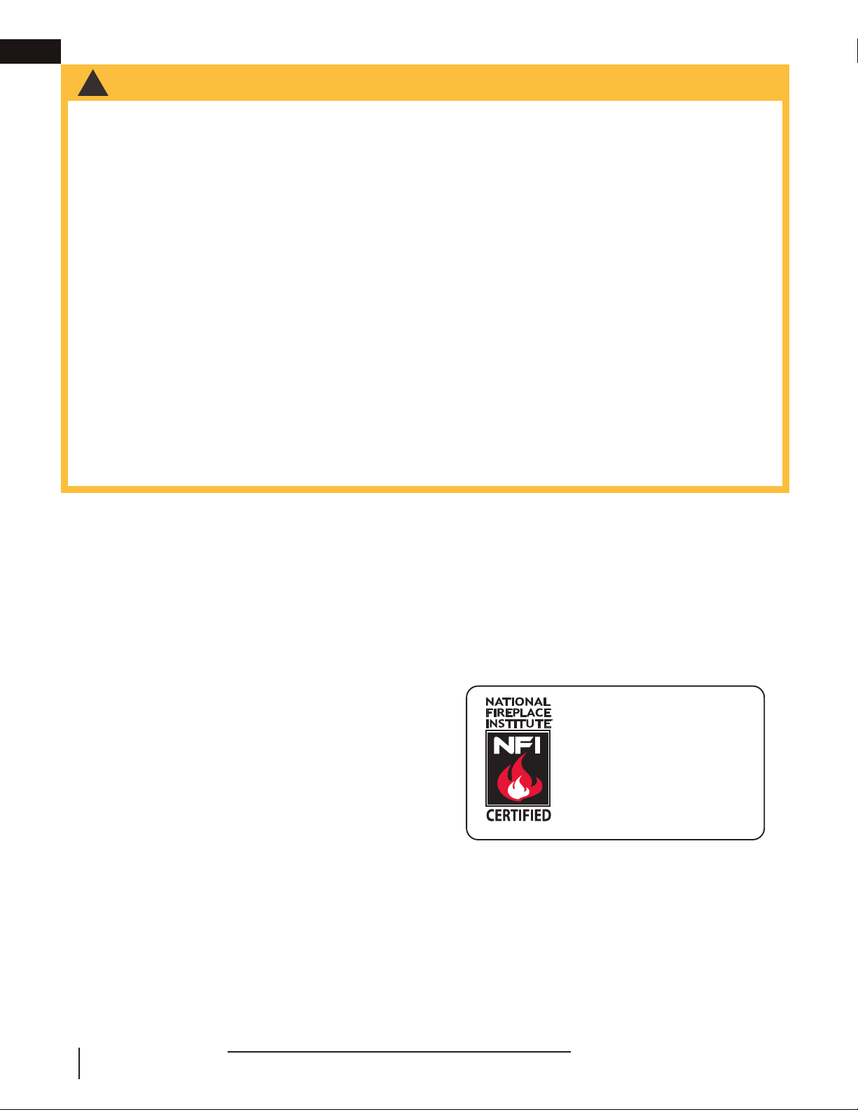
1.3 rating plate/lighting instruction location
Both the rating plate and lighting instructions are attached to a chain located on the left side of the control
area near the valve (access side). Remove the safety barrier and the control cover to gain access to the
control area, refer to the “safety barrier
installation / removal” section for detailed removal instructions.
To replace, slide the instructions back into the control area and reinstall the safety barrier assembly.
Pilot location
access side
EN
Rating plate
location
CERTIFIED TO CANADIAN AND AMERICAN NATIONAL STANDARDS: CSA 2.22-2016 AND ANSI Z21.50-2016 FOR VENTED DECORATIVE GAS FIREPLACES.
CERTIFIÉ SELON LES NORMES NATIONALES CANADIENNES ET AMÉRICAINES: CSA 2.22-2016 ET ANSI Z21.50-2016 POUR LES APPAREILS À GAZ VENTILÉS DÉCORATIFS.
DIRECT VENT, VENTED GAS FIREPLACES. APPROVED FOR BEDROOM, BATHROOM AND BED-SITTING
ROOM INSTALLATION. SUITABLE FOR MOBILE HOME INSTALLATION IF INSTALLED IN ACCORDANCE
WITH THE CURRENT STANDARD CAN/CSA Z240MH SERIES GAS EQUIPPED MOBILE HOMES,
IN CANADA OR IN THE UNITED STATES THE MANUFACTURED HOME CONSTRUCTION AND
SAFETY STANDARD, TITLE 24 CFR, PART 3280. WHEN THIS US STANDARD IS NOT
APPLICABLE USE THE STANDARD FOR FIRE SAFETY CRITERIA FOR MANUFACTURED HOME
INSTALLATIONS, SITES AND COMMUNITIES, ANSI / NFPA 501A. THIS APPLIANCE MUST BE
INSTALLED IN ACCORDANCE WITH LOCAL CODES, IF ANY; IF NONE, FOLLOW THE CURRENT
ANSI Z223.1, OR CSA B149, INSTALLATION CODES.
FOLLOW THE INSTALLATION INSTRUCTIONS LOCATED IN THE INSTALLATION MANUAL.
MANIFOLD PRESSURE: 3.5 INCHES W.C. (NG)
PRESSION AU COLLECTEUR: 3.5" D'UNE
9700539 (WSL) 4001657 (NGZ)
COLONNE D'EAU(GN)
4001658 (NAC) 4001659 (WUSA)
MIN SUPPLY PRESSURE: 4.5" W.C.(NG)
PRESSION D'ALIMENTATION MIN: 4.5" D'UNE
L38N CL38N MODEL CL38P L38P
COLONNE D'EAU (GN)
MAX. SUPPLY PRESSURE: 7"* W.C. (NG)
PRESSION D'ALIMENTATION MAX: 7"* D'UNE
COLONNE D'EAU (GN)
*MAXIMUM INLET PRESSURE NOT TO EXCEED 13".
*PRESSION D'ALIMENTATION MAXIMALE NE DEVAIT PAS DÉPASSER 13".
NOT FOR USE WITH SOLID FUEL. FOR USE WITH GLASS DOORS
CERTIFIED WITH THIS APPLIANCE ONLY.
WARNING:
DO NOT ADD ANY MATERIAL TO THE APPLIANCE, WHICH WILL COME IN CONTACT WITH THE FLAMES, OTHER
THAN THAT SUPPLIED BY THE MANUFACTURER WITH THE APPLIANCE.
MINIMUM CLEARANCE TO COMBUSTIBLE MATERIALS / DÉGAGEMENTS MINIMAUX DES MATÉRIAUX COMBUSTIBLES:
SIDES & BACK: PER STAND OFF SPACERS FOR FRAMING AND FINISHING MATERIALS. FOR NON-COMBUSTIBLE FRAMING AND
FINISHING MATERIALS, SEE INSTALLATION MANUAL. DESSUS, CÔTÉS & ARRIÈRE: SELON LES ESPACEURS DE DÉGAGEMENT
POUR LES MATÉRIAUX D'OSSATURE SELON LA MANUEL DE PROPRIÉTAIRE POUR LES MATÉRIAUX DE FINITION.
TOP / DESSUS 0" RECESSED DEPTH ONE SIDED/ PROFONDEUR D'ENCASTRE UNE FACE 17 15/16"
FLOOR / PLANCHER 0" RECESSED DEPTH SEE THRU/ PROFONDEUR D'ENCASTRE TRAVERS 16 3/16"
SIDES / CÔTÉS 0" BACK / ARRIÈRE 0"
VENT TOP / DESSUS DU CONDUIT D’ÉVENT 3"
VENT SIDES & BOTTOM / CÔTÉS ET DESSOUS DU CONDUIT D'ÉVENT 2"
VERTICAL VENT / CONDUIT D’ÉVENT VERTICAL 1"
MANTEL / TABLETTE 12" *
* MAXIMUM HORIZONTAL EXTENSION / L'EXTENSION HORIZONTALE MAXIMALE: 2". SEE INSTALLATION MANUAL FOR GREATER
EXTENSIONS. RÉFÉRER AU MANUEL D'INSTRUCTION POUR DES EXTENSIONS PLUS GRANDES. SEE INSTALLATION MANUAL FOR
MINIMUM AND MAXIMUM VENT LENGTHS. RÉFÉRER AU MANUEL D'INSTALLATION DE PROPRIÉTAIRE POUR LES LONGUEURS
D'ÉVACUATION MINIMALE ET MAXIMALE.
WOLF STEEL LTD.
FOR USE WITH BARRIER W565-0216.
0-4500FT (0-1370m) ALTITUDE / ÉLÉVATION 0-4500FT (0-1370m)
24,000 BTU/h INPUT / ALIMENTATION 24,000 BTU/h
REDUCED INPUT / ALIMENTATION RÉDUITE
18,000 BTU/h
24 NAPOLEON ROAD, BARRIE, ON, L4M 0G8 CANADA
FOYER À GAZ VENTILÉ. HOMOLOGUÉ POUR INSTALLATION DANS UNE CHAMBRE À COUCHER, UNE
SALLE DE BAIN ET UN STUDIO. APPROPRIÉ POUR INSTALLATION DANS UNE MAISON MOBILE SI
SON INSTALLATION CONFORME AUX EXIGENCES DE LA NORME CAN/CSA Z240MH SÉRIE DE
MAISONS MOBILES ÉQUIPÉES AU GAZ, EN VIGUEUR AU CANADA OU AUX ÉTATS-UNIS DE LA
NORME DE SÉCURITÉ ET DE CONSTRUCTION DE MAISONS MANUFACTURÉES, TITRE 24
CFR, SECTION 3280. DANS LE CAS OU CETTE NORME D'ÉTATS-UNIS NE PEUT ÊTRE
APPLIQUÉE, SE RÉFÉRER A LA NORME RELATIVE AU CRITÈRE DE MESURES DE SÉCURITÉ
CONTRE L'INCENDIE POUR LES INSTALLATIONS DANS LES MAISONS MANUFACTURÉS, LES
SITES ET LES COMMUNAUTÉS, ANSI/NFPA 501A. CODES. INSTALLER L’APPAREIL SELON LES
CODES OU RÈGLEMENTS LOCAUX, OU EN L’ABSENCE DE TELS RÈGLEMENTS, SELON LES
CODES D’INSTALLATION ANSI Z223.1 OU CSA-B149 EN VIGUER.
W565-0216
. SUIVEZ LES INSTRUCTIONS D'INSTALLATION SE TROUVENT DANS LE
BARRIÈRE
21,000 BTU/h
P4
38.5%38.5%
UN COMBUSTIBLE SOLIDE NE DOIT PAS ÊTRE UTILISÉ AVEC
CET APPAREIL. UTILISER AVEC LES PORTES VITRÉES
HOMOLOGUÉES SEULEMENT AVEC CETTE APPAREIL.
AVERTISSEMENT: N’AJOUTEZ PAS A CET APPAREIL AUCUN MATÉRIAU DEVANT ENTRER EN CONTACT AVEC
LES FLAMMES AUTRE QUE CELUI QUI EST FOURNI AVEC CET APPAREIL PAR LE FABRICANT.
THE APPLIANCE MUST BE VENTED USING THE APPROPRIATE NAPOLEON VENT KITS. SEE OWNERS INSTALLATION MANUAL
FOR VENTING SPECIFICS. PROPER REINSTALLATION AND RESEALING IS NECESSARY AFTER SERVICING THE VENT-AIR
INTAKE SYSTEM.
L'APPAREIL DOIT ÉVACUER SES GAZ EN UTILISANT L'ENSEMBLE D'ÉVACUATION PROPRE À NAPOLEON. RÉFÉRER AU
MANUEL D'INSTALLATION DE PROPRIÉTAIRE POUR L'ÉVACUATION PRÉCISE. IL EST IMPORTANT DE BIEN RÉINSTALLER ET
RESCELLER L'ÉVENT APRÈS AVOIR ASSURÉ LE MAINTIEN DU SYSTÈME DE PRISE D'AIR.
SERIAL NUMBER/NO. DE SÉRIE: L38
ELECTRICAL RATING: 115V, 60HZ. LESS THAN 12 AMPERES
SPÉCIFICATIONS ÉLECTRIQUES: 115V, 60HZ. MOINS DE 12 AMPÈRE
DECORATIVE PRODUCT: NOT FOR USE AS A HEATING APPLIANCE
PRODUIT DÉCORATIF: NE PAS UTILISER COMME APPAREIL DE CHAUFFAGE
POUR UNE UTILISER AVEC
MANUEL D'INSTALLATION.
MANIFOLD PRESSURE: 10 INCHES W.C.(P)
PRESSION AU COLLECTEUR: 10" D'UNE
COLONNE D'EAU (P)
MIN SUPPLY PRESSURE: 11" W.C. (P)
PRESSION D'ALIMENTATION MIN: 11" D'UNE
COLONNE D'EAU (P)
MAX. SUPPLY PRESSURE: 13" W.C. (P)
PRESSION D'ALIMENTATION MAX: 13" D'UNE
COLONNE D'EAU (P)
W385-2181
KEEP BURNER AND CONTROL
COMPARTMENT CLEAN. SEE
INSTALLATION AND OPERATING
INSTRUCTIONS MANUAL.
APPLIANCE NEEDS FRESH
AIR FOR SAFE OPERATION
AND MUST BE INSTALLED
WITH ADEQUATE PROVISIONS
FOR COMBUSTION
AND VENTILATION AIR.
GARDEZ LE BRÛLEUR ET LE
COMPARTIMENT DES
CONTRÔLES PROPRES.
CONSULTEZ LE MANUEL
D’INFORMATION ET
D’INSTALLATION. PAR
MESURE DE SÉCURITÉ.
CET APPAREIL DOIT
ÊTRE ALIMENTÉE EN AIR
FRAIS ET AVEC SUFFISANT
D’AIR COMBURANTET
DE VENTILATION.
N'AJOUTEZ PAS A
UN COMBUSTIBLE SOLIDE NE
DOIT PAS ÊTRÉ UTILISÉ AVEC
CET APPAREIL. UTILISER AVEC
LES PORTES VITRÉES
HOMOLOGUÉES SEULEMENT
AVEC CETTE UNITÉ.
AVERTISSEMENT:
CET APPAREIL AUCUN MATÉRIAU DEVANT
ENTRER EN CONTACT AVEC LES FLAMMES
AUTRE QUE CELUI QUI EST FOURNI AVEC
CET APPAREIL PAR LE FABRICANT.
DÉGAGEMENTS MINIMAUX DES
MATÉRIAUX COMBUSTIBLES:
DESSUS 0”
PROFONDEUR D'ENCASTRÉ 25"
PLANCHER 0”
ÉVENT 2"
CÔTES 0”
MANTEAU 15" *
ARRIÉRE 0”
MODEL PROPANE
LHD50PT
0-4500FT (0-1370M)
30,000 BTU/H
23,000 BTU/H
#53
10" WATER COLUMN/D'UNE COLONNE D'EAU
11" WATER COLUMN/D'UNE COLONNE D'EAU
13" WATER COLUMN/ D'UNE COLONNE D'EAU
L'APPAREIL DOIT ÉVACUER SES GAZ EN UTILISANT L'ENSEMBLE
D'ÉVACUATION PROPRE A NAPOLEON. RÉFÉRER AU MANUEL
ALTITUDE / ÉLÉVATION
D'INSTALLATION DE PROPRIÉTAIRE POUR L'ÉVACUATION
INPUT / ALIMENTATION
PRÉCISE. IL EST IMPORTANT DE BIEN RÉINSTALLER ET
ORIFICE / INJECTEUR
RESCELLER L'ÉVENT APRÈS AVOIR ASSURÉ LE MAINTIEN DU
SYSTÉME DE PRISE D'AIR.
MANIFOLD PRESSURE /
PRESSION AU COLLECTEUR
REDUCED INPUT / ALIMENTATION RÉDUITE
MINIMUM SUPPLY PRESSURE /
MAXIMUM SUPPLY PRESSURE /
#38
PRESSION D'ALIMENTATION MINIMALE
PRESSION D'ALIMENTATION MAXIMALE
30,000 BTU/H
INTAKE SYSTEM.
23,000 BTU/H
0-4500FT (0-1370M)
LHD50NT
GAZ NATURAL
MODEL NATURAL GAS /
VENTED GAS FIREPLACE HEATER. APPROVED FOR BEDROOM, BATHROOM AND BED-SITTING ROOM INSTALLATION. SUITABLE FOR MOBILE HOME INSTALLATION IF INSTALLED IN ACCORDANCE WITH THE
CURRENT STANDARD CAN/CSA Z240MH SERIES GAS EQUIPPED MOBILE HOMES, IN CANADA OR IN THE UNITED STATES THE MANUFACTURED HOME CONSTRUCTION AND SAFETY STANDARD, TITLE 24 CFR,
CERTIFIED UNDER / HOMOLOGUE SELON LES NORMES: CSA 2.33b - 2008, ANSI Z21.88b- 2008 VENTED GAS FIREPLACE HEATER / APPAREIL DE CHAUFFAGE ALIMENTÉ
3.5" WATER COLUMN/D'UNE COLONNE D'EAU
PART 3280. WHEN THIS US STANDARD IS NOT APPLICABLE USE THE STANDARD FOR FIRE SAFETY CRITERIA FOR MANUFACTURED HOME INSTALLATIONS, SITES AND COMMUNITIES, ANSI / NFPA 501A.
AU GAZ ET VENTILÉ
FOYER DE CHAUFFAGE AU GAZ AVEC ÉVACUATION. HOMOLOGUÉ POUR INSTALLATION DANS UNE CHAMBRE À COUCHER, UNE SALLE DE BAIN ET UN STUDIO. APPROPRIÉ POUR INSTALLATION DANS UNE
MAISON MOBILE SI SON INSTALLATION CONFORME AUX EXIGENCES DE LA NORME CAN/CSA Z240MH SÉRIE DE MAISONS MOBILES ÉQUIPÉES AU GAZ, EN VIGUEUR AU CANADA OU AUX ÉTATS-UNIS DE LA
4.5" WATER COLUMN/D'UNE COLONNE D'EAU
NORME DE SECURITÉ ET DE CONSTRUCTION DE MAISONS MANUFACTURÉES, TITRE 24 CFR, SECTION 3280. DANS LE CAS OU CETTE NORME D'ÉTATS-UNIS NE PEUT ÊTRE APPLIQUÉE, SE RÉFÉRER A LA NORME
FOR VENTING SPECIFICS. PROPER REINSTALLATION AND
RELATIVE AU CRITÈRE DE MESURES DE SÉCURITÉ CONTRE L'INCENDIE POUR LES INSTALLATIONS DANS LES MAISONS MANUFACTURÉS, LES SITES ET LES COMMUNAUTÉS, ANSI/NFPA 501A.
7.0" WATER COLUMN/D'UNE COLONNE D'EAU
THE APPLIANCE MUST BE VENTED USING THE APPROPRIATE
NAPOLEON VENT KITS. SEE OWNERS INSTALLATION MANUAL
RESEALING IS NECESSARY AFTER SERVICING THE VENT-AIR
W/N 16131
REFERENCE #
DO NOT ADD ANY MATERIAL
:
NOT FOR USE WITH
SOLID FUEL. FOR USE
WITH GLASS DOORS
CERTIFIED WITH THIS
UNIT ONLY.
WARNING
TO THE APPLIANCE, WHICH WILL COME
IN CONTACT WITH THE FLAMES, OTHER
THAN THAT SUPPLIED BY THE
MANUFACTURER WITH THE APPLIANCE.
MINIMUM CLEARANCE TO
COMBUSTIBLE MATERIALS:
TOP 0”
FLOOR 0”
RECESSED DEPTH ONE SIDED 23"
RECESSED DEPTH SEE THRU 13.5”
FRAMING (NOT INCLUDING
FACE MATERIAL)
SIDES 0”
VENT 2"
BACK 0”
MANTLE 15" *
TOP, SIDES & BACK: PER STAND OFF SPACERS FOR FRAMING MATERIALS. FOR FINISHING MATERIALS
WARNING:
IMPROPER INSTALLATION,
ADJUSTMENT, ALTERATION,
SERVICE OR MAINTENANCE
CAN CAUSE PROPERTY DAMAGE,
PERSONAL INJURY OR LOSS OF
LIFE. REFER TO OWNER’S
MANUAL. INSTALLATION AND
SERVICE MUST BE PERFORMED
BY A QUALIFIED INSTALLER,
SERVICE AGENCY OR THE
GAS SUPPLIER.
ATTENTION:
UN INSTALLATION OU UNE
MODIFICATION INAPPROPRIÉE
DU RÉGLAGE, DU SERVICE ET DE
L’ENTRETIEN POURRAIENT ÊTRE
LA CAUSE DE DOMMAGES À LA
PROPRIETÉ DE BLESSURES
CORPORELLES OU MÊME LA
MORT. CONSULTER LE MANUEL
D’INFORMATION, L’INSTALLATION
ET LE SERVICE DOIVENT
ÊTRE EXECUTÉS PAR UN
INSTALLATEUR QUALIFIÉ POUR
LE GAZ, UNE ENTREPRISE DE
SERVICE OU LE FOURNISSEUR
DE GAZ SEULEMENT.
W385-2007
CLASSIFICATION: 115V 0.82AMP, 60HZ
DESSUS, COTÉS & ARRIÈRE: SELON LES ESPACEURS DE DÉGAGEMENT POUR LES MATÉRIAUX D'OSSATURE
SELON LE MANUEL DE PROPRIÉTAIRE POUR LES MATÉRIAUX DE FINITION.
* L'EXTENSION HORIZONTALE MAXIMALE: 2". RÉFÉRER AU MANUEL D'INSTRUCTION POUR DES EXTENSIONS
PLUS GRANDES. RÉFÉRER AU MANUEL D'INSTALLATION DE PROPRIÉTAIRE.
SERIAL NUMBER/NO. DE SÉRIE: LV50
ELECTRICAL RATING: 115V 0.82AMP, 60HZ
MADE IN CANADA / FABRIQUÉ AU CANADA
SEE OWNERS MANUAL
* MAXIMUM HORIZONTAL EXTENSION / L'EXTENSION
HORIZONTALE MAXIMALE: 2". SEE INSTRUCTION MANUAL FOR GREATER EXTENSIONS.
WOLF STEEL LTD. BARRIE, ONTARIO, CANADA
SEE OWNER'S INSTRUCTION MANUAL FOR MINIMUM AND MAXIMUM VENT LENGTHS.
CAUTION:
HOT WHILE OPERATING. DO NOT TOUCH.
KEEP CHILDREN, CLOTHING, FURNITURE,
GASOLINE OR OTHER FLAMMABLE VAPORS
AVERTISSEMENT:
L’APPAREIL EST CHAUD PENDANT SON
FONCTIONNEMENT. LES ENFANTS, LES
VÉTEMENTS, LES MEUBLES, L’ESSENCE ET
AUTRES LIQUIDES QUI ÉMETTENT DES GAZ
VOLATILS INFLAMMABLES DOIVENT
ÉTRE TENUS ÉLOIGNES DE L’APPAREIL.
“This appliance is only for use with the type(s)
of gas indicated on the rating plate and may
be installed in an aftermarket, permanently
located, manufactured home (USA only) or
mobile home, where not prohibited by local
codes. See owner’s manual for details. This
appliance is supplied with a conversion kit.”
«Cet appareil doit être utilisé uniquement
avec les types de gaz indiqués sur la plaque
signalétique et peut être installé dans une
maison préfabriquée (É.-U. seulement) ou
mobile installée à demeure si les règlements
locaux le permettent. Voir la notice de
l’utilisateur pour plus de renseignements. Une
trousse de conversion est fournie avec cet
AWAY.
appareil.»
FOR YOUR SAFETY:
DO NOT STORE OR USE GASOLINE
OR OTHER FLAMMABLE VAPORS
AND LIQUIDS IN VICINITY OF THIS
OR ANY OTHER APPLIANCE.
CAUTION: DO NOT OPERATE
THE FIREPLACE WITH THE GLASS
REMOVED, CRACKED OR BROKEN.
REPLACEMENT OF THE GLASS
SHOULD BE DONE BY A LICENSED
OR QUALIFIED PERSON.
POUR VOTRE
SÉCURITÉ:
NE PAS ENTREPOSER NI UTILISER
D’ESSENCE NI D’AUTRES VAPEURS
OU LIQUIDES INFLAMMABLES
DANS LE VOISINAGE DE CET
APPAREIL OU DE TOUT AUTRE
APPAREIL.
AVERTISSEMENT: NE PAS
UTILISER L’APPAREIL SI LE
PANNEAU FRONTAL EN VERRE
N’EST PAS EN PLACE, EST CRAQUÉ
OU BRISÉ. CONFIEZ LE
REMPLACEMENT DU
PANNEAU À UN
TECHNICIEN
AGRÉÉ.
This illustration is for reference only. Refer to the rating plate on the appliance for accurate information.
note:
The rating plate must remain with the appliance at all times. It must not be removed.
W415-1707 / 07.04.17
9
Page 10
EN
1
2
3
general information
1.4 mobile home installation
This appliance must be installed in accordance with the manufacturer’s instructions and the Manufactured
Home Construction and Safety Standard, Title 24 CFR, Part 3280, in the United States or the Mobile Home
Standard, CAN/CSA Z240 MH Series, in Canada. This appliance is only for use with the type(s) of gas
indicated on the rating plate.
This mobile/manufactured home listed appliance comes factory equipped with a means to secure the appliance. The
shipping brackets that secure the appliance to the pallet can be used to secure the appliance to the floor for mobile
home installation. For mobile home installations, the appliance must be secured.
This appliance is certified to be installed in an aftermarket permanently located, manufactured (mobile) home,
where not prohibited by local codes.
This appliance is only for use with the type of gas indicated on the rating plate. This appliance is not convertible
for use with other gases, unless a certified kit is used.
Conversion Kits
This appliance is field convertible between Natural Gas (NG) and Propane (P).
To convert from one gas to another, consult your Authorized dealer/distributor.
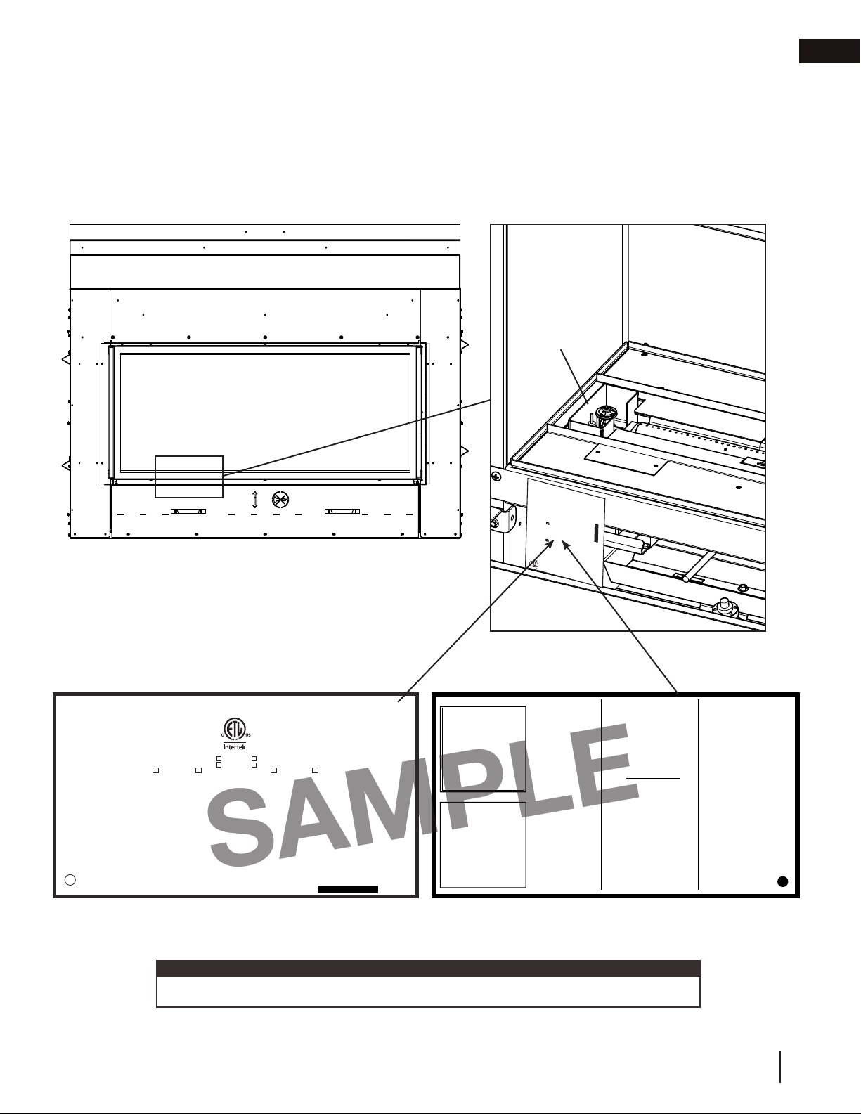
1.5 hardware list
Description Quantity
Hex Head Sheet Metal Screw 22 22
1
Round Head Sheet Metal Screw 4 4
2
Hex Head Sheet Metal Bolt 18 18
3
note:
Only fasteners supplied with the appliance are illustrated.
1.6 lifting handles installation/removal
Secure the lifting handles to the side of the appliance
as shown with the screws supplied. Once the
appliance is in place remove the four screws each
handle to the appliance. Discard the lifting handles.
note:
The lifting handles MUST be removed prior to rough
framing the appliance.
L38 L50
Type 1 (x4)
10
W415-1707 / 07.04.17
Page 11
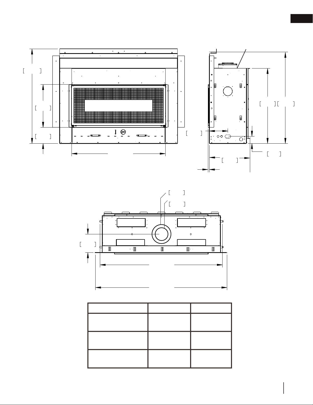
2.1 single-sided
2.0 dimensions
dimensions
Base of air collar
EN
41 3/16"
1046mm
18 5/8"
473mm
7 1/16"
179mm
32 3/4"
39 11/16"
1008mm
3 1/8"
80mm
SAFETY BARRIER
A
203mm
127mm
Ø 8"
Ø 5"
8 1/16"
205mm
1/2"
[12.7mm]
17 11/16"
449mm
*
832mm
8 1/16"
205mm
B
C
L38 L50
A
(Finishing Flange)
B
40 3/4”
(1035mm)
53 5/16”
(1354mm)
C
57 5/16”
(1456mm)
*Finishing flange depth (The finishing flange defines the
perimeter of the fireplace opening. Framing or finishing materials
must NEVER encroach inside the finishing flange
52 3/4”
(1340mm)
65 5/16”
(1659mm)
69 5/16”
(1761mm)
W415-1707 / 07.04.17
11
Page 12
EN
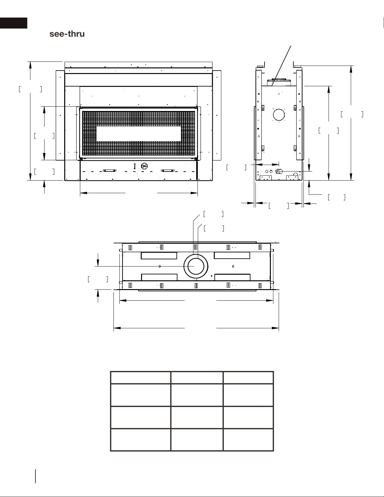
41 3/16"
1046mm
7 1/16"
179mm
18 5/8"
473mm
3 1/8"
80mm
32 3/4"
832mm
39 11/16"
1008mm
16 3/16"
411mm
8 1/16"
205mm
8 1/16"
205mm
Ø 8"
203mm
Ø 5"
127mm
1/2"
[12.7mm]
1/2"
[12.7mm]
dimensions
2.2 see-thru
Base of air collar
SAFETY BARRIER
A
*
*
B
52 3/4”
(1340mm)
65 5/16”
(1659mm)
A
(Finishing Flange)
B
C
40 3/4”
L38 L50
(1035mm)
53 5/16”
(1354mm)
12
W415-1707 / 07.04.17
C
57 5/16”
(1456mm)
69 5/16”
(1761mm)
*Finishing flange depth (The finishing flange defines the perimeter of
the fireplace opening. Framing or finishing materials must NEVER
encroach inside the finishing flange
Page 13

3.0 minimum venting requirements
WARNING
minimum venting requirements
!
• Risk of fi re. Maintain specifi ed air space clearances to vent pipe and appliance.
• If venting is included with spacers, the vent system must be supported every 3’(0.9m) for both vertical and
horizontal runs. Use support ring assembly W010-0067 or equivalent non-combustible strapping to maintain
the minimum clearance to combustibles for both vertical and horizontal runs. Spacers are attached to the
inner pipe at predetermined intervals to maintain an even air gap to the outer pipe. This gap is required
for safe operation. A spacer is required at the start, middle, and end of each elbow to ensure this gap is
maintained. These spaces must not be removed.
This appliance uses a 5” (127mm) exhaust / 8” (203.2mm) air intake vent pipe system. Refer to the
section applicable to your installation.
For safe and proper operation of the appliance follow the venting instructions exactly. Deviation from the
minimum vertical vent length can create difficulty in burner start-up and/or carboning. Under extreme vent
configurations, allow several minutes (5-15) for the flame to stabilize after ignition. Although not a requirement,
it is recommended for vent lengths that pass through unheated spaces (attics, garages, crawl spaces) be
insulated with the insulation wrapped in a protective sleeve to minimize condensation.
Provide a means for visually checking the vent connection to the appliance after the appliance is installed. Use a
firestop, vent pipe shield or attic insulation shield when penetrating interior walls, floor or ceiling.
The vent terminal may be painted with high temperature paint to match exterior colours. Use an outdoor paint
suitable for 400°F (200°C). Application and performance of paint is the consumer’s responsibility. Spot testing is
recommended. Appliance should be off.
EN
note:
If for any reason the vent air intake system is disassembled; reinstall per the instructions provided for the
initial installation.
This appliance must be installed with a continuous connection of exhaust and air intake vent pipes. Utilizing
alternate constructions, such as a chimney as part of the vent system, is not permitted.
All vent measurements start at the base of the air collar of the appliance.
You may reduce the appliance from 5”/8” venting to 4”/7” venting for horizontal and vertical rise applications.
Reducing must be done right off of the appliance and a new firestop spacer (W010-3440) will be required.
W415-1707 / 07.04.17
13
Page 14
EN
minimum venting requirements
Use only Wolf Steel, Simpson Dura-Vent, Selkirk Direct Temp, American Metal Amerivent or Metal-Fab venting
components. Minimum and maximum vent lengths, for both horizontal and vertical installations, clearances from
vent pipes to combustibles and air terminal locations as set out in this manual apply to all vent systems and
must be adhered to. For Simpson Dura-Vent, Selkirk Direct Temp, American Metal Amerivent and Metal-Fab,
follow the installation procedure provided with the venting components. A starter adaptor must be used with the
following vent systems and may be purchased from the corresponding supplier:
Vent
Manufacturer
Duravent W175-0170 Wolf Steel www.duravent.com
Amerivent 5DSC-N2 American Metal www.americanmetalproducts.com
Direct Temp 5DT-AA Selkirk www.selkirkcorp.com
SuperSeal 5DNA Metal-Fab www.mtlfab.com
For vent systems that provide seals on the inner exhaust flue, only the outer air intake joints must be sealed using
a red high temperature silicone (RTV). This same sealant may be used on both the inner exhaust and outer intake
vent pipe joints of all other approved vent systems except for the exhaust vent pipe connection to the appliance
flue collar which must be sealed using the black high temperature sealant Mill Pac.
When using Wolf Steel venting components, use only approved Wolf Steel flexible components with the wall
terminal kit GD422R-2, or 1/12 to 7/12 pitch roof terminal kit GD410, 8/12 to 12/12 roof terminal kit GD411,
flat roof terminal kit GD412 or periscope kit GD401 (for wall penetration below grade). With flexible venting, in
conjunction with the various terminations, use either the 5 foot (1.5m) vent kit GD420 or the 10 foot (3.1m) vent
kit GD430.
For optimum flame appearance and appliance performance, keep the vent length and number of elbows to
a minimum.
Horizontal runs may have a 0” (0mm) rise per foot/meter however for optimum performance it is
recommended that all horizontal runs have a minimum 1/4” (21mm) rise per foot/meter using flexible
venting. For safe and proper operation of the appliance, follow the venting instructions exactly.
The air terminal must remain unobstructed at all times. Examine the air terminal at least once a year
to verify that it is unobstructed and undamaged.
Rigid and flexible venting systems must not be combined. Different venting manufacturer components
must not be combined.
Starter Adapter Part
Number
Supplier Website
14
These vent kits allow for either horizontal or vertical venting of the appliance. The maximum allowable vertical
vent length is 40 feet (12.2m). The maximum number of vent connections is two horizontally or three vertically
(excluding the appliance and the air terminal connections) when using flexible venting.
A terminal shall not terminate directly above a sidewalk or paved driveway which is located between two single
family dwellings and serves both dwellings. Local codes or regulations may require different clearances.
Do not allow the inside liner to bunch up on horizontal or vertical runs and elbows. Keep it pulled tight. A 1¼”
(31.8mm) air gap all around between the inner liner and outer liner is required for safe operation.
For 4”/7” (Use reducer kit A4758AK to transition from 5”/8” to 4”/7” venting)
When using Wolf Steel 4”/7” venting components, use only approved Wolf Steel flexible components with the
following termination kits: wall terminal kit GD222, GD222R, or 1/12 to 7/12 pitch roof terminal kit GD110, 8/12
to 12/12 roof terminal kit GD111, flat roof terminal kit GD112 or periscope kit GD201 (for wall penetration below
grade). With flexible venting, in conjunction with the various terminations, use either the 5 foot (1.5m) vent kit
GD220 or the 10 foot (3.1m) vent kit GD330. See 4/7” vent clearance to combustibles section for specific venting
parameters. See detailed instructions
W415-1707 / 07.04.17
Page 15
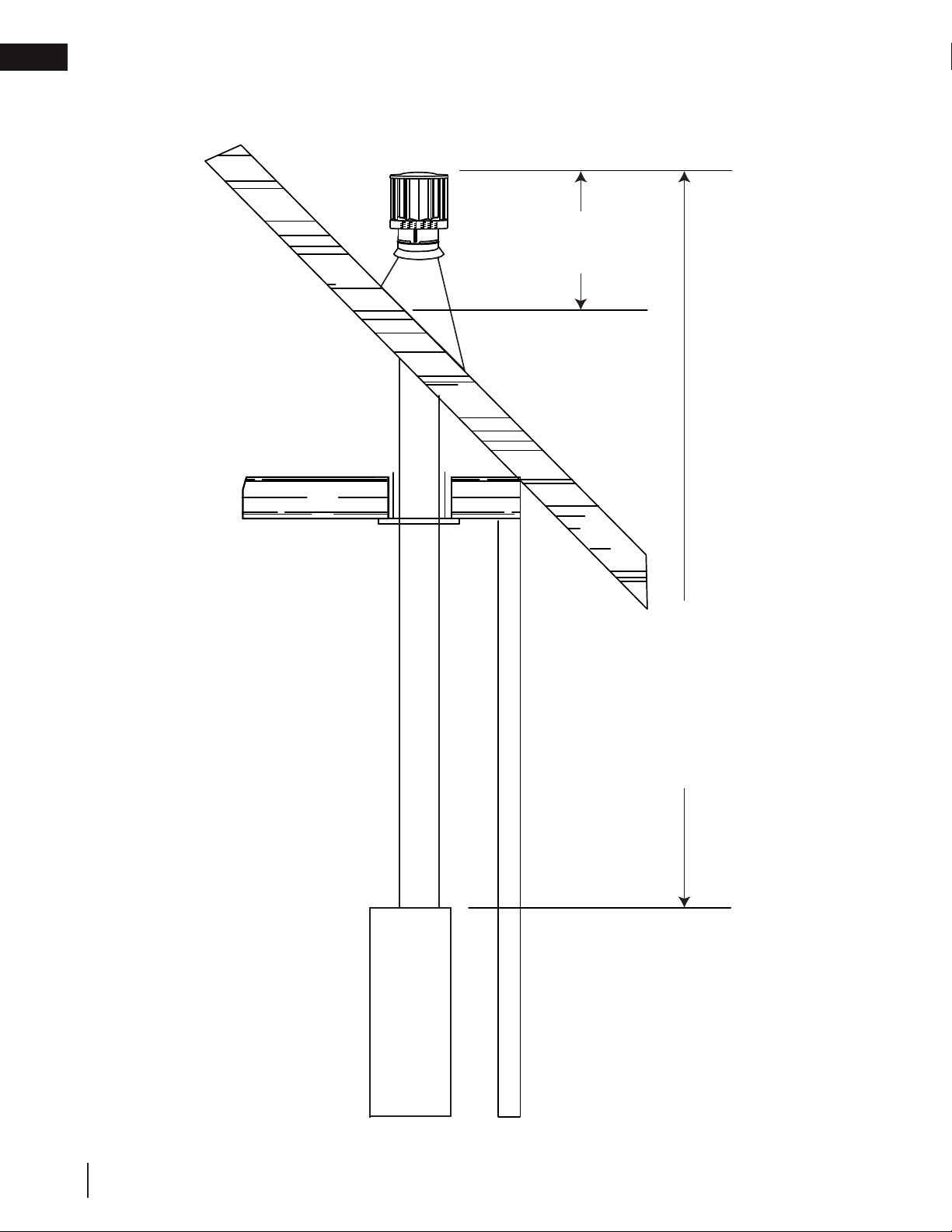
3.1 typical venting installation
18"
(45.7cm)
maximum
15"
(38.1cm)
minimum
base of
air collar
47 3/4"
(121.3cm)
minimum plus rise
minimum venting requirements
D
15"
(38.1cm)
minimum
base of
air collar
minimum plus rise
EN
47 3/4"
(121.3cm)
SINGLE-SIDED
SEE-THRU
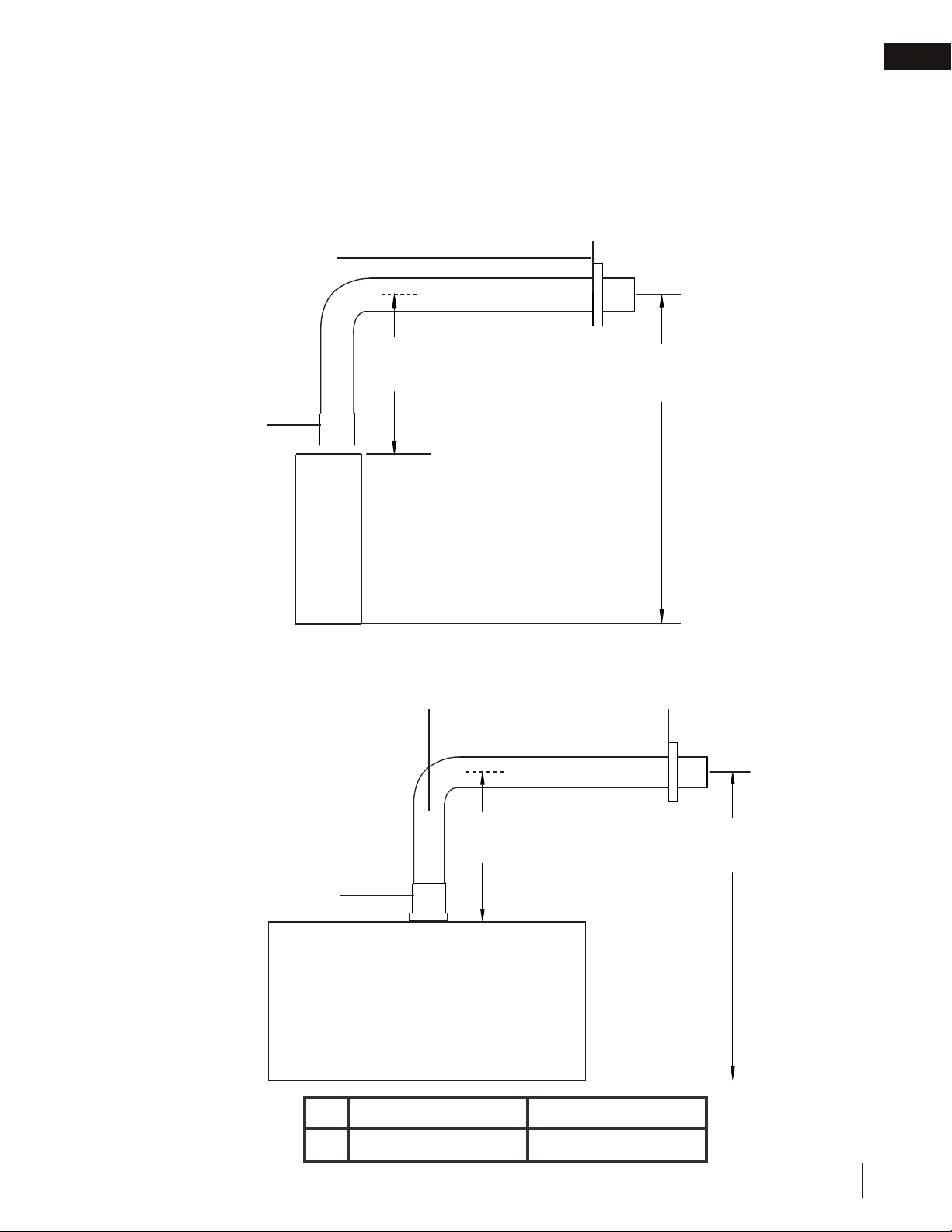
special vent installation (periscope termination)
Use the periscope kit to locate the air termination above grade. The periscope must be installed so that when
final grading is completed, the bottom air slot is located a minimum 12” (30.5cm) above grade. The maximum
allowable vent length is 10’ (3m) for a fireplace and 8’ (2m) for a stove.
D
12"
(30.5cm)
minimum
to grade
30”
(76.2cm)
minimum
base of air collar
base of air collar
30”
(76.2cm)
minimum
12"
(30.5cm)
minimum
to grade
SINGLE-SIDED
D
SEE-THRU
L38 L50
40” (101.6cm) 46 1/2” (118.1cm)
W415-1707 / 07.04.17
15
Page 16
EN
minimum venting requirements
SINGLE-SIDED OR SEE-THRU
16" (40.6cm)
minimum
40 ft (12m)
maximum
6 ft (1.83m)
minimum
base of air collar
16
W415-1707 / 07.04.17
Page 17
minimum venting requirements
4/7” vent clearance to combustibles
If necessary, 5/8” venting can be reduced to 4/7” venting.
The minimum clearances around the horizontal vent pipe to the combustible material is 1" (25.4mm) in
installations with a minimum of 30” (76.2cm) vertical rise made immediately off the appliance collar and where
the vent has been reduced to a 4/7" from 5/8" at the appliance.
EN
SINGLE-SIDED
reducer
30" min
(76.2cm)
D
62 3/4"
(156.4cm)
base of air collar
SEE-THRU
reducer
D
D
30" min
(76.2cm)
base of air collar
L38 L50
40” (101.6cm) 46 1/2” (118.1cm)
62 3/4”
(156.4cm)
W415-1707 / 07.04.17
17
Page 18

EN
minimum venting requirements
converting from 5/8" to 4/7" venting
1 2
USE MILL PAC TO SEAL REDUCER TO THE APPLIANCE EXHAUST COLLARS.
3
USE RED SILICONE TO SEAL REDUCER TO THE AIR INTAKE COLLARS.
4
5 6
X3
X3
X3
18
USE RED SILICONE TO SEAL REDUCER TO THE AIR INTAKE COLLARS.
W415-1707 / 07.04.17
Page 19
minimum venting requirements
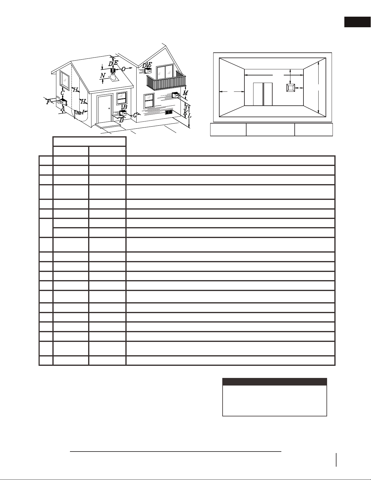
Covered balcony applications ††*
Q
MIN
R
MAX
MAX
R
= 3 feet
(0.9m)
= 2 x
≤ 15 feet
(4.6m)
Q
ACTUAL
R
Q
S
G
P
INSTALLATIONS
CANADA U.S.A.
A
12” (30.5cm) 12” (30.5cm) Clearance above grade, veranda porch, deck or balcony.
B
12” (30.5cm)
Δ
9” (229mm) Clearance to windows or doors that open.
C
12” (30.5cm)* 9” (229mm) * Clearance to permanently closed windows.
D
18”
(45.7cm)**
18”
(45.7cm)**
Vertical clearance to ventilated soffi ts located above the terminal within a horizontal distance of 2’
(0.6m) from the center line of the terminal.
E
12” (30.5cm)** 12” (30.5cm)** Clearance to unventilated soffi t.
F
0” (0mm) 0” (0mm) Clearance to an outside corner wall.
G
0” (0mm)*** 0” (0mm)***
Clearance to an inside non-combustible corner wall or protruding non-combustible obstructions (chimney, etc.).
2” (51mm)*** 2” (51mm)*** Clearance to an inside combustible corner wall or protruding combustible obstructions (vent chase, etc.).
H
3’(0.9m) 3’(0.9m)****
Clearance to each side of the center line extended above the meter / regulator assembly to a maxi-
mum vertical distance of 15’ (4.6m).
I
3’ (0.9m) 3’ (0.9m)**** Clearance to a service regulator vent outlet.
J
12” (30.5cm) 9” (229mm) Clearance to a non-mechanical air supply inlet to the building or a combustion air inlet to any other appliance.
K
6’ (1.8m) 3’ (0.9m) † Clearance to a mechanical air supply inlet.
L
7’ (2.1m) ‡ 7’ (2.1m) **** Clearance above a paved sidewalk or paved driveway located on public property.
M
12” (30.5cm)†† 12” (30.5cm)**** Clearance under a veranda, porch or deck.
N
16” (40.6cm) 16” (40.6cm) Clearance above the roof.
O
2’ (0.6m)†* 2’ (0.6m) †* Clearance from an adjacent wall including neighbouring buildings.
P
8’ (2.4m) 8’ (2.4m)
Roof must be non-combustible without openings.
Q
3’ (0.9m) 3’ (0.9m) See chart for wider wall dimensions.
R
6’ (1.8m) 6’ (1.8m)
See chart for deeper wall dimensions. The terminal shall not be installed on any wall that has an
opening between the terminal and the open side of the structure.
S
12” (30.5cm) 12” (30.5cm) Clearance under a covered balcony
Δ The terminal shall not be located less than 6 feet under a window that opens on a horizontal plane in a structure with three walls and a roof.
* Recommended to prevent condensation on windows and thermal breakage
** It is recommended to use a heat shield and to maximize the distance to vinyl clad soffi ts.
*** The periscope requires a minimum 18 inches clearance from an inside corner.
**** This is a recommended distance. For additional requirements, check local codes.
† 3 feet above if within 10 feet horizontally.
‡ A vent shall not terminate where it may cause hazardous frost or ice accumulations on adjacent property surfaces.
†† Permitted only if the veranda, porch, or deck is fully open on a minimum of two sides beneath the fl oor.
†* Recommended to prevent recirculation of exhaust products. For additional requirements, check local codes.
††* Permitted only if the balcony is fully open on a minimum of one side.
In the absence of local codes and
gas supplier requirements, installation
must be done in accordance to the
national country requirements.
note:
9.1
3.2 minimum air terminal location clearances
Covered balcony applications ††*
Q
S
R
G
EN
P
Q
= 3 feet
MIN
(0.9m)
R
MAX
INSTALLATIONS
CANADA U.S.A.
12” (30.5cm) 12” (30.5cm) Clearance above grade, veranda porch, deck or balcony.
A
Δ
12” (30.5cm)
B
12” (30.5cm)* 9” (229mm) * Clearance to permanently closed windows.
C
D
E
F
G
H
I
J
K
L
M
N
O
P
Q
R
S
Δ The terminal shall not be located less than 6 feet under a window that opens on a horizontal plane in a structure with three walls and a roof.
* Recommended to prevent condensation on windows and thermal breakage
** It is recommended to use a heat shield and to maximize the distance to vinyl clad soffi ts.
*** The periscope requires a minimum 18 inches clearance from an inside corner.
**** This is a recommended distance. For additional requirements, check local codes.
† 3 feet above if within 10 feet horizontally.
‡ A vent shall not terminate where it may cause hazardous frost or ice accumulations on adjacent property surfaces.
†† Permitted only if the veranda, porch, or deck is fully open on a minimum of two sides beneath the fl oor.
†* Recommended to prevent recirculation of exhaust products. For additional requirements, check local codes.
††* Permitted only if the balcony is fully open on a minimum of one side.
18”
(45.7cm)**
12” (30.5cm)** 12” (30.5cm)** Clearance to unventilated soffi t.
0” (0mm) 0” (0mm) Clearance to an outside corner wall.
0” (0mm)*** 0” (0mm)***
2” (51mm)*** 2” (51mm)*** Clearance to an inside combustible corner wall or protruding combustible obstructions (vent chase, etc.).
3’(0.9m) 3’(0.9m)****
3’ (0.9m) 3’ (0.9m)**** Clearance to a service regulator vent outlet.
12” (30.5cm) 9” (229mm) Clearance to a non-mechanical air supply inlet to the building or a combustion air inlet to any other appliance.
6’ (1.8m) 3’ (0.9m) † Clearance to a mechanical air supply inlet.
7’ (2.1m) ‡ 7’ (2.1m) **** Clearance above a paved sidewalk or paved driveway located on public property.
12” (30.5cm)†† 12” (30.5cm)**** Clearance under a veranda, porch or deck.
16” (40.6cm) 16” (40.6cm) Clearance above the roof.
2’ (0.6m)†* 2’ (0.6m) †* Clearance from an adjacent wall including neighbouring buildings.
8’ (2.4m) 8’ (2.4m)
3’ (0.9m) 3’ (0.9m) See chart for wider wall dimensions.
6’ (1.8m) 6’ (1.8m)
12” (30.5cm) 12” (30.5cm) Clearance under a covered balcony
9” (229mm) Clearance to windows or doors that open.
18”
(45.7cm)**
Vertical clearance to ventilated soffi ts located above the terminal within a horizontal distance of 2’
(0.6m) from the center line of the terminal.
Clearance to an inside non-combustible corner wall or protruding non-combustible obstructions (chimney, etc.).
Clearance to each side of the center line extended above the meter / regulator assembly to a maximum vertical distance of 15’ (4.6m).
Roof must be non-combustible without openings.
See chart for deeper wall dimensions. The terminal shall not be installed on any wall that has an
opening between the terminal and the open side of the structure.
note:
In the absence of local codes and
gas supplier requirements, installation
must be done in accordance to the
national country requirements.
= 2 x
Q
ACTUAL
W415-1707 / 07.04.17
R
MAX
≤ 15 feet
(4.6m)
19
Page 20
EN
minimum venting requirements
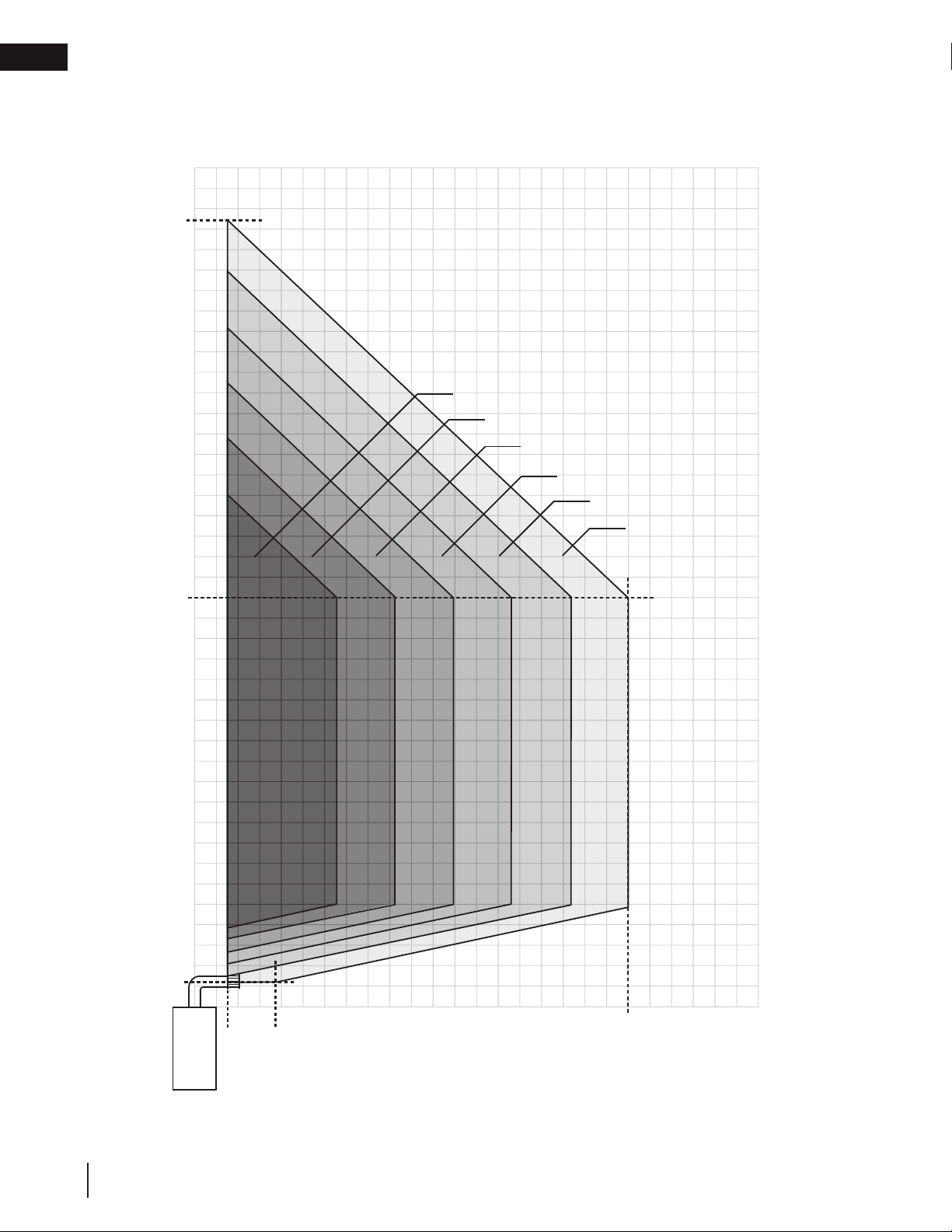
3.3 horizontal termination
40’
38’ 6”
V+H ≤ 40 ft.
H ≤ 20 ft.
V + H are measured from the centre of vent
elbows. Elbows are considered as 90º.
Two 45º elbows = One 90º elbow.
L38 / L50
V
30’
20’
15’
10’
1-6 elbow zone
1-5 elbow zone
1-4 elbow zone
1-3 elbow zone
1-2 elbow zone
1 elbow zone
20
5’
1.25’ (15”)
0’
0’
W415-1707 / 07.04.17
1.5’
(18”)
3.875’
(46”)
5’
10’
15’
20’
25’
H
Page 21

minimum venting requirements
40’
V = V1 + V2 = 8 ft
EN
90°
90°
H
= H1 + H2
30’
H
2
V
2
20’
V
H
1
15’
V
1
Base of
air collar
1-3 elbow zone
= 10 ft
10’
H
2
V
2
10’
15’
0’
Base of
air collar
H
1
5’
V
1
5’
H
0’
V and H are measured from the center of the vent elbows
This example represents a vent that has a maximum of three 90º elbows, a combined horizontal vent length (H ) of
10 feet and a combined vertical vent length (V ) of 8 feet.
Since the vent is located in the dark shaded area, it is within the acceptable vent configuration
20’
W415-1707 / 07.04.17
21
Page 22

EN
minimum venting requirements
3.4 vertical termination
L38 / L50
40’
30’
20’
0 elbow zone
V+H ≤ 40 ft. (For longer vent runs,
a power vent is required).
H ≤ 20 ft.
V + H are measured from the
centre of vent elbows. Elbows are
considered as 90º.
Two 45º elbows = One 90º elbow.
2-7 elbow zone
2-6 elbow zone
2-5 elbow zone
2-4 elbow zone
2-3 elbow zone
2 elbow zone
22
0’
Base of
air collar
W415-1707 / 07.04.17
6’
15’
10’
5’
5’
0’
10’
15’
20’
Page 23

4.0 rough framing - before appliance installation
!
WARNING
note:
When using optional fi nishing accessories, the framing dimensions and fi nishing materials may differ from
what is outlined in the section below; refer to the leafl et instructions supplied in the accessory kit for specifi c
framing and fi nishing specifi cations.
• Risk of fi re!
• In order to avoid the possibility of exposed insulation or vapour barrier coming in contact with the appliance
body, it is recommended that the walls of the appliance enclosure be “fi nished” (i.e. drywall / sheetrock),
as you would fi nish any other outside wall of a home. This will ensure that clearance to combustibles is
maintained within the cavity.
• Do not notch the framing around the appliance stand offs. Failure to maintain air space clearance may cause
over heating and fi re. Prevent contact with sagging or loose insulation or framing and other combustible
materials. Block opening into the chase to prevent entry of blown-in insulation. Make sure insulation and
other materials are secured.
• When constructing the enclosure allow for fi nishing material closer than the minimums listed must be
constructed entirely of non-combustible materials. Materials consisting entirely of steel, iron, brick, tile,
concrete, slate, glass or plasters, or any combination thereof are suitable. Materials that are reported as
passing ASTM E136, standard test method for behaviour of materials in a vertical tube furnace at 1382ºF
(750ºC) and UL763 shall be considered non-combustible materials.
• Minimum clearance to combusibles must be maintained or a serious fi re hazard could result.
• The appliance requires a minimum enclosure height. Measure from the appliance base.
• If steel stud framing kits with cement board are provided, or specifi ed in the installation instructions, they
must be installed.
• If specifi ed in the installation instruction, fi nishing must be done using a non-combustible board, ceramic tile,
marble, etc. Do NOT use wood or drywall. Any fi re rated drywall is not acceptable.
rough framing - before appliance installation
EN
note:
For heavier finishing materials such as marble, we recommend adding extra support to the frame. Ensure
there is adequate floor support for the appliance and finishing material.
W415-1707 / 07.04.17
23
Page 24

EN
Do not put objects in front of the
appliance (minimum distance of 4 feet)
rough framing - before appliance installation
4.1 minimum framing dimensions
6” (15.2cm) min.
H
F
G
1” (2.54cm) min.
F
I
E
minimum framing
L38 L50
E
F
18” (45.7cm) 18” (45.7cm)
53 13/16” (136.7cm) 65 13/16” (167.2cm)
24
W415-1707 / 07.04.17
G
H
I
63 3/4” (162cm) 72 1/4” (183.5cm)
18 3/16” (46.2cm) 18 3/16” (46.2cm)
90 3/16” (229cm) 102 3/16” (259.5cm)
Page 25

rough framing - before appliance installation
4.1.1 minimum clearance to combustible enclosures
single-sided
note:
Shaded components (finish framing) must be noncombustible materials.
1” [25mm] minimum
all sides for vertical
venting.
When passing through
a ceiling, use firestop
spacer W500-0028
(not supplied)
EN
6” [152mm] minimum
3” [76mm] top
2” [51mm] sides /
bottom
0” to non-combustible
finishing such as brick
and stone
When passing through
a wall, use firestop
spacer W615-0162
(supplied with W0104178 firestop spacer
assembly)
0” to side standoffs
1/2” finishing flange
0” to bottom of the
appliance
74”
minimum
0” to back standoffs
note:
The L series requires a minimum
inside enclosure height of 74” measured from the bottom of the appliance. For temperature requirements,
this area must be left unobstructed.
It is also recommended that the
enclosure be ventilated at the top and
bottom to circulate the hot air.
W415-1707 / 07.04.17
25
Page 26

EN
rough framing - before appliance installation
see-thru
1” [25mm]
minimum all
sides for vertical
venting.
When passing
through a
ceiling, use
firestop spacer
W500-0028 (not
supplied)
note:
Shaded components must be non-combustible
materials.
6” [152mm] minimum
3” [76mm] top
2” [51mm] sides /
bottom
0” to noncombustible finishing
such as brick and
stone
When passing
through a wall, use
firestop spacer
W615-0162 (supplied with W0104178 firestop spacer
assembly)
74”
minimum
SAFETY BARRIER
0” to side standoffs
1/2” finishing flange
(4 sides)
0” to base of the
appliance
26
W415-1707 / 07.04.17
Page 27

rough framing - before appliance installation
Before framing your appliance, determine vent requirements before deciding the final location of the appliance.
After rough framing, place the appliance in its final position.
single-sided
Before framing the appliance, ensure to install the
firestop first as it will not fit between the studs if
installed after framing.
L
E
J
F
EN
see-thru
minimum framing
Ref L38 L50
E
F
J
*L
18” (45.7cm) 18” (45.7cm)
53 13/16” (136.7cm) 65 13/16” (167.2cm)
Optional - Appliance does not need to be elevated above floor
74” (188cm) 74” (188cm)
Before framing the appliance, ensure to install the
firestop first as it will not fit between the studs if
installed after framing.
L
E
F
minimum framing
J
Ref L38 L50
E
F
J
*L
16 3/16” (41.1cm) 16 3/16” (41.1cm)
53 13/16” (136.7cm) 65 13/16” (167.2cm)
Optional - Appliance does not need to be elevated above floor
74” (188cm) 74” (188cm)
*Minimum enclosure
height maybe higher depending on venting configuration (See minimum
distance to combustibles
W415-1707 / 07.04.17
27
Page 28

EN
42.1
!
WARNING
venting installation
5.0 venting installation
• Ensure to unpack all loose materials from inside the fi rebox prior to connecting the gas and electrical supply
• If your appliance is supplied with a remote, ensure the remote receiver is in the “OFF” position prior
to connecting the gas and electrical supply to the appliance.
• For safe and proper operation of the appliance, follow the venting instructions exactly.
• The appliance exhaust fl ue collar must be sealed using Mill Pac. All exhaust and intake vent pipe joints
must be sealed using red RTV high temp silicone sealant (W573-0002) (not supplied) or black high temp Mill
Pac (W573-0007) (not supplied).
• If using pipe clamps to connect rigid vent components, a minimum of 3 screws must also be used to ensure
the connection cannot slip off.
• Do not clamp the fl exible vent pipe.
• Risk of fi re, explosion, or asphyxiation. Improper support of the entire venting system may allow vent to sag
and separate. Use vent run supports and connect vent sections per installation instructions.
• Risk of fi re, do not allow loose materials or insulation to touch the vent pipe. Remove insulation to allow for the
installation of the attic shield and to maintain clearances to combustibles.
• Do not fi ll the space between the vent pipe and enclosure with any type of material. Do not pack insulation
or combustibles between ceiling fi restops. Always maintain specifi ed clearances around venting and fi restop
systems. Install wall shields and fi restops as specifi ed. Failure to keep insulation or other materials away from
vent pipe may cause fi re.
For optimum performance, it is recommended that all horizontal runs have a minimum of 1/4" (6mm) rise per
foot using flexible venting.
note:
The vent shield is telescopic and must be adjusted to shield the first 15” (38.1cm) of vertical vent when applicable.
For vent shield installation, see section “vent shield installation”
Power vent system available with reduced vent pipe diameter.
5.1 firestop spacer assembly
1. Install firestop standoffs onto the firestop spacer (Figure 1).
2. Install firestop vent shield below the top firestop standoff (Figure 2).
3. Install the other firestop vent shield on the opposite side (Figure 3).
Fig. 1
Type 3 (x18)
Fig. 2
28
W415-1707 / 07.04.17
Fig. 3
Page 29

venting installation
4. Bend vent sleeve as shown and ensure to clip the ends together (Figure 4).
5. Ensure both ends line up and secure ends with clip and fasteners (Figure 5).
EN
Fig. 4
Fig. 5
6. Insert the vent sleeve tabs into the firestop spacer sockets, bend vent sleeve tabs, and secure to the firestop spacer with 4 supplied fasteners (Figure 6).
Fig. 6
W415-1707 / 07.04.17
29
Page 30

EN
This application occurs when venting through a roof. Installation kits for
between the pipe and the fi restop.
WARNING
venting installation
5.2 horizontal installation
!
• The fi restop assembly must be installed with the vent shield to the top.
• Terminals must not be recessed into a wall or siding more than the depth of the return fl ange of the mounting
plate.
This application occurs when venting through an exterior
wall. Having determined the correct height for the air
terminal location, cut and frame a hole in the exterior wall,
as illustrated, to accommodate the fi restop assembly. Dry
fi t the fi restop assembly before proceeding to ensure the
brackets on the rear surface fi t to the inside surface of the
horizontal framing.
The length of the vent shield may be cut shorter for
combustible walls that are less than 8 1/2” (215.9mm)
thick but the vent shield must extend the full depth of the
combustible wall.
note:
Do not fi ll the air space between the fi restop spacer and the
exterior wall with any type of insulating material (i.e. spray foam).
CAULKING
CAULKING
FIRESTOP
FIRESTOP
SPACER
SPACER
RED RTV
VENT
VENT
SHIELD
SHIELD
FINISHING
MATERIAL
FINISHING
MATERIAL
VENT
SLEEVE
DETERMINE
DETERMINE
THE
THE
CORRECT
CORRECT
HEIGHT
HEIGHT
A. Apply a bead of caulking (not supplied) around the outer edge of
the hole of the fi restop assembly, fi t the fi restop assembly to the
hole and secure using 4 screws.
B. Once the vent pipe is installed in its fi nal position, apply red RTV silicone (W573-0002) (not supplied)
5.3 vertical installation
various roof pitches are available from your authorized dealer / distributor.
See the “accessories” section to order specifi c kits required.
A. Determine the air terminal location, cut and frame a square opening,
as illustrated, in the ceiling and the roof to provide the minimum 1"
(25mm) clearance between the vent pipe and any combustible material.
Try to center the vent pipe location midway between two joists to
prevent having to cut them. Use a plumb bob to line up the center of
the openings. A vent pipe shield will prevent any materials such as
insulation, from fi lling up the 1" (25mm) air space around the pipe. Nail
headers between the joist for extra support.
B. Apply a bead of caulking (not supplied) to the framework or to the
Wolf Steel vent pipe shield plate or equivalent (in the case of a fi nished
ceiling), and secure over the opening in the ceiling. A fi restop must be
placed on the bottom of each framed opening in a roof or ceiling that
the venting system passes through. Apply a bead of caulking all around
and place a fi restop spacer over the vent shield to restrict cold air from
being drawn into the room or around the fi replace. Ensure that both
spacer and shield maintain the required clearance to combustibles.
Once the vent pipe is installed in its fi nal position, apply Mill Pac sealant
(W573-0007) (not supplied) or red RTV silicone (W573-0002) (not
supplied) between the pipe and the fi restop assembly.
C. In the attic, slide the vent pipe collar down to cover up the open end
of the shield and tighten. This will prevent any materials, such as
insulation, from fi lling up the 1" (25mm) air space around the pipe.
10 3/4"
(273mm)
Vent Pipe
Shield
Vent
Pipe
Shield
10 3/4"
(273mm)
Firestop
underside
of joist
Caulking
Vent
Pipe
Collar
30
W415-1707 / 07.04.17
Page 31

venting installation
“Wolf Steel Approved Venting” or “E2” as identifi ed by the stamp only on the fl ex pipes.
!
WARNING
A. Stretch the inner fl ex pipe to the required length taking
depth of its return fl ange.
ADD FASTENER TYPE
Screws
(Supplied)
2" (50.8mm) Overlap
Outer Flex Pipe
Inner Flex
Pipe
Red RTV Silicone
Caulking
Red RTV Silicone
Screws
Inner Coupler
Outer Coupler
Outer Flex
Pipe
Inner Flex
Pipe
Outer Flex
Pipe
Screws
(Supplied)
2" (50.8mm) Overlap
Outer Flex Pipe
Inner Flex
Pipe
Red RTV Silicone
Caulking
5.4 using flexible vent components
• Do not allow the inner fl ex pipe to bunch up on horizontal or vertical runs and elbows. Keep it pulled tight.
• Spacers are attached to the inner fl ex pipe at predetermined intervals to maintain an even air gap to the outer
fl ex pipe. This gap is required for safe operation. A spacer is required at the start, middle, and end of each
elbow to ensure this gap is maintained. These spacers must not be removed.
For safe and proper operation of the appliance, follow the venting instructions
exactly.
Elbow
Spacers
The vent system must be supported approximately every 3 feet (0.9m) for
both vertical and horizontal runs. Use Wolf Steel Ltd. support ring assembly
or equivalent noncombustible strapping to maintain the minimum clearance to
combustibles for both vertical and horizontal runs.
All inner fl ex pipe and outer fl ex pipe joints may be sealed using high temperature
red RTV silicone W573-0002 (not supplied) or the high temperature sealant W5730007 Mill Pac (not supplied). However, the high temperature sealant W573-0007
Mill Pac (not supplied) must be used on the joint connecting the inner fl ex pipe and
the exhaust fl ue collar.
Use only approved fl exible vent pipe kits marked:
EN
5.4.1 horizontal air terminal installation
into account the additional length needed for the fi nished
B. Using the outer fl ex pipe, slide over the outer combustion
C. Insert the vent pipes through the fi restop maintaining
D. If more vent pipe needs to be used to reach the fi replace,
E. Stove Appliances Only: From inside the house, using
The air terminal mounting plate may be recessed into the exterior wall or siding no greater than the
wall surface. Apply a heavy bead of the red RTV silicone
(W573-0002) (not supplied) to the inner sleeve of the air
terminal. Slip the vent pipe a minimum of 2” (50.8mm)
over the inner sleeve of the air terminal and secure with a
minimum of 3 screws.
air sleeve of the air terminal and secure with a minimum
of 3 screws. Seal using red RTV silicone (W573-0002)
(not supplied).
the required clearance to combustibles. Holding the air
terminal (lettering in an upright, readable position), secure
to the exterior wall and make weather tight by sealing
with caulking (not supplied).
couple them together, as illustrated. The vent system
must be supported approximately every 3 feet (0.9m) for
both vertical and horizontal runs. Use non-combustible
strapping to maintain the minimum clearance to
combustibles.
Red RTV Silicone (W573-0002) (not supplied), seal
between the vent pipe and the fi restop. Then slide the black trim collar over the vent pipe up to the
fi restop.
Screws
(Supplied)
ADD GRAPHIC
Red RTV Silicone
Outer Flex
Pipe
Type 1 (x6)
Type 2 (x4)
Caulking
Inner Flex
Pipe
2" (50.8mm) Overlap
Red RTV Silicone
Screws
Inner Coupler
Outer Coupler
Inner Flex
Pipe
Outer Flex Pipe
Outer Flex
Pipe
W415-1707 / 07.04.17
31
Page 32

EN
air terminal installation” section.
!
WARNING
high temperature red RTV silicone (W573-0002) (not supplied).
ADD FASTENER TYPE
TOP VENT - FLEX TOP VENT - RIGID/FLEX
#8 X 1/2”
Self Drilling
Screws
45 VENT - FLEX 45 VENT - RIGID/FLEX
2” (50.8mm)
Overlap
Red RTV
Silicone
#8 X 1/2”
Self Drilling
Screws
2” (50.8mm)
Overlap
#8 X 1/2”
Self Drilling
Screws
High Temperature
Sealant
High Temperature
Sealant
venting installation
5.5 vertical air terminal installation
• Maintain a minimum 2” (51mm) space between the air inlet base and the storm collar.
NOTE: Fastening hardware provided with appropriate roof terminal and liner kits.
A. Fasten the roof support to the roof using 6 screws. The roof support is
optional. In this case, the venting is to be adequately supported using
either an alternate method suitable to the authority having jurisdiction or
the optional roof support.
B. Stretch the inner fl ex pipe to the required length. Slip the inner fl ex
pipe a minimum of 2” (51mm) over the inner pipe of the air terminal
connector and secure with a minimum of three screws, when 4/7, 5/8
and 3/5 venting is used and a minimum of six screws when using 8/10
or 8/11 venting. Seal using a heavy bead of red RTV silicone (W573-
0002) (not supplied).
C. Repeat using the outer fl ex pipe, using a heavy bead of red RTV
silicone (W573-0002) (not supplied) and a minimum of three screws,
when 4/7, 5/8 and 3/5 venting is used and a minimum of six screws
when using 8/10 or 8/11 venting.
D. Thread the air terminal connector / vent pipe assembly down through
the roof. The air terminal must be positioned vertically and plumb.
Attach the air terminal connector to the roof support, ensuring that the
top of the air terminal is 16” (40.6cm) above the highest point that it
penetrates the roof.
E. Remove nails from the shingles, above and to the sides of the air
terminal connector. Place the fl ashing over the air terminal connector
leaving a min. 3/4” (19mm) of the air terminal connector showing above
the top of the fl ashing. Slide the fl ashing underneath the sides and
upper edge of the shingles. Ensure that the air terminal connector is
properly centered within the fl ashing, giving a 3/4” (19mm) margin all
around. Fasten to the roof. Do not nail through the lower portion of the
fl ashing. Make weather-tight by sealing with caulking. Where possible,
cover the sides and top edges of the fl ashing with roofi ng material.
F. Aligning the seams of the terminal and air terminal connector, place the
terminal over the air terminal connector making sure the vent pipe goes
into the hole in the terminal. Secure with a minimum of three screws,
when 4/7, 5/8 and 3/5 venting is used and a minimum of six screws
when using 8/10 or 8/11 venting.
G. Apply a heavy bead of weatherproof caulking 2” (51mm) above the
fl ashing. Install the storm collar around the air terminal and slide down
to the caulking. Tighten to ensure that a weather-tight seal between the
air terminal and the collar is achieved.
H. If more vent pipe needs to be used to reach the appliance, see “horizontal
Connector
2” (51mm)
Roof Support
Inner Pipe
Air
Terminal
Red RTV
Silicone
(W572-0002)
Inner Flex Pipe
Outer Flex Pipe
Air Inlet
Base
Caulking
Sto r m Collar
Weather
Sealant
Flashing
5.5.1 appliance vent connection
A. Install the inner fl ex pipe to the appliance. Secure with a minimum
32
W415-1707 / 07.04.17
of three screws when installing 3”/5”, 4”/7” or 5”/8” venting, or six
screws when installing 8”/10” or 8”/11” venting. Seal the joint and
screw holes using Mill Pac sealant (W573-0007) (not supplied).
B. Install the outer fl ex pipe to the appliance. Secure with a minimum
of three screws when installing 3”/5”, 4”/7” or 5”/”8 venting, or six
screws when installing 8”/10” or 8”/11” venting. Seal the joints using
#8 X 1/2”
Self Drilling
INSERT
Screws
IMAGE
HERE
Red RTV
Silicone
2” (50.8mm)
Overlap
Mill Pac Sealant
Page 33

venting installation
5.6 vent shield installation
note:
The vent shield is telescopic and must be adjusted to shield at least the first 15” of vertical vent always used.
1. Unscrew the fasteners on the vent shield assembly. DO NOT DISCARD FASTENERS (Figure 1).
2. Adjust vent shield to its a minimum of 15” (Figure 2).
3. Use the fasteners in step 1 to hold the new vent shield height (Figure 3).
EN
Fig. 1 Fig. 2
4. Unscrew the fasteners as shown in Figure 4. DO NOT DISCARD FASTENERS
5. Use the fasteners in step 4 to secure the vent shield to the appliance (Figure 5).
6. Secure the vent shield with two fasteners (supplied) to the front upper frame (Figure 6).
Fig. 3
Type 1 (x2)
Fig. 4 Fig. 5
FOR SEE-THRU APPLIANCES, REPEAT STEPS WITH THE OPPOSITE SIDE. (Two vent shields required)
Fig. 6
SEE-THRU EXAMPLE
W415-1707 / 07.04.17
33
Page 34

EN
electrical information
6.0 electrical information
6.1 hard wiring connection
It is necessary to hard wire this appliance.
Permanently framing the appliance with an enclosure, requires the appliance junction box to be hard wired.
This appliance must be electrically connected and grounded in accordance with local codes. In the absence
of local codes, use the current CSA C22.1 Canadian Electrical Code in Canada or the ANSI/NFPA 70-1996
National Electrical Code in the United States.
6.2 receptacle wiring diagram
cable connector holes
L1
Power Supply
L2
To optional LHAD kit
Route power supply and optional LHAD kit through the outer firebox to the receptacle mounted on the bottom
of the appliance. For optional LHAD kit installation, please refer to the leaflet provided in the kit.
Cable Connector
6.3 in the event of a power failure
If the battery holder is equipped with 4 “AA” batteries, the appliance will still have on/off functions during a power
failure.
34
W415-1707 / 07.04.17
Page 35

electrical information
!
WARNING
6.4 access panel
• Do not use this appliance if any part has been under water. Call a qualifi ed service technician immediately to
have the appliance inspected for damage to the electrical circuit.
• Risk of electrical shock or explosion. Do not wire 110V to the valve or to the appliance wall switch. Incorrect
wiring will damage controls.
• All wiring should be done by a qualifi ed electrician and shall be in compliance with local codes. In the
absence of local codes, use the current CSA22.1 Canadian Electric Code in Canada or the current National
Electric Code ANSI/NFPA NO. 70 in the United States.
EN
Pre-finishing access
panel
L38 Illustrated
Before finishing in the appliance, test the operation see “operation” section in the owner’s manual. Once finished
in, access to the control components can only be done through the inside of the appliance.
W415-1707 / 07.04.17
35
Page 36

EN
electrical information
6.5 battery back-up installation
WARNING
!
• Ensure the gas and electrical power to the appliance is turned off.
• Appliance may be hot, do not service until the appliance has cooled.
note:
In the event of a power failure, your appliance can be operated using the supplied battery back-up.
A. Before beginning installation, turn off the gas and disconnect the electrical power supply from the
appliance.
B. Locate the battery housing supplied in the manual baggie.
C. Install four “AA” alkaline batteries (not supplied) into the battery housing, ensure the positive and negative
ends correspond with those identified on the holder. (To open the battery housing, slide the back piece
upwards and off of the battery housing).
D. Remove the safety screen to easily access the control compartment.
E. Attach the wire (on connector) labelled “BATTERY” from the wiring harness, located in the control
compartment of the appliance, to the battery housing.
F. Place the battery housing into the control compartment, ensure that the battery housing is placed in a
clean and easily accessible location.
G. Reinstall the safety screen. The safety screen must be installed at all times during the appliance operation.
H. Turn the gas and electrical power back on to begin operating the appliance.
note:
Once the power has been restored, remove the batteries from the holder. The system will drain the batteries if
they are left in the battery holder.
Control module
Red wire
Black wire
Battery housing
36
W415-1707 / 07.04.17
Page 37

6.6 wiring diagram
WARNING
!
• Do not wire 110 volts to the valve or wall switch.
LINE
MAIN
W750-0274
(POWER CORD)
APPLIANCE
GROUND STAR
electrical information
EN
W190-0113
CONTROL MODULE
W010-2808 (LP)
W010-2763 (NG)
(PILOT ASSEMBLY)
PILOT
PACK
BATTERY
SWITCH
MAIN ON/OFF
W350-0702
(BATTERY HOUSING)
W175-0633
(CONNECTOR)
885 PROFLAME
W750-0267
WIRE HARNESS
GAS VALVE
W725-0063 (LP)
W725-0062 (NG)
note:
This appliance is equipped with a three-prong (grounding) plug for protection against shock hazard and
should be connected into a properly grounded circuit. Do not cut or remove the grounding prong from the
plug.
W415-1707 / 07.04.17
37
Page 38

EN
!
WARNING
electrical information
7.0 gas installation
• Risk of fi re, explosion, or asphyxiation. Ensure there are no ignition sources such as sparks or open fl ames.
• Support gas control when attaching gas supply pipe to prevent damaging gas line.
• Always light the pilot whether for the fi rst time or if the gas supply has run out with the glass door opened
or removed. Purging of the gas supply line should be performed by a qualifi ed service technician. Ensure
that a continuous gas fl ow is at the burner before closing the door. Ensure adequate ventilation. For gas and
electrical locations, see “appliance dimensions” section.
• All gas connections must be contained within the appliance when complete.
• High pressure will damage valve. Disconnect gas supply piping before testing gas line at test pressures above
1/2 PSIG.
• Valve settings have been factory set, do not change.
Installation and servicing to be done by a qualifi ed installer.
• Move the appliance into position and secure.
• If equipped with a fl ex connector, the appliance is designed to accept a 1/2” (13mm) gas supply. Without the
connector, it is designed to accept a 3/8” (9.5mm) gas supply. The appliance is equipped with a manual shut
off valve to turn off the gas supply to the appliance.
• Connect the gas supply in accordance to local codes. In the absence of local codes, install to the current
CAN/CSA-B149.1 Installation Code in Canada or to the current National Fuel Gas Code, ANSI Z223.1 / NFPA
54 in the United States.
• When fl exing any gas line, support the gas valve so that the lines are not bent or kinked.
• The gas line fl ex-connector should be installed to provide suffi cient movement for shifting the burner assembly
on its side to aid with servicing components.
• Check for gas leaks by brushing on a soap and water solution. Do not use open fl ame.
21.1
note:
Connect the gas supply to the 1/2” (13mm) shut off and flex connector (supplied). Ensure gas supply is
secured.
After installing the electrical wiring and gas lines, ensure to test the appliance before finishing the
framing and finishing the appliance.
Before finishing in the appliance test the operation, see “operation” section in the Owner’s manual. Should
troubleshooting be required, access to the controls can be made through the pre-finishing access panel.
38
W415-1707 / 07.04.17
Page 39

electrical information
!
WARNING
A
B
PILOT SCREW
8.0 operation
• If you do not follow these instructions exactly, a fi re or explosion may result causing property damage, personal
injury, or loss of life.
• If applicable always light the pilot whether for the fi rst time or if the gas supply has run out with the glass door
opened or removed.
Ensure that a continuous gas fl ow is at the burner before installing the door. When lit for the fi rst time, the
appliance will emit an odor for a few hours. This is a normal temporary condition caused by the “burn-in” of
paints and lubricants used in the manufacturing process and will not occur again. After extended periods of
non-operation, such as, following a vacation or warm weather season, the appliance may emit a slight odor for a
few hours. This is caused by dust particules in the heat exchanger burning off. In both cases, open a window to
suffi ciently ventilate the room.
FOR YOUR SAFETY READ BEFORE LIGHTING
• Do not turn on if children or other at risk individuals are near the appliance.
• This appliance is equipped with an ignition device which automatically lights the pilot. Do not try to light the
pilot by hand.
• Before operating smell all around the appliance area for gas and next to the fl oor because some gas is
heavier than air and will settle on the fl oor.
• Do not use this appliance if any part has been under water. Immediately call a qualifi ed service technician
to inspect the appliance and replace any part of the control system and any gas control which has been
underwater.
WHAT TO DO IF YOU SMELL GAS
• Turn off all gas to the appliance.
• Open windows.
• Do not try to light any appliance.
• Do not touch any electric switch; do not use
any phone in your building
• Immediately call your gas supplier from a
neighbour’s phone. Follow the gas supplier’s
instructions.
• If you cannot reach your gas supplier, call
the fi re department.
EN
LIGHTING INSTRUCTIONS
note:
This appliance is equipped with an ignition device which automatically lights the pilot. Do not try to light the
pilot by hand.
A. Stop! Read the above safety information on this label.
B. Remove batteries from the transmitter and set thermostat to lowest setting, if
equipped.
C. Turn off all electrical power to the appliance.
add gas knob
S
O
MANUAL SHUT-OFF
(SHOWN IN OFF POSITION)
D. Open the glass door, if equipped.
E. Turn the manual shut-off valve clockwise to the “OFF” position. (Shut-off valve is
located on the fl ex connector).
F. Wait fi ve (5) minutes to clear out any gas. If you smell gas including near the
fl oor, STOP! Follow the instructions above in the “WHAT TO DO IF YOU
SMELL GAS” section. If you don’t smell gas; close the glass door and go to
the next step.
add gas valve
G. Turn the manual shut-off valve counter clockwise to the “ON” position.
H. Turn on all electrical power to the appliance and re-install the batteries into the
transmitter. Set thermostat to desired setting, if equipped.
I. Turn on the remote wall switch to the appliance.
J. If the appliance will not operate, follow instructions “TO TURN OFF GAS” and
call your service technician or gas supplier.
TO TURN OFF GAS
A. Set thermostat to lowest setting, if equipped.
B. Turn off the remote wall switch to the appliance.
C. Turn off all electric power to the appliance if service is to be performed.
D. Turn manual shutoff valve clockwise to the “OFF” positon. Do not force.
W415-1707 / 07.04.17
39
Page 40

EN
nailing tab installation
9.0 nailing tab installation
1
3
Type 1 (x2)
REMOVE THE SCREWS FROM THE APPLIANCE.
DO NOT DISCARD.
2
X2
ALIGN THE NAILING TAB WITH THE HOLES ON THE
APPLIANCE, SECURE WITH THE SCREWS FROM STEP 1.
40
SECURE WITH SCREW SUPPLIED IN THE MANUAL BAGGIE
TO THE UPPER FRONT FRAME
TO INSTALL NAILING TABS FOR SEE-THRU APPLIANCES, REPEAT STEPS WITH THE OPPOSITE SIDE.
note:
See “venting”, “electrical information” and “gas installation” sections prior to finish framing.
W415-1707 / 07.04.17
Page 41

10.0 finish framing - after appliance installation
finish framing - after appliance installation
10.1 framing with non-combustibles
single-sided flush
Ceiling
note:
Shaded components (finish framing) must be
non-combustible materials.
Finish framing must be built after the appliance has
been placed in its final position and venting
connected.
EN
L
J
minimum framing
K
E
F
Drywall
Insulation
Ref L38 L50
K
E
F
J
L
39 15/16” (101.4cm) 39 15/16” (101.4cm)
18” (45.7cm) 18” (45.7cm)
53 13/16” (136.7cm) 65 13/16” (167.2cm)
Optional - Appliance does not need to be elevated above floor
74” (188cm) Min 74” (188cm) Min
W415-1707 / 07.04.17
41
Page 42

EN
finish framing - after appliance installation
single-sided recessed
note:
Shaded components (finish framing) must be
non-combustible materials.
Finish framing must be built after the appliance has
been placed in its final position and venting
connected.
Ceiling
This configuration also requires recess
area to use non-combustible facing due
to close proximity to vent.
L
M*
J
K
F
E
minimum framing
Ref L38 L50
K
E
F
J
L
M*
*Can only be increased to 4” max by building a protrusion.
39 15/16” (101.4cm) 39 15/16” (101.4cm)
18” (45.7cm) 18” (45.7cm)
53 13/16” (136.7cm) 65 13/16” (167.2cm)
Optional - Appliance does not need to be elevated above floor
74” (188cm) 74” (188cm)
3” (76mm) 3” (76mm)
Drywall
Insulation
42
W415-1707 / 07.04.17
Page 43

finish framing - after appliance installation
see-thru flush
note:
Shaded components (finish framing) must be
non-combustible materials.
Finish framing must be built after the appliance has
been placed in its final position and venting
connected.
EN
Ceiling
K
E
F
Drywall
Insulation
minimum framing
Ref L38 L50
K
E
F
J
L
39 15/16” (101.4cm) 39 15/16” (101.4cm)
16 3/16” (41.1cm) 16 3/16” (41.1cm)
53 13/16” (136.7cm) 65 13/16” (167.2cm)
Optional - Appliance does not need to be elevated above floor
74” (188cm) 74” (188cm)
L
J
W415-1707 / 07.04.17
43
Page 44

EN
finish framing - after appliance installation
see-thru double built out
note:
Shaded components (finish framing) must be
non-combustible materials.
Finish framing must be built after the appliance has
been placed in its final position and venting
connected.
Ceiling
N*
O*
E
Drywall
Insulation
minimum framing
Ref L38 L50
E
N* / **
O*
P*
* Finishing material must be considered with the protrusion (i.e. P includes framing and
finish material). If desired, side and bottom protrusions can be installed with 4” (10.1cm)
Max.
** This is a recommended dimension when mounting electronics above the appliance.
Otherwise, it can be as minimal as construction permits.
16 3/16” (41.1cm) 16 3/16” (41.1cm)
14 1/4” (36.2m) 14 1/4” (36.2m)
25 11/16 (65.2cm) 25 11/16 (65.2cm)
4” (10.1cm) Max 4” (10.1cm) Max
P*
44
W415-1707 / 07.04.17
Page 45

11.0 finishing
WARNING
!
• Risk of fire!
• Never obstruct the front opening of the appliance.
• The front of the appliance must be finished with non-combustible materials such as brick, marble, granite, etc.,
provided that these materials do not go below the specified dimension.
• Do not strike, slam, or scratch.
• Do not operate appliance with glass removed, cracked, or scratched.
• Facing and/or finishing material must never overhang into the appliance opening (i.e. must never encroach inside
finishing flange).
• The glass door assembly is designed to pivot forward when relieving excess pressure that might occur. Finishing
or other materials must not be located in the opening surrounding the door as this will interfere with the doors
ability to relieve pressure.
finishing
11.1 fastener placement restriction
EN
2”
1 1/2”
No fasteners permitted.
No fasteners permitted with greater than 3/4”
penetration into appliance.
When securing non-combustibles, we suggest using high temperature construction adhesive within 2” (5.08cm)
above and to the sides from the appliance opening and 8” (20.3cm) below the appliance opening. DO NOT
SCREW IN THE RESTRICTED AREA AS THIS COULD DAMAGE THE INTERNAL COMPONENTS OF THE
APPLIANCE THAT CAN CAUSE INJURY OR DEATH.
This applies to both single-sided and see-thru appliances.
Maximum screw length to be used outside the restricted screw area is 3/4” greater than finishing material
thickness.(i.e. no fastener permitted that penetrates the appliance more than 3/4”
6”
Gas Valve
8”
W415-1707 / 07.04.17
45
Page 46

EN
finishing
11.2 finishing with non-combustibles
Q
Non-combustible
finishing is
required
15 5/8”
(39.7cm)
18 1/2”
(47.1cm)
7”
(17.9cm)
minimum non-combustible
L38 L50
Q
54 3/4” (139.1cm) 66 3/4” (169.5cm)
SHADED AREA MUST BE NON-COMBUSTIBLE
MATERIALS. Recessed installation requires recess
material to use non-combustible facing due to close
proximity to vent.
46
W415-1707 / 07.04.17
Page 47

finishing
11.3 installing non-combustible board
WARNING
!
• The surface above the appliance gets very hot. If proper finishing materials are not used, cracking can occur.
• See fastener placement restrictions. Longer screws may damage gas line and/or internal components.
1. Align the top non-combustible panel against the appliance and secure in place with the drywall screws.
2. Align the side non-combustible panels against the appliance and secure in place with the drywall screws.
No fasteners permitted
No fasteners permitted with greater than 3/4”
penetration into appliance.
EN
2”
1 1/2”
note:
The 15 5/8” (39.7cm) above and the 7” (178mm) on either side of the appliance opening must not be finished
with any combustible materials.
Joint Compound where required
Joint compounds such as Durabond 90 and tapes that are resilient to heat and cracking should be used when
taping and mudding seams.
Setting tiles and grouting
We recommend you use tiles with a dry butt joint to be installed using a two-part mortar with an acrylic latex
additive, such as Mapei Kerabond/Kerlastic, to allow for slight movement in the normal operation of the
appliance.
If grout is used between the tiles, a polymer-based grout, such as Mapei Ultracolour plus, is recommended.
Primer/Paint
For a painted surface, use a 100% acrylic latex primer and finish coat. Light coloured paints may discolour.
note:
We recommend using high temperature adhesive and clamping to adhere drywall to lower access panel. Secure with
fasteners no longer than 3/4”, if necessary. See fastener placement restrictions) Once adhesive has cured, remove
sharp edge of fastener to allow access.
W415-1707 / 07.04.17
47
Page 48

EN
SAFETY
BARRIER
finishing
flange all
around
SIDE VIEW
4"
10cm
Max
SAFETY BARRIER
finishing
WARNING
!
• Non-combustible finishing material tight to the frame around the finishing flange must not project more than
4” (10cm) from the face of the safety barrier (above the door and sides only). If greater projections are needed,
increase the clearance to the sides and top by a minimum of 2” (51mm) for every 1” (25mm) projection.
SAFETY BARRIER
4" (10cm)
Maximum
protrusion
(must not encroach
on finishing flange)
48
W415-1707 / 07.04.17
Page 49

finishing
MANTEL
11.4 minimum combustible mantel clearances
WARNING
!
• Risk of fire. Maintain all specified air space clearances to combustibles. Failure to comply with these
instructions may cause a fire or cause the appliance to overheat. Ensure all clearances (i.e. back, side, top,
vent, mantel, front, etc.) are clearly maintained.
• When using paint or lacquer to finish the mantel, the paint or lacquer must be heat resistant to prevent
discolouration.
• Installing a television or other electronics above the appliance may cause discolouration, melting, or damage
to the electronics. Use clearances as guidelines and refer to your TV manufacturer’s instructions for further
information.
Combustible mantel clearance can vary according to the mantel depth. Use the graph to determine the clearance
needed.
MANTEL DEPTH
26
24
22
20
HEIGHT
18
16
14
12
10
8
6
4
0
1 2 3 4 5 6 7 8 9 10
MANTEL DEPTH
Optional hearth
extension (no
depth restriction)
MANTEL HEIGHT
Top of
finishing
flange
25 11/16" (65.2cm)
A
Bottom of
the unit
Bottom of
finishing
flange
2”
EN
Installing a mantel between this appliance and electronics or other materials that may be sensitive to heat,
will reduce the effect of direct heat on them. Follow mantel height and depth instructions for proper clearance
information. A non-combustible mantel is considered a non-combustible protrusion
W415-1707 / 07.04.17
49
Page 50

EN
finishing
11.5 safety barrier installation / removal
A. To remove the safety barrier from the appliance carefully lift it up and off the shoulder screws.
SAFETY SCREEN
B. To replace, hook the safety screen onto the appliance by lifting it up onto the shoulder screws.
Ensure safety barrier is installed correctly.
11.6 anti condensation switch
SAFETY SCREEN
This appliance has the option to change from an electronic intermittent pilot ignition (IPI) to a standing pilot for cold
climates. The anti condensation control (standing pilot) is located to the left of the control panel. Using your finger,
flip the switch up for standing pilot or down for intermittent pilot ignition.
Turning the ACS switch on will allow the pilot flame to burn continuously. This mode will minimize the
condensation which forms on the inside of the glass when the main burner is first turned on. It will also help the
appliance and vent system stabilize more quickly during the colder months.
During the warmer winter and summer months, the ACS switch can be turned off to minimize fuel consumption.
11.7 firebox glass door installation / removal
WARNING
!
• Do not insert fingers in the gap between the door and the door frame or between the spring latches and door,
there is a risk of injury due to the spring mechanism.
FRONT - ACCESS SIDE
Door trim
Side view
D
o
o
r
t
r
im
50
Door frame
L38 Illustrated
A. Remove the safety screen assembly, refer to the “safety screen installation / removal” section for details.
B. Remove the door trim by carefully lifting it up and off the frame of the glass door.
W415-1707 / 07.04.17
Page 51

finishing
D. For door removal, locate the top and bottom door latches. Pull latches forwards and away to
disengage door latches.
note:
Ensure to leave one hand on the glass door during entire door removal.
E. Tilt the top of the door forwards 90 degrees, then lift it up and out of the door latches.
F. Reverse these steps to re-install the door, ensure the top and bottom door latches are properly
engaged prior to releasing the door.
note:
Ensure the door opens freely and closes sealed.
EN
L38 Illustrated
IMPORTANT: Once latches are engaged, test to make sure that the door is sealed
FIXED SIDE - SEE-THRU ONLY
G. Remove the screws securing the door to the appliance.
H. Tilt the top of the door forward, then lift it up and out of the bottom door retainer.
I. When re-installing the door, lift onto the bottom door retainer, tilt the top towards the appliance
and secure with the previously removed screws.
note:
Under normal conditions, there is no reason to remove the fixed side of the firebox glass door.
Servicing can be completed from the access side.
W415-1707 / 07.04.17
51
Page 52

EN
!
WARNING
finishing
11.8 glass media installation / removal
• Clean the glass media prior to installation. Before applying the cleaned glass, ensure that it is dry.
• Do not change or substitute the glass media material provided with this appliance. If replacing, use only the
replacement glass media available from your local authorized dealer / distributor.
• Glass media over the burner ports will cause flame lifting and sooting problems.
• Do not place any media (glass or vermiculite) in or around the pilot opening and/or on the burner ports. This
will interfere with the pilot operation.
Evenly spread the glass media onto the media tray. Ensure no glass media falls into the pilot opening. If this
happens, insert a clean bag into your vacuum cleaner and vacuum out the glass media. Replacement glass can
be purchased from your local dealer / distributor.
note:
Do not use more media than what was supplied with the appliance.
Do not place media directly onto the burner or pilot opening.
Cleaning Glass Media
Glass media may have a fine oil residue that needs to be cleaned prior to installation. Clean the glass with mild
dish soap, drain, rinse thoroughly and dry before placing over the burner.
Removing Media
Using a vacuum cleaner, use a clean bag and vacuum out the glass media.
Pilot Area
11.9 optional media placement
To install optional media, refer to instruction leaflet included with the media kit kit.
52
W415-1707 / 07.04.17
Page 53

OPEN
CLOSE
12.0 adjustments
finishing
12.1 restricting vertical vents
Vertical installations may display a very active flame. If this appearance is not desirable, the vent exit in the
appliance must be restricted using a restrictor vent kit. Refer to the “replacements” section of the owner’s
manual for the appropriate kit. This will reduce the velocity of the exhaust gases, slowing down the flame pattern
and creating a more traditional gentle flame appearance. Specific instructions are included with the kit.
12.2 venturi adjustment
This appliance is equipped with an externally adjustable air shutter that is not preset from factory. Any
adjustments made to the shutter must be done with door installed, including burner and all media installed into
the appliance. It is important to operate the appliance and verify that the air shutter is opened to the correct
amount to prevent either flame lifting or carbonizing. To open or close the shutter, pull the rod away from the
appliance or push the rod towards the appliance respectively.
Small adjustments on the shutter can have a drastic effect on the flame appearance; it is recommended to
adjust the shutter in 1/8” increments.
EN
WARNING
!
Air Shutter
Adjustment
• Air shutter adjustment must be done by a qualified installer
Regardless of air shutter location closing the air shutter will cause a more yellow flame, but can lead to
carbonization. Opening the air shutter will cause a more blue flame, but can cause flame lifting from the
burner ports. The flame may not appear yellow immediately, allow 15 to 30 minutes for the flame colour to
be established.
W415-1707 / 07.04.17
53
Page 54

EN
La flamme doit envelopper
la sonde de flamme de
3/8" à 1/2"
(9.5mm - 12.7mm)
Flame must envelope
upper
3/8" to 1/2"
(12.7mm - 9.5mm) of
Flame sensor
3/8” - 1/2”
(9.5mm - 12.7mm)
upper
3/8" to 1/2"
thermocouple
3/8” - 1/2”
(9.5mm - 12.7mm)
La flamme doit envelopper
la thermocouple de 3/8" à
1/2"
(9.5mm - 12.7mm)
3/8” - 1/2”
(9.5mm - 12.7mm)
3/8” - 1/2”
(9.5mm - 12.7mm)
3/8” - 1/2”
(9.5mm - 12.7mm)
La flamme doit envelopper
la sonde de flamme de
3/8" à 1/2"
(9.5mm - 12.7mm)
ADD IMAGE
and fl ame sensor.
A
B
PILOT SCREW
finishing
12.3 pilot burner adjustment
Adjust the pilot screw to provide properly sized fl ame. Turn in a clockwise direction to reduce the gas fl ow.
Check Pressure Readings:
Inlet pressure can be checked by turning screw (A) counterclockwise 2 or 3 turns and then placing pressure gauge tubing
over the test point. Gauge should read as described on the chart
below. Check pressure with main burner operating on “HI”.
Outlet pressure can be checked the same as above using screw
(B). Gauge should read as described on the chart below. Check
pressure with main burner operating on “HI”.
After taking pressure readings, be sure to turn screws
clockwise fi rmly to reseal. Do not overtorque.
Leak test with a soap and water solution.
Prior to pilot adjustment, ensure that the pilot assembly has not been painted. If overspray or painting of
the pilot assembly has occurred remove the paint from the pilot assembly, or replace. Fine emery cloth or a
synthetic scrub pad (such as Scotch-Brite™) can be used to remove the paint from the pilot hood, electrode
Min. Inlet Gas Supply Pressure 4.5" w.c. (11mb) 11" w.c. (27mb)
Max. Inlet Gas Supply Pressure *13" w.c. (32mb) 13” w.c. (32mb)
INSERT PILOT ASSEMBLY
Natural Gas Propane
12.4 flame characteristics
It’s important to periodically perform a visual check of
the pilot and burner flames. Compare them to the
illustration provided. If any flames appear abnormal,
call a service person.
Manifold Pressure (Under Flow Conditions) 3.5” w.c. (9mb) 10” w.c. (25mb)
*Maximum inlet pressure not to exceed 13”
(9.5mm - 12.7mm)
Peak
Valley
3/8” - 1/2”
Flame must envelope
upper
3/8" to 1/2"
(12.7mm - 9.5mm) of
Flame sensor
54
W415-1707 / 07.04.17
L50 Illustrated
Page 55

13.0 maintenance
WARNING
maintenance
!
• Turn off the gas and electrical power before servicing the appliance.
• Appliance may be hot. Do not service until appliance has cooled.
• Do not use abrasive cleaners on glass.
• Do not paint the pilot assembly.
This appliance and its venting system should be inspected before use and at least annually by a qualifi ed
service person. The following suggested checks should be performed by a qualifi ed technician. The appliance
area must be kept clear and free of combustible materials, gasoline, or other fl ammable vapors and liquids.
The fl ow of combustion and ventilation air must not be obstructed.
note:
Caution: Label all wires prior to disconnection when servicing controls. Wiring errors can cause improper and
dangerous operation. Verify proper operation after servicing.
A. In order to properly clean the burner and pilot assembly, remove the logs, rocks, and/or glass to expose
both assemblies.
B. Keep the control compartment, media, burner, air shutter, opening, and the area surrounding the logs
clean by vacuuming or brushing at least once a year.
C. Check to see that all burner ports are burning. Clean out any of the ports which may not be burning or are
not burning properly.
D. Check to see that the pilot fl ame reaches the sensor and large enough to engulf the fl ame sensor and/or
thermocouple or thermopile.
E. Replace the cleaned logs, rocks, or glass. Failure to properly position the media may cause carbon which
can be distributed inside of the fi rebox and on exterior surfaces surrounding vent termination.
F. Check to see that the main burner ignites completely on all openings when turned on. A 5 to 10 second
total light-up period is satisfactory. Service as required.
G. Check the gaskets on the sides, top, and bottom of the door is not broken or missing. Replace if
necessary.
H. If for any reason the vent air intake system is disassembled, re-install, and re-seal per the instructions
provided for the initial installation.
I. Cleaning the safety barrier may be necessary due to excessive lint / dust from carpeting, pets, etc. Simply
vacuum using the brush attachment.
J. Ensure the relief system performs effectively. Check that the gasket is not worn or damaged. Replace if
necessary.
EN
W415-1707 / 07.04.17
55
Page 56

EN
PRE-FINISHING
WARNING
maintenance
13.1 annual maintenance
!
• Annual maintenance should be performed by a qualifi ed service technician
• The fi rebox becomes very hot during operation. Let the appliance cool completely or wear heat resistant
gloves before conducting service.
• Never vacuum hot embers.
• Do not paint the pilot assembly
• This appliance will require maintenance which should be planned on an annual basis.
• Service should include cleaning, battery replacement, venting inspection and inspection of the burner,
media, and fi rebox. Refer to the door removal section and remove the door as instructed.
• Carefully remove media if necessary (logs, glass, brick panels, etc.).
• Using a vacuum with soft brush attachment, gently remove any dirt, debris, or carbon build up from the
logs, fi rebox, and burner. For glass media, follow the installation instructions for pre-cleaning.
• Gently remove any build-up on the pilot assembly including thermopile, thermocouple, fl ame sensor, and
igniter (if equipped).
note:
Clean fl ame sensor using a fi ne emery cloth or a synthetic scrub pad (such as Scotch-Brite™) to remove any
oxides. Clean the pilot assembly using a vacuum with a soft brush attachment. It is important that the pilot
assembly is not painted.
• Inspect all accessible gaskets and replace as required.
• If equipped with a blower, access the blower and clean using a soft brush and vacuum.
• Re-assemble the various components in reverse order.
• Inspect the relief system. The appliance relieves through the main glass door or through the fl aps on the
fi rebox top. Ensure they open freely, and close sealed.
• Check the gas control valve pilot and Hi / Lo knobs move freely, if equipped. Replace if any stiffness in
movement is experienced.
• Check for gas leaks on all gas connections up and downstream from the gas valve including pilot tube
connections.
13.2 control access
Access to the control can be done through the firebox by removing the safety barrier, glass door and
front trim.
56
W415-1707 / 07.04.17
VALVE
CONTROL
MODULE
PRE-FINISHING
ACCESS PANEL
ELECTRICAL
BOX
Page 57

maintenance
13.4 burner removal
A. Remove the safety screen and glass door, refer to the “SAFETY BARRIER INSTALLATION / REMOVAL” &
“DOOR INSTALLATION / REMOVAL” sections for details.
B. Remove the media from the appliance (refer to “glass media installation / removal” section)
C. Remove the pilot housing by removing the screws.
D. Remove the screws that secure the media tray in place. Lift the burner assembly up and out of the
appliance.
EN
L38 Illustrated
13.3 valve removal
A. Remove the safety screen and glass door, refer to the “SAFETY BARRIER INSTALLATION /
REMOVAL” & “DOOR INSTALLATION / REMOVAL” sections for details.
B. Remove the control cover from the appliance by sliding it up and out of the clips of the front cover.
C. Remove the media tray and burner assembly, refer to the “BURNER REMOVAL” section for details.
Control
Cover
W415-1707 / 07.04.17
57
Page 58

EN
maintenance
D. Disconnect the flex connector from the valve. Remove the valve wire connections, labeling each one to
aid with re-connection.
E. Remove the screws from the valve bracket and remove the valve.
F. Replace all components before returning the appliance to service.
G. Check for gas leaks by brushing on a soap and water solution.
13.5 control module removal
A. Remove the safety screen and glass door, refer to the “SAFETY BARRIER INSTALLATION /
REMOVAL” & “DOOR INSTALLATION / REMOVAL” sections for details.
B. Remove the control cover from the appliance by sliding it up and out of the clips of the front cover.
C. Remove the two screws holding the control module in place.
D. Ensure to identify the wires plugged into the control module. It is critical that wires are reconnected
to the appropriate connectors.
E. Replace and reinstall components.
58
CONTROL MODULE
W415-1707 / 07.04.17
Page 59

maintenance
WARNING
manufacturer.
WARNING
replacement parts. DO NOT SUBSTITUTE MATERIALS.
If the appliance is equipped with plated parts, you must clean fi ngerprints or other marks from the plated surfaces
plating is cured, the fi ngerprints and oils will not affect the fi nish and little maintenance is required, just wipe clean
13.6 glass / door replacement
!
• Do not use substitute materials.
• Glass may be hot. Do not touch glass until cooled.
• Care must be taken when removing and disposing of any broken door glass or damaged components. Be
sure to vacuum up any broken glass from inside appliance before operation.
• Do not strike, slam, or scratch. Do not operate appliance with glass removed, cracked, broken, or scratched.
Replacement glass/frame assembly shall be replaced as a complete unit as supplied by the appliance
13.7 care of glass
!
• Do not clean glass when hot! Do not use abrasive cleaners to clean glass.
Buff lightly with a clean dry soft cloth to remove accumulated dust or fi ngerprints. Clean both sides of the glass
after the fi rst 10 hours of operation with a recommended fi replace glass cleaner.
note:
note:
Vinegar-based or ammonia-free glass cleaners have generally demonstrated an ability to provide a clean,
Glass cleaners with ammonia will discolour the glass. Do not use ammonia based cleaners.
streak free glass surface.
4
EN
Thereafter clean as required. If the glass is not kept clean permanent discoloration and / or blemishes may
result. Contact you local authorized dealer / distributor for complete cleaning instructions.
Do not contact the inside surface of the glass with razor blades, steel wool or other metallic objects as a thin
layer of metal removed from the object may be deposited onto the coating which results in a discoloured stain
or scratch like mark. More importantly, this can scratch the glass surface thereby reducing its strength.
Do not operate the appliance with broken glass, as leakage of fl ue gases may result.
If the glass should ever crack or break while the fi re is burning, do not open the door until the fi re is out. Do not
operate the appliance until the glass has been replaced. Contact you local authorized dealer / distributor for
13.8 care of plated parts
before operating the appliance for the fi rst time. Use a glass cleaner or vinegar and towel to clean. If not cleaned
properly before operating for the fi rst time, the marks can cause permanent blemishes on the plating. After the
as needed. Prolonged high temperature burning with the door ajar may cause discolouration on plated parts.
note:
The protective wrap on plated parts is best removed when the assembly is at room temperature but this can
be improved if the assembly is warmed, using a hair dryer or a similar heat source.
This appliance is factory equipped with 4mm tempered glass. Use only replacement parts as supplied by the
appliance manufacturer. DO NOT SUBSTITUTE MATERIALS
W415-1707 / 07.04.17
59
Page 60

EN
WARNING
Parts identifi ed as ‘SO’ are special order and can take up to 90 days for delivery
14.0 replacements
replacements
!
• Failure to position the parts in accordance with this manual or failure to use only parts specifi cally approved
with this appliance may result in property damage or personal injury.
Contact your dealer for questions concerning prices and policies on replacement parts. Normally, all parts can
be ordered through your Authorized dealer / distributor.
For warranty replacement parts, a photocopy of the original invoice will be required to honour the
claim.
When ordering replacement parts always give the following information:
• Model & Serial Number of appliance
• Installation date of appliance
• Part number
• Description of part
• Finish
Parts, part numbers, and availability are subject to change without notice.
Parts identifi ed as stocked will be delivered within 2 to 5 business days for most delivery
destinations.
Parts not identifi ed as stocked will be delivered within a 2 to 4 week period, for most cases.
60
W415-1707 / 07.04.17
Page 61

14.1 overview
SAFETY SCREEN
replacements
EN
1 2 4
Items may not appear exactly as illustrated
REF.
#
Fixed Door Assembly
1
Access Door Assembly (See-thru)
1
Safety Screen
2
Safety Barrier
3
Door Trim
4
Relief Door Assembly
5
Door Latch Assembly
6
Napoleon Logo
7
3
Description Part Number Stocked
L38 L50
W010-4198 W010-4162
W010-4198 W010-4162
W565-0216 W565-0198
W010- W010-
W715-1149 W715-1144
N/A W010-1426
W010-3554 W010-3554
W385-2010 W385-2010
5
6 7
Yes
W415-1707 / 07.04.17
61
Page 62

EN
1
2
3
4
5
6
7
8
9
10
11
12
13
replacements
14.2 burner components
Items may not appear exactly as illustrated
REF.
#
Pilot Assembly (NG)
1
Pilot Assembly (P)
1
Flex Connector (c/w Shut-Off)
2
Valve (NG)
3
Valve (P)
3
Connector
4
Control Board
5
Wire Harness
6
Battery Housing
7
Burner Assembly (NG)
8
Orifice (NG)
9
Orifice (P)
9
Manifold
10
Burner Tray Assembly
11
Media Cover Assembly
12
Power Cord
13
Description Part Number Stocked
L38 L50
W010-2763 W010-2763
W010-2808 W010-2808
W175-0217 W175-0217
W725-0062 W725-0062
W725-0062 W725-0062
W445-0038 W445-0038
W190-0113 W190-0113
W750-0267 W750-0267
W350-0702 W350-0702
W100-0225 W100-0224
W456-0043 W456-0039
W456-0054 W456-0052
W432-0533 W432-0533
W010-4140 W010-4139
W010-4211 W010-4211
W750-0294 W750-0294
Yes
Yes
Yes
Yes
Yes
Yes
Yes
Yes
Yes
Yes
62
W415-1707 / 07.04.17
Page 63

WARNING
15.0 troubleshooting
A
B
PILOT SCREW
troubleshooting
!
• Always light the pilot whether for the fi rst time or if the gas supply has run out, with the glass door open or
removed.
• Turn off gas and electrical power before servicing the appliance.
• Appliance may be hot. Do not service until appliance has cooled.
• Do not use abrasive cleaners
symptom problem test solution
Main burner fl ame is a
blue, lazy, transparent
fl ame.
(This is not applicable
in outdoor appliances)
Flames are consistently
too large or too small.
Carboning occurs.
OF VALVE
INSERT
PHOTO
HERE
Blockage in vent. - Remove blockage. In really cold conditions, ice buildup may occur
Incorrect installation. - Refer to “VENTING” section to ensure correct installation.
Appliance is over-fi red or underfi red.
Pressure Natural Gas
Inlet
(minimum 4.5”)
Outlet
on the terminal and should be removed as required. (To minimize this
from reoccuring, the vent lengths that pass through unheated spaces
(attics, garages, crawl spaces) be wrapped with an insulated mylar
sleeve).
- Check pressure readings:
Inlet pressure can be checked by turning screw (A) counter-clockwise 2 or 3 turns and then placing pressure gauge tubing over the
test point. Gauge should read as described on the chart below.
Check that main burner is operating on ‘HI’. Outlet pressure can be
checked the same as above using screw (B). Gauge should read as
described on the chart below. Check that main burner is operating
on ‘HI’. After taking pressure readings, be sure to turn screws
clockwise fi rmly to reseal. DO NOT OVER TORQUE
Leak test with a soap and water solution.
(inches)
*13”
3.5” 8.7mb 10” 24.9mb
Natural Gas
(millibars)
17.4mb
(minimum 11.2mb)
*Maximum inlet pressure not to exceed 13”
Propane
(inches)
13”
(minimum 11”)
(minimum 27.4mb)
EN
Propane
(millibars)
32.4mb
Air shutter improperly adjusted.
Carbon is being
deposited on glass,
logs, rocks, media, or
combustion chamber
surfaces.
White / grey fi lm forms. Sulphur from fuel is being depos-
Exhaust fumes smelled
in room, headaches.
Air shutter is blocked. - Ensure air shutter opening is free of lint or other obstructions.
Flame is impinging on the glass,
logs, rocks, media or combustion chamber.
ited on glass, logs, or combustion chamber surfaces.
Appliance is spilling.
(This is not applicable in outdoor
appliances).
- Return air shutter to specifi ed opening, see “venturi
adjustments” section in the installation manual.
- Ensure the media is positioned correctly in the appliance.
- Open air shutter to increase the primary air.
- Check the input rate: check the manifold pressure and orifi ce size as
specifi ed by the rating plate.
- Ensure door gaskets are not broken or missing and the seal is tight.
- Ensure vent liners are free of holes and well sealed at all joints.
- Check that minimum rise per foot (meters) has been adhered to for
any horizontal venting.
- Clean the glass with a recommended gas fi replace glass cleaner. DO
NOT CLEAN GLASS WHEN HOT.
- If deposits are not cleaned off regularly, the glass may become
permanently marked.
- Check door seal.
- Check for exhaust damage.
- Check that venting is installed correctly.
- Room is in negative pressure; increase fresh air supply.
W415-1707 / 07.04.17
63
Page 64

tion chamber surfaces.
- If deposits are not cleaned off regularly, the glass may become
permanently marked.
Exhaust fumes smelled
in room, headaches.
Appliance is spilling.
(This is not applicable in outdoor
appliances).
- Check door seal.
- Check for exhaust damage.
- Check that venting is installed correctly.
- Room is in negative pressure; increase fresh air supply.
EN
troubleshooting
symptom problem test solution
Pilot will not light. Makes
noise with no spark at
pilot burner.
Pilot sparks but will
not light.
Burner continues to
spark and pilot lights
but main burner
does not light.
Remote wall switch
is in “off” position;
burner comes on.
Remote and / or receiver is not functioning properly.
Wiring: short, loose, or damaged
connections
(poor fl ame rectifi cation).
No signal from remote with no
pilot ignition.
Poor grounding. - Verify the valve and pilot assembly is properly grounded
Improper switch wiring.
Dirty, painted, or damaged pilot
and/or dirty sensor rod.
Gas supply. - Verify that the incoming gas line ball valve is “open”.
Out of propane gas. - Fill the tank.
Pilot supply line may contain
air.
Incorrect wiring / grounding. - Ensure correct polarity of wiring of thermocouple (if
Receiver (if equipped). - Reset program: hold reset button on receiver and wait for 2
Valve. - Check valve and replace if necessary (Do not to overtighten
Short or loose connection in
sensor rod.
Dirty, painted, or damaged
pilot assembly components.
Wall switch mounted upside
down.
Remote wall switch and/or
wire is grounding.
Faulty wire - Replace.
Remote controls lights but
no spark or fl ame. (Remote is
locked out).
- Verify the thermocouple/sensor is clean and the wiring is undamaged.
- Verify the interrupter block is not damaged or too tight. Verify
connections from pilot assembly are tight; also verify the connections
are not grounding out to any metal. (Remember, the fl ame carries the
rectifi cation current, not the gas. If fl ame lifts from pilot hood, the circuit
is broken. A wrong orifi ce or too high of an inlet pressure can cause the
pilot fl ame to lift)*. The sensor rod may need cleaning.
- Reprogram receiver code.
- Replace receiver.
- Troubleshoot the system with the simplest on/off switch.
- Clean sensor rod with a green Scotch-Brite™ pad to remove any
contamination that may have accumulated. Verify continuity with
multimeter with ohms set at the lowest range.
- Verify that the inlet pressure reading is within acceptable
limits, inlet pressures must not exceed 14” W.C. (34.9mb).
- Repeat ignition process several times or purge the pilot
supply line.
equipped).
- Verify pilot assembly/valve are properly grounded.
beeps. Release after second beep. Press small fl ame button
on remote within 20 seconds, you will hear an additional
beep (this signals a successful reset).
- Replace receiver.
thermocouple).
- Verify all connections. Verify the connections from the pilot
assembly are tight. Also, verify these connections are not
grounding out to any metal.
- Clean using a green Scotch-Brite™ pad to remove any
contamination that may have accumulated on the sensor
rod, pilot hood, ignitor, or fl ame sensor. Verify continuity with
multimeter with ohms set at the lowest range.
- Reverse.
- Replace.
- Check for ground (short); repair ground or replace wire.
- Reset by turning power source off then on.
note:
If back up batteries are installed, they must also be
removed to re-program
64
W415-1707 / 07.04.17
Receiver or remote has low battery.
Error with synchronizing. - Reset receiver and remote.
Remote too far away from receiver.
Wire connector pins are bent. - Straighten pins.
Valve wiring is damaged. - Replace valve.
- Replace batteries.
- Refer to “WIRING DIAGRAM“ section.
Page 65

does not light.
Dirty, painted, or damaged
pilot assembly components.
- Clean using a green Scotch-Brite™ pad to remove any
contamination that may have accumulated on the sensor
rod, pilot hood, ignitor, or fl ame sensor. Verify continuity with
multimeter with ohms set at the lowest range.
Remote wall switch
is in “off” position;
burner comes on.
Wall switch mounted upside
down.
- Reverse.
Remote wall switch and/or
wire is grounding.
- Replace.
- Check for ground (short); repair ground or replace wire.
Faulty wire - Replace.
Remote and / or re-
ceiver is not function-
ing properly.
Remote controls lights but
no spark or fl ame. (Remote is
locked out).
- Reset by turning power source off then on.
Receiver or remote has low battery.
- Replace batteries.
Error with synchronizing. - Reset receiver and remote.
Remote too far away from receiver.
- Refer to “WIRING DIAGRAM“ section.
Wire connector pins are bent. - Straighten pins.
Valve wiring is damaged. - Replace valve.
If back up batteries are installed, they must also be
removed to re-program
note:
symptom problem test solution
Motor is turning,
frequent beeping
occurs.
Lights or blower
won’t function (if
equipped).
Flames are very aggressive.
Appliance won’t perform any functions.
symptom problem test solution
The following applies specifi cally to the SIT system only:
Pilot will not light.
Makes no noise with
no spark at pilot
burner. (Lights and
blower operate, if
equipped).
Receiver batteries low. - Replace batteries.
Control module switch in
wrong position.
COM switch is unplugged. - Verify “COM” switch is plugged into the front of the control
Door is ajar. - Ensure door is secured properly.
Venting action is too great. - Check to ensure venting is properly sealed or restrict vent
No power to the system.
Receiver switch in wrong
position (if equipped).
Transmitter isn’t operational. - Check battery power and battery orientation.
Ignition box has been locked
out.
- Verify ON/OFF switch is in the “I” position which denotes on.
module.
exit with restrictor plate. (Not available in all appliances).
- Check breaker to verify it’s in the “on” position.
- Verify that the 3 position switch on the receiver is in the
remote position (middle).
Choose one of the 4 methods below to reset the system.
1. To reset ignition box when locked out. Turn off power supply
and remove batteries (if used) from the back up battery pack.
2. To reset the DFC Board when the board goes into a lock
out condition and the LED is blinking 3 times using the
transmitter on/off button:
Step 1: Turn the system off by pressing the on/off
button to turn the system off.
Step 2: After approximately 2 seconds press the on/
off button on the transmitter again. The DFC Board will
reset and the ignition sequence will start again.
3. To reset the DFC Board when the board goes into a lock out
condition and the LED is blinking 3 times by cycling fl ame:
Step 1: In the manual fl ame control mode, use the down
arrow button to reduce the fl ame to off, indicated by the
word OFF displayed on the transmitter LCD screen.
Step 2: Wait approximately 2 seconds and press the up
arrow button, the ignition sequence will start.
troubleshooting
EN
note:
Starting from off, press the on button on the transmitter. Approximately 4 seconds on/off button is pressed, the ignition
board will start the spark. The fi rst try for ignition will last approximately 60 seconds. If there is no fl ame ignition (rectifi cation),
the board will stop sparking for approximately 35 seconds. After the wait time, the board will start the second try for ignition
by sparking for approximately 60 seconds. If there is still no positive ignition, the board will go into lock out.
W415-1707 / 07.04.17
65
Page 66

NAPOLEON CELEBRATING OVER 40 YEARS
OF HOME COMFORT PRODUCTS
7200, Route Transcanadienne, Montréal, Québec H4T 1A3
24 Napoleon Road, Barrie, Ontario, Canada L4M 0G8
214 Bayview Drive, Barrie, Ontario, Canada L4N 4Y8
103 Miller Drive, Crittenden, Kentucky, USA 41030
Phone: 1-866-820-8686
napoleonproducts.com
 Loading...