

Napoleon High Country 7000, High Country NZ7000, High Country 8000, High Country NZ8000 Installation And Operation Manual
Page 1
This wood appliance needs periodic inspection and repair. It is against United States federal regulations to operate this wood
appliance in a manner inconsistent with the operating instructions in this manual.
INSTALLATION AND
ADD MANUAL TITLE
OPERATION MANUAL
ENGLISH
FRENCH
PG. 49
INSTALLER:
Leave this manual with the appliance.
CONSUMER:
Retain this manual for future reference.
SAFETY INFORMATION
!
WARNING
If the information in these instructions are not followed exactly, a fi re
or explosion may result causing property damage, personal injury or
death. Please read the entire manual before you install and use your
appliance. This heeater has not been tested with an unvented gas log
set. To reduce risk of fi re or injury, do not install an unvented gas log
set into the heater.
- This heater can be very hot when burning.
- Combustible materials such as fi rewood, wet clothing, etc. placed
too close can catch fi re.
- Children and pets must be kept from touching the heater when it is
hot.
- The chimney must be sound and free of cracks. Before installing this
appliance, contact the local building or fi re authority and follow their
guidelines.
- Always operate this appliance with the door(s) or screen (where
applicable) tightly closed.
- Burn wood behind the log retainer directly on the fi rebricks.
- Do not use an elevated grate or otherwise raise the fi re.
- This appliance is designed to burn natural wood only. Higher
effi ciencies and lower emissions generally result when burning air
dried seasoned hardwoods, as compared to softwoods or to green
or freshly cut hardwoods.
- Do not start a fi re with chemicals or fl uids such as gasoline, engine
oil, etc.
- Do not burn trash or garbage, lawn clippings/waste, rubber,
waste petroleum products, paints or paint thinners/solvents, plastic,
materials containing asbestos, construction debris, railroad ties or
treated wood, manure or animal remains, salt water driftwood or
salted materials, unseasoned wood, coal, charcoal, coloured papeer,
cardboard, plywood or particleboard. Burning these materials may
result in release of toxic fumes or render the appliance ineffective and
cause smoke.
- Do not let the appliance become hot enough for any part to glow
red.
Wood Stoves ONLY
- At least 14 squares inches (90.3 square centimeters) of outside air
must be admitted to the room or directly to the appliance through a
4” (101.6mm) diameter pipe.
- KEEP THE STOVE TOP TEMPERATURE BELOW 700°F (371°C).
Attempts to achieve heat output rates that exceed design
specifications can result in steel distortion and damage.
CSA / OMNI
/ INTERTEK
LOGO
Wolf Steel Ltd., 24 Napoleon Rd., Barrie, ON, L4M 0G8 Canada / 103 Miller Drive, Crittenden, Kentucky, USA, 41030
Phone 1 (866) 820-8686 • www.napoleonfi replaces.com • hearth@napoleonproducts.com
Product Name / Code
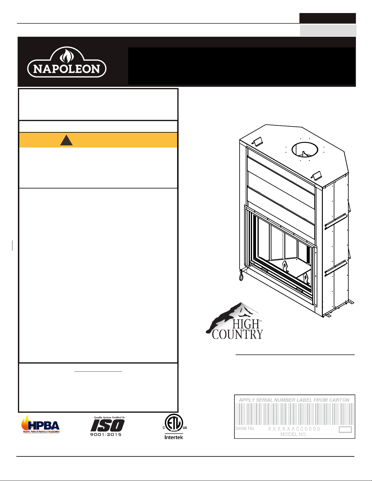
High Country™ 7000 / 8000*
These appliances have been safety tested and listed by Intertek
Testing Services Ltd. as per the standards: ULC S610, UL 127 U.S.
*Only the NZ8000 is an EPA Low Mass Wood-burning Fireplace
Voluntary Program Phase 2 Emission Level Qualified model.
(MUST use title from Price Book)
Low Mass Fireplace
ADD ____ ILLUSTRATED
(NZ8000 illustrated)
ADD PRODUCT IMAGE
FOR INDOOR USE ONLY
ADD SAFETY STANDARD INFORMATION
& EPA QUALIFICATION (IF APPLICABLE)
IF INSTALLATION + OPERATION, ADD SERIAL
NUMBER LABEL HERE
IF SEPARATE MANUALS, ADD “PLACE
BARCODE LABEL ON THE OWNER’S MANUAL”
$10.00
W415-1676 / C / 07.23.18
Page 2
EN
all plastic bags, these are not toys and should be kept away from children and infants.
WARNING
!
WARNING
safety information
• This appliance is hot when operated and can
cause severe burns if contacted.
• Any changes or alterations to this appliance or
its controls can be dangerous and is prohibited.
• Do not operate appliance before reading and
understanding operating instructions. Failure
to operate appliance according to operating
instructions could cause fi re or injury.
• Before installing this appliance, contact the
local building or fi re authority and follow their
guidelines.
• This appliance must be installed by a qualifi ed installer. Never try to repair or replace any part of the
appliance unless instructions are given in this manual. All other work should be done by a trained
technician.
• Risk of burns. The appliance should be turned off and cooled before servicing.
• Do not operate without fully assembling all components. Do not install damaged, incomplete or substitute
components.
• Do not let the appliance become hot enough for any part to glow red.
• Risk of cuts and abrasions. Wear protective gloves, footwear and safety glasses during installation. Sheet
metal edges may be sharp.
• All wiring should be done by a qualifi ed electrician and shall be in compliance with local codes. in the
absence of local codes, use the current CSA22.1 Canadian Electric Code in Canada or the current
National Electric Code ANSI/NFPA No. 70 in the United States.
• If equipped, burning your appliance with the ash dump door ajar creates a fi re hazard that may result in
discolouration to the door, internal damage to the appliance or a house and/or chimney fi re.
• Do not connect this appliance to a chimney fl ue serving another appliance.
• Clothing or other fl ammable material should not be placed on or near the appliance. Objects placed in
front of the appliance must be kept a minimum of 48” (121.9cm) away from the front face of the appliance.
• Due to high temperatures, the appliance should be located out of traffi c and away from furniture and
draperies.
• Even after the appliance is off, it will remain hot for an extended period of time.
• Any safety screen or guard removed for servicing must be replaced prior to operating the appliance.
• Under no circumstances should this appliance be modifi ed.
• This appliance must not be connected to a chimney fl ue pipe servicing a separate solid fuel burning
appliance.
• Do not operate the appliance with the glass door removed, cracked or broken. Replacement of the glass
should be done by a licensed or qualifi ed service person.
• Do not strike or slam shut the appliance glass door.
• Only doors / optional fronts certifi ed with the appliance are to be installed on the appliance.
• If the appliance is not properly installed, a house fi re may result. Do not expose the appliance to the
elements (ex. rain, etc.) and keep the appliance dry at all times. Wet insulation will produce an odour when
the appliance is used.
• The chimney must be sound and free of cracks. Clean your chimney a minimum of twice a year and as
required.
• Children and adults should be alerted to the hazards of high surface temperature and should stay away to
avoid burns or clothing ignition.
• Young children should be carefully supervised when they are in the same room as the appliance.
Toddlers, young children and others may be susceptible to accidental contact burns. A physical barrier
is recommended if there are at risk individuals in the house. To restrict access to an appliance or stove,
install an adjustable safety gate to keep toddlers, young children and other at risk individuals out of the
room and away from hot surfaces.
• Ensure you have incorporated adequate safety measures to protect infants/toddlers from touching hot
• Check with your local hearth specialty dealer for safety screens and hearth guards to protect children from
• Keep the packaging material out of reach of children and dispose of the material in a safe manner. As with
surfaces.
hot surfaces. These screens and guards must be fastened to the fl oor.
!
HOT GLASS WILL
CAUSE BURNS.
DO NOT TOUCH GLASS
UNTIL COOLED.
NEVER ALLOW CHILDREN
TO TOUCH GLASS.
2
W415-1676 / C / 07.23.18
Page 3

• Do not let the appliance become hot enough for any part to glow red.
• Risk of cuts and abrasions. Wear protective gloves, footwear and safety glasses during installation. Sheet
metal edges may be sharp.
• All wiring should be done by a qualifi ed electrician and shall be in compliance with local codes. in the
absence of local codes, use the current CSA22.1 Canadian Electric Code in Canada or the current
National Electric Code ANSI/NFPA No. 70 in the United States.
• If equipped, burning your appliance with the ash dump door ajar creates a fi re hazard that may result in
discolouration to the door, internal damage to the appliance or a house and/or chimney fi re.
• Do not connect this appliance to a chimney fl ue serving another appliance.
• Clothing or other fl ammable material should not be placed on or near the appliance. Objects placed in
front of the appliance must be kept a minimum of 48” (121.9cm) away from the front face of the appliance.
• Due to high temperatures, the appliance should be located out of traffi c and away from furniture and
draperies.
• Even after the appliance is off, it will remain hot for an extended period of time.
• Any safety screen or guard removed for servicing must be replaced prior to operating the appliance.
• Under no circumstances should this appliance be modifi ed.
• This appliance must not be connected to a chimney fl ue pipe servicing a separate solid fuel burning
appliance.
• Do not operate the appliance with the glass door removed, cracked or broken. Replacement of the glass
should be done by a licensed or qualifi ed service person.
• Do not strike or slam shut the appliance glass door.
• Only doors / optional fronts certifi ed with the appliance are to be installed on the appliance.
• If the appliance is not properly installed, a house fi re may result. Do not expose the appliance to the
elements (ex. rain, etc.) and keep the appliance dry at all times. Wet insulation will produce an odour when
the appliance is used.
• The chimney must be sound and free of cracks. Clean your chimney a minimum of twice a year and as
required.
• Children and adults should be alerted to the hazards of high surface temperature and should stay away to
avoid burns or clothing ignition.
• Young children should be carefully supervised when they are in the same room as the appliance.
Toddlers, young children and others may be susceptible to accidental contact burns. A physical barrier
is recommended if there are at risk individuals in the house. To restrict access to an appliance or stove,
install an adjustable safety gate to keep toddlers, young children and other at risk individuals out of the
room and away from hot surfaces.
• Ensure you have incorporated adequate safety measures to protect infants/toddlers from touching hot
surfaces.
• Check with your local hearth specialty dealer for safety screens and hearth guards to protect children from
hot surfaces. These screens and guards must be fastened to the fl oor.
• Keep the packaging material out of reach of children and dispose of the material in a safe manner. As with
all plastic bags, these are not toys and should be kept away from children and infants.
HOT GLASS WILL
CAUSE BURNS.
DO NOT TOUCH GLASS
UNTIL COOLED.
NEVER ALLOW CHILDREN
TO TOUCH GLASS.
!
WARNING
!
WARNING
!
WARNING
is inspected at least three times per heating season.
!
WARNING:
Electric
This product can expose you to chemicals including lead and lead compounds,
Gas, Wood
which are known to the State of California to cause cancer, and chemicals including BBP and
DEHP, which are known to the State of California to cause birth defects or other reproductive
harm. For more information, go to www.P65Warnings.ca.gov.
!
AVERTISSEMENT:
Ce produit peut vous exposer à des substances chimiques incluant le
plomb et les composés de plomb qui, selon l’État de Californie, causeraient le cancer, et des
substances chimiques incluant le BBP et DEHP qui, selon d’État de Californie, causeraient des
malformations congénitales ou autres dangers pour la reproduction.
Pour de plus amples renseignements, visitez le www.P65Warnings.ca.gov.
• Do not start a fi re with chemicals or fl uids such as gasoline, engine oil, etc.
• Your appliance requires periodic maintenance and cleaning. Failure to maintain your appliance may lead to smoke
spillage in your home.
• Ashes must be disposed in a metal container with a tight lid and placed on a non-combustible surface well
away from the home or structure until completely cool.
• Ensure clearances to combustibles are maintained when building a mantel or shelves above the appliance.
Elevated temperatures on the wall or in the air above the appliance can cause melting, discolouration or damage
to decorations, a T.V. or other electronic components.
For wood appliances:
• Lower emissions generally result when burning air dried seasoned hardwoods, as compared to softwoods
or too green or freshly cut hardwoods. Burning wet unseasoned wood can cause excessive creosote
accumulation. When this is ignited it can cause a chimney fi re that may result in a serious house fi re.
• This appliance is designed to burn natural wood only. Do not burn trash or garbage, lawn clippings /
waste, rubber, waste petroleum products, paints or paint thinners / solvents, plastic, materials containing
asbestos, construction debris, railroad ties or treated wood, manure or animal remains, salt water driftwood
or salted materials, unseasoned wood, coal, charcoal, coloured paper, gift wrapping, cardboard, plywood or
particleboard. Burning these materials may result in release of toxic fumes or render the appliance ineffective
and cause smoke.
• Burn wood directly on the fi rebricks. Do not elevate grate or otherwise raise the fi re.
• Do not store wood within appliance installation clearances or within the space required for re-fueling and
ash removal.
• If equipped, the catalyst must be installed and in good working order. It is recommended that the catalyst
!
WARNING:
which are known to the State of California to cause cancer, and chemicals including carbon
monoxide, which are known to the State of California to cause birth defects or other reproductive harm. For more information, go to www.P65Warnings.ca.gov.
This product can expose you to chemicals including lead and lead compounds,
safety information
EN
W415-1676 / C / 07.23.18
3
Page 4

EN
table of contents
1.0 dimensions 5
2.0 general information 6
2.1 general instructions 7
2.2 features 8
2.3 this appliance 8
2.4 packing list 8
2.5 rating plate information 9
3.0 installation planning 10
3.1 location and clearances 10
3.1.1 ventilation openings 11
3.2 outside combustion air 11
3.2.1 outside combustion air operation 12
3.3 floor protection / ember strip and hearth
extensions 13
3.3.1 hearth extension 14
3.3.2 hearth examples 15
3.3.3 flue damper operation 16
4.0 installation 17
4.1 chimney 17
4.2 typical chimney installation 18
4.3 adding chimney sections 19
4.4 offset chimney installation 20
4.5 installing flashing and storm collar 21
4.6 air cooled chimney installation 21
5.0 framing 22
5.1 finishing material 23
5.2 minimum clearance to combustibles 24
5.3 minimum enclosure clearances 24
5.4 minimum mantel clearances 25
6.0 operation and adjustments 26
6.1 door & screen operation 26
6.2 door level adjustment 27
6.3 door glass replacement 29
6.4 screen replacement 30
6.5 balance weight adjustment 31
6.6 firebrick installation 32
6.7 smoke chamber insulation panel
replacement 33
7.0 selecting wood 34
8.0 operation 35
8.1 operating sounds and smells 35
8.2 starting a fire 36
8.3 fire extinguishers / smoke dectectors &
carbon monoxide detectors 36
8.4 starting a fire (damper open) 37
8.5 smoking 38
8.6 reloading the appliance 38
9.0 maintenance 39
9.1 ash removal procedures 39
9.2 creosote formation and removal 39
9.3 run-away or chimney fire 39
9.4 chimney cleaning 40
9.5 care of glass 40
10.0 replacement parts 41
10.1 NZ7000 overview 42
10.2 NZ7000 accessories 43
10.3 NZ8000 overview 44
10.4 NZ8000 accessories 45
11.0 troubleshooting 46
12.0 warranty 47
4
note:
Changes, other than editorial, are denoted by a vertical line in the margin
W415-1676 / C / 07.23.18
Page 5

NZ8000 ILLUSTRATED
**
**
**
**
NZ8000 ILLUSTRÉ
**
**
**
**
1.0 dimensions
dimensions
13
61
"
16
1570mm
5
59
"
8
1514mm
3
57
"
8
1458mm
EN
13
80
"
16
2053mm
1
25
"
8
639mm
NZ7000 ILLUSTRATED
13
80
"
16
2053mm
1
34
"
4
870mm
**
**
**
5
78
16
1989mm
"
6"
152mm
1
16
30mm
31
791mm
3
"
1
"
8
5
30
"
16
770mm
1
31
"
2
800mm
****
3
1
"
5
78
16
1989mm
16
31mm
"
1
40
"
4
1023mm
[ 305mm ]
12"
[ 305mm ]
12"
46
1178mm
13
61
16
1570mm
59
1514mm
57
1458mm
46
1178mm
11
16
"
16
425mm
3
"
8
"
5
"
8
3
"
8
11
16
"
16
425mm
3
"
8
NZ8000 ILLUSTRATED
6"
152mm
NO SCREWS IN THIS AREA
SCREWS MUST NOT PENETRATE MORE THAN
1/2" (12.7mm) IN LENGTH IN THIS AREA
30
16
770mm
31
800mm
5
"
1
"
2
FACEPLATE
W415-1676 / C / 07.23.18
5
Page 6
EN
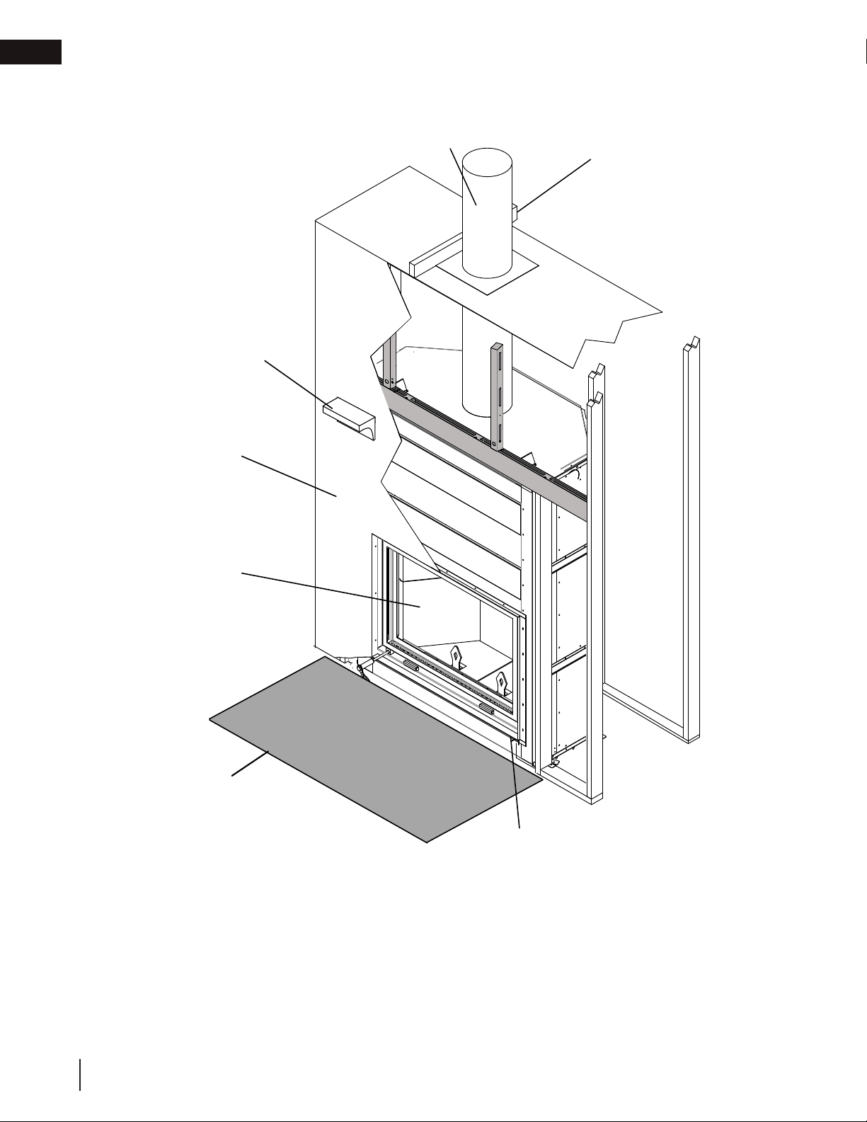
Hearth, see “hearth
extension” section
Rating plate, see “rating
plate information”
section
Firebrick, see “firebrick
installation” section
Framing, see “framing”
section
Chimney, see “chimney
installation” section
Mantel, see “minimum mantel
clearances” section
Finishing, see “finishing”
section
general information
2.0 general information
6
W415-1676 / C / 07.23.18
Page 7
general information
2.1 general instructions
WARNING
!
• Before installing this appliance, contact the local building or fire authority and follow their guidelines.
• This appliance must be installed by a qualified installer. Follow the installation directions. Do not operate
without fully assembling all components.
• If this appliance is not properly installed, a house fire may result.
• Do not expose the appliance to the elements (ex. rain, etc.) and keep the appliance dry at all times. Wet
insulation will produce an odour when the appliance is used.
• This appliance is hot when operated and can cause severe burns if contacted. Children and pets must be
kept from touching the appliance when it is hot. Contact your local authorized dealer/distributor for safety
screens that may be available for this product.
• Combustible material such as firewood, wet clothing, etc. placed too close can catch fire. Objects placed
in front of the appliance must be kept a minimum of 48” (121.9cm) from the front of the appliance.
• All wiring should be done by a qualified electrician and shall be in compliance with local codes and with
the National Electric Code ANSI/NFPA NO. 70-Current (in the United States), or with the current CSA
C22.1 Canadian Electric Code (in Canada).
• This appliance and its components are designed to be installed and operated as a system. Any alteration
to or substitution for items in this system, unless allowed by these installation instructions, will void the
OMNI listing and may void the product warranty. It may also create a hazardous installation. Read through
these instructions thoroughly before starting your installation and follow them carefully throughout your
project.
note:
It is recommended to test the listed
components below before installation:
• Doors
• Balance weights
• Louvre for air intake
• Flue damper
All components should be in good operating
condition before the appliance is installed.
3
EN
4
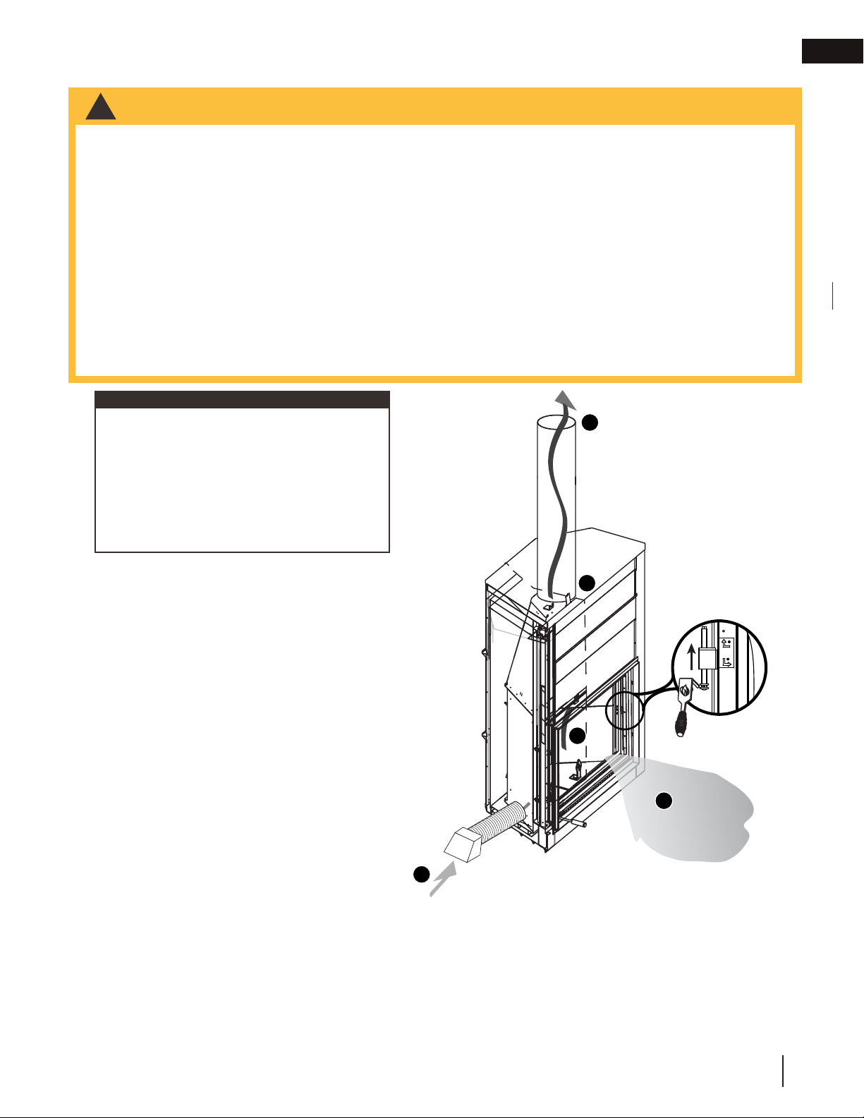
1. Combustion air is brought into the appliance
through the slots and around the glass door
or through the screen.
OPEN
CLOSED
2. Outside air is controlled with a damper to
supplement indoor air. The damper can only
be adjusted to be fully closed or fully open.
OPEN
3. Inside the firebox, combustion takes place
3
and exhausts out the chimney.
4. The appliance includes a flue damper at the
base of the chimney which shall be closed
1
when the appliance is not in use to prevent
cold air entering the home. See "firebrick
installation and damper operation" section.
2
The location of windows and doors, as well as the traffic flow in the room where the appliance is to be located should
be considered. If possible, choose a location where the chimney will pass through the house without cutting a floor or
roof joist.
W415-1676 / C / 07.23.18
7
Page 8

EN
general information
2.2 features
• Depending on the loading method and size of log,
maximum length of 32" (81.3cm).
• Large glass door for maximum visibility.
• Fully refractory lined firebox.
• Closable outside air damper.
• Closable flue damper.
• Shipping weight 1150lbs (521kg).
• Flue outlet diameter 12" (30.5cm).
• Max fuel load 60lbs (27kg).
• Max fuel height, halfway or top of the first firebrick.
• Safety tested to: ULC S610 and UL 127.
• Emissions tested to: ASTM E2515 and ASTM
E2558 for U.S. EPA Low Mass Wood-burning
Fireplace voluntary program phase 2 emissions
level (NZ8000 only).
2.3 this appliance
This appliance is a decorative product and not intended as a primary source of heat.
Approximate heating capacity up to 1,000 square feet (92 square meters).
WARNING
!
• Do not let the appliance become hot enough for any part to glow red.
2.4 packing list
Shipped with appliance:
Installation manual
Ember strip
Flue damper tool
THE NZ8000 HAS BEEN EPA QUALIFIED.
Do not use makeshift compromises during installation.
Do not block or restrict air, grille or louvre openings! Do
not add a hood.
Burning your appliance with the door open or ajar
creates a fire hazard that may result in a house and/or
chimney fire.
All venting connections must be in compliance with the chimney manufacturers installation instructions.
Clearances referred to throughout this manual are the minimum requirements.
Your appliance must be installed in accordance with all national and local building code standards and
the standard of Chimney and Appliances, Vents and Solid Fuel Burning Appliances NFPA #211. Consult
the authority having jurisdiction (such as municipal building department, fire department, fire prevention
bureau, etc.) to determine the need to obtain a permit. If you are in doubt about the proper installation for
your situation, contact your dealer or local building or fire official. The manufacturer does not guarantee
that this appliance and its options will completely heat your entire home.
Expansion / contraction noises during heating up and cooling down cycles are normal and to be expected.
It is recommended that in all cases, the appliance be secured to the floor. Use the pallet packing brackets
to accomplish this.
8
W415-1676 / C / 07.23.18
Page 9

general information
CERTIFIED TO / CERTIFIÉ SELON: ULC-S610, UL-127
A
SAMPLE
2.5 rating plate information
Rating plate is located behind the faceplate and door guide system on the right.
This illustration is for reference only. Refer to the rating plate on the appliance for accurate information.
EN
RATING
PLATE
LOCATION
note:
The rating plate must remain with the
appliance at all times. It must not be
removed.
9700539 (WSL)
4001657 (NGZ)
4001658 (NAC)
4001659 (WUSA)
INSTALL AND USE ONLY IN ACCORDANCE WITH WOLF STEEL LTD. INSTALLATION INSTRUCTIONS
AND OWNER'S MANUAL. CONTACT LOCAL BUILDING OR FIRE OFFICIALS ABOUT RESTRICTIONS
AND INSTALLATION INSPECTION IN YOUR AREA. DO NOT CONNECT THIS UNIT TO A CHIMNEY
SERVING ANOTHER APPLIANCE.
POUR INSTALLATION ET UTILISATION CONFORMÉMENT AUX MANUEL WOLF STEEL LTD.
RENSEIGNEZ-VOUS AUPRÈS DES AUTORITÉS LOCALES DU BÂTIMENT OU DU SERVICE DES
INCENDIES AU SUJET DES RESTRICTIONS ET DES INSPECTIONS D'INSTALLATION DANS VOTRE
RÉGION. NE PAS RACCORDER À LA CHEMINÉE D'UN AUTRE APPAREIL.
Use Solid wood, processed solid fuel fire logs (or other specified type) fuel only. / Utilisez du bois massif,
transformés solides bûches de combustible (ou un autre type spécifié) combustible seulement.
*FOR MODEL NZ8000 ONLY /
*POUR LA MODÈLE NZ8000 SEULEMENT
QUALIFIED EPA PHASE 2 MODEL UNTIL AUGUST 2019/
QUALIFIÉ EPA PHASE 2 MODÈLE JUSQU'À AOÛT 2019
MANUFACTURE DATE / DATE DE FABRICATION
Jan./Jan.
WARNING:THIS APPLIANCE HAS NOT BEEN TESTED
WITH AN UNVENTED GAS LOG SET. TO REDUCE
RISK OF FIRE OR INJURY, DO NOT INSTALL AN
UNVENTED GAS LOG SET INTO APPLIANCE. /
AVERTISSEMENT: CET APPAREIL N'A PAS ÉTÉ TESTÉ
AVEC DES BÛCHES À GAZ. POUR RÉDUIRE LES
RISQUES D'INCENDIE OU DE BLESSURES, NE PAS
INSTALLER UN BÛCHES À GAZ DANS L’APPAREIL.
PREVENT CREOSOTE FIRE: INSPECT CHIMNEY AND CHIMNEY
CONNECTOR, IF APPLICABLE, TWICE MONTHLY AND CLEAN IF
NECESSARY. DO NOT OVERFIRE: IF EXTERIOR OF UNIT GLOWS RED, YOU
ARE OVERFIRING. KEEP FURNISHINGS AND OTHER COMBUSTIBLE
MATERIALS A CONSIDERABLE DISTANCE AWAY FROM APPLIANCE. TYPE
OF FUEL: SOLID WOOD ONLY. PRÉVENIR LES FEUX DE CREOSOTE:
INSPECTEZ LA CHEMINÉE OU LE RACCORD DE CHEMINÉE, SI
APPLICABLE, DEUX FOIS PAR MOIS ET NETTOYEZ SI NÉCESSAIRE. NE
SURCHAUFFEZ PAS: SI L'EXTÉRIEUR DE L'UNITE DEVIENT ROUGE, VOUS
SURCHAUFFEZ. GARDEZ LES MEUBLES ET AUTRES MATÉRIELS
COMUSTIBLES À UNE DISTANCE CONSIDÉRABLE DE L'APPAREIL DE
CHAUFFAGE. TYPE DE COMBUSTIBLE: SOLIDE BOIS SEULEMENT.
*This model meets the U.S. EPA Wood-burning Fireplace Program Phase 2 emission level. To minimize smoke, always
operate your fireplace in accordance with the manufacturer’s instructions found in the owner’s manual. Additional information
about EPA’s Program is available at www.epa.gov/burnwise/index.html / Ce modèle répond à la Cheminée programme de
phase de niveau 2 des émissions États-Unis EPA à bois. Pour minimiser la fumée, toujours fonctionner votre foyer
conformément aux instructions du fabricant figurant dans le manuel du propriétaire. Des renseignements supplémentaires sur
le programme de l'EPA est disponible à www.epa.gov/burnwise/index.html
2016
Apr/Avr. Jul/Juill. Oct/Oct.
May/Mai Aug/Août. Nov/Nov.
Feb./Fév.
Jun/Juin Sep/Sept. Dec/Déc.
Mar./Mars.
Do not use a fireplace insert or other products not specified for use with this product.
Ne utiliser pas un insert de cheminée ou d'autres produits non spécifiées pour l'utilisation avec ce produit.
SHIPPED WITH THE FIREPLACE:
INSTALLATION MANUAL
EMBER STRIP
ULC-S629, ULC-S604, ULC-S610 for Canada or UL-103HT, UL-103 for the United States.
MINIMUM CHIMNEY HEIGHT
(FROM TOP OF APPLIANCE)
MAXIMUM CHIMNEY HEIGHT 40 ft (12.1 m) FLUE COLLAR 12"ø
MAXIMUM OFFSET ANGLE 30º US - 45º CANADA MIN. CHIMNEY DIAMETER 10"ø
LIVRÉ AVEC LE FOYER:
MANUEL D'INSTRUCTIONS
PARE-BRAISES
ULC-S629, ULC-S604, ULC-S610 pour le Canada ou selon les normes UL-103HT, UL-103 pour les
HAUTEUR MINIMALE DE LA CHEMINÉE
(DE HAUT DE L’APPAREIL)
HAUTEUR MAXIMALE DE LA CHEMINÉE 40 pi (12,1 m) BUSE D'ÉVACUATION: 12"ø
ANGLE DE DÉVIATION MAXIMAL 30º US - 45º CANADA
2018
2017
COMPONENTS REQUIRED FOR INSTALLATION:
CHIMNEY REQUIREMENTS (see installation manual):
Chimney must be certified to one of the following standards:
Air cooled chimney: Use DuraVent DuraChimney II.
COMPOSANTS REQUIS POUR L'INSTALLATION:
EXIGENCES POUR LA CHEMINÉE (voir le manuel d'instructions)
La cheminée doit être certifiée selon l'une des normes suivantes :
Cheminée refroidie à l'air: Utilisez DuraVent DuraChimney II.
MODEL/ N° DE MODÈLE
NZ7000
LISTED FACTORY BUILT FIREPLACE /
FOYER PRÉFABRIQUÉ HOMOLOGUÉ
WARNING :
· For use with screen
or glass door fully
2019
closed. Replace
ceramic glass only
with ceramic glass
obtained from the
dealer and certified
for use with this
appliance.
· Not for use in a
Mobile Home.
12 ft (3.66m) MAXIMUM # OF ELBOWS 4
États-Unis.
12 pi (3,66m) # MAXIMAL DE COUDES: 4
IMPORTANT: BEFORE COMMENCING INSTALLATION, REFER TO THE
LABEL LOCATED BEHIND THE FACEPLATE AND TO THE
MANUFACTURER'S INSTALLATION INSTRUCTIONS PACKAGED
TOGETHER WITH THIS UNIT. THE INSTALLATION MUST BE APPROVED BY
THE AUTHORITY HAVING JURISDICTION. AVANT DE COMMENCER
L'INSTALLATION, RÉFEREZ-VOUS À L'ÉTIQUETTE QUI SE TROUVE
DERRIÈRE LA FAÇADE AINSI QU'AUX INSTRUCTIONS D'INSTALLATION
DU MANUFACTURIER FOURNIES AVEC L'APPAREIL. L'INSTALLATION
DOIT ÊTRE APPROUVÉE PAR L'AUTORITÉ COMPÉTENTE.
MODEL/ N° DE MODÈLE
NZ8000*
NZ8000 AVERAGE
EMISSION / ÉMISSION
MOYENNE 4.87 g/kg
CERTIFIED TO ASTM E2515, ASTM E2558/
CERTIFIÉ AUX ASTM E2515, ASTM E2558
LISTED FACTORY BUILT FIREPLACE.
PHASE 2 EMISSION LEVEL QUALIFIED.
LOW MASS WOOD BURNING FIREPLACE. /
FOYER PRÉFABRIQUÉ HOMOLOGUÉ. LS
PHASE 2 NIVEAU QUALIFIÉ D’ÉMISSION.
FOYERS AU BOIS À FAIBLE MASSE.
MODEL CERTIFICATION DATE / DATE DE
CERTIFICATION 08/03/16
AVERTISSEMENT:
· Pour une utilisation
avec l’écran ou la porte
complètement fermé.
Remplacer verre
céramique seulement
uniquement avec verre
céramique obtenue
auprès du concession-
naire et certifiés pour
une utilisation avec cet
appareil.
· Ne peut pas être
installé dans une maison
mobile.
NOT SHIPPED WITH THE FIREPLACE:
REFRACTORY BRICKS
NE LIVRÉ AVEC LE FOYER:
BRIQUE RÉFRACTAIRE
MIN. CHEMINEE DIAMÈTRE: 10"ø
24 NAPOLEON ROAD. BARRIE, ONTARIO L4M 0G8 CANADA
NZ7000 / NZ8000
W415-1676 / C / 07.23.18
W385-2168 / A
9
Page 10
EN
!
WARNING
3.0 installation planning
installation planning
• Wear gloves, protective footwear and safety glasses for protection.
• Carefully follow the instructions for assembly of the pipe and other parts needed to install the appliance.
Failure to do so may result in a fi re, especially if combustibles are too close to the appliance or chimney and air
spacers are blocked, preventing the free movement of cooling air.
• Do not draw outside air from garage spaces. Exhaust products of gasoline engines are hazardous. Do not
install outside air ducts such that the air may be drawn from attic spaces, basements or above the roofi ng
where other heating appliances or fans and chimneys exhaust or utilize air. These precautions will reduce the
possibility of appliance smoking or air fl ow reversal. The outside air inlet must remain clear of leaves, debris, ice
and/or snow. It must be unrestricted while appliance is in use to prevent room air starvation which can cause
smoke spillage and an inability to maintain a fi re. Smoke spillage can also set off smoke alarms.
• Negative pressure within your home may inadvertently affect your appliance.
• To prevent contact with sagging or loose insulation, the appliance must not be installed against vapour barriers
or exposed insulation. Localized overheating could occur and a fi re could result.
• Do not use makeshift compromises during installation. Do not block or restrict air, grille or louvre openings. Do
not add a hood.
• To prevent personal injury, keep hand tools in good condition, sharpen cutting edges and make sure tool
handles are secure.
• Always maintain the minimum air space required in the enclosure to prevent fi res.
• Check with local building offi cials for any permits required for installation of this appliance and notify your
insurance company prior to proceeding.
3.1 location and clearances
WARNING
!
• Do not install into any area having a height less than 8 feet (2.4m) (ceiling of enclosure to appliance
bottom, excluding hearth height).
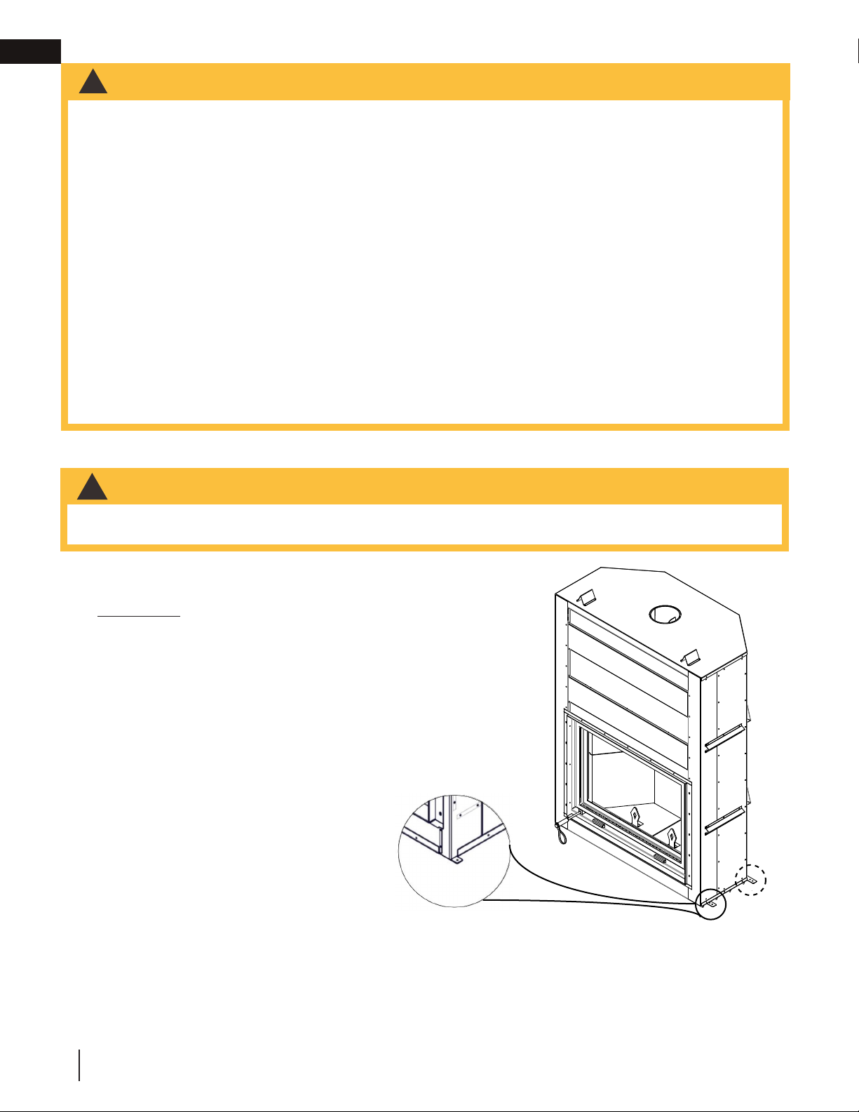
IMPORTANT
This appliance, fully dressed, weighs 1400lbs
(635kg). Ensure there is adequate floor support
for the appliance, chimney and facing material.
Some material could weigh hundreds of pounds.
We recommend that the appliance be
secured to the floor in all cases.
Using the door opening as a datum, level
the appliance by shimming underneath the
appliance. Bend the four securing tabs (located
on the front and back corners), and secure the
appliance to the floor.
Securing Tabs
x4
10
W415-1676 / C / 07.23.18
Page 11

installation planning
DIP
LOOP
OR
3.1.1 ventilation openings
It is recommended to provide air circulation within the enclosure by installing ventilation grilles (minimum openings
of 40 sq. inches (0.03 sq. meters) at both floor and ceiling levels of the enclosure). These grilles must not restrict
the flow of heat by more than 25%. Do not install into any area having a height less than 8 ft (2.4m) (ceiling of
enclosure to appliance bottom, excluding hearth height).
3.2 outside combustion air
It is recommended to install outside air to the appliance as this will help to prevent any smoke entering the living
space in homes that experience negative pressures. Check with local authorities having jurisdiction in your area,
as installing outside air to the appliance may be mandatory.
Insulating the intake liner is recommended in colder climates to prevent condensation from occurring.
It is recommended that a dip or loop is put into the duct creating a cold air trap in order to prevent cold air from
flowing into the room when the appliance is not being operated (see illustration below).
The NZ7000 and NZ8000 take outside air directly into the appliance through the opening on the left side.
The fresh air inlet duct and hood must be installed lower than the firebox. Secure and seal the intake liner to the
collar using 3 sheet metal screws, and high temperature sealant.
EN
The duct inlet must be located so they cannot be
blocked (i.e. snowdrifts). 12" (30.5cm) above grade
is recommended. Make a 4 ½" (114mm) inch
hole to suit in an outside wall of the house. From
outside, place the fresh air hood into the hole,
open side down. Seal with caulking and secure.
W415-1676 / C / 07.23.18
11
Page 12

EN
installation planning
3.2.1 outside combustion air operation
The outside combustion air control is located on the left hand side of the appliance directly behind the glass door
guide rail. (FIG. 1)
Before lighting the appliance, ensure the outside combustion air control is open by pulling the lever towards the
front of the appliance.
Before closing the outside combustion air control, allow the appliance to cool completely. To close, push lever in
towards the appliance.
OPEN
CLOSE
CLOSE
OPEN
FIG. 1
12
W415-1676 / C / 07.23.18
Page 13

installation planning
EMBER STRIP
(See “HEARTH
EXAMPLES” Section)
3.3 floor protection / ember strip and hearth extensions
WARNING
!
• Hearth extensions are to be installed only as described to prevent high temperatures from occurring on
concealed combustible materials. Hearth ember strips prevent burning or hot particles from inadvertently
falling directly on combustible surfaces in the event the building should settle and disturb the original
construction.
An acceptable 70" (177.8cm) x 20" (50.8cm) non-combustible (ie: brick, stone or ceramic tile) hearth extension
must be installed. Hearth must extend 20" (50.8cm) in front of the faceplate. Hearth must extend a minimum of
12" (30.5cm) to both sides of the appliance door opening. See local building codes for more detailed dimensions.
The hearth must extend a minimum 20" (50.8cm) in front of the appliance although if raised a minimum of 6 1/2"
(165mm) the 20" (50.8cm) may be reduced to a minimum of 18" (45.7cm).
The hearth must be a minimum of 1" (25mm) thick cement board (or equivalent)
plus ¼" (6.4mm) ceramic tile.
Ensure that the gap between the appliance and a non-combustible hearth
extension is sealed with sand/cement grout or covered with
an ember strip (or both) to prevent sparks and embers from falling
into this area.
Raised hearths must be constructed of non-combustible materials such as
cement blocks or bricks.
EN
While the appliance can be installed directly on the floor (using the ember
strip), a non-combustible hearth extension is required in front of the
appliance, that must not be built higher than the bottom of the appliance
faceplate. It may therefore be advisable to build the appliance on a raised
platform.
A raised hearth together with the appliance built on a raised platform is
recommended for easier wood loading and fire viewing.
W415-1676 / C / 07.23.18
13
Page 14

EN
EMBER STRIP
installation planning
3.3.1 hearth extension
12"
(30.5cm)
70 3/8"
(178.7cm)
46 3/8"
(117.7 cm)
20" (50.8cm)
EMBER STRIP
(Provided)
1
/2"
6
(165mm)
(178.7cm)
70 3/8"
20" (50.8cm)
An acceptable 70" (177.8cm) x 20" (50.8cm) non-combustible (ie:
brick, stone or ceramic tile) hearth extension must be installed.
Hearth must extend 20" (50.8cm) in front of the faceplate. Hearth
must extend a minimum of 12" (30.5cm) to both sides of the
appliance [70" (177.8cm)]. See local building codes for more detailed
dimensions.
Hearth must be a minimum of 1" (25mm) thick cement board (or
equivalent) plus ¼" (6.4mm) ceramic tile.
Ensure that the gap between the appliance and a combustible hearth
extension is sealed with sand/cement grout or covered with a metal
strip (or both) to prevent sparks and embers from falling into this area.
HEARTH EXTENSION
Elevated hearths must be constructed of noncombustible materials
such as cement blocks or bricks.
While the appliance can be installed directly on the floor (using the
ember strip), a non-combustible hearth extension is required in front
of the appliance, that must not be built higher than the bottom of the
appliance faceplate. It may therefore be advisable to build the appliance on a raised platform.
Hearths raised minimum 6 ½" (165mm) must extend a minimum of 18" (45.7cm).
SEE HEARTH
EXAMPLES
A raised hearth together with the appliance built on a raised platform is recommended for easier wood loading
and fire viewing.
14
W415-1676 / C / 07.23.18
Page 15

3.3.2 hearth examples
installation planning
EN
FLUSH HEARTH
MIN. 1/4” (6.4mm)
TILE OR MARBLE
COMBUSTIBLE FLOOR
RAISED HEARTH
COMBUSTIBLE FLOOR
20” MIN.
(50.8cm)
MIN. 1” (25mm) CEMENT BOARD
20” MIN.
1
6
/
2
6”
(165mm)
(152mm)
”
(50.8cm)
NON-COMBUSTIBLE MATERIALS
SUCH AS CEMENT
BLOCKS OR BRICKS
FACEPLATE
EMBER STRIP
FACEPLATE
EMBER STRIP
RAISED APPLIANCE
MIN. 1/4” (6.4mm)
TILE OR MARBLE
MIN. 1” (25mm)
CEMENT BOARD
PLYWOOD
RAISED HEARTH AND APPLIANCE
MIN. 1/4” (6.4mm)
MARBLE OR STONE
NON-COMBUSTIBLE
MATERIALS SUCH
AS CEMENT BLOCKS
OR BRICKS
PLYWOOD
20” MIN.
(50.8cm)
RAISED
APPLIANCE
COMBUSTIBLE FRAMING
20” MIN.
(50.8cm)
RAISED
APPLIANCE
COMBUSTIBLE FRAMING
FACEPLATE
EMBER STRIP
FACEPLATE
RAISED
HEARTH
EMBER STRIP
WARNING:
Ensure raised
platform is
designed to
support load of
fully loaded
appliance.
INCREASE
HEADER HEIGHT
THIS DIMENSION
See “Framing” section
WARNING:
Ensure raised
platform is
designed to
support load of
fully loaded
appliance.
INCREASE
HEADER HEIGHT
THIS DIMENSION
See “Framing” section
W415-1676 / C / 07.23.18
15
Page 16

EN
OPEN
CLOSED
installation planning
3.3.3 flue damper operation
OPEN
OPEN
CLOSED
To close the damper, pull the damper control rod down and
push it to the right.
To open the damper, push the damper control rod to the left
side and release.
CLOSED
note:
The damper must be in the “open” position when burning.
note:
If the damper becomes unthreaded, it will remain in the “open” position.
note:
If the damper does not operate properly, do not proceed with chimney installation. The damper operation
should be thoroughly checked before the chimney is installed.
16
W415-1676 / C / 07.23.18
Page 17

4.0 installation
WARNING
!
• Never install a single wall slip section or smoke pipe in a chase structure. The higher temperature of this single
wall pipe may radiate sufficient heat to combustible chase materials to cause a fire.
• To avoid danger of fire, all instructions must be strictly followed, including the provision of air space clearance
between chimney system and enclosure. To protect against the effects of corrosion on those parts exposed
to the weather.
• Maintain a minimum 2” (51mm) air clearance to all parts of the chimney system at all times. Failure to maintain
this 2” (51mm) air clearance will cause a structure fire.
• Detailed instructions for installation of the storm collar and termination cap are supplied by the manufacturer
and are packaged with these parts.
• Firestop spacers must be used whenever the chimney penetrates a ceiling/floor area.
• The chimney must be sound and free of cracks. Clean your chimney a minimum of twice a year and as
required.
• Always seal penetrations with temperature rated sealing products.
• Installation of a combustible chase enclosure above the roof is permissible if done in accordance with the
chimney manufacturer’s installation instructions.
installation
4.1 chimney
note:
All venting connections must be in compliance with the chimney manufacturer’s installation instructions.
This appliance was tested to CAN/ULC S610 and UL 127 Factory Built Fireplace Standards. This appliance has
met the test criteria for Zero Clearance Installation to Combustible Surfaces and Certified to burn firewood only.
Any chimney 10” (254mm) or 12” (30.5cm) diameter listed to CAN/ULC S610 for Canada or UL127 for the United
States or to the following standards; CAN/ULC-S604 and CAN/ULC-S629 for Canada or UL-103 or UL-103HT for
the United States may be installed.
Installation of all types of factory-built chimney systems is to be in accordance with the chimney manufacturers
installation instructions. An appropriate chimney manufacturers anchor base plate and anchor base plate gasket
is required in order to initiate their system. Use the high temperature gasket, supplied, to seal between the anchor
plate and the appliance top. Air cooled chimney systems are not
recommended in colder climates.
Chimney sections must be adequately secured one to the other to
ensure they do not separate. For complete installation instructions,
refer to instructions provided with the manufactured chimney system.
A chimney venting the appliance shall not vent any other appliance.
The minimum overall chimney height from the top of the appliance is
15ft (4.6m). The maximum overall chimney height from the top of the
appliance is 34ft (10.4m).
Factory-built chimney systems for use in dwellings constructed for
three or more families must be enclosed above the room in which the
appliance is located. This enclosure must have a fire resistance rating equal to or greater than that of the floor or
roof assembly through which they pass.
ANCHOR PLATE FOR A FACTORY
ANCHOR PLATE
ANCHOR PLATE GASKET
APPLIANCE TOP
BUILT CHIMNEY
EN
The chimney should not be built with an offset angle in excess of 45° in Canada and 30° in USA.
Ensure that minimum clearances are maintained.
Portions of the chimney that extend through accessible spaces must always be encased to avoid personal
contact with the chimney and thereby avoid damage to the chimney.
The chimney must be supported at a maximum of 20ft (6.1m) intervals. Every 20 ft (6.1m) of chimney can weigh
up to approximately 200lbs (90.7kg). When using a 10" chimney, center anchor plate to appliance flue outlet.
note:
Masonry chimney installs are not permitted.
W415-1676 / C / 07.23.18
17
Page 18

EN
Joist Framing
note:
installation
4.2 typical chimney installation
(10" or 12" Solid Packed or Air Cooled Chimney)
STORM COLLAR
ROOF FLASHING
ATTIC INSULATION
SHIELD
RAIN CAP
(4.6m)
MINIMUM
(10.4m)
MAXIMUM
15 FT
34 FT
STORM COLLAR
ROOF FLASHING
ATTIC INSULATION
SHIELD
OFFSET
SUPPORT
RAIN CAP
MINIMUM
(10.4m)
MAXIMUM
FIRESTOP
12” (30.5cm)
ATTIC INSULATION
15 FT
(4.6m)
34 FT
MIN*
STORM COLLAR
ROOF FLASHING
SHIELD
CEILING RADIATION
RAIN CAP
SHIELD
OFFSET
SUPPORT
FIRESTOP
STRAIGHT CHIMNEY SINGLE OFF-SET CHIMNEY DOUBLE OFF-SET CHIMNEY
* The first flue offset closest to the top of the appliance must be a
minimum distance of 12” (30.5cm) from the top of the appliance.
A. Move the appliance into position. Try to center the exhaust
flue of the appliance, midpoint between two joists to prevent
having to cut them. Use a plumb bob to line up the centre.
B. Cut and frame an opening in the ceiling to provide a
HEADERS
minimum clearance of 2” (50.8mm) between the outside of
the chimney and any combustible material. DO NOT FILL
THIS SPACE WITH ANY TYPE OF MATERIAL! Nail headers
between the joists for extra support. Firestop spacers must
be placed on each framed opening in any floor or ceiling
that the chimney passes through.
FIRESTOP SPACER UNDERSIDE OF JOIST
2" (50.8mm)
Min.
C. Hold a plumb bob from the underside of the roof to
determine where the opening in the roof should be.
Cut and frame the roof opening maintaining proper
2” (50.8mm) clearances.
30° or 45° offsets may be installed back to back.
2" (50.8mm)
Min.
Typical Joist Framing
2" (50.8mm)
Min.
Typical Roof
15 FT
(4.6m)
MINIMUM
34 FT
(10.4m)
MAXIMUM
12” (30.5cm)
MIN*
2" (50.8mm)
Min.
18
See "offsee chimney installation" section.
note:
39.12
When installing a 10" or 12" air cooled chimney, an NZAC10KT must be installed, see "air cooled chimney
installation" section.
W415-1676 / C / 07.23.18
Page 19

installation
4.3 adding chimney sections
Add chimney sections, according to the manufacturer’s installation instructions. If the chimney system passes
through an attic space, a rafter radiation shield or attic insulation shield is required. The chimney must extend at
least 3ft (0.9m) above its point of contact with the roof and at least 2ft (0.6m) higher than any wall, roof or building
within 10ft (3.1m). If the chimney extends more than 5ft (1.5m) above the roof, it must be secured using a roof
brace or guide wires. A raincap must be installed to avoid internal damage and corrosion.
LESS THAN
10FT (3m)
2 FT (0.6m)
3 FT (1m)
MIN
RIDGE
2 FT (0.6m) MIN
10 FT (3m)
TO NEAREST
ROOFLINE
MIN
3 FT (1m)
MIN
LESS THAN
10FT (3m)
EN
10 FT (3m)
OR MORE
FLAT ROOF
note:
This illustration is for wood appliances only.
Ceiling Joist
LIVING SPACE
Chimney must be
totally enclosed
when passing
through living space
with a minimum 2”
(51mm) clearance
to combustibles.
3 FT (1m)
MIN
3 FT (1m)
MIN
ATTIC SPACE
Chimney Lengths
Framed
Enclosure
2” (51mm)
clearance from
chimney to
combustible wall
2 FT (0.6m)
MIN
WALL
Floor, Ceiling Joist
W415-1676 / C / 07.23.18
19
Page 20

EN
WARNING
installation
4.4 offset chimney installation
!
• Chimney sections installed between an offset and return require structural support to reduce off-center
loading and to prevent chimney sections from separating at the chimney joists.
• The chimney should not be built with an offset angle in excess of 45° in Canada and 30° in USA. Do not
combine offset chimney components to exceed these angles.
The first flue offset closest to the top of the
appliance must be a minimum distance of
12" (30.5cm) from the top of the appliance.
Attach an elbow to the chimney section, angled
toward the offset. Secure according to chimney
manufacturer’s instructions. Chimney sections must
be adequately secured one to the other to ensure
they do not separate. To achieve the minimum
offset, attach and secure a second elbow. To
achieve longer offsets, you may install any available
length of chimney pipe between the elbows.
Supports must be used on the first vertical chimney
section after a return elbow.
Storm Collar
Roof Joist
Chimney Section
Elbow Support
Straps
Elbow
Rain Cap
Roof
Flashing
Attic Insulation
Shield
Elbow Support
Band
Elbow
Floor , Ceiling Joist
Firestop
20
W415-1676 / C / 07.23.18
If the offset length is more than 36” (91.4cm), an
intermediate support must be employed. To
achieve longer offsets, you may install any
available length of chimney pipe between the
elbows.The intermediate support must be used
in conjunction with an offset support.
Page 21

installation
AIR HOUSING
2
DURA CHIMNEY II SECTION
4” (102mm) LINER
DURAVENT 8 DCA - AP
STARTER COLLAR
4.5 installing flashing and storm collar
The following are generic installation instructions for installing the flashing around a chimney. Installation of all
types of factory-built chimney systems is to be in accordance with the chimney manufacturer’s installation
instructions. Remove the nails from the shingles above and to the sides of the chimney. Place the flashing over
the chimney pipe and slide underneath the sides and upper edge
of the shingles. Ensure that the chimney pipe is properly
centered within the flashing, giving a 3/4” (19.1mm) margin all
around. Fasten to the roof on the top and sides. DO NOT NAIL
through the lower portion of the flashing. Make weather-tight by
sealing with caulking. Where possible, cover the sides and top
edges of the flashing with roofing material. Apply waterproof
caulking, provided with the flashing, around the chimney, 1”
(25.4mm) above the top of the flashing and push the storm collar
down into the caulking. Insert a rain cap onto the top of the last
chimney section.
4.6 air cooled chimney installation
Any air cooled chimney 10" (254mm) or 12" (30.5cm)
in diameter listed to CAN/ULC-S604 for Canada or
UL-103 for the United States may be installed. Any air
cooled chimney selected for use MUST have provisions
to directly feed outside air to the corresponding anchor
plate via sealed housing; for example, the NZAC10KT
that has been developed specifically for the use with
10" DuraVent DuraChimney II.
(NZAC10KT)
RAIN CAP
CAULKING
STORM COLLAR
WEATHER
SEALANT
FLASHING
EN
1. Install the start collar using the gasket provided
over the flue and fasten to the top of the fireplace.
2. Slide the air housing onto the first section of the
chimney and secure the chimney to the starter
collar.
3. Slide the air housing down the chimney section
and secure housing to the top of the appliance.
4. Connect the outside air connection for the chimney.
note:
Air slots in the starter collar are to be completely
covered by the air housing
note:
Follow the chimney manufacturer’s instructions
for installing the chimney.
note:
Use 111KT outside air kit to connect to air
housing. Maximum length of 4” (101.5mm) liner
is 20’ (6m). If greater length is required then
increase the liner diameter to 6” (154.4mm).
DURAVENT 10DCA-
AP 10"/12" STARTER
COLLAR
note:
An air cooled chimney requires its own dedicated outside air supply with a minimum of 4” liner diameter. (Not
to be shared with appliance outside air).
W415-1676 / C / 07.23.18
21
Page 22

EN
30 9/16"
(77.6cm)**
81 1/4"
(206.4cm) *
96"
(243.8cm)
MIN.
60"
(152.4cm)
STEEL STUD
5.0 framing
framing
WARNING
!
• In order to avoid the possibility of exposed insulation or vapour barrier coming in contact with the appliance
body, it is recommended that the walls of the appliance enclosure be “finished” (i.e.: drywall/sheetrock), as
you would finish any other visible wall of a home. This will ensure that clearance to combustibles is maintained
within the cavity.
• Do not build shelves or cupboards into the area above the appliance.
• Objects placed in front of the appliance must be kept a minimum of 48” (121.9cm) away from the front face of
the appliance.
note:
Use metal studs wherever non-combustible facing is required.
* Allow for finished floor and hearth thickness when setting these dimensions.
** When constructing the enclosure allow for finishing material thickness and to maintain clearances.
22
W415-1676 / C / 07.23.18
Page 23

framing
NON-COMBUSTIBLE BOARD
COMBUSTIBLE
FACING AND WOOD
FRAMING MAY START
AT 8’ (2.4M) ABOVE
THE BASE OF THE
APPLIANCE.
FACE MUST HAVE A
MIN. 8’ (2.4M) HEIGHT
OF NON-COMBUSTIBLE
BOARD DEPENDING
UPON THE CEILING
HEIGHT
FACEPLATE
MIN. ENCLOSURE
CEILING HEIGHT 96”
(243.8CM).
USE METAL STUDS WHEREVER NON-COMBUSTIBLE
FACING IS REQUIRED
NON-COMBUSTIBLE
BOARD FROM THE SIDE
MEASURED FROM THE
SIDE OF THE FACEPLATE.
46 3/8"
(117.8cm)
MIN. 6"
(152mm)
*
5.1 finishing material
WARNING
!
• Screws used to fasten finishing materials to the face of the appliance above the guillotine screen and door
must not penetrate more than 1/2” (13mm) into the sheet metal front panels. Refer to the “dimensions”
section for specific requirements.
• Do not pack air spaces with insulation or other materials.
• Use only a non-combustible material to finish the face of the appliance. A non-combustible material such
as cement board is required for this purpose.
• Ventilation openings are mandatory for enclosures.
• Above 73 5/8” (187cm) combustible finishing materials may be used on the front face (measured appliance
from base of unit).
• Do not insulate around the appliance.
note:
Before you completely close up the enclosure, ensure the air control, flue damper and the door / screen
assemblies perform as intended.
EN
* 7 1/2" (190.5mm) is recommend to meet centre of slip studs.
W415-1676 / C / 07.23.18
23
Page 24

EN
framing
5.2 minimum clearance to combustibles
Framed Enclosure
Rear and Sides of the appliance - 0" (0mm) to stand-offs
Ceiling, enclosure or in front of appliance - 96" (243.8cm) from the base of the appliance
Chimney - 2" (51mm) (follow manufacturer's instructions)
5.3 minimum enclosure clearances
30 9/16"
(77.6cm)
24"
(61cm)
MIN
68 5/8"
(174cm)
60" (152.4cm)
97" (246.4cm)
30 9/16"
(77.6cm)
60"
(152.4cm)
24"
(61cm)
MIN
21" (53.3cm)
MIN
60" (152.4cm)
note:
When framing in the appliance, allow for
finishing material thickness.
24
* It is recommended to leave a minimum of 24" (61cm) of clearance to the sides of the
appliance to facilitate servicing the guillotine door operating systems; access to this space
will need to be considered.
W415-1676 / C / 07.23.18
Page 25

framing
!
WARNING
5.4 minimum mantel clearances
• Risk of fire. Maintain all specified air space clearances to combustibles. Failure to comply with these instructions
may cause a fire or cause the appliance to overheat. Ensure all clearances (i.e. back, side, top, vent, mantel,
front, etc.) are clearly maintained.
• When using paint or lacquer to finish the mantel, the paint or lacquer must be heat resistant to prevent
discolouration.
An optional combustible mantel must be a minimum of 12" (30.5cm) above the top of the faceplate and not to
extend more than 2" (51mm) from the surface. See chart below for further information.
A = 8" (203mm)
B= 6" (152mm)
C= 4" (102mm)
D= 2" (51mm)
A
B
C
D
E F G H
E = 12" (30.5cm)
F= 14" (35.6cm)
G= 16" (40.6cm)
H= 18" (45.7cm)
EN
TOP OF
FACEPLATE
(KEYSTONE)
I = NZ7000 31 1/8" (79.1cm)
I
I = NZ8000 40 1/4" (102.2cm)
W415-1676 / C / 07.23.18
25
Page 26

EN
!
WARNING
6.0 operation and adjustments
operation and adjustments
• Use only a non-combustible material to finish the face of the appliance. A non-combustible material such as
cement board is required for this purpose.
• Ventilation openings are recommended for all enclosures.
• On the front face, combustible finishing materials may be above 8' (2.4m).
• Do not insulate around the appliance.
6.1 door & screen operation
note:
The appliance should be operated with either the glass or screen door closed, other then when loading wood.
Insert tether into screen and glass door receiver bottom left corner to raise and lower the door. When not in use,
hang tether on tool set.
To swing open the glass door, lift the latch on the right side up and swing the door outward.
TETHER
note:
To prevent the rapid rise of the doors, since
they are balanced with counterweights, it is
recommended to secure the cable on the top
of the door frame when removing the door or
screen frames for service.
26
W415-1676 / C / 07.23.18
Page 27

6.2 door level adjustment
WARNING
!
• Do not use substitute materials.
• Glass may be hot; do not touch glass until cooled.
Door adjustment may be
necessary if door is not level.
operation and adjustments
EN
note:
The safety screen and glass door are equipped with the same adjustment mechanism. If necessary, follow
the same “door level adjustment” procedure for the safety screen and/or glass door.
note:
Door adjustment is strictly trial and error; you may need to perform this adjustment a few times until the
desired door angle is attained.
1
2
Lower the door and shim the corner that is
resting on the hearth approximately half the gap of
the opposing side.
Loosen top and bottom screws on the left side of
door frame. Pull the high side down to touch the
hearth.
W415-1676 / C / 07.23.18
27
Page 28

EN
operation and adjustments
3
Tighten the two screws on the side of the door
frame.
4
Ensure door is level and screws are secured. Re-
peat as necessary.
28
W415-1676 / C / 07.23.18
Page 29

operation and adjustments
6.3 door glass replacement
WARNING
!
• Do not use substitute materials.
• Glass may be hot; do not touch glass until cooled.
• Care must be taken when removing and disposing of any broken door glass or damaged components. Be sure
to vacuum up any broken glass from inside the appliance before operation.
• Do not strike, slam or scratch glass. Do not operate appliance with glass removed, cracked, broken or
scratched.
A. Lift the screen up into the appliance.
B. Lower the glass door down and unlatch. Swing
the glass door open.
C. Unscrew the top and bottom retainers inside door
frame. (FIG. 1)
D. Remove glass from door frame. (FIG. 2)
E. Center and apply gasket to the edge of glass.
Ensure gasket is a continuous loop around the
perimeter of the replacement glass. (FIG. 3)
F. Reinstall glass inside the door frame. (FIG. 4)
G. Reposition top and bottom retainers
using screws removed in Step C. Ensure
retainer is in position correctly. (FIG. 5)
FIG.1
EN
FIG.2
FIG.4
FIG.3
FIG.5
W415-1676 / C / 07.23.18
29
Page 30

EN
operation and adjustments
6.4 screen replacement
note:
Removing the screen will result in the screen immediately rising, use caution. It is recommended to have another
person assist in hold the screen door while the screen frame is being removed.
A. Insert the handle and lift the screen slightly up to remove the 2 screws on the bottom inside of the screen
frame. (FIG. 1)
B. Remove the 10 top and bottom screws and the 6 side screws. (FIG. 2)
C. Remove the screen from the frame and replace.
D. Reverse these steps to reinstall the screen frame onto the appliance.
E. If the screen door becomes unbalanced, refer to "balance weight adjustment" section.
FIG 2:FIG 1:
note:
Do not leave the door slightly open. Ensure your counter weights are balanced and the doors close properly
30
W415-1676 / C / 07.23.18
Page 31

operation and adjustments
6.5 balance weight adjustment
Balance weights have been added to this appliance to counter the weight of the guillotine at the rear of the
appliance. They stabilize the balance of the screen door and glass door movement.
If the glass door or screen door become unbalanced (falling or rising rapidly), it is important to adjust the balance
weight of the doors to ensure they perform properly.
BALANCE
WEIGHT
EN
The screen door balance weights are located on the main frame on the inside right of the screen frame. Remove
or add as required to balance.
BALANCE
WEIGHT
The glass door balance weights are located on the outer glass frame on the left side. Remove or add as required
to balance.
W415-1676 / C / 07.23.18
31
Page 32

EN
operation and adjustments
6.6 firebrick installation
WARNING
!
• Risk of fire! Operation of the appliance without the firebricks can result in excessive temperatures that will
damage the appliance, chimney and the surrounding enclosure.
note:
Ensure fibre panels set in behind brick are in good condition before installing firebrick. If fibre panels need to
be replaced, hold panels in position or secure with masking tape until firebrick is installed.
Proper Installation of Side Panels:
Side panels will have two distinct angles on either side of each panel. The shallow angle should face the outside of the
appliance. The steeper angle should face to the inside of the appliance and will match to the adjacent panel.
A. Tilt and install the right rear
firebrick against the wall.
D. Tilt the top right firebrick
and secure under the
retaining bracket.
B. Install the middle and left
rear firebricks.
E. Install the remaining top firebricks,
securing under the retaining
brackets. Install the andirons into the
bottom firebricks.
C. Install the bottom
firebricks to aid securing
the rear firebricks against
the wall.
32
W415-1676 / C / 07.23.18
Page 33

EN
Items may not appear exactly as illustrated.
4
5
7
NZ7000 OVERVIEW
9
6
1
2
5
4
1
2
10
Door Adjustment
replacement parts
42
10.1 NZ7000 overview
W415-1676 / C / 07.23.18
Page 34

replacement parts
(Fluted)
NZ7SBK
Andiron (X2)
Top, Left Side Fluted Brick Panel (NZ7FBK)
Top, Centre Fluted Brick Panel (NZ7FBK)
Top, Right Side Fluted Brick Panel (NZ7FBK)
Top, Left Side Brick Panel (NZ7SBK)
Top, Centre Brick Panel (NZ7SBK)
Top, Right Side Brick Panel (NZ7SBK)
EN
10.2 NZ7000 accessories
W415-1676 / C / 07.23.18
43
Page 35

EN
Stocked
Yes
6
9
10
1
3
4
5
6
1
3
7
replacement parts
10.3 NZ8000 overview
44
W415-1676 / C / 07.23.18
Page 36

Items may not appear exactly as illustrated.
Andiron (X2)
26
20
11
17
23
22
28
11
23
171420
9
19
25
NZ8TBK
3
26
(TRADITIONAL)
replacement parts
EN
10.4 NZ8000 accessories
(HERRING BONE) (SMOOTH)
W415-1676 / C / 07.23.18
45
 Loading...