

Page 1
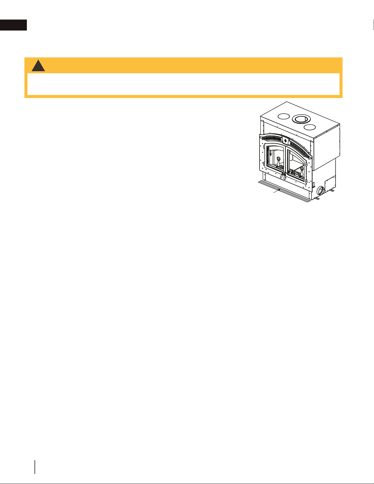
This wood appliance needs periodic inspection and repair. It is against United States federal regulations to operate this wood
appliance in a manner inconsistent with the operating instructions in this manual.
INSTALLATION AND
ADD MANUAL TITLE
OPERATION MANUAL
ENGLISH
FRENCH
PG. 51
INSTALLER:
Leave this manual with the appliance.
CONSUMER:
Retain this manual for future reference.
SAFETY INFORMATION
!
WARNING
If the information in these instructions are not followed exactly, a fi re
or explosion may result causing property damage, personal injury or
death. Please read the entire manual before you install and use your
appliance. This heeater has not been tested with an unvented gas log
set. To reduce risk of fi re or injury, do not install an unvented gas log
set into the heater.
- This heater can be very hot when burning.
- Combustible materials such as fi rewood, wet clothing, etc. placed
too close can catch fi re.
- Children and pets must be kept from touching the heater when it is
hot.
- The chimney must be sound and free of cracks. Before installing this
appliance, contact the local building or fi re authority and follow their
guidelines.
- Always operate this appliance with the door(s) or screen (where
applicable) tightly closed.
- Burn wood behind the log retainer directly on the fi rebricks.
- Do not use an elevated grate or otherwise raise the fi re.
- This appliance is designed to burn natural wood only. Higher
effi ciencies and lower emissions generally result when burning air
dried seasoned hardwoods, as compared to softwoods or to green
or freshly cut hardwoods.
- Do not start a fi re with chemicals or fl uids such as gasoline, engine
oil, etc.
- Do not burn trash or garbage, lawn clippings/waste, rubber,
waste petroleum products, paints or paint thinners/solvents, plastic,
materials containing asbestos, construction debris, railroad ties or
treated wood, manure or animal remains, salt water driftwood or
salted materials, unseasoned wood, coal, charcoal, coloured papeer,
cardboard, plywood or particleboard. Burning these materials may
result in release of toxic fumes or render the appliance ineffective and
cause smoke.
- Do not let the appliance become hot enough for any part to glow
red.
Wood Stoves ONLY
- At least 14 squares inches (90.3 square centimeters) of outside air
must be admitted to the room or directly to the appliance through a
4” (101.6mm) diameter pipe.
- KEEP THE STOVE TOP TEMPERATURE BELOW 700°F (371°C).
Attempts to achieve heat output rates that exceed design
specifications can result in steel distortion and damage.
CSA / OMNI
/ INTERTEK
LOGO
Wolf Steel Ltd., 24 Napoleon Rd., Barrie, ON, L4M 0G8 Canada / 103 Miller Drive, Crittenden, Kentucky, USA, 41030
Phone 1 (866) 820-8686 • www.napoleon.com • hearth@napoleon.com
Product Name / Code
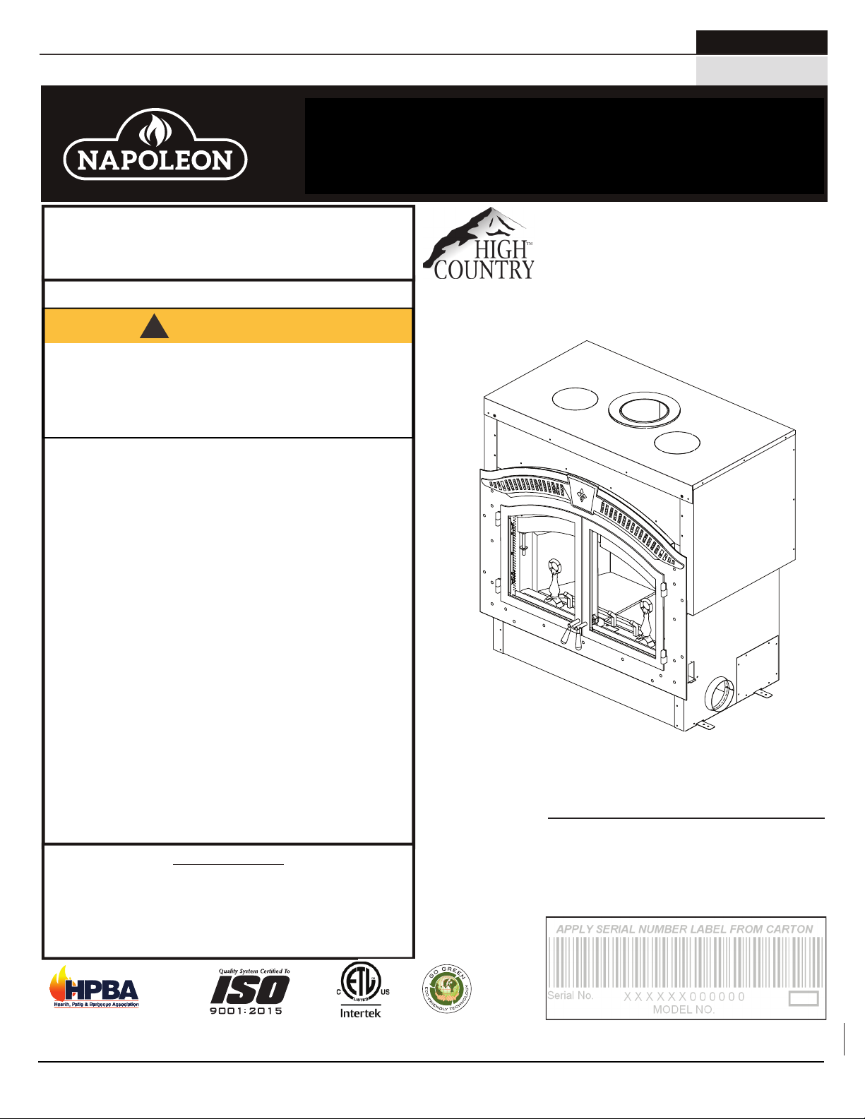
HIGH COUNTRY™ 6000
(MUST use title from Price Book)
Low Mass Appliance
ADD ____ ILLUSTRATED
(NZ6000-1 Illustrated)
ADD PRODUCT IMAGE
FOR INDOOR USE ONLY
THIS APPLIANCE HAS BEEN TESTED AND LISTED BY INTERTEK TESTING
ADD SAFETY STANDARD INFORMATION
SERVICES LTD. AS PER THE STANDARDS: ULC S610, UL 127 FOR
& EPA QUALIFICATION (IF APPLICABLE)
IF INSTALLATION + OPERATION, ADD SERIAL
NUMBER LABEL HERE
IF SEPARATE MANUALS, ADD “PLACE
BARCODE LABEL ON THE OWNER’S MANUAL”
FACTORY BUILT FIREPLACES.
$10.00
W415-1501 / E / 12.17.18
Page 2
EN
safety information
WARNING
!
• This appliance is hot when operated and can cause
severe burns if contacted.
• Any changes or alterations to this appliance or its
controls can be dangerous and is prohibited.
• Do not operate appliance before reading and
understanding operating instructions. Failure
to operate appliance according to operating
instructions could cause fi re or injury.
• Before installing this appliance, contact the local
building or fi re authority and follow their guidelines.
• This appliance must be installed by a qualifi ed
installer. Never try to repair or replace any part of the appliance unless instructions are given in this manual.
All other work should be done by a trained technician.
• Risk of burns. The appliance should be turned off and cooled before servicing.
• Do not operate without fully assembling all components. Do not install damaged, incomplete or substitute
components.
• Do not let the appliance become hot enough for any part to glow red.
• Risk of cuts and abrasions. Wear protective gloves, footwear and safety glasses during installation. Sheet
metal edges may be sharp.
• All wiring should be done by a qualifi ed electrician and shall be in compliance with local codes. in the
absence of local codes, use the current CSA22.1 Canadian Electric Code in Canada or the current
National Electric Code ANSI/NFPA No. 70 in the United States.
• If equipped, burning your appliance with the ash dump door ajar creates a fi re hazard that may result in
discolouration to the door, internal damage to the appliance or a house and/or chimney fi re.
• Do not connect this appliance to a chimney fl ue serving another appliance.
• Clothing or other fl ammable material should not be placed on or near the appliance. Objects placed in
front of the appliance must be kept a minimum of 48” (121.9cm) away from the front face of the appliance.
• Due to high temperatures, the appliance should be located out of traffi c and away from furniture and
draperies.
• Even after the appliance is off, it will remain hot for an extended period of time.
• Any safety screen or guard removed for servicing must be replaced prior to operating the appliance.
• Under no circumstances should this appliance be modifi ed.
• This appliance must not be connected to a chimney fl ue pipe servicing a separate solid fuel burning
appliance.
• Do not operate the appliance with the glass door removed, cracked or broken. Replacement of the glass
should be done by a licensed or qualifi ed service person.
• Do not strike or slam shut the appliance glass door.
• Only doors / optional fronts certifi ed with the appliance are to be installed on the appliance.
• If the appliance is not properly installed, a house fi re may result. Do not expose the appliance to the
elements (ex. rain, etc.) and keep the appliance dry at all times. Wet insulation will produce an odour when
the appliance is used.
• The chimney must be sound and free of cracks. Clean your chimney a minimum of twice a year and as
required.
• Children and adults should be alerted to the hazards of high surface temperature and should stay away to
avoid burns or clothing ignition.
• Young children should be carefully supervised when they are in the same room as the appliance.
Toddlers, young children and others may be susceptible to accidental contact burns. A physical barrier
is recommended if there are at risk individuals in the house. To restrict access to an appliance or stove,
install an adjustable safety gate to keep toddlers, young children and other at risk individuals out of the
room and away from hot surfaces.
• Ensure you have incorporated adequate safety measures to protect infants/toddlers from touching hot
surfaces.
• Check with your local hearth specialty dealer for safety screens and hearth guards to protect children from
hot surfaces. These screens and guards must be fastened to the fl oor.
• Keep the packaging material out of reach of children and dispose of the material in a safe manner. As with
all plastic bags, these are not toys and should be kept away from children and infants.
• Do not start a fi re with chemicals or fl uids such as gasoline, engine oil, etc.
2
W415-1501 / E / 12.17.18
!
WARNING
HOT GLASS WILL
CAUSE BURNS.
DO NOT TOUCH GLASS
UNTIL COOLED.
NEVER ALLOW CHILDREN
TO TOUCH GLASS.
Page 3
safety information
WARNING
!
• Your appliance requires periodic maintenance and cleaning. Failure to maintain your appliance may lead to smoke
spillage in your home.
• Ashes must be disposed in a metal container with a tight lid and placed on a non-combustible surface well
away from the home or structure until completely cool.
• Ensure clearances to combustibles are maintained when building a mantel or shelves above the appliance.
Elevated temperatures on the wall or in the air above the appliance can cause melting, discolouration or damage
to decorations, a TV or other electronic components.
!
WARNING:
which are known to the State of California to cause cancer, and chemicals including carbon
Add California Prop 65 warning
monoxide, which are known to the State of California to cause birth defects or other reproductive harm. For more information, go to www.P65Warnings.ca.gov.
For wood appliances:
• Lower emissions generally result when burning air dried seasoned hardwoods, as compared to softwoods
or too green or freshly cut hardwoods. Burning wet unseasoned wood can cause excessive creosote
accumulation. When this is ignited it can cause a chimney fi re that may result in a serious house fi re.
• This appliance is designed to burn natural wood only. Do not burn trash or garbage, lawn clippings /
waste, rubber, waste petroleum products, paints or paint thinners / solvents, plastic, materials containing
asbestos, construction debris, railroad ties or treated wood, manure or animal remains, salt water driftwood
or salted materials, unseasoned wood, coal, charcoal, coloured paper, gift wrapping, cardboard, plywood or
particleboard. Burning these materials may result in release of toxic fumes or render the appliance ineffective
and cause smoke.
• Burn wood directly on the fi rebricks. Do not elevate grate or otherwise raise the fi re.
• Do not store wood within appliance installation clearances or within the space required for re-fueling and
ash removal.
• If equipped, the catalyst must be installed and in good working order. It is recommended that the catalyst
is inspected at least three times per heating season.
This product can expose you to chemicals including lead and lead compounds,
EN
Do not use makeshift compromises during installation.
Do not block or restrict air, grille or louvre openings! Do
not add a hood.
Burning your appliance with the door open or ajar creates a fi re hazard that may result in a house and/or
chimney fi re.
All venting connections must be in compliance with the chimney manufacturers installation instructions.
Clearances referred to throughout this manual are the minimum requirements.
Your appliance must be installed in accordance with all national and local building code standards and
the standard of Chimney and Appliances, Vents and Solid Fuel Burning Appliances NFPA #211. Consult
the authority having jurisdiction (such as municipal building department, fi re department, fi re prevention
bureau, etc.) to determine the need to obtain a permit. If you are in doubt about the proper installation for
your situation, contact your dealer or local building or fi re offi cial. The manufacturer does not guarantee
that this appliance and its options will completely heat your entire home.
Expansion / contraction noises during heating up and cooling down cycles are normal and to be expected.
It is recommended that in all cases, the appliance be secured to the fl oor. Use the pallet packing brackets
to accomplish this.
W415-1501 / E / 12.17.18
3
Page 4

EN
table of contents
1.0 dimensions 5
2.0 general information 6
2.1 general instructions 6
2.2 features 7
2.3 this cordwood fuel appliance 7
2.4 electrical specifi cations 7
2.5 packing list 7
2.6 rating plate information 8
3.0 installation overview 9
4.0 installation planning 10
4.1 location and clearances 10
4.2 ventilation openings 11
4.3 outside combustion air 11
4.4 fl oor protection 12
4.4.1 ember strip and hearth extensions 12
4.4.2 hearth extension 13
4.4.3 hearth examples 14
5.0 installation 15
5.1 chimney 15
5.2 typical chimney installation 16
5.3 adding chimney sections 17
5.4 offset chimney installation 18
5.5 installing fl ashing and storm collar 19
5.6 connection to a masonry chimney 19
5.7 air cooled chimney installation 20
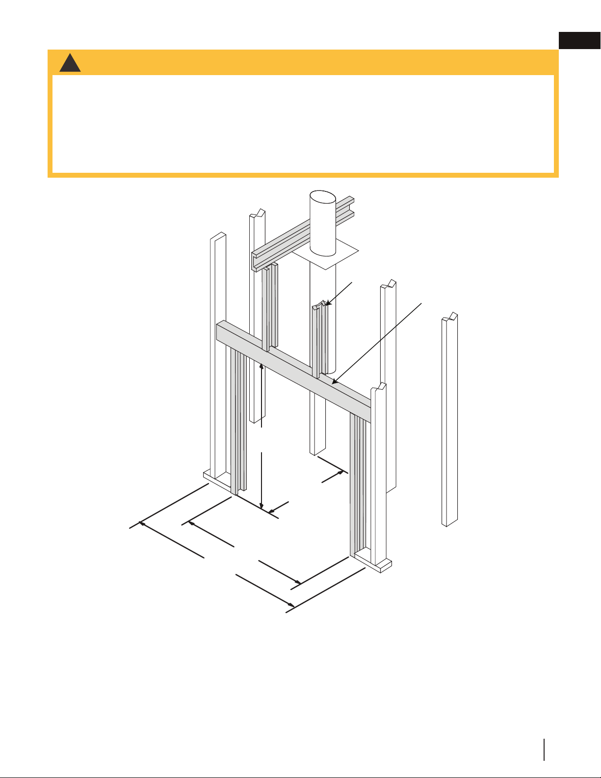
6.0 framing 21
6.1 when using a solid pack chimney 22
6.2 when using an air cooled chimney 22
6.3 minimum clearance to combustibles 23
6.4 minimum enclosure clearances 23
6.5 minimum mantel clearances 24
7.0 finishing 25
7.1 faceplate 25
7.2 upper grill installation 25
7.3 keystone installation 25
7.4 door handle installation 26
7.5 door installation 26
7.6 door latch installation 27
7.7 secondary air tube removal /
installation 27
7.8 fi rebrick and baffl e installation 28
7.9 optional NZ64 blower installation 29
7.10 NZ150-KT kit 31
7.11 NSK6 optional screen kit 31
7.12 smoke shelf 32
8.0 selecting wood 33
9.0 operation 34
9.1 operating sounds and smells 34
9.2 fi re extinguishers, smoke detectors
and carbon monoxide detectors 34
9.3 establishing draft 35
9.4 fuel loading and burn cycle 36
9.5 starting the fi re 37
9.6 smoking 39
10.0 maintenance 40
10.1 ash removal procedures 40
10.2 creosote formation and removal 40
10.3 run-away or chimney fi re 41
10.4 chimney cleaning 41
10.5 glass and gasket replacement 42
10.6 care of glass 42
10.7 NZ64 blower replacement 43
11.0 replacement parts 44
11.1 overview 45
12.0 accessories 46
13.0 troubleshooting 47
14.0 warranty 48
15.0 service history 49
4
note:
Changes, other than editorial, are denoted by a vertical line in the margin.
W415-1501 / E / 12.17.18
Page 5
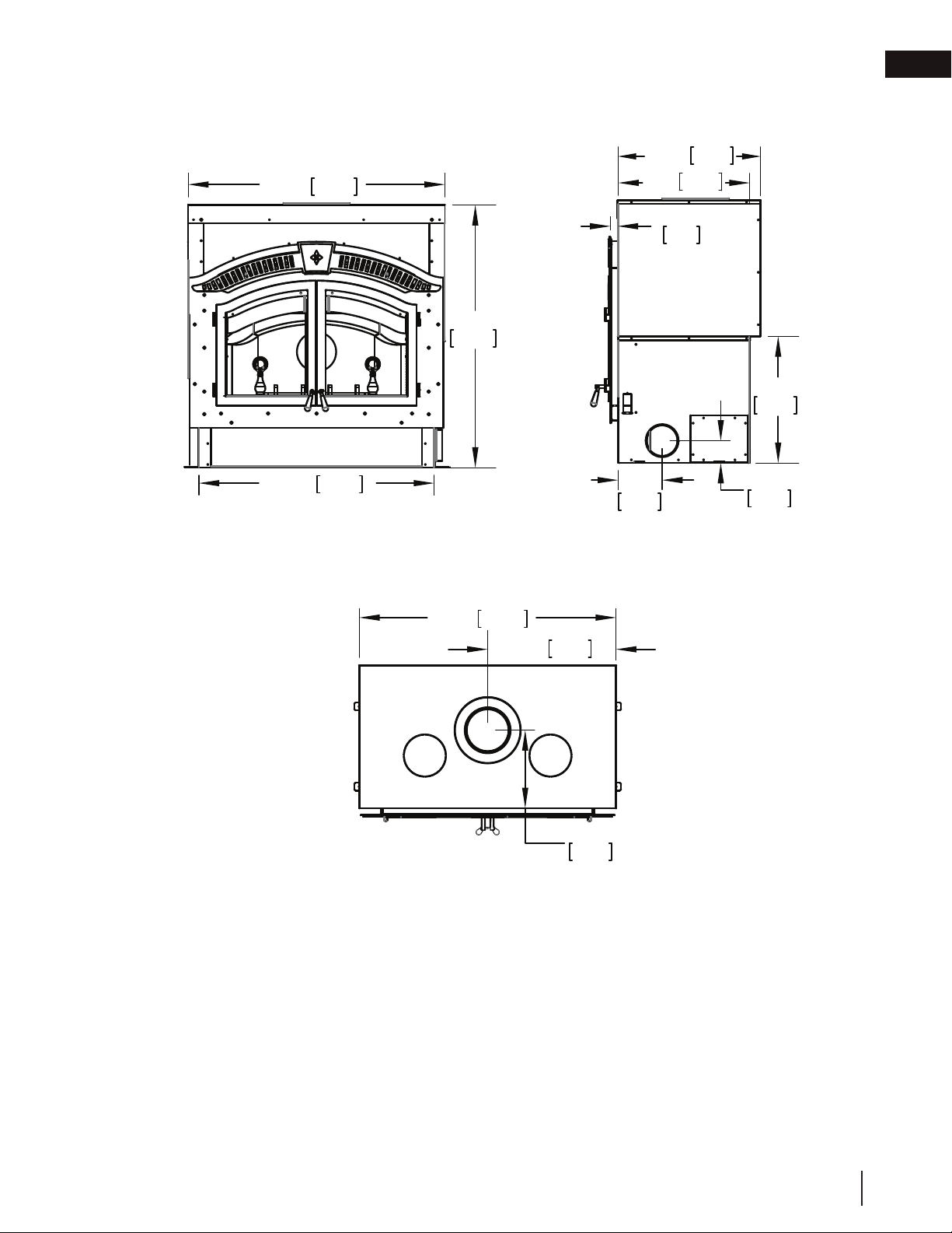
1.0 dimensions
44 15/16"
1141mm
49 1/16"
1246mm
50 1/8"
1273mm
24 3/16"
614mm
8 7/16"
214mm
4 1/4"
108mm
27 3/16"
690mm
25 1/8"
638mm
1 3/8"
36mm
49 1/16"
1246mm
14 7/8"
378mm
24 1/2"
623mm
front view right side view
EN
top view
W415-1501 / E / 12.17.18
5
Page 6
EN
2.0 general information
There are many other appliances in the home competing with this appliance for air, such as kitchen range hoods,
forced air heating devices, and bathroom exhaust fans. Therefore, in order to avoid fi re hazards and/or injuries, be
sure to provide suffi cient combustion air to this appliance.
2.1 general instructions
note:
Do not install an appliance insert or other products/accessories not specifi ed for use with this appliance.
!
WARNING
• Before installing this appliance, contact the local building or fi re authority and follow their guidelines.
• This appliance must be installed by a qualifi ed installer. Follow the installation directions. Do not operate
without fully assembling all components.
• If this appliance is not properly installed, a house fi re may result.
• Do not expose the appliance to the elements (ex. rain, etc.) and keep the appliance dry at all times. Wet
insulation will produce an odour when the appliance is used.
• This appliance is hot when operated and can cause severe burns if contacted. Children and pets must be
kept from touching the appliance when it is hot. Contact your local authorized dealer/distributor for safety
screens that may be available for this product.
• Combustible material such as fi rewood, wet clothing, etc. placed too close can catch fi re. Objects placed
in front of the appliance must be kept a minimum of 48" (121.9cm) from the front of the appliance.
• All wiring should be done by a qualifi ed electrician and shall be in compliance with local codes and with
the national electric code ANSI/NF No. 70-current (in the United States), or with the current CSA C22.1
Canadian Electric Code (in Canada).
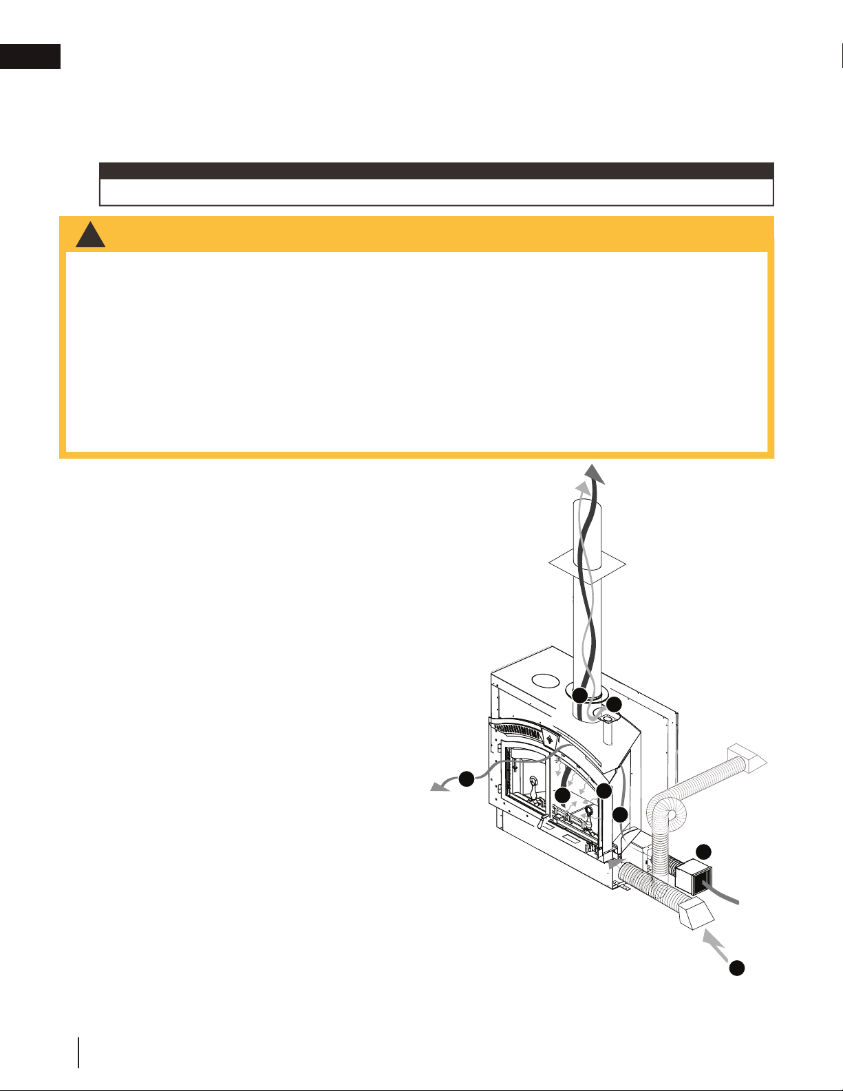
1. Combustion and dilution air is brought into
the appliance through the fresh air intake collars located on the bottom front sides of the
appliance.
2. The combustion air is brought into the fi rebox
through many small holes in the airwash
located at the top and sides of the opening.
3. The dilution air is introduced high in the fi re-
box above the baffl e to cool the chimney.
4. Inside the fi rebox combustion takes place
and exhausts out the chimney.
5. The optional blower can be installed to draw
fresh outside air into the home (not recommended in colder climates), then either the
NZ150-KT kit or the NZ64 blower can be
installed inside and will circulate the air into
your home.
4
3
5
4
2
5
5
6
1
W415-1501 / E / 12.17.18
Page 7

2.2 features
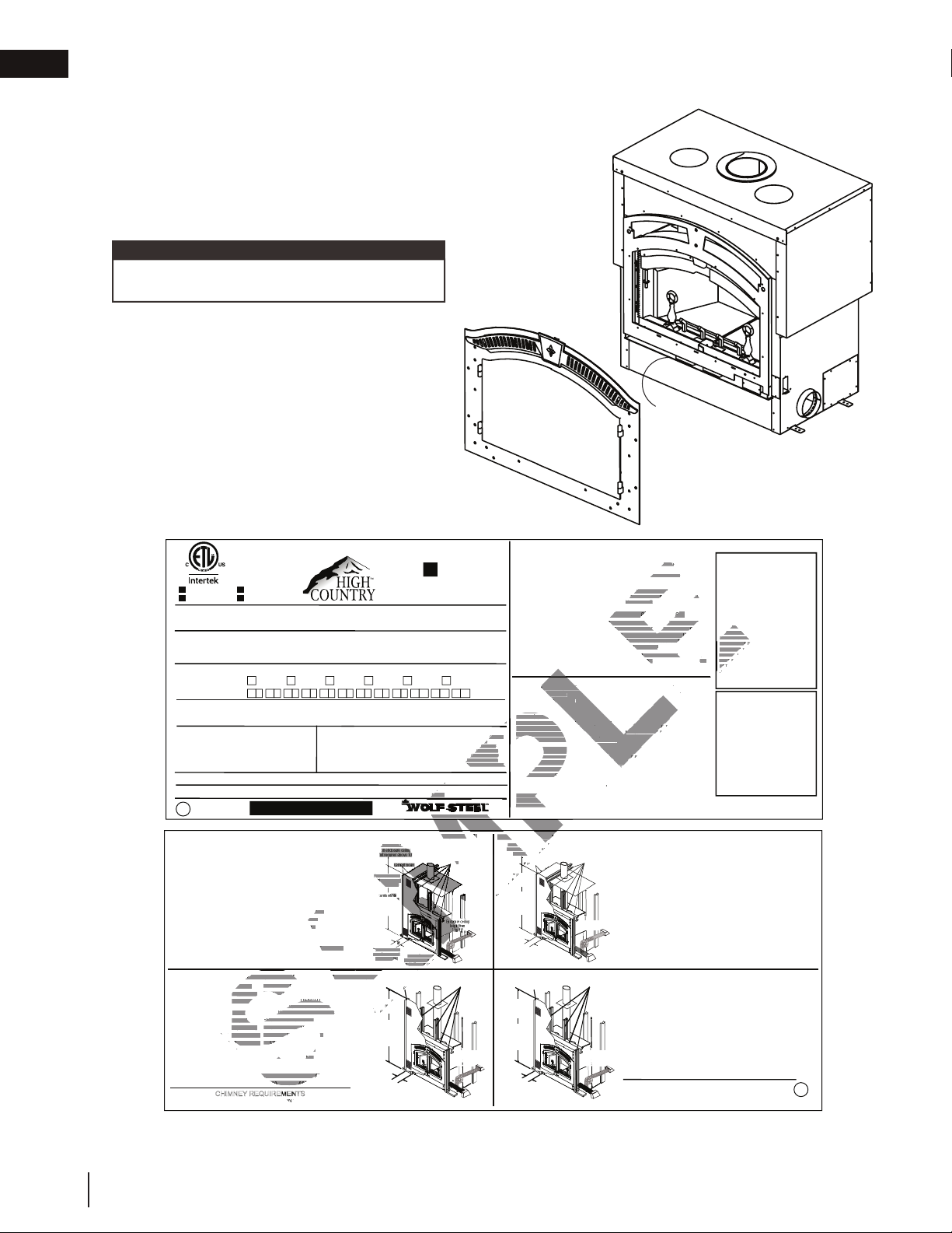
• Maximum log length of 32" (81.3cm)
• Optional 320 CFM blower for convection heat
• Thermostat for automatic control of the blower
• Flue outlet diameter 8" (203.2mm)
2.3 this cordwood fuel appliance
!
WARNING
• Do not let the appliance become hot enough for any part to glow red.
This appliance is a decorative product and not intended as a primary heat source.
Approximate heating capacity up to 1,000 square feet (92 square meters).
2.4 electrical specifi cations
The blower on "HIGH" draws 2.2 amps on 120 volts A.C. (approximately 250 watts).
2.5 packing list
Shipped with appliance: Shipped with faceplate:
Installation manual Faceplate
Baffl e 12 faceplate screws
Ember Strip
Log Retainer Shipped with the door(s):
Flex duct w/ start collar 10' (3m) length, 6" (152mm) Installation instructions and hardware
diameter (1 for NZ150-KT or blower kit and 2 for
outside combustion air supplies).
general information
• Max fuel load 40lbs (18kg)
• Large doors for maximum visibility
• Firebrick lining for fi rebox protection
• Outside air for combustion
EN
W415-1501 / E / 12.17.18
7
Page 8
EN
THE MANUFACTURER'S TURER'S
E
LATE
UNIT
OF UNIT
NIT
T
ace and enclosureFace and enclosure
aFace must have a
tinimum 8' height
board ement board
tthe side of the unit
bustiblesto combustibles
od
t
e
NUFACTUR
ATION INSTRUCTION
OP EDGE OF FACEPLATE
L
)
T
M BASE OF UNIT
NE RETIREZ PAS NE RETIREZ PAS
(see installation manual):(see installation manual):
EHARDWARE
Stainless steel liner must be certified to ULC S640 el liner must be certified to U
SARE-BRA
SPARE-BÛCHES
CCO
)L'APPROVISIONNEMENT EN AIR EXTÉRIEUR)
:FAÇADE :
E
EUR LA FAÇAD
A
ø8"ø
ANGLE DE DÉVIATION MAXIMAL ANGLE DE DÉV
feu.eu.
s une maison mobile.une maison mobile.
struées.
general information
2.6 rating plate information
Rating plate is located behind the appliance faceplate.
This illustration is for reference only. Refer to the rating plate on the appliance for accurate information.
note:
The rating plate must remain with the appliance at all times. It must not be removed.
CERTIFIED TO / CERTIFIÉ SELON: ULC S610, UL-127
MODEL/ NO° DE MODÈLE
NZ6000-1
9700539 (WSL)
4001657 (NGZ)
INSTALL AND USE ONLY IN ACCORDANCE WITH THE MANUFACTURER'S INSTALLATION AND OWNER'S
MANUAL. CONTACT LOCAL BUILDING OR FIRE OFFICIALS ABOUT RESTRICTIONS AND INSTALLATION
INSPECTION IN YOUR AREA. DO NOT CONNECT THIS UNIT TO A CHIMNEY SERVING ANOTHER APPLIANCE.
POUR INSTALLATION ET UTILISATION CONFORMÉMENT AUX MANUEL D'INSTRUCTIONS DU FABRICANT.
RENSEIGNEZ-VOUS AUPRÈS DES AUTORITÉS LOCALES DU BÂTIMENT OU DU SERVICE DES INCENDIES AU
SUJET DES RESTRICTIONS ET DES INSPECTIONS D'INSTALLATION DANS VOTRE RÉGION. NE PAS
RACCORDER À LA CHEMINÉE D'UN AUTRE APPAREIL.
BLOWER KIT / SOUFFLERIE : NZ64
HOT AIR GRAVITY VENTS / VENTILATION PAR GRAVITE: NZ221
WARNING: THIS APPLIANCE HAS NOT BEEN TESTED WITH
AN UNVENTED GAS LOG SET. TO REDUCE RISK OF FIRE OR
INJURY, DO NOT INSTALL AN UNVENTED GAS LOG SET
INTO APPLIANCE.
AVERTISSEMENT: CET APPAREIL N’A PAS ÉTÉ TESTÉ AVEC
LES BÛCHES À GAZ. POUR RÉDUIRE LES RISQUES
D’INCENDIE OU DE BLESSURES, NE PAS INSTALLER UN
BÛCHES À GAZ DANS L’APPAREIL.
INSULATED CHIMNEY MINIMUM CLEARANCES TO
BACK
HEADER
CHIMNEY
MANTEL
TOP FACING
SIDE FACING
ADJACENT SIDEWALL
HEARTH PROTECTION
HEARTH PROTECTION
*TOP OF UNIT
(ENCLOSURE CEILING)
*FOR FURTHER INFORMATION SEE THE MANUFACTURER'S
INSTALLATION AND OPERATING MANUAL.
BACK
HEADER
CHIMNEY
MANTEL
TOP FACING
SIDE FACING
ADJACENT SIDEWALL
HEARTH PROTECTION
HEARTH PROTECTION
*TOP OF UNIT
(ENCLOSURE CEILING)
*FOR FURTHER INFORMATION SEE THE MANUFACTURER'S
INSTALLATION AND OPERATING MANUAL.
STARTER COLLAR NZAC-KT MUST BE USED IN CONJUNCTION WITH
4001658 (NAC)
4001659 (WUSA)
YEAR:
MONTH:
Do not use a fireplace insert or other products not specified for use with this product.
N’utiliser pas un insert de cheminée ou d’autres produits non spécifiées pour l’utilisation avec ce produit.
Replace only with ceramic glass obtained from the dealer and certified for use with this fireplace.
Remplacez uniquement avec du verre obtenu du détaillant et certifié pour l’utilisation avec cet appareil.
SERIAL NO.
COMBUSTIBLES:
0"(0 mm)
96"(2.44 m)
2"(51 mm)
12"(305 mm)
96"(2.44 m)
6"(153 mm)
21"(534 mm)
21"(534 mm)
8"(203 mm)
120"(3.05 m)
AIR COOLED CHIMNEY MINIMUM CLEARANCES TO COMBUSTIBLES:
0"(0 mm)
72"(2.83 m)
2"(51 mm)
12"(305 mm)
84"(3.31 m)
6"(153 mm)
21"(534 mm)
21"(534 mm)
8"(203 mm)
84"(3.31 m)
CHIMNEY REQUIREMENTS
FMI 8DM AIR COOLED CHIMNEY
MANUFACTURE DATE:
2015 2016
243658710912111
OPTIONAL COMPONENTS / PIECES OPTIONNELS
2017 2018
ACCESSORIES PROVIDED BY MANUFACTURER ARE TO BE UTILIZED ONLY/
SEULS LES ACCESSOIRES FOURNIS PAR LE FABRICANT PEUVENT ÊTRE UTILISÉS.
• Operate with feed doors
closed. Open to feed fire only.
• Transport ashes in an air-tight non-combustible
• For use with cord wood only.
• Not for use in a Mobile Home.
• Combustion air openings are not to be obstructed.
NZ6000-1
TO STAND-OFFS
FROM BASE OF UNIT
REFER TO MANUFACTURER'S
INSTALLATION INSTRUCTIONS.
TO TOP EDGE OF FACEPLATE
FROM BASE OF UNIT
FROM SIDE OF UNIT
TO EDGE OF FACEPLATE
FROM FRONT OF UNIT
FROM SIDES OF UNIT
FROM BASE OF UNIT
TO STAND-OFFS
FROM BASE OF UNIT
REFER TO MANUFACTURER'S
INSTALLATION INSTRUCTIONS.
TO TOP EDGE OF FACEPLATE
FROM BASE OF UNIT
FROM SIDE OF UNIT
TO EDGE OF FACEPLATE
FROM FRONT OF UNIT
FROM SIDES OF UNIT
FROM BASE OF UNIT
LISTED FACTORY BUILT FIREPLACE /
FOYER PRÉFABRIQUÉ HOMOLOGUÉ
WARNING:
container.
24 NAPOLEON ROAD. BARRIE, ONTARIO L4M 0G8 CANADA
DO NOT REMOVE THIS LABEL
Cement board and steel studs
Face must have a
must have
minimum 8' height
inimum 8' heigh
of cement board
f cement
facing and wood
acing and wood
framing may start
raming may star
at 96" above the
at 96" above th
base of the unit
of the unit
Cement board from
ement board from
the side of the unit
the side of the uni
Face and enclosure
F
to combustibles
to com
ceiling metal studs, both
clad with cement board
Cement board
Face must have a
minimum 7' height
of cement board
combustible
facing and wood
framing may start
at 84" above the
base of the unit
6"
Cement board from
the side of the unit
to combustibles
clad with cement board
2019 2020
• Tenir les portes fermées lorsque le foyer fonctionne.
incombustible possédant un couvercle étanche.
• Pour emploi avec du boid de corde seulement.
• Ne peut être installé dans une maison mobile.
• Les ouvertures d’air de combustion de doivent pas être
Face metal studs,
AVERTISSEMENT:
N’ouvrez que pour ravitailler le feu.
• Transporter les cendrew dans un contenant
obstruées.
Metal Studs
Metal Studs
Minimum
enclosure ceiling
height 7'
FACEPLATE
RATING
PLATE
LOCATION
COMPONENTS REQUIRED FOR INSTALLATION:
SHIPPED WITH THE FIREPLACE:
INSTALLATION MANUAL
BAFFLE
EMBER STRIP
LOG RETAINER
FLEX DUCT W/ START COLLAR 10' LENGTH,
6" DIA (FOR BLOWER AND OUTSIDE AIR
SUPPLY).
CHIMNEY REQUIREMENTS (see installation manual):
Chimney must be certified to one of the following standards ULC S604, ULC S610
or ULC S629 for Canada or UL 103HT or UL-127 for the United States
Masonry chimney installation: Stainless steel liner must be certified to ULC S640
M92 or ULC 639 for Canada or UL 1777 for the United States
MINIMUM CHIMNEY HEIGHT 15 ft (4.57 m) MAXIMUM NUMBER OF ELBOWS 4
MAXIMUM CHIMNEY HEIGHT 34 ft (10.36 m) FLUE COLLAR 8"ø
MAXIMUM OFFSET ANGLE 30º US - 45º CANADA
COMPOSANTS REQUIS POUR L'INSTALLATION:
LIVRÉ AVEC LE FOYER
MANUEL D'INSTRUCTIONS
DÉFLECTEUR
PARE-BRAISES
PARE-BRAISE
PARE-BÛCHES
PARE-BÛCHE
GAINE FLEXIBLE AVEC COLLET DE RACCORD
DE PRISE D'AIR DE 10', 6" DE DIAMÈTRE
DE PRISE D'AIR DE 10', 6" DE DIAMÈTRE
(POUR LA SOUFFLERIE ET
POUR LA SOUFFLERIE ET
L'APPROVISIONNEMENT EN AIR EXTÉRIEUR)
L'APPROVISIONNEMENT EN AIR EXTÉRIEUR
EXIGENCES POUR LA CHEMINÉE (voir le manuel d'instructions)
La cheminée doit être certifiée selon l'une des normes suivantes : ULC S610 ou ULC S629
Installation dans une cheminée en maçonnerie : La gaine en acier inoxydable doit être
certifiée selon les normes ULC S640 M92 ou ULC 639 pour le Canada ou selon la norme
HAUTEUR MINIMALE DE LA CHEMINÉE 15 pi (4.57 m) NOMBRE MAXIMAL DE COUDES 4
HAUTEUR MAXIMALE DE LA CHEMINÉE 34 pi (10.36 m) BUSE D'ÉVACUATION 8"ø
ANGLE DE DÉVIATION MAXIMAL 30º US - 45º CANADA
NE RETIREZ PAS CETTE PLAQUE
Panneau de ciment et montants
d'acier sur le plafond de l'enclave
non requis à plus de 10'
La façade doit posséder un
panneau de ciment d'une
hauteur minimale de 8'
La façade combustible et la
charpente de bois peuvent
débuter à 96" au-dessus
de la base de l'appareil
Panneau de ciment
sur le côté de
l'appareil aux matériaux
combustibles
DÉGAGEMENTS MINIMAUX DE LA CHEMINÉE REFROIDIE À L'AIR AUX MATÉRIAUX COMBUSTIBLES
La façade doit posséder
un panneau de ciment
d'une hauteur
minimale de 7'
La façade combustible
et la charpente de bois
peuvent débuter à 84"
au-dessus de la base
de l'appareil
Panneau de ciment
sur le côté de
l'appareil aux matériaux
combustibles
Air cooled chimney: Use only FMI 8DM
AINE FLEXIBLE AVEC COLLET DE RA
pour le Canada ou selon les normes UL 103HT ou UL-127 pour les États-Unis
UL 1777 pour les États-Unis
Cheminée refroidie à l'air : Utilisez seulement FMI 8DM
Panneaux de ciment
Panneau de ciment
Montants d'acier
6"
Montants d'acier de façade
et de plafond de l'enclave
recouverts de panneaux de ciment
Montants d'acier
6"
Montants d'acier de façade
recouverts de panneaux de ciment
SHIPPED WITH FACEPLATE:
FACEPLATE
12 FACEPLATE SCREWS
SHIPPED WITH THE DOOR(S):
INSTALLATION INSTRUCTIONS AND
HARDWARE
ARDWAR
LIVRÉ AVEC LA FAÇADE :
LIVRÉ AVEC LA FAÇADE
FAÇADE
AÇAD
12 VIS POUR LA FAÇADE
12 VIS POUR LA FAÇAD
LIVRÉ AVEC LA/LES PORTE(S) :
RD
INSTRUCTIONS D'INSTALLATION
ET QUINCAILLERIE
DÉGAGEMENTS MINIMAUX DE LA CHEMINÉE PRÉFABRIQUÉE
STANDARD AUX MATÉRIAUX COMBUSTIBLES
ARRIÈRE 0"(0 mm) AUX ESPACEURS
LINTEAU 96"(2.44 m) DE LA BASE DE L'APPAREIL
CHEMINÉE 2"(51 mm) RÉFÉREZ-VOUS AU MANUEL
TABLETTE 12"(305 mm) DU HAUT DE LA FAÇADE
DESSUS 96"(2.44 m) DE LA BASE DE L'APPAREIL
CÔTÉ 6"(153 mm) DU CÔTÉ DE L'APPAREIL
MUR LATÉRAL ADJACENT 21"(534 mm) DU BORD DE LA FAÇADE
PROTECTION DE PLANCHER 21"(534 mm) DU DEVANT DU FOYER
PROTECTION DE PLANCHER 8"(203 mm) DES CÔTÉS DU FOYER
*HAUT DE L'APPAREIL 120"(3.05 m) DE LA BASE DE L'APPAREIL
(PLAFOND DE L'ENCLAVE)
*POUR PLUS D'INFORMATIONS, CONSULTEZ LE MANUEL
Hauteur minimale
du plafond de
l'enclave de 7' à 10'
Hauteur minimale
du plafond de
l'enclave de 7'
D'INSTRUCTIONS DU FABRICANT.
ARRIÈRE 0"(0 mm) AUX ESPACEURS
LINTEAU 72"(2.83 m) DE LA BASE DE L'APPAREIL
CHEMINÉE 2"(51 mm) RÉFÉREZ-VOUS AU MANUEL
TABLETTE 12"(305 mm) DU HAUT DE LA FAÇADE
DESSUS 84"(3.31 m) DE LA BASE DE L'APPAREIL
CÔTÉ 6"(153 mm) DU CÔTÉ DE L'APPAREIL
MUR LATÉRAL ADJACENT 21"(534 mm) DU BORD DE LA FAÇADE
PROTECTION DE PLANCHER 21"(534 mm) DU DEVANT DU FOYER
PROTECTION DE PLANCHER 8"(203 mm) DES CÔTÉS DU FOYER
*HAUT DE L'APPAREIL 84"(3.31 m) DE LA BASE DE L'APPAREIL
(PLAFOND DE L'ENCLAVE)
*POUR PLUS D'INFORMATIONS, CONSULTEZ LE
MANUEL D'INSTRUCTIONS DU FABRICANT.
SPÉCIFICATIONS POUR LA CHEMINÉE
LE COLLET DE DÉPART NZAC-KT DOIT ÊTRE UTILISÉ
CONJOINTEMENT AVEC LA CHEMINÉE REFROIDIE À L'AIR FMI 8DM
PREVENT CREOSOTE FIRE: INSPECT
CHIMNEY AND CHIMNEY CONNECTOR, IF
APPLICABLE, TWICE MONTHLY AND CLEAN
IF NECESSARY.
DO NOT OVERFIRE: IF EXTERIOR OF UNIT
GLOWS RED, YOU ARE OVERFIRING.
KEEP FURNISHINGS AND OTHER
COMBUSTIBLE MATERIALS A
CONSIDERABLE DISTANCE AWAY FROM
APPLIANCE.
TYPE OF FUEL: WOOD ONLY.
PREVENIR LES FEUX DE CREOSOTE:
INSPECTEZ LA CHEMINEE OU LE RACCORD
DE CHEMINEE, SI APPLICABLE, DEUX FOIS
PAR MOIS ET NETTOYEZ SI NECESSAIRE.
NE SURCHAUFFEZ PAS: SI L'EXTERIEUR DE
L'UNITE DEVIENT ROUGE, VOUS
SURCHAUFFEZ.
GARDEZ LES MEUBLES ET AUTRES
"
MATERIELS COMBUSTIBLES A UNE
DISTANCE CONSIDERABLE DE L'APPAREIL
DE CHAUFFAGE.
TYPE DE COMBUSTIBLE: BOIS SEULEMENT.
BEFORE COMMENCING INSTALLATION
REFER TO THE LABEL LOCATED BEHIND
THE FACEPLATE AND TO THE
MANUFACTURER'S INSTALLATION
INSTRUCTIONS PACKAGED TOGETHER
WITH THIS UNIT.
THE INSTALLATION MUST BE APPROVED
BY THE AUTHORITY HAVING
JURISDICTION.
AVANT DE COMMENCER L'INSTALLATION,
REFEREZ-VOUS À L'ÉTIQUETTE QUI SE
TROUVE DERRIÈRE LA FAÇADE AINSI
QU'AUX INSTRUCTIONS D'INSTALLATION
DU MANUFACTURIER FOURNIES AVEC
L'UNITÉ.
L'INSTALLATION DOIT ÊTRE APPROUVÉE
PAR L'AUTORITÉ COMPÉTENTE.
D'INSTRUCTIONS DU FABRICANT.
D'INSTRUCTIONS DU FABRICANT.
IMPORTANT
W385-2065 / D
W385-2065 / D
8
W415-1501 / E / 12.17.18
Page 9
3.0 installation overview
!
WARNING
• This appliance and its components are designed to be installed and operated as a system. Any alteration
to or substitution for items in this system, unless allowed by these installation instructions, will void the ETL
listing and may void the product warranty. It may also create a hazardous installation. Read through these
instructions thoroughly before starting your installation and follow them carefully throughout your project.
SEE
SEE
VENTILATION
SEE
MINIMUM
MANTEL
CLEARANCES
GLASS AND
GASKET
REPLACEMENT
CARE OF GLASS
OPENINGS
SEE
&
CHIMNEY
INSTALLATION
SEE
FRAMING
SEE
CONNECTION
TO A MASONRY
CHIMNEY
SEE
OUTSIDE
COMBUSTION
AIR
SEE
HIGH
EFFICIENCY
HEATING
EN
SEE
RATING PLATE
INFORMTATION
SEE
FIREBRICK
INSTALLATION
SEE
HEARTH
EXTENSION
SEE
DOOR HANDLE
INSTALLATION
SEE OPTIONAL
NZ64
BLOWER
INSTALLATION
SEE
OUTSIDE
COMBUSTION
AIR
W415-1501 / E / 12.17.18
9
Page 10
EN
4.0 installation planning
WARNING
!
• Wear gloves, protective footwear and safety glasses for protection.
• Carefully follow the instructions for assembly of the pipe and other parts needed to install the appliance.
Failure to do so may result in a fi re, especially if combustibles are too close to the appliance or chimney and air
spacers are blocked, preventing the free movement of cooling air.
• Do not draw outside air from garage spaces. Exhaust products of gasoline engines are hazardous. Do not
install outside air ducts such that the air may be drawn from attic spaces, basements or above the roofi ng
where other heating appliances or fans and chimneys exhaust or utilize air. These precautions will reduce the
possibility of appliance smoking or air fl ow reversal. The outside air inlet must remain clear of leaves, debris, ice
and/or snow. It must be unrestricted while appliance is in use to prevent room air starvation which can cause
smoke spillage and an inability to maintain a fi re. Smoke spillage can also set off smoke alarms.
• Negative pressure within your home may inadvertently affect your appliance.
• To prevent contact with sagging or loose insulation, the appliance must not be installed against vapour barriers
or exposed insulation. Localized overheating could occur and a fi re could result.
• Do not use makeshift compromises during installation. Do not block or restrict air, grille or louvre openings. Do
not add a hood.
• To prevent personal injury, keep hand tools in good condition, sharpen cutting edges and make sure tool
handles are secure.
• Always maintain the minimum air space required in the enclosure to prevent fi res.
• Check with local building offi cials for any permits required for installation of this appliance and notify your
insurance company prior to proceeding.
!
WARNING
• Do not install into any area having a height less than 7 feet (2.1m) (ceiling of enclosure to appliance
bottom, excluding hearth height).
The appliance is shipped with a set-up face that is 1/8" (3.2mm) larger on the top,
bottom and each side than the faceplate. Leave the set-up face in place to act as a
template when installing the fi nishing face.
important:
This appliance, fully dressed, weighs 850lbs (386kg). Ensure there is
adequate fl oor support for the appliance, chimney, and facing material.
Some material could weigh thousands of pounds.
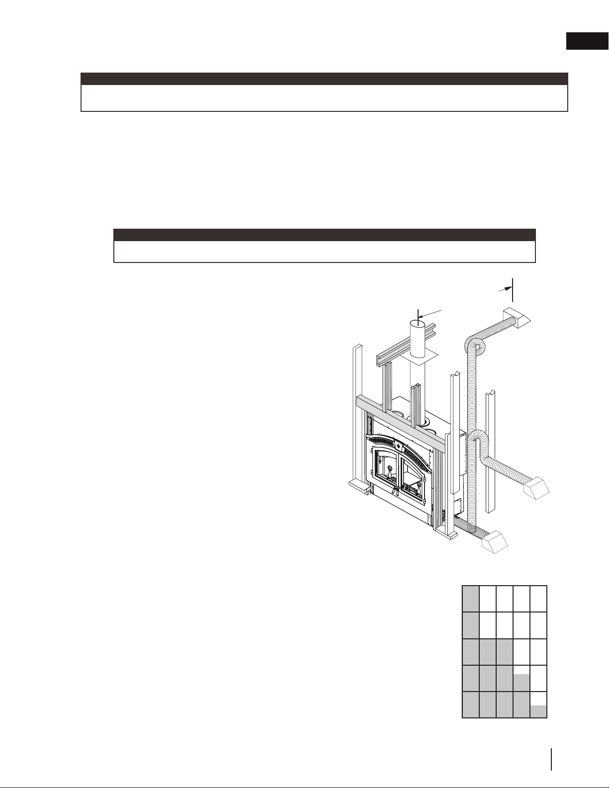
4.1 location and clearances
We recommend that the appliance be secured to the fl oor in
all cases.
Using the door opening as a datum, level the appliance by
shimming underneath the appliance. Remove and discard the
lifting handles. Bend the tabs down and secure the appliance to
the fl oor.
10
W415-1501 / E / 12.17.18
Page 11
4.2 ventilation openings
note:
In order to avoid fi re hazards and/or injuries, the appliance enclosure must be provided with suffi cient air
circulation.
Install ventilation grilles (minimum openings of 40 sq. inches (0.03 sq. meters)) at both fl oor and ceiling levels of the
enclosure. These grilles must not restrict the fl ow of heat by more than 25%. Do not install into any area having
a height less than 7 ft (2m) (ceiling of enclosure to appliance bottom, excluding hearth height). The location of
windows, doors and the traffi c fl ow in the room where the stove is to be located should be considered. If possible,
you should choose a location where the chimney will pass through the house without cutting a fl oor or roof joist.
For more information on ventillation grilles and openings, see "when using a solid pack chimney" section.
4.3 outside combustion air
note:
Incorporate a vertical loop or trap into air liners to reduce air fl ow when appliance is not in use.
Insulating the intake liners is recommended in colder
climates to prevent condensation from occurring.
The Napoleon Model NZ6000-1 takes outside air
directly into the appliance through the openings in the
left and right hand sides.
installation planning
10' (3m) MIN. TO
CHIMNEY CAP.
EN
Decide on the most convenient location for the fresh air
inlet ducts and hoods which may be installed above or
below fl oor level.
The fresh air inlet ducts and hoods must be installed.
Secure and seal the intake liners to the collars using 3
sheet metal screws, and high temperature sealant.
Vertical rise is between:
6' (1.8m) & 10' (3m) max
3' (0.9m) & 6' (1.8m)
1' (0.3m) & 3' (0.9m)
0' (0m) & 1' (0.3m)
Horizontal run may be:
5' (1.5m)
15' (4.6m)
20' (6.1m)
25' (7.6m)
Included with the appliance are:
- Two 10' (3m) lengths of vent. Use a connector
and seal if adding more length.
- Two of intake hoods.
The vertical height of the air intake liner must not be greater than
2/3 the height of the chimney. If additional liner length is required, it may
be doubled by increasing the size from 6" (152mm) diameter to 8" (203mm)
diameter. Use a 6" (152mm) to 8" (203mm) increaser at the hood and a
decreaser at the appliance. Values in brackets represent 8" (203mm) diameter
intake liners.
The duct terminations must be located so they can not be blocked (i.e.
snowdrifts). 4' (1.2m) above grade is recommended. Make a 6 ½" (165mm)
inch hole to suit in an outside wall of the house. From outside, place the fresh
air hood into the hole, open side down. Seal with caulking and secure.
AIR INTAKE LINERS
10 (20)
8 (16)
6 (12)
4 (8)
VERTICAL RISE
2 (4)
0
5
(10)10(20)15(30)20(40)25(50)
HORIZONTAL RUN
W415-1501 / E / 12.17.18
11
Page 12
EN
installation planning
4.4 fl oor protection
4.4.1 ember strip and hearth extensions
!
WARNING
• Hearth extensions are to be installed only as described to prevent high temperatures from occurring on
concealed combustible materials. Hearth ember strips prevent burning or hot particles from inadvertently falling
directly on combustible surfaces in the event the building should settle and disturb the original construction.
An acceptable 61 ½" (156.2cm) x 20" (50.8cm) non-combustible (ie:
brick, stone or ceramic tile) hearth extension must be installed. Hearth
must extend 20" (50.8cm) in front of the faceplate when it is not elevated
(see local building codes). Hearth must extend a minimum of 6" (152mm) to
both sides of the appliance [61 ½" (156.2cm)].
The hearth must extend a minimum 20" (50.8cm) in front of the appliance
although if raised a minimum of 6 1/2" (165mm), the 20" (50.8cm) may be
reduced to a minimum of 18" (45.7cm).
The hearth must extend a minimum of 6" (152mm) to both sides of the
appliance [61 ½" (156.2cm)]
The hearth must be a minimum of 1" (25mm) thick cement board (or
equivalent) plus ¼" (6.4mm) ceramic tile.
Ensure that the gap between the appliance and a non-combustible
hearth extension is sealed with sand/cement grout or covered with
an ember strip (or both) to prevent sparks and embers from falling
into this area.
Raised hearths must be constructed of non-combustible materials such as cement blocks or bricks.
While the appliance can be installed directly on the fl oor, a non-combustible hearth extension is required in front
of the appliance, that must not be built higher than the bottom of the appliance faceplate. It may therefore be
advisable to build the appliance on a raised platform.
A raised hearth together with the appliance built on a raised platform is recommended for easier wood loading and fi re
viewing.
EMBER STRIP
(See “HEARTH
EXAMPLES” Section)
12
W415-1501 / E / 12.17.18
Page 13
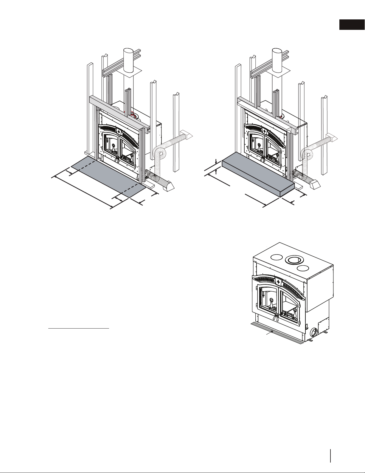
4.4.2 hearth extension
6"
(152mm)
61
1
/2" (1562mm)
(152mm)
6"
20" (508mm)
1
/2"
6
(165mm)
(1562mm)
installation planning
61
1
/2"
18" (457mm)
EN
An acceptable 61 ½" (156.2cm) x 20" (50.8cm) non-combustible (ie: brick,
stone or ceramic tile) hearth extension must be installed. Hearth must
extend 20" (50.8cm) in front of the faceplate when it is not elevated (see
local building codes). Hearth must extend a minimum of 6" (152mm) to
both sides of the appliance [61½" (156.2cm)].
Hearth must be a minimum of 1" (25mm) thick cement board (or
equivalent) plus ¼" (6.4mm) ceramic tile.
Ensure that the gap between the appliance and a combustible hearth
extension is sealed with sand/cement grout or covered with a metal strip
(or both) to prevent sparks and embers from falling into this area.
HEARTH EXTENSION
Elevated hearths must be constructed of noncombustible materials such
as cement blocks or bricks.
While the appliance can be installed directly on the fl oor, a noncombustible hearth extension is required in front of the appliance, that
must not be built higher than the bottom of the appliance faceplate. It may therefore be advisable to build the
appliance on a raised platform.
Hearths raised minimum 6 ½" (165mm) must extend a minimum of 18" (45.7cm).
EMBER STRIP
SEE HEARTH
EXAMPLES
W415-1501 / E / 12.17.18
13
Page 14

EN
installation planning
4.4.3 hearth examples
FLUSH HEARTH
MIN. 1/4” (6.4mm)
TILE OR MARBLE
COMBUSTIBLE FLOOR
RAISED HEARTH
COMBUSTIBLE FLOOR
20” MIN.
(50.8cm)
MIN. 1” (25mm) CEMENT BOARD
18" MIN.
20” MIN.
(45.7cm)
(50.8cm)
6
1
/
”
2
(165mm)
NON-COMBUSTIBLE MATERIALS
SUCH AS CEMENT
BLOCKS OR BRICKS
FACEPLATE
EMBER STRIP
FACEPLATE
EMBER STRIP
RAISED APPLIANCE
MIN. 1/4” (6.4mm)
TILE OR MARBLE
MIN. 1” (25mm)
CEMENT BOARD
PLYWOOD
RAISED HEARTH AND APPLIANCE
MIN. 1/4” (6.4mm)
MARBLE OR STONE
NON-COMBUSTIBLE
MATERIALS SUCH
AS CEMENT BLOCKS
OR BRICKS
PLYWOOD
20” MIN.
(50.8cm)
RAISED
APPLIANCE
COMBUSTIBLE FRAMING
20” MIN.
18" MIN.
(45.7cm)
(50.8cm)
RAISED
APPLIANCE
COMBUSTIBLE FRAMING
FACEPLATE
EMBER STRIP
FACEPLATE
RAISED
HEARTH
EMBER STRIP
WARNING:
Ensure raised
platform is
designed to
support load of
fully loaded
appliance.
INCREASE
HEADER HEIGHT
THIS DIMENSION
See “Framing” section
WARNING:
Ensure raised
platform is
designed to
support load of
fully loaded
appliance.
INCREASE
HEADER HEIGHT
THIS DIMENSION
See “Framing” section
14
W415-1501 / E / 12.17.18
Page 15

5.0 installation
!
WARNING
• Never install a single wall slip section or smoke pipe in a chase structure. The higher temperature of this single
wall pipe may radiate suffi cient heat to combustible chase materials to cause a fi re.
• To avoid danger of fi re, all instructions must be strictly followed, incluidng the provision of air space clearance
between chimney system and enclosure. To protect against the effects of erosion on those parts exposed to
the weather, we recommend that the chase top be painted with a rust-resistant paint.
• Maintain a minimum 2" (51mm) air clearance to all parts of the chimney system at all times. Failure to maintain
this 2" (51mm) air clearance will cause a structure fi re.
• Detailed instructions for installation of the chase top, storm collar, and termination cap are packaged with these
parts.
• Firestop spacers must be used whenever the chimney penetrates a ceiling/fl oor area.
• The chimney must be sound and free of cracks. Clean your chimney a minimum of twice a year, and as
required.
A raised hearth, together with the appliance built on a raised platform, is recommended for easier wood loading
and fi re viewing.
5.1 chimney
note:
All venting connections must be in compliance with the chimney manufacturer’s installation instructions.
This appliance was tested to CAN/ULC S610 and UL 127 Factory Built Fireplace Standards. This appliance has
met the test criteria for Zero Clearance Installation to Combustible Surfaces and Certifi ed to burn fi rewood only.
Any chimney listed to the following standards; CAN/ULC-S604 and CAN/ULC-S629 for Canada or UL-103 or UL103HT for the United States may be installed.
note:
Use only the chimney diameter specifi ed on the rating plate of the
appliance.
EN
Installation of all types of factory-built chimney systems is to be in
accordance with the chimney manufacturers installation instructions.
An appropriate chimney manufacturers anchor base plate and anchor
base plate gasket is required in order to initiate their system. Use
the high temperature gasket, supplied, to seal between the anchor
plate and the appliance top. Air cooled chimney systems are not
recommended in colder climates.
For complete installation instructions, refer to instructions provided with
the manufactured chimney system.
A chimney venting the appliance shall not vent any other appliance. The minimum overall chimney height from
the top of the appliance is 15ft (4.6m). The maximum overall chimney height from the top of the appliance is 34ft
(10.4m).
Factory-built chimney systems for use in dwellings constructed for three or more families must be enclosed
above the room in which the appliance is located. This enclosure must have a fi re resistance rating equal to or
greater than that of the fl oor or roof assembly through which they pass.
The chimney should not be built with an offset angle in excess of 45° in Canada and 30° in USA.
Ensure that minimum clearances are maintained.
Portions of the chimney that extend through accessible spaces must always be encased to avoid personal
contact with the chimney and thereby avoid damage to the chimney.
The chimney must be supported at a maximum of 20ft (6.1m) intervals. Every 20 ft (6.1m) of chimney can weigh
up to approximately 200lbs (90.7kg).
ANCHOR PLATE FOR A FACTORY
ANCHOR PLATE
ANCHOR PLATE GASKET
APPLIANCE TOP
BUILT CHIMNEY
W415-1501 / E / 12.17.18
15
Page 16
EN
installation
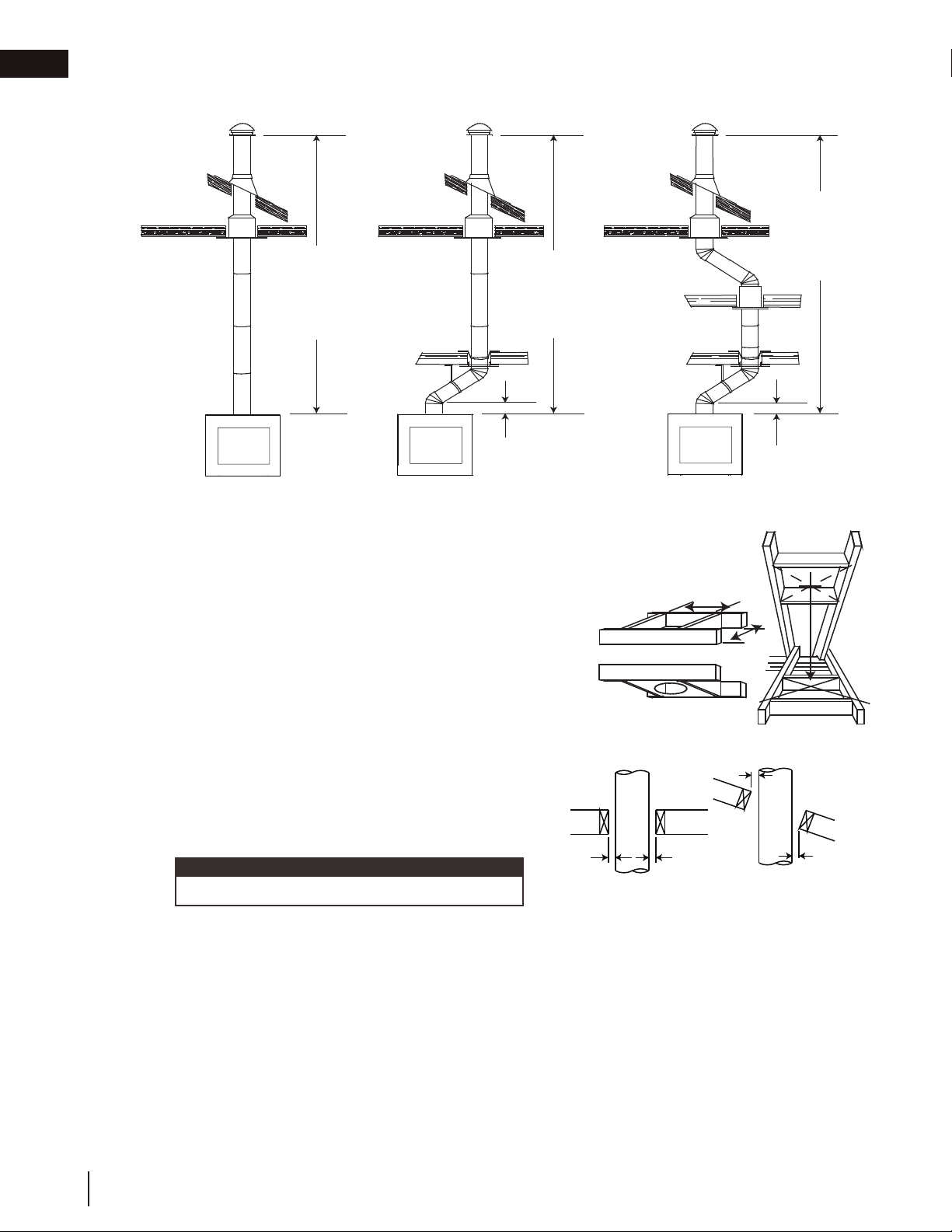
5.2 typical chimney installation
RAIN CAP
RAIN CAP
RAIN CAP
STORM COLLAR
ROOF FLASHING
ATTIC INSULATION
SHIELD
15 FT
(4.6m)
MINIMUM
34 FT
(10.4m)
MAXIMUM
STORM COLLAR
ROOF FLASHING
ATTIC INSULATION
SHIELD
OFFSET
SUPPORT
15 FT
(4.6m)
MINIMUM
34 FT
(10.4m)
MAXIMUM
FIRESTOP
12” (30.5cm)
STORM COLLAR
ROOF FLASHING
ATTIC INSULATION
SHIELD
CEILING RADIATION
SHIELD
OFFSET
SUPPORT
MIN*
STRAIGHT CHIMNEY SINGLE OFF-SET CHIMNEY DOUBLE OFF-SET CHIMNEY
* The first flue offset closest to the top of the appliance must be a
minimum distance of 12” (30.5cm) from the top of the appliance.
A. Move the appliance into position. Try to center the exhaust
flue of the appliance, midpoint between two joists to prevent
having to cut them. Use a plumb bob to line up the centre.
B. Cut and frame an opening in the ceiling to provide a
HEADERS
minimum clearance of 2” (50.8mm) between the outside of
the chimney and any combustible material. DO NOT FILL
THIS SPACE WITH ANY TYPE OF MATERIAL! Nail headers
between the joists for extra support. Firestop spacers must
be placed on each framed opening in any floor or ceiling
that the chimney passes through.
FIRESTOP SPACER UNDERSIDE OF JOIST
2" (50.8mm)
Min.
C. Hold a plumb bob from the underside of the roof to
determine where the opening in the roof should be.
Cut and frame the roof opening maintaining proper
2” (50.8mm) clearances.
note:
30° or 45° offsets may be installed back to back.
2" (50.8mm)
Min.
2" (50.8mm)
Min.
Typical Roof Joist FramingTypical Joist Framing
15 FT
(4.6m)
MINIMUM
34 FT
(10.4m)
MAXIMUM
FIRESTOP
12” (30.5cm)
MIN*
2" (50.8mm)
Min.
16
W415-1501 / E / 12.17.18
Page 17
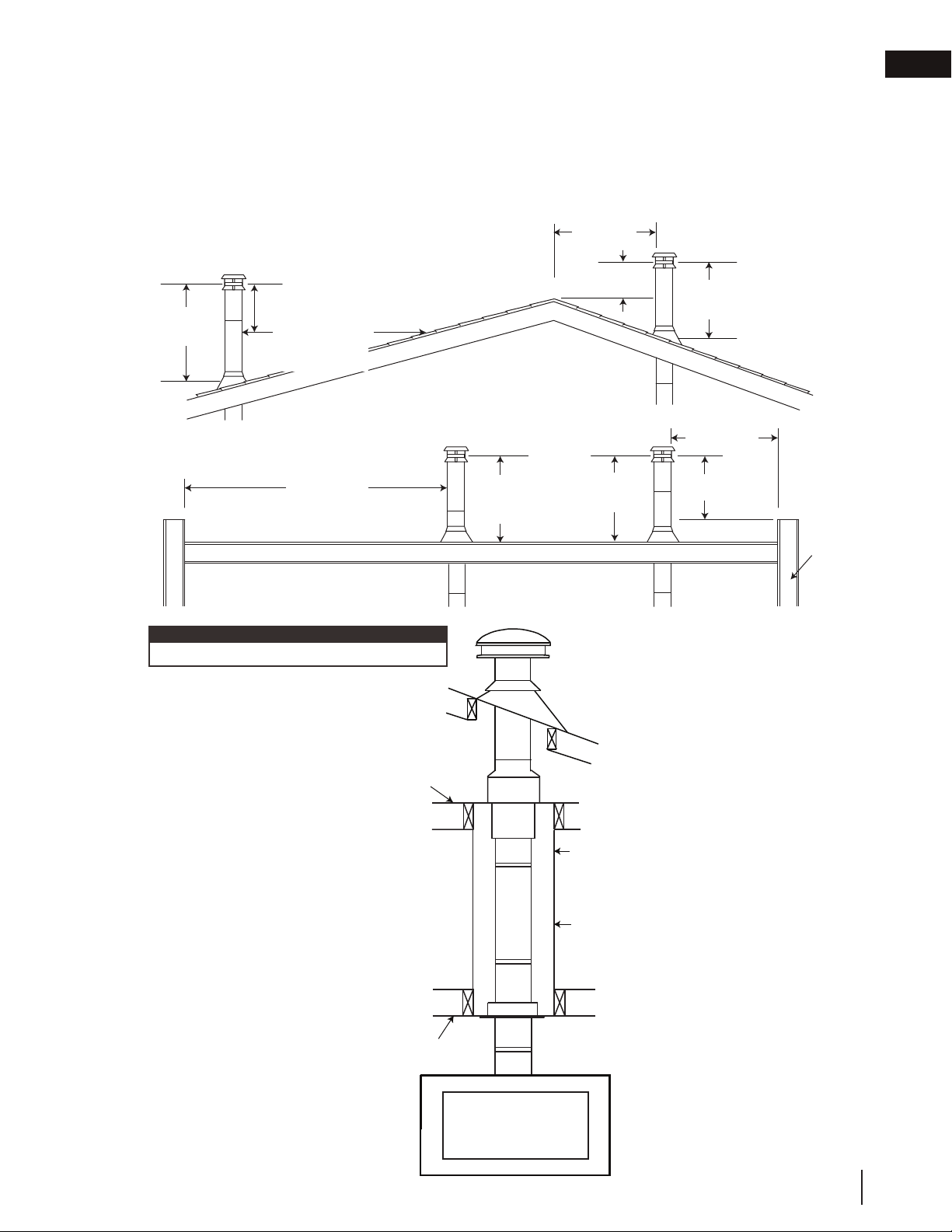
5.3 adding chimney sections
Add chimney sections, according to the manufacturer’s installation instructions. If the chimney system passes
through an attic space, a rafter radiation shield or attic insulation shield is required. The chimney must extend at
least 3ft (0.9m) above its point of contact with the roof and at least 2ft (0.6m) higher than any wall, roof or building
within 10ft (3.1m). If the chimney extends more than 5ft (1.5m) above the roof, it must be secured using a roof
brace or guide wires. A raincap must be installed to avoid internal damage and corrosion.
3 FT (1m)
MIN
2 FT (0.6m) MIN
10 FT (3m)
TO NEAREST
ROOFLINE
RIDGE
LESS THAN
10FT (3m)
2 FT (0.6m)
MIN
installation
3 FT (1m)
MIN
LESS THAN
10FT (3m)
EN
10 FT (3m)
OR MORE
FLAT ROOF
note:
This illustration is for wood appliances only.
Ceiling Joist
LIVING SPACE
Chimney must be
totally enclosed
when passing
through living space
with a minimum 2”
(51mm) clearance
to combustibles.
3 FT (1m)
MIN
3 FT (1m)
MIN
ATTIC SPACE
Chimney Lengths
Framed
Enclosure
2” (51mm)
clearance from
chimney to
combustible wall
2 FT (0.6m)
MIN
WALL
Floor, Ceiling Joist
W415-1501 / E / 12.17.18
17
Page 18
EN
installation
5.4 offset chimney installation
WARNING
!
• Chimney sections installed between an offset and return require structural support to reduce off-center
loading and to prevent chimney sections from separating at the chimney joists.
• The chimney should not be built with an offset angle in excess of 45° in Canada and 30° in USA. Do not
combine offset chimney components to exceed these angles.
The first flue offset closest to the top of the
appliance must be a minimum distance of
12" (30.5cm) from the top of the appliance.
Attach an elbow to the chimney section, angled
toward the offset. Secure according to chimney
manufacturer’s instructions. Chimney sections must
be adequately secured one to the other to ensure
they do not separate. To achieve the minimum
offset, attach and secure a second elbow. To
achieve longer offsets, you may install any available
length of chimney pipe between the elbows.
Supports must be used on the first vertical chimney
section after a return elbow.
Storm Collar
Roof Joist
Chimney Section
Elbow Support
Straps
Elbow
Rain Cap
Roof
Flashing
Attic Insulation
Shield
Elbow Support
Band
Elbow
Floor , Ceiling Joist
Firestop
18
If the offset length is more than 36” (91.4cm), an
intermediate support must be employed. To
achieve longer offsets, you may install any
available length of chimney pipe between the
elbows.The intermediate support must be used
in conjunction with an offset support.
W415-1501 / E / 12.17.18
Page 19
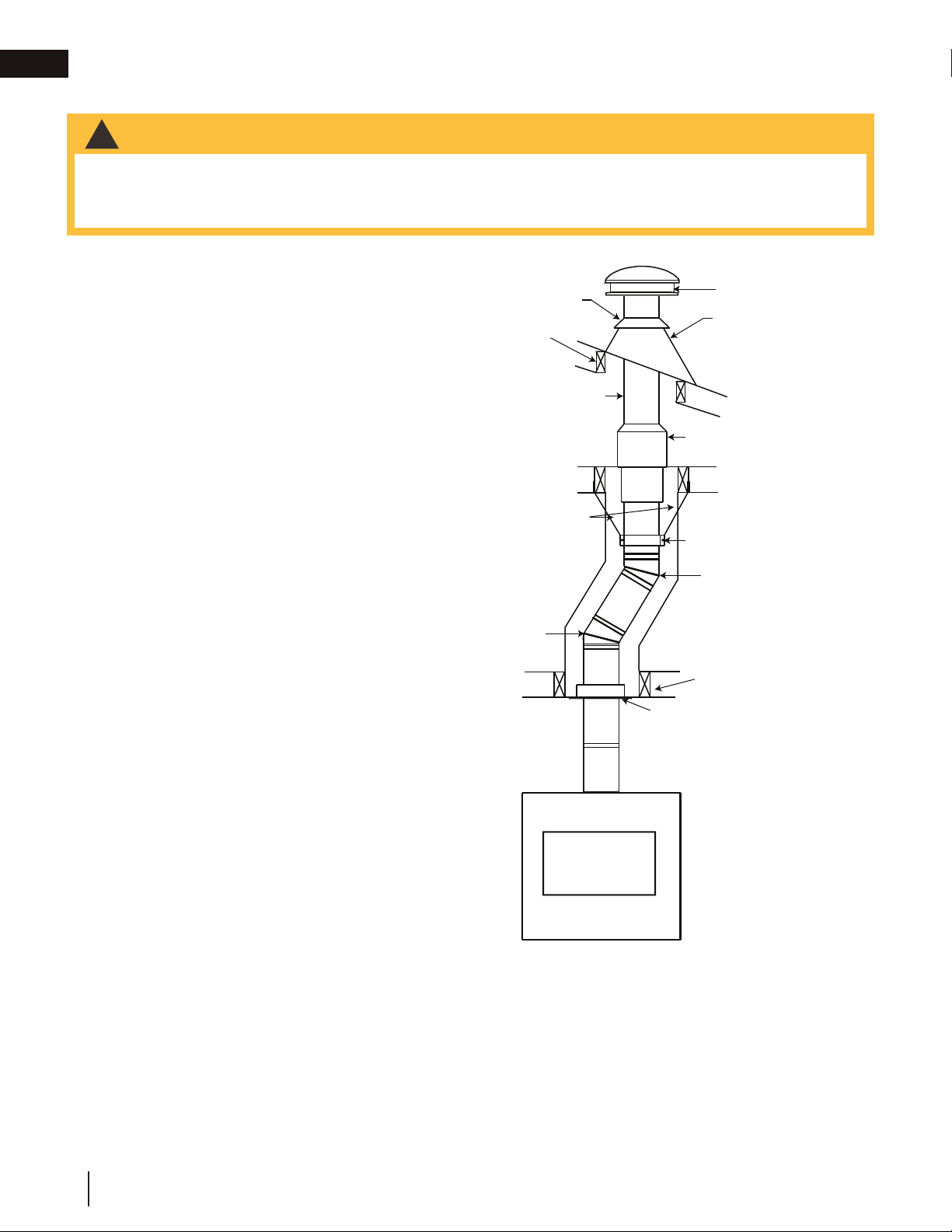
5.5 installing fl ashing and storm collar
The following are generic installation instructions for installing the flashing around a chimney. Installation of all
types of factory-built chimney systems is to be in accordance with the chimney manufacturer’s installation
instructions. Remove the nails from the shingles above and to the sides of the chimney. Place the flashing over
the chimney pipe and slide underneath the sides and upper edge
of the shingles. Ensure that the chimney pipe is properly
centered within the flashing, giving a 3/4” (19.1mm) margin all
around. Fasten to the roof on the top and sides. DO NOT NAIL
through the lower portion of the flashing. Make weather-tight by
sealing with caulking. Where possible, cover the sides and top
edges of the flashing with roofing material. Apply waterproof
caulking, provided with the flashing, around the chimney, 1”
(25.4mm) above the top of the flashing and push the storm collar
down into the caulking. Insert a rain cap onto the top of the last
chimney section.
5.6 connection to a masonry chimney
The appliance may be connected to either a lined or unlined
masonry chimney.
IF THE CHIMNEY IS LINED:
The fl ues must be made of
vitrifi ed clay and be in sizes
of 8” (203.2mm) square or
8” (203.2mm) round (inside
diameters) or 8”x12” [(203.2mm
x 304.8mm)] with a minimum
height of 15 feet (4.6m) above
the appliance.
HI-TEMP GASKET
ANGLE IRON TO SUPPORT
CHIMNEY WEIGHT
ON BRICK SIDE-WALLS,
FLUE TILE
FLUE TILE
SUPPORT
APPLIANCE TOP
ANGLE IRON RESTS
FREE OF UNIT.
installation
RAIN CAP
CAULKING
STORM COLLAR
WEATHER
SEALANT
FLASHING
LINER
SUPPORT
USE AN 7” (177.8mm)
OR 8" (203.2mm) LINER
WITH A DRIPLESS TYPE
A CONNECTOR
(IF USING 7” (177.8mm)
A 7” TO 8” INCREASER
FROM LINER TO FLUE
ALSO CAN BE USED.)
EN
8” (203.2mm) round fl ues are
recommended.
LINED CHIMNEY INSTALL
UNLINED CHIMNEY INSTALL
Installation must conform to both national and local code requirements.
IF THE CHIMNEY IS UNLINED:
A stainless steel liner listed to either Standard ULC-S640M in
Canada or UL-1777 in the USA, must be used. Liners for new
masonry chimneys may be used to connect the appliance to the
chimney. The liner must be continuous from the appliance to the
chimney cap and be installed only per manufacturers instructions.
In both cases, the chimney structure must be supported by angle
iron anchored into the masonry walls. The allowable masonry used
in chimney construction is 3 1/2” (88.9mm) brick, solidly mortared
and must fully encase the fl ue. Ensure there are no leaks.
FOR A MASONRY APPLIANCE USE A
PRE-FABRICATED CHIMNEY USE AN
HI-TEMP GASKET
APPLIANCE TOP
FLUE TILE SUPPORT. FOR A
ANCHOR PLATE.
In no case is the masonry enclosure to be supported by the appliance. Allow a 1” (25.4mm) air cavity for expansion. Use the fl ue tile support accessory, see your local authorized dealer / distributor.
note:
The fl ue tile support is to be suspended on appropriate lintels.
W415-1501 / E / 12.17.18
19
Page 20
EN
installation
5.7 air cooled chimney installation
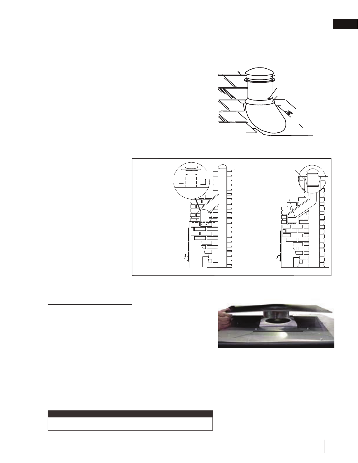
A. Remove the knock out.
B. Cut away the insulation to gain access to the ring.
C. Remove the ring secured by four screws.
D. Slide the starter collar through the insulation wrap and
affi x using the four screws removed in step C.
E. Secure the inner liner of the chimney to the appliance 8"
(203mm) collar using 3 screws supplied with the starter
collar (W170-0098).
F. Follow the chimney manufacturer's instructions for
installing the chimney.
Use only the following brand and type of chimney.
CHIMNEY COMPONENTS FMI 8DM
12" (304.8mm) Chimney Section 12-8DM
18" (457.2mm) Chimney Section 18-8DM
STARTER COLLAR
4
3
RING
KNOCK-OUT
1
2
INSULATION
24" (609.6mm) Chimney Section 24-8DM
36" (914.4mm) Chimney Section 36-8DM
48" (1219.2mm) Chimney Section 48-8DM
Offsets 30E-8DM
Flashing 6F8 or 12F8
Chimney Cap RTL-8HT
Roof Support 38 RS
Firestop FS-8DM
CHIMNEY COMPONENTS WOLF STEEL
Starter Collar NZAC-KT
20
W415-1501 / E / 12.17.18
Page 21
6.0 framing
!
WARNING
• In order to avoid the possibility of exposed insulation or vapour barrier coming in contact with the appliance
body, it is recommended that the walls of the appliance enclosure be "fi nished" (i.e. drywall/sheetrock), as you
would fi nish any other outside wall of a home. This will ensure that clearance to combustibles is maintained
within the cavity.
• A minimum of 6" (152mm) to combustible materials is required to both sides of the appliance (see "minimum
clearance to combustibles" section).
• Do not pack required air spaces with insulation or other materials.
• Do not build shelves or cupboards into the area above the appliance.
• Objects placed in front of the appliance must be kept a minimum of 48" (121.9cm) away from the front face of
the appliance.
STEEL STUD
STEEL
HEADER
EN
51”
(1295mm) *
31”
(787mm)**
50” (1270mm)
61 ½”
(1562mm)
* Allow for fi nished fl oor and hearth thickness when setting these dimensions.
** When constructing the enclosure allow for fi nishing material thickness and to maintain clearances.
W415-1501 / E / 12.17.18
21
Page 22
EN
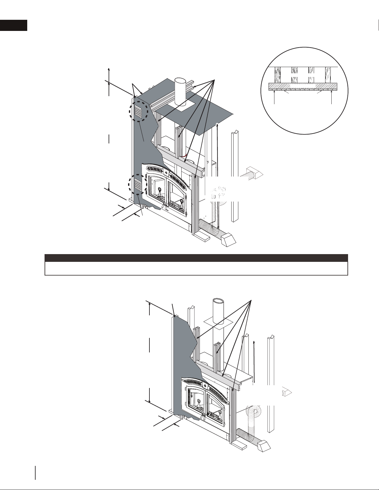
ENCLOSURE CEILING
METAL STUDS
FLOOR JOISTS
CEMENT BOARD
MINIMUM 7' (2.1m) TO BASE OF THE FIREPLACE
framing
6.1 when using a solid pack chimney
Cement board and steel studs
on enclosure ceiling not
required above 10' (3.1m)
Cement board
Metal Studs
Face must have a
minimum 8' (2.4m)
height of cement
board depending
upon ceiling height
Combustible
Fig. 1
facing and wood
framing may start
The appliance face and
enclosure ceiling must
be framed using 2x4
metal studs.
at 8' (2.4m) above
the base of the unit
6" (152mm)
Cement board from
the side of the unit
to combustibles
ceiling metal studs, both
Fig. 2
Face and enclosure
Enclosure ceiling
'
height from 7
to 10
(2.1m)
'
(3.1m)
The minimum enclosure
ceiling height is 7 feet
(2.1m).
Non-combustible
materials (cement board
and metal studs) must
be used.
clad with cement board
note:
For more information on ventilation openings (Fig. 1 and Fig. 2), see "ventilation openings" section.
6.2 when using an air cooled chimney
Face must have a
minimum 7' (2.1m)
height of cement board
Combustible
facing and wood
framing may start
at 7' (2.1m) above
the base of the unit
6" (152mm)
Cement board from
the side of the unit
22
W415-1501 / E / 12.17.18
to combustibles
Cement board
Facing on metal studs,
clad with cement board
Metal Studs
Minimum
enclosure ceiling
height 7' (2.1m)
Page 23
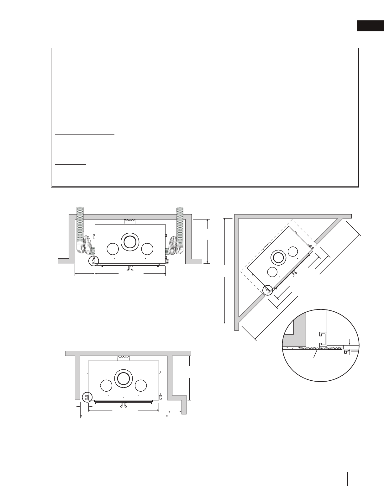
6.3 minimum clearance to combustibles
1/2" (13mm) Cement
board finishing
A
Framed Enclosure
Rear - 0" (0mm) to stand-offs (rear)
Sides - 6" (152mm) to sides
Ceiling - 120" (304.8cm) from the base of the appliance (unless shielded
(enclosure) with metal studs and cement board)
Ceiling - 84" (213.4cm) from the base of the appliance
(in front of appliance)
Chimney - 2" (51mm) (follow manufacturers instructions)
Hot air Gravity Ductwork Insulation - 1" (25mm)
Solid Pack Chimney
Ceiling - 120" (304.8cm) from the base of the appliance (unless shielded
(enclosure) with metal studs and cement board).
Air Cooled
Ceiling - 84" (213.4cm) from the base of the appliance
(enclosure)
6.4 minimum enclosure clearances
framing
EN
30 3/4"
(781mm)
15” (381mm)
required if
coiling liner
50" (1270mm)
Shown with air intake liner coiled to create a cold trap.
OR
A minimum of 6" (152mm) is required to combustibles from
the side of the appliance. This is only if the intake liner is
routed below the 2" (51mm) projection of the outer casing
of the appliance. If the intake liner is routed vertically along
the side of the appliance then a spacing of 7" (178mm) is
required.
30 3/4"
(781mm)
6"
(152mm)
MIN
50" (1270mm)
61 1/2" (1562mm)
21"
(533mm) MIN
87"
(2210mm)
50" (1270mm)
" (1562mm)
2
/
1
61
123" (3124mm)
2 layers of 1/2" (13mm)
cement board needed to fi ll
gap A.
When framing in appliance, allow for fi nishing material thickness.
W415-1501 / E / 12.17.18
23
Page 24
EN
framing
6.5 minimum mantel clearances
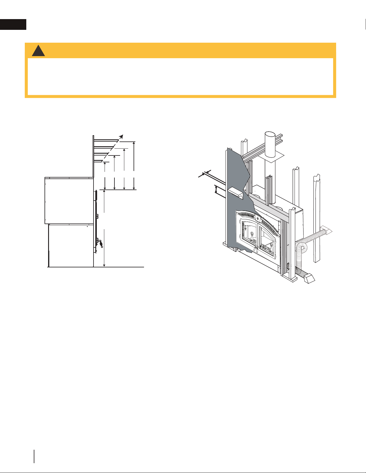
!
WARNING
• Risk of fi re!
• Maintain all specifi ed air space clearances to combustibles. Failure to comply with these instructions may cause
a fi re or cause the appliance to overheat. Ensure all clearances (i.e. back, side, top, vent, mantel, front, etc.) are
clearly maintained.
• When using paint or lacquer to fi nish the mantel, the paint or lacquer must be heat resistant to prevent
discolouration.
An optional combustible mantle must be a minimum of 12" (30.5cm) above the top of the faceplate and not to
extend more than 2" (51mm) from the surface. See chart below for further information.
A
A = 8" (203mm)
B= 6" (152mm)
C= 4" (102mm)
D= 2" (51mm)
B
C
D
EFGH
E = 12" (305mm)
F= 14" (356mm)
G= 16" (406mm)
H= 18” (457mm)
2" (51mm)
TOP OF
FACEPLATE
(KEYSTONE)
43"
(1092mm)
12" (305mm)
24
W415-1501 / E / 12.17.18
Page 25

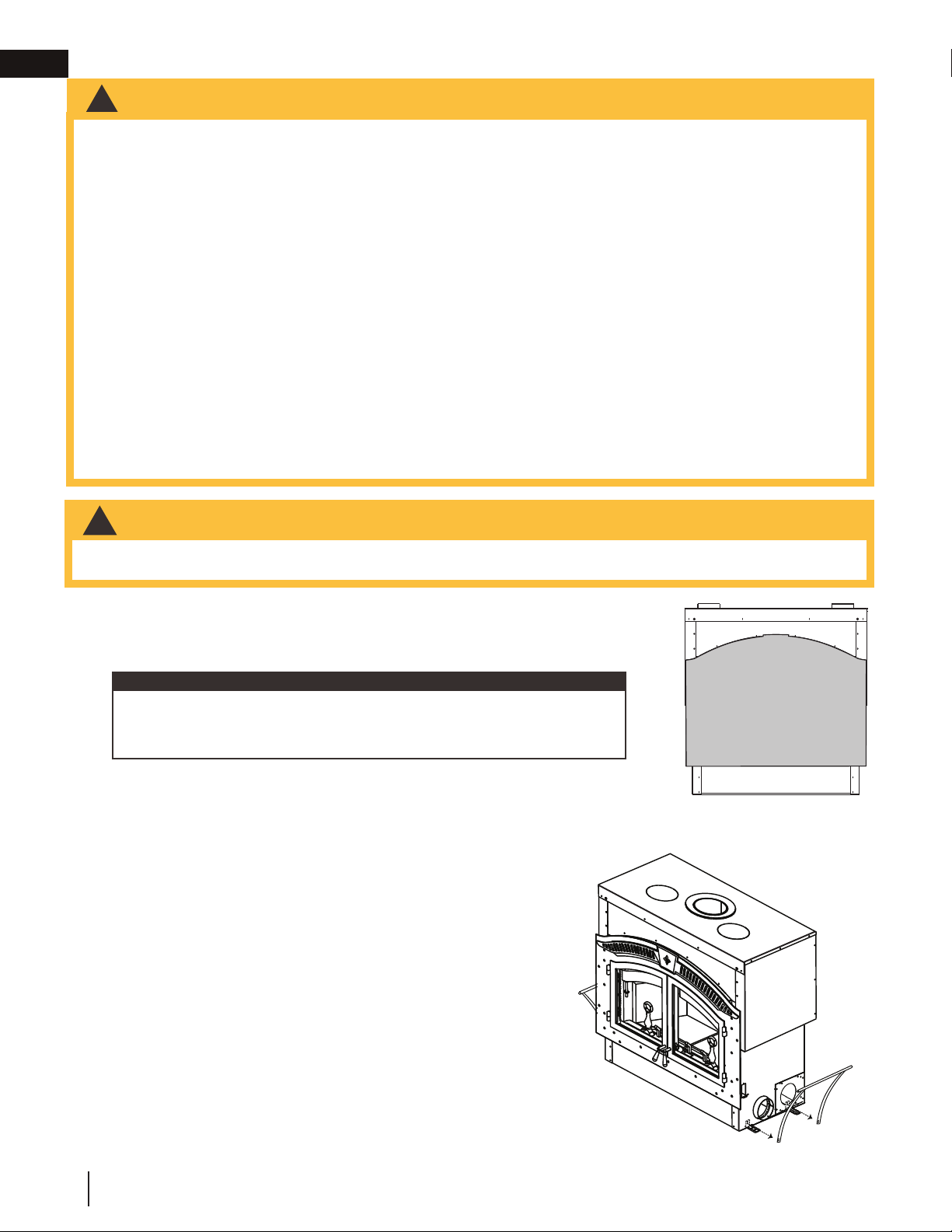
7.0 fi nishing
!
WARNING
• Use only a non-combustible material to fi nish the face of the appliance. A non-combustible material such as
cement board is required for this purpose.
• Ventilation openings are required in enclosures up to 96" (243.8cm) high. They are recommended for all
enclosures.
• Above 84" (213.4cm), combustible fi nishing materials may be used on the front face.
• Do not insulate around the appliance.
7.1 faceplate
A. Remove the facing template held in place with
the 12 screws shown.
B. Discard the screws and template.
EN
7.2 upper grill installation
A. Mount the keystone and upper grill to
the faceplate as shown, using the 4 nuts
supplied.
B. Remove the backing and place logo onto the
bottom left corner of the faceplate.
tip:
Record your serial number in the manual for quick
future reference.
7.3 keystone installation
A. Secure the faceplate to the appliance, using
the 12 screws supplied.
B. Start all 12 screws, then tighten evenly.
Logo
Placement
W415-1501 / E / 12.17.18
25
Page 26

EN
fi nishing
7.4 door handle installation
RIGHT DOOR HANDLE (OPERATING)
A. Insert the door rod through the round hole
of the latch, ensuring the fl at edge of the
D-shaped hole points towards the hinges.
B. Slide the end of the door rod through the
bushing at the top of the door, as shown.
C. Insert the handle shaft through the door and
latch.
D. Secure with 2 fl at washers and a nut.
E. Feed the handle through the handle spacer
and into the handle shaft.
note:
You may need to move washers to the other side of
the latch to obtain suffi cient door seal.
LEFT DOOR HANDLE (FIXED)
A. Insert the handle shaft through the door.
B. Secure with a lock washer, 2 fl at washers, and
a nut.
C. Feed the handle through the handle spacer
and into the handle shaft.
note:
The fi nal angle of the left door handle should mirror
the right door handle in the closed position. Tighten
the nut to secure the left handle at the desired angle.
Flat side of
“D” shape
Latch
Door
Rod
Nut
Flat
Washers
Handle
Spacer
Handle
Bushing
Flat side of
“D” shape
Handle
Shaft
Flat side
of “D”
shape
Handle shaft
Handle Spacer
Handle
Nut
Flat Washers
Lock
Washer
7.5 door installation
A. Place brass washers onto the faceplate hinge bushing.
note:
2 extra washers are supplied in order to level the doors if
needed.
B. Slide the door hinge pin into the faceplate hinge bushing.
C. To remove the doors, open them slightly and lift them out
of the faceplate hinge bushings.
26
W415-1501 / E / 12.17.18
Page 27

7.6 door latch installation
The door latch is adjusted by moving the washer from one side of the latch to the other. Tighten the outer nut to
secure the latch.
CROSS-SECTION OF
DOOR & GLASS
fi nishing
EN
Door Latch Rod
Door Latch Rod
Inner Nut
1/2" (12.7mm)
Wrench
Threaded portion
of handle
7.7 secondary air tube removal / installation
Place the gasket and the secondary air tube W010-1594
against the rear of the firebox onto the studs and secure
using brass nuts.
Door
Frame
Door
Handle
Glass
Glass
Gasket
W415-1501 / E / 12.17.18
27
Page 28
EN
fi nishing
7.8 fi rebrick and baffl e installation
!
WARNING
• Operation of the appliance without the baffl es can result in excessive temperatures that could damage the
appliance, chimney, and the surrounding enclosure.
The by-pass damper should be in the "OPEN" position when using the spark screen, during start-up, when loading fuel and in warmer months where less heat is preferred.
The by-pass damper should be in the "CLOSED" position when the doors are closed and proper chimney draw is
established.
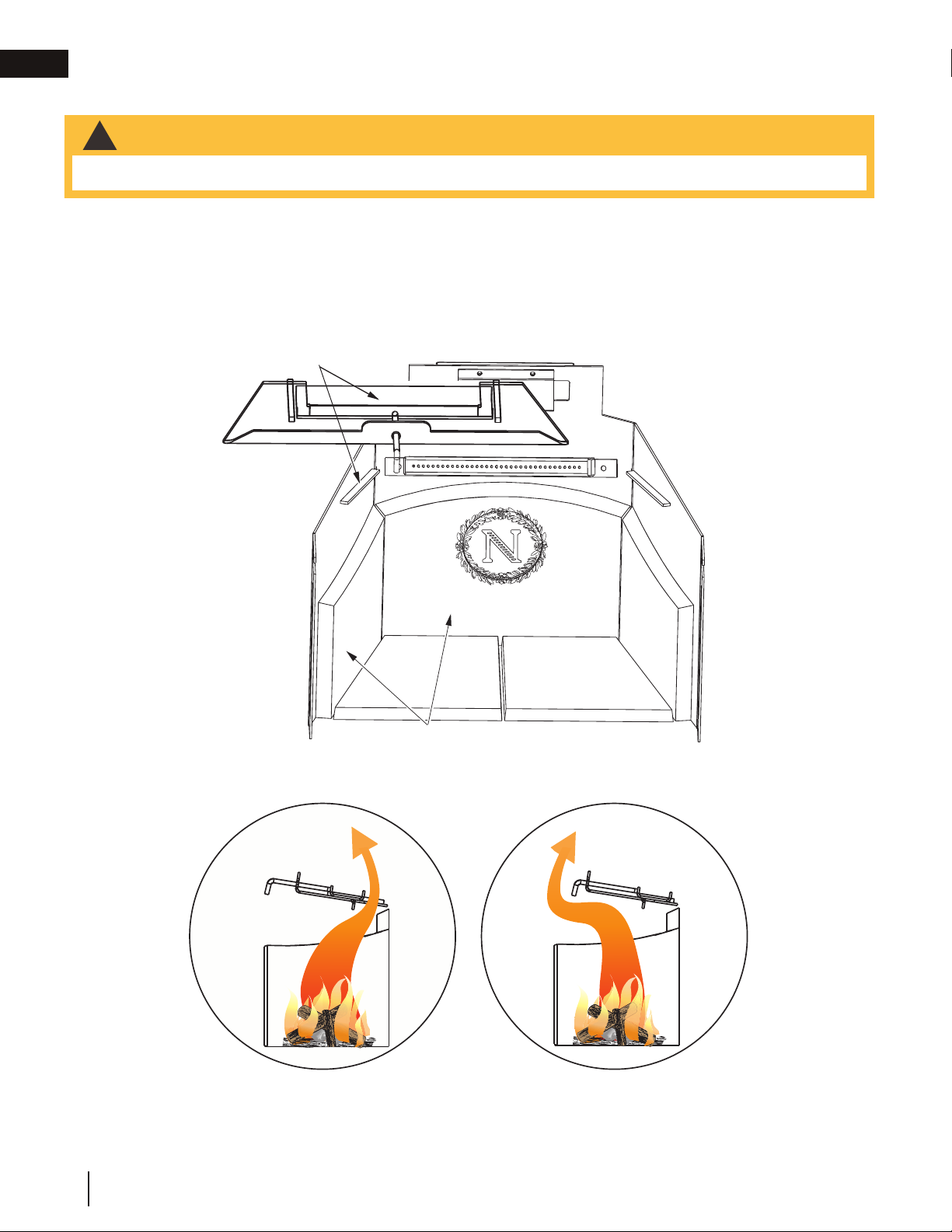
Place the by-pass damper
on the supports at the rear
and sides of the firebox.
Place the side and rear firebricks against the wall.
For easy start up open the by-pass damper.
SIDE VIEW
BY-PASS IN “OPEN” POSITION
SIDE VIEW
BY-PASS IN “CLOSED” POSITION
28
W415-1501 / E / 12.17.18
Page 29
fi nishing
12
3
/
8
"
(314.3mm)
OUTSIDE WALL
INSIDE WALL
LEVEL SURFACE
BLOWER HOUSING
10
1
/
2
"
(266.7mm)
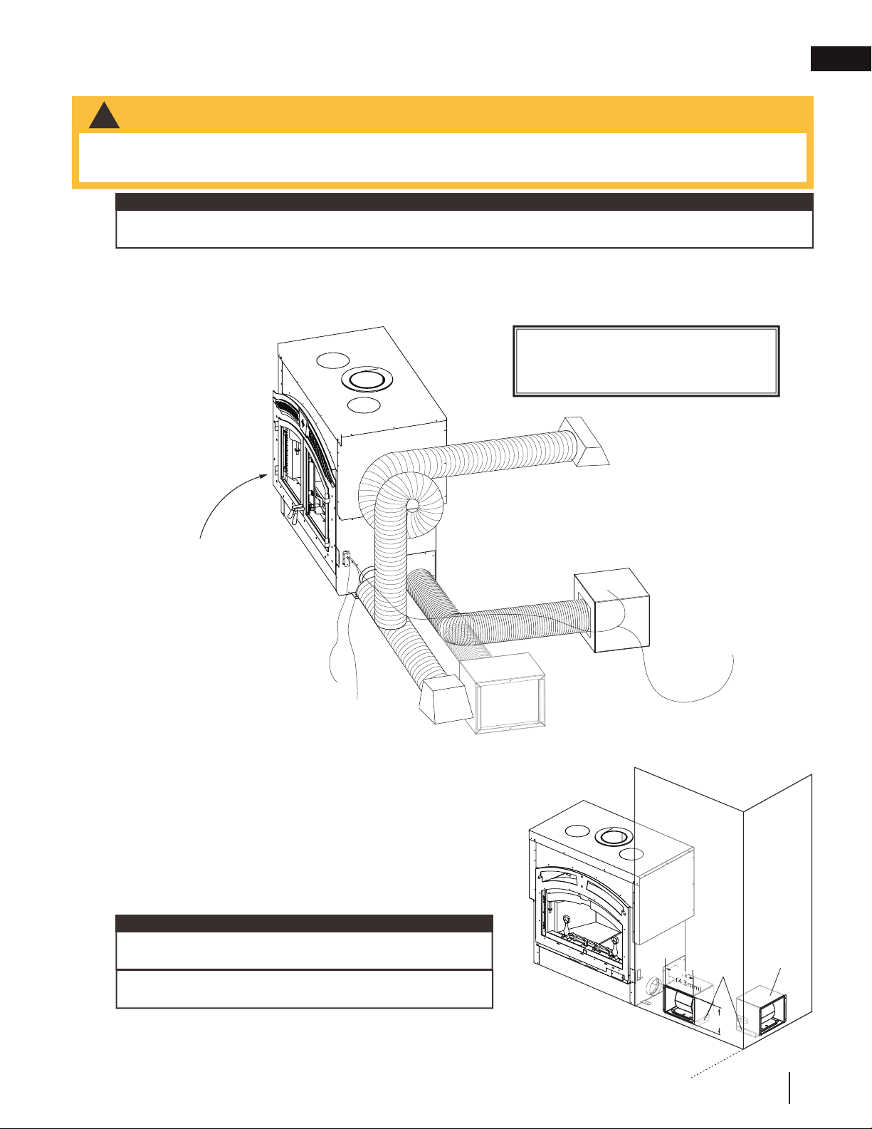
7.9 optional NZ64 blower installation
!
WARNING
• All wiring should be done by a qualifi ed electrician and shall be in compliance with local codes and with the
National Electric Code ANSI/NF No. 70-Current (in the United States), or with the current CSC22.1 Canadian
Electric Code (in Canada).
note:
Consideration should be made for blower location as the closer to the appliance, the greater the air fl ow noise
will be. Blower may be installed on either side of the appliance.
Route a 120 Volt, 60Hz electrical supply (not supplied) from the electrical box on the side of the appliance to the
electrical box on the blower housing.
The appliance comes complete with a safety switch and a thermally activated switch.
FOR COMPLETE INSTRUCTIONS,
SEE BLOWER KIT.
Blower housing may
be installed on an
outside wall to bring
in fresh air for hot air
circulation (not
Blower may be installed
on either side of the unit
10' (3.1m) length
of venting supplied
recommended in
colder climates)
Housing must be
mounted
horizontally
EN
L1
L2
Optional summer fan
switch (not supplied)
A. Remove the template.
B. Position the blower to an inside or outside wall into
3
a framed opening 12
/8” (314mm) wide by 10 1/2”
(267mm) high. (Outside wall not recommended in colder
climates as cold air may be drawn into the house when
the appliance is off.)
note:
The blower housing should be installed onto a level surface
large enough to support the blower assembly.
Allow for fi nishing material when securing the blower housing, as the grill mounts to the housing.
Blower housing may be
installed inside a home
that has sufficient air flow.
W415-1501 / E / 12.17.18
29
Page 30
EN
JUNCTION
BOX COVER
UNIT
JUNCTION
BOX
fi nishing
C. Connect the 6” (152.4mm) collar to the blower opening located on the side of the appliance. An optional
Use sealant to ensure that the connection is air tight.
opening is covered on the other side of the appliance. If this location is preferred, switch the cover plate
and collar. Secure by reaching through the collar and bending the tabs.
note:
We recommend installing the blower in a different room or
even different level of the house. This will generate great
air movement and improve the distribution of the warm air
coming from the appliance.
D. Electrical Connection
I. Remove the junction box covers on the
appliance and the blower.
II. Removing the junction box cover on the
appliance exposes 4 black, labeled wires:
• 2 wires labelled "by-pass": go to by-pass
(summer) switch (not supplied - overrides the
thermally activated switch enabling the user to
run the blower without heat).
important:
Marrett by-pass (summer) switch wire leads separately (do not connect together) if the by-pass switch
is not desired.
• 1 wire labelled "blower": connects to KB-35
rheostat (not supplied) and then fan-speed
control blower wire connects to white blower
wire.
• 1 wire labelled "L1": connects to power (hot
lead).
III. Removing the junction box cover on the
blower exposes 3 coloured wires:
• 1 black wire: connects to power "L2" (neutral
lead).
• 1 green wire: connects to ground.
• 1 white wire: connects to fan-speed control
rheostat (not supplied) (see above).
SUMMER
SWITCH
GROUND
GREEN
2 BY-PASS WIRES
WHITE
KB35
RHEOSTAT
not supplied
BY-PASS
(SUMMER)
SWITCH
NOT SUPPLIED
THERMODISC
(RHEOSTAT {VARIABLE SPEED SWITCH})
FAN-SPEED CONTROL
or WALL SWITCH or THERMOSTAT
NOT SUPPLIED
BLOWER
PRESSURE
L2 [ NEUTRAL ]
BLACK
L1 [ HOT ]
SWITCH
FAN
L1
G
L2
30
W415-1501 / E / 12.17.18
Page 31

fi nishing
GRILLE
FILTER
ALLOW FOR
THICKNESS
OF FINISHING
MATERIAL
INSTALL THE KB35
AND BY-PASS
SWITCHES IN A
CONVENIENT
LOCATION
INSTALL THE KB35
AND BY-PASS
SWITCHES IN A
CONVENIENT
LOCATION
E. Connect the 6” (152mm) liner to the appliance and blower collars. Secure using 3 screws on each end
and seal with caulking.
Liner supplied stretches to a maximum of 10’ (3.1m).
F. Insert the fi lter into the grill. Foam gasket [1/2” (13mm) weather stripping] between the grill and blower
housing is recommended, but not supplied.
The blower fi lter is washable.
G. The bottom lip of the grill latches over the bottom lip of the housing. Use 2 screws to secure the top of
the grill to the facing.
EN
7.10 NZ150-KT kit
The circulation air inlet pipe must terminate outside of the
appliance enclosure to ensure proper air fl ow around the
fi rebox.
The 6" (152mm) circulation air inlet pipe may be connected to
either the NZ64 blower kit or the NZ150-KT kit.
Avoid terminating higher than the bottom of the doors on the
appliance to prevent air fl ow reversal.
An optional opening is covered on the other side of the
appliance. If this location is preferred, switch the cover plate
and collar.
7.11 NSK6 optional screen kit
Use the screen when you are in the room to enjoy the ambience of an open, wood crackling fi re.
Medium sized wood loads should be used to prevent logs from rolling against the screen.
Chimney action may not allow the screen to be used in some installations due to the resulting smoke spillage.
Opening the by-pass damper may help prevent smoke spillage. Wood will burn at a faster rate and heat
output will be less with the screen compared to the stove operation with the glass doors closed.
W415-1501 / E / 12.17.18
31
Page 32

EN
fi nishing
7.12 smoke shelf
To reduce smoke spillage due to a poor chimney draft, the NZ6000-1 can be equipped with a smoke shelf extension.
note:
The smoke shelf is only used when burning with the door open to prevent smoke spillage back into the room.
AIR WASH PLATE
SMOKE SHELF
EXTENSION
32
W415-1501 / E / 12.17.18
Page 33

8.0 selecting wood
WARNING
!
• This appliance is designed to burn natural wood only. Do not burn treated wood, coal, charcoal, coloured
paper, cardboard, solvents or garbage. This appliance has not been tested with an unvented gas log set. To
reduce risk of fi re or injury, do not install an unvented gas log set into the appliance.
• Higher effi ciencies and lower emissions generally result when burning air dried seasoned hardwoods, as
compared to softwoods or too green or freshly cut hardwoods.
• Burning wet unseasoned wood can cause excessive creosote accumulation. When ignited, it can cause a
chimney fi re that may result in a serious house fi re.
• Do not store fuel within the clearance to combustibles, or in the space required for re-fueling and ash removal.
Before loading the appliance, ensure all required insulation and baffl es (if equipped) are installed and situated
properly. For maximum effi ciency, when the appliance is thoroughly hot, load it fully to the specifi ed maximum
amount and burn at a medium low setting (if equipped). The whiteness of the bricks and the cleanliness of the
glass are good indicators of your operating effi ciency. Not enough heat is produced when only a few pieces of
wood are burned or the wood may not burn completely.
note:
Appliances surrounded by solid rock or brick will experience a longer heat up period as those materials
absorb the heat being generated.
TYPES OF WOOD
Both hardwood and softwood burn
equally well in this appliance but
hardwood is denser, will weigh more per
cord and burn a little slower and longer.
Manufactured fi relogs made by
compressing 100% natural wood fi bre
can be safely used as fuel. Do not use
manufactured fi relogs if they contain
additives such as paraffi n, wax, binders
etc. Never burn more than two manufactured fi relogs at a time.
MOISTURE CONTENT
Burn only dry, clean unpainted wood that has been seasoned. It produces more heat and less soot or
creosote. Freshly cut wood contains about 50% moisture while after proper seasoning only about 20% of the
water remains. As wood is burned, this water boils off consuming energy that should be used in heating. The
wetter the wood, the less heat is given off and the more creosote is produced. Dry fi rewood has cracks in the
end of the grain.
STORING WOOD
Firewood should be split and stacked in a manner that allows for full air circulation and covered in early spring
to be ready for burning that fall. Dry fi rewood has cracks in the end grain.
Cut the wood so that it will fi t horizontally, front to back, making for easier loading and less of a likelihood that
the wood will roll onto the glass.
Fuel for the appliance must not be stored closer than the required clearances to combustibles (heat sensitive
material). NEVER STORE WOOD IN THE ASH PAN COMPARTMENT (if applicable).
EN
W415-1501 / E / 12.17.18
33
Page 34

EN
9.0 operation
Expansion / contraction noises during heating up and cooling down cycles are normal and to be expected.
TIPS FOR BURNING:
• Create a large fi re to heat up the appliance before closing bypass door and adjusting to a slower burn.
• To create a large, quick burning fi re, use small pieces of wood.
• For a lower, but, extended burn, stack larger pieces of wood close together.
• For long burns, leave a 1” (25mm) - 2” (51mm) bed of ashes.
• Burn dry wood only.
• With the exception of overnight burns, create large, quick burning fi res whenever possible. Smaller, slow
burning fi res using large logs will cause the glass to become dirty. Larger, quick burning fi res using medium
sized wood to refuel frequently are much more effi cient.
• It is important to minimize visible smoke emitting from the chimney. Burning seasoned fi rewood, maintaining
the appliance catalyst and following the operating instructions contained within this manual will ensure that
visible smoke emissions are minimized.
DO’S
• Verify with a moisture meter that wood contains no
more than 20% moisture content.
• Burn several pieces of medium sized wood as they
are better than a few big pieces.
• Clean chimney regularly.
• Refuel frequently using medium sized wood.
• “Fine tune” the air settings (if applicable) for optimum
performance.
9.1 operating sounds and smells
If a blower is installed, slight humming sound may be heard depending on the location of the blower. The sound may
be minimized by turning down the blower speed. It is also normal during operation to hear creaking and/or ticking
sounds as the metal plate components of the appliance expand and contract. This may be present during both
warm up and cool down periods.
During the break-in period (the fi rst 2 or 3 fi res) create only small, hot fi res using kindling. This will allow the fi rebrick
to cure. Do not be alarmed if small hairline cracks develop in the fi rebrick. This is a normal occurrence and does not
pose a safety hazard. During this time the paint may also emit an odour as it cures and you may wish to open a door
or window to alleviate the smell.
There are many different ways to start a fi re, review the hints and warnings in this section to ensure the fi re is started
properly.
DONT’S
• Take ash out immediately. Let it accumulate to a
depth of at least one inch. A good ash layer provides
for a longer lasting and better burning fi re.
• Burn wet wood with more than 20% moisture
content.
• Close the door too soon or damper down too
quickly.
• Burn one large log rather than two or three smaller
sized logs.
• Burn at continually “low setting” (if applicable), if
glass door is constantly blackened. This means the
fi rebox temperature is too low.
9.2 fi re extinguishers, smoke detectors and carbon monoxide detectors
!
WARNING
• This appliance emits carbon monoxide (CO), a colourless and odourless gas that can lead to severe illness and
even death if exposed to human or animals in suffi cient quantities.
• The use of this appliance in a manner inconsistent with the operating instructions contained in this manual can
signifi cantly increase the emission of smoke and carbon monoxide (CO). Therefore, we recommend you install
detectors in areas that could be susceptible to carbon monxide (CO).
All homes with a solid fuel burning appliance should have at least one fi re extinguisher in a central location,
known to all, at least one smoke detector and carbon monoxide (CO) detector in the room containing the
appliance. If the smoke detector sounds an alarm, correct the cause but do not deactive or relocate the smoke
detector. If the carbon monoxide detector sounds an alarm, immediately vent the area, evacuate and call your
local fi re department.
34
W415-1501 / E / 12.17.18
Page 35

9.3 establishing draft
!
WARNING
• Always operate this appliance with the door closed and latched except during start-up and re-fueling.
note:
Remove all sources of gasoline or other fl ammable vapours and liquids in the vicinity of this or other appliances
prior to lighting.
operation
EN
To reduce smoking when starting the appliance, roll up
some newspaper, place it near the appliance fl ue and light
it until chimney begins to draw.
When a fi re has been established and it is necessary to
reload or adjust the fuel, open the doors slowly to avoid
drawing smoke into the room.
A properly installed Napoleon appliance should not smoke.
If yours does, check the following:
• Has the chimney had time to get hot?
• Are the air intake hoods blocked or closed?
• Is the smoke passage blocked anywhere in the appliance or chimney?
• Is the smoke fl ow impeded by too long a horizontal pipe or too many bends?
• Is it a weak draft perhaps caused by a leaky chimney, a cold outside chimney, too short a chimney, or a
chimney too close to trees or a higher roof?
W415-1501 / E / 12.17.18
35
Page 36

EN
operation
9.4 fuel loading and burn cycle
!
WARNING
• Burn wood behind the log retainer directly on the fi rebricks. Do not use elevated grate or otherwise raise the fi re.
• Do not store wood within appliance installation clearances or within the space required for re-fueling and ash
removal.
• Burning wet, unseasoned wood can cause excessive creosote accumulation, which, when ignited, can cause a
chimney fi re that may result in a serious house fi re.
• It is recommended to use heat-resistant gloves and/or metal log tongs when reloading this appliance.
When operating the appliance effi ciently, the bricks will be nearly all white and the glass mostly clear. The whiteness of the bricks and the cleanness of the glass are good indicators of your operating effi ciency.
Not enough heat is produced when only one or two pieces of wood are burned.
A minimum of three pieces are needed to encase a bed of coals that sustains the fi re. Loosely stacked wood
burns quicker than a tightly packed load.
A fl ash fi re is a small fi re burned quickly when you don’t need much heat. After your kindling has “caught”, load
at least 3 pieces of wood, stacked loosely. Burn with the draft control fully open or closed only slightly.
Wood burns in cycles rather than giving a steady output of heat. It is best to plan these cycles around your
household routine so that only enough coals are left to start the next load.
Burn only dry seasoned wood. It produces more heat and less soot or creosote. Do not burn ocean beach wood,
as its salt content can be corrosive to metal.
36
SUFFICIENT FIREWOODINSUFFICIENT FIREWOOD
When refuelling, open the door slowly to prevent smoke spillage. Use a pair of long appliance gloves when
feeding the fi re. Keep a small steel shovel nearby to use as a poker and to remove ashes. Do not store wood
within 4 feet (1.2m) of the appliance.
Follow the directions below to minimize smoke spillage while re-loading the appliance.
A. Open the door(s) slightly. Allow the airfl ow inside the fi rebox to stabilize before opening the door(s)
fully.
B. Load wood and close doors, leaving slightly ajar.
C. After 5 to 10 minutes, close the door(s) completely.
note:
Differences in chimney height and draft may lower overall burn times.
DO NOT OVERFIRE THE APPLIANCE! Overfi ring occurs by burning large amounts of smaller wood pieces or
vigorously burning large loads of wood for long periods of time (more than one or two hours). Over-fi ring can lead
to fi re hazards and/or injuries.
W415-1501 / E / 12.17.18
Page 37

operation
9.5 starting the fi re
WARNING
!
• Always operate this appliance with the door closed and latched except during start up and re-fueling or
unless otherwise noted with compatible Wolf Steel approved accessories. Burning your appliance with the
doors open or ajar creates a fi re hazard that may result in a house and/or chimney fi re. Always wear gloves to
prevent injury. Do not leave the fi re unattended when the door is unlatched or when using a spark screen as
unstable wood could fall out of the fi re chamber creating a fi re hazard to your home.
• Never leave children unattended when there is a fi re burning in the appliance.
• Never use gasoline-type lantern fuel, kerosene, charcoal lighter fl uid, or similar liquids to start or “freshen up” a
fi re in this appliance. Keep all such liquids well away from the appliance.
• This appliance has not been tested with any vented or unvented gas log set. To reduce risk of fi re or injury, do
not install a vented or unvented gas log set into this appliance.
Remove all source of gasoline or other fl ammable vapours and liquids in the vicinity of this or other
appliances prior to lighting.
Use plenty of newspaper and kindling to ensure the appliance quickly reaches a proper temperature. Once the
kindling is burning rapidly, place a few larger pieces of wood onto the fi re.
Tip: When fi rst lighting a fi re, if the smoke is not quickly drawn into the chimney, there may be a downdraft or cold
air in the chimney. By fi rst burning large amounts of crumpled newspaper, the chimney will get heated and the smoke
will quickly vent up the chimney.
EN
To start, a brisk fi re is required.
A.
Roll up some newspaper (loosely
crumpled), light it and place it near
the appliance fl ue until the chimney
begins to draw.
Draft is the force which moves air from the appliance up through the chimney. The amount of draft in your chimney
depends on the length of the chimney, local geography, nearby obstructions and other forces.
Inadequate draft may cause back-puffi ng into the room and may cause plugging of the chimney. Too much draft may
cause an excessive temperature in the appliance, glowing red appliance parts or an uncontrollable burn which can all
lead to a chimney fi re or a permanent damage to the appliance.
B. Cover with dry kindling. C. Light the paper and when the
Light the paper and leave
kindling is burning add more fuel.
the door slightly ajar (one to
two inches) until all kindling is
burning.
W415-1501 / E / 12.17.18
37
Page 38

EN
operation
D. To maintain a brisk fi re, a hot
coal bed must be established
and maintained.
When a fi re is burning, open the doors slowly to avoid drawing smoke into the room.
Closing the doors too quickly after refuelling will reduce the fi rebox temperature and may result in an
unsatisfactory burn.
G. As soon as the doors are closed, you will observe a change in
the fl ame pattern. The fl ames will get smaller and lazier because
less oxygen is getting into the combustion chamber. The fl ames,
however, are more effi cient. The fl ames will remain lazy but
become larger again as soon as the fi rebricks have been heated
thoroughly and the chimney becomes heated and provides a good
draft.
H. With the doors opened, the fi re is wastefully drawing heated room
air up the chimney which is certainly not desirable. Always operate
with the doors fully closed once the medium sized logs have
caught fi re.
You can now add larger pieces of wood and operate the appliance
normally. Once the appliance is entirely hot, it will burn very
effi ciently with little smoke from the chimney. There will be a bed of hot
coals in the fi rebox so you can safely fi ll the fi rebox with wood to the top
of the andirons.
Can't get the appliance operating? Use more kindling and paper.
Assuming the chimney and vent are sized correctly and there is suffi cient
combustion air, the lack of suffi ciently dry quantities of small kindling is the
problem. Thumb size is a good gauge for small kindling diameter.
Can't get heat out of the appliance? One of two things may have
happened. The appliance door may have been closed prematurely and
the appliance itself has not reached optimum temperature.
Re-open the door and/or draft control to re-establish a brisk fi re. The other
problem may have been wet wood. The typical symptom is sizzling wood and
moisture being driven from the wood.
The only accurate way to determine wood moisture is with a moisture meter.
Contact your local dealer for more information.
note:
Appliances surrounded by solid rock or brick will experience a longer
heat up period as those materials absorb the heat being generated.
E. Slowly add larger wood (2x4 size
pieces). Lay the pieces lengthwise
from side to side in the hot
coal bed with a shallow trench
between, so that the primary air
can fl ow directly into this trench
and ignite the fuel above.
F. When the fi re seems to be at its
peak, medium sized logs may
be added. Once these logs have
caught fi re, carefully close the
doors.
OPERATING WITH DOOR CLOSED
OPERATING WITH DOOR OPEN
38
W415-1501 / E / 12.17.18
Page 39

9.6 smoking
A properly installed appliance should not smoke. If yours does, check the following:
• Has the chimney had time to get hot?
• Is the smoke passage blocked anywhere in the appliance, chimney connector or chimney?
• Is the room too airtight and the air intake not connected to the outside? Try with a window partly open.
• Is the smoke fl ow impeded by too long a horizontal pipe or too many bends?
• Is it a weak draft perhaps caused by a leaky chimney, a cold outside chimney, too large a diameter of a
chimney, too short a chimney, or a chimney too close to trees or a higher roof?
• Is the moisture content of the wood greater than 20%?
• If equipped, has the catalyst bypass been closed or closed prematurely?
operation
EN
W415-1501 / E / 12.17.18
39
Page 40

EN
10.0 maintenance
10.1 ash removal procedures
!
WARNING
• Improper disposal of ashes results in fi res. Do not discard ashes in cardboard boxes, dump in back yards, or
store in garages.
• If using a vacuum to clean up ashes, be sure the ashes are entirely cooled. Using a vacuum to clean up warm
ashes could cause a fi re inside the vacuum.
A bed of ashes approximately 1" (25mm) deep should be left on the fi rebox
bottom to help maintain a hot charcoal bed. When the fi re has burned down
and cooled, remove any excess ashes. To remove the ash, follow the directions
below.
A. After the last coal has extinguished, let the appliance cool at least
two hours.
B. Open the appliance doors.
C. Scoop the ash from the fi rebox into a metal container with a
lid. Cover the container and move the container away from the
appliance onto a suitable surface to ensure the ashes cool.
D. Dispose of the ashes.
note:
Ashes should be placed in a metal container with a tight-fi tting lid. The closed container of ashes should be
placed on a non-combustible fl oor or on the ground, well away from all combustible materials, pending fi nal disposal. If the ashes are disposed of by burial, in soil, or otherwise locally dispersed, they should be retained in the
closed container until all cinders have thoroughly cooled.
10.2 creosote formation and removal
When wood is burned slowly, it produces tar and other organic vapors, which combine with expelled moisture
to form creosote. The creosote vapors condense in the relatively cooler chimney fl ue or a slow-burning fi re. As a
result, creosote residue accumulates on the fl ue lining. When ignited, this creosote makes an extremely hot fi re.
The chimney connector and chimney should be inspected at least once every two months during the heating
season to determine if a creosote buildup has occurred.
If creosote has accumulated, it should be removed to reduce the risk of a chimney fi re.
40
W415-1501 / E / 12.17.18
Page 41

maintenance
10.3 run-away or chimney fi re
WARNING
!
• A chimney fi re can permanently damage your chimney system. This damage can only be repaired by replacing
the damaged component parts. Chimney fi res are not covered by the lifetime limited warranty.
CAUSES:
• Using incorrect fuel, or small fuel pieces which would normally be used as kindling.
• Creosote build up in chimney.
• Leaving the door ajar too long and creating extreme temperatures as the air rushes in the open door.
• If equipped, burning your appliance with the ash plug not securely seated.
SOLUTIONS:
• Do not burn treated, painted, artifi cial, paper or processed wood logs, coal, charcoal, coloured paper or
cardboard.
• Have chimney regularly cleaned.
• Be careful not to over-fi re the appliance by leaving the door open too long after initial start-up. A
thermometer on the chimney connector and/or appliance top helps to indicate the appliance operating
temperature.
• If equipped, always operate the appliance with the ash plug properly installed.
IN CASE OF A CHIMNEY FIRE:
• Close glass door and air control (and damper, when equipped).
• Have a well understood plan for evacuation and a place outside for everyone to meet. Prepare to evacuate
to ensure everyone’s safety.
• Call local fi re department. Have a fi re extinguisher handy. Contact local authorities for further information on
how to handle a chimney fi re.
• After the chimney fi re is out, clean and inspect the chimney or chimney liner for stress and cracks prior to
lighting another fi re. Also check combustibles around the chimney and the roof.
EN
10.4 chimney cleaning
Both the chimney and the appliance must be inspected and cleaned if necessary at least once a year.
For serious wood burners, chimney cleaning must be done as needed to avoid chimney fi res; the venting
systems for controlled combustion appliances may need cleaning as often as once a month. These rates,
however, depend on the burning habits of the individual operating the appliance. For example, it is possible to
clog a solid fuel appliance chimney in a few days if slow, smoldering fi res are burned and the chimney is cold.
note:
Appliances burned consistently without hot fi res may result in signifi cant creosote accumulations in the
chimney.
Certain items and considerations are important in chimney cleaning:
• Proper tools should be used, including a brush specifi cally designed for chimney cleaning.
• The chimney connector and dampers as well as the chimney should be cleaned.
• The appliance’s fi rebox and baffl e system should be cleaned if needed.
• The chimney should be inspected and repairs made if needed, preferably by a qualifi ed chimney sweep
or mason.
For more information on the inspection, maintenance, or cleaning of the chimney, including method of access
through the top of the chimney, refer to the chimney manufacturer's instructions.
W415-1501 / E / 12.17.18
41
Page 42

EN
maintenance
10.5 glass and gasket replacement
!
WARNING
• Make sure that the glass and gasket are fully installed down into the glass retainer. If the glass protrudes too far
out of the retainer, the glass will shatter when the door is closed.
At the end of each burning season inspect the door gasket ensuring that it is not worn or loose. Replace with
proper fi berglass rope. The purpose of door gasketing is to seal the fi rebox. If the doors are not sealed, air leaks
into the fi rebox, creating a quick burning fi re. This situation is not desirable for overnight or extended burns.
Replace cracked or broken glass immediately. When re-installing the glass, be sure that the glass and gasket create a solid seal around door frame. Follow the instructions below for glass removal. You may require a fl at tool to
gently press the gasket between the glass and the door.
10.6 care of glass
WARNING
!
• Do not clean glass when hot! Do not use abrasive cleaners to clean glass.
If the glass is not kept clean, permanent discolouration and/or
blemishes may result. Normally a hot fi re will clean the glass. The
most common reasons for dirty glass include:
• Not using suffi cient fuel to get the appliance thoroughly hot.
• Using green or wet wood.
• Closing the draft so far that there is insuffi cient air for complete
combustion.
If it is necessary to clean the glass, buff lightly with a clean dry cloth and non-abrasive cleaner. Clean the glass
after the fi rst 10 hours of operation with a recommended appliance glass cleaner. Thereafter, clean as required.
The glass is very strong, but do not let burning fuel rest or fall against it and always close the door gently.
NEVER FORCE OR SLAM IT SHUT!
Do not operate the appliance with broken glass, as leakage of fl ue gases may result.
Contact your local authorized dealer/distributor for complete cleaning instructions.
42
W415-1501 / E / 12.17.18
WARNING
!
HOT GLASS WILL CAUSE
BURNS.
DO NOT TOUCH GLASS UNTIL
NEVER ALLOW CHILDREN TO
COOLED.
TOUCH GLASS.
Page 43

If the glass should ever crack or break while the fi re is burning, do not open the door until the fi re is out. Do not
operate the appliance until the glass has been replaced. Contact your local authorized dealer/distributor for
replacement parts. DO NOT SUBSTITUTE MATERIALS.
This appliance is factory equipped with 5mm ceramic glass. Use only replacement parts as supplied by the
appliance manufacturer. DO NOT SUBSTITUTE MATERIALS.
10.7 NZ64 blower replacement
1. Remove the grill and fi lter by removing the two securing screws.
2. Remove the nut securing the blower bracket to the housing.
3. Lift the handles to pull the blower and bracket off the stud.
4. Slide the bracket and blower out of the housing.
5. Disconnect the wire connector from the blower.
6. Remove the old blower from the bracket by removing the four
screws.
maintenance
EN
7. Secure the new blower to the existing bracket using the four
screws.
8. Slide the new blower/bracket assembly into the housing. Ensure
that the blower bracket slides into the clips at the back of the
housing on either side.
9. Push the assembly into the housing as far in as possible.
10. Secure the assembly to the housing using the nut removed in step
B.
11. Re-secure the grill by replacing the 2 securing screws.
NUT
BLOWER
BRACKET
STUD
HANDLES
HOUSING
CLIP
BLOWER/BRACKET ASSEMBLY
W415-1501 / E / 12.17.18
43
Page 44

EN
11.0 replacement parts
WARNING
!
• Failure to position the parts in accordance with this manual or failure to use only parts specifi cally approved
with this appliance may result in property damage or personal injury.
Contact your dealer for questions concerning prices and policies on replacement parts. Normally, all parts can
be ordered through your Authorized dealer / distributor.
For warranty replacement parts, a photocopy of the original invoice will be required to honour the
claim.
When ordering replacement parts always give the following information:
• Model & Serial Number of appliance
• Installation date of appliance
• Part number
• Description of part
• Finish
Parts, part numbers, and availability are subject to change without notice.
Parts identifi ed as stocked will be delivered within 2 to 5 business days for most delivery
destinations.
Parts not identifi ed as stocked will be delivered within a 2 to 4 week period, for most cases.
Parts identifi ed as ‘SO’ are special order and can take up to 90 days for delivery.
44
W415-1501 / E / 12.17.18
Page 45

replacement parts
k
k
k
k
r
k
A
Yes
EN
9
2
6
11.1 overview
5
ir supply vent (10” x 6”)
Grate
Secondary air tube
Gasket, secondary air tube
16
3
W185-0020
W385-2010 Napoleon logo
W010-1594
W290-0121
W450-0028 Nut, hex brass
16
15
* Parties non illustrées.
Yes
Yes
121114
Yes
W410-0026
13*
Part Number Description
Ref.
4
15
Stocked Stocked
12
14
Items may not appear exactly as illustrated.
11
10
Left side firebric
Bypass damper assembly
7
1
8
W090-0101 Bottom right firebric
W010-1225 Door glass and gasket
W090-0099 Rear firebric
Part Number Description
Ref.
2
1
W090-0098 Right side firebric
W090-0097
5
W010-1399
W660-0065 Heat senso
8
7
6
W090-0100 Bottom left firebric
3
4
W415-1501 / E / 12.17.18
W010-1180 Ash lip assembly
W715-0628 Andirons
9
10
45
Page 46

EN
r
K
A
A
r
T
K
T
A
T
A
V
K
YesYesY
r
12.0 accessories
es
6
5
Circulation Air Mounting Kit
120V Thermostat
3
21
4
2
24
12
W690-0005
W305-0007 Blower GrillH335-1
NZ150-K
Part Number Description
Ref. No.
7
Stocked Stocked
14*
13*1215*
Items may not appear exactly as illustrated.
6” x 10’ Outside Combustion Air Kit
W175-0002 8” Couple
NZ620-K
NZ220-2 5” x 5” Air Vent (for NZ221)
W010-0067 Gasket, Secondary Air Tube
270 Thurmalox Paint
17*
18*
19*
16*
ariable Speed Control (c/w knob)
W470-0017A Wrought Iron Paint
W062-0018 Blower - NZ64
KB-35
22*
21
20*
Door Handle - Bird Cage
010-1183 Right Door Assembly
W010-1184 Left Door Assembly
23
W410-0005 11.5” x 8” Air Vent
W325-0029
25
26*
24
46
W415-1501 / E / 12.17.18
23
1
25
11
rched Black Double Doors
rched Wrought Iron Double Doo
H335-1WI
Part Number Description
1
1
Ref. No.
rched Black Upper Inset
FPK-1 Black Surround
FPWI-1 Wrought Iron Surround
UGK
UGSC Arched Satin Chrome Upper Inset
2
2
3
Black Keystone
NSK6 Arched Screen Kit
KS
CP Country Crane and Hearth Pot
4
3
6
5
ir Cooled Chimney Kit
Smoke Shelf Extension
W250-0005 Blower Filte
NZ64 Blower Kit
NM228-M 8” Flue Tile Support
NZAC-K
NZ-SMS
8*79*
10*
11
* Parts not illustrated.
Page 47

SYMPTOM PROBLEM TEST SOLUTION
Smoke enters the room
during start-up.
13.0 troubleshooting
Cold air blockage in chimney. - Burn a piece of newspaper to establish a draft.
EN
Kindling does not start fi re smolders.
Smoke enters the room
while re-loading.
Appliance does not burn
hot enough.
Blower does not run. Appliance is not up to tem-
Faceplate is cold. This is normal. - The air leading into the fi rebox could come from the
Appliance does not burn
overnight.
Appliance smoking. - Has the chimney had time to get hot?
Cold air blockage in chimney. - Burn a piece of newspaper to establish a draft.
Not enough starter paper. - Use additional newspaper if necessary.
Not enough air. - Open doors a small crack.
Insuffi cient draft. - Chimney height and outside conditions can negatively
affect draft. In these cases a small amount of smoke
may enter the home. Adding more pipe may help.
- Clean chimney
Wood is wet. - See the section on “Selecting Wood” for details.
Insuffi cient draft. - Chimney height and outside conditions can negatively
affect draft. In these cases a small amount of smoke
may enter the home. Adding more pipe or a draftinducing cap may help.
- Clean chimney.
- This is normal. The blower will come on when the
perature.
Electricity is cut to the blower. - Check the household breaker or fuse to make sure it is
Door is ajar. - Appliance door must be closed for blower to operate.
The doors are not sealing. - See the section “Door / Gasket Replacement” for
appliance is heated up enough to heat the room.
operable.
exterior. In these cases this air comes into the fi rebox
and exits the chimney. This will not damage the
appliance.
details.
- Is the smoke passage blocked anywhere in the
appliance or chimney?
- Is the smoke fl ow impeded by too long of a horizontal
pipe or too many bends?
- Is it a weak draft perhaps caused by a leaky chimney,
a cold outside chimney, too short a chimney, or a
chimney too close to a tree or a higher roof?
W415-1501 / E / 12.17.18
47
Page 48

EN
14.0 warranty
Napoleon
Napoleon
pride in their work. The complete appliance is again thoroughly inspected by a qualifi ed technician before packaging to ensure
Wood Appliances are manufactured under the strict Standard of the world recognized ISO 9001 : 2015 Quality
products are designed with superior components and materials assembled by trained craftsmen who take great
Management System.
that you, the customer, receives the quality product that you expect from Napoleon.
Napoleon Wood Appliances President’s Lifetime Limited Warranty
48
The following materials and workmanship in your new
as you own the appliance. For pellet appliances this covers: the pellet hopper, outer shell, ceramic glass (thermal breakage
only) and ash drawer.* For wood appliances this covers: combustion chamber, heat exchanger, stainless steel baffl e
retainer, ceramic glass (thermal breakage only), gold plated parts against tarnishing, porcelainized enameled components,
aluminum extrusion trims, vortex baffl es, ash drawer and iron castings.*
For pellet appliances, the combustion chamber and heat exchanger are warranted against defects for a period of 5 years.
For wood appliances equipped with a guillotine door/screen system, they are warranted against defects for a period of 5 years.
Electrical (110V) components and wearable parts are covered and
during the fi rst year of the limited warranty. For pellet appliances this covers: blowers, thermal switches and burn pot.* For
wood appliances this covers: blowers, thermal switch, switches, wiring, fi rebrick, secondary air tubes and gasketing.*
Labour related to warranty repair is covered free of charge during the fi rst year, with the exception of the guillotine door/
screen system which will be warranted for a period of 3 years. Repair work, however, requires the prior approval of an
authorized company offi cial. Labour costs to the account of
any repair work must be done through an authorized
For appliances that include fi rebricks and baffl es, they should routinely be removed by the operator as part of the regular
service and therefore, any warranty replacement of these parts does not qualify for any labour allowances.
* Construction of models vary. Warranty applies only to components included with your specifi c appliance.
Napoleon
Napoleon
Wood Appliance are warranted against defects for as long
Napoleon
Napoleon
dealer.
will provide replacement parts free of charge
are based on a predetermined rate schedule and
Conditions and Limitations
Napoleon warrants its products against manufacturing defects to the original purchaser only. Registering your warranty is
not necessary. Simply provide your proof of purchase along with the model and serial number to make a warranty claim.
Provided that the purchase was made through an authorized Napoleon dealer, your appliance is subject to the following
conditions and limitations:
Warranty coverage begins on the date of original installation. This factory warranty is non-transferable and may not be
extended whatsoever by any of our representatives. The wood appliance must be installed by a qualifi ed and authorized
installer, service agency or supplier. Installation must be done in accordance with the installation instructions included with
the product and all local and national building and fi re codes. This limited warranty does not cover damages caused by
misuse, lack of maintenance, accident, alterations, abuse or neglect.
time, is neglect. Parts installed from other manufacturers will nullify this warranty.
This limited warranty further does not cover any scratches, dents, corrosion or discoloring caused by excessive heat,
abrasive and chemical cleaners nor chipping on porcelain enamel parts, nor any venting components used in the
installation of the appliance.
which are defective in material or workmanship provided that the product has been operated in accordance with the
operation instructions and under normal conditions. After the fi rst year, with respect to the President’s Limited Lifetime Warranty,
Napoleon
purchaser the wholesale price of any warranted but defective parts.
installation, labour or any other costs or expenses related to the reinstallation of a warranted part, and such expenses
are not covered by this warranty. Notwithstanding any provisions contained in the President’s Limited Lifetime Warranty,
Napoleon
consequential or indirect damages. This warranty defi nes the obligations and liability of
Napoleon
or accessories are excluded.
liabilities with respect to the sale of this product.
by environmental conditions such as rooftops, buildings, nearby trees, hills, mountains, inadequate vents or ventilation,
excessive venting confi gurations, insuffi cient makeup air, or negative air pressures which may or may not be caused by
mechanical systems such as exhaust blowers, furnaces, clothes dryers, etc.
Any damages to appliance, combustion chamber, heat exchanger, brass trim or other component due to water, weather
damage, long periods of dampness, condensation, damaging chemicals or cleaners will not be the responsibility of
Napoleon
your wood appliance. Failure of any components, which is attributed to poor maintenance, is not warrantable and will not be
covered by this policy.
honouring any warranty claim. All parts replaced under the President’s Limited Lifetime Warranty Policy are subject to a
single claim. During the fi rst 10 years
at our discretion free of charge. From 10 years to life,
price. All parts replaced under the warranty will be covered for a period of 90 days from the date of their installation.
The manufacturer may require that defective parts or products be returned or that digital pictures be provided to support
the claim. Returned products are to be shipped prepaid to the manufacturer for investigation. If a product is found to be
defective, the manufacturer will repair or replace such defect. Before shipping your appliance or defective components,
your dealer must obtain an authorization number. Any merchandise shipped without authorization will be refused and
returned to sender. Shipping costs are not covered under this warranty. Additional service fees may apply if you are
seeking warranty service from a dealer. Warranty labour allowance is only for the replacement of the warranted part. Travel,
diagnostic tests, shipping and other related charges are not covered by this warranty and other related charges are not
covered by this warranty.
All specifi cations and designed are subject to change without prior notice due to on-going product improvements.
W415-1501 / E / 12.17.18
may, at its discretion, fully discharge all obligations with respect to this warranty by refunding to the original warranted
’s responsibility under this warranty is defi ned as above and it shall not, in any event, extend to any incidental,
wood appliance and any other warranties expressed or implied with respect to this product, its components
. Regular cleaning of the fi ne ash generated during the operation of this appliance is a necessary part of maintaining
In the fi rst year only, this warranty extends to the repair or replacement of warranted parts
Napoleon
Napoleon
neither assumes, nor authorizes any third party to assume, on its behalf, any other
reserves the right to have its representative inspect any product or part thereof prior to
Napoleon
Napoleon
will replace or repair the defective parts covered by the lifetime warranty
trademark of Wolf Steel Ltd.
will not be responsible for: over-fi ring, downdrafts, spillage caused
Napoleon
Operating the appliance on high for extended periods of
After the fi rst year,
will provide replacement parts at 50% of the current retail
Napoleon
Napoleon
will not be responsible for
with respect to the
Napoleon
is a registered
Page 49

15.0 service history
EN
Appliance Service History
This appliance must be serviced annually depending on usage.
Date Dealer Name Service Technician Name Service Performed Special Concerns
W415-1501 / E / 12.17.18
49
Page 50

NAPOLEON CELEBRATING OVER 40 YEARS
AAAA
A
V
V 4 YAS
TT T
SS
OF HOME COMFORT PRODUCTS
7200, Route Transcanadienne, Montréal, Québec H4T 1A3
24 Napoleon Road, Barrie, Ontario, Canada L4M 0G8
214 Bayview Drive, Barrie, Ontario, Canada L4N 4Y8
103 Miller Drive, Crittenden, Kentucky, USA 41030
Phone: 1-866-820-8686
napoleon.com
Page 51

Cet appareil au bois doit faire l’objet d’une inspection et d’un entretien périodiques pour un fonctionnement adéquat. Les règlements fédéraux de l’États-
Unis interdisent d’utiliser cet appareil de chauffage d’une manière allant à l’encontre des instructions de fonctionnement contenues dans ce manuel.
MANUEL D'INSTALLATION
FRANÇAIS
ADD MANUAL TITLE
INSTALLATEUR:
Laissez ce manuel avec l’appareil.
PROPRIÉTAIRE:
Conservez ce manuel pour consultation ultérieure.
CONSIGNES DE SÉCURITÉ
!
AVERTISSEMENT
Si ces instructions ne sont pas suivies à la lettre, un incendie ou une
explosion pourraient s’ensuivre, causant des dommages matériels,
des blessures corporelles ou des pertes de vie. Veuillez lire le manuel
en entier avant d’installer et d’utiliser cet appareil. Cet appareil n’a
pas été testé avec un ensemble de bûches à gaz non ventilées.
Afi n de réduire le risque d’incendie ou de blessure, n’installez pas
d’ensemble de bûches à gaz non ventilées dans cet appareil.
- Cet appareil peut devenir très chaud lorsqu’il fonctionne.
- Les matériaux combustibles, tels que le vois de chauffage, les
vêtements mouillés, etc. placés trop près de l’appareil pourraient
prendre feu.
- Il faut empêcher les enfants et les animaux de toucher l’appareil
quand il est chaud.
- La cheminée doit être en bon état et ne pas être fêlée. Avant
d’installer cet appareil, contactez le service du bâtiment ou le
service d’incendie de votre municipalité et suivez leurs directives.
- Faites fonctionner l’appareil seulement avec la porte (les portes) ou
l’écran (s’il y a lieu) bien fermée.
- Brûlez le bois en arrière du pare-bûches, directement sur les
briques réfractaires.
- N’utilisez pas un chenet et n’essayez pas de surélever le feu de
quelque manière.
- Cet appareil a été conçu pour brûler seulement le bois naturel.
Vous obtenez une meilleure effi cicaté et des émissions plus
basses avec du bois dur séché à l’air qu’avec du bois résineux
ou vert, ou du bois dur fraîchement coupé.
- N’allumez pas votre feu à l’aide de produits chimiques ou de
liquides, tels que l’essence, de l’huile à moteur, etc.
- Ne brûlez pas de déchets, des résidus de tonte de pelouse, de
caoutchouc, des produits pétroliers résiduels, de la peinture ou
du diluant / de solvants, de plastique, des matériaux contenant
de l’amiante, des débris de construction, des traverses de chemin
de fer ou de bois traités, du fumier ou des restes d’animaux, du
bois de grève imprégné de sel ou des matériaux salés, du bois
non séché, de charbon, de papiers de couleur, de cartons, des
contreplaqués ou des panneaux de particules.
Brûler ces matériaux pourrait entraîner la libération de fumées
toxiques ou rendre l’appareil ineffi cace et générer de la fumée.
- Ne laissez pas l’appareil chauffer au point où des parties
deviennent rougeoyantes.
Poêles à bois SEULEMENT
- Au moins 14 pouces carrés (90,3 centimètre carrés) d’air extérieur
doit être admis dans le pièce ou directement dans l’appareil par un
conduit de 4 pouces (102mm) de diamètre.
- GARDEZ LA TEMPÉRATURE SUR LE DESSUS DE L’APPAREIL
SOUS 700°F (371°C). Toute tentative d’atteindre débits maximaux
de chaleur, pourrait provoquer la distorsion de l’acier et causer des
dommages.
CSA / OMNI
/ INTERTEK
LOGO
Wolf Steel Ltd., 24 Napoleon Rd., Barrie, ON, L4M 0G8 Canada / 103 Miller Drive, Crittenden, Kentucky, USA, 41030
Téléphone 1 (866) 820-8686 • www.napoleon.com • hearth@napoleon.com
ET D'OPÉRATION
Product Name / Code
HIGH COUNTRYMD 6000
(MUST use title from Price Book)
Appareil de Chauffage à
ADD ____ ILLUSTRATED
Combustible Solide
Dégagement Zéro
(NZ6000-1 Illustré)
ADD PRODUCT IMAGE
POUR L’UTILISATION INTÉRIEUR SEULEMENT
CET APPAREIL A ÉTÉ TESTÉ ET HOMOLOGUÉ PAR INTERTEK TESTING
ADD SAFETY STANDARD INFORMATION
SERVICES LTD. SELON LES NORMES : NORMES ULC S610 ET UL 127
& EPA QUALIFICATION (IF APPLICABLE)
IF INSTALLATION + OPERATION, ADD SERIAL
NUMBER LABEL HERE
IF SEPARATE MANUALS, ADD “PLACE
BARCODE LABEL ON THE OWNER’S MANUAL”
POUR LES FOYERS PRÉFABRIQUÉS.
$10.00
W415-1501 / E / 12.17.18
Page 52

consignes de sécurité
FR
AVERTISSEMENT
!
• Cet appareil est chaud lorsqu’il fonctionne
et peut causer de graves brûlures en cas de
contact.
• Toute modifi cation apportée à cet appareil
ou aux contrôles peut être dangereux et est
interdit.
• Ne faites pas fonctionner l’appareil avant d’avoir
lu et compris les instructions d’opération.
Omettre d’utiliser l’appareil selon les instructions
d’opération pourrait causer un incendie ou des
blessures.
• Avant d’installer cet appareil, contactez les
autorités locales du bâtiment ou le service des incendies et suivez leurs directives.
• Cet appareil doit être installé par un installateur qualifi é. N’essayez jamais de réparer ou de remplacer les
pièces de cet appareil à moins que des instructions soient fournies à cet effet dans ce manuel. Tout autre
travail devrait être effectué par un technicien qualifi é.
• Risque de brûlures. L’appareil doit être éteint et refroidi avant d’effectuer un entretien.
• Ne faites pas fonctionner tant que tous les composants ne sont pas complètement installés. N’installez pas de
composants endommagés ou incomplets ni des composants substituts.
• Ne laissez pas l’appareil chauffer au point où des parties deviennent rougeoyantes.
• Risque de coupures et d’érafl ures. Portez des gants protecteurs et des lunettes de sécurité lors de
l’installation. Les bordures des pièces de métal peuvent être coupantes.
• Cet appareil doit être raccordé électriquement par un électricien qualifi é conformément aux codes locaux.
En l’absence de codes locaux, utilisez la version courante du code canadien de l’électricité CSA C22.1 au
Canada ou le national electrical code ANSI/NFPA 70 aux États-Unis.
• Brûler votre appareil avec la porte de décharge de cendre ouvert crée un risque d’incendie qui peuvent
entraîner une décoloration de la porte, les dommages internes à l’appareil ou un feu de cheminée.
• Cet appareil ne doit pas être raccordé au conduit d’une cheminée desservant un autre appareil.
• Les enfants et les adultes devraient être informés des dangers que posent les températures de surface
élevées et se tenir à distance afin d’éviter des brûlures ou que leurs vêtements ne s’enflamment.
• Surveillez attentivement les jeunes enfants lorsqu’ils sont dans la même pièce que l’appareil. Les jeunes
enfants et autres sont plus à risque de contacts accidentels causant des brûlures. Une barrière physique
est conseillée lorsque qu’il y a des individus à risque dans la maison. Pour empêcher l’accès à un appareil
ou un poêle, installez une barrière de sécurité pour garder les jeunes enfants et autres individus à risque
hors de la pièce et éloignés des surfaces chaudes. Les vêtements et autres matériaux combustibles ne
doivent pas être posés sur le foyer ou à proximité.
• En raison des températures élevées, le foyer devrait être placé loin des endroits passants et loin des
meubles et des rideaux. Les objets placés devant l’appareil doivent être gardés à une distance d’au moins
4 pieds (1,2m) de l’avant de l’appareil.
• En raison des températures élevées, l’appareil devrait être placé loin des endroits passants et loin des
meubles et des rideaux.
• Assurez-vous de disposer de mesures de sécurité adéquates pour empêcher les jeunes enfants de
toucher aux surfaces chaudes.
• Même une fois que le foyer est éteint, la vitre et/ou le pare-étincelles demeureront chauds pendant un
temps prolongé.
• Consultez votre détaillant local de foyer pour connaître les grillages de sécurité et les écrans offerts pour
protéger les enfants des surfaces chaudes. Ces grillages de sécurité et ces écrans doivent être fi xés au
plancher.
• Les grillages de sécurité ou écrans enlevés pour faire l’entretien devront être remis en place avant d’utiliser
l’appareil.
• Cet appareil ne devra être modifi é en aucun cas.
• Cet appareil ne doit pas être raccordé au conduit d’une cheminée desservant un autre appareil de
chauffage à combustible solide.
• Ne pas opérer l’appareil lorsque la porte vitrée est enlevée, fi ssurée ou brisée. Le remplacement de la vitre
devra être effectué par un technicien de service certifi é ou qualifi é.
• Ne frappez pas et ne claquez pas la porte vitrée de l’appareil.
• Seulement les portes/façades certifi ées pour cet appareil peuvent être utilisées avec cet appareil.
!
AVERTISSEMENT
LA VITRE CHAUDE CAUSERA
DES BRÛLURES.
NE PAS TOUCHER LA VITRE
AVANT QU’ELLE AIT REFROIDI.
NE JAMAIS LAISSER LES
ENFANTS TOUCHER LA VITRE.
52
W415-1501 / E / 12.17.18
Page 53

consignes de sécurité
Nous suggérons que nos poêles à bois
soient installés et entretenus par des
professionnels certiés aux États-Unis par
le National Fireplace Institute® (NFI) et au
Canada par le Wood
Energy Technical
Training (WETT).
AVERTISSEMENT
!
• Gardez les matériaux d’emballage hors de la portée des enfants et mettez ces matériaux au rebut de
façon sécuritaire. Comme tous les emballages de plastique, ces matériaux ne sont pas des jouets et
doivent demeurer hors de la portée des enfants et des bébés.
• Si cet appareil n’est pas installé de façon adéquate, un incendie pourrait s’ensuivre. N’exposez pas
l’appareil aux éléments (p. ex. la pluie, etc.) et gardez-le au sec en tout temps. De l’isolant humide produira
une odeur lorsque l’appareil est utilisé.
• La cheminée doit être en bon état et ne pas être fi ssurée. Nettoyez la cheminée au moins deux fois par
année et lorsque nécessaire.
• N’allumez pas votre feu à l’aide de produits chimiques ou de liquides tels que de l’essence, de l’huile à
moteur, etc.
• Votre appareil nécessite un entretien et un nettoyage périodiques. Négliger cet entretien peut causer des
refoulements de fumée dans la maison.
• Les cendres doivent être mises dans un contenant métallique avec un couvercle hermétique et déposé
sur une surface incombustible suffi samment éloigné de la maison ou de toute structure jusqu’à ce qu’elles
soient complètement refroidies.
• Assurez-vous de respecter les dégagements aux matériaux combustibles lorsque vous installez un
manteau ou des tablettes au-dessus de l’appareil. Les températures élevées sur le mur ou de l’air audessus de l’appareil peuvent faire fondre, décolorer ou endommager les
décorations, les téléviseurs ou
autres composants électroniques.
!
AVERTISSEMENT:
Ce produit peut vous exposer à des substances chimiques incluant le
plomb et les composés de plomb qui, selon l’État de Californie, causeraient le cancer, et des
Add California Prop 65 warning
substances chimiques incluant le monoxyde de carbone qui, selon d’État de Californie, causeraient des malformations congénitales ou autres dangers pour la reproduction.
Pour de plus amples renseignements, visitez le www.P65Warnings.ca.gov.
FR
Pour les appareils de bois:
• Vous obtenez une meilleure effi cacité et des émissions plus basses avec du bois dur séché à l’air qu’avec
du bois résineux ou vert, ou des bois durs fraîchement coupés. Brûler du bois vert ou humide peut causer
des accumulations excessives de créosote. Lorsqu’elle est allumée, cette dernière peut causer un feu de
cheminée et un incendie grave pourrait s’ensuivre.
• Cet appareil a été conçu pour brûler du bois naturel uniquement. Ne brûlez pas de déchets, des résidus
de tonte de pelouse, de caoutchouc, des produits pétroliers résiduels, de la peinture ou du diluant / de
solvants, de plastique, des matériaux contenant de l’amiante, des débris de construction, des traverses
de chemin de fer ou de bois traités, du fumier ou des restes d’animaux, du bois de grève imprégné de
sel ou des matériaux salés, du bois non séché, de charbon, de papiers de couleur, emballage-cadeau,
de cartons, des contreplaqués ou des panneaux de particules. La combustion de ces matériaux peut
entraîner la libération de fumées toxiques ou rendre l’appareil ineffi cace et causer de la fumée.
• Brûlez le bois directement sur les briques réfractaires. N’utilisez pas un chenet et n’essayez pas de
surélever le feu de quelque manière.
• Ne rangez pas de bois à l’intérieur des dégagements prescrits ou à l’intérieur de la zone nécessaire pour
procéder au ravitaillement ou à l’enlèvement des cendres.
• Si équipé, le catalyseur doit être installé et en bon état de fonctionnement. Il est recommandé que le
catalyseur est inspecté au moins 3 fois par saison de chauffage.
L'utilisation de cet appareil peut produire de la fumée qui contient des substances chimiques qui, selon l'État de Californie, causeraient le cancer, des malformations congénitales ou autres dangers pour la reproduction.
N'utilisez pas de compormis de fortune lors de l'installaiton. N'obstruez pas, entièrement ou partiellement, la grille et les ouvertures de l'appareil. N'ajoutez pas
de hotte. Faire fonctionner cet appareil avec la porte ouverte ou entrouverte crée un risque d'incendie de cheminée ou du domicile.
Tous les raccordements d'évacuation doivent se conformer aux instructions d'installation du fabricant de la cheminée. Les dégagements mentionnés dans ce
manuel correspondent aux exigences minimales.
Votre appareil doit être installé selon les codes du bâtiment locaux et nationaux et selon les normes des Cheminées et Foyers, Évents et Appareils à combustion
solide NFPA #211. Consultez l'autorité compétente (comme le service municipal du bâtiment,
le service des incendies, le bureau de prévention des incendies, etc.) afi n de déterminer si vous
avec besoin d'un permis d'installation. Si vous avez des doutes au sujet de l'installation appropriée pour votre situation particulière, contactez votre détaillant ou l'autorité locale des incendies ou du bâtiment. Le fabricant ne garanti pas que cet appareil et ses composants optionnels
pourront chauffer votre maison au complet.
Les bruits causés par l'expansion et la contraction lors des cycles de chauffage et de refroiddissement sont tout à fait normaux et il faut s'y attendre.
L'appareil doit être fi xé au plancher. Pour ce faire, utilisez les supports servant à ancrer l'appareil
sur la palette.
W415-1501 / E / 12.17.18
53
Page 54

table de matières
FR
1.0 dimensions 55
2.0 information générales 56
2.1 instructions générales 56
2.2 caractéristiques 57
2.3 cette cheminée à combustible
bois de corde 57
2.4 spécifi cation électrique 57
2.5 liste des articles 57
2.6 information sur la plaque
d’homologation 58
3.0 vue d'ensemble de l'installation 59
4.0 planification d'installation 60
4.1 emplacements et dégagements 60
4.2 ouvertures de ventilation 61
4.3 air comburant extérieur 61
4.4 protection du plancher 62
4.4.1 pare-braises et base de protection 62
4.4.2 base de protection 63
4.4.3 exemples de bases de protection 64
5.0 installation 65
5.1 cheminée 65
5.2 installation typique de la cheminée 66
5.3 ajout de sections de cheminée 67
5.4 installation de la cheminnée
avec déviation 68
5.5 installation du solin et du collet de solin 69
5.6 raccordement à une cheminée
de maçonnerie 69
5.7 installation d'une cheminée
refroidie à l'air 70
6.0 ossature 71
6.1 installation avec une cheminée
préfabriquée standard 72
6.2 installation avec une cheminée
refroidie à l'air 72
6.3 dégagements minimaux aux
matériaux combustibles 73
6.4 dégagements minimaux aux
enceintes 73
6.5 dégagements minimaux
de la tablette 74
7.0 finitions 75
7.1 façade 75
7.2 installation de la grille supérieure 75
7.3 installation de la clé ornementale 75
7.4 installation de la poignée de porte 76
7.5 installation de la porte 76
7.6 installation de la poignée de porte 77
7.7 installation et l'enlévement du
conduit d'air secondaire 77
7.8 installation des briques réfractaires
et du défl ecteur 78
7.9 installation de la souffl erie en
option NZ64 79
7.10 ensemble NZ150-KT 81
7.11 ensemble de pare-étincelles
optionnel NSK6 81
7.12 défl ecteur de fumée 82
8.0 sélection du bois 83
9.0 fonctionnement 84
9.1 bruits et odeurs lors du
fonctionnement 84
9.2 extincteurs, détecteurs de fumée, et
détecteurs de monoxyde de
carbone 84
9.3 contrôle du tirage 85
9.4 chargement du bois et cycle de
combustion 86
9.5 allumer le feu 87
9.6 fumée 89
10.0 entretien 90
10.1 enlèvement des cendres 90
10.2 formation et enlèvement
de la créosote 90
10.3 feu de cheminée ou feu hors
contrôle 91
10.4 nettoyage de la cheminée 91
10.5 remplacement de la vitre et du
joint d'étanchéité 92
10.6 soins de la vitre 92
10.7 remplacement de la souffl erie NZ64 93
11.0 rechanges 94
11.1 vue d'ensemble 95
12.0 accessoires 96
13.0 guide de dépannage 97
14.0 garantie 98
15.0 historique de service 99
54
note:
Les changements, autres que les éditoriale, sont dénotés par une ligne verticale dans la marge.
W415-1501 / E / 12.17.18
Page 55

1.0 dimensions
44 15/16"
1141mm
49 1/16"
1246mm
50 1/8"
1273mm
24 3/16"
614mm
8 7/16"
214mm
4 1/4"
108mm
27 3/16"
690mm
25 1/8"
638mm
1 3/8"
36mm
49 1/16"
1246mm
14 7/8"
378mm
24 1/2"
623mm
FR
vue frontale
vue de côté droite
vue de dessus
W415-1501 / E / 12.17.18
55
Page 56

2.0 information générales
FR
Il y a beaucoup d'autres appareils dans la maison qui sont en compétition avec cet appareil pour l'air, tel que
hottes de cuisine, appareils de chauffage d'air forcé, et ventilateurs d'extraction de salle de bains. Donc, afi n
d'éviter les risques d'incendie et/ou les blessures, assurez-vous de fournir l'air de combustion suffi sament à cet
appareil.
2.1 instructions générales
note:
N'installer pas un insert d'appareil ou d'autres produits/accessoires non spécifées pour l'utilisation avec ce
produit.
AVERTISSEMENT
!
• Avant d'installer cet apareil, contactez les autorités locales du bâtiment ou le service des incendies et suivez
leurs directives.
• Cet appareil doit être installé par un installateur qualifi é. Suivez les instructions d'installation. Ne pas utilisez
sans installer tous les composants.
• Si cet appareil n'est pas installé de façon adéquate, un incendie pourrait s'ensuivre.
• N'exposez pas l'appareil aux éléments (par ex., la pluie, etc.) et gardez-le au sec en tout temps. Des
matériaux isolants mouillés dégageront une odeur lors du fonctionnement de l'appareil.
• Cet appareil est chaud lorsqu'il fonctionne et il peut causer de graves brûlures en cas de contact. Il faut
empêcher les enfants et les animaux de toucher l'appareil quand il est chaud. Contactez votre détaillant local
pour connaître les grillages de sécurité disponsibles pour de produit.
• Les matériaux combustibles, tels que le bois de chauffage, les vêtements mouillés, etc., placés trop près de
l'appareil pourraient prendre feu. Les objets placés devant de l'appareil doivent être gardés à une distance
d'au moins 48" (121.9cm) de la face vitrée de l'appareil.
• L'installation électrique doit être effectuée par un électricien qualifi é, en conformié avec les codes locaux
et avec la version courante du National Electric Code ANSI/NF No. 70 (aux États-Unis), ou avec le Code
Canadien de l'Électricité CSA C22.1 (au Canada).
1. L'air comburant et de dilution est acheminé
dans l'appareil en entrant par les prises d'air
extérieur situées sur la partie supérieure arrière
de l'appareil.
2. L'air comburant est acheminé dans la chambre
de combustion à travers plusieurs petits trous
dans le système d'apport d'air situé dans le
haut et les côtés de l'ouverture.
3. L'air de dilution est introduit au niveau supéri-
eur de la chambre de combustion au-dessus
du défl ecteur pour refroidir la cheminée.
4. La combustion se produit à l'intérieur de la
chambre de combustion et évacue par la
cheminée.
5. La souffl erie optionnelle peut être installée
pour tirer l'air extérieur dans la maison (non
recommandé dans les climats plus froids),
alors l'ensemble NZ150-KT ou la souffl erie
NZ64 peuvent être installés à l'intérieur, ce qui
fera circuler davantage l'air chauffé dans votre
maison.
4
3
5
4
2
5
5
56
W415-1501 / E / 12.17.18
1
Page 57

2.2 caractéristiques
information générales
FR
• Longueur maximale des bûches de 32" (81,3cm)
• Souffl erie optionnelle de 320 PCM pour une
chaleur de convection
• Thermostat pour un contrôle automatique de la
souffl erie
• Diamètre de buse de sortie 8" (203.2mm).
• Charge de carburant maximum 40lbs (18 kg).
• Grandes portes vitrées pour un maximum de visibilité
• Revêtement de briques réfractaires qui protège la
chambre de combustion
• Air extérieur pour la combustion
2.3 cette cheminée à combustible bois de corde
AVERTISSEMENT
!
• Ne laissez pas l'appareil chauffé au point où des parties deviennent rougeoyantes.
Cet appareil est un produit décorative et n'est pas conçu comme une source primaire du chaleur.
Capacité de chauffage approximative jusqu'à 1000 pieds carrés (92 mètres carrés).
2.4 spécifi cation électrique
À "HIGH", la souffl erie fonctionne sur du courant alternatif (C.A) de 120 volts - 2,2 A. (environ 250 watts).
2.5 liste des articles
Livré avec l'appareil:
Manuel d'instructions
Défl ecteur
Pare-braises
Pare-bûches
Conduit fl exible avec collet de départ de 10' (3m) de
long et 6" (152mm) de diamètre (1 pour l'ensemble
NZ150KT ou la souffl erie et 2 pour les prises d'air comburant extérieur).
Expédié avec la façade:
Façade
12 vis pour la façade
Expédié avec les portes:
Instructions d'installation et quincaillerie
W415-1501 / E / 12.17.18
57
Page 58

information générales
t
board ent b
and wood
tay start
eve the
f the unit
IMNEY MINIMUM CLEARANCES
EY MINIMUM CLEARANCES
D-OFFS
INSTRUCTIONS.INSTRUCTIONS.
NE R
REQUIS POUR L'INSTALLATIONS POUR L'INSTALLATION
llatio
standards U
ds U
el liner must be certifiebe certifie
UL 1777 for the United StaUnited Sta
FLEXIBLE AVEC COLLET DE RACCORD E AVEC COLLET DE RACCORD
EADE
ANGLE DE DÉVIATDE DÉVIA
FR
2.6 information sur la plaque d’homologation
La plaque d'homologation est située derrière la façade
de l'appareil.
Cette illustration est à titre de référence seulement.
Consultez la plaque d’homologation sur l'appareil pour
obtenir l’information précise.
note:
La plaque d'homologation doit rester avec
l'appareil à tout instant. Il ne doit pas être enlevé.
CERTIFIED TO / CERTIFIÉ SELON: ULC S610, UL-127
MODEL/ NO° DE MODÈLE
NZ6000-1
9700539 (WSL)
4001657 (NGZ)
INSTALL AND USE ONLY IN ACCORDANCE WITH THE MANUFACTURER'S INSTALLATION AND OWNER'S
MANUAL. CONTACT LOCAL BUILDING OR FIRE OFFICIALS ABOUT RESTRICTIONS AND INSTALLATION
INSPECTION IN YOUR AREA. DO NOT CONNECT THIS UNIT TO A CHIMNEY SERVING ANOTHER APPLIANCE.
POUR INSTALLATION ET UTILISATION CONFORMÉMENT AUX MANUEL D'INSTRUCTIONS DU FABRICANT.
RENSEIGNEZ-VOUS AUPRÈS DES AUTORITÉS LOCALES DU BÂTIMENT OU DU SERVICE DES INCENDIES AU
SUJET DES RESTRICTIONS ET DES INSPECTIONS D'INSTALLATION DANS VOTRE RÉGION. NE PAS
RACCORDER À LA CHEMINÉE D'UN AUTRE APPAREIL.
BLOWER KIT / SOUFFLERIE : NZ64
HOT AIR GRAVITY VENTS / VENTILATION PAR GRAVITE: NZ221
WARNING: THIS APPLIANCE HAS NOT BEEN TESTED WITH
AN UNVENTED GAS LOG SET. TO REDUCE RISK OF FIRE OR
INJURY, DO NOT INSTALL AN UNVENTED GAS LOG SET
INTO APPLIANCE.
AVERTISSEMENT: CET APPAREIL N’A PAS ÉTÉ TESTÉ AVEC
LES BÛCHES À GAZ. POUR RÉDUIRE LES RISQUES
D’INCENDIE OU DE BLESSURES, NE PAS INSTALLER UN
BÛCHES À GAZ DANS L’APPAREIL.
INSULATED CHIMNEY MINIMUM CLEARANCES TO
BACK
HEADER
CHIMNEY
MANTEL
TOP FACING
SIDE FACING
ADJACENT SIDEWALL
HEARTH PROTECTION
HEARTH PROTECTION
*TOP OF UNIT
(ENCLOSURE CEILING)
*FOR FURTHER INFORMATION SEE THE MANUFACTURER'S
INSTALLATION AND OPERATING MANUAL.
BACK
HEADER
CHIMNEY
MANTEL
TOP FACING
SIDE FACING
ADJACENT SIDEWALL
HEARTH PROTECTION
HEARTH PROTECTION
*TOP OF UNIT
(ENCLOSURE CEILING)
*FOR FURTHER INFORMATION SEE THE MANUFACTURER'S
STARTER COLLAR NZAC-KT MUST BE USED IN CONJUNCTION WITH
4001658 (NAC)
4001659 (WUSA)
YEAR:
MONTH:
Do not use a fireplace insert or other products not specified for use with this product.
N’utiliser pas un insert de cheminée ou d’autres produits non spécifiées pour l’utilisation avec ce produit.
Replace only with ceramic glass obtained from the dealer and certified for use with this fireplace.
Remplacez uniquement avec du verre obtenu du détaillant et certifié pour l’utilisation avec cet appareil.
SERIAL NO.
COMBUSTIBLES:
0"(0 mm)
96"(2.44 m)
2"(51 mm)
12"(305 mm)
96"(2.44 m)
6"(153 mm)
21"(534 mm)
21"(534 mm)
8"(203 mm)
120"(3.05 m)
AIR COOLED CHIMNEY MINIMUM CLEARANCES TO COMBUSTIBLES:
0"(0 mm)
72"(2.83 m)
2"(51 mm)
12"(305 mm)
84"(3.31 m)
6"(153 mm)
21"(534 mm)
21"(534 mm)
8"(203 mm)
84"(3.31 m)
INSTALLATION AND OPERATING MANUAL.
CHIMNEY REQUIREMENTS
FMI 8DM AIR COOLED CHIMNEY
MANUFACTURE DATE:
2015 2016
243658710912111
OPTIONAL COMPONENTS / PIECES OPTIONNELS
2017 2018
ACCESSORIES PROVIDED BY MANUFACTURER ARE TO BE UTILIZED ONLY/
SEULS LES ACCESSOIRES FOURNIS PAR LE FABRICANT PEUVENT ÊTRE UTILISÉS.
closed. Open to feed fire only.
• Transport ashes in an air-tight non-combustible
• For use with cord wood only.
• Not for use in a Mobile Home.
• Combustion air openings are not to be obstructed.
NZ6000-1
TO STAND-OFFS
FROM BASE OF UNIT
REFER TO MANUFACTURER'S
INSTALLATION INSTRUCTIONS.
TO TOP EDGE OF FACEPLATE
FROM BASE OF UNIT
FROM SIDE OF UNIT
TO EDGE OF FACEPLATE
FROM FRONT OF UNIT
FROM SIDES OF UNIT
FROM BASE OF UNIT
TO STAND-OFFS
FROM BASE OF UNIT
REFER TO MANUFACTURER'S
INSTALLATION INSTRUCTIONS.
TO TOP EDGE OF FACEPLATE
FROM BASE OF UNIT
FROM SIDE OF UNIT
TO EDGE OF FACEPLATE
FROM FRONT OF UNIT
FROM SIDES OF UNIT
FROM BASE OF UNIT
LISTED FACTORY BUILT FIREPLACE /
FOYER PRÉFABRIQUÉ HOMOLOGUÉ
WARNING:
• Operate with feed doors
container.
24 NAPOLEON ROAD. BARRIE, ONTARIO L4M 0G8 CANADA
DO NOT REMOVE THIS LABEL
Cement board and steel studs
Face must have a
minimum 8' height
inimum 8' heigh
of cement board
f cement
facing and wood
acing and wood
raming may star
framing may start
at 96" above th
at 96" above the
of the unit
base of the unit
Cement board from
the side of the unit
to combustibles
Face must have a
minimum 7' height
of cement board
combustible
facing and wood
framing may start
at 84" above the
base of the unit
Cement board from
the side of the unit
to combustibles
Cement board
6"
2019 2020
AVERTISSEMENT:
• Tenir les portes fermées lorsque le foyer fonctionne.
N’ouvrez que pour ravitailler le feu.
• Transporter les cendrew dans un contenant
incombustible possédant un couvercle étanche.
• Pour emploi avec du boid de corde seulement.
• Ne peut être installé dans une maison mobile.
• Les ouvertures d’air de combustion de doivent pas être
obstruées.
Metal Studs
Enclosure ceiling
height from
7' to 10'
Face and enclosure
ceiling metal studs, both
clad with cement board
Metal Studs
Minimum
enclosure ceiling
height 7'
Face metal studs,
clad with cement board
FAÇADE
EMPLACEMENT
DE LA PLAQUE
D’HOMOLOGATION
COMPONENTS REQUIRED FOR INSTALLATION:
SHIPPED WITH THE FIREPLACE:
INSTALLATION MANUAL
BAFFLE
EMBER STRIP
LOG RETAINER
FLEX DUCT W/ START COLLAR 10' LENGTH,
6" DIA (FOR BLOWER AND OUTSIDE AIR
SUPPLY).
CHIMNEY REQUIREMENTS (see installation manual):
Chimney must be certified to one of the following standards ULC S604, ULC S610
or ULC S629 for Canada or UL 103HT or UL-127 for the United States
Masonry chimney installation: Stainless steel liner must be certified to ULC S640
M92 or ULC 639 for Canada or UL 1777 for the United States
MINIMUM CHIMNEY HEIGHT 15 ft (4.57 m) MAXIMUM NUMBER OF ELBOWS 4
MAXIMUM CHIMNEY HEIGHT 34 ft (10.36 m) FLUE COLLAR 8"ø
MAXIMUM OFFSET ANGLE 30º US - 45º CANADA
COMPOSANTS REQUIS POUR L'INSTALLATION:
LIVRÉ AVEC LE FOYER
MANUEL D'INSTRUCTIONS
DÉFLECTEUR
PARE-BRAISES
PARE-BÛCHES
GAINE FLEXIBLE AVEC COLLET DE RACCORD
DE PRISE D'AIR DE 10', 6" DE DIAMÈTRE
(POUR LA SOUFFLERIE ET
L'APPROVISIONNEMENT EN AIR EXTÉRIEUR)
EXIGENCES POUR LA CHEMINÉE (voir le manuel d'instructions)
La cheminée doit être certifiée selon l'une des normes suivantes : ULC S610 ou ULC S629
certifiée selon les normes ULC S640 M92 ou ULC 639 pour le Canada ou selon la norme
HAUTEUR MINIMALE DE LA CHEMINÉE 15 pi (4.57 m) NOMBRE MAXIMAL DE COUDES 4
HAUTEUR MAXIMALE DE LA CHEMINÉE 34 pi (10.36 m) BUSE D'ÉVACUATION 8"ø
ANGLE DE DÉVIATION MAXIMAL 30º US - 45º CANADA
NE RETIREZ PAS CETTE PLAQUE
Panneau de ciment et montants
d'acier sur le plafond de l'enclave
non requis à plus de 10'
La façade doit posséder un
panneau de ciment d'une
hauteur minimale de 8'
La façade combustible et la
charpente de bois peuvent
débuter à 96" au-dessus
de la base de l'appareil
Panneau de ciment
sur le côté de
l'appareil aux matériaux
combustibles
La façade doit posséder
un panneau de ciment
d'une hauteur
minimale de 7'
La façade combustible
et la charpente de bois
peuvent débuter à 84"
au-dessus de la base
de l'appareil
Panneau de ciment
sur le côté de
l'appareil aux matériaux
combustibles
Air cooled chimney: Use only FMI 8DM
pour le Canada ou selon les normes UL 103HT ou UL-127 pour les États-Unis
Installation dans une cheminée en maçonnerie : La gaine en acier inoxydable doit être
Panneaux de ciment
recouverts de panneaux de ciment
DÉGAGEMENTS MINIMAUX DE LA CHEMINÉE REFROIDIE À L'AIR AUX MATÉRIAUX COMBUSTIBLES
Panneau de ciment
6"
recouverts de panneaux de ciment
UL 1777 pour les États-Unis
Cheminée refroidie à l'air : Utilisez seulement FMI 8DM
Montants d'acier
6"
Montants d'acier de façade
et de plafond de l'enclave
Montants d'acier
Montants d'acier de façade
SHIPPED WITH FACEPLATE:
FACEPLATE
12 FACEPLATE SCREWS
SHIPPED WITH THE DOOR(S):
INSTALLATION INSTRUCTIONS AND
HARDWARE
LIVRÉ AVEC LA FAÇADE :
FAÇADE
AÇAD
12 VIS POUR LA FAÇADE
LIVRÉ AVEC LA/LES PORTE(S) :
INSTRUCTIONS D'INSTALLATION
ET QUINCAILLERIE
DÉGAGEMENTS MINIMAUX DE LA CHEMINÉE PRÉFABRIQUÉE
STANDARD AUX MATÉRIAUX COMBUSTIBLES
ARRIÈRE 0"(0 mm) AUX ESPACEURS
LINTEAU 96"(2.44 m) DE LA BASE DE L'APPAREIL
CHEMINÉE 2"(51 mm) RÉFÉREZ-VOUS AU MANUEL
TABLETTE 12"(305 mm) DU HAUT DE LA FAÇADE
DESSUS 96"(2.44 m) DE LA BASE DE L'APPAREIL
CÔTÉ 6"(153 mm) DU CÔTÉ DE L'APPAREIL
MUR LATÉRAL ADJACENT 21"(534 mm) DU BORD DE LA FAÇADE
PROTECTION DE PLANCHER 21"(534 mm) DU DEVANT DU FOYER
PROTECTION DE PLANCHER 8"(203 mm) DES CÔTÉS DU FOYER
*HAUT DE L'APPAREIL 120"(3.05 m) DE LA BASE DE L'APPAREIL
(PLAFOND DE L'ENCLAVE)
*POUR PLUS D'INFORMATIONS, CONSULTEZ LE MANUEL
Hauteur minimale
du plafond de
l'enclave de 7' à 10'
Hauteur minimale
du plafond de
l'enclave de 7'
D'INSTRUCTIONS DU FABRICANT.
ARRIÈRE 0"(0 mm) AUX ESPACEURS
LINTEAU 72"(2.83 m) DE LA BASE DE L'APPAREIL
CHEMINÉE 2"(51 mm) RÉFÉREZ-VOUS AU MANUEL
TABLETTE 12"(305 mm) DU HAUT DE LA FAÇADE
DESSUS 84"(3.31 m) DE LA BASE DE L'APPAREIL
CÔTÉ 6"(153 mm) DU CÔTÉ DE L'APPAREIL
MUR LATÉRAL ADJACENT 21"(534 mm) DU BORD DE LA FAÇADE
PROTECTION DE PLANCHER 21"(534 mm) DU DEVANT DU FOYER
PROTECTION DE PLANCHER 8"(203 mm) DES CÔTÉS DU FOYER
*HAUT DE L'APPAREIL 84"(3.31 m) DE LA BASE DE L'APPAREIL
(PLAFOND DE L'ENCLAVE)
*POUR PLUS D'INFORMATIONS, CONSULTEZ LE
MANUEL D'INSTRUCTIONS DU FABRICANT.
SPÉCIFICATIONS POUR LA CHEMINÉE
LE COLLET DE DÉPART NZAC-KT DOIT ÊTRE UTILISÉ
CONJOINTEMENT AVEC LA CHEMINÉE REFROIDIE À L'AIR FMI 8DM
PREVENT CREOSOTE FIRE: INSPECT
CHIMNEY AND CHIMNEY CONNECTOR, IF
APPLICABLE, TWICE MONTHLY AND CLEAN
IF NECESSARY.
DO NOT OVERFIRE: IF EXTERIOR OF UNIT
GLOWS RED, YOU ARE OVERFIRING.
KEEP FURNISHINGS AND OTHER
COMBUSTIBLE MATERIALS A
CONSIDERABLE DISTANCE AWAY FROM
APPLIANCE.
TYPE OF FUEL: WOOD ONLY.
PREVENIR LES FEUX DE CREOSOTE:
INSPECTEZ LA CHEMINEE OU LE RACCORD
DE CHEMINEE, SI APPLICABLE, DEUX FOIS
PAR MOIS ET NETTOYEZ SI NECESSAIRE.
NE SURCHAUFFEZ PAS: SI L'EXTERIEUR DE
L'UNITE DEVIENT ROUGE, VOUS
SURCHAUFFEZ.
GARDEZ LES MEUBLES ET AUTRES
MATERIELS COMBUSTIBLES A UNE
DISTANCE CONSIDERABLE DE L'APPAREIL
DE CHAUFFAGE.
TYPE DE COMBUSTIBLE: BOIS SEULEMENT.
BEFORE COMMENCING INSTALLATION
REFER TO THE LABEL LOCATED BEHIND
THE FACEPLATE AND TO THE
MANUFACTURER'S INSTALLATION
INSTRUCTIONS PACKAGED TOGETHER
WITH THIS UNIT.
THE INSTALLATION MUST BE APPROVED
BY THE AUTHORITY HAVING
JURISDICTION.
AVANT DE COMMENCER L'INSTALLATION,
REFEREZ-VOUS À L'ÉTIQUETTE QUI SE
TROUVE DERRIÈRE LA FAÇADE AINSI
QU'AUX INSTRUCTIONS D'INSTALLATION
DU MANUFACTURIER FOURNIES AVEC
L'UNITÉ.
L'INSTALLATION DOIT ÊTRE APPROUVÉE
PAR L'AUTORITÉ COMPÉTENTE.
D'INSTRUCTIONS DU FABRICANT.
D'INSTRUCTIONS DU FABRICANT.
IMPORTANT
W385-2065 / D
W385-2065 / D
58
W415-1501 / E / 12.17.18
Page 59

3.0 vue d'ensemble de l'installation
AVERTISSEMENT
!
• Cet appareil et ses composants sont conçus pour être installés et fonctionner comme un système. Toute
modifi cation ou substitution de composants autre que celles indiqués dans ces instructions d'installation
aura pour effet d'annuler la liste ETL et risque d'annuler la garantie. Cela peut aussi créer une installation
dangereuse. Lisez bien toutes les instructions avant de commencer votre installation et suivez-les à la
lettre.
VOIR
INSTALLATION DE
VOIR
VENTILIATION
VOIR DÉGAGEMENTS MINIMAUX
DE LA TABLETTE
VOIR REMPLACEMENT
DE LA
VITRE ET DU JOINT
D'ÉTANCHÉITÉ
&
SOINS DE LA VITRE ET
DES PIÈCES PLAQUÉES
LA CHEMINÉE
VOIR OSSATURE
RACCORDEMENT À
UNE CHEMINÉE DE
MAÇONNERIE
CHAUFFAGE
À HAUTE
EFFICACITÉ
VOIR
VOIR
VOIR AIR
COMBURANT
EXTÉRIEUR
FR
INSTALLATION
DES BRIQUES
RÉFRACTAIRES
VOIR INFORMATION
SUR LA PLAQUE
D’HOMOLOGATION
VOIR
VOIR BASE DE
PROTECTION
VOIR OBTENTION
D'UN TIRAGE
ADÉQUAT
VOIR COMMENT
FIXER LA POIGNÉE
VOIR
INSTALLATION DE
LA SOUFFLERIE
VOIR AIR
COMBURANT
EXTÉRIEUR
W415-1501 / E / 12.17.18
59
Page 60

4.0 planifi cation d'installation
FR
AVERTISSEMENT
!
• Portez des gants, chaussures et des lunettes de protection.
• Suivez attentivement les instructions pour l’assemblage de la cheminée et des autres composants nécessaires
à l’installation de l’appareil. Toute omission pourrait causer un incendie, particulièrement si des matériaux
combustibles sont trop près de l’appareil ou de la cheminée eet que des ouvertures d’air sont bloquées,
empêchant la libre circulation de l’air de refroidissement.
• N’installez pas la prise d’air extérieur dans le garage. Les produits d’échappement provenant des moteurs
à essence sont dangereux. N’installez pas la prise d’air extérieur dans un grenier, un sous-sol ou au-dessus
du toit où d’autres appareils de chauffage, des ventilateurs et des cheminées évacuent ou tirent de l’air. Ces
mesures réduiront les possibilités de refoulement du fumée ou une inversion du débit d’air. L’entrée de la
prise d’air doit demeurer dégagée de feuilles, de débris, de glave ou de neige. Elle doit être dégagée lorsque
l’appareil fonctionne afi n que la pièce ne soit pas privée d’air, ce qui peut causer des refoulements de fumée
ou une incapacité à maintenir un feu. Les refoulements de fumée peuvent aussi déclencher les détecteurs de
fumée.
• Une pression négative dans la maison pourrait nuire au rendement de l’appareil.
• Afi n d’éviter tout contact avec de l’isolant qui s’affaise, l’appareil ne doit pas être installé contre un coupevapeur ou de l’isolant à découvert. Une surchauffe localisée peut survenir et un incendie pourrait s’ensuivre.
• N’utilisez pas de compromis de fortune lors de l’installation. N’obstruez pas, entièrement ni partiellement, les
ouvertures d’air, les grilles ou les persiennes. N’ajoutez pas de hotte.
• Pour prévenir des blessures, gardez vos outils à main en bon état, affutez les tranchants et assurez-vous que
les manches sont solides. En tout temps, conservez l’espace vide minimal requis à l’enceinte afi n de prévenir
les incendies.
• Vérifi ez avec les responsables de la construction locale pour les permis requis pour l’installation de cet appareil
et notifi é votre compagnie d’insurance avant de procéder.
AVERTISSEMENT
!
• N'installez pas l'appareil dans un espace ayant moins de 7 pieds (2,1m) de hauteur (du plafond de l'enceinte
au bas de l'appareil, excluant la hauteur de la base de protection).
L'appareil est expédié avec une plaque de montage dont la largeur
dépasse de 1/8" (3,2mm) le haut, le bas et les côtés de la façade. Lors de
l'installation de la façade, laissez la plaque de montage en place et utilisezla comme gabarit.
important:
Cet appareil incluant tous ses accessoires pèse 850lbs (386kg).
Assurez-vous que le plancher peut supporter adéquatement
l'appareil, la cheminée, let le matériau de façade. Certains matériaux peuvent peser des milliers de livres.
4.1 emplacements et dégagements
Dans toutes les installations, nous vous recommandons de fi xer
l'appareil au plancher.
60
En vous servant de l'ouverture de la porte comme point de référence,
placez des cales sous l'appareil jusqu'à ce qu'il soit de niveau. Retirez
les poignées de levage et jetez-les. Dépliez les pattes vers le bas et fi xez
l'appareil au plancher.
W415-1501 / E / 12.17.18
Page 61

4.2 ouvertures de ventilation
note:
Afi n d'éviter les risques d'incendie et/ou les blessures, l'enceinte de l'appareil doit être fournie d'une circulation
d'air suffi sant.
Installez une grille d'aération (ouvertures minimales de 40 pouces carrés) au niveau du plancher et une autre
au niveau du plafond de l'enceinte. Ces grilles ne doivent pas restreindre la circulation de la chaleur de plus de
25%. N'installez pas l'appareil dans un espace ayant moins de 7 pieds de hauteur (du plafond de l'enceinte
au bas de l'appareil, excluant la hauteur de la base de protection). L'emplacement des fenêtres et des portes,
ainsi que la circulation dans la pièce où l'appareil est installé doivent être pris en considération. Si possible, vous
devriez choisir un emplacement où la cheminée passera dans la maison sans que vous ayez à découper un
plancher ou une solive de toit.
Pour plus d'informations sur les grilles d'aération ou les ouvertures de ventilation, voir la section « installation
avec une cheminée préfabriquées standard ».
4.3 air comburant extérieur
note:
Intégrez une boucle verticale ou un piège à chaleur dans les gaines fl exibles de prise d'air afi nd de reduire la
circulation de l'air lorsque l'appareil ne fonctionne pas.
Il est conseillé d'isoler les gaines de prise d'air dans les
climats plus froids afi n d'éviter la condensation.
Le modèle NZ6000-1 de Napoléon® achemine l'air
extérieur directement dans l'appareil à travers les
ouvertures situées du côté gauche et droit de l'appareil.
plantifi cation d'installation
FR
10' (3m) MIN. AU
CHAPEAU DE LA
CHEMINÉE
Décidez de l'emplacement le plus approprié pour
les prises d'air et les hottes, lesquelles peuvent être
installées au-dessus ou en dessous du niveau du
plancher.
Les conduits d'air extérieur et les hottes doivent être
installés. Fixez et scellez les conduits d'air extérieur aux
collets de l'appareil à l'aide de 3 vis à métal et de
scellant à haute température.
La course verticale mesure entre :
6' (1,8m) et 10' (3m) max.
3' (0,9m) et 6' (1,8m)
1' (0,3m) et 3' (0,9m)
0' (0m) et 1' (0,3m)
La course horizontale peut mesurer :
5' (1,5m)
15' (4,6m)
20' (6,1m)
25' (7,6m)
Composants inclus avec l'appareil :
- Deux évents de 10' (3m) de longueur. Si vous ajoutez d'autre évents, utilisez un raccord et scellez les
joints.
- Deux hottes de prise d'air.
W415-1501 / E / 12.17.18
61
Page 62

plantifi cation d'installation
É
É
FR
La hauteur verticale de la gaine fl exible de prise d'air ne doit pas
excéder les 2/3 de la hauteur de la cheminée. Si vous devez ajouter une
longueur de gaine fl exible, cette dernière peut être doublée en augmentant
son diamètre de 6"(152mm) à 8" (203mm). Dans ce cas, installez un raccord
d'évasement de 6" (152mm) à 8" (203mm) sur la hotte et une réduction sur
l'appareil. Les valeurs entre parenthèses correspondent à une gaine fl exible
d'un diamètre de 8" (203mm).
GAINES DE LA PRISE D’AIR
10 (20)
8 (16)
6 (12)
Les terminaisons de conduit doivent être installées de façon à éviter les
blocages (i.e. accumulations de neige). Nous vous recommandons de
les placer à 4' (1,2m) au-dessus du niveau du sol. Faites un trou de 6 ½"
(165mm) dans un mur extérieur de la maison. De l’extérieur, placez la hotte de
4 (8)
VATION VERTICALE
L
2 (4)
prise d’air dans le trou, le côté ouvert vers le bas. Scellez avec du calfeutrage
et fi xez
0
5
(10)10(20)15(30)20(40)25(50)
COURSE HORIZONTALE
4.4 protection du plancher
4.4.1 pare-braises et base de protection
AVERTISSEMENT
!
• Les bases de protection doivent être installées uniquement comme décrit, afi n d'empêcher les matériaux
combustibles dissimulés d'être exposés à de haute températures. Les pare-braises empêchent toute particule
chaude ou en combustion de tomber de façon accidentelle directement sur des surfaces combustibles, dans
l'éventualité où la bâtiment bougerait et que la construction d'origine serait dérangée.
Une base de protection incombustible de 61 ½" (156,2cm) x 20"
(50,8cm) (i.e. brique, pierre ou carreaux de céramique) doit être
installée. Le base de protection doit étendre 20" (50,8cm) devant le
plaque de visage quand il n'est pas élevé (voit les codes de bâtiment
locaux). Le foyer doit étendre au moins 6" (152mm) aux deux côtés de
l'appareil [61 ½" (156,2cm)].
La base de protection doit se prolonger d'un minimum de 20" (50,8cm)
à l'avant de l'appareil; toutefois, si elle est surélevée d'un minimum de
6 1/2" (165mm), cette distance peut être réduite à un minimum de 18"
(45,7cm).
La base de protection doit se prolonger d'un minimum de 6" (152mm)
de chaque côté de l'appareil [61 ½" (156,2cm)].
La base de protection doit consister d'un panneau de ciment (ou l'équivalent)
d'un minimum de 1" (25mm) d'épaisseur (ou équivalent) plus une tuile de
céramique de ¼" (6,4mm).
Assurez-vous que l’espace entre l'appareil et la base de protection
PARE-BRAISES
(voir la section
« Exemples de bases
de protection »)
incombustible est scellé avec un coulis de sable/ciment ou recouvert
d’un pare-braises (ou les deux) afi n d’éviter que des étincelles et des braises ne tombent dans cette zone.
Des bases de protection surélevées doivent être construites avec des matériaux incombustibles comme des blocs
de ciment ou des briques.
Bien que l'appareil puisse être installé directement sur le plancher, une base de protection incombustible est
requise à l'avant de l'appareil. Cette base ne doit pas être plus élevée que le bas de la façade de l'appareil. Il
serait donc conseillé d'installer l'appareil sur une plate-forme.
Une base de protection surélevée conjointement avec un appareil installé sur une plate-forme sont conseillés pour
faciliter le chargement du bois et avoir une meilleure visibilité du feu.
62
W415-1501 / E / 12.17.18
Page 63

plantifi cation d'installation
4.4.2 base de protection
6"
(152mm)
61
1
/2" (1562mm)
6"
(152mm)
20" (508mm)
1
/2"
6
(165mm)
(1562mm)
61
1
/2"
FR
18" (457mm)
VOIR LES
Une base de protection incombustible acceptable de 61 ½" (156,2cm)
x 20" (50,8cm) (i.e. briques, pierres ou tuiles de céramique) doit être
installée devant l'appareil. La base de protection doit se prolonger de 20"
(50,8cm) à l'avant de la façade lorsqu'elle n'est pas surélevée (voir les
codes du bâtiment locaux). La base de protection doit se prolonger d'un
minimum de 6" (152mm) de chaque côté de l'appareil [61 ½" (156,2cm)].
La base de protection doit consister d'un panneau de ciment (ou
l'équivalent) d'un minimum de 1" (25mm) d'épaisseur plus une tuile de
céramique de ¼" (6,4mm).
Assurez-vous que l’espace entre l'appareil et la base de protection
incombustible est scellé avec un coulis de sable/ciment ou recouvert
d’une bande métallique (ou les deux) afi n d’éviter que des étincelles et
des braises ne tombent dans cette zone.
BASE DE PROTECTION
Des bases de protection surélevées doivent être construites avec des
matériaux incombustibles comme des blocs de ciment ou des briques.
Bien que l'appareil puisse être installé directement sur le plancher, une base de protection incombustible est
requise à l'avant de l'appareil. Cette base ne doit pas être plus élevée que le bas de la façade de l'appareil. Il
serait donc conseillé d'installer l'appareil sur une plate-forme.
PARE-BRAISES
EXEMPLES
DE BASES DE
PROTECTION
Les bases de protection d'une hauteur minimale de 6 ½" (165mm) doivent se prolonger d'un minimum de 18"
(45,7cm) à l'avant.
W415-1501 / E / 12.17.18
63
Page 64

plantifi cation d'installation
FR
4.4.3 exemples de bases de protection
BASE À ÉGALITÉ
TUILE OU MARBRE
MIN. 1/4" (6,4mm)
PLANCHER COMBUSTIBLE
Façade
20" (50,8cm) MIN.
PANNEAU DE CIMENT MIN. 1" (25mm)
BASE SURÉLEVÉE
6"
(152mm)
PLANCHER COMBUSTIBLE
MATÉRIAUX INCOMBUSTIBLES
COMME BLOCS DE CIMENT
OU BRIQUES
APPAREIL SURÉLEVÉ
TUILE OU MARBRE
MIN. 1/4" (6,4mm)
PANNEAU DE CIMENT MIN.
1" (25mm)
CONTREPLAQUÉ
18" MIN.
20”(50,8cm) MIN.
(45,7cm)
20" (50,8cm) MIN.
APPAREIL
SURÉLEVÉE
CHARPENTE COMBUSTIBLE
PARE-BRAISES
Façade
PARE-BRAISES
Façade
AUGMENTEZ LA
HAUTEUR DU
PARE-BRAISES
LINTEAU DE CETTE
DIMENSION
Voir la section
« Ossature »
AVERTISSEMENT:
Assurez-vous que la
platforme soulevée
est conçu pour
supporter l’appareil
tout habillée.
64
BASE ET APPAREIL SURÉLEVÉS
MARBRE OU PIERRE
MIN. 1/4" (6,4mm)
MATÉRIAUX INCOMBUSTIBLES
COMME BLOCS DE CIMENT
OU BRIQUES
CONTREPLAQUÉ
W415-1501 / E / 12.17.18
18" MIN.
20" (50,8cm) MIN.
(45,7cm)
APPAREIL
SURÉLEVÉE
CHARPENTE COMBUSTIBLE
Façade
BASE
SURÉLEVÉE
PARE-BRAISES
AVERTISSEMENT:
Assurez-vous que la
platforme soulevée
est conçu pour
supporter l’appareil
tout habillée.
AUGMENTEZ LA
HAUTEUR DU
LINTEAU DE CETTE
DIMENSION
Voir la section
« Ossature »
Page 65

5.0 installation
AVERTISSEMENT
!
• Ne jamais installer un conduit de raccordement à paroi simple dans une enceinte. Les températures plus
élevées de ce conduit peuvent irradier suffi samment de chaleur aux matériaux combustibles pour causer un
incendie.
• Pour éviter un risque d'incendie, vous devez suivre toutes les instructions à la lettre, incluant les dégagements
entre le système de conduits et l'enceinte. Afi n de protéger les pièces exposées aux intempéries contra la
corrosion, nous conseillons que le dessus de l'enceinte soit peint avec une peinture antirouille.
• Conservez un dégagement minimal de 2" (51mm) à toutes les pièces du système de conduits en tout temps.
Ne pas conserver ce dégagement de 2" (51mm) causera un incendie.
• Des instructions détaillés sur l'installation du dessus de l'enceinte, du collet de solin, et du chapeau sont
incluses avec ces pièces.
• Des espaceurs coupe-feu doivent être utilisés lors que le système de conduits traverse un plafond/plancher.
• La cheminée doit être en bon état et ne pas être fêlée. Nettoyez la cheminée au moins deux fois par année et
lorsque nécessaire.
Une base de protection surélevée conjointement avec un appareil installé sur une plate-forme sont conseillés pour
faciliter le chargement du bois et avoir une meilleure visibilité du feu.
5.1 cheminée
note:
Tous les raccordements d’évacuation doivent se conformer aux instructions d’installation du fabricant de la
cheminée.
Cet appareil a été testé selon les normes CAN/ULC S610 et UL 127 pour les foyers préfabriqués. Cet appareil est approuvé
pour des installations à dégagement zéro aux surfaces combustibles et est certifi é pour brûler du bois de chauffage
uniquement.
Toute cheminée homologuée selon ces normes peut être installée. En conformité avec ces normes, l’appareil peut aussi être
raccordé à toute cheminée homologuée selon les normes CAN/ULC-S604 et CAN/ULC-S629 au Canada ou UL-103HT aux
États-Unis peut être installée.
note:
N’utilisez que la diamètre de cheminée spécifi ée sur la plaque
d’homologation de l’appareil.
L’installation des différents systèmes de cheminée préfabriquée devra se
conformer aux instructions d’installation du fabricant de la cheminée. Une
plaque d’ancrage et une joint d’étanchéité du plaque d’ancrage adéquate,
provenant du fabricant de la cheminée, est requise pour commencer leur
système. Utilisez le joint d’étanchéité à haute température fourni pour sceller
l’espace entre la plaque d’ancrage et le dessus de l’appareil. Systèmes de
cheminée refroidi par air ne sont pas recommandés dans les régions plus
froides.
Pour obtenir les instructions d’installation complètes, voir les instructions
fourni avec votre with systèmes de cheminée fabriqués.
Une cheminée servant d’évacuation à un appareil ne doit pas servir pour
aucun autre appareil. La hauteur minimale de la cheminée à partir du dessus
de l’appareil est de 15 pieds (4,6m). La hauteur maximale de la cheminée à partir du dessus de l’appareil est de 34 pieds
(10,4m).
Les systèmes de cheminée préfabriqués conçus pour des résidences de trois familles ou plus doivent être enchâssés audessus de la pièce où se trouve l’appareil. Ce coffrage doit avoir un indice de résistance au feu égal ou supérieur à celui du
plancher ou du toit qu’il traverse.
La cheminée ne devrait pas être construite avec un angle de déviation excédant 45° au Canada et 30° aux États-Unis.
Assurez-vous que les dégagements minimaux sont conservés.
Les parties de la cheminée qui franchissent des espaces accessibles devront toujours être enchâssées afi n d’éviter tout
contact personnel et, par conséquent, tout dommage à la cheminée.
La cheminée doit être supportée à des intervalles de 20 pieds (6.1m) maximum. Chaque 20 pieds de cheminée peut peser
jusqu’à environ 200lb (90.7kg).
JOINT D’ÉTANCHÉITÉ DU
PLAQUE D’ANCRAGE
DESSUS DE L’APPAREIL
PLAQUE D’ANCHRAGE POUR UNE
CHEMINÉE PRÉFABRIQUÉE
PLAQUE
D’ANCRAGE
FR
W415-1501 / E / 12.17.18
65
Page 66

installation
FR
5.2 installation typique de la cheminée
COLLET DE SOLIN
SOLIN DE TOIT
ÉCRAN DE
PROTECTION
POUR GRENIER
CHAPEAU
15 PI
(4,6m)
MINIMUM
34 PI
(10,4m)
MAXIMUM
COLLET DE SOLIN
SOLIN DE TOIT
ÉCRAN DE
PROTECTION
POUR GRENIER
SUPPORT DE
DÉVIATION
CHAPEAU
(4,6m)
MINIMUM
(10,4m)
MAXIMUM
COUPE-FEU
(304,8mm)
COLLET DE SOLIN
15 PI
34 PI
12”
MIN*
SOLIN DE TOIT
ÉCRAN DE
PROTECTION
POUR GRENIER
ÉCRAN DE
PROTECTION
POUR PLAFOND
SUPPORT DE
DÉVIATION
CHAPEAU
COUPE-FEU
CHEMINÉE DROITE CHEMINÉE À UNE DÉRIVATION CHEMINÉE À DEUX DÉRIVATIONS
* La première déviation du conduit, plus proche du haut de l’appareil doit être
à une distance minimale de 12” (304,8mm) du dessus de l’appareil.
A. Mettez l’appareil en place. Essayez de positionner la buse de
l’appareil à michemin entre deux solives pour ne pas être
obligé de les couper. Utilisez du fil à plomb pour aligner le
centre de la buse.
ENTRETOISES
B. Découpez et charpentez une ouverture dans le plafond afin
de maintenir un dégagement minimal de 2” (50,8mm) entre
l’extérieur de la cheminée et les matériaux combustibles.
NE REMPLISSEZ CET ESPACE AVEC AUCUN TYPE DE
MATÉRIAU! Fixez des entretoises entre les solives pour
assurer un support additionnel. Des espaceurs coupe-feu
doivent être fixés au bas de chaque ouverture charpentée
dans un plancher ou un plafond par lequel traverse la cheminée.
ESPACEUR COUPE-FEU
FACE INFÉRIEURE
DES SOLIVES
2" (50,8mm)
Min.
C. Tenez un fil à plomb à partir du dessous du toit pour
déterminer où doit se trouver l’ouverture du toit.
Découpez et charpentez une ouverture dans le toit
2" (50,8mm)
tout en conservant le dégagement de 2” (50,8mm).
note:
Min.
Installation typique
avec solive
2" (50,8mm)
Min.
Installation typique
avec solive de toit
Des coudes de 30° ou 45° peuvent être installés
bout à bout.
15 PI
(4,6m)
MINIMUM
34 PI
(10,4m)
MAXIMUM
12”
(304,8mm)
MIN*
2" (50,8mm)
Min.
66
W415-1501 / E / 12.17.18
Page 67

5.3 ajout de sections de cheminée
Ajoutez des sections de cheminée, selon les instructions d’installation du fabricant. Si la cheminée devra dépasser
par l’espace grenier un écran protecteur de chevrons ou une bouclier d'isolation du grenier est requis. La cheminée
doit dépasser le toit d’au moins 3’ (0,9m) de son point de contact avec la toiture, et 2’ (0,6m) de tout mur, toit ou
édifice se trouvant à l’intérieur d’une distance horizontale de 10’ (3,1m).Si la cheminée dépasse le toit de plus de 5‘
(1,5m), elle devra être fixée au toit avec un support de toit ou des brides de sécurité. Un chapeau de cheminée
devra être installé afin d’éviter des dommages internes et la corrosion.
3 PI (1m)
MIN
2 PI (0,6m) MIN
10 PI (3m)
LA LIGNE DE TOIT
LE PLUS PRÈS
FAITE
MOINS DE
10 PI (3m)
2 PI (0,6m)
MIN
installation
FR
3 PI(1m)
MIN
MOINS DE
10 PI (3m)
10 PI (3m)
OU PLUS
TOIT PLAT
REMARQUE: CETTE ILLUSTRATION
remarque:
EST POUR LES APPAREILS DE BOIS
Cette illustration est pour les appareils
SEULEMENT.
de bois seulement.
Solive de plafond
ESPACE HABITABLE
La cheminée doit
être complètement
encloisonnée lorsqu’elle
passe dans un espace
habitable avec un
dégagement minimal
de 2’’ (50,8mm) aux
matériaux combustibles.
3 PI (1m)
MIN
3 PI (1m)
MIN
ESPACE GRENIER
Longueur de
la chiminée
Enceinte
charpentée avec
2’’ (50,8mm) de
dégagement de
la cheminée au
mur combustible
2 PI (0,6m)
MIN
MUR
Solive du plancher
ou du plafond
W415-1501 / E / 12.17.18
67
Page 68

installation
FR
5.4 installation de la cheminnée avec déviation
AVERTISSEMENT
!
• Les conduits de raccordement installés entre une déviation et un coude de retour requièrent un support afin
de réduire la charge excentrée et prévenir toute séparation entre les sections de conduit aux joints.
• La cheminée ne devrait pas être construite avec un angle de déviation excédant 45° au Canada et 30° aux
États-Unis. Ne combinez pas de coudes de manière à excéder ces angles.
La première déviation du conduit la plus proche au
dessus de l’appareil doit être à une distance
minimale de 12" (30.5cm) du dessus de l’appareil.
Fixez un coude à la section de cheminée dans la
direction de la déviation. Fixez selon les instructions
du fabricant de la cheminée. Les sections de
cheminée doivent être adéquatement fixer un à
l’autre pour assurez qu’elles ne se séparent pas.
Pour une déviation minimale, fixez un coude de
retour au premier. Pour obtenir des déviations plus
longues, vous pouvez installer n’importe qu’elle
longueur du tuyau disponible entre les coudes. Des
supports doivent être utilisés sur la première section
verticale de cheminée après un coude de retour.
Collet de solin
Solive de toit
Section de
cheminée
Attaches de
soutien du coude
Coude
Chapeau
Solin de toit
Écran thermique de
grenier
Bande de soutien du
coude
Coude
Solive de plancher ou
du plafond
Espaceur coupe-feu
68
Si la longueur de la déviation est supérieure à
36” (91,4cm), un support intermédiaire doit être
utilisé. Pour obtenir des déviations plus longues,
vous pouvez installer n’importe quel longueur de
tuyau disponbile entre les coudes. Le support
intermédiaire doit être utilisé conjointement avec
le support de déviation.
W415-1501 / E / 12.17.18
Page 69

5.5 installation du solin et du collet de solin
Les instructions d’installation suivants sont générales pour l’installation du solin autours de la cheminée.
L’Installation de tous les types de systèmes construits en usine doivent être installées en confomé avec les
instructions d’installation du fabricant de la cheminée. Enlevez les clous des bardeaux sur le dessus et les côtés
de la cheminée. Placez le solin par-dessus le tuyau d’évacuation et glissez-le sous les côtés et le bord supérieur
des bardeaux. Assurez-vous que le tuyau est bien centré dans le
solin en laissant une marge de 3/4” (19,1mm) tout autour. Fixez-le
au toit sur le dessus et les côtés. NE CLOUEZ PAS à travers la
partie inférieure du solin. Imperméabilisez-le en le scellant avec du
calfeutrage. Si possible, recouvrez les côtés et les bords
supérieurs du solin avec des matériaux de couvertures. Appliquez
un joint de calfeutrage à l’épreuve de l’eau autour de l’évacuation
à 1” (25,4mm) au-dessus du haut du solin et glissez le collet de
solin jusqu’à la ligne de calfeutrage. Fixez un chapeau vertical au
sommet de la dernière section de l’évacuation.
5.6 raccordement à une cheminée de maçonnerie
L'appareil peut être raccordé aussi bien à une cheminée en maçonnerie doublée qu'à une cheminée en maçonnerie non doublée.
SI LA CHEMINÉE EST DOUBLÉE:
Les tuiles doivent être
d'argile vitrifi ée et mesurer
8" (203,2mm) carré ou 8"
(203,2mm) rond (diamètres intérieurs), ou 8" x 12" [(203,mm)
x (304,8mm)] avec une hauteur
minimale de 15' (4,6m) audessus de l'appareil.
Les tuiles rondes de 8"
(203,2mm) de diamètre sont
recommandées.
L'installation doit se conformer
aux exigences des normes
nationales et locales.
JOINT D'ÉTANCHÉITÉ
À HAUTE TEMPÉRATURE
FER D'ANGLE
POUR SUPPORTER
LE POIDS DE LA
CHEMINÉE
LE FER D'ANGLE
REPOSE SUR LES MURS
DE BRIQUES LATÉRAUX
SANS TOUCHER À
INSTALLATION D'UNE CHEMINÉE GAINÉE
DESSUS DE
L’APPAREIL
L'APPAREIL
TUILE
SUPPORT
DE TUILE
installation
FR
CHAPEAU
CALFEUTRAGE
COLLET DE SOLIN
CALFEUTRAGE
À L’ÉPREUVE
DE L’EAU
SOLIN
SUPPORT DE
GAINE
UTILISEZ UNE GAINE DE
7" (177,8mm) OU 8"
(203,2mm) AVEC UN
CONNECTEUR
ÉTANCHE DE
TYPE A (POUR
L’UTILISATION
D’UNE GAINE
DE 7", UN
RACCORD
DOIT AUSSI
ÊTRE
UTILISÉ).
INSTALLATION D'UNE CHEMINÉE
NON GAINÉE
SI LA CHEMINÉE N'EST PAS DOUBLÉE:
Une gaine en acier inoxydable homologuée soit aux normes
ULC-S640M au Canada ou UL-1777 aux États-Unis doit
être utilisé. Les gaines pour nouvelles cheminées en maçonnerie peuvent être utilisées pour raccorder l'appareil à
la cheminée. La gaine doit être continue de l'appareil au
chapeau de la cheminée et être installée uniquement selon
les instructions du fabricant.
Dans les deux cas, la structure de la cheminée doit être
supportée par un fer d'angle ancré aux murs de maçonnerie. Pour construire une cheminée en maçonnerie, il est
essentiel d'utiliser des briques de 3 1/2" (88,9mm), solidement cimentées et entourant complètement le conduit de la cheminée. Assurez-vous qu'il n'y a pas de fuites.
En aucun cas l'enceinte en maçonnerie ne devra être supportée par l'appareil. Laissez un espace vide 1"
(25,4mm) pour l'expansion. Utilisez le support de tuile; consultez votre détaillant local autorié.
note:
Le support de tuile doit être suspendu aux linteaux appropriés.
JOINT D’ÉTANCHÉITÉ À HAUTE TEMPÉRATURE
DESSUS DE L’APPAREIL
POUR UNE CHEMINÉE EN
MAÇONNERIE, UTILISEZ UN SUPPORT
DE TUILE. POUR UNE CHEMINÉE
PRÉFABRIQUÉE, UTILISEZ UNE PLAQUE
D’ANCRAGE.
W415-1501 / E / 12.17.18
69
Page 70

installation
FR
5.7 installation d'une cheminée refroidie à l'air
A. Retirez le disque poinçonné.
B. Découpez l'isolant afi n d'accéder à l'anneau.
C. Retirez l'anneau fi xé par quatre vis.
D. Glissez le collet de départ à travers l'isolant et fi xez à l'aide
des quatre vis retirées à l'étape C.
E. Fixer le conduit intérieur de la cheminée au collet de 8''
(203mm) de l'appareil en utilisant 3 vis fournies avec le collet
de départ (W170-0098).
F. Suivez les instructions du fabricant de la cheminée pour
installer la cheminée .
Utilisez uniquement la marque et le type de cheminée
suivants.
COMPOSANTS DE LA CHEMINÉE FMI 8DM
Section de cheminée de 12" (305mm) 12-8DM
Section de cheminée de 18" (457mm) 18-8DM
STARTER COLLAR
4
COLLET DE DÉPART
ANNEAU
RING
3
DISQUE
KNOCK-OUT
1
POINÇONNÉ
ISOLANT
INSULATION
2
Section de cheminée de 24" (610mm) 24-8DM
Section de cheminée de 36" (914mm) 36-8DM
Section de cheminée de 48" (1219mm) 48-8DM
Espaceurs 30E-8DM
Solin 6F8 ou 12F8
Chapeau de cheminée RTL-8HT
Support de toit 38 RS
Coupe-feu FS-8DM
COMPOSANTS DE LA CHEMINÉE WOLF STEEL
Collet de départ NZAC-KT
70
W415-1501 / E / 12.17.18
Page 71

6.0 ossature
AVERTISSEMENT
!
• Afi n d'éviter la possibilité que de l'isolant ou un coupe-vapeur d'entrent en contact avec l'extérieur du caisson,
il est conseillé d'installer l'appareil contre des murs fi nis (i.e. panneau de gypse), comme tout autre mur de la
maison. Ceci assurera que le dégagement aux matériaux combustibles est maintenu.
• Un dégagement minimum de 6" (152mm) aux matériaux combustibles est requis de chaque côté de l'appareil
(voir la section « dégagements minimaux aux matériaux combustibles »).
• N'emballez pas les espaces d'air requis avec de l'isolant ou d'autres matériaux.
• Ne contruisez pas d'étagères ou d'armoires dans l'espace au-dessus de l'appareil.
• Les objets placés devant l'appareil doivent être gardés à une distance d'au moins 48" (121,9cm) de la face
vitrée de l'appareil.
MONTANT EN ACIER
LINTEAU
EN ACIER
FR
51”
(1295mm) *
31”
(787mm)**
50” (1270mm)
61 ½”
(1562mm)
* Prévoyez l'épaisseur du plancher fi ni et de la base de protection lorsque vous déterminez ces dimensions.
** Lors de la construction de l'enceinte, prenez en compte l'épaisseur des matériaux de fi nition pour maintenir
les dégagements.
W415-1501 / E / 12.17.18
71
Page 72

ossature
PLAFOND DE L'ENCEINTE
MONTANT MÉTALLIQUES
SOLIVES DE PLANCHER
PANNEAU DE CIMENT
MINIMUM DE 7' À LA BASE DE L'APPAREIL
FR
6.1 installation avec une cheminée préfabriquée standard
Panneau de ciment
et montants d’acier
sur l'enceinte plafond à ne pas
requise au-dessus 10' (3.1m)
Panneau de ciment
La façade doit posséder
un panneau de ciment
d'une hauteur
minimale de 8' (2,4m) en
fonction de la hauteur
du plafond
La façade combustible
et la charpente de bois
Fig. 1
peuvent débuter à 8’ (2,4m)
au-dessus de la base
de l'appareil
6" (152mm)
Panneau de ciment sur
le côté de l'appareil
aux matériaux
combustibles
Montants d'acier de façade
recouverts d'un panneau de ciment
Fig. 2
Montants d'acier
Hauteur minimale
du plafond de
l'enclave de 7' (2,1m)
à 10’ (3,1m)
Le devant de l'appareil et le plafond
de l'enceinte doivent être encadrés
par des montants métalliques de
2x4.
La hauteur minimale du plafond de
l'enceinte est de 7 pieds.
Des matériaux incombustibles
(panneau de ciment et montants
métalliques) doivent être utilisés.
note:
Pour plus d'information sur les ouvertures de ventilation (Fig. 1 et Fig. 2), voir la section « ouvertures de ventilation ».
6.2 installation avec une cheminée refroidie à l'air
Panneau de ciment
La façade doit posséder
un panneau de ciment
d'une hauteur
minimale de 7' (2,1m)
La façade combustible
et la charpente de bois
peuvent débuter à 7’ (2,1m)
au-dessus de la base
de l'appareil
Panneau de ciment sur
le côté de l'appareil
72
W415-1501 / E / 12.17.18
aux matériaux
combustibles
6" (152mm)
Montants d'acier de façade
recouverts d'un panneau de ciment
Montants d'acier
Hauteur minimale
du plafond de
l'enclave de 7' (2,1m)
Page 73

6.3 dégagements minimaux aux matériaux combustibles
Finition avec un panneau
de ciment de 1/2" (13mm)
A
Ossature de l'appareil
Arrière - 0" (0mm) aux espaceurs (arrière)
Côtés - 6" (152mm) des côtés
Plafond - 120" (304,8cm) de la base de l'appareil (sauf en cas de protection
(enceinte) par des montants métalliques et un panneau de ciment)
Plafond - 84" (213,4cm) de la base de l'appareil
(devant de l'appareil)
Cheminée - 2" (51mm) (suivre les instructions du fabricant)
Manchon isolant pour évent d'air - 1" (25mm)
chaud par gravité
Cheminée préfabriquée
Plafond - 120" (304,8cm) de la base de l'appareil (sauf en cas de protection
(enceinte) par des montants métalliques et un panneau de ciment).
Refroidie à l'air
Plafond - 84" (213,4cm) de la base de l'appareil
(enceinte)
6.4 dégagements minimaux aux enceintes
ossature
FR
30 3/4"
(781mm)
15” (381mm)
requis si
la gaine est
enroulée
50"
(1270mm)
87"
(2210mm)
Illustré avec la gaine de prise d'air enroulée afi n de créer un
piège à froid.
OU
Un minimum de 6" (152mm) aux matériaux combustibles est
requis à partir des côtés de l'appareil. Ceci s'applique uniquement si la gaine de prise d'air est acheminée sous la projection
de 2" (51mm) du caisson extérieur de l'appareil. Si la gaine
de prise d'air est acheminée verticalement le long du côté de
l'appareil, un espacement de 7" (178mm) est requis.
30 3/4"
(781mm)
comblé en superposant 2
6"
(152mm)
MIN
50" (1270mm)
61 1/2"
21"
(533m)
Lors de la construction de l'ossature de l'appareil, prévoyez l'épaisseur des matériaux de fi nition.
" (1562mm)
50" (1270mm)
2
/
1
61
123" (3124mm)
L'espace A doit être
panneaux de ciment
de 1/2" (13mm).
W415-1501 / E / 12.17.18
73
Page 74

ossature
FR
6.5 dégagements minimaux de la tablette
AVERTISSEMENT
!
• Risque d'incendie!
• Conservez tous les dégagements aux matériaux combustibles spécifi és. Ne pas respectez ces instructions
peut causer un incendie ou une surchauffe. Assurez-vous que tous les dégagements (arrière, côtés, dessus,
évents, tablette, façade, etc.) sont respectés à la lettre.
• Lorsque vous utilisez de la peinture ou du vernis comme fi nition pour votre tablette, assurez-vous qu'ils soient
résistants à la chaleur afi n de prévenir la décoloration.
Si vous installez une tablette combustible optionnelle, celle-ci doit être placée au moins à 12'' (305mm) au-dessus
de la façade et sa profondeur doit être d'au moins 2" (51mm). Voir le tableau ci-dessous pour de plus amples
informations.
8"
6"
4"
2"
18"
12"
16"
14"
2" (51mm)
DESSUS DE LA
FAÇADE
(CLÉ ORNEMEN-
43"
TALE)
12" (305mm)
74
W415-1501 / E / 12.17.18
Page 75

7.0 fi nitions
AVERTISSEMENT
!
• Utilisez uniquement un matériau non combustible pour la fi nition de la façade de l'appareil. Un matériau noncombustible tel un panneau de ciment est requis à cette fi n.
• Des ouvertures de ventilation sont requises pour toutes les enceintes allant jusqu'à 96" (243,8cm) de hauteur.
Elles sont recommandées pour toutes les enceintes.
• Au-delà de 84" (213,4cm) des matériaux de fi nition combustibles peuvent être utilisés en façade.
• N'isolez pas le contour de l'apareil.
7.1 façade
A. Retirer le gabarit d'acier retenu par 12 vis tel qu'illustré.
B. Jetez les vis et le gabarit d'acier.
FR
7.2 installation de la grille supérieure
A. Fixez la clé ornementale et la grille supérieure
à la façade tel qu'illustré, à l'aide des 4
écrous fournis.
B. Retirez le papier dorsal du logo et apposez
le logo dans le coin inférieur gauche de la
façade.
indice:
N'oubliez pas d'inscrire votre numéro de série dans
le manuel pour consultation ultérieure.
7.3 installation de la clé ornementale
A. Fixer la façade sur l'appareil à l'aide des 12 vis
fournies.
B. Vissez les 12 vis sans serrer, puis serrez-les
uniformément.
MISE EN
PLACE DU
LOGO
W415-1501 / E / 12.17.18
75
Page 76

fi nitions
FR
7.4 installation de la poignée de porte
POIGNÉE DE LA PORTE DROITE (FONCTIONNELLE)
A.
B. Insérez l'extrémité de la tige de porte dans
C. Insérez le manche de la poignée dans la porte
D. Fixez à l'aide de deux rondelles plates et d'un
E. Insérez la poignée dans l'espaceur et dans le
note:
Il sera peut-être nécessaire de déplacer les rondelles
de l'autre côté du loquet pour obtenir une étanchéité
suffi sante pour la porte.
Insérez la tige de porte dans le trou circulaire
du loquet en vous assurant que le côté plat
du trou en forme de « D » est orienté vers les
charnières.
la bague située dans le haut de la porte tel
qu'illustré.
et le loquet.
écrou.
manche de la poignée.
Tige de
porte
C¶t« plat
de la forme
en "D"
Loquet
crou
Rondelles
plates
Bague
C¶t« plat
de la
forme en
"D"
Manche
de
poign«e
Espaceur de
poign«e
Poign«e
POIGNÉE DE LA PORTE GAUCHE (FIXE)
A. Insérez le manche de la poignée dans la porte.
B. Fixez avec une rondelle de blocage, deux
rondelles plates et un écrou.
C. Insérez la poignée dans l'espaceur et dans le
manche de la poignée.
note:
L'angle fi nal de la poignée de porte gauche doit être
à l'inverse de la poignée droite lorsqu'elle est en
position fermée. Serrez l'écrou de la poignée gauche
et fi xez à l'angle désiré.
7.5 installation de la porte
A. Placez les rondelles de laiton sur les bagues de
roulement de la façade.
note:
2 rondelles supplémentaires sont fournies pour
niveler les portes si nécessaire.
B. Insérez les tiges des charnières de porte dans
les bagues de roulement de la façade.
C. Pour retirer les portes, ouvrez-les légèrement,
puis soulevez-les hors des bagues de
roulement.
Espaceur
de poign«e
Manche
de
poign«e
Poign«e
C¶t«
plat de
la forme
en "D"
Rondelle
de
blocage
crou
Rondelles
plates
76
W415-1501 / E / 12.17.18
Page 77

7.6 installation de la poignée de porte
Vous pouvez ajuster le loquet de porte en déplaçant la rondelle d'un côté du loquet à l'autre. Serrez l'écrou externe pour fi xer le loquet.
COUPE TRANSVERSALE DE
LA PORTE ET DE LA VITRE
fi nitions
FR
Tige du loquet de porte
Tige du loquet de porte
Écrou intérieur
Clé de 1/2"
Portion filetée
de la poignée
Joint d'étanchéité
de 1/2"
Cadre de porte
Poignée
de porte
Vitre
7.7 installation et l'enlévement du conduit d'air secondaire
Placez le joint d’étanchéité et le conduit d’air secondaire
W010-1594 sur les tiges à l'arrière de la chambre de
combustion et fixez à l'aide
d'écrous en laiton.
W415-1501 / E / 12.17.18
77
Page 78

fi nitions
7.8 installation des briques réfractaires et du défl ecteur
FR
AVERTISSEMENT
!
• L'utilisations de l'appareil sans les défl ecteurs peut causer des températures excessives qui peuvent
endommager l'appareil, la cheminée, et l'enceinte.
Le défl ecteur ajustable devrait être en position « OUVERTE » lorsque vous utilisez le pare-étincelles, lors de
l'allumage, lors du ravitaillement en bois et durant les mois plus chauds où la chaleur est moins requise.
Le défl ecteur ajustable devrait être en position « FERMÉE » lorsque les portes sont fermées et qu'un titrage adéquat est établi.
Placez le déflecteur ajustable
sur les supports à l’arrière et
sur les côtés du caisson.
Placez les briques réfractaires arrière et latérales
contre les parois.
Pour faciliter l’állumage, ouvrez le déflecteur
ajustable.
VUE DE CÔTÉ
LE DÉFLECTEUR AJUSTABLE DANS
LA POSITION “OUVERTE”
VUE DE CÔTÉ
LE DÉFLECTEUR AJUSTABLE DANS
LA POSITION “FERMÉE”
78
W415-1501 / E / 12.17.18
Page 79

7.9 installation de la souffl erie en option NZ64
Le boîtier doit
être installé
horizontalement
Le boîtier de la soufflerie peut être
installé à l'intérieur d'une maison
possédant un apport d'air suffisant
Interrupteur de dérivation (hors
saison) optionnel non fourni
La soufflerie peut être
installée sur l’un ou l’autre
côté de l'appareil
Le boîtier de la soufflerie
peut être installé contre un
mur extérieur pour tirer l'air
extérieur et favoriser une
convection de la chaleur
(non recommandé dans les
climats plus froids)
L1
L2
10' (3.1m) de
conduit fourni
12
3
/
8
"
(314.3mm)
10
1
/
2
"
(266.7mm)
MUR EXTÉRIEUR
MUR INTÉRIEUR
BOÎTIER DE LA
SOUFFLERIE
SURFACE DE NIVEAU
AVERTISSEMENT
!
• Cet appareil doit être raccordé électriquement par un électrician qualifi é conformément aux codes locaux
et à la version courante du National Electrical Code ANSI/NF 70 (aux États-Unis), ou au Code Canadien de
l'Électricité CSA C22.1 (au Canada).
note:
La considération doit être faite pour l'emplacement de la souffl erie, car le plus près à l'appareil, le plus grand le
bruit de fl ux d'air sera. La souffl erie pourrait être installée sur un des deux côté de l'appareil.
Acheminez un fi l électrique de 120 volts, 60 Hz (non fourni) de la boîte de dérivation sur le côté de l'appareil à la
boîte de dérivation sur le boîtier de la souffl erie.
Cet appareil est muni d'un interrupteur de porte et d'un contrôle thermostatique.
POUR LES INSTRUCTIONS
COMPLÈTES, VOIR L'ENSEMBLE
DE SOUFFLERIE.
fi nitions
FR
A. Retirez le gabarit d'acier.
B. Placez la souffl erie contre un mur intérieur ou un mur
note:
Le boîtier de la souffl erie doit être installée sur une surface
de niveau suffi sament large pour supporter l'assemblage
de la souffl erie.
Lorsque vous fi xez le boîtier de la souffl erie et la grille, prévoyez l'epaisseur du matériau de fi nition.
extérieur dans une ouvreture charpentée de 12 3/8”
(314mm) L x 10 1/2” (267mm) H. (L'installation sur un
mur extérieur n'est pas recommandée dans les climats
plus froids, car l'air froid peut être attiré dans la maison
même si l'appareil est éteint.)
W415-1501 / E / 12.17.18
79
Page 80

fi nitions
FR
C. Raccordez le collet de 6" à l'ouverture de la souffl erie située sur le côté de l'appareil. Une ouverture
pattes. Utilisez du scellant pour vous assurer que le raccordement est étanche.
alternative est située de l'autre côté de l'appareil. Si cet emplacement est préférable, interchangez la
plaque de recouvrement et le collet. Fixez le collet en accédant à l'intérieur de celui-ci et en pliant les
note:
Nous vous recommandons d'installer la souffl erie
dans une autre pièce ou même sur un étage différent
de la maison. Ceci créera une plus grande circulation
d'air et améliorera la distribution de la chaleur provenant de l'appareil.
80
D. Branchement Électrique
I. Retirez les couvercles de la boîte de dérivation de
l’appareil et de la souffl erie.
II. Lorsque vous retirez le couvercle de la boîte de
dérivation de l'appareil, vous y trouvez 4 fi ls noirs
identifi és:
• 2 fi ls identifi és « by-pass » (dérivation): vont à
l’interrupteur de dérivation (hors saison) (non fourni
- annule le contrôle thermostatique pour permettre
à l'utilisateur de faire fonctionner la souffl erie sans la
chaleur).
important:
Si l'interrupteur de dérivation (hors saison) n'est pas
désiré, fi xez des marettes sur chacun des fi ls séparément (ne les branchez pas ensemble).
• 1 fi l identifi é « blower » (souffl erie): se branche
au Interrupteur à vitesse variable rhéostat (non
fourni) et ensuite le fi l interrupteur à vitesse variable
de la souffl erie se branche au fi l blanc de la
souffl erie.
SAISON) NON FOURNI
• Un fi l identifi é « L1 »: se branche à
l'alimentation électrique (fi l chargé).
III. Lorsque vous retirez le couvercle de la boîte
de dérivation de la souffl erie, vous y trouverez
3 fi ls de couleurs différentes:
• 1 fi l noir: se branche a l'alimentation « L2 » (fi l
neutre).
• 1 fi l vert: se branche à la mise à la terre.
• 1 fi l blanc: se branche au rhéostat interrupteur
à vitesse variable (non fourni). Voir ci-dessus.
W415-1501 / E / 12.17.18
INTERRUPTEUR DE
DÉRIVATION HORS SAISON
2 FILS DE DÉRIVATION
INTERRUPTEUR DE
DÉRIVATION (HORS
INTERRUPTEUR À VITESSE VARIABLE
(RHÉOSTAT) OU INTERRUPTEUR MURAL OU
MISE À LA TERRE
BLANC
THERMODISQUE
THERMOSTAT
VERT
INTERRUPTEUR
À VITESSE VARIABLE
RHÉOSTAT
SOUFFLERIE
L1 [ CHARGÉ ]
SOUFFLERIE
L2 [ NEUTRE ]
NOIR
INTERRUPTEUR À
PRESSION
L1
G
L2
Page 81

fi nitions
GRILLE
FILTRE
PRÉVOYEZ
L’ÉPAISSEUR
DU MATÉRIAU
DE FINITION
INSTALLEZ LE KB35
ET L'INTERRUPTEUR
DE DÉRIVATION
DANS UN ENDROIT
PRATIQUE
INSTALLEZ LE KB35
ET L'INTERRUPTEUR
DE DÉRIVATION
DANS UN ENDROIT
PRATIQUE
E. Raccordez la gaine de 6" au collet de l'appareil et à celui de la souffl erie. Fixez chaque extrémité à l’aide
de 3 vis et scellez avec du calfeutrage.
Le conduit fl exible fourni s'étire jusqu'à un maximum de 10' (3m).
F. Insérez le fi ltre dans la grille. Un joint d'étanchéité en mousse (coupe-froid de ½" / 13mm) entre la grille et
le boîtier de la souffl erie est recommandé mais non fourni.
Le fi ltre de la souffl erie est lavable.
G. Le rebord inférieur de la grille se fi xe par-dessus le rebord inférieur du boîtier. Fixez le haut de la grille à la
façade à l'aide de deux vis.
FR
7.10 ensemble NZ150-KT
La terminaison du conduit d'entrée d'air de circulation doit être
installée à l'extérieur de l'enceinte de l'appareil, afi n d'assurer
une circulation d'air adéquate autour de la chambre de
combustion
Le conduit d'air de 6" (152mm) doit être branché soit à la
souffl erie NZ64, soit à l'ensemble NZ150-KT.
Évitez de positionner la terminaison plus haut que le bas des
portes de l'appareil pour éviter l'inversion du débit d'air.
Une ouverture alternative couverte se trouve sur l'autre côté de
l'appareil. Si cet endroit est préférable, mettez-y le
couvercle et le collet.
7.11 ensemble de pare-étincelles optionnel NSK6
Lorsque vous êtes dans la pièce, utilisez le pare-étincelles pour profi ter de l'ambiance et du crépitement d'un
feu ouvert. Utilisez des bûches de dimension moyenne pour éviter que les bûches ne roulent contre le pareétincelles. L'action de la cheminée peut empêcher l'utilisation du pare-étincelles dans certaines installations en
raison des émanations de fumée. Le fait d'ouvrir le registre de dérivation peut empêcher la fumée de se répandre.
Le bois brûlera plus rapidement et la puissance de chauffage sera moindre avec le pare-étincelles
comparativement au fonctionnement de l'appareil avec les portes vitrées fermées.
W415-1501 / E / 12.17.18
81
Page 82

fi nitions
FR
7.12 défl ecteur de fumée
Afi n de réduire les émanations de fumée causées par un tirage inadéquat, vous pouvez ajouter un défl ecteur de
fumée optionnel à l'appareil NZ6000-1.
note:
Le défl ecteur de fumée est seulement utilisé en brûlant avec la porte ouverte pour empêcher les émanations de
fumée de retourner dans la pièce.
DÉFLECTEUR DE FUMÉE
DÉFLECTEUR
SECONDAIRE
82
W415-1501 / E / 12.17.18
Page 83

8.0 sélection du bois
AVERTISSEMENT
!
• Un feu de cheminée peut endommager votre cheminée de façon permnante. Pour réparer ces dommages,
vous devrez remplacer les composants endommagés. Les feux de cheminée ne sont pas couverts pas la
garantie à vie limitée.
Avant de charger l’appareil, assurez-vous que tous les défl ecteurs et l’isolation nécessaire (si applicable) sont
situés correctement. Pour assurer une effi cacité maximale lorsque l’appareil est réchauffé, remplissez-le avec
du bois jusqu’au maximum spécifi é et brûlez en réglant à feu moyen-bas. Des briques presque entièrement
blanches et une vitre presque entièrement propre sont de bons indicateurs que votre appareil fonctionne
effi cacement. Lorsque vous ne brûlez que quelques bûches, l’appareil ne produira pas assez de chaleur ou le
bois ne brûlera pas complètement.
note:
Lorsque vous chargez l’appareil, assurez-vous de garder le combustible éloigné de la vitre. Si des braises
s’accumulent sur le rebord avant, elles pourraient tomber hors de l’appareil quand vous ouvrez la porte.
TYPES DE BOIS
Le bois dur brûle aussi bien que le
bois résineux dans cet appareil; par
contre, le bois dur est plus dense,
plus lourd, brûle plus lentement et plus
longtemps. Les bûches artifi cielles
obtenues par la compression de
fi bre de bois 100% naturelle peuvent
être utilisées sans danger comme
combustible. N’utilisez pas des bûches
artifi cielles contenant des additifs
comme de la paraffi ne, de la cire, des
liants, etc. Ne brûlez jamais plus de
deux bûches artifi cielles à la fois.
CONTIENT D’HUMIDITÉ
Ne brûlez que du bois propre, non peint et bien sec. Il produit plus de chaleur et moins de suie et de créosote.
Le bois fraîchement coupé contient environ 50% d’humidité tandis qu’une fois séché, il n’en contient que 20%.
Quand le bois brûle, l’eau bout en consommant une partie de l’énergie qui aurait dû produire de la chaleur.
Plus le bois est humide, moins il y aura de chaleur et plus il y aura de créosote. Le bois sec a des craquelures
dans les extrémités.
STOCKAGE DE BOIS
Bois de chauffage doit être divisé et empilés de façon à permettre la circulation de l’air complet et couverts au
début du printemps pour être prêt pour la gravure de l’automne. Bois de chauffage sec a des fi ssures dans la
fi n du grain.
Coupez le bois de façon à ce qu’il puisse rentrer horizontalement, de l’arrière vers l’avant, dans l’appareil. Ceci
facilite le chargement et il y aura moins de risque que le bois roule sur la vitre.
Le combustible pour l’appareil ne doit pas être entreposé à l’intérieur des dégagements minimaux aux
matériaux combustibles (matériau sensible à la chaleur). N’ENTREPOSEZ JAMAIS DE BOIS DANS LE
COMPARTIMENT DU TIROIR À CENDRES (s’il y a lieu).
CIRCULATION D’AIR
CIRCULATION D’AIR
CIRCULATION
D’AIR
FR
W415-1501 / E / 12.17.18
83
Page 84

9.0 fonctionnement
FR
Les bruits causés par l’expansion et la contraction lors des cycles de chauffage et de refroidissement sont tout à
fait normaux et il faut s’y attendre.
CONSEILS LORSQUE VOUS FAITES UN FEU:
• Faites un grand feu pour réchauffer l’appareil avant de fermer les portes pour régler pour une combustion plus
lente.
• Pour faire un grand feu vif, utilisez des petits morceaux de bois.
• Pour un feu continu à combustion lente, chargez des bûches plus grosses, de façon compacte.
• Pour des durées de combustion plus longues, laissez un lit de braises d’une épaisser de 1” (25mm) à 2”
(51mm).
• Ne brûlez que du bois sec.
• À l’exception d’une combustion nocturne, faites de grands feux vifs si possible. Des feux plus petits à
combustion lente, utilisant de grosses bûches, feront noircir la vitre. De grands feux vifs à rechargements
fréquents, utilisant des bûches de dimensions moyennes, sont beaucoup plus effi caces.
• Il est important de réduire au minimum la fumée visible émettant de la cheminée. Brûler le bois assaisonnés,
maintenir la catalyst de l’appareil et suivre les instructions de fonctionnement dans ce manuel permettra de
s’assurer que les émissions de fumée visibles sont minimisés.
À FAIRE
• Vérifi ez avec capteur d’humidité que le bois ne
contient pas plus de 20% d’humidité.
• Plusieurs morceaux de dimensions moyennes sont
préférables à quelques gros morceaux.
• Nettoyer la cheminée régulièrement.
• Réalimenter fréquemment en utilisant des morceaux
de dimension moyenne.
• Bien ajuster le contrôle de combustion (si applicable)
pour une performance optimale.
À NE PAS FAIRE
• Retirer les cendres immédiatement. Laissez-les
s’accumuler sur une épaisseur d’au moins un
pouce. Une bonne couche de cendres favorise une
attisée qui brûle mieux et qui dure plus longtemps.
• Brûler du bois humide avec plus de 20% d’humidité.
• Fermer la porte prématurément ou fermer le contrôle
de combustion trop rapidement.
• Brûler un gros morceau de bois plutôt que deux
ou trois morceaux plus petits, de dimensions plus
raisonnables.
• Brûler continuellement à un réglage trop bas (si
applicable). Si la vitre de la porte est constamment
noircie, cela signifi e que la température de la
chambre de combustion est trop basse.
9.1 bruits et odeurs lors du fonctionnement
Si une souffl erie est installé, un léger bourdonnement peut être perçu en fonction de l’emplacement de la souffl erie.
Ce bruit peut être minimisé en diminuant la vitesse de la souffl erie. C’est aussi normale d’endentre craquement et/ou
cochant pendant le fonctionnement en tant que les composants de la plaque métallique de l’appareil augmente et
contracte. Cela peut être présent pendant les réchauffer et refroidir.
Durant la période de rodage (les 2 ou 3 premiers feux), ne faites que des petits feux chauds avec du bois
d’allumage; ceci permettra à la brique réfractaire de se conditionner. Ne vous inquiétez pas si de petites fi ssures
apparaissent dans les briques réfractaires. Cela est normal et ne pose pas un risque pour la sécurité. Le patin peut
également émettre une odeur; vous devrez ouvrir une porte ou une fenêtre pour chasser les odeurs.
Il y a plusieurs façons d’allumer un feu. Passez en revue les conseils et les avertissements de cette section pour
vous assurer que le feu soit allumé de façon adéquate.
9.2 extincteurs, détecteurs de fumée, et détecteurs de monoxyde de carbone
AVERTISSEMENT
!
• Cet appareil émet du monoxyde de carbone, un gaz incolore et inodore qui peut conduire à une maladie grave
et à la mort si exposé aux humains et aux animaux en quantités suffi sante.
• L'opération de cet l'appareil dans une manière allant à l'encontre des instructions d'opération continues dans
ce manuel peut augmenter émissions de fumée et de monoxyde de carbon (CO) considérablement. Donc, nous
vous recommandons d'installer les détecteurs dans les zones susceptibles du monoxyde de carbone (CO).
Toutes les maisons possédant un appareil à combustible solide devraient posséder au moins un extincteur
d’incendie dans un emplacement central connu de tous et au moins un détecteur de fumée et détecteur monoxyde
de carbone placé dans la pièce où l’appareil est situé. Si l’alarme se déclenche, corrigez la cause mais ne désactivez
pas, ou ne relocalisez pas le détecteur de fumée. Si le détecteur de monoxyde de carbone sonne l’alarme, déplacer
immédiatement à une région qui a l’air frais et appeler un votre service d’incendie local.
84
W415-1501 / E / 12.17.18
Page 85

fonctionnement
9.3 contrôle du tirage
AVERTISSEMENT
!
• Faites toujours fonctionner cet appareil avec la porte fermée et verrouillée, sauf durant l'allumage et le ravitaillement.
note:
Enlevez tous les contenants d'essence ou autres liquides et vapeurs infl ammables placés à proximité de cet appareil ou tout autre appareil avant de l'allumer.
FR
Pour réduire le fumage lors du démarrage de l'appareil,
roulez du papier journal, placez-le près de la cheminée, et
allumez-le jusqu’à ce que la cheminée commence à tirer.
Lorsque le feu est allumé et il est nécessaire de recharger
ou ajuster le carburant, ouvrez la porte lentement pour
éviter que la fumée ne se répande dans la pièce.
Un appareil Napoléon installé convenablement ne devrait
pas fumer.
Si le vôtre fume, vérifi ez les points suivants:
• Est-ce que la cheminée a pu se réchauffer
suffi samment?
• Les hottes de prise d'air sont-elles bloquées?
• Est-ce que le passage de la fumée est bloqué soit dans la cheminée ou dans l’appareil?
• Est-ce que le tirage de la fumée est restreint par un tuyau horizontal trop long ou par un trop grand nombre
de coudes?
• Est-ce un manque de tirage causé par une cheminée non hermétique, une cheminée extérieure froide, une
cheminée trop courte ou trop près des arbres ou un toit plus élevé?
W415-1501 / E / 12.17.18
85
Page 86

fonctionnement
FR
9.4 chargement du bois et cycle de combustion
AVERTISSEMENT
!
• Brûlez le bois arrière du pare-bûches directement sur les briques réfractaires. N'utilisez pas un chenet et
n'essayez pas de surélever le feu de quelque manière.
• N'entreposez pas le bois à l'intérieur des dégagements de l'appareil ou dans l'espace requis pour le ravitaillement
ou l'enlèvement des cendres.
• Brûleur du bois vert ou humide peut causer des accumulations excessives de créosote. Lorsqu'allumée, cette
dernière peut causer un feu de cheminée et un incendie grave pourrait s'ensuivre.
• Il est recommandé d'utiliser des gants résistants à la chaleur et/ou des pinceaux metalliques lorsqu'il recouvre
l'appareil.
Les briques seront presque entièrement blanches et la vitre presque entièrement propre. Ceci est un bon
indicateur que votre appareil fonctionne effi cacement.
Lorsque vous ne brûlez qu’une ou deux bûches, l’appareil ne produira pas assez de chaleur.
Il faut au moins trois bûches pour arriver à avoir un lit de braises qui nourrira le feu. Des bûches placées de
façon lâche brûleront plus rapidement que celles placées serrées les unes contre les autres.
Un feu éclair est un petit feu qui brûle rapidement quand vous n’avez pas besoin de beaucoup de chaleur. Une
fois que votre bois d’allumage est bien allumé, chargez trois bûches par-dessus de façon très lâche. Faites
brûler avec le contrôle de combustion pleinement ouvert ou légèrement ouverte.
Le bois brûle de façon cyclique au lieu de fournir une chaleur constante. Il est donc préférable de planifi er ces
cycles en fonction de vos activités familiales de façon à ce que suffi samment de braises soient disponibles pour
allumer la charge suivante.
Ne brûlez que du bois bien sec. Il produit plus de chaleur et moins de suie et de créosote. Ne brûlez pas le bois
qui a séjourné dans l'eau de mer; le contenu en sel peut le corrosif à le métal.
86
QUANTITÉ DE BOIS SUFFISANTEQUANTITÉ DE BOIS INSUFFISANTE
Lorsque vous rechargez l’appareil, ouvrez la porte lentement afi n d’éviter les déversements de fumée. Lorsque
vous alimentez le feu, utilisez de longues gants protecteurs. Gardez une petite pelle en acier à proximité; elle
peut être utilisée comme tisonnier ou pour enlever les cendres. N’entreposez pas le bois à moins de quatre
pieds (1,2m) de l’appareil.
Respectez les directives suivantes afi n de minimiser les refoulements de fumée lors du rechargement de l’appareil.
A. Ouvrez légèrement la porte. Laisser le fl ux d'air à l'intéieur du foyer se stabiliser
avant l'ouvertur la porte.
B. Charger le bois et fermer les portes, en laissant légèrement entrouverte.
C. Après 5 à 10 minutes, fermez complètement la ou les portes.
note:
Les durées de combustion totales diminuer en fonction de la hauteur et du tirage de chaque cheminée.
NE SURCHAUFFEZ PAS L'APPAREIL! Une surchauffe peut se produire quand vous brûlez de grandes quantités de bois de dimensions plus petites ou quand vous brûlez vivement de grandes quantités de bois pendant de
longues périodes (plus de une ou deux heures). Une surchauffe peut entraîner des risques d'incendie et/ou des
blessures.
W415-1501 / E / 12.17.18
Page 87

fonctionnement
9.5 allumer le feu
AVERTISSEMENT
!
• Faites toujours fonctionner cet appareil avec la porte fermée et verrouillée sauf durant l’allumage et le
ravitaillement ou sauf indication contraire avec compatibles Wolf Steel accessoires. Faire fonctionner cet
appareil avec les portes ouvertes ou entrouvertes crée un risque d’incendie de cheminée ou du domicile.
Portez toujours des gants pour prévenir les blessures. Ne laissez pas l’appareil sans supervision lorsque la
porte est déverrouillée ou lorsque vous utilisez le pare-étincelles. Du bois instable pourrait tomber hors de la
chambre de combustion et créer un risque d’incendie.
• Ne laissez jamais les enfants sans surveillance lorsqu’un feu brûle dans l’appareil.
• N’utilisez jamais d’essence, de combustible à lanterne, de kérosène, d’essence à briquet ou d’autres liquides
pour allumer ou raviver un feu dans cet appareil. Gardez tous ces liquides éloignés de l’appareil.
• Cet appareil n’a pas été testé avec un ensemble de bûches à gaz ventilées ou non ventilées. Afi n de réduire le
risque d’incendie ou de blessure, n’installez pas d’ensemble de bûches à gaz ventilées ou non ventilées dans
cet appareil.
Enlevez tous les contenants d’essence ou autres liquides et vapeurs infl ammables placés à
proximité de cet appareil ou tout autre appareil avant de l’allumer.
Utilisez beaucoup de papier journal et de bois d’allumage pour vous assurer que l’appareil atteigne une
température adéquate. Lorsque le bois d’allumage est enfl ammé, ajoutez quelques morceaux de bois plus gros
sur le feu.
Conseil : Lorsque vous allumez un feu, si la fumée n’est pas rapidement tirée dans la cheminée, il se peut qu’il
y ait un tirage descendant ou de l’air froid dans la cheminée. En brûlant d’abord une bonne quantité de papier
journal, la cheminée se réchauffera et la fumée sera rapidement attirée par la cheminée.
FR
A. À l’allumage, un feu vif est requis.
Roulez du papier journal; allumezle et approchez-le de la buse
de l’appareil jusqu’à ce que la
cheminée commence à tirer.
Le tirage est la force qui déplace l’air de l’appareil vers le haut, dans la cheminée. La force de tirage de votre
cheminée dépend de sa hauteur, de la géographie locale, des obstructions avoisinantes et d’autres facteurs.
Un tirage inadéquat peut causer des refoulements de fumée dans la pièce ainsi que le blocage de la cheminée.
Un tirage trop important provoquera des températures excessives dans l’appareil, des composants qui rougeoient ou une combustion incontrôlable, ce qui peut causer un feu de cheminée ou des dommages perma-
nents à l’appareil.
B. Couvrez de bois
d’allumage.
C. Allumez le papier et quand le bois
Allumez le papier et laissez la
brûle, ajouter plus de carburant.
porte entrouverte (un à deux
pounces) jusqu'à ce que tout le
bois d'allumage brûle.
W415-1501 / E / 12.17.18
87
Page 88

fonctionnement
FR
D. Pour maintenir un feu vif, un lit
de braises doit se former et être
entretenu.
Lorsque le feu est allumé, ouvrez la porte lentement pour éviter que la fumée ne se répande dans la pièce.
Le fait de fermer la porte immédiatement après le chargement entraînera une diminution de température dans la
chambre de combustion, qui peut se traduire en une combustion insatisfaisante.
E. Lentement, ajoutez des morceaux
de bois plus gros (2" x 4"). Posez
les morceaux dans le lit de braises,
parallèlement à l'arrière de l'appareil,
tout en gardant une tranchée peu
profonde entre les morceaux de bois.
Ainsi l'air comburant primaire circulera
directement dans la tranchée et allumera
le bois.
F. Lorsque la fl ambée semble être
à son maximum, des bûches de
dimensions moyennes peuvent
être ajoutées. Une fois que ces
morceaux ont pris feu, fermez la
porte doucement.
FONCTIONNEMENT AVEC LA
G. Une fois que la porte est fermée, vous observerez un changement
dans le comportement des fl ammes. Elles deviendront plus petites
et plus paresseuses parce que le volume d’oxygène qui entre dans
la chambre de combustion est moindre. Cependant, les fl ammes
sont plus effi caces. Elles continueront d’être paresseuses, mais
redeviendront plus grandes dès que les briques réfractaires auront été
complètement réchauffées et que la cheminée deviendra plus chaude,
produisant ainsi un meilleur tirage.
H. Lorsque les portes sont ouvertes, le feu tire inutilement l’air réchauffé
de la pièce dans la cheminée, une situation qui est certes indésirable.
C’est pourquoi il faut toujours faire fonctionner l’appareil avec la porte
complètement fermée lorsque les morceaux de bois de dimensions
moyennes sont enfl ammés.
Vous pouvez maintenant ajouter de plus gros morceaux de bois et faire
fonctionner l’appareil normalement. Dès que l’appareil est complètement
réchauffé, il brûlera très effi cacement en laissant échapper très peu de fumée
par la cheminée. Il y aura un lit de braises très chaudes dans la chambre de
combustion et vous pourrez sans crainte remplir la chambre de combustion
avec du bois jusqu’au-dessus des bornes de chenet.
Vous n’arrivez pas à faire fonctionner votre appareil? Utilisez plus de
bois d’allumage et de papier. Si la cheminée et le tuyau d’évacuation sont de
grandeur appropriée et s’il y a suffi samment d’air comburant, alors le problème
est causé par le manque de petits morceaux de bois d’allumage sec. Le bois
d’allumage devrait avoir un diamètre équivalent à celui de votre pouce.
Votre appareil n’émet pas assez de chaleur? Une ou deux choses peuvent
être en cause. Les portes de l’appareil ont été fermées prématurément et
l’appareil n’a pas atteint sa température optimale. Ouvrez à nouveau les portes
ou le contrôle de combustion afi n de repartir un feu vif. Du bois humide pourrait
être la deuxième cause. Un bois grésillant d’où s’échappe de l’humidité
est le symptôme typique. Le seul moyen précis pour déterminer l’humidité
du bois est d’un humidimètre. Contactez votre revendeur local pour plus
d’informations.
FONCTIONNEMENT AVEC LA
PORTE FERMÉE
PORTE OUVERTE
note:
Les appareils entourés de roches ou de briques nécessiteront une période de réchauffement plus longue
puisque ces matériaux absorbent la chaleur générée.
88
W415-1501 / E / 12.17.18
Page 89

9.6 fumée
Un appareil installé convenablement ne devrait pas fumer. Si le vôtre fume, vérifi ez les points suivants:
• Est-ce que la cheminée a pu se réchauffer suffi samment?
• Est-ce que le passage de la fumée est bloqué soit dans la cheminée, soit dans le conduit de
• Est-ce que la pièce est trop hermétique et que la prise d’air comburant n’est pas raccordée sur
• Est-ce que le fl ot de fumée est restreint par un tuyau horizontal trop long ou par un trop grand nombre de
• S’agit-il d’un tirage faible causé par une cheminée non hermétique, une cheminée extérieure froide, un
• Est la teneur en humidité du bois supérieure à 20%?
• Si équipé, est-ce que le bypass catalyseur a été fermé ou fermé prématurément?
fonctionnement
FR
raccordement, soit dans l’appareil?
l’extérieur? Essayez avec une fenêtre partiellement ouverte.
coudes?
diamètre de cheminée trop grand, une cheminée trop courte ou trop près des arbres ou d’un toit plus
élevé?
W415-1501 / E / 12.17.18
89
Page 90

10.0 entretien
FR
10.1 enlèvement des cendres
AVERTISSEMENT
!
• Une mise au rebut inadéquate des cendres cause des incendies. Ne jetez pas les cendres dans des boîtes de
carton, dans la cour arrière, et ne les entreposez pas dans le garage.
• Si vous utilisez un aspirateur pour ramasser des cendres, assurez-vous que les cendres sont complètement
refroidies. Si vous utilisez un aspirateur pour ramasser des cendrews chaudes, cela risque de produire un feu à
l'intérieur de l'aspirateur.
Laissez les cendres s'accumuler sur une épaisseur d'environ 1" (25mm) sur le plancher de la chambre de combustion
pour aider à conserver un lit de braises chaudes. Une fois que le feu s'est éteint et que les cendres se sont refroidies,
enlevez toutes les cendres excédentaires. Pour enlever les cendres, suivez les directives ci-dessous.
A. Une fois que le dernier morceau de charbon s'est éteint, laissez
l'appareil se refroidir au moins deux heures.
B. Ouvrez les portes de l'appareil.
C. Pelletez les cendres de l'appareil dans un contenant de
métal muni d'un couvercle étanche. Fermez le couvercle,
éloignez le contenant de l'appareil, déposez-le sur une surface
incombustible appropriée et laissez les cendres refroidir.
D. Jetez les cendres.
note:
Placez les cendres dans un contenant métallique à couvercle étanche. Posez le contenant fermé sur une surface
incombustible ou sur le sol, loin de toute matière combustible, en attendant l'élimination fi nale des cendres. Si les
cendres sont destinées à être enterrées ou dispersées autrement localement, elles devraient demeurer dans le
contenant métallique fermé jusqu'à ce qu'elles aient complètenent refroidi.
10.2 formation et enlèvement de la créosote
Lorsque le bois brûle lentement, il produit du goudron et autres vapeurs organiques qui, se combinant à la
vapeur d’eau évacuée, forment la créosote. Ces vapeurs se condensent dans le conduit relativement froid de la
cheminée d’un appareil brûlant lentement. Par conséquent, le résidu de créosote accumule sur dans le conduit.
Lorsqu’elle prend feu, la créosote produit un feu extrêmement chaud.
Inspectez votre cheminée pour des accumulations de créosote chaque deux mois pendant le saison de
chauffage pour déterminer si une accumulation de créosote à former.
Si l’accumulation est excessive, nettoyez la cheminée pour réduire une feu du cheminée.
90
W415-1501 / E / 12.17.18
Page 91

entretien
10.3 feu de cheminée ou feu hors contrôle
AVERTISSEMENT
!
• Un feu de cheminée peut endommager votre cheminée de façon permnante. Pour réparer ces dommages,
vous devrez remplacer les composants endommagés. Les feux de cheminée ne sont pas couverts pas la
garantie à vie limitée.
CAUSÉS:
• L’utilisation d’un combustible inapproprié ou de morceaux de bois trop petits qui, normalement, auraient
été utilisés comme bois d’allumage.
• Accumulation de créosote dans la cheminée.
• Une porte laissée entrouverte trop longtemps créant des températures extrêmes lorsque l’air est entraîné
précipitamment par la porte ouverte.
• Si équipé; faire fonctionner votre appareil sans le bouchon de cendres mal installé.
SOLUTIONS:
• Ne brûlez pas de bois traité ou transformé, de charbon, de charbon de bois, de papier de couleur ou de
carton.
• Ont nettoyé la cheminée régulièrement.
• Faites attention de ne pas surchauffer l’appareil en laissant la porte ouverte trop longtemps après
l’allumage initial. Un thermomètre sur le conduit de raccordement ou sur le dessus de l’appareil serait utile.
• Si équipé, toujours fair fonctionner l’appareil avec le vouchon de cendres installée.
EN CAS DE FEU DE CHEMINÉE:
• Fermez la porte vitrée et la prise d’air de l’appareil (et l’amortisseur, si équipéé).
• Ayez un plan d’évacuation bien compris de tous et désignez un lieu de rassemblement à l’extérieur.
Préparez-vous à évacuer les lieux pour assurer la sécurité de chacun.
• Appelez votre service d’incendie. Ayez un extincteur sous la main. Contactez les autorités locales pour
savoir quoi faire en cas de feu de cheminée.
• Après que le feu de cheminée est éteint et avant d’allumer un autre feu, nettoyez et inspectez la cheminée
pour des signes de détérioration ou des fi ssures. Vérifi ez également les matériaux combustibles autour de
la cheminée et du toit.
FR
10.4 nettoyage de la cheminée
La cheminée et l’appareil doivent être inspectés et nettoyés s’il y a lieu au moins une fois l’an.
En cas d’utilisation fréquente du chauffage au bois, le nettoyage de la cheminée doit être fait au besoin pour
éviter des feux de cheminée. Les systèmes d’évacuation des appareils à combustion contrôlée peuvent
nécessiter un nettoyage aussi fréquent qu’une fois par mois. Cependant, cette fréquence dépend des habitudes
de chauffage de la personne qui utilise l’appareil. À titre d’exemple, il est possible d’obstruer la cheminée d’un
appareil à combustible solide en quelques jours si l’appareil brûle lentement et que la cheminée est froide.
note:
Les utilisateurs qui font toujours des feux chauds auront rarement d’importantes accumulations de créosote
dans la cheminée.
Lors du nettoyage de la cheminée, certains éléments doivent être considérés :
• Les outils appropriés doivent être utilisés, incluant une brosse spécialement conçue pour le ramonage de
la cheminée.
• Les conduits de raccordement, le registre et la cheminée doivent être nettoyés.
• La chambre de combustion et les défl ecteurs doivent être nettoyés au besoin.
• La cheminée doit être inspectée et réparée au besoin, de préférence par un ramoneur ou un maçon qualifi é.
Pour plus d'informations sur l'inspection, la maintenance, ou le nettoyage de la cheminée, y compris les méthodes
d'accès par le haut de la cheminée, référer aux instructions du fabricant de la cheminée.
W415-1501 / E / 12.17.18
91
Page 92

entretien
FR
10.5 remplacement de la vitre et du joint d'étanchéité
AVERTISSEMENT
!
• Assurez-vous que la vitre et le joint d'étanchéité sont entièrement insérés dans le cadre de retenue. Si la vitre
ressort trop du cadre de retenue, elle se brisera lorsque vous fermerez la porte.
À la fi n chaque saison de chauffage, inspectez le joint d'étanchéité de la porte pour vous assurer qu'il n'est pas
usé ou lâche. Remplacez avec un joint de fi bre de verre approprié. Le joint d'étanchéité est nécessaire pour sceller
la chambre de combustion. Si les portes ne sont pas étanches, de l'air s'infi ltrera dans la chambre de combustion,
créant un feu à combustion rapide. Cette situation n'est pas souhaitable lorsque vous désirez faire un feu continu.
Remplacez immédiatement une vitre qui est brisée ou fi ssurée. Lors de l'installation, lorsque vous réinstallez une
vitre, assurez-vous que la vitre et le joint d'étanchéité forment un joint étanche autour du cadre de la porte. Suivez
les instructions suivantes pour retirez la vitre. Vous aurez possiblement besoin d'un outil plat pour insérer le joint
d'étanchéité doucement entre la vitre et la porte.
Le joint
d'étanchéité de
porte adhère au
périmètre des
deux portes et
doit être intact
Remplacez tout joint
d'étanchéité effi loché
ou manquant
Recollez les parties
décollées avec du
ciment à joints pour
poêle à bois
Retirez le joint d'étanchéité de porte supérieur
et le canal du joint pour retirer la vitre.
10.6 soins de la vitre
AVERTISSEMENT
!
• Ne pas nettoyer la vitre lorsqu’elle est chaude! N’employez pas de détergents abrasifs pour nettoyer la vitre.
Si vous ne nettoyez pas les dépôts régulièrement, la vitre risque de
rester marquée en permanence. Normalement, un feu très chaud
maintiendra la vitre propre. Les raisons les plus fréquentes pour
lesquelles la vitre se salit sont:
• Trop peu de combustible est utilisé pour réchauffer
suffi samment l’appareil.
• L’utilisation de bois vert ou humide.
• Le contrôle de combustion est trop fermé, créant une
insuffi sance d’air pour réaliser une combustion complète.
S’il est nécessaire de nettoyer la vitre, utilisez un linge doux avec un nettoyeur sans abrasif. Nettoyez la vitre
avec un nettoyeur recommandé après les dix premières heures de fonctionnement. Par le suite, nettoyez aussi
souvent qu’il le faudra.
La vitre est très résistance, mais ne laissez pas de bois en combustion s’appuyer contre elle. Fermez toujours la
porte doucement.
92
W415-1501 / E / 12.17.18
AVERTISSEMENT
!
LA VITRE CHAUDE CAUSERA
DES BRÛLURES.
NE PAS TOUCHER LA VITRE
AVANT QU’ELLE AIT REFROIDI.
NE JAMAIS LAISSER LES
ENFANTS TOUCHER LA VITRE.
Page 93

NE FORCEZ JAMAIS POUR LA FERMER!
Ne pas faire fonctionner l’appareil avec la verre brisé, les fuites de gaz de combustion peut résulter.
Contactez votre détaillant local autorisé pour les instructions de nettoyage complètes.
Si la vitre devait fi ssurer pendant que le feu brûle, n’ouvrez pas la porte jusqu’à ce que le feu s’éteigne et
n’utilisez pas l’appareil jusqu’à ce que la vitre ait été remplacée par une nouvelle, disponible chez votre détaillant
autorisé. N’UTILISEZ PAS DE MATÉRIAUX SUBSTITUTS.
L’appareil est muni d’une 5mm en verre céramique. Remplacez uniquement avec une pièce pour le foyer
disponible chez votre détaillant autorisé. N’UTILISEZ PAS DE MATÉRIAUX SUBSTITUTS.
10.7 remplacement de la souffl erie NZ64
1. Retirez la grille et le fi ltre en retirant les deux vis.
2. Retirez l'écrou servant à fi xer le support de la souffl erie au boîtier.
3. Soulevez les poignées afi n de retirer la souffl erie et le support de la
tige fi letée.
4. Glissez le support et la souffl erie hors du boîtier.
5. Débranchez le connecteur de la souffl erie.
entretien
FR
.
6. Retirez l'ancienne souffl erie du support en retirant les quatre vis.
7. Fixez la nouvelle souffl erie au support existant à l'aide des quatre vis.
8. Glissez le nouvel assemblage souffl erie/support dans le boîtier. Assurez-vous que le support de la souffl erie s'insère dans les attaches
situées à l'arrière de chaque côté du boîtier.
9. Enfoncez l'assemblage aussi loin que possible dans le boîtier.
10. Fixez la nouvelle souffl erie au support existant à l'aide des quatre vis.
11. Fixez à nouveau la grille en réinstallant les deux vis.
ÉCROU
SOUFFLERIE
SUPPORT
TIGE
POIGNÉES
BOÎTIER
ATTACHE
ASSEMBLAGE SOUFFLERIE/SUPPORT
W415-1501 / E / 12.17.18
93
Page 94

11.0 pièces de rechange
FR
AVERTISSEMENT
!
• Omettre de positionner les pièces conformément à ce manuel ou d’utiliser uniquement des pièces
spécifi quement approuvées pour cet appareil peut causer des dommages matériels ou des blessures
corporelles.
Contactez votre détaillant pour les questions concernant les prix et la disponibilité des pièces de remplacement. Normalement, toutes les pièces peuvent être commandées chez votre détaillant autorisé.
Pour un remplacement de pièce sous garantie, une photocopie de la facture originale sera requise
afi n de pouvoir honorer la demande.
Lorsque vous commandez des pièces, donnez toujours l’information suivante:
• Modèle et numéro de série de l’appareil
• Date d’installation de l’appareil
• Numéro de la pièce
• Description de la pièce
• Fini
Pièces, numéro des pièces et s’il soit disponible peut changer sans préavis.
Parties identifi ées comme garnie seront livrés dans 2 à 5 jours pour la plupart des destinations de
livraison.
Pièces non identifi ées que stockés seront livrés dans un délai de 2 à 4 semainres pour la plupart des
cas.
Pièces identifi ées comme « SO » sont commande spéciale et peuvent prendre jusqu’à 90 jours pour
la livraison.
94
W415-1501 / E / 12.17.18
Page 95

pièces de rechange
k
k
r
FR
Oui
En stoc
9
11.1 vue d'ensemble
5
Grille
Joint d’étanchéité, conduit d’air secondaire
Conduit d’alimentation en air (10” x 6”)
Conduit d’air secondaire
2
16
3
W410-0026
W185-0020
W385-2010 Logo Napoléon
No. de pièce Description
Réf.
6
4
15
En stoc
121114
Oui
13*
W450-0028 Écrous hexagonale, laiton
W010-1594
W290-0121
16
15
* Parties non illustrées.
Oui
Oui
12
14
Ces articles peuvent différer de celles illustrées.
11
10
Brique réfractaire latérale gauche
Assemblage d’amortisseur bypass
7
1
8
W090-0101 Brique réfractaire inférieure droite
W010-1225 Vitre et joint d’étanchéité
W090-0099 Brique réfractaire arrière
No. de pièce Description
Réf.
3
2
1
W090-0097
W090-0098 Brique réfractaire latérale droite
5
W010-1399
W660-0065 Détecteur de chaleu
W010-1180 Assemblage du pare-cendres
8
7
6
9
W715-0628 Chenets
10
W090-0100 Brique réfractaire inférieure gauche
4
W415-1501 / E / 12.17.18
95
Page 96

12.0 accessoires
k
k
V
T
K
T
r
r
K
FR
Oui
Oui
Oui
En Stoc
6
5
Prise d’air pour évent de circulation
Thermostat 120
3
21
4
12
W305-0007 Grille de la soufflerieH335-1K Portes arquées noires
NZ150-K
No. de Pièce Description
Réf.
W690-0005
14*
13*1215*
Extension 6 po x 10 pi pour prise d’air extérieu
NZ220-2 Évent flexible de 5 pi
W175-0002 Bague d’accouplement de 8 po
NZ620-K
W010-0067 Support d’évent flexible
270 Peinture Thurmalox
17*
18*
19*
16*
Interrupteur à vitesse variable
KB-35
W470-0017A Peinture pour fer forgé
W062-0018 Soufflerie - NZ64
22*
21
20*
Poignée de porte - cage d’oiseau
W010-1183 Assemblage de porte droite
W010-1184 Assemblage de porte gauche
W325-0029
W410-0005 11.5 po x 8 po évent d’air
24
23
25
26*
2
7
24
En Stoc
Les articles peuvent différer de celles illustrées.
1
25
23
96
W415-1501 / E / 12.17.18
11
FPK-1 Façade noire
H335-1WI Portes arquées en fer forgé
No. de Pièce Description
2
1
1
Réf.
Grille supérieure en fini chrome satiné
Clé ornementale noire
FPWI-1 Façade en fer forgé
UGK Grille supérieure noire
KS
NSK6 Ensemble de pare-étincelles avec support de retrait
UGSC
3
2
3
CP Chaudron et potence à chaudron
4
6
5
Collet de départ pour cheminée refroidie à l’ai
Déflecteur de fumée
W250-0005 Filtre de la soufflerie
NZ-SMS
NZAC-KT
NZ64 Ensemble de soufflerie
NM228-M Support d’ancrage ajustable
8*79*
11
10*
* Parties non illustrées.
Page 97

13.0 guide de dépannage
SYMPTÔME PROBLÈME SOLUTIONS
De la fumée se répand
dans la pièce durant
l’allumage.
Le bois d’allumage ne
s’allume pas, le feu
couve.
De la fumée se répand
dans la pièce lors du
rechargement.
L’appareil ne devient pas suffisamment
chaud.
La soufflerie ne fonctionne pas.
La façade est froide. Ceci est normal.
L’appareil ne brûle pas
durant toute la nuit.
L’appareil fume. - Est-ce que la cheminée a pu se réchauffer suffisamment?
Blocage d’air froid dans la
cheminée.
Blocage d’air froid dans la
cheminée.
Pas assez de papier journal. - Au besoin, utilisez plus de papier journal.
Pas assez d’air. - Ouvrez les portes légèrement, l’équivalent d’une petite fente seulement.
Tirage insuffisant. - La hauteur de la cheminée et les conditions extérieures peuvent nuire
Le bois est humide. - Voir la section « SÉLECTION DU BOIS » pour plus de détails.
Tirage insuffisant. - La hauteur de la cheminée et les conditions extérieures peuvent nuire
L’appareil n’a pas encore
atteint la température nécessaire.
Pas de courant électrique à la
soufflerie.
La porte est entrouverte. - Appliance door must be closed for blower to operate.
Les portes ne sont pas
étanches.
- Brûlez un morceau de papier journal pour créer un tirage.
- Brûlez un morceau de papier journal pour créer un tirage.
au tirage. Dans ces cas, il est possible qu’une petite quantité de fumée
puisse refouler dans la maison. Augmenter la hauteur de la cheminée ou
ajouter un chapeau à tirage induit peut aider.
- Nettoyez la cheminée.
au tirage. Dans ces cas, il est possible qu’une petite quantité de fumée
puisse refouler dans la maison. Augmenter la hauteur de la cheminée ou
ajouter un chapeau à tirage induit peut aider.
- Nettoyez la cheminée.
- Ceci est normal. La soufflerie s’allumera lorsque l’appareil sera chaud.
- Vérifiez si le disjoncteur ou le fusible est en fonction.
- L’air qui pénètre dans la chambre de combustion pourrait provenir de
l’extérieur. Dans ce cas, l’air entre dans la chambre de combustion et
s’évacue par la cheminée. Ceci n’endommagera pas l’appareil.
- Voir la section « REMPLACEMENT DE LA VITRE ET DU JOINT
D’ÉTANCHÉITÉ» pour plus de détails.
- Est-ce que le passage de la fumée est bloqué soit dans la cheminée,
soit dans l’appareil?
- Est-ce que le tirage de la fumée est restreint par un tuyau horizontal trop
long ou par un trop grand nombre de coudes?
- Est-ce que le manque de tirage est causé par une cheminée non
hermétique, une cheminée extérieure froide, une cheminée trop courte
ou trop près des arbres ou d’un toit plus élevé?
FR
W415-1501 / E / 12.17.18
97
Page 98

14.0 garantie
FR
Les produits Napoléon sont fabriqués conformément aux normes strictes du Système de Gestion de la Qualité mondialement reconnu ISO
Les produits
sont fi ers de leur travail. Une fois assemblé, chaque appareil est soigneusement inspecté par un technicien qualifi é avant d’être emballé pour
Napoléon
Garantie à Vie Limitée du Président des appareils à bois Napoléon
Les matériaux suivants et la fabrication de votre nouveau poêle à bois Napoléon sont garantis contre les défauts tant que vous en êtes le
propriétaire. Pour les
seulement) et le tiroir à cendres.*
défl ecteur en acier inoxydable,
composants en porcelaine émaillée, les moulures d’extrusion en aluminium, défl ecteurs vortex, le tiroir à cendres et les pièces moulées en
fonte.*
Pour l’appareil aux granules la chambre de combustion et l’échangeur de chaleur sont garantis contre les défauts pour une période de 5ans.
Pour les appareils à bois équipée avec une système de guillotine du porte/écran il sera garanti contre les défauts pour une période de 5ans.
Les composants électriques (110V) et les pièces soumises à l’usure sont couverts et
durant la première année de la garantie limitée.
à cendres.* Pour les appareils à bois ceci couvre: la souffl erie, l’interrupteur thermique, les interrupteurs, l’installation électrique, les briques
réfractaires, tuyaux d’air secondaires et les joints d’étanchéité.*
Les coûts de main-d’oeuvre relatifs aux réparations garanties sont couverts gratuitement durant la première année, avec l’exception du
guillotine du porte/écran qui sera
préalable d’un représentant autorisé de la compagnie. Les coûts de main-d’oeuvre à la charge de
prédéterminés et tout travail de réparation doit être accompli par l’entremise d’un détaillant autorisé
Les pièces telles que les briques réfractaires et les défl ecteurs devraient être retirées occasionnellement par l’opérateur dans le cadre d’un
entretien normal. Par conséquent, les coûts de main-d’oeuvre associés au remplacement de l’une de ces pièces ne sont pas couverts par la
garantie.
* La fabrication de chaque modèle varie. La garantie s’applique uniquement aux composants disponibles avec votre appareil.
Napoléon garantit ses produits contre les défauts de fabrication à l’acheteur d’origine seulement. L’enregistrement de la garantie n’est pas
nécessaire. Fournissez simplement une preuve d’achat ainsi que le modèle et le numéro de série afi n d’effectuer une réclamation de garantie.
L’achat doit avoir été fait par l’entremise d’un détaillant Napoléon autorisé et sous réserve des conditions et limitations suivantes:
La couverture de la garantie débute à partir de la date d’installation originale.
Cette garantie du fabricant n’est pas transférable et ne peut être prolongée ou étendue par aucun de nos représentants quelle qu’en soit la raison.
L’appareil à bois doit être installé par un installateur autorisée qualifi é, une agence de service ou fournisseur. L’installation doit être faite
conformément aux instructions d’installation incluses avec le produit et à tous les codes d’incendie et de construction locaux et nationaux.
Cette garantie limitée ne couvre pas les dommages causés par un mauvais usage, un manque d’entretien, un accident, des altérations, des abus
ou de la négligence, et l’installation de pièces d’autres fabricants annulera cette garantie.
Cette garantie limitée ne couvre pas les dommages causés par un mauvais usage, un manque d’entretien, un accident, des altérations, des abus
ou de la négligence, et l’installation de pièces d’autres fabricants annulera cette garantie.
Faire fonctionner l’appareil au réglage maximal pendant des périodes prolongées constitue de la négligence. L’installation de pièces d’autres
fabricants annulera cette garantie.
Cette garantie limitée ne couvre pas non plus les égratignures, le bossellement, la corrosion ou la décoloration causée par une chaleur excessive,
des produits d’entretien chimiques et abrasifs ou l’écaillage des pièces en porcelaine émaillée, le bris de tout composant de ventilation utilisé dans
l’installation de l’appareil.
Au cours de la première année seulement, cette garantie s’étend à la réparation ou au remplacement des pièces garanties dont les matériaux ou
la fabrication sont défectueux sous condition que le produit ait été utilisé conformément aux instructions de fonctionnement et dans des conditions
normales.
Après la première année, concernant cette Garantie à Vie Limitée du Président,
obligations en ce qui concerne cette garantie en remboursant à l’acheteur d’origine le prix de gros de toute pièce garantie qui est défectueuse.
Après la première année, Napoléon ne sera pas responsable de l’installation, de la main-d’oeuvre ou autres coûts ou dépenses relatives à la
réinstallation d’une pièce garantie et de telles dépenses ne sont pas couvertes par cette garantie.
Nonobstant toutes les dispositions contenues dans cette Garantie à Vie Limitée du Président, la responsabilité de Napoléon sous cette garantie
est défi nie comme ci-dessus et elle ne s’étendra à aucun dommage accidentel consécutif ou indirect.
Cette garantie défi nit l’obligation et la responsabilité de Napoléon en ce qui concerne l’appareil à bois Napoléon. Toute autre garantie énoncée
ou implicite en ce qui concerne ce produit, ses composants ou accessoires est exclue.
Napoléon n’endosse ni n’autorise aucun tiers à assumer en son nom toute autre responsabilité concernant la vente de ce produit. Napoléon ne
sera pas responsable d’une surchauffe, des refoulements, des déversements causés par des conditions environnementales telles que des toits, des
bâtiments, la proximité d’arbres, de collines, de montagnes, une ventilation ou des évents inadéquats, des confi gurations d’évacuation excessives,
un apport d’air insuffi sant ou des pressions négatives qui peuvent ou non être causés par des systèmes mécaniques tels que les ventilateurs
d’évacuation, les fournaises, les sèche-linge, etc.
Tout dommage causé à l’appareil, à la chambre de combustion, à l’échangeur de chaleur, aux garnitures plaquées ou autres composants par
l’eau, les dommages causés par les intempéries, de longues périodes d’humidité, la condensation, des produits chimiques ou produits d’entretien
nuisibles ne seront pas la responsabilité de
Le nettoyage régulier de la fi ne cendre générée durant le fonctionnement de cet appareil est nécessaire au bon entretien de votre appareil aux
granules. Tout dommage aux composantes qui est attribuable à un manque d’entretien ne sera pas couvert par cette garantie.
Napoléon se réserve le droit de demander à son représentant d’inspecter tout produit ou pièce avant d’honorer toute réclamation.
Toutes les pièces remplacées en vertu de la politique de Garantie à vie limitée du Président ne peuvent faire l’objet que d’une seule réclamation.
Durant les dix premières années, Napoléon remplacera ou réparera les pièces défectueuses qui sont couvertes par la garantie à vie limitée à sa
discrétion gratuitement. Après les dix premières années,
Toutes les pièces remplacées au titre de la garantie seront couvertes pour une période de 90 jours à partir de leur date d’installation.
Le fabricant peut exiger que les pièces défectueuses ou les produits soient retournés ou que des photos numériques soient fournies pour valider la
réclamation. Les produits retournés doivent être expédiés port payé au fabricant pour une inspection en usine. Si un produit est déclaré défectueux,
le fabricant le réparera ou le remplacera.
Avant d’expédier votre appareil ou les pièces défectueuses, votre détaillant doit obtenir un numéro d’autorisation. Toute marchandise expédiée à
notre usine sans autorisation sera refusée et retournée à l’expéditeur.
Les coûts d’expédition ne sont pas couverts par cette garantie.
Des frais de service supplémentaires peuvent être appliqués si vous cherchez à obtenir des services au titre de la garantie auprès d’un détaillant.
Les indemnités de main-d’oeuvre au titre de la garantie s’appliquent uniquement pour le remplacement d’une pièce garantie. Les frais de
déplacement, de tests de diagnostic, d’expédition et autres frais afférents ne sont pas couverts par cette garantie.
Toutes les spéfi cations et les conceptions sont sujet à modifi cations sans préavis en raison des améliorations constantes apportées aux produit.
98
W415-1501 / E / 12.17.18
sont conçus avec des composants et des matériaux de qualité supérieure, assemblés par des artisans qualifi és qui
garantir que vous, le client, recevez le produit de qualité dont vous vous attendez de
appareils aux granules ceci couvre: le réservoir à granules, le caisson extérieur, la vitre en céramique (cassure thermique
Pour les appareils à bois ceci couvre: la chambre de combustion, l’échangeur de chaleur,
la vitre en céramique (cassure thermique seulement), les pièces plaquées or contre le ternissement, les
Pour les appareils aux granules ceci couvre:
couverts gratuitement pour une période de 3 ans. Cependant, les travaux de réparation nécessitent l’approbation
9001 : 2015.
Napoléon
Napoléon
fournira gratuitement les pièces de rechange
la souffl erie, l’interrupteur thermique et le tiroir
Napoléon
Napoléon
sont basés sur un programme de tarifs
.
.
l’attache du
système de
Conditions et Limitations
Napoléon
Napoléon.
Napoléon fournira les pièces de rechange à 50 % du prix de détail courant.
Napoléon est une marque de commerce déposée de Wolf Steel Ltée.
peut, à sa discrétion, se libérer entièrement de toutes
Page 99

15.0 historique de service
FR
Cet appareil doit être entretenu annuellement selon son usage.
Historique de service de l’appareil
Date Détaillant Nom du Technicien Travail Effectué Problèmes Particuliers
W415-1501 / E / 12.17.18
99
Page 100

NAPOLÉON CÉLÈBRE PLUS DE 40 ANS D’EXISTENCE
O
OO
O
44
A
C
S
S
À
A
OO
O
’
XISTEN
CONSACRÉS À LA CONCEPTION DE PRODUITS DE CONFORT
E P
UITS DE CONFOR
7200, Route Transcanadienne, Montréal, Québec H4T 1A3
24 Napoleon Road, Barrie, Ontario, Canada L4M 0G8
214 Bayview Drive, Barrie, Ontario, Canada L4N 4Y8
103 Miller Drive, Crittenden, Kentucky, USA 41030
Téléphone: 1-866-820-8686
napoleon.com
 Loading...