

Page 1

This wood appliance needs periodic inspection and repair. It is against United States federal regulations to operate this wood
appliance in a manner inconsistent with the operating instructions in this manual.
INSTALLATION AND
ADD MANUAL TITLE
OPERATION MANUAL
ENGLISH
FRENCH
PG. 59
INSTALLER:
Leave this manual with the appliance.
CONSUMER:
Retain this manual for future reference.
SAFETY INFORMATION
!
WARNING
If the information in these instructions are not followed exactly, a fi re
or explosion may result causing property damage, personal injury or
death. Please read the entire manual before you install and use your
appliance. This heeater has not been tested with an unvented gas log
set. To reduce risk of fi re or injury, do not install an unvented gas log
set into the heater.
- This heater can be very hot when burning.
- Combustible materials such as fi rewood, wet clothing, etc. placed
too close can catch fi re.
- Children and pets must be kept from touching the heater when it is
hot.
- The chimney must be sound and free of cracks. Before installing this
appliance, contact the local building or fi re authority and follow their
guidelines.
- Always operate this appliance with the door(s) or screen (where
applicable) tightly closed.
- Burn wood behind the log retainer directly on the fi rebricks.
- Do not use an elevated grate or otherwise raise the fi re.
- This appliance is designed to burn natural wood only. Higher
effi ciencies and lower emissions generally result when burning air
dried seasoned hardwoods, as compared to softwoods or to green
or freshly cut hardwoods.
- Do not start a fi re with chemicals or fl uids such as gasoline, engine
oil, etc.
- Do not burn trash or garbage, lawn clippings/waste, rubber,
waste petroleum products, paints or paint thinners/solvents, plastic,
materials containing asbestos, construction debris, railroad ties or
treated wood, manure or animal remains, salt water driftwood or
salted materials, unseasoned wood, coal, charcoal, coloured papeer,
cardboard, plywood or particleboard. Burning these materials may
result in release of toxic fumes or render the appliance ineffective and
cause smoke.
- Do not let the appliance become hot enough for any part to glow
red.
Wood Stoves ONLY
- At least 14 squares inches (90.3 square centimeters) of outside air
must be admitted to the room or directly to the appliance through a
4” (101.6mm) diameter pipe.
- KEEP THE STOVE TOP TEMPERATURE BELOW 700°F (371°C).
Attempts to achieve heat output rates that exceed design
specifications can result in steel distortion and damage.
CSA / OMNI
/ INTERTEK
LOGO
Wolf Steel Ltd., 24 Napoleon Rd., Barrie, ON, L4M 0G8 Canada / 103 Miller Drive, Crittenden, Kentucky, USA, 41030
Phone 1 (866) 820-8686 • www.napoleon.com • hearth@napoleon.com
HIGH COUNTRY™ 3000H
(MUST use title from Price Book)
PRODUCT NAME™
Product Name / Code
Eco Solid Fuel Burning Zero
Clearance Appliance
ADD ____ ILLUSTRATED
ADD ____ ILLUSTRATED
ADD PRODUCT IMAGE
ADD PRODUCT IMAGE
ADD PRODUCT IMAGE
ADD PRODUCT IMAGE
FOR INDOOR USE ONLY
THIS APPLIANCE HAS BEEN SAFETY TESTED AND LISTED BY INTERTEK
TESTING SERVICES LTD. AS PER THE STANDARDS: CAN/ULC S610, UL 127
ASSEMBLIES FOR SOLID FUEL BURNING MASONRY APPLIANCES. CERTIFIED
TO MEET U.S. EPA’S CRIBWOOD EMISSION STANDARDS FOR WOOD HEATERS
ADD SAFETY STANDARD INFORMATION
& EPA QUALIFICATION (IF APPLICABLE)
FACTORY BUILT APPLIANCES AND TO ULC S639 FOR STEEL LINER
SOLD AFTER MAY 15, 2015 (EPA 40 CRF PART 60).
IF INSTALLATION + OPERATION, ADD SERIAL
NUMBER LABEL HERE
IF SEPARATE MANUALS, ADD “PLACE
BARCODE LABEL ON THE OWNER’S MANUAL”
$10.00
W415-1761 / B / 12.21.18
Page 2

EN
safety information
WARNING
!
• This appliance is hot when operated and can cause
severe burns if contacted.
• Any changes or alterations to this appliance or its
controls can be dangerous and is prohibited.
• Do not operate appliance before reading and
understanding operating instructions. Failure
to operate appliance according to operating
instructions could cause fi re or injury.
• Before installing this appliance, contact the local
building or fi re authority and follow their guidelines.
• This appliance must be installed by a qualifi ed
installer. Never try to repair or replace any part of the appliance unless instructions are given in this manual.
All other work should be done by a trained technician.
• Risk of burns. The appliance should be turned off and cooled before servicing.
• Do not operate without fully assembling all components. Do not install damaged, incomplete or substitute
components.
• Do not let the appliance become hot enough for any part to glow red.
• Risk of cuts and abrasions. Wear protective gloves, footwear and safety glasses during installation. Sheet
metal edges may be sharp.
• All wiring should be done by a qualifi ed electrician and shall be in compliance with local codes. in the
absence of local codes, use the current CSA22.1 Canadian Electric Code in Canada or the current
National Electric Code ANSI/NFPA No. 70 in the United States.
• If equipped, burning your appliance with the ash dump door ajar creates a fi re hazard that may result in
discolouration to the door, internal damage to the appliance or a house and/or chimney fi re.
• Do not connect this appliance to a chimney fl ue serving another appliance.
• Clothing or other fl ammable material should not be placed on or near the appliance. Objects placed in
front of the appliance must be kept a minimum of 48” (121.9cm) away from the front face of the appliance.
• Due to high temperatures, the appliance should be located out of traffi c and away from furniture and
draperies.
• Even after the appliance is off, it will remain hot for an extended period of time.
• Any safety screen or guard removed for servicing must be replaced prior to operating the appliance.
• Under no circumstances should this appliance be modifi ed.
• This appliance must not be connected to a chimney fl ue pipe servicing a separate solid fuel burning
appliance.
• Do not operate the appliance with the glass door removed, cracked or broken. Replacement of the glass
should be done by a licensed or qualifi ed service person.
• Do not strike or slam shut the appliance glass door.
• Only doors / optional fronts certifi ed with the appliance are to be installed on the appliance.
• If the appliance is not properly installed, a house fi re may result. Do not expose the appliance to the
elements (ex. rain, etc.) and keep the appliance dry at all times. Wet insulation will produce an odour when
the appliance is used.
• The chimney must be sound and free of cracks. Clean your chimney a minimum of twice a year and as
required.
• Children and adults should be alerted to the hazards of high surface temperature and should stay away to
avoid burns or clothing ignition.
• Young children should be carefully supervised when they are in the same room as the appliance.
Toddlers, young children and others may be susceptible to accidental contact burns. A physical barrier
is recommended if there are at risk individuals in the house. To restrict access to an appliance or stove,
install an adjustable safety gate to keep toddlers, young children and other at risk individuals out of the
room and away from hot surfaces.
• Ensure you have incorporated adequate safety measures to protect infants/toddlers from touching hot
surfaces.
• Check with your local hearth specialty dealer for safety screens and hearth guards to protect children from
hot surfaces. These screens and guards must be fastened to the fl oor.
• Keep the packaging material out of reach of children and dispose of the material in a safe manner. As with
all plastic bags, these are not toys and should be kept away from children and infants.
• Do not start a fi re with chemicals or fl uids such as gasoline, engine oil, etc.
2
W415-1761 / B / 12.21.18
!
WARNING
HOT GLASS WILL
CAUSE BURNS.
DO NOT TOUCH GLASS
UNTIL COOLED.
NEVER ALLOW CHILDREN
TO TOUCH GLASS.
Page 3
safety information
WARNING
!
• Your appliance requires periodic maintenance and cleaning. Failure to maintain your appliance may lead to smoke
spillage in your home.
• Ashes must be disposed in a metal container with a tight lid and placed on a non-combustible surface well
away from the home or structure until completely cool.
• Ensure clearances to combustibles are maintained when building a mantel or shelves above the appliance.
Elevated temperatures on the wall or in the air above the appliance can cause melting, discolouration or damage
to decorations, a TV or other electronic components.
!
WARNING:
which are known to the State of California to cause cancer, and chemicals including carbon
monoxide, which are known to the State of California to cause birth defects or other reproductive harm. For more information, go to www.P65Warnings.ca.gov.
For wood appliances:
• Lower emissions generally result when burning air dried seasoned hardwoods, as compared to softwoods
or too green or freshly cut hardwoods. Burning wet unseasoned wood can cause excessive creosote
accumulation. When this is ignited it can cause a chimney fi re that may result in a serious house fi re.
• This appliance is designed to burn natural wood only. Do not burn trash or garbage, lawn clippings /
waste, rubber, waste petroleum products, paints or paint thinners / solvents, plastic, materials containing
asbestos, construction debris, railroad ties or treated wood, manure or animal remains, salt water driftwood
or salted materials, unseasoned wood, coal, charcoal, coloured paper, gift wrapping, cardboard, plywood or
particleboard. Burning these materials may result in release of toxic fumes or render the appliance ineffective
and cause smoke.
• Burn wood directly on the fi rebricks. Do not elevate grate or otherwise raise the fi re.
• Do not store wood within appliance installation clearances or within the space required for re-fueling and
ash removal.
• If equipped, the catalyst must be installed and in good working order. It is recommended that the catalyst
is inspected at least three times per heating season.
Add California Prop 65 warning
This product can expose you to chemicals including lead and lead compounds,
EN
Do not use makeshift compromises during installation.
Do not block or restrict air, grille or louvre openings! Do
not add a hood.
Burning your appliance with the door open or ajar
creates a fi re hazard that may result in a house and/or
chimney fi re.
All venting connections must be in compliance with the chimney manufacturers installation instructions.
Clearances referred to throughout this manual are the minimum requirements.
Your appliance must be installed in accordance with all national and local building code standards and
the standard of Chimney and Appliances, Vents and Solid Fuel Burning Appliances NFPA #211. Consult
the authority having jurisdiction (such as municipal building department, fi re department, fi re prevention
bureau, etc.) to determine the need to obtain a permit. If you are in doubt about the proper installation for
your situation, contact your dealer or local building or fi re offi cial. The manufacturer does not guarantee
that this appliance and its options will completely heat your entire home.
Expansion / contraction noises during heating up and cooling down cycles are normal and to be
expected.
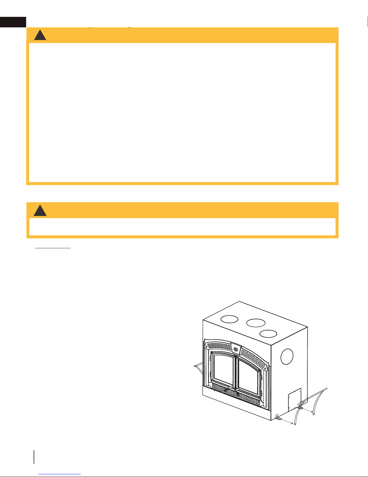
It is recommended that in all cases, the appliance be secured to the fl oor. Use the pallet packing brackets
to accomplish this.
W415-1761 / B / 12.21.18
3
Page 4

EN
table of contents
1.0 dimensions 5
2.0 general information 6
2.1 specifi cations 6
2.2 general instructions 6
2.3 rating plate information 7
2.4 high effi ciency heating 8
2.4.1 hot air gravity vent system (NZ220) 8
2.4.2 central heating system (NZ62CH) 9
2.4.3 blower circulation (NZ64) 9
3.0 installation planning 10
3.1 appliance placement 10
3.2 outside combustion air 11
3.3 fl oor protection 12
3.3.1 ember strip and hearth extensions 12
3.4 hearth examples 13
4.0 installation 14
4.1 chimney 14
4.2 typical chimney installation 15
4.3 adding chimney sections 16
4.4 offset chimney installation 17
4.5 installing fl ashing and storm collar 18
4.6 typical existing masonry 18
5.0 framing 19
5.1 clearance to combustibles 19
5.2 minimum enclosure clearances 20
5.3 minimum mantel clearances 20
6.0 finishing 21
6.1 ventilation openings 22
6.2 baffl e installation 23
6.3 faceplate installation 24
6.3.1 template removal 24
6.3.2 faceplate, hinge, ash lip and air
control arm installation 24
6.3.3 door installation 25
6.3.4 door gap adjustment 26
6.3.5 catalyst temperature monitor
installation 27
6.4 optional NZ64 blower installation 30
7.0 selecting wood 33
8.0 operation 34
8.1 appliance operation 34
8.2 bypass door 35
8.3 catalyst 36
8.4 operating sounds, smells and
characteristics 36
8.5 air control 36
8.6 fi re extinguishers / smoke and
carbon monoxide detectors 36
8.7 fuel loading and burn cycle 37
8.8 lighting a fi re 38
8.9 smoking 40
8.10 overnight burn 40
8.11 re-loading the appliance 40
9.0 maintenance 41
9.1 ash removal procedures 41
9.2 catalyst inspection and replacement
41
9.3 creosote formation and removal 44
9.4 run-away or chimney fi re 44
9.5 chimney cleaning 44
9.6 cast iron door glass and gasket
replacement 45
9.7 internal gasket replacement 46
9.8 care of glass 49
9.9 care of catalyst 49
9.10 care of plated parts 49
9.11 NZ64 blower replacement 50
10.0 replacement parts 51
10.1 overview 51
11.0 troubleshooting 53
11.1 general troubleshooting 53
11.2 catalyst troubleshooting 54
12.0 warranty 55
13.0 service history 57
note:
Changes, other than editorial, are denoted by a vertical line in the margin.
4
W415-1761 / B / 12.21.18
Page 5
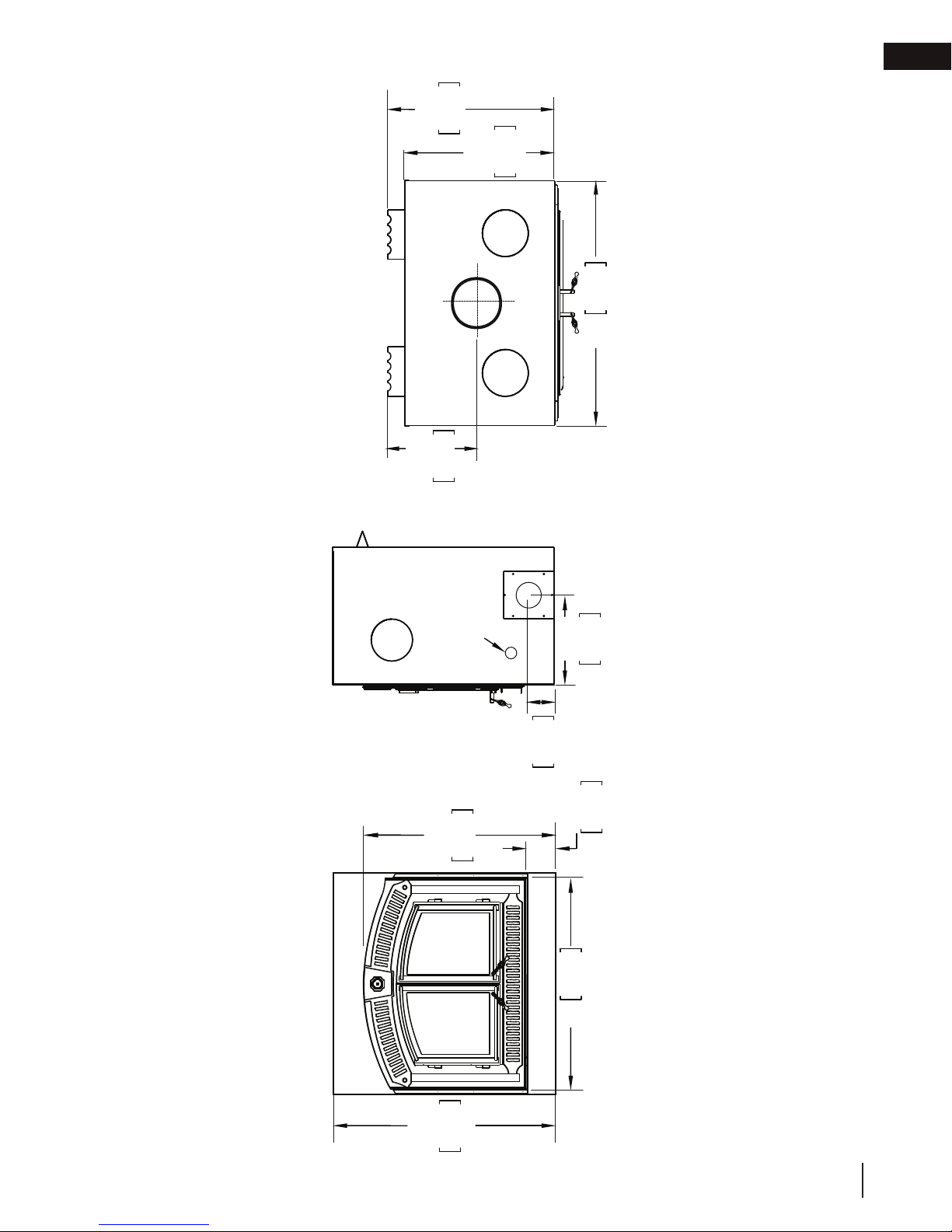
29 1/4"
743mm
395mm
15 9/16"
667mm
26 1/4"
1067mm
42"
1.0 dimensions
dimensions
EN
ELECTRICAL INLET
945mm
945mm
37 3/16"
37 3/16"
5"
127mm
17 1/8"
435mm
AIR INLET ON LEFT SIDE
5 1/2"
140mm
1016mm
40"
43 1/8"
1095mm
W415-1761 / B / 12.21.18
5
Page 6
EN
2.0 general information
general information
WARNING
!
• This appliance and its components are designed to be installed and operated as a system. Any alteration
to or substitution for items in this system, unless allowed by these installation instructions, will void the
Intertek listing and may void the product warranty. It may also create a hazardous installation. Read
through these instructions thoroughly before starting your installation and follow them carefully throughout
your project.
2.1 specifi cations
Width 42” (106.7cm)
Depth 29 1/4” (74.3cm)
Flue Center Line to Rear 15 9/16” (14.1cm)
Flue Center Line to Side 21” (53.3cm)
Height 43 1/8” (109.5cm)
Chamber (D.W.H.) 13.75” x 25.75” x x12.5” (349mm x 654mm x 318mm)
Capacity 2.377 Cubic Feet (0.08 Cubic Meter)
Approximate Area Heated* Up to 3,000 Square Feet (279 Square Meter)
Heat Output** 60,000 BTU (17.6 KW)
Duration Low Fire* 17 hrs
Weight 551 lbs (249.9kg)
Ideal Wood Length 25” (63.5cm)
Optional Blower 318 CFM
Combustion Air Inside or Outside
Electrical Draw < 12 Amps
Heat Output Range*** 9,200 to 23,400 BTU
* Figures will vary considerably with individual conditions.
** Wolf Steel Ltd. estimated realistic BTU/hr with hardwood logs and regular refueling.
*** Under specifi c test conditions conducted during EPA emission testing, this heater delivered heat at these
rates in the chart above. The heater operates at its best effi ciency when operated on high.
2.2 general instructions
WARNING
!
• Before installing this appliance, contact the local building or fi re authority and follow their guidelines.
• This appliance must be installed by a qualifi ed installer. Follow the installation directions. Do not operate
without fully assembling all components.
• If this appliance is not properly installed, a house fi re may result.
• Do not expose the appliance to the elements (ex. rain, etc.) and keep the appliance dry at all times. Wet
insulation will produce an odour when the appliance is used.
• This appliance is hot when operated and can cause severe burns if contacted. Children and pets must be
kept from touching the appliance when it is hot. Contact your local authorized dealer/distributor for safety
screens that may be available for this product.
• Combustible material such as fi rewood, wet clothing, etc. placed too close can catch fi re. Objects placed
in front of the appliance must be kept a minimum of 48” (121.9cm) from the front of the appliance.
• All wiring should be done by a qualifi ed electrician and shall be in compliance with local codes and with
the National Electric Code ANSI/NF No. 70-Current (in the United States), or with the current CSA C22.1
Canadian Electric Code (in Canada).
• This wood heater contains a catalytic combustor, which needs periodic inspection and replacement
for proper operation. It is against United States Federal regulations to operate this wood heater in a
manner inconsistent with operating instructions in this manual, or if the catalytic element is deactivated or
removed.
6
W415-1761 / B / 12.21.18
Page 7

general information
2.3 rating plate information
Rating plate is located behind the appliance faceplate, underneath the fi rebox.
This illustration is for reference only. Refer to the rating plate on the appliance for accurate information.
EN
U.S. Environmental Protection Agency
Certified to comply with 2015, particulate emissions standards:
Not approved for sale after May 15, 2020
EPA test method 28R, ASTM E2515 and ASTM E2780
Certified emission rate of 3.25g/h
MINIMUM CLEARANCES TO COMBUSTIBLES:
0"(0 mm)
REAR
SIDE
FLOOR
HEADER
CHIMNEY
MANTEL
TOP FACING
SIDE FACING
ADJACENT SIDEWALL
HEARTH PROTECTION
HEARTH PROTECTION
*TOP OF UNIT
(ENCLOSURE CEILING)
*FOR FURTHER INFORMATION SEE THE
MANUFACTURER'S INSTALLATION AND OPERATING
6"(153 m)
0"(0 mm)
84"(2.13 m)
2"(51 mm)
12"(305 mm)
84"(2.13 m)
6"(153 mm)
21"(534 mm)
21"(534 mm)
6"(153 mm)
84"(2.13 m)
MANUAL.
TO STAND-OFFS
FROM SIDE OF UNIT
FROM BASEOF UNIT
FROM BASE OF UNIT
REFER TO MANUFACTURER'S
INSTALLATION INSTRUCTIONS.
TO TOP EDGE OF FACEPLATE
FROM BASE OF UNIT
FROM SIDE OF UNIT
TO EDGE OF FACEPLATE
FROM FRONT OF UNIT
FROM SIDES OF UNIT
FROM BASE OF UNIT
84”
84” MINIMUM
ENCLOSURE HEIGHT
84”
WITH VENTILATED
ENCLOSURE. SEE
VENTILATION SIZE
REQUIREMENTS.
DÉGAGEMENTS MINIMAUX DE LA CHEMINÉE PRÉFABRIQUÉE
ARRIÈRE 0"(0 mm) AUX ESPACEURS
CÔTÉ 6”(153 mm) DU CÔTÉ DE L’APPAREIL
PLANCHER 0”(0 mm) DE LA BASE DE L‘APPAREIL
LINTEAU
CHEMINÉE 2"(51 mm) RÉFÉREZ-VOUS AU MANUEL
TABLETTE 12"(305 mm) DU HAUT DE LA FAÇADE
DESSUS 84"(2.13 m) DE LA BASE DE L'APPAREIL
CÔTÉ 6"(153 mm) DU CÔTÉ DE L'APPAREIL
MUR LATÉRAL ADJACENT 21"(534 mm) DU BORD DE LA FAÇADE
PROTECTION DE PLANCHER 21"(534 mm) DU DEVANT DU FOYER
PROTECTION DE PLANCHER 6"(203 mm) DES CÔTÉS DU FOYER
*
HAUT DE L'APPAREIL 84"(2.13 m) DE LA BASE DE L'APPAREIL
(PLAFOND DE L'ENCLAVE)
DO NOT REMOVE THIS LABEL
CERTIFIED TO / CERTIFIÉ SELON: ULC S610, UL-127
SERIAL
9700539 (WSL)
4001657 (NGZ)
4001658 (NAC)
4001659 (WUSA)
INSTALL AND USE ONLY IN ACCORDANCE WITH THE MANUFACTURER'S INSTALLATION AND OWNER'S MANUAL. THIS WOOD
HEATER NEEDS PERIODIC INSPECTION AND REPAIR FOR PROPER OPERATION. CONSULT THE OWNER’S MANUAL FOR
FURTHER INFORMATION. IT IS AGAINST UNITED STATES FEDERAL REGULATION TO OPERATE THE WOOD HEATERS IN A
MANNER INCONSISTENT WITH THE OPERATING INSTRUCTIONS. CONTACT LOCAL BUILDING OR FIRE OFFICIALS ABOUT
RESTRICTIONS AND INSTALLATION INSPECTION IN YOUR AREA. DO NOT CONNECT THIS UNIT TO A CHIMNEY SERVING
ANOTHER APPLIANCE.
POUR INSTALLATION ET UTILISATION CONFORMÉMENT AUX MANUEL D'INSTRUCTIONS DU FABRICANT. CET APPAREIL DE
CHAUFFAGE AU BOIS DOIT FAIRE L'OBJET D'UNE INSPECTION ET D'UN ENTRETIEN PÉRIODIQUES POUR UN
FONCTIONNEMENT ADÉQUAT. CONSULTEZ LE MANUEL D'INSTRUCTIONS POUR PLUS D'INFORMATION. OPÉRER DES
APPAREILS DE CHAUFFAGE AU BOIS D’UNE MANIÈRE NON CONFORME AUX INSTRUCTIONS DE FONCTIONNEMENT VA À
L'ENCONTRE DE LA RÉGLEMENTATION FÉDÉRALE DES ÉTATS-UNIS. RENSEIGNEZ-VOUS AUPRÈS DES AUTORITÉS
LOCALES DU BÂTIMENT OU DU SERVICE DES INCENDIES AU SUJET DES RESTRICTIONS ET DES INSPECTIONS
D'INSTALLATION DANS VOTRE RÉGION. NE PAS RACCORDER À LA CHEMINÉE D'UN AUTRE APPAREIL.
OPTIONAL COMPONENTS / PIECES OPTIONNELS
BLOWER KIT / SOUFFLERIE :
NZ64 / VENTILATION PAR GRAVITE / NZ220
ACCESSORIES PROVIDED BY MANUFACTURER ARE TO BE UTILIZED ONLY/ SEULS LES ACCESSOIRES FOURNIS PAR LE FABRICANT PEUVENT
ÊTRE UTILISÉS.
YEAR:
MONTH:
LISTED FACTORY BUILT FIREPLACE/FOYER PRÉFABRIQUÉ HOMOLOGUÉ
NZ64 / HOT AIR GRAVITY VENTS / NZ220
2016
MANUFACTURE DATE:
2017 2018
243658710912111
24 NAPOLEON ROAD. BARRIE, ONTRAIO L4M 0G8 CANADA
NZ3000H
NO.
MODEL NO. NZ3000H
N° DE MODÈLE NZ3000H
2019 2020
U.S. Environmental Protection Agency
Certifié conforme à la norme d’ émanation de particles de 2015
Non approuvé pour la vente après le 15 mai 2020
Méthode de test EPA 28R, ASTM E2515 et ASTM E2780
Taux d'émission de 3.25g/h certifié
STANDARD AUX MATÉRIAUX COMBUSTIBLES
84"(2.13 m) DE LA BASE DE L'APPAREIL
D'INSTRUCTIONS DU FABRICANT
*POUR PLUS D'INFORMATIONS, CONSULTEZ LE MANUEL
D'INSTRUCTIONS DU FABRICANT.
LA FAÇADE DOIT
ÊTRE COMPOSÉE
D’UN PANNEAU DE
CIMENT D’UNE
MINIMALE DE 84",
COMBUSTIBLE ET
UNE OSSATURE DE
BOIS PEUVENT
ÊTRE UTILISÉS À
PARTIR D’UNE
HAUTEUR DE 84"
AU-DESSUS DE LA
PANNEAU DE CIMENT SUR
NE RETIREZ PAS CETTE PLAQUE
COMPONENTS REQUIRED FOR INSTALLATION:
SHIPPED WITH THE FIREPLACE:
INSTALLATION MANUAL
BAFFLE
EMBER STRIP
SHIPPED WITH THE DOOR(S):
INSTALLATION INSTUCTIONS AND
HARDWARE
CHIMNEY REQUIREMENTS (see installation manual):
Chimney must be certified to one of the following standards ULC S604, ULC S610
or ULC S629 for Canada or UL 103HT or UL-127 for the United States
Masonry chimney installation: Stainless steel liner must be certified to ULC S640
M92 or ULC 639 for Canada or UL 1777 for the United States
MINIMUM CHIMNEY HEIGHT 15 ft (4.57 m) MAXIMUM NUMBER OF ELBOWS 4
MAXIMUM CHIMNEY HEIGHT 34 ft (10.36 m) CHIMNEY 7"ø
MAXIMUM OFFSET ANGLE 30º US - 45º CANADA
COMPOSANTS REQUIS POUR L'INSTALLATION:
LIVRÉ AVEC LE FOYER
MANUEL D'INSTRUCTIONS
DÉFLECTEUR
PARE-BRAISES
LIVRÉ AVEC LA/LES PORTE(S) :
INSTRUCTIONS D'INSTALLATION
ET QUINCAILLERIE
EXIGENCES POUR LA CHEMINÉE (voir le manuel d'instructions)
La cheminée doit être certifiée selon l'une des normes suivantes : ULC S610 ou ULC S629
pour le Canada ou selon les normes UL 103HT ou UL-127 pour les États-Unis
Installation dans une cheminée en maçonnerie : La gaine en acier inoxydable doit être
certifiée selon les normes ULC S640 M92 ou ULC 639 pour le Canada ou selon la norme
HAUTEUR MINIMALE DE LA CHEMINÉE 15 pi (4.57 m) NOMBRE MAXIMAL DE COUDES 4
HAUTEUR MAXIMALE DE LA CHEMINÉE 34 pi (10.36 m) LA CHEMINÉE 7"ø
ANGLE DE DÉVIATION MAXIMAL 30º US - 45º CANADA
• For use with cord wood only.
• Not for use in a Mobile Home
• Operate with feed doors
closed. Open to feed fire only.
• Transport ashes in an air-tight
non-combustible container.
UL 1777 pour les États-Unis
WARNING:
SHIPPED WITH FACEPLATE:
FACEPLATE
INSTALLATION INSTUCTIONS AND
HARDWARE
LIVRÉ AVEC LA FAÇADE:
FAÇADE
INSTRUCTIONS D'INSTALLATION ET
QUINCAILLERIE
AVERTISSEMENT :
• Tenir les portes fermées lorsque le foyer fonctionne.
N'ouvrez que pour ravitailler le feu.
• Transporter les cendres dans un contenant i
incombustible possédant un couvercle étanche.
• Pour emploi avec du bois de corde seulement.
• Ne peut être installé dans une maison mobile.
HAUTEUR
SELON LA
HAUTEUR DU
PLAFOND.
UNE FAÇADE
BASE DE
L’APPAREIL.
LE CÔTÉ DE L’APPAREIL
JUSQU’AUX MATÉRIAUX
COMBUSTIBLES.
HAUTEUR
MINIMALE DE 84”
POUR L’ENCEINTE
VENTILÉ.
RÉFÉREZ AUX
EXIGENCES DE LA
TAILLE DE
VENTILATION.
Les ouvertures de ventilation sont requises pour toutes les enceintes
allant jusqu’à 96" de hauteur. Elles sont recommandées pour toutes
les enceintes. Au-delà de 84", des matériaux de finition combustibles
peuvent être utilisés en façade.
PREVENT CREOSOTE FIRE: INSPECT
CHIMNEY AND CHIMNEY CONNECTOR, IF
APPLICABLE, TWICE MONTHLY AND CLEAN
IF NECESSARY.
DO NOT OVERFIRE: IF EXTERIOR OF UNIT
GLOWS RED, YOU ARE OVERFIRING.
KEEP FURNISHINGS AND OTHER
COMBUSTIBLE MATERIALS A
CONSIDERABLE DISTANCE AWAY FROM
APPLIANCE.
TYPE OF FUEL: CORD WOOD ONLY.
PRÉVENIR LES FEUX DE CRÉOSOTE:
INSPECTEZ LA CHEMINÉE OU LE RACCORD
DE CHEMINÉE, SI APPLICABLE, DEUX FOIS
PAR MOIS ET NETTOYEZ SI NÉCESSAIRE.
NE SURCHAUFFEZ PAS: SI L'EXTÉRIEUR DE
L’APPAREIL DEVIENT ROUGE, VOUS
SURCHAUFFEZ.
GARDEZ LES MEUBLES ET AUTRES
MATERIÉLS COMUSTIBLES À UNE
DISTANCE CONSIDERABLE DE L'APPAREIL
DE CHAUFFAGE.
TYPE DE COMBUSTIBLE: BOIS DE CORDE
SEULEMENT.
IMPORTANT
BEFORE COMMENCING INSTALLATION
REFER TO THE LABEL LOCATED BEHIND
THE FACEPLATE AND TO THE
MANUFACTURER'S INSTALLATION
INSTRUCTIONS PACKAGED TOGETHER
WITH THIS UNIT.
THE INSTALLATION MUST BE APPROVED
BY THE AUTHORITY HAVING
JURISDICTION.
AVANT DE COMMENCER L'INSTALLATION,
RÉFEREZ-VOUS À L'ÉTIQUETTE QUI SE
TROUVE DERRIÈRE LA FAÇADE AINSI
QU'AUX INSTRUCTIONS D'INSTALLATION
DU MANUFACTURIER FOURNIES AVEC
L’APPAREIL.).
L'INSTALLATION DOIT ÊTRE APPROUVÉE
PAR L'AUTORITÉ COMPÉTENTE.
Une ouverture de ventilation de 40
pouces carrés minimum est requise dans
le haut et le bas de l’enceinte.
W385-2128 / C
note:
The rating plate must remain with the appliance at all times. It must not be removed.
W415-1761 / B / 12.21.18
7
Page 8

EN
general information
2.4 high effi ciency heating
The NZ3000H is a high effi ciency appliance that may be operated as a standalone system, however, a blower is
recommended to further enhance the effi ciency of the appliance.
The NZ3000H and its optional heat distribution systems cannot be connected to other duct systems. The
NZ3000H must be ducted independently when these installation options are used.
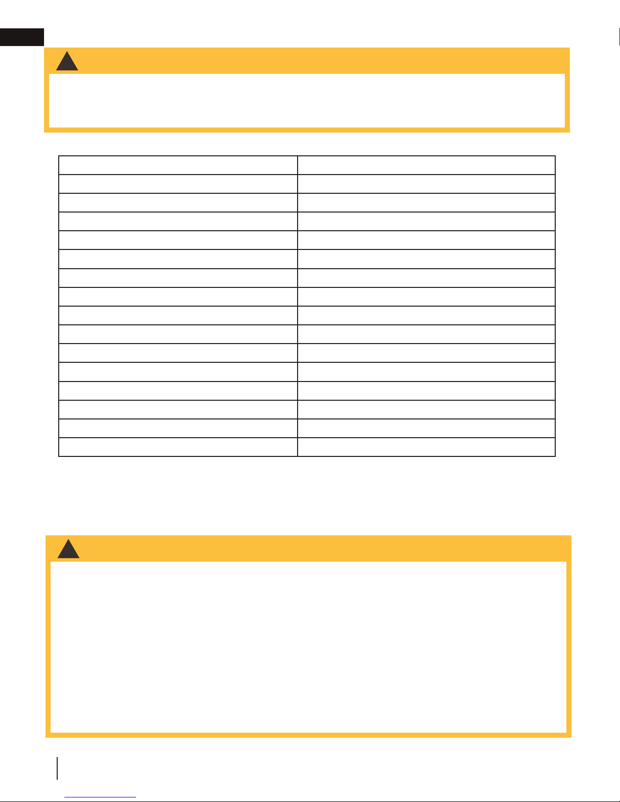
2.4.1 hot air gravity vent system (NZ220)
WARNING
!
• All hot air gravity vents must be insulated.
May be used to distribute heat
to an adjoining room (located
either above, or beside the room
containing the appliance) by way
of vents, eliminating the need of
an additional blower. While this
system may be used in conjunction
with the optional blowers, it could
reduce the fl ow of hot air being
distributed to additional rooms. It
must be experimented with and
the dampers adjusted manually to
suit your requirements. This may
take a few attempts; thereafter
adjustments should no longer be
required as is normally experienced
with your central heating system
registers. No more than two hot air
gravity vents can be installed to an
appliance. Individual vent runs are
not to exceed 10 feet (3m).
5 FT (1.5M)
MINIMUM
FROM FLOOR
GROUND FLOOR
12” (304.8MM)
MINIMUM PIPE
TO CEILING
5 FT (1.5M)
MINIMUM
FROM FLOOR
NO
DUCTING
When installed with a masonry chimney, the hot air gravity and central heating system can only be installed off the sides.
*
8
W415-1761 / B / 12.21.18
GRAVITY VENT
OPTION (1 DUCT)
OPTION (2 DUCTS)
GRAVITY VENT
GRAVITY VENT OPTION
SIDES
*
ONLY
CENTRAL HEATING &
GRAVITY VENT OPTION
Page 9
general information
2.4.2 central heating system (NZ62CH)
May be used to heat rooms up to 50 feet (15.2m) from the appliance. A wall mounted thermostat located in the
room to be heated controls the blower supplying warm air from the room containing the appliance. Consult with
a heating specialist to ensure a proper duct layout for your home. If the NZ62CH is installed at the bottom of the
appliance, it could introduce a cool draft into the room that the appliance is installed in. When attached to the top
sides of the appliance, it provides a higher heat output. This option may not be used in mobile homes.
EN
EXAMPLE OF DEDICATED DUCTING SYSTEM
NO
DUCTING
When installed with a masonry chimney, the hot air gravity and central heating system can only be installed off the sides.
*
CENTRAL HEATING
CENTRAL HEATING
SIDES
*
ONLY
CENTRAL HEATING &
GRAVITY VENT OPTION
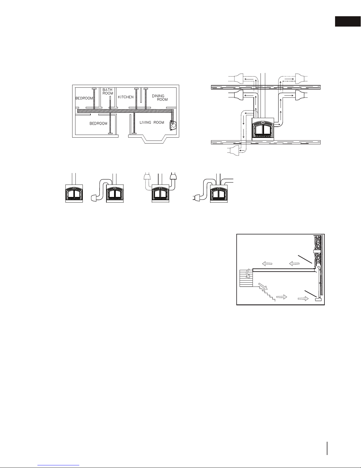
2.4.3 blower circulation (NZ64)
The NZ64 provides an ideal means of circulating warm air within the room it
resides.
BLOWER
LOCATION
OPTIONS
ATTI C
The blower will only operate when the doors are fully closed.
We recommend installing the blower in a different room or even a different
level of the house. This will generate greater air movement and improve the
distribution of the warm air cooling from the appliance as well as improving air
movement in the summer months if using the summer bypass switch option.
These options may be incorporated with one another. If the optional blower is
to be installed, make provision during framing to route a 110 volt power line to
the appliance. Detailed installation instructions are included with each venting
kit.
NZ3000 H
BLOWER
W415-1761 / B / 12.21.18
9
Page 10
EN
3.0 installation planning
installation planning
WARNING
!
• Wear gloves, protective footwear and safety glasses for protection.
• Carefully follow the instructions for assembly of the pipe and other parts needed to install the appliance.
Failure to do so may result in a fi re, especially if combustibles are too close to the appliance or chimney and air
spacers are blocked, preventing the free movement of cooling air.
• Do not draw outside air from garage spaces. Exhaust products of gasoline engines are hazardous. Do not
install outside air ducts such that the air may be drawn from attic spaces, basements or above the roofi ng
where other heating appliances or fans and chimneys exhaust or utilize air. These precautions will reduce the
possibility of appliance smoking or air fl ow reversal. The outside air inlet must remain clear of leaves, debris, ice
and/or snow. It must be unrestricted while appliance is in use to prevent room air starvation which can cause
smoke spillage and an inability to maintain a fi re. Smoke spillage can also set off smoke alarms.
• Negative pressure within your home may inadvertently affect your appliance.
• To prevent contact with sagging or loose insulation, the appliance must not be installed against vapour barriers
or exposed insulation. Localized overheating could occur and a fi re could result.
• Do not use makeshift compromises during installation. Do not block or restrict air, grille or louvre openings. Do
not add a hood.
• To prevent personal injury, keep hand tools in good condition, sharpen cutting edges and make sure tool
handles are secure.
• Always maintain the minimum air space required in the enclosure to prevent fi res.
• Check with local building offi cials for any permits required for installation of this appliance and notify your
insurance company prior to proceeding.
3.1 appliance placement
WARNING
!
• Do not install into any area having a height less than 7 feet (2.1m) (ceiling of enclosure to appliance
bottom, excluding hearth height).
IMPORTANT
This appliance, fully dressed, weighs 551 lbs. (249.9kg). Ensure there is adequate fl oor support for the appliance,
chimney and facing material. Some material could weigh thousands of pounds.
We recommend that the appliance be secured to the fl oor in all cases.
Remove and discard the lifting handles. Bend the tabs down and secure the appliance to the fl oor.
The location of windows, doors and the traffi c
fl ow in the room where the appliance is to be
located should be considered. If possible, you
should choose a location where the chimney
will pass through the house without cutting a
fl oor or roof joist.
10
W415-1761 / B / 12.21.18
Page 11
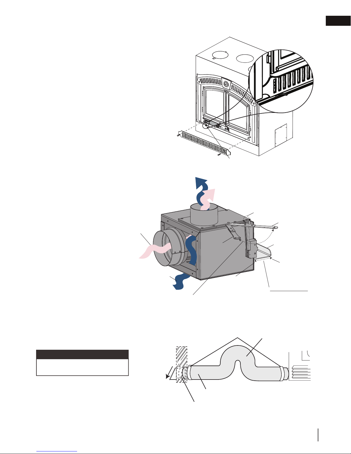
3.2 outside combustion air
Model NZ3000H has the option of taking outside air
directly into the appliance through the opening on the
left hand side or taking inside air through the lower front
grille or a combination of both. For inside air, push in the
control slider.
If the optional outside air kit (available through your
authorized dealer) is installed, it must not draw air from
the attic or garage. For outside air, pull out the air control
slider. It may only come from outside the house. The
maximum length of the 4” (101.6mm) air duct is 20
feet (6m); for greater lengths, enlarge the duct to a 6”
(152.4mm) diameter.
Decide on the most convenient location for the outside
air inlet duct and hood which may be installed above or
below fl oor level but must be installed above grade level.
Make a 5” (127mm) hole in an outside wall of the house.
From outside, place the outside air hood into the hole,
open side down.
installation planning
ADJUSTABLE COMBUSTION
AIR CONTROL LEVER
EN
At each end, carefully pull back the insulation sleeve
exposing the fl exible duct. Apply sealant to both the
outside air hood collar and the
connector collar at the appliance.
Place the insulated fl exible duct
over the outside air hood and over
the appliance outside air connector.
OUTSIDE
AIR
Carefully push the insulation sleeve
back over the duct.
Using the clamps, fasten the insulated
duct into place on both sides.
Cold air fl ow can be minimized by
INSIDE AIR
putting a dip or loop in the duct
creating a cold air trap. This trap can
also help prevent heat build-up and
exhausting out the intake due to stack
effect. The outside air kit inlet should
be positioned in a manner that will not
ADJUSTABLE COMBUSTION AIR
CONTROL LEVER
When this control is in it’s lowest setting
the micro switch shuts off the blower.
allow snow, leaves, etc. to block the
inlet. In some installations, the air duct
may need to be run vertically.
note:
OPEN
POSITION
INSIDE AIR
(PUSHED IN)
CLAMPS
MICRO
SWITCH
CLOSED
POSITION
INSIDE / OUTSIDE
AIR CONTROL
SLIDER
OUTSIDE AIR
(PULLED OUT)
PARTIALLY OPEN
COMBINATION
OF BOTH
COLD AIR
TRAP
Appliance must be set for inside air
if outside air is not connected.
INSULATION SLEEVE
FLEXIBLE DUCT
W415-1761 / B / 12.21.18
11
Page 12
EN
installation planning
3.3 fl oor protection
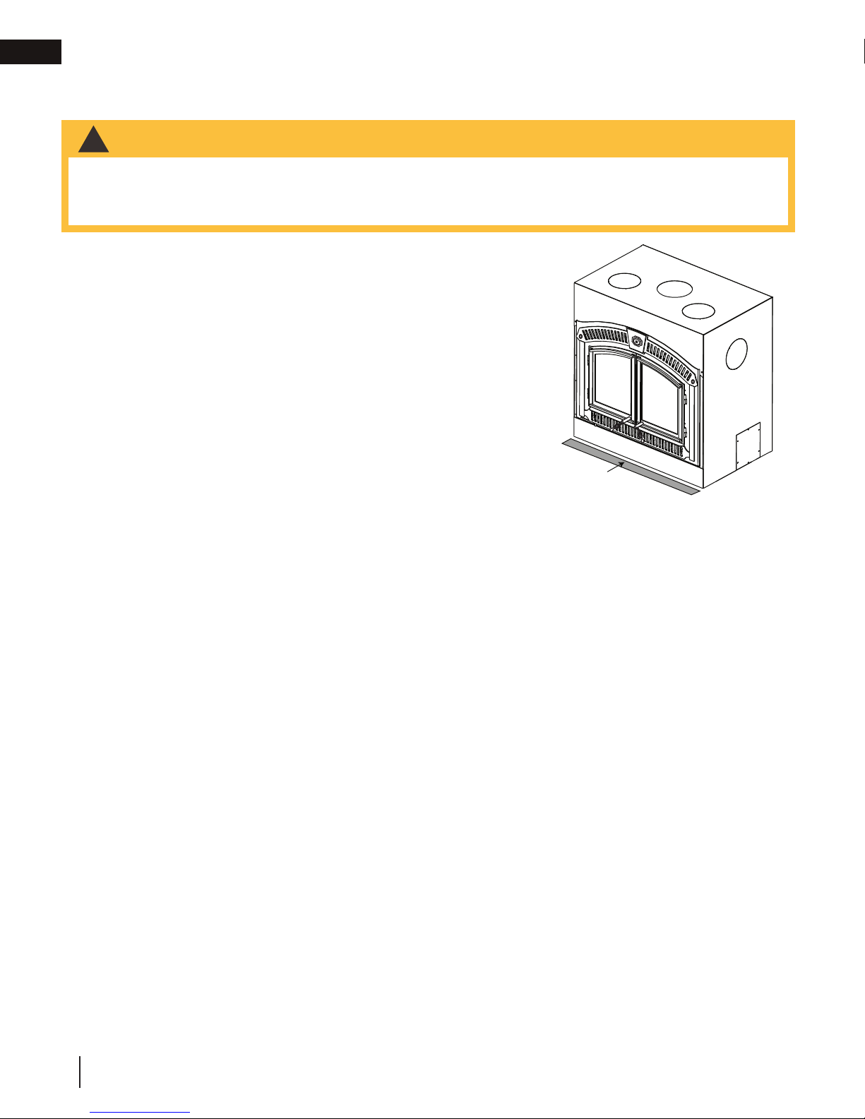
3.3.1 ember strip and hearth extensions
WARNING
!
• Hearth extensions are to be installed only as described to prevent high temperatures from occurring on
concealed combustible materials. Hearth ember strips prevent burning or hot particles from inadvertently
falling directly on combustible surfaces in the event the building should settle and disturb the original
construction.
An acceptable 54” (137.2cm) x 20” (50.8cm) non-combustible (ie:
brick, stone or ceramic tile) hearth extension must be installed.
The hearth must extend a minimum 20" (50.8cm) in front of the
appliance.
The hearth must extend a minimum of 6" (152.4mm) to both sides of
the appliance.
The hearth must be constructed of a minimum of 1" (25mm) thick cement
board (or equivalent) plus ¼" (6.4mm) ceramic tile.
Ensure that the gap between the appliance and a non-combustible
hearth extension is sealed with sand/cement grout or covered with an
ember strip (or both) to prevent sparks and embers from falling into
this area.
Raised hearths must be constructed of non-combustible materials
such as cement blocks or bricks.
EMBER STRIP
(See “HEARTH
EXAMPLES” Section)
While the appliance can be installed directly on the fl oor (using the ember strip), a non-combustible hearth
extension is required in front of the appliance, that must not be built higher than the bottom of the appliance
faceplate. It may therefore be advisable to build the appliance on a raised platform.
A raised hearth together with the appliance built on a raised platform is recommended for easier wood loading and fi re
viewing.
12
W415-1761 / B / 12.21.18
Page 13
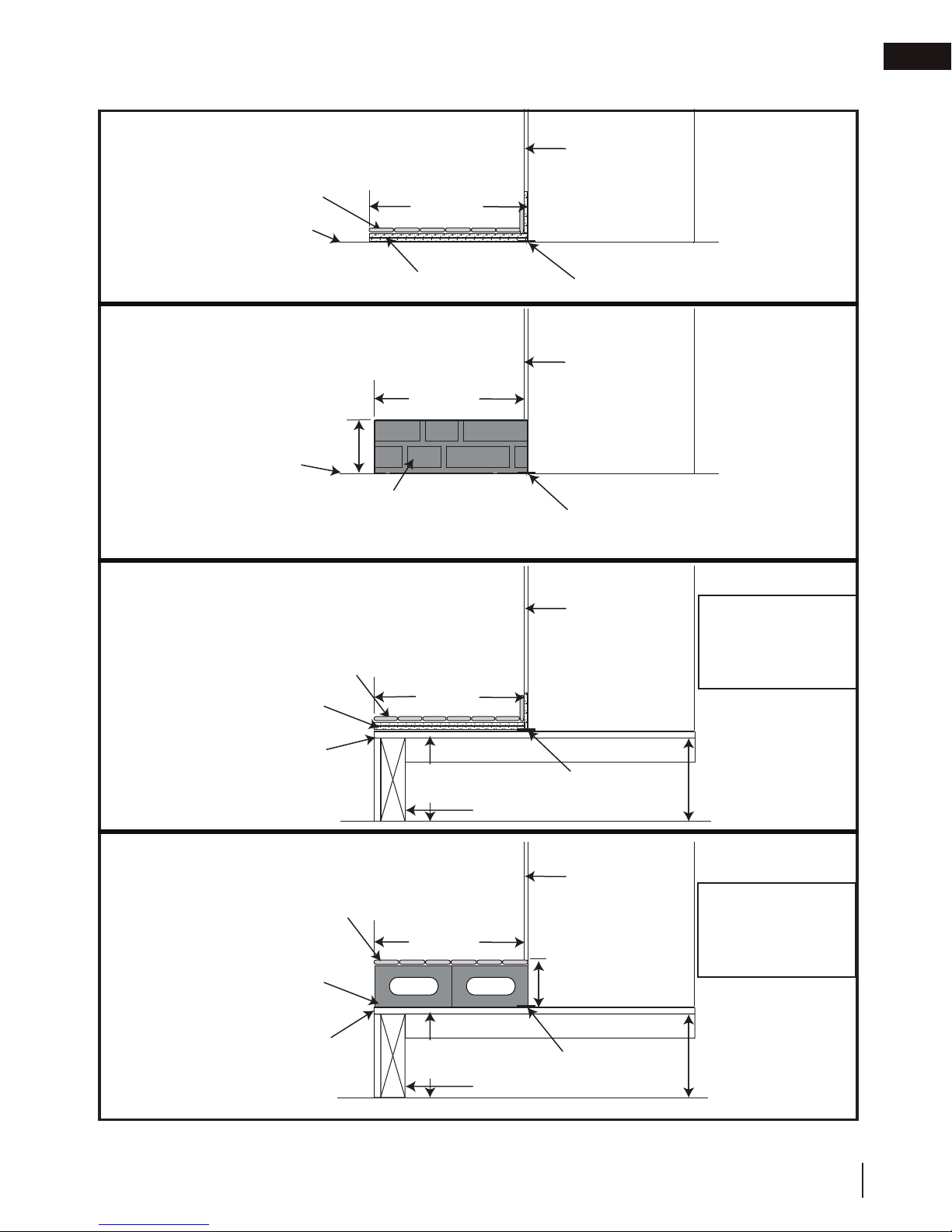
3.4 hearth examples
installation planning
EN
FLUSH HEARTH
MIN. 1/4” (6.4mm)
TILE OR MARBLE
COMBUSTIBLE FLOOR
RAISED HEARTH
COMBUSTIBLE FLOOR
RAISED APPLIANCE
MIN. 1/4” (6.4mm)
TILE OR MARBLE
MIN. 1” (25mm)
CEMENT BOARD
20” MIN.
(50.8cm)
MIN. 1” (25mm) CEMENT BOARD
20” MIN.
(50.8cm)
4
15
/
”
16
(125mm)
NON-COMBUSTIBLE MATERIALS
SUCH AS CEMENT
BLOCKS OR BRICKS
20” MIN.
(50.8cm)
FACEPLATE
EMBER STRIP
FACEPLATE
EMBER STRIP
FACEPLATE
WARNING: Ensure
raised platform is
designed to support load
of fully loaded appliance.
PLYWOOD
RAISED HEARTH AND APPLIANCE
MIN. 1/4” (6.4mm)
MARBLE OR STONE
NON-COMBUSTIBLE
MATERIALS SUCH
AS CEMENT BLOCKS
OR BRICKS
PLYWOOD
RAISED
APPLIANCE
COMBUSTIBLE FRAMING
20” MIN.
(50.8cm)
RAISED
APPLIANCE
COMBUSTIBLE FRAMING
EMBER STRIP
FACEPLATE
15
RAISED
HEARTH
4
(125mm)
EMBER STRIP
INCREASE
HEADER HEIGHT
THIS DIMENSION
See “Framing” section
WARNING: Ensure
raised platform is
designed to support load
/
16
of fully loaded appliance.
”
INCREASE
HEADER HEIGHT
THIS DIMENSION
See “Framing” section
W415-1761 / B / 12.21.18
13
Page 14
EN
4.0 installation
installation
WARNING
!
• Never install a single wall slip section or smoke pipe in a chase structure. The higher temperature of this
single wall pipe may radiate suffi cient heat to combustible chase materials to cause a fi re.
• To avoid danger of fi re, all instructions must be strictly followed, including the provision of air space
clearance between chimney system and enclosure. To protect against the effects of corrosion on those
parts exposed to the weather, we recommend that the chase top be painted with a rust-resistant paint.
• Maintain a minimum 2” (51mm) air clearance to all parts of the chimney system at all times. Failure to
maintain this 2” (51mm) air clearance will cause a structure fi re.
• Detailed instructions for installation of the chase top, storm collar and termination cap are packaged with
these parts.
• Firestop spacers must be used whenever the chimney penetrates a ceiling/fl oor area.
• The chimney must be sound and free of cracks. Clean your chimney a minimum of twice a year and as
required.
• Always seal penetrations with temperature rated sealing products.
4.1 chimney
note:
All venting connections must be in compliance with the chimney manufacturer’s installation instructions.
This appliance was tested to CAN/ULC S610 and UL 127 Factory Built Fireplace Standards. This appliance has
met the test criteria for Zero Clearance Installation to Combustible Surfaces and certifi ed to burn fi rewood only.
Any 7” (177.8mm) diameter chimney listed to these standards may be installed. In accordance with these
standards, the appliance may also be connected to any chimney listed to CAN/ULC-S604 and CAN/ULC-S629
for Canada or UL-103HT for the United States.
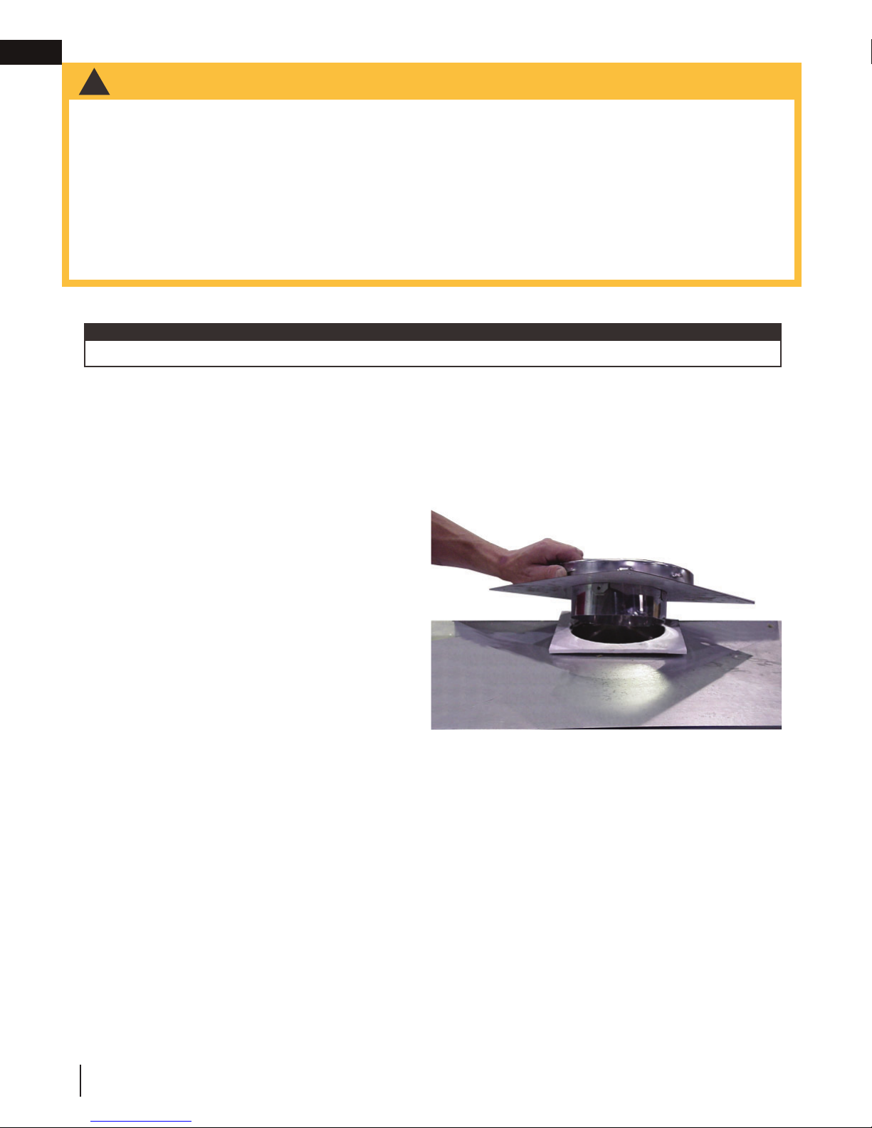
Installation of all types of factory-built chimney systems is to be in accordance with the chimney manufacturer’s
installation instructions. An appropriate chimney manufacturer’s anchor base plate is required in order to initiate
their system. An anchor base plate gasket is supplied
that suits a 7” (177.8mm) chimney. Use the high
temperature gasket (supplied) to seal between the
anchor plate and the appliance top.
For complete installation instructions, refer to
instructions provided with the manufactured chimney
system.
A chimney venting the appliance shall not vent any
other appliance. The minimum overall chimney height
from the top of the appliance is 15ft (4.6m). The
maximum overall chimney height from the top of the
appliance is 34ft (10.4m).
Factory-built chimney systems for use in dwellings
constructed for three or more families must be enclosed above the room in which the appliance is located. This
enclosure must have a fi re resistance rating equal to or greater than that of the fl oor or roof assembly through
which they pass.
The chimney should not be built with an offset angle in excess of 45° in Canada and 30° in USA. Ensure that
minimum clearances are maintained.
Portions of the chimney that extend through accessible spaces must always be encased to avoid personal
contact with the chimney and thereby avoid damage to the chimney.
The chimney must be supported at a maximum of 20ft (6.1m) intervals. Every 20 ft (6.1m) of chimney can weigh
up to approximately 200lbs (90.7kg). Refer to chimney manufacturer’s specifi cations.
ANCHOR PLATE FOR A FACTORY
ANCHOR PLATE
ANCHOR PLATE GASKET
APPLIANCE TOP
14
W415-1761 / B / 12.21.18
Page 15
4.2 typical chimney installation
installation
EN
STORM COLLAR
ROOF FLASHING
ATTIC INSULATION
SHIELD
RAIN CAP
(4.6m)
MINIMUM
(10.4m)
MAXIMUM
15 FT
34 FT
STORM COLLAR
ROOF FLASHING
ATTIC INSULATION
SHIELD
OFFSET
SUPPORT
RAIN CAP
MINIMUM
(10.4m)
MAXIMUM
FIRESTOP
12” (30.5cm)
15 FT
(4.6m)
34 FT
STORM COLLAR
ROOF FLASHING
ATTIC INSULATION
SHIELD
CEILING RADIATION
MIN*
RAIN CAP
SHIELD
OFFSET
SUPPORT
FIRESTOP
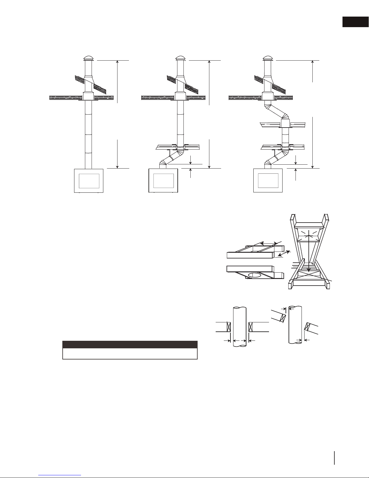
STRAIGHT CHIMNEY SINGLE OFF-SET CHIMNEY DOUBLE OFF-SET CHIMNEY
* The first flue offset closest to the top of the appliance must be a
minimum distance of 12” (30.5cm) from the top of the appliance.
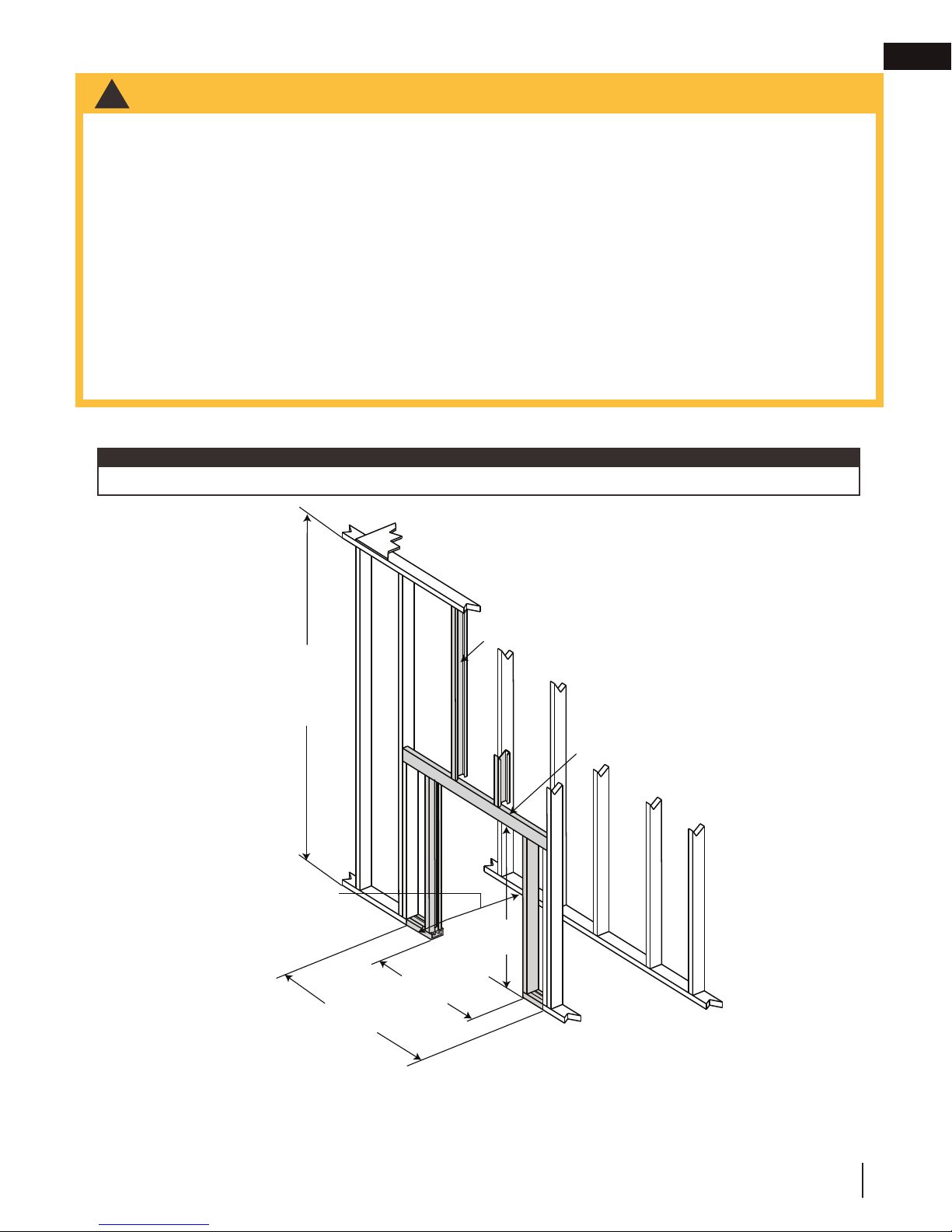
A. Move the appliance into position. Try to center the exhaust
flue of the appliance, midpoint between two joists to prevent
having to cut them. Use a plumb bob to line up the centre.
B. Cut and frame an opening in the ceiling to provide a
HEADERS
minimum clearance of 2” (50.8mm) between the outside of
the chimney and any combustible material. DO NOT FILL
THIS SPACE WITH ANY TYPE OF MATERIAL! Nail headers
between the joists for extra support. Firestop spacers must
be placed on each framed opening in any floor or ceiling
that the chimney passes through.
FIRESTOP SPACER UNDERSIDE OF JOIST
2" (50.8mm)
Min.
C. Hold a plumb bob from the underside of the roof to
determine where the opening in the roof should be.
Cut and frame the roof opening maintaining proper
2” (50.8mm) clearances.
note:
30° or 45° offsets may be installed back to back.
2" (50.8mm)
Min.
2" (50.8mm)
Min.
Typical Roof Joist FramingTypical Joist Framing
15 FT
(4.6m)
MINIMUM
34 FT
(10.4m)
MAXIMUM
12” (30.5cm)
MIN*
2" (50.8mm)
Min.
W415-1761 / B / 12.21.18
15
Page 16
EN
installation
4.3 adding chimney sections
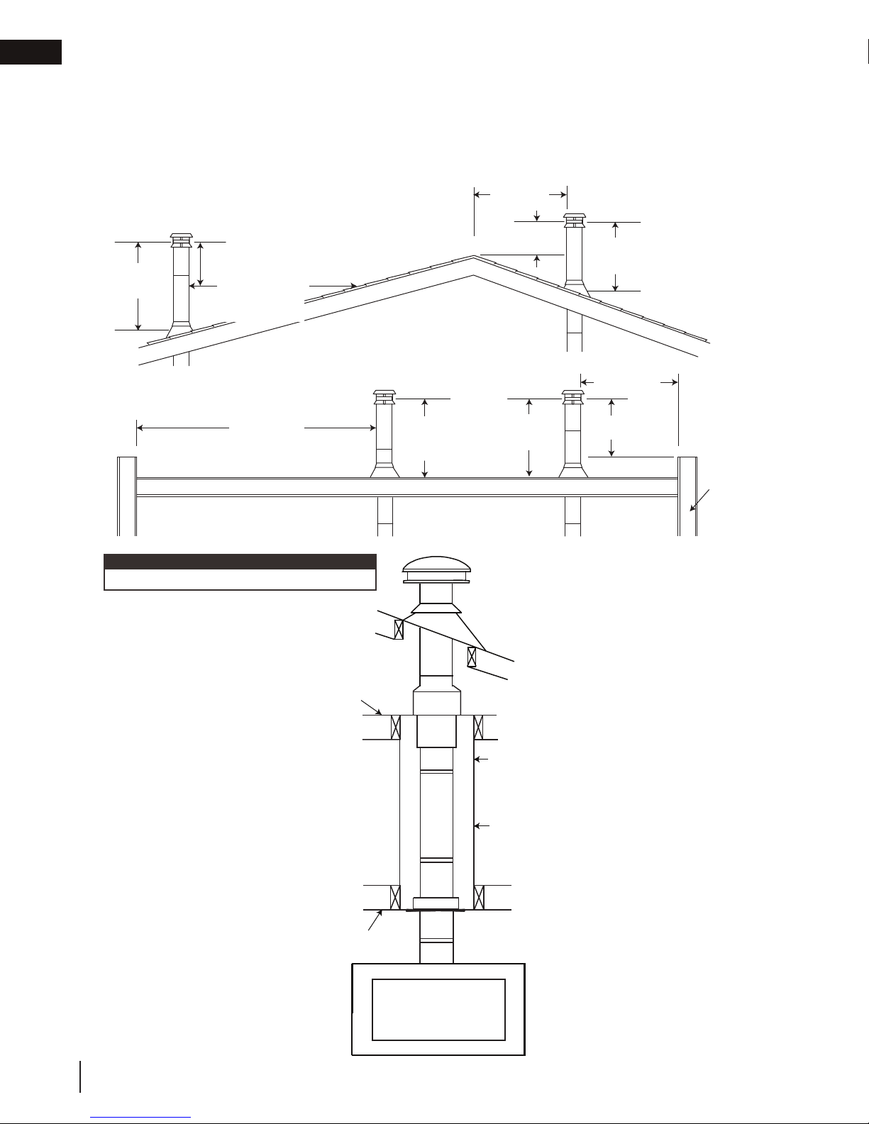
Add chimney sections, according to the manufacturer’s installation instructions. If the chimney system passes
through an attic space, a rafter radiation shield or attic insulation shield is required. The chimney must extend at
least 3ft (0.9m) above its point of contact with the roof and at least 2ft (0.6m) higher than any wall, roof or building
within 10ft (3.1m). If the chimney extends more than 5ft (1.5m) above the roof, it must be secured using a roof
brace or guide wires. A raincap must be installed to avoid internal damage and corrosion.
3 FT (1m)
MIN
2 FT (0.6m) MIN
10 FT (3m)
TO NEAREST
ROOFLINE
RIDGE
LESS THAN
10FT (3m)
2 FT (0.6m)
MIN
3 FT (1m)
MIN
LESS THAN
10FT (3m)
10 FT (3m)
OR MORE
FLAT ROOF
note:
This illustration is for wood appliances only.
Ceiling Joist
LIVING SPACE
Chimney must be
totally enclosed
when passing
through living space
with a minimum 2”
(51mm) clearance
to combustibles.
3 FT (1m)
MIN
3 FT (1m)
MIN
ATTIC SPACE
Chimney Lengths
Framed
Enclosure
2” (51mm)
clearance from
chimney to
combustible wall
2 FT (0.6m)
MIN
WALL
16
W415-1761 / B / 12.21.18
Floor, Ceiling Joist
Page 17

installation
4.4 offset chimney installation
WARNING
!
• Chimney sections installed between an offset and return require structural support to reduce off-center
loading and to prevent chimney sections from separating at the chimney joists.
• The chimney should not be built with an offset angle in excess of 45° in Canada and 30° in USA. Do not
combine offset chimney components to exceed these angles.
EN
The first flue offset closest to the top of the
appliance must be a minimum distance of
12" (30.5cm) from the top of the appliance.
Attach an elbow to the chimney section, angled
toward the offset. Secure according to chimney
manufacturer’s instructions. Chimney sections must
be adequately secured one to the other to ensure
they do not separate. To achieve the minimum
offset, attach and secure a second elbow. To
achieve longer offsets, you may install any available
length of chimney pipe between the elbows.
Supports must be used on the first vertical chimney
section after a return elbow.
Storm Collar
Roof Joist
Chimney Section
Elbow Support
Straps
Elbow
Rain Cap
Roof
Flashing
Attic Insulation
Shield
Elbow Support
Band
Elbow
Floor , Ceiling Joist
Firestop
If the offset length is more than 36” (91.4cm), an
intermediate support must be employed. To
achieve longer offsets, you may install any
available length of chimney pipe between the
elbows.The intermediate support must be used
in conjunction with an offset support.
W415-1761 / B / 12.21.18
17
Page 18
EN
installation
4.5 installing fl ashing and storm collar
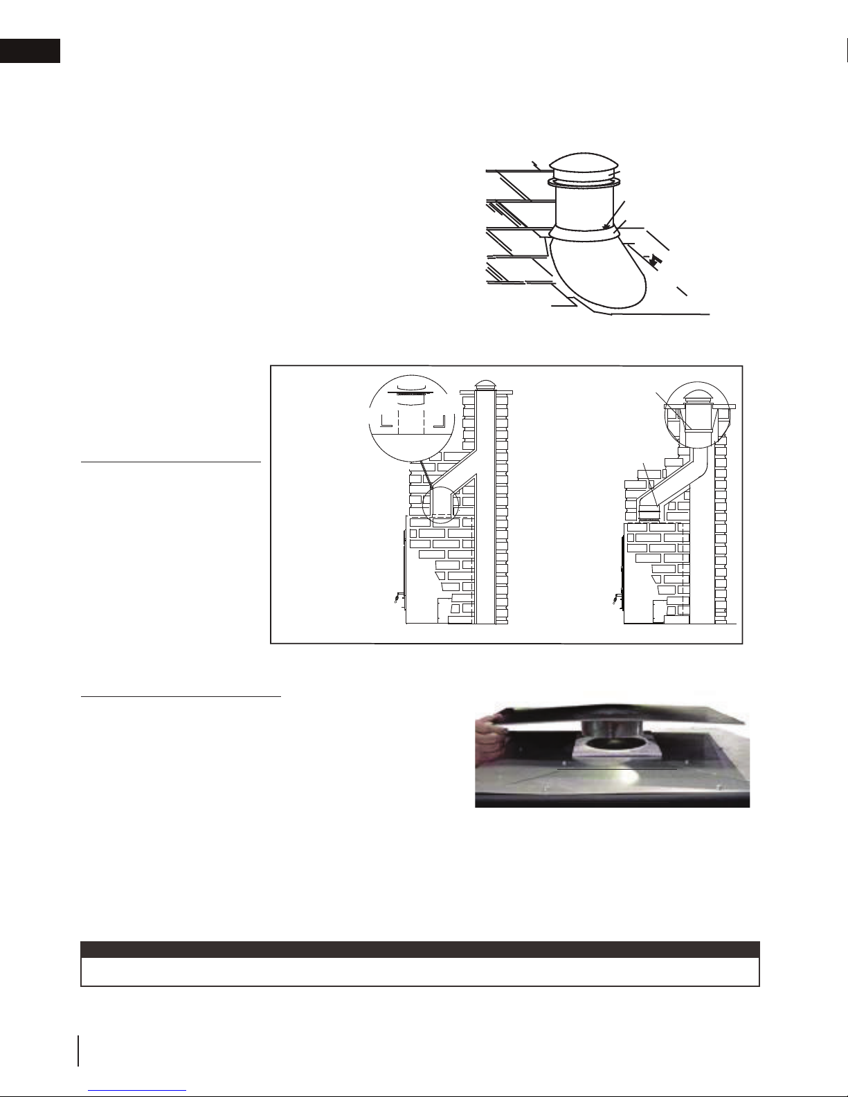
The following are generic installation instructions for installing the flashing around a chimney. Installation of all
types of factory-built chimney systems is to be in accordance with the chimney manufacturer’s installation
instructions. Remove the nails from the shingles above and to the sides of the chimney. Place the flashing over
the chimney pipe and slide underneath the sides and upper edge
of the shingles. Ensure that the chimney pipe is properly
centered within the flashing, giving a 3/4” (19.1mm) margin all
around. Fasten to the roof on the top and sides. DO NOT NAIL
through the lower portion of the flashing. Make weather-tight by
sealing with caulking. Where possible, cover the sides and top
edges of the flashing with roofing material. Apply waterproof
caulking, provided with the flashing, around the chimney, 1”
(25.4mm) above the top of the flashing and push the storm collar
down into the caulking. Insert a rain cap onto the top of the last
chimney section.
4.6 typical existing masonry
RAIN CAP
CAULKING
STORM COLLAR
WEATHER
SEALANT
FLASHING
The appliance may be
connected to either a lined or
unlined masonry chimney.
IF THE CHIMNEY IS LINED:
The fl ues must be made of
vitrifi ed clay and be in sizes
of 8” (203.2mm) square or
8” (203.2mm) round (inside
HI-TEMP GASKET
ANGLE IRON TO SUPPORT
CHIMNEY WEIGHT
APPLIANCE TOP
ANGLE IRON RESTS
ON BRICK SIDE-WALLS,
FREE OF UNIT.
FLUE TILE
FLUE TILE
SUPPORT
USE AN 7” (177.8mm)
OR 8" (203.2mm) LINER
WITH A DRIPLESS TYPE
A CONNECTOR
(IF USING 7” (177.8mm)
A 7” TO 8” INCREASER
FROM LINER TO FLUE
ALSO CAN BE USED.)
LINER
SUPPORT
diameters) or 8” x 12”
(203.2mm x 304.8mm) with
a minimum height of 15 feet
(4.6m) above the appliance.
8” (203.2mm) round fl ues are
recommended.
LINED CHIMNEY INSTALL
UNLINED CHIMNEY INSTALL
Installation must conform to
both national and local code requirements.
IF THE CHIMNEY IS UNLINED:
A stainless steel liner listed to either standard ULC-S640M in
Canada or UL-1777 in the USA, must be used: Liners for New
Masonry Chimneys, may be used to connect the appliance to the
chimney. The liner must be continuous from the appliance to the
HI-TEMP GASKET
chimney cap and be installed only per manufacturer’s instructions.
In both cases, the chimney structure must be supported by angle
iron anchored into the masonry walls. The allowance masonry
used in chimney construction is 3 1/2” (88.9mm) brick, solidly
mortared and must fully encase the fl ue. Ensure there are no
leaks.
FOR A MASONRY FIREPLACE USE A
PRE-FABRICATED CHIMNEY USE AN
FIREPLACE TOP
FLUE TILE SUPPORT. FOR A
ANCHOR PLATE.
In no case is the masonry enclosure to be supported by the
appliance. Allow a 1” (25.4mm) air cavity for expansion. Use the fl ue tile support accessory, see your local
authorized dealer / distributor.
note:
The fl ue tile support is to be suspended on appropriate levels.
18
W415-1761 / B / 12.21.18
Page 19
framing
WARNING
!
5.0 framing
• In order to avoid the possibility of exposed insulation or vapour barrier coming in contact with the appliance
body, it is recommended that the walls of the appliance enclosure be “fi nished” (i.e.: drywall/sheetrock), as
you would fi nish any other visible wall of a home. This will ensure that clearance to combustibles is maintained
within the cavity.
• A minimum of 6” (152mm) to combustible materials is required to both sides of the appliance, see “minimum
clearance to combustibles” section.
• When constructing the enclosure, allow for fi nishing material thickness to maintain clearances. Framing or
fi nishing material closer than the minimums listed must be constructed entirely of non-combustible materials.
Materials consisting entirely of steel, iron, brick, tile, concrete, slate, glass or plasters, or any combination
thereof are suitable. Materials that are reported as passing ASTM E 136, Standard Test Method for behaviour
of materials in a vertical tube furnace at 750ºC (1382ºF) and UL763 shall be considered non-combustible
materials.
• Do not build shelves or cupboards into the area above the appliance.
• Objects placed in front of the appliance must be kept a minimum of 48” (121.9cm) away from the front face of
the appliance.
• Prior to framing, refer to “catalyst temperature monitor installation” section.
5.1 clearance to combustibles
note:
Use metal studs wherever non-combustible facing is required.
EN
84” (213.4cm)*
MINIMUM
ENCLOSURE
+(,*+7ڟ
1
2
29
/
(74.9cm)**
(137.2cm)**
”
54”
1
2
42
/
”
(108cm)
STEEL STUD
44”
43 3/8”
(1118MM)*
(110.2cm)*
STEEL HEADER
* Allow for fi nished fl oor and hearth thickness when setting these dimensions.
** When constructing the enclosure allow for fi nishing material thickness to maintain clearances.
† See ventilation requirements for minimum height.
W415-1761 / B / 12.21.18
19
Page 20
EN
framing
5.2 minimum enclosure clearances
1
2
29
/
”
(749MM)
6” (152MM)
MIN
6” (152MM)
MIN
42” (1067MM)
42” (1067MM)
54” (1372MM)
6” (152MM)
MIN
29
(749MM)
6”
(152MM)
MIN
5
75
/16”
(1913MM)
”
2
1
42” (1067MM)
1
2
/
”
/
106
54” (1372MM)
(2553MM)
A minimum of 6” (62mm) is required to combustibles
from the side of the appliance.
note:
When constructing the enclosure, allow for fi nishing material thickness to maintain clearances.
5.3 minimum mantel clearances
WARNING
!
• Risk of fi re. Maintain all specifi ed air space clearances to combustibles. Failure to comply with these instructions
may cause a fi re or cause the appliance to overheat. Ensure all clearances (i.e. back, side, top, vent, mantel,
front, etc.) are clearly maintained.
• When using paint or lacquer to fi nish the mantel, the paint or lacquer must be heat resistant to prevent
discolouration.
• Facing, mantel and/or fi nishing materials must not interfere with air fl ow through air openings, louvres, operation
of louvres or doors or access for service.
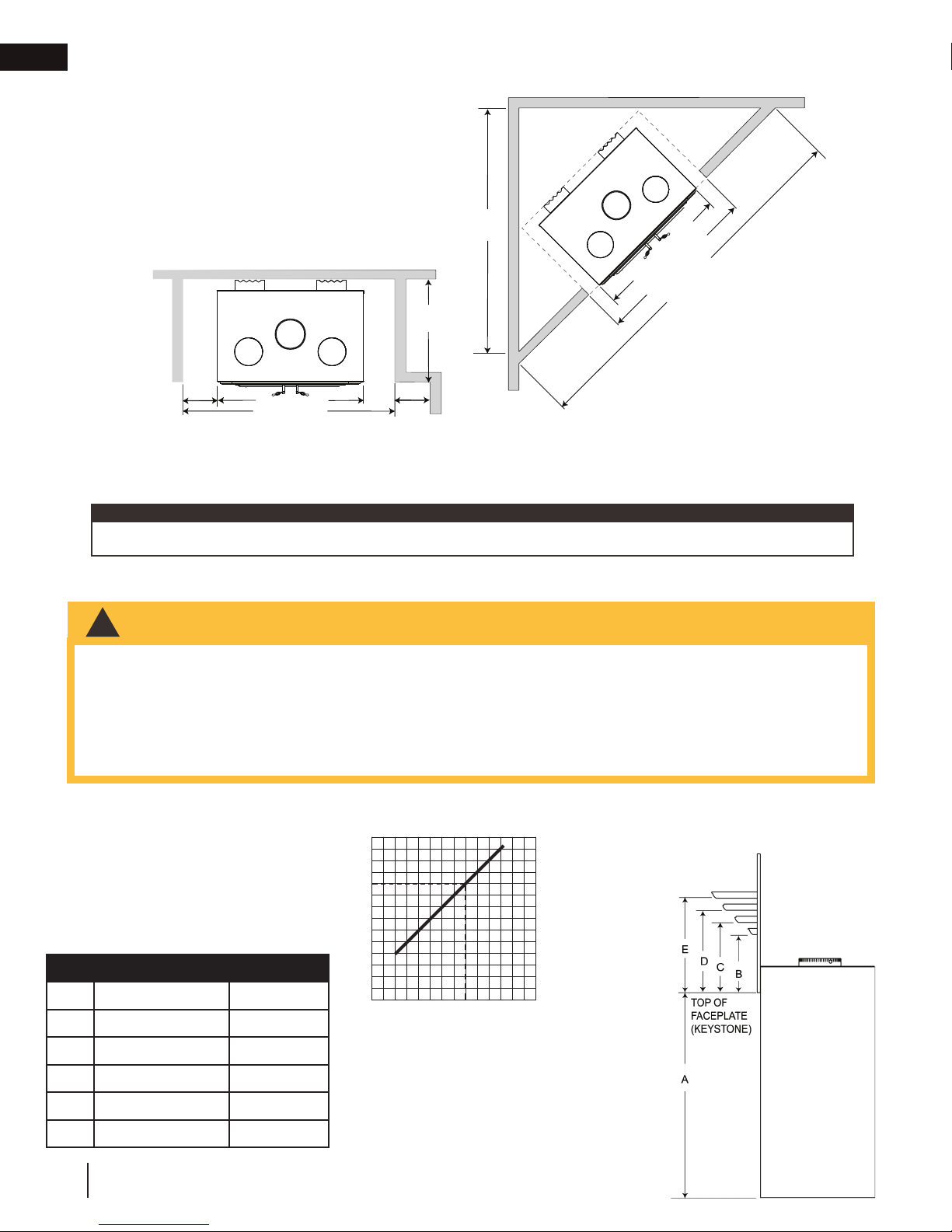
An optional combustible mantel must be a minimum of 12” (30.5cm) above the top of the faceplate and not to
extend more than 2” (51mm) from the surface. See chart below for further information.
MANTEL
HEIGHT
MANTEL DIMENSIONS
Ref. Height Depth
37 3/16” (945mm)
A
B
C
D
E
20
12” (305mm)
14” (356mm)
16” (406mm)
18” (457mm)
W415-1761 / B / 12.21.18
2” (51mm)
4” (102mm)
6” (152mm)
8” (203mm)
20
18
16
14
12
10
0
0
2
MANTEL WIDTH
468 01
12
Page 21

fi nishing
WARNING
!
6.0 fi nishing
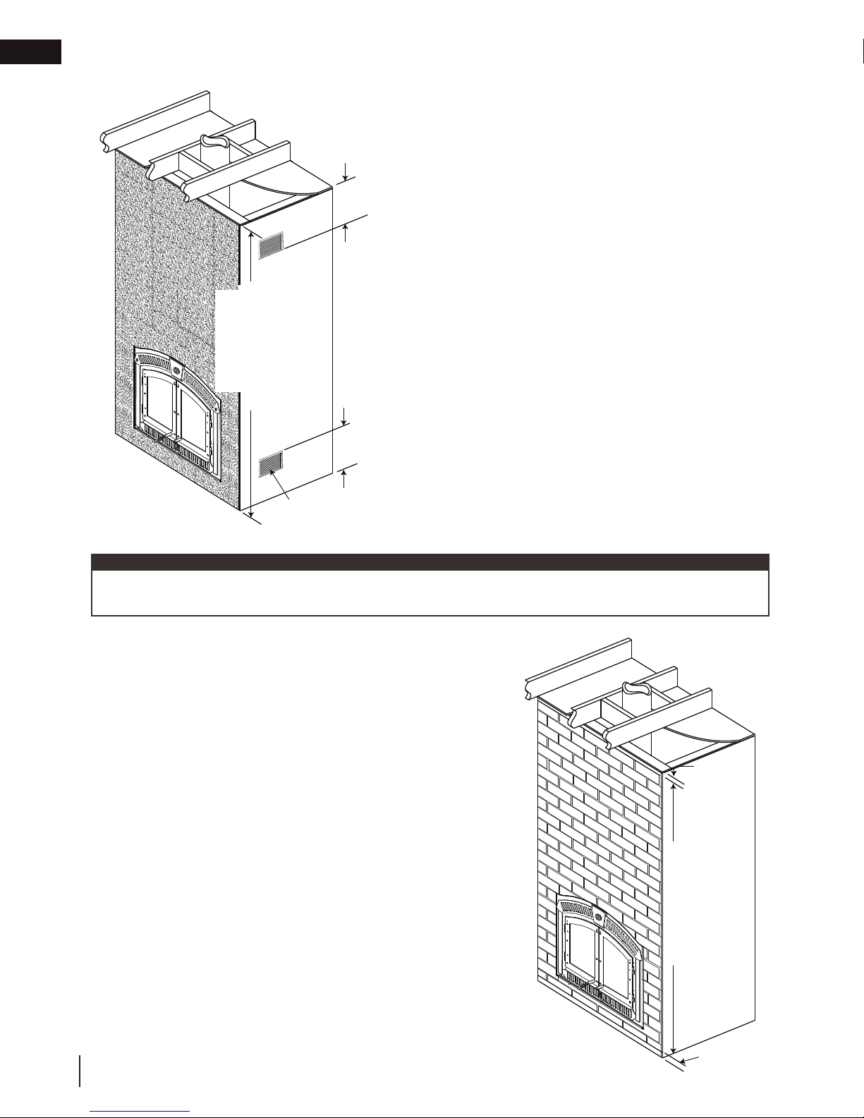
• Ventilation openings are required in enclosures up to 96” (244cm) high. They are recommended for all
enclosures above 84” (213.4cm), combustible fi nishing materials may be used on the front face.
• Use only a non-combustible material to fi nish the face of the appliance. A non-combustible material such as
cement board is required for this purpose.
• Do not insulate the steel body of the appliance.
The appliance is shipped with a template that is 1/8” (3.2mm) larger on the top,
bottom and each side than the faceplate. Leave the template in place when
installing the fi nishing material to ensure the faceplate will fi t inside the fi nishing
material edging.
TEMPLATE
note:
A ventilated
enclosure is
recommended.
See “ventilation
openings” section.
EN
DRYWALL
7 3/4"
(197MM)
MIN
EMBER STRIP
1
55
/2"
(1410MM)
TEMPLATE
40"
(1016MM)
3
/4"(197MM) MIN. CEMENT
7
BOARD FROM THE SIDE OF
THE UNIT TO COMBUSTIBLES
NON-COMBUSTIBLE
MATERIAL
84" MINIMUM
ENCLOSURE
HEIGHT WITH
VENTILATED
ENCLOSURE. SEE
VENTILATION SIZE
REQUIREMENTS.
Objects placed in front
of the appliance must
be kept a minimum of
48" (1219mm) away
from the front of the
appliance.
W415-1761 / B / 12.21.18
21
Page 22
EN
fi nishing
6.1 ventilation openings
84" MINIMUM
ENCLOSURE
HEIGHT WITH
VENTILATED
ENCLOSURE.
SEE VENTILATION
REQUIREMENTS.
12" (305MM)
MAXIMUM
SIZE
12" (305MM)
MAXIMUM
MINIMUM 40 SQUARE INCHES (1016MM) OF
VENTILATION OPENING REQUIRED, BOTH AT
THE TOP AND BOTTOM OF THE ENCLOSURE.
note:
As an alternate to grates, a 1” x 40” (25mm x 1016mm) wide gap can be left in the bottom and top of any
fi nishing material to circulate the air from the fl oor, around the apppliance and out the top.
1"(25MM)
OPEN
84" MINIMUM
ENCLOSURE
HEIGHT WITH
VENTILATED
ENCLOSURE.
SEE VENTILATION
SIZE
REQUIREMENTS.
22
W415-1761 / B / 12.21.18
1" (25MM)
OPEN
Page 23

fi nishing
6.2 baffl e installation
WARNING
!
• Operation of the appliance without the baffl es can result in excessive temperatures that could damage the
appliance, chimney and the surrounding enclosure.
• During shipping, the catalyst may have shifted from its proper location. Prior to initial burn, ensure the catalyst is
correctly installed. Refer to the “catalyst inspection and replacement” section.
CATALYST
The NZ3000H contains a ceramic
CATALYST SHIELD
CERAMIC FIBRE
BAFFLE
SECONDARY
AIR TUBES
ANDIRON
fi bre baffl e, catalyst and catalyst
shield. It is important that each of
these components are installed
correctly prior to operating the
appliance.
To install the ceramic baffl e, insert
it through the front of the appliance
and rest it on top of the secondary
tubes as far back as possible
ensuring proper orientation as
shown.
EN
To install the catalyst, refer to
the “catalyst inspection and
replacement” section in this
manual.
W415-1761 / B / 12.21.18
23
Page 24
EN
fi nishing
6.3 faceplate installation
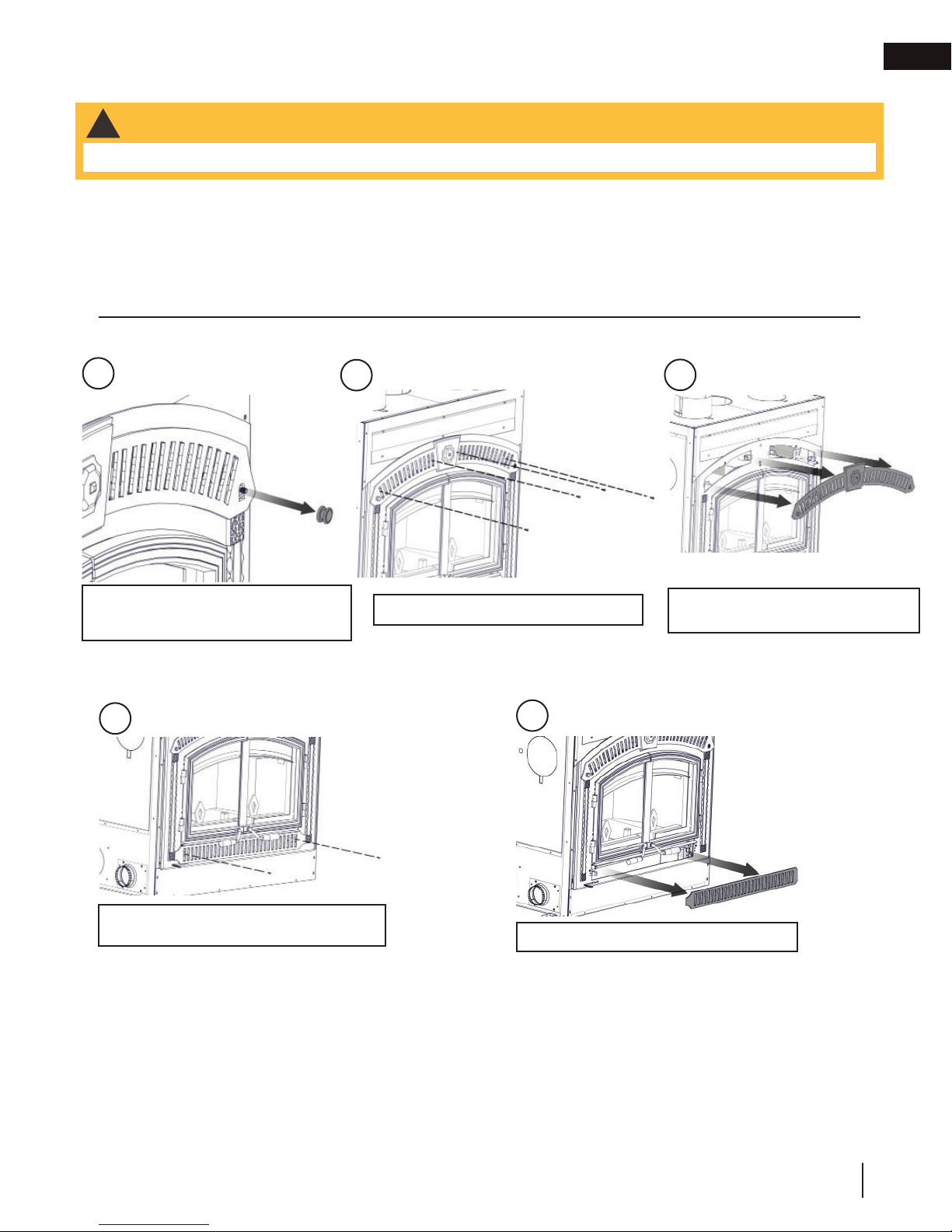
6.3.1 template removal
Template
Remove the screws and template,
discard only the template once all the
facing material has been installed.
Retain the screws for installing the
faceplate.
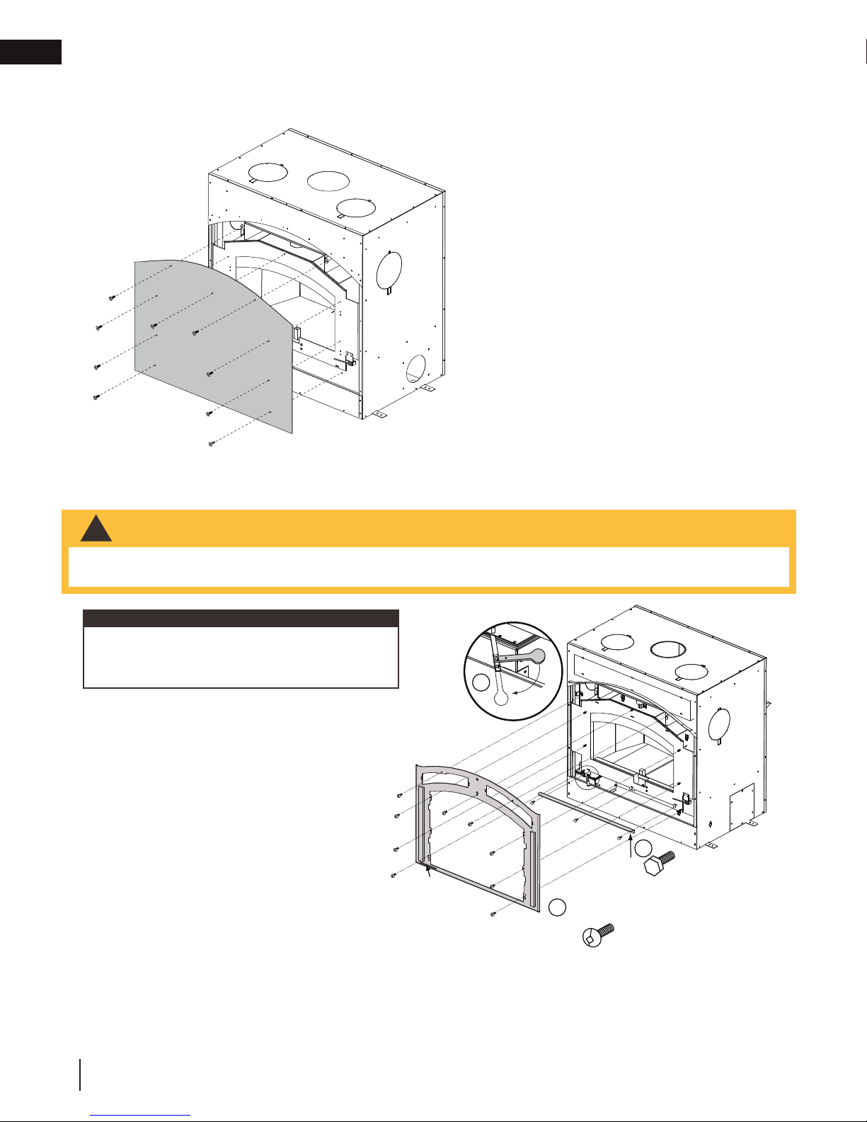
6.3.2 faceplate, hinge, ash lip and air control arm installation
WARNING
!
• Prior to installation, ensure the catalyst temperature monitor is installed. See “catalyst temperature monitor
installation” section for details.
note:
The FPWI3-H faceplate is shipped with the upper
and lower grilles assembled. Remove both grilles
before proceeding.
A. Assemble the air control arm by removing the 2nd
screw, rotating the arm in line and re-installing the
screw.
B. Install the ash lip.
1
+ -
A
AIR
CONTROL
SLOT
FRONT ARCHED
PAN EL X 9
-
+
M
R
A
L
O
R
T
N
O
I
C
R
2
ASH LIP X 3
3
24
W415-1761 / B / 12.21.18
Page 25

6.3.3 door installation
Left Door Right Door
fi nishing
EN
1. Install the left door handle through the left door
assembly. Secure using the lock washer and nut
provided.
**The fi nal angle of the left door handle should mirror
the right door handle in the closed position. Tighten
the nut to secure the handle at the desired angle.
1 2
Left Door Assembly
2. Install the right door handle through the right door
assembly.
Install the three fl at washers and the door latch as
illustrated.
Secure using the lock nut provided. Do not over
tighten. Handle must rotate freely.
Door latch adjustment may be required. Move one or
more washers as shown.
Right Door Assembly
**
Left Door
Handle
Washer
3
Nut
Lock
Latch
Lock
Nut
Flat
Washer
Right Door
Handle
Adjustment
W415-1761 / B / 12.21.18
25
Page 26
EN
fi nishing
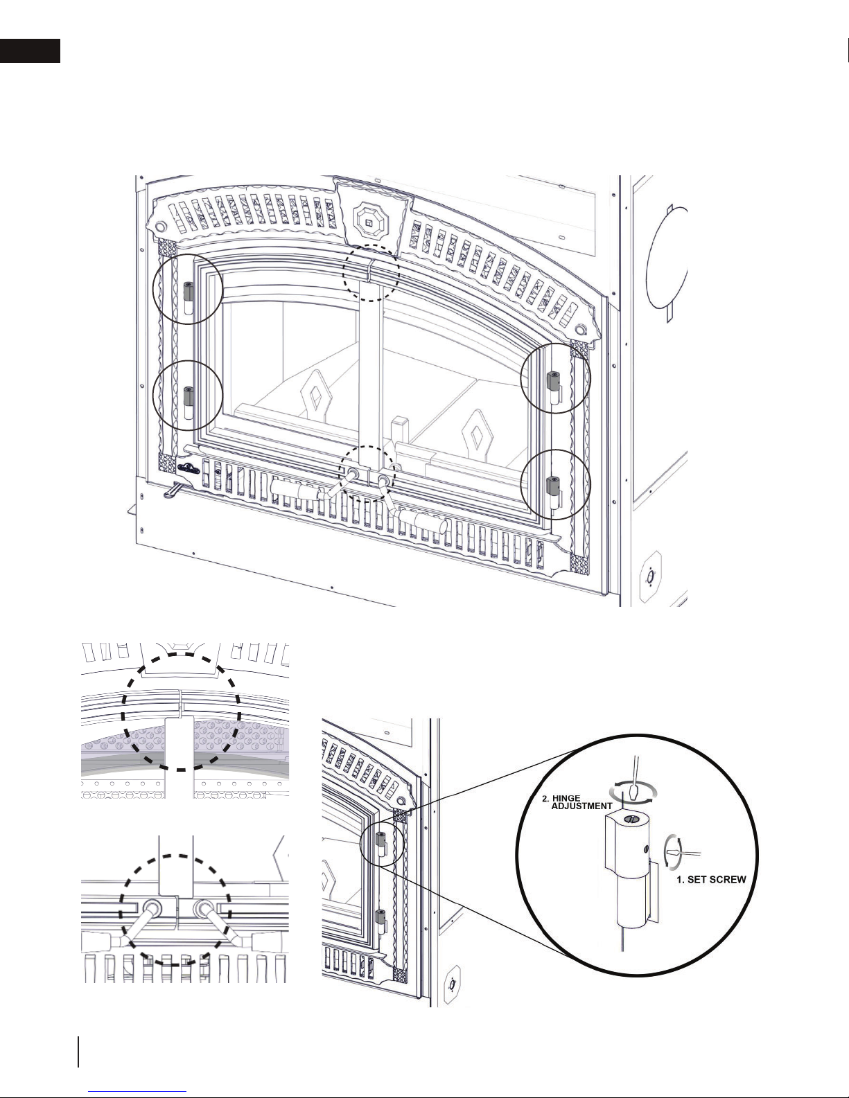
6.3.4 door gap adjustment
The door gap for the NZ3000H (see graphic below) can be set by adjusting the hinges of each door (x4). Each
hinge contains a set screw located on the side of the hinge. Loosen the set screw and turn the slotted hinge pin
to create an even gap. Each hinge can be adjusted independently.
Hinges X 4
Top Gap
Bottom Gap
Door gap and hinge location
26
W415-1761 / B / 12.21.18
Page 27
fi nishing
6.3.5 catalyst temperature monitor installation
WARNING
!
• It is important to install the catalyst temperature monitor prior to framing in the appliance completely.
Before installing the new catalyst temperature monitor, determine how the existing catalyst temperature monitor is
mounted.
The options for mounting are:
1. Wall mounted
2. Hearth mounted
If wall mounted, remove the top and bottom trim off of the appliance. If hearth mounted, remove bottom trim only.
Top Trim Removal
EN
A
Loosen set screw, unthread and
remove the knob on the right side of
the decorative trim.
Bottom Trim Removal
A
B
Unscrew the four retaining screws.
B
C
Pull decorative trim away from
appliance.
Remove the screws on the left & right
side of the decorative trim.
Pull decorative trim away from appliance.
W415-1761 / B / 12.21.18
27
Page 28

EN
fi nishing
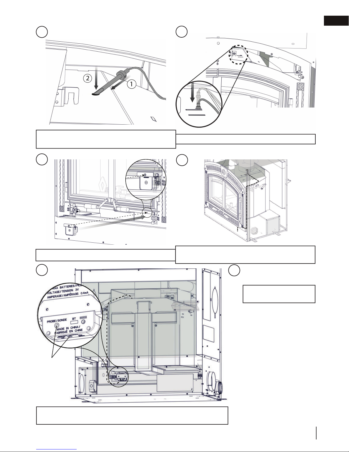
Installing the Catalyst Temperature Monitor
Slide the catalyst temperature monitor into the bracket
and attach with screws (supplied).
Setting depth of probe
A
Wire routing
A
B
Slide collet onto probe. Set the depth to 3.5” and secure with set screw.
B
28
W415-1761 / B / 12.21.18
Liberally spread stove cement (not supplied) along the
bottom of depth gauge.
Page 29
fi nishing
EN
C
Insert the probe on an angle and gradually straighten
the probe so that it aims down.
E
D
Slide the straightened probe into the hole.
F
Attach the bracket to the ash lip with screw (provided).
Ensure the catalyst temperature monitor indication light
is visible through the lower trim.
G
Rear view*
PROBE / SONDE
Attach the thermocouple to the designated port on the catalyst temperature
monitor. Only connect one thermocouple to the device.
H
Reinstall top and bottom
trim.
*Some components are hidden
for illustrative purposes.
W415-1761 / B / 12.21.18
29
Page 30

EN
fi nishing
6.4 optional NZ64 blower installation
WARNING
!
• All wiring should be done by a qualifi ed electrician and shall be in compliance with local codes and with the
current National Electric Code ANSI / NFPA No. 70-Current (in the United States), or, with the current C22.1
Canadian Electric Code (in Canada).
This appliance is supplied with two micro (pressure) switches and a thermally
activated switch.
note:
The blower on high will draw 3.0 amps using 120V or approximately
360 watts.
Ensure that the pressure switch actuating arm protrudes through the faceplate
when installed and moves freely.
The blower will only operate when the doors are fully closed and the air control
is set between “HIGH” and “LOW”.
Bump
High Low Extra Low
MODULATE BLOWER TO SUIT HEAT OUTPUT
30
W415-1761 / B / 12.21.18
Page 31

fi nishing
BLOWER INSTALLATION
note:
Consideration should be made for blower location as the closer to the appliance, the greater the air fl ow noise
will be. Blower may be installed on either side of the appliance.
A. Position the blower to an inside or outside wall into a framed
opening 12 3/8” wide by 10 1/2” high (314mm x 267mm).
(Outside wall not recommended in colder climates as cold air
may be drawn into the house even when the blower is off).
The blower housing should be installed onto a level surface
large enough to support the blower assembly. Allow for
fi nishing material when securing the blower housing, as the
grille mounts to the housing.
note:
Blower housing may be installed inside a home that has
suffi cient air fl ow.
COLLAR INSTALLATION
B. Determine which side of the appliance the blower is to be
located on. Remove and discard the cover plate and install
the 6” (152mm) collar.
EN
Secure by reaching through the collar and bending the tabs.
Use sealant to ensure that the connection is air tight.
ELECTRICAL CONNECTION
C. Remove the junction box covers on the appliance and the
blower. Removing the junction box cover on the appliance
exposes 4 black, labeled wires:
Appliance Junction Box
Two wires labelled “by-pass” - go to by-pass (summer) switch
(not supplied - overrides the thermally activated switch enabling
the user to run the blower without heat).
IMPORTANT: If the by-pass (summer) switch is not
desired, terminate the wires by attaching wire nuts to
by-pass (summer) switch wire leads separately (do not
connect together).
One wire labelled “blower” - connects to fan-speed control
rheostat and then the fan-speed control connects to the white
blower wire.
One wire labelled “L1” - connects to power (hot lead).
W415-1761 / B / 12.21.18
31
Page 32

EN
fi nishing
Blower Fan
Connections
- Removing the
junction box cover
on the blower
exposes 3 coloured
wires:
Pressure
Switch
One black wire
- connects to power
“L2” (neutral lead).
Thermodisc
One green wire
- connects to
ground.
Factory Wiring in Appliance
One white wire
- connects to the
fan-speed control, rheostat, or wall switch, or thermostat.
Main Power Supply
L1
L1
By-Pass
By-Pass
Blower
Appliance
Junction Box
Neutral
By-Pass
(Summer Switch)
Not supplied
Fan-speed Control
(Rheostat [variable
speed switch]) or wall
switch or thermostat
(Not supplied)
FAN
Field installed
Connection Point
INSTALL THE KB35AND
BY-PASS SWITCHES IN A
CONVENIENT LOCATION
FILTER
GRILL
ALLOW FOR
THICKNESS
OF FINISHING
MATERIAL
VENT CONNECTION
D. Connect the 6” (152mm) liner to the 6”(152mm) appliance collar and blower collars. Secure using 3 screws on
each end and seal with caulking. Liner stretches to a maximum of 10’ (3m).
GRILL AND FILTER INSTALLATION
E. Insert the fi lter into the grill. Foam gasket (1/2” [13mm] weather stripping) between the grill and blower housing
is recommended, but not supplied. The blower fi lter is washable. The bottom lip of the grill latches over the
bottom lip of the housing. Use two screws to secure the top of the grill to the facing.
note:
For complete installation instructions, refer to the blower kit.
32
W415-1761 / B / 12.21.18
Page 33

7.0 selecting wood
WARNING
!
• This appliance is designed to burn natural wood only. Do not burn treated wood, coal, charcoal, coloured
paper, cardboard, solvents or garbage. This appliance has not been tested with an unvented gas log set. To
reduce risk of fi re or injury, do not install an unvented gas log set into the appliance.
• Higher effi ciencies and lower emissions generally result when burning air dried seasoned hardwoods, as
compared to softwoods or too green or freshly cut hardwoods.
• Burning wet unseasoned wood can cause excessive creosote accumulation. When ignited, it can cause a
chimney fi re that may result in a serious house fi re.
• Do not store fuel within the clearance to combustibles, or in the space required for re-fueling and ash removal.
Before loading the appliance, ensure all required insulation and baffl es (if equipped) are installed and situated
properly. For maximum effi ciency, when the appliance is thoroughly hot, load it fully to the specifi ed maximum
amount and burn at a medium low setting (if equipped). The whiteness of the bricks and the cleanliness of the
glass are good indicators of your operating effi ciency. Not enough heat is produced when only a few pieces of
wood are burned or the wood may not burn completely.
note:
Appliances surrounded by solid rock or brick will experience a longer heat up period as those materials
absorb the heat being generated.
TYPES OF WOOD
Both hardwood and softwood burn
equally well in this appliance but
hardwood is denser, will weigh more per
cord and burn a little slower and longer.
Manufactured fi relogs made by
compressing 100% natural wood fi bre
can be safely used as fuel. Do not use
manufactured fi relogs if they contain
additives such as paraffi n, wax, binders
etc. Never burn more than two manufactured fi relogs at a time.
MOISTURE CONTENT
Burn only dry, clean unpainted wood that has been seasoned. It produces more heat and less soot or
creosote. Freshly cut wood contains about 50% moisture while after proper seasoning only about 20% of the
water remains. As wood is burned, this water boils off consuming energy that should be used in heating. The
wetter the wood, the less heat is given off and the more creosote is produced. Dry fi rewood has cracks in the
end of the grain.
STORING WOOD
Firewood should be split and stacked in a manner that allows for full air circulation and covered in early spring
to be ready for burning that fall. Dry fi rewood has cracks in the end grain.
Cut the wood so that it will fi t horizontally, front to back, making for easier loading and less of a likelihood that
the wood will roll onto the glass.
Fuel for the appliance must not be stored closer than the required clearances to combustibles (heat sensitive
material). NEVER STORE WOOD IN THE ASH PAN COMPARTMENT (if applicable).
selecting wood
EN
W415-1761 / B / 12.21.18
33
Page 34

EN
operation
8.0 operation
WARNING
!
• The wood heater has a preset minimum low burn rate that must not be altered. It is against United States
Federal regulations to alter this setting or otherwise operate this wood heater in a manner inconsistent with
instructions in this manual.
Expansion / contraction noises during heating up and cooling down cycles are normal and to be expected.
TIPS FOR BURNING:
• Create a large fi re to heat up the appliance before closing bypass door and adjusting to a slower burn.
• To create a large, quick burning fi re, use small pieces of wood.
• For a lower, but extended burn, stack larger pieces of wood close together.
• For long burns, leave a 1” (25mm) - 2” (51mm) bed of ashes.
• Burn dry wood only.
• With the exception of overnight burns, create large, quick burning fi res whenever possible. Smaller, slow
burning fi res using large logs will cause the glass to become dirty. Larger, quick burning fi res using medium
sized wood to refuel frequently are much more effi cient.
• It is important to minimize visible smoke emitting from the chimney. Burning seasoned fi rewood, maintaining
the appliance catalyst and following the operating instructions contained within this manual will ensure that
visible smoke emissions are minimized.
DO’S
• Verify with a moisture meter that wood contains no
more than 20% moisture content.
• Burn several pieces of medium sized wood as they
are better than a few big pieces.
• Clean chimney regularly.
• Refuel frequently using medium sized wood.
• “Fine tune” the air settings (if applicable) for optimum
performance.
DONT’S
• Take ash out immediately. Let it accumulate to a
depth of at least one inch. A good ash layer provides
for a longer lasting and better burning fi re.
• Burn wet wood with more than 20% moisture
content.
• Close the door too soon or damper down too
quickly.
• Burn one large log rather than two or three smaller
sized logs.
• Burn at continually “low setting” (if applicable), if
glass door is constantly blackened. This means the
fi rebox temperature is too low.
8.1 appliance operation
Primary combustion air enters through the air control inlet box regulated by a draft control, travels up the side
through a duct and enters the top centre of the combustion chamber into a preheating airwash located across the
top and then down the window to feed the fi re and also to ensure that the glass remains clean.
Secondary air feeds directly into the combustion chamber at hearth level then travels to the secondary air
chamber which injects the air to oxidize the unburnt gases rising to fl ue. During start up and refueling, the bypass
door must be opened to circumvent the catalyst until operating temperatures are achieved.
34
W415-1761 / B / 12.21.18
Page 35

operation
8.2 bypass door
The bypass door is an internal mechanism that allows the exhaust products to travel through an unobtrusive path
to the fl ue prior to engaging the catalyst.
The bypass door is operated by pulling the bypass rod located on the right side of the appliance out and down
until it catches and remains open. To shut the bypass door, pull the rod out and up allowing the rod to slowly
retract into the appliance. Be sure not to allow the bypass door to slam shut.
The bypass pull handle tool must be used with your appliance for adjusting the bypass rod. This tool will prevent
injury as the bypass rod becomes extremely hot as the appliance heats up. When you receive your appliance,
the bypass rod tool will come unassembled. It can be easily assembled by screwing the spiralled handle onto the
body of the tool.
Engage tool into the groove of the bypass rod
handle.
EN
1 2
Ensure bypass door is open during startup and re-
fueling. See above for bypass door rod location.
3 4
Pull bypass rod outwards.
When hot, use tool provided.
Press bypass rod downwards then inwards to lock into
place.
Open fi rebox doors and load fuel.
W415-1761 / B / 12.21.18
35
Page 36

EN
operation
8.3 catalyst
This catalytic heater is equipped with a temperature probe to monitor catalyst operation. The catalyst is an
integral part of this appliance. It is imperative to inspect and maintain the catalyst to help sustain optimal effi ciency
and emission levels. Catalyst operating temperatures range from 500ºF to 1,400ºF (260ºC to 760ºC); operating
the appliance with the catalyst temperature above the maximum for a prolonged period will cause permanent
damage. The supplied catalyst temperature monitor will indicate the catalyst temperature using an LED light.
Please refer to operating instructions provided with the catalyst temperature monitor.
8.4 operating sounds, smells and characteristics
If a blower is installed, slight humming sound may be heard depending on the location of the blower. The sound may
be minimized by turning down the blower speed. It is also normal during operation to hear creaking and/or ticking
sounds as the metal plate components of the appliance expand and contract. This may be present during both
warm up and cool down periods.
During the break-in period (the fi rst 2 or 3 fi res) create only small, hot fi res using kindling. This will allow the fi rebrick
to cure. Do not be alarmed if small hairline cracks develop in the fi rebrick. This is a normal occurrence and does not
pose a safety hazard. During this time the paint may also emit an odour as it cures and you may wish to open a door
or window to alleviate the smell.
There are many different ways to start a fi re, review the hints and warnings in this section to ensure the fi re is started
properly.
8.5 air control
WARNING
!
• Always operate this appliance with the door closed and latched except during start-up and re-fueling.
Draft is the force which moves air from the appliance up through the chimney. The amount of draft in your chimney
depends on the length of the chimney, local geography, nearby obstructions and other forces.
Inadequate draft may cause back-puffi ng into the room and may cause plugging of the chimney. Too much draft may
cause an excessive temperature in the appliance, glowing red appliance parts or an uncontrollable burn which can all
lead to a chimney fi re or a permanent damage to the appliance.
The wood heater has a preset minimum low burn rate that must not be altered. It is against United States Federal
regulations to alter this setting or otherwise operate this wood heater in a manner inconsistent with instructions in
this manual.
8.6 fi re extinguishers / smoke and carbon monoxide detectors
All homes with a solid fuel burning appliance should have at least one fi re extinguisher in a central location,
known to all, at least one smoke detector and carbon monoxide (CO) detector in the room containing the
appliance. If the smoke detector sounds an alarm, correct the cause but do not deactive or relocate the smoke
detector. If the carbon monoxide detector sounds an alarm, immediately vent the area, evacuate and call your
local fi re department.
36
W415-1761 / B / 12.21.18
Page 37

operation
8.7 fuel loading and burn cycle
WARNING
!
• Burn wood behind the log retainer directly on the fi rebricks. Do not use elevated grate or otherwise raise the
fi r e .
• Do not store wood within appliance installation clearances or within the space required for re-fueling and ash
removal.
• Burning wet, unseasoned wood can cause excessive creosote accumulation, which, when ignited, can cause
a chimney fi re that may result in a serious house fi re.
When operating the appliance effi ciently, the bricks will be nearly all white and the glass mostly clear. The whiteness of the bricks and the cleanness of the glass are good indicators of your operating effi ciency.
Not enough heat is produced when only one or two pieces of wood are burned.
A minimum of three pieces are needed to encase a bed of coals that sustains the fi re. Loosely stacked wood
burns quicker than a tightly packed load.
A fl ash fi re is a small fi re burned quickly when you don’t need much heat. After your kindling has “caught”, load
at least 3 pieces of wood, stacked loosely. Burn with the draft control fully open or closed only slightly.
Wood burns in cycles rather than giving a steady output of heat. It is best to plan these cycles around your
household routine so that only enough coals are left to start the next load.
EN
SUFFICIENT FIREWOODINSUFFICIENT FIREWOOD
W415-1761 / B / 12.21.18
37
Page 38

EN
operation
8.8 lighting a fi re
WARNING
!
• Always operate this appliance with the door closed and latched except during start up and re-fueling or
unless otherwise noted with compatible Wolf Steel approved accessories. Burning your appliance with the
doors open or ajar creates a fi re hazard that may result in a house and/or chimney fi re. Always wear gloves to
prevent injury. Do not leave the fi re unattended when the door is unlatched or when using a spark screen as
unstable wood could fall out of the fi re chamber creating a fi re hazard to your home.
• Never leave children unattended when there is a fi re burning in the appliance.
• Never use gasoline-type lantern fuel, kerosene, charcoal lighter fl uid, or similar liquids to start or “freshen up” a
fi re in this appliance. Keep all such liquids well away from the appliance.
• This appliance has not been tested with any vented or unvented gas log set. To reduce risk of fi re or injury, do
not install a vented or unvented gas log set into this appliance.
Make sure the air control lever is set to high and, if equipped, the bypass door is open. You may also open the doors 1”
(25mm) to 2” (51mm) during the fi rst fi ve minutes of start-up, if additional air is needed see “combustion air” section.
Remove all source of gasoline or other fl ammable vapours and liquids in the vicinity of this or other
appliances prior to lighting.
Use plenty of newspaper and kindling to ensure the appliance quickly reaches a proper temperature. Once the
kindling is burning rapidly, place a few larger pieces of wood onto the fi re.
Tip: When fi rst lighting a fi re, if the smoke is not quickly drawn into the chimney, there may be a downdraft or cold
air in the chimney. By fi rst burning large amounts of crumpled newspaper, the chimney will get heated and the smoke
will quickly vent up the chimney.
To start, a brisk fi re is required.
A.
Roll up some newspaper (loosely
crumpled), light it and place it near
the appliance fl ue until the chimney
begins to draw.
Draft is the force which moves air from the appliance up through the chimney. The amount of draft in your chimney
depends on the length of the chimney, local geography, nearby obstructions and other forces.
Inadequate draft may cause back-puffi ng into the room and may cause plugging of the chimney. Too much draft may
cause an excessive temperature in the appliance, glowing red appliance parts or an uncontrollable burn which can all
lead to a chimney fi re or a permanent damage to the appliance.
B. Cover with dry kindling. C. Light the paper and when the
kindling is burning add more fuel.
38
W415-1761 / B / 12.21.18
Page 39

operation
EN
D. To maintain a brisk fi re, a hot
coal bed must be established
and maintained.
When a fi re is burning, open the doors slowly to avoid drawing smoke into the room.
Closing the doors too quickly after refuelling will reduce the fi rebox temperature and may result in an
unsatisfactory burn.
G. As soon as the doors are closed, you will observe a change in
the fl ame pattern. The fl ames will get smaller and lazier because
less oxygen is getting into the combustion chamber. The fl ames,
however, are more effi cient. The fl ames will remain lazy but
become larger again as soon as the fi rebricks have been heated
thoroughly and the chimney becomes heated and provides a good
draft.
H. With the doors opened, the fi re is wastefully drawing heated room
air up the chimney which is certainly not desirable. Always operate
with the doors fully closed once the medium sized logs have
caught fi re.
You can now add larger pieces of wood and operate the appliance
normally. Once the appliance is entirely hot, it will burn very
effi ciently with little smoke from the chimney. There will be a bed of hot
coals in the fi rebox so you can safely fi ll the fi rebox with wood to the top
of the andirons.
Can't get the appliance operating? Use more kindling and paper.
Assuming the chimney and vent are sized correctly and there is suffi cient
combustion air, the lack of suffi ciently dry quantities of small kindling is the
problem. Thumb size is a good gauge for small kindling diameter.
Can't get heat out of the appliance? One of two things may have
happened. The appliance door may have been closed prematurely and
the appliance itself has not reached optimum temperature.
Re-open the door and/or draft control to re-establish a brisk fi re. The other
problem may have been wet wood. The typical symptom is sizzling wood and
moisture being driven from the wood.
The only accurate way to determine wood moisture is with a moisture meter.
Contact your local dealer for more information.
note:
Appliances surrounded by solid rock or brick will experience a longer
heat up period as those materials absorb the heat being generated.
E. Slowly add larger wood (2x4 size
pieces). Lay the pieces lengthwise
from side to side in the hot
coal bed with a shallow trench
between, so that the primary air
can fl ow directly into this trench
and ignite the fuel above.
F. When the fi re seems to be at its
peak, medium sized logs may
be added. Once these logs have
caught fi re, carefully close the
doors.
OPERATING WITH DOOR CLOSED
OPERATING WITH DOOR OPEN
W415-1761 / B / 12.21.18
39
Page 40

EN
operation
8.9 smoking
A properly installed appliance should not smoke. If yours does, check the following:
• Has the chimney had time to get hot?
• Is the smoke passage blocked anywhere in the appliance, chimney connector or chimney?
• Is the room too airtight and the air intake not connected to the outside? Try with a window partly open.
• Is the smoke fl ow impeded by too long a horizontal pipe or too many bends?
• Is it a weak draft perhaps caused by a leaky chimney, a cold outside chimney, too large a diameter of a
chimney, too short a chimney, or a chimney too close to trees or a higher roof?
• Is the moisture content of the wood greater than 20%?
• If equipped, has the catalyst bypass been closed or closed prematurely?
8.10 overnight burn
A. Get the appliance hot by moving the air control to high and letting
the appliance burn for 15 minutes.
B. Load your larger pieces of wood compactly, packed close enough
to prevent the fl ames from penetrating it completely.
C. After approximately 30 minutes, depending on the size of the load,
reduce the draft control setting making sure that the fi re is not
extinguished.
D. In the morning, the appliance should still be hot, with embers in
the coal bed. Stir the coals and load small pieces of wood to reignite the fi re, if desired.
NOTE: Differences in chimney height and draft may lower overall burn times.
DO NOT OVERFIRE THE APPLIANCE! Overfi ring can occur by burning large amounts of smaller wood pieces
or vigorously burning large loads of wood with the draft control on "HIGH" (fully open) for long
periods of time (one or two hours).
8.11 re-loading the appliance
WARNING
!
• Burning wet, unseasoned wood can cause excessive creosote accumulation, which, when ignited, can cause a
chimney fi re that may result in a serious house fi re.
• It is recommended to use heat-resistant gloves and/or metal tongs when reloading the appliance.
When refuelling, open the door slowly to prevent smoke spillage. Use a pair of long appliance gloves when
feeding the fi re. Keep a small steel shovel nearby to use as a poker and to remove ashes. Do not store wood
within 4 feet (1.2m) of the appliance.
Follow the directions below to minimize smoke spillage while re-loading the appliance.
1. Move the air control to high.
2. Open the bypass door, if equipped.
3. Open the glass door slightly. Allow the airfl ow inside the fi rebox to stabilize before opening the doors
fully.
4. Load wood and burn at a medium low setting.
5. After 5-10 minutes, close the glass doors.
6. Ensure catalyst temperature is stable then shut bypass door, if equipped.
In the evening, load your appliance at least a half-hour before bed to ensure the fi re is hot enough to close the
draft control for an overnight burn, refer to the “overnight burn” section for detailed information.
40
W415-1761 / B / 12.21.18
Page 41

9.0 maintenance
maintenance
9.1 ash removal procedures
WARNING
!
• Improper disposal of ashes results in fi res. Do not discard ashes in cardboard boxes, dump in backyards, or
store in garages.
• If using a vacuum to clean up ashes, be sure the ashes are entirely cooled. Using a vacuum to clean up warm
ashes could cause a fi re inside the vacuum.
A bed of ashes approximately 1” (25.4mm) deep
should be left on the fi rebox bottom to help
maintain a hot charcoal bed. When the fi re has
burned down and cooled, remove any excess
ashes. To remove the ash, follow the directions
below.
A. After the last coal has extinguished, let the
appliance cool at least two hours.
B. Open the appliance doors.
C. Scoop the ash from the fi rebox into a
metal, airtight container with a lid. Cover
the container with the lid and move the
container away from the appliance onto a
suitable non-combustible surface to ensure
the ashes cool. Dispose of the ashes.
EN
9.2 catalyst inspection and replacement
note:
The combustor supplied with this heater is an ACI brand long life ceramic combustor.
WARNING
!
• Do not remove catalyst unless you are replacing with an approved kit.
It is recommended that the catalyst be inspected at the beginning, middle and at the end of each season for
issues or defects such as cracks, crumbling, creosote / soot buildup and peeling of the catalyst coating. Not all
catalyst defects may be visually apparent - please refer to the “troubleshooting” and “catalyst troubleshooting”
sections of this manual for further appliance symptoms, causes and corrective actions.
You can get an indication of whether the catalyst is working by comparing the amount of smoke coming out
of the chimney after the catalyst has hit light off temperatures with the bypass open and the smoke not being
routed through the combustor and then with the bypass closed and the smoke going through the combustor.
Signifi cantly more smoke will be seen when the exhaust smoke is routed through the bypass when a combustor
is working. If this is not the case, refer to the “troubleshooting” and “catalyst troubleshooting” sections regarding
catalytic maintenance.
The life span of the catalyst depends on many factors such as type of wood burned, frequency of appliance use,
maintenance of appliance, etc. However, with proper inspection and maintenance, a catalyst should last between
6 to 10 years.
If replacement of the catalyst is necessary, please refer to the instructions supplied below or the replacement
catalyst kit.
W415-1761 / B / 12.21.18
41
Page 42

EN
maintenance
WARNING
!
• Always check the wood heater has been cooled suffi ciently before attempting to change any components
within the fi rebox.
12
Locate the ceramic fi bre baffl e. Slide baffl e forward and down to remove.
34
Locate the ceramic fi bre baffl e. Move perforated catalyst shield up and over shoulder
bolts.
5
6
Pivot the perforated catalyst shield forwards until it is
facing downwards.
42
W415-1761 / B / 12.21.18
Pivot the perforated catalyst shield forwards until it is
facing downwards.
Page 43

maintenance
EN
7
Grab the steel tabs located on either side of the
catalyst.
9
8
Slide the catalyst forward and out. The steel tabs are
friction held and will separate from the catalyst when
pulled out.
10
Holding the steel tabs located on either side of the
catalyst, slide the new catalyst into the cavity.
TIP: Securing tabs with masking tape may aid
installation.
Reinstall perforated catalyst shield in reverse.
Ensure basket rests on shoulder bolts from Step 2. Reinstall fi bre baffl e.
Tips for prolonging catalyst life:
• Do not overfi re the appliance.
• Monitor catalyst temperatures.
• Avoid thermal shock (heating or cooling catalyst too quickly).
• Inspect catalyst regularly.
• Do not burn anything other than high quality wood mentioned in this manual.
W415-1761 / B / 12.21.18
43
Page 44

EN
maintenance
9.3 creosote formation and removal
When wood is burned slowly, it produces tar and other organic vapors, which combine with expelled moisture
to form creosote. The creosote vapors condense in the relatively cooler chimney fl ue or a slow-burning fi re. As a
result, creosote residue accumulates on the fl ue lining. When ignited, this creosote makes an extremely hot fi re.
The chimney connector and chimney should be inspected at least once every two months during the heating
season to determine if a creosote buildup has occurred.
If creosote has accumulated, it should be removed to reduce the risk of a chimney fi re.
9.4 run-away or chimney fi re
WARNING
!
• A chimney fi re can permanently damage your chimney system. This damage can only be repaired by replacing
the damaged component parts. Chimney fi res are not covered by the lifetime limited warranty.
CAUSES:
• Using incorrect fuel, or small fuel pieces which would normally be used as kindling.
• Creosote build up in chimney.
• Leaving the door ajar too long and creating extreme temperatures as the air rushes in the open door.
• If equipped, burning your appliance with the ash plug not securely seated.
SOLUTIONS:
• Do not burn treated, painted, artifi cial, paper or processed wood logs, coal, charcoal, coloured paper or
cardboard.
• Have chimney regularly cleaned.
• Be careful not to over-fi re the appliance by leaving the door open too long after initial start-up. A
thermometer on the chimney connector and/or appliance top helps to indicate the appliance operating
temperature.
• If equipped, always operate the appliance with the ash plug properly installed.
IN CASE OF A CHIMNEY FIRE:
• Close glass door and air control (and damper, when equipped).
• Have a well understood plan for evacuation and a place outside for everyone to meet. Prepare to evacuate
to ensure everyone’s safety.
• Call local fi re department. Have a fi re extinguisher handy. Contact local authorities for further information on
how to handle a chimney fi re.
• After the chimney fi re is out, clean and inspect the chimney or chimney liner for stress and cracks prior to
lighting another fi re. Also check combustibles around the chimney and the roof.
9.5 chimney cleaning
Both the chimney and the appliance must be inspected and cleaned if necessary at least once a year.
For serious wood burners, chimney cleaning must be done as needed to avoid chimney fi res; the venting
systems for controlled combustion appliances may need cleaning as often as once a month. These rates,
however, depend on the burning habits of the individual operating the appliance. For example, it is possible to
clog a solid fuel appliance chimney in a few days if slow, smoldering fi res are burned and the chimney is cold.
note:
Appliances burned consistently without hot fi res may result in signifi cant creosote accumulations in the
chimney.
Certain items and considerations are important in chimney cleaning:
• Proper tools should be used, including a brush specifi cally designed for chimney cleaning.
• The chimney connector and dampers as well as the chimney should be cleaned.
• The appliance’s fi rebox and baffl e system should be cleaned if needed.
• The chimney should be inspected and repairs made if needed, preferably by a qualifi ed chimney sweep
or mason.
44
W415-1761 / B / 12.21.18
Page 45

maintenance
9.6 cast iron door glass and gasket replacement
Remove the doors from the appliance (if necessary, refer to your door installation instructions). Place the doors
face down on a protected surface to avoid any damages.
INSTALLATION INSTRUCTIONS FOR THE RIGHT DOOR:
A. Remove the damaged gasket.
B. Apply a thin bead of adhesive (red
high temperature silicone [RTV]
or wood stove gasket cement) in
the top, side and bottom gasket
grooves. The adhesive should follow
the same path as the gasket, as
shown.
C. Wrap a piece of tape around one
end of the 1/2” (13mm) gasket and
cut through the center. This will stop
the gasket from fraying.
D. Place the taped end of the gasket
into the groove, ensure it remains
1/2”(12.7mm)
fl ush with the side of the door
(recessed point). Without stretching
or compressing the gasket, place
it naturally along the top, side and
bottom gasket grooves and into the
adhesive, as shown.
E. When you reach the end point, wrap
a piece of tape around the gasket
and cut through the center, ensuring
the gasket is fl ush wtih recessed point, as shown above.
GASKET
TAPE
TAPE
EN
INSTALLATION INSTRUCTIONS FOR THE LEFT DOOR:
A. Remove the damaged gasket.
B. Apply a thin bead of adhesive (red high
temperature silicone [RTV] or wood stove gasket
cement) in the top, sides and bottom gasket
grooves. The adhesive should follow the same
path as the gasket illustrated in Figures 1 and 2.
C. Wrap a piece of tape around one end of the 1/2”
(13mm) gasket and cut through the center. This
will stop the gasket from fraying.
D. Place the taped end of the gasket centered
in the groove at the bottom of the door.
Without stretching or compressing the
gasket, lay it naturally into the groove, on top
of the adhesive as a continuous loop, as shown in
Figures 1 and 2.
1/2”(12.7mm) GASKET
1/2”
(12.7mm)
GASKET
TAPE
TAPE
FRONT SIDE
REAR SIDE
When you return to the other end of the gasket wrap a
piece of tape around the other end of the gasket and cut
through the center, refer to Figures 1 and 2.
W415-1761 / B / 12.21.18
45
Page 46

EN
maintenance
9.7 internal gasket replacement
WARNING
!
• All internal components are heavy. It is recommended to provide support for components where needed when
installing.
It is recommended that the gaskets of your appliance be replaced every 6-10 years or when stove emissions
seem to increase.
12
Remove all brick panels. See Step 2 for removal order. Remove brick in order illustrated above.
34
Remove front two nuts and bolts as illustrated above.
5
6
Remove two rear bolts.
x2
Slide secondary air manifold downward and out to
remove. Scrape off gasket from rear and clean surface.
Secure new gasket with high temperature silicone (not
supplied).
46
W415-1761 / B / 12.21.18
Reach in through the opening of the bypass door to
access fasteners.
Page 47

maintenance
78
EN
Remove nuts and bolts on either side of appliance
while supporting the baffl e.
9
Open door to baffl e.
Lower baffl e.
10
C
A B
Remove gaskets A, B, and C.
1211
A B
Replace gaskets A, B, and C. Secure with stove
cement (not supplied).
C
Locate Gasket D.
W415-1761 / B / 12.21.18
47
Page 48

EN
maintenance
13
14
D
Open dilution door and remove gasket.
Apply new gasket using stove cement (not supplied) to secure. This is to prevent the ends from fraying and
locking the gasket into position of the gasket groove.
15
After installing gaskets, follow Steps 1-8 in reverse to reinstall components.
48
W415-1761 / B / 12.21.18
Ensure smooth operation of bypass door.
Page 49

maintenance
9.8 care of glass
WARNING
!
• Do not clean glass when hot! Do not use abrasive cleaners to clean glass.
If the glass is not kept clean, permanent discolouration and/or
blemishes may result. Normally a hot fi re will clean the glass. The
most common reasons for dirty glass include:
• Not using suffi cient fuel to get the appliance thoroughly hot.
• Using green or wet wood.
• Closing the draft so far that there is insuffi cient air for complete
combustion.
If it is necessary to clean the glass, buff lightly with a clean dry cloth and non-abrasive cleaner. Clean the glass
after the fi rst 10 hours of operation with a recommended appliance glass cleaner. Thereafter, clean as required.
The glass is very strong, but do not let burning fuel rest or fall against it and always close the door gently.
NEVER FORCE OR SLAM IT SHUT!
Do not operate the appliance with broken glass, as leakage of fl ue gases may result.
Contact your local authorized dealer/distributor for complete cleaning instructions.
WARNING
!
HOT GLASS WILL CAUSE
DO NOT TOUCH GLASS UNTIL
NEVER ALLOW CHILDREN TO
BURNS.
COOLED.
TOUCH GLASS.
EN
If the glass should ever crack or break while the fi re is burning, do not open the door until the fi re is out. Do not
operate the appliance until the glass has been replaced. Contact your local authorized dealer/distributor for
replacement parts. DO NOT SUBSTITUTE MATERIALS.
9.9 care of catalyst
WARNING
!
• This wood heater contains a catalytic combustor, requiring periodic replacement and regular inspection for
proper operation. It is against United States Federal regulations to operate this wood heater in a manner
inconsistent with operating instructions in this manual. This includes the removal or deactivation of the catalytic
element.
Periodic inspection of the catalytic combustor is needed to ensure proper functioning of the appliance and also to
determine when replacement is required. Creosote buildup, increase in emissions and a loss of heat effi ciency will
result from a non-functioning combustor appliance.
Catalytic combustors should remain active under normal operating conditions for a period of six to ten years. This
will be determined by the quality and the amount of wood burned.
9.10 care of plated parts
If the appliance is equipped with plated parts, you must clean fi ngerprints or other marks from the plated surfaces
before operating the appliance for the fi rst time. Use an ammonia-free or vinegar-based cleaner and a towel
to clean. If not cleaned properly before operating for the fi rst time, the marks can cause permanent blemishes
on the plating. After the plating is cured, the fi ngerprints and oils will not affect the fi nish and little maintenance
is required, just wipe clean as needed. Prolonged high temperature burning with the door ajar may cause
discolouration on plated parts.
note:
The protective wrap on plated parts is best removed when the assembly is at room temperature but this can
be improved if the assembly is warmed (i.e. using a hair dryer or similar heat source).
W415-1761 / B / 12.21.18
49
Page 50

EN
maintenance
9.11 NZ64 blower replacement
A. Remove the grill and fi lter by removing the 2 securing screws.
B. Remove the nut securing the blower bracket to the housing.
C. Lift the handles to pull the blower and bracket off of the stud.
D. Slide the bracket and blower out of the housing.
E. Disconnect the wire connector from the blower.
F. Remove the old blower from the bracket by removing the four
screws.
G. Secure the new blower to the existing bracket using the four
screws.
H. Slide the new blower / bracket assembly into the housing. Ensure
that the blower bracket slides into the clips at the back of the
housing on either side.
I. Push the assembly into the housing as far in as possible.
J. Secure the assembly to the housing using the nut removed in step
B.
K. Re-secure the grill by replacing the 2 securing screws.
NUT
BLOWER
BRACKET
STUD
HANDLES
HOUSING
CLIP
BLOWER/BRACKET ASSEMBLY
50
W415-1761 / B / 12.21.18
Page 51

10.0 replacement parts
k
k
k
k
k
A
WARNING
!
• Failure to position the parts in accordance with this manual or failure to use only parts specifi cally approved
with this appliance may result in property damage or personal injury.
Contact your dealer for questions concerning prices and policies on replacement parts. Normally, all parts can
be ordered through your Authorized dealer / distributor.
For warranty replacement parts, a photocopy of the original invoice will be required to honour the
claim.
When ordering replacement parts always give the following information:
• Model & Serial Number of appliance
• Installation date of appliance
• Part number
• Description of part
• Finish
Parts, part numbers, and availability are subject to change without notice.
Parts identifi ed as stocked will be delivered within 2 to 5 business days for most delivery
destinations.
Parts not identifi ed as stocked will be delivered within a 2 to 4 week period, for most cases.
Parts identifi ed as ‘SO’ are special order and can take up to 90 days for delivery.
maintenance
EN
10.1 overview
Ref. No.
1
2
3
4
5
6
7
8
9
10
11
12
13
14
15
16
17
18
18
19
Part NumberDescription
W010-1854
W010-3017
W010-3931-SER
W010-3794-SER
W010-3837
W010-3840-SER
W018-0183
W035-0417-SER
W080-1637
W090-0146
W090-0150
W090-0151
W090-0321
W090-0310
W090-0311
W090-0312
W137-0003-SER
W370-0081
W370-0083
W370-0082
Stocked
Sensor bracket assembly
Wire harness assembly
Secondary air assembly
Pilot tube assembly
Dilution air door assembly
Bypass door bracket assembly
Fibre baffle
Cast baffle base
Shaft rod bracket
Front left bric
Base brick (RS)
Base brick (LS)
Front right bric
Front side bric
Side bric
Rear bric
Catalyst replacement kit
Cast door (LS) BK
Cast door (LS) WI
Cast door (RS) BK
Ye s
Ye s
Ye s
Ye s
Ye s
Ye s
Ye s
Ye s
Ye s
Ye s
Ref. No.
19
20
21
22
23
24
25
25
26
27
27
28
29
30
31
32
33
34
35
36
Part NumberDescription Stocked
W370-0084
W225-0370 Cast bypass door
W300-0134-SER
W330-0072
W370-0075
W370-0076
W370-0077
W370-0078
W370-0079
W380-0031BK-SER
W380-0031W-SER
W485-0043
W555-0097
W562-0004-SER
W580-0013
W585-0853
W685-0002
W715-0773-SER
W720-0171-SER
Cast door (RS) WI
Main door glass (c/w gasket)
Main door hinge
Firebox gasket hardware kit
Bypass shaft kit
Cast door handle kit WI
Cast door handle kit BK
Gasket 1/2” dia. rope kit
Black knob assembly
Wrought iron knob assembly
Hinge pin
Bypass opening rod
Gasket, 3/4” channel
Bypass opening shaft
Catalyst shield
ir wash shieldW585-0870
Catalyst Temperature Monitor Kit
Andiron trim
Lower secondary air tube
Ye s
Ye s
Ye s
Ye s
Ye s
Ye s
Ye s
Ye s
W415-1761 / B / 12.21.18
51
Page 52

EN
replacement parts
26
22
18
33
20
8
17
5
7
6
28
25
32
19
14
10
21
15
37
12
31
24
9
2930
3
27
1
2
23
16
35
11
52
W415-1761 / B / 12.21.18
36
Items may not appear exactly as illustrated.
4
13
34
Page 53

11.1 general troubleshooting
symptom problem test solution
Smoke enters the
room during start-up
Kindling does not
start - fi re smolders.
Smoke enters the
room while reloading.
Cold air blockage in
chimney.
Closed doors. If the fl ame is not getting enough air, fi rst make sure the air control is
Bypass closed. Open bypass.
Cold air blockage in
chimney.
Not enough starter paper. Use additional newspaper, if necessary.
Not enough air. First make sure the air control is fully open. If additional air is needed,
Bypass closed. Open bypass.
Insuffi cient draft. Chimney height and outside conditions can negatively affect draft. In
Bypass closed. Open bypass.
11.0 troubleshooting
Burn a piece of newspaper to establish a draft.
open. If additional air is needed, open the doors a small crack only.
Burn a piece of newspaper to establish a draft.
a small crack in the doors is all that is needed.
these cases, a small amount of smoke may enter the home. Adding
more pipe or a draft-inducing cap may help.
Clean chimney.
troubleshooting
EN
Appliance does not
burn hot enough.
Blower does not run. Appliance is not up to
Faceplate is cold. This is normal. The air leading into the fi replace could come from the exterior. In
Appliance does not
burn overnight.
Sluggish stove
performance.
Wood is wet. See “selecting wood” section.
Insuffi cient draft. Chimney height and outside conditions can negatively affect draft. In
these cases, a small amount of smoke may enter the home. Adding
more pipe or a draft-inducing cap may help.
Clean chimney.
Air control is not wide
open.
Catalyst not operating at
optimal temperature
temperature.
Electricity is cut to the
blower.
Door is ajar. Appliance door must be closed for blower to operate.
The doors are not
sealing.
Bypass open / not
sealing.
Combustor is plugged. Replace combustor.
Burning materials that
produce a lot of char and
fl y ash.
Burning unseasoned, wet
wood or large quantities
of small wood while
engaging the catalyst and
operating temperatures
are not met.
Make sure the air control is open all the way. Slide the control back
and forth rapidly to ensure the control is not stuck.
See catalyst troubleshooting section.
This is normal. The blower will come on when the appliance is heated
up enough to heat the room.
Check the household breaker or fuse to make sure it is operable.
these cases, this air comes into the fi rebox and exits the chimney.
This will not damage the appliance.
See “door glass / gasket replacement” section.
Close bypass.
Check gasket.
Remove the used material and replace with a quality air-dried
seasoned wood.
Remove the unseasoned wet or small quantities of small wood and
replace with quality air-dried seasoned wood. Check with moisture
meter to ensure wood has maximum 20% moisture content.
W415-1761 / B / 12.21.18
53
Page 54

EN
troubleshooting
Appliance smoking. Has the chimney had time to get hot?
11.2 catalyst troubleshooting
symptom problem test solution
Crumbling Catalyst
*
Thermal Cracking
*
Catalyst failed - Replace catalyst
Extreme thermal shock - Prevent the appliance from cooling or heating rapidly
Refueling with unseasoned
wet wood
Extremely high draft
Catalyst failed - Replace catalyst
Is there adequate supply of combustion air?
Is the outside air damper opened?
Is the smoke passsage blocked anywhere in the appliance or
chimney?
Is the smoke fl ow impeded by too long of a horizontal pipe or too
many bends?
Is it a weak draft perhaps caused by a leaky chimney, a cold outside
chimney, too short a chimney, or a chimney too close to a tree or a
higher roof?
Bypass is closed while front door is open.
- Burn seasoned dry wood
- Ensure front doors are closed and sealing properly
- Install manual damper
Mechanical Cracking
*
Plugging
*
Creosote
*
Fly-Ash
Masking
Uneven temperatures within
catalyst
Catalyst failed - Replace catalyst
Appliance over fi red
Excess build up of creosote
or fl y-ash
Combustor has not
established light-off
temperature
Combustor has not
*
established light-off
temperature
- Uneven temperatures within catalyst
- Ensure front doors are closed and sealing properly
- Do not run appliance on high burn for prolonged periods of
time
- Clean plugged cells
- Burn only dry seasoned wood
- Engage catalyst only when light-off temperatures are met
- Clean plugged cells
- Engage catalyst only when light-off temperatures are met
- Clean plugged cells
- Engage catalyst only when light-off temperatures are met
Burning Materials that create
a lot of fl y-
ash (i.e. cardboard)
* Images for the Catalyst Troubleshooting are courtesy of Firecat Catalyst Combustors ( Applied Ceramics Inc.)
54
W415-1761 / B / 12.21.18
- Clean masked cells
- Burn seasoned dry wood only, do not burn garbage,
petroleum product or waste paper products
Page 55

12.0 warranty
Napoleon
Napoleon
pride in their work. The complete appliance is again thoroughly inspected by a qualifi ed technician before packaging to ensure
Wood Appliances are manufactured under the strict Standard of the world recognized ISO 9001 : 2015 Quality
Management System.
products are designed with superior components and materials assembled by trained craftsmen who take great
that you, the customer, receives the quality product that you expect from Napoleon.
notes
Napoleon Wood Appliances President’s Lifetime Limited Warranty
EN
The following materials and workmanship in your new
as you own the appliance. For pellet appliances this covers: the pellet hopper, outer shell, ceramic glass (thermal breakage
only) and ash drawer.* For wood appliances this covers: combustion chamber, heat exchanger, stainless steel baffl e
retainer, ceramic glass (thermal breakage only), gold plated parts against tarnishing, porcelainized enameled components,
aluminum extrusion trims, vortex baffl es, ash drawer and iron castings.*
For pellet appliances, the combustion chamber and heat exchanger are warranted against defects for a period of 5 years.
For wood appliances equipped with a guillotine door/screen system, they are warranted against defects for a period of 5 years.
Electrical (110V) components and wearable parts are covered and
during the fi rst year of the limited warranty. For pellet appliances this covers: blowers, thermal switches and burn pot.* For
wood appliances this covers: blowers, thermal switch, switches, wiring, fi rebrick, secondary air tubes and gasketing.*
Labour related to warranty repair is covered free of charge during the fi rst year, with the exception of the guillotine door/
screen system which will be warranted for a period of 3 years. Repair work, however, requires the prior approval of an
authorized company offi cial. Labour costs to the account of
any repair work must be done through an authorized
For appliances that include fi rebricks and baffl es, they should routinely be removed by the operator as part of the regular
service and therefore, any warranty replacement of these parts does not qualify for any labour allowances.
* Construction of models vary. Warranty applies only to components included with your specifi c appliance.
Napoleon
Napoleon
Wood Appliance are warranted against defects for as long
Napoleon
Napoleon
dealer.
will provide replacement parts free of charge
are based on a predetermined rate schedule and
Conditions and Limitations
Napoleon warrants its products against manufacturing defects to the original purchaser only. Registering your warranty is
not necessary. Simply provide your proof of purchase along with the model and serial number to make a warranty claim.
Provided that the purchase was made through an authorized Napoleon dealer, your appliance is subject to the following
conditions and limitations:
Warranty coverage begins on the date of original installation. This factory warranty is non-transferable and may not be
extended whatsoever by any of our representatives. The wood appliance must be installed by a qualifi ed and authorized
installer, service agency or supplier. Installation must be done in accordance with the installation instructions included with
the product and all local and national building and fi re codes. This limited warranty does not cover damages caused by
misuse, lack of maintenance, accident, alterations, abuse or neglect.
time, is neglect. Parts installed from other manufacturers will nullify this warranty.
This limited warranty further does not cover any scratches, dents, corrosion or discoloring caused by excessive heat,
abrasive and chemical cleaners nor chipping on porcelain enamel parts, nor any venting components used in the
installation of the appliance.
which are defective in material or workmanship provided that the product has been operated in accordance with the
operation instructions and under normal conditions. After the fi rst year, with respect to the President’s Limited Lifetime Warranty,
Napoleon
purchaser the wholesale price of any warranted but defective parts.
installation, labour or any other costs or expenses related to the reinstallation of a warranted part, and such expenses
are not covered by this warranty. Notwithstanding any provisions contained in the President’s Limited Lifetime Warranty,
Napoleon
consequential or indirect damages. This warranty defi nes the obligations and liability of
Napoleon
or accessories are excluded.
liabilities with respect to the sale of this product.
by environmental conditions such as rooftops, buildings, nearby trees, hills, mountains, inadequate vents or ventilation,
excessive venting confi gurations, insuffi cient makeup air, or negative air pressures which may or may not be caused by
mechanical systems such as exhaust blowers, furnaces, clothes dryers, etc.
Any damages to appliance, combustion chamber, heat exchanger, brass trim or other component due to water, weather
damage, long periods of dampness, condensation, damaging chemicals or cleaners will not be the responsibility of
Napoleon
your wood appliance. Failure of any components, which is attributed to poor maintenance, is not warrantable and will not be
covered by this policy.
honouring any warranty claim. All parts replaced under the President’s Limited Lifetime Warranty Policy are subject to a
single claim. During the fi rst 10 years
at our discretion free of charge. From 10 years to life,
price. All parts replaced under the warranty will be covered for a period of 90 days from the date of their installation.
The manufacturer may require that defective parts or products be returned or that digital pictures be provided to support
the claim. Returned products are to be shipped prepaid to the manufacturer for investigation. If a product is found to be
defective, the manufacturer will repair or replace such defect. Before shipping your appliance or defective components,
your dealer must obtain an authorization number. Any merchandise shipped without authorization will be refused and
returned to sender. Shipping costs are not covered under this warranty. Additional service fees may apply if you are
seeking warranty service from a dealer. Warranty labour allowance is only for the replacement of the warranted part. Travel,
diagnostic tests, shipping and other related charges are not covered by this warranty and other related charges are not
covered by this warranty.
All specifi cations and designed are subject to change without prior notice due to on-going product improvements.
may, at its discretion, fully discharge all obligations with respect to this warranty by refunding to the original warranted
’s responsibility under this warranty is defi ned as above and it shall not, in any event, extend to any incidental,
wood appliance and any other warranties expressed or implied with respect to this product, its components
. Regular cleaning of the fi ne ash generated during the operation of this appliance is a necessary part of maintaining
In the fi rst year only, this warranty extends to the repair or replacement of warranted parts
Napoleon
Napoleon
neither assumes, nor authorizes any third party to assume, on its behalf, any other
Napoleon
reserves the right to have its representative inspect any product or part thereof prior to
Napoleon
will replace or repair the defective parts covered by the lifetime warranty
trademark of Wolf Steel Ltd.
will not be responsible for: over-fi ring, downdrafts, spillage caused
Napoleon
Operating the appliance on high for extended periods of
After the fi rst year,
will provide replacement parts at 50% of the current retail
Napoleon
Napoleon
will not be responsible for
with respect to the
Napoleon
is a registered
W415-1761 / B / 12.21.18
55
Page 56

EN
warranty
The Catalytic Combustor has a 6 year limited warranty. Each appliance is entitled to only one replacement of a failed Catalyst Combustor
during the fi rst three-year term. After the three year term if a replacement Catalytic Combustor is required, the limited warranty will be
covered according to the following schedule.
Year 7 ................................. full retail price
Any warranty replacement of the Catalytic Combustor does not qualify for labour allowances.
To qualify for the limited warranty the failed catalyst must be returned to Wolf Steel Ltd. and the following information must be provided.
1. Name, address, telephone # and e-mail.
2. Copy of original appliance purchase invoice.
All claims must be sent to and through an authorized Napoleon Dealer.
Damage to the catalytic combustor due to mishandling when removing, cleaning, or inspecting is not covered.
Degradation of the combustor due to burning of anything other than natural cord wood is not covered. Burning any liquids,
fuels and/or materials that been mentioned throughout this manual, but are not limited to this listing, will void the warranty.
These items will cause the combustor to become deactivated.
CATALYTIC COMBUSTOR LIMITED WARRANTY
Year 4 ................................ 60% of retail price
Year 5 ................................ 40% of retail price
Year 6 ................................ 20% of retail price
56
W415-1761 / B / 12.21.18
Page 57

13.0 service history
service history
EN
Appliance Service History
This appliance must be serviced annually depending on usage.
Date Dealer Name Service Technician Name Service Performed Special Concerns
W415-1761 / B / 12.21.18
57
Page 58

NAPOLEON CELEBRATING OVER 40 YEARS
AAAAAO
OOOOOLL
LLLEE
EE
O
O
CELEB
RR
A
A
TTGG OOVVEE
RR 4
0 YAS
FFF OOO
E COFOORR
TT RRODDCT
SS
OF HOME COMFORT PRODUCTS
7200, Route Transcanadienne, Montréal, Québec H4T 1A3
24 Napoleon Road, Barrie, Ontario, Canada L4M 0G8
214 Bayview Drive, Barrie, Ontario, Canada L4N 4Y8
103 Miller Drive, Crittenden, Kentucky, USA 41030
Phone: 1-866-820-8686
napoleon.com
Page 59

Cet appareil au bois doit faire l’objet d’une inspection et d’un entretien périodiques pour un fonctionnement adéquat. Les règlements fédéraux de l’États-
Unis interdisent d’utiliser cet appareil de chauffage d’une manière allant à l’encontre des instructions de fonctionnement contenues dans ce manuel.
MANUEL D’INSTALLATION
FRANÇAIS
FRANÇAIS
ADD MANUAL TITLE
INSTALLATEUR:
Laissez ce manuel avec l’appareil.
PROPRIÉTAIRE:
Conservez ce manuel pour consultation ultérieure.
CONSIGNES DE SÉCURITÉ
!
AVERTISSEMENT
Si ces instructions ne sont pas suivies à la lettre, un incendie ou une
explosion pourraient s’ensuivre, causant des dommages matériels,
des blessures corporelles ou des pertes de vie. Veuillez lire le manuel
en entier avant d’installer et d’utiliser cet appareil. Cet appareil n’a
pas été testé avec un ensemble de bûches à gaz non ventilées.
Afi n de réduire le risque d’incendie ou de blessure, n’installez pas
d’ensemble de bûches à gaz non ventilées dans cet appareil.
- Cet appareil peut devenir très chaud lorsqu’il fonctionne.
- Les matériaux combustibles, tels que le vois de chauffage, les
vêtements mouillés, etc. placés trop près de l’appareil pourraient
prendre feu.
- Il faut empêcher les enfants et les animaux de toucher l’appareil
quand il est chaud.
- La cheminée doit être en bon état et ne pas être fêlée. Avant
d’installer cet appareil, contactez le service du bâtiment ou le
service d’incendie de votre municipalité et suivez leurs directives.
- Faites fonctionner l’appareil seulement avec la porte (les portes) ou
l’écran (s’il y a lieu) bien fermée.
- Brûlez le bois en arrière du pare-bûches, directement sur les
briques réfractaires.
- N’utilisez pas un chenet et n’essayez pas de surélever le feu de
quelque manière.
- Cet appareil a été conçu pour brûler seulement le bois naturel.
Vous obtenez une meilleure effi cicaté et des émissions plus
basses avec du bois dur séché à l’air qu’avec du bois résineux
ou vert, ou du bois dur fraîchement coupé.
- N’allumez pas votre feu à l’aide de produits chimiques ou de
liquides, tels que l’essence, de l’huile à moteur, etc.
- Ne brûlez pas de déchets, des résidus de tonte de pelouse, de
caoutchouc, des produits pétroliers résiduels, de la peinture ou
du diluant / de solvants, de plastique, des matériaux contenant
de l’amiante, des débris de construction, des traverses de chemin
de fer ou de bois traités, du fumier ou des restes d’animaux, du
bois de grève imprégné de sel ou des matériaux salés, du bois
non séché, de charbon, de papiers de couleur, de cartons, des
contreplaqués ou des panneaux de particules.
Brûler ces matériaux pourrait entraîner la libération de fumées
toxiques ou rendre l’appareil ineffi cace et générer de la fumée.
- Ne laissez pas l’appareil chauffer au point où des parties
deviennent rougeoyantes.
Poêles à bois SEULEMENT
- Au moins 14 pouces carrés (90,3 centimètre carrés) d’air extérieur
doit être admis dans le pièce ou directement dans l’appareil par un
conduit de 4 pouces (102mm) de diamètre.
- GARDEZ LA TEMPÉRATURE SUR LE DESSUS DE L’APPAREIL
SOUS 700°F (371°C). Toute tentative d’atteindre débits maximaux
de chaleur, pourrait provoquer la distorsion de l’acier et causer des
dommages.
CSA / OMNI
/ INTERTEK
LOGO
Wolf Steel Ltd., 24 Napoleon Rd., Barrie, ON, L4M 0G8 Canada / 103 Miller Drive, Crittenden, Kentucky, USA, 41030
Téléphone 1 (866) 820-8686 • www.napoleon.com • hearth@napoleon.com
ET D’OPÉRATION
HIGH COUNTRYMD 3000H
Appareil Éco à Dégagement Zéro et
(MUST use title from Price Book)
PRODUCT NAME™
ADD PRODUCT IMAGE
ADD PRODUCT IMAGE
ADD PRODUCT IMAGE
ADD PRODUCT IMAGE
POUR L’UTILISATION INTÉRIEUR SEULEMENT
CE FOYER A ÉTÉ TESTÉ ET HOMOLOGUÉ PAR INTERTEK TESTING SERVICES
LTD. SELON LES NORMES: CAN/ULC S610, UL 127 POUR LES FOYERS
PRÉFABRIQUÉS ET ULC S639 POUR UTILISATION AVEC LES REVÊTEMENT AN
ACIER POUR LES FOYERS DE MAÇONNERIE À COMBUSTIBLE SOLIDE. CERTIFIÉ
STANDARD) DE L’E.P.A. POUR LES POÊLES À BOIS VENDUS APRÈS LE 15 MAI
ADD SAFETY STANDARD INFORMATION
& EPA QUALIFICATION (IF APPLICABLE)
AUX RESPECTE DES NORMES D’ÉMISSIONS (POUR BOIS DE VALEUR
IF INSTALLATION + OPERATION, ADD SERIAL
NUMBER LABEL HERE
IF SEPARATE MANUALS, ADD “PLACE
BARCODE LABEL ON THE OWNER’S MANUAL”
Product Name / Code
à Combustible Solide
ADD ____ ILLUSTRATED
ADD ____ ILLUSTRATED
2015 (EPA 40 CRF Part 60).
$10.00
W415-1761 / B / 12.21.18
Page 60

consignes de sécurité
FR
60
AVERTISSEMENT
!
• Cet appareil est chaud lorsqu’il fonctionne
et peut causer de graves brûlures en cas de
contact.
• Toute modifi cation apportée à cet appareil
ou aux contrôles peut être dangereux et est
interdit.
• Ne faites pas fonctionner l’appareil avant d’avoir
lu et compris les instructions d’opération.
Omettre d’utiliser l’appareil selon les instructions
d’opération pourrait causer un incendie ou des
blessures.
• Avant d’installer cet appareil, contactez les
autorités locales du bâtiment ou le service des incendies et suivez leurs directives.
• Cet appareil doit être installé par un installateur qualifi é. N’essayez jamais de réparer ou de remplacer les
pièces de cet appareil à moins que des instructions soient fournies à cet effet dans ce manuel. Tout autre
travail devrait être effectué par un technicien qualifi é.
• Risque de brûlures. L’appareil doit être éteint et refroidi avant d’effectuer un entretien.
• Ne faites pas fonctionner tant que tous les composants ne sont pas complètement installés. N’installez pas de
composants endommagés ou incomplets ni des composants substituts.
• Ne laissez pas l’appareil chauffer au point où des parties deviennent rougeoyantes.
• Risque de coupures et d’érafl ures. Portez des gants protecteurs et des lunettes de sécurité lors de
l’installation. Les bordures des pièces de métal peuvent être coupantes.
• Cet appareil doit être raccordé électriquement par un électricien qualifi é conformément aux codes locaux.
En l’absence de codes locaux, utilisez la version courante du code canadien de l’électricité CSA C22.1 au
Canada ou le national electrical code ANSI/NFPA 70 aux États-Unis.
• Brûler votre appareil avec la porte de décharge de cendre ouvert crée un risque d’incendie qui peuvent
entraîner une décoloration de la porte, les dommages internes à l’appareil ou un feu de cheminée.
• Cet appareil ne doit pas être raccordé au conduit d’une cheminée desservant un autre appareil.
• Les enfants et les adultes devraient être informés des dangers que posent les températures de surface
élevées et se tenir à distance afin d’éviter des brûlures ou que leurs vêtements ne s’enflamment.
• Surveillez attentivement les jeunes enfants lorsqu’ils sont dans la même pièce que l’appareil. Les jeunes
enfants et autres sont plus à risque de contacts accidentels causant des brûlures. Une barrière physique
est conseillée lorsque qu’il y a des individus à risque dans la maison. Pour empêcher l’accès à un appareil
ou un poêle, installez une barrière de sécurité pour garder les jeunes enfants et autres individus à risque
hors de la pièce et éloignés des surfaces chaudes. Les vêtements et autres matériaux combustibles ne
doivent pas être posés sur le foyer ou à proximité.
• En raison des températures élevées, le foyer devrait être placé loin des endroits passants et loin des
meubles et des rideaux. Les objets placés devant l’appareil doivent être gardés à une distance d’au moins
4 pieds (1,2m) de l’avant de l’appareil.
• En raison des températures élevées, l’appareil devrait être placé loin des endroits passants et loin des
meubles et des rideaux.
• Assurez-vous de disposer de mesures de sécurité adéquates pour empêcher les jeunes enfants de
toucher aux surfaces chaudes.
• Même une fois que le foyer est éteint, la vitre et/ou le pare-étincelles demeureront chauds pendant un
temps prolongé.
• Consultez votre détaillant local de foyer pour connaître les grillages de sécurité et les écrans offerts pour
protéger les enfants des surfaces chaudes. Ces grillages de sécurité et ces écrans doivent être fi xés au
plancher.
• Les grillages de sécurité ou écrans enlevés pour faire l’entretien devront être remis en place avant d’utiliser
l’appareil.
• Cet appareil ne devra être modifi é en aucun cas.
• Cet appareil ne doit pas être raccordé au conduit d’une cheminée desservant un autre appareil de
chauffage à combustible solide.
• Ne pas opérer l’appareil lorsque la porte vitrée est enlevée, fi ssurée ou brisée. Le remplacement de la vitre
devra être effectué par un technicien de service certifi é ou qualifi é.
• Ne frappez pas et ne claquez pas la porte vitrée de l’appareil.
• Seulement les portes/façades certifi ées pour cet appareil peuvent être utilisées avec cet appareil.
W415-1761 / B / 12.21.18
!
AVERTISSEMENT
LA VITRE CHAUDE CAUSERA
DES BRÛLURES.
NE PAS TOUCHER LA VITRE
AVANT QU’ELLE AIT REFROIDI.
NE JAMAIS LAISSER LES
ENFANTS TOUCHER LA VITRE.
Page 61

consignes de sécurité
Nous suggérons que nos poêles à bois
soient installés et entretenus par des
professionnels certiés aux États-Unis par
le National Fireplace Institute® (NFI) et au
Canada par le Wood
Energy Technical
Training (WETT ).
AVERTISSEMENT
!
• Gardez les matériaux d’emballage hors de la portée des enfants et mettez ces matériaux au rebut de
façon sécuritaire. Comme tous les emballages de plastique, ces matériaux ne sont pas des jouets et
doivent demeurer hors de la portée des enfants et des bébés.
• Si cet appareil n’est pas installé de façon adéquate, un incendie pourrait s’ensuivre. N’exposez pas
l’appareil aux éléments (p. ex. la pluie, etc.) et gardez-le au sec en tout temps. De l’isolant humide produira
une odeur lorsque l’appareil est utilisé.
• La cheminée doit être en bon état et ne pas être fi ssurée. Nettoyez la cheminée au moins deux fois par
année et lorsque nécessaire.
• N’allumez pas votre feu à l’aide de produits chimiques ou de liquides tels que de l’essence, de l’huile à
moteur, etc.
• Votre appareil nécessite un entretien et un nettoyage périodiques. Négliger cet entretien peut causer des
refoulements de fumée dans la maison.
• Les cendres doivent être mises dans un contenant métallique avec un couvercle hermétique et déposé
sur une surface incombustible suffi samment éloigné de la maison ou de toute structure jusqu’à ce qu’elles
soient complètement refroidies.
• Assurez-vous de respecter les dégagements aux matériaux combustibles lorsque vous installez un
manteau ou des tablettes au-dessus de l’appareil. Les températures élevées sur le mur ou de l’air audessus de l’appareil peuvent faire fondre, décolorer ou endommager les
autres composants électroniques.
décorations, les téléviseurs ou
FR
!
AVERTISSEMENT:
Ce produit peut vous exposer à des substances chimiques incluant le
plomb et les composés de plomb qui, selon l’État de Californie, causeraient le cancer, et des
substances chimiques incluant le monoxyde de carbone qui, selon d’État de Californie, cause-
Add California Prop 65 warning
raient des malformations congénitales ou autres dangers pour la reproduction.
Pour de plus amples renseignements, visitez le www.P65Warnings.ca.gov.
Pour les appareils de bois:
• Vous obtenez une meilleure effi cacité et des émissions plus basses avec du bois dur séché à l’air qu’avec
du bois résineux ou vert, ou des bois durs fraîchement coupés. Brûler du bois vert ou humide peut causer
des accumulations excessives de créosote. Lorsqu’elle est allumée, cette dernière peut causer un feu de
cheminée et un incendie grave pourrait s’ensuivre.
• Cet appareil a été conçu pour brûler du bois naturel uniquement. Ne brûlez pas de déchets, des résidus
de tonte de pelouse, de caoutchouc, des produits pétroliers résiduels, de la peinture ou du diluant / de
solvants, de plastique, des matériaux contenant de l’amiante, des débris de construction, des traverses
de chemin de fer ou de bois traités, du fumier ou des restes d’animaux, du bois de grève imprégné de
sel ou des matériaux salés, du bois non séché, de charbon, de papiers de couleur, emballage-cadeau,
de cartons, des contreplaqués ou des panneaux de particules. La combustion de ces matériaux peut
entraîner la libération de fumées toxiques ou rendre l’appareil ineffi cace et causer de la fumée.
• Brûlez le bois directement sur les briques réfractaires. N’utilisez pas un chenet et n’essayez pas de
surélever le feu de quelque manière.
• Ne rangez pas de bois à l’intérieur des dégagements prescrits ou à l’intérieur de la zone nécessaire pour
procéder au ravitaillement ou à l’enlèvement des cendres.
• Si équipé, le catalyseur doit être installé et en bon état de fonctionnement. Il est recommandé que le
catalyseur est inspecté au moins 3 fois par saison de chauffage.
N’utilisez pas de compromis de fortune lors de l’installation.
N’obstruez pas, entièrement ou partiellement, la grille et les
ouvertures de l’appareil! N’ajoutez pas d’hotte. Faire fonctionner
cet appareil avec la porte ouverte ou entrouverte crée un risque
d’incendie de cheminée ou du domicile.
Tous les raccordements d’évacuation doivent se conformer aux instructions d’installation du fabricant de la cheminée.
Les dégagements mentionnés dans ce manuel correspondent aux exigences minimales.
Votre appareil doit être installé selon les codes du bâtiment locaux et nationaux et selon les normes des Cheminées
et Foyers, Évents, et Appareils à combustion solide NFPA #211. Consultez l’autorité compétente (comme le service
municipal du bâtiment, le service des incendies, le bureau de prévention des incendies, etc.) afi n de déterminer si vous
avez besoin d’un permis d’installation. Si vous avez des doutes au sujet de l’installation appropriée pour votre situation
particulière, contactez votre détaillant ou l’autorité locale des incendies ou du bâtiment. Le fabricant ne garantit pas
que cet appareil et ses composants optionnels pourront chauffer votre maison au complet.
Les bruits causés pas l’expansion et la contraction lors des cycles de chauffage et de refroidissement sont tout à fait
normaux et il faut s’y attendre. L’appareil doit être fi xé au plancher. Pour ce faire, utilisez les supports servant à ancrer
l’appareil sur la palette.
W415-1761 / B / 12.21.18
61
Page 62

table des matières
FR
1.0 dimensions 63
2.0 information générale 64
2.1 spécifi cations 64
2.2 instructions générale 64
2.3 information sur la plaque
d’homologation 65
2.4 chauffage à haute effi cacité 66
2.4.1 système d’évent d’air chaud par
gravité (NZ220) 66
2.4.2 système de chauffage centrale
(NZ62CH) 67
2.4.3 circulation avec la souffl erie (NZ64) 67
3.0 planification de l’installation 68
3.1 placement de l’appareil 68
3.2 air comburant extérieur 69
3.3 protection du plancher 70
3.3.1 pare-braises et base de protection 70
3.4 exemples de bases de protection 71
4.0 installation 72
4.1 cheminée 72
4.2 installation typique de la cheminée 73
4.3 ajout de sections de cheminée 74
4.4 installation de la cheminée avec
déviation 75
4.5 installation du solin et du collet de
solin 76
4.6 raccordement à une cheminée de
maçonnerie 76
5.0 ossature 77
5.1 dégagements minimaux de
combustibles 77
5.2 dégagements minimaux aux
enceintes combustibles 78
5.3 dégagements minimaux de la
tablette décorative 78
6.0 finitions 79
6.1 ventilation de l’enceinte 80
6.2 installation du défl ecteur 81
6.3 installation de la façade 82
6.3.1 enlèvement du gabarit 82
6.3.2 installation de la façade, de la
charnière, du pare-cendres et du
levier du contrôle de combustion 82
6.3.3 installation de la porte 83
6.3.4 réglage de l’écart de la porte 84
6.3.5 installation du moniteur de
température du catalyseur 85
6.4 installation de la souffl erie optionnelle
NZ64 88
7.0 sélection du bois 91
8.0 opération 92
8.1 fonctionnement du système de
chauffage 92
8.2 porte de dérivation 93
8.3 catalyseur 94
8.4 sons de fonctionnement, les odeurs
et caractéristiques 94
8.5 contrôle du tirage 94
8.6 extincteurs de feu / détecteur de
fumée et carbon monoxyde 94
8.7 chargement du bois et cycle de
combustion 95
8.8 allumer le feu 96
8.9 fumage 98
8.10 combustion nocturne 98
8.11 rechargement de l’appareil 98
9.0 entretien 99
9.1 enlèvement des cendres 99
9.2 inspection et remplacement du
catalyseur 99
9.3 formation et enlèvement de la
créosote 102
9.4 feu de cheminée ou feu hors contrôle
102
9.5 nettoyage de la cheminée 102
9.6 remplacement de la porte de fer
forgé et joint d’étanchéité 103
9.7 remplacement du joint d’étanchéité
interne 104
9.8 soins de la vitre 107
9.9 soins du catalyseur 107
9.10 soins des pièces plaquées 107
9.11 remplacement de la souffl erie
NZ64 108
10.0 pièces de rechange 109
10.1 vue d’ensemble 109
11.0 guide de dépannage 111
11.1 dépannage général 111
11.2 guide de dépannage de la catalyseur
113
12.0 garantie 114
note:
Les changements, autres que de nature éditoriale, sont dénotés par une ligne verticale dans la marge.
62
W415-1761 / B / 12.21.18
Page 63

29 1/4"
743mm
395mm
15 9/16"
667mm
26 1/4"
1067mm
42"
1.0 dimensions
dimensions
FR
ELECTRICAL INLET
945mm
945mm
37 3/16"
37 3/16"
5"
127mm
17 1/8"
435mm
AIR INLET ON LEFT SIDE
5 1/2"
140mm
1016mm
40"
43 1/8"
1095mm
W415-1761 / B / 12.21.18
63
Page 64

2.0 information générale
information générale
FR
AVERTISSEMENT
!
• Cet appareil et ses composants sont conçus pour être installés et utilisés en tant que système. Toute
altération ou substitution pour des éléments de ce système, sauf si autorisé par les présentes instructions
d’installation, entraîne l’annulation de l’inscription de l’ETL et peut annuler la garantie du produit. Il peut
également créer une installation dangereuse. Lire attentivement cette notice avant de commencer votre
installation et suivez-les attentivement tout au long de votre projet.
2.1 spécifi cations
Largeur 42” (106,7cm)
Profondeur 29 1/4” (74,3cm)
Centre de la base jusqu’à l’arrière 15 9/16” (14,1cm)
Centre de la base jusqu’aux côtés 21” (53,3cm)
Hauteur 43 1/8” (109,5cm)
Chambre de Combustion (P.L.H.) 13,75” x 25,75” x x12,5” (349mm x 654mm x 318mm)
Capacité 2.377 Pi
Surface chauffée approx.* Jusqu’à 3 000 pi2 (279 mètres carrés)
Débit de chaleur** 60 000 BTU (17.6 KW)
3
(0,08 mètres cubique)
Durée Combustion Lente* 17 hrs
Poids 551 lbs (249,9kg)
Longueur idéale des bûches 25” (63,5cm)
Souffl erie optionelle 318 pi3/min
Air Comburant Intérieur ou Extérieur
Consommation d’électricité < 12 A
Débit de chaleur*** 9 200 à 23 400 BTU
* Ces données peuvent varier considérablement selon les conditions particulières.
** BTU/h réalistes estimés par Wolf Steel Ltée. avec des bûches de bois dur et un ravitaillement normal.
*** Dans les conditions d’essai particulières prévalant lors des essais de contrôle des émissions menés par
l’EPA, cet appareil a produit de la chaleur en fonction des taux indiqués dans le tableau ci-dessous. Le
poèle fonctionne de façon optimale lorsqu’il est réglé en position élevée.
2.2 instructions générale
AVERTISSEMENT
!
• Avant d’installer cet appareil, contactez les autorités locales du bâtiment ou le service des incendies et
suivez leurs directives.
• Cet appareil doit être installé par un installateur qualifi é. Suivez les instructions d’installation. N’utilisez pas
l’appareil tant que tous les composants ne sont pas entièrement assemblés.
• Si l’appareil n’est pas installé de façon adéquate, un incendie pourrait s’ensuivre.
• N’exposez pas l’appareil aux éléments (c-à-d) et gardez-le sec en tout temps. Des matériaux isolants
mouillés dégageront une odeur lors du fonctionnement de l’appareil.
• Cet appareil est chaud lorsqu’il fonctionne et peut causer de graves brûlures en cas de contact. Il faut
empêcher les enfants et les animaux de toucher l’appareil quand il est chaud. Contactez votre détaillant
local pour connaîtree les grillages de sécurité disponibles pour ce produit.
• Les matériaux combustibles tels que le bois de chauffage, les vêtements mouillés, etc. placés trops près
de l’appareil pourraient prendre feu. Les objets placés devant l’appareil doivent être gardés à une distance
d’au moins 48” (121,9cm) de l’avant de l’appareil.
• Cet appareil doit être raccordé électriquement par un électricien qualifi é conformément aux codes locaux,
et, en l’absence de tels codes, à la version courante du CSA C22.1 Canadian Electric Code (Canada) ou
le ANSI/NFPA No. 70 National Electric Code (États-Unis).
• Ce poêle à bois contient un catalyseur de postcombustion qui doit être inspecté et remplacé
périodiquement afi n d’assurer son bon fonctionnement. En vertu de la réglementation des États-Unis, il
est interdit d’utiliser ce poêle à bois d’une manière non comforme aux instructions fi gurant dans le présent
manuel. Il est également interdit d’utiliser l’appareil si l’élément catalytique a été desactivé ou retiré.
64
W415-1761 / B / 12.21.18
Page 65

information générale
MODEL NO. NZ3000HDEL NO. NZ3000
NO.
NZ3000H
N° DE MODÈLE NZE MODÈLE NZ
IR FOR PROPER OPERATION. CONSULTPROPER OPERATION. CONSUL
STATES FEDERAL REGULATION TO OPS FEDERAL REGULATION T
CONFORMÉMENT AUX MANUEL D'IN
L'OBJET D'UNE INSPECTION ET D'UN E
ET D'UNE INSPECTION ET D'UN E
LTEZ LE MANUEL D'INSTRUCTIO
D’UNE MANIÈRE NON CONFOR
D’UNE MANIÈRE NON C
FÉDÉRALE DES ÉTATS-UNFÉDÉRALE DES ÉTATS-
*POUR PLUS D'INFORMATIO*POUR PLUS D'INFORMATIO
D'INSTRUCTIOD'INSTRUCTIO
AUX ESPACEURS
ESPACEUR
CÔTÉ DE L’APPAREIL
BASE DE L‘APPAREIL
4"(2.13 m) DE LA BASE DE L'APPAREIL
) DE LA BASE DE L'AP
2"(51 mm) RÉFÉREZ-VOUS AU MANU
m) RÉFÉREZ-VOUS AU MAN
D'INSTRUCTIONS DU F
RUCTIONS DU
12"(305 mm) DU HAUT DE LA FA
5 mm) DU HAUT DE L
84"(2.13 m) DE LA BASE DE
3 m) DE LA BASE D
6"(153 mm) DU CÔTÉ D
m) DU CÔTÉ D
ADJACENT 21"(534 mm) DU BOR
T 21"(534 mm) DU BO
R 21"(534 mm) D
CTION DE PLANCHER 6"(203 mm)
6"(203 mm)
UT DE L'APPAREIL
APPA
84"(2.13 m) 84"(2.13 m)
(PLAFOND DE L'ENCLAVE)
DE L'ENCL
2.3 information sur la plaque d’homologation
La plaque d’homologation est située derrière la façade de l’appareil.
Cette illustration est à titre de référence seulement. Consultez la plaque d’homologation sur l’appareil pour
obtenir l’information précise.
FR
U.S. Environmental Protection Agency
Certified to comply with 2015, particulate emissions standards:
Not approved for sale after May 15, 2020
EPA test method 28R, ASTM E2515 and ASTM E2780
Certified emission rate of 3.25g/h
MINIMUM CLEARANCES TO COMBUSTIBLES:
0"(0 mm)
REAR
SIDE
FLOOR
HEADER
CHIMNEY
MANTEL
TOP FACING
SIDE FACING
ADJACENT SIDEWALL
HEARTH PROTECTION
HEARTH PROTECTION
*TOP OF UNIT
(ENCLOSURE CEILING)
*FOR FURTHER INFORMATION SEE THE
MANUFACTURER'S INSTALLATION AND OPERATING
6"(153 m)
0"(0 mm)
84"(2.13 m)
2"(51 mm)
12"(305 mm)
84"(2.13 m)
6"(153 mm)
21"(534 mm)
21"(534 mm)
6"(153 mm)
84"(2.13 m)
MANUAL.
TO STAND-OFFS
FROM SIDE OF UNIT
FROM BASEOF UNIT
FROM BASE OF UNIT
REFER TO MANUFACTURER'S
INSTALLATION INSTRUCTIONS.
TO TOP EDGE OF FACEPLATE
FROM BASE OF UNIT
FROM SIDE OF UNIT
TO EDGE OF FACEPLATE
FROM FRONT OF UNIT
FROM SIDES OF UNIT
FROM BASE OF UNIT
84”
84” MINIMUM
ENCLOSURE HEIGHT
84”
WITH VENTILATED
ENCLOSURE. SEE
VENTILATION SIZE
REQUIREMENTS.
DÉGAGEMENTS MINIMAUX DE LA CHEMINÉE PRÉFABRIQUÉE
ARRIÈRE 0"(0 mm) AUX ESPACEURS
CÔTÉ 6”(153 mm) DU CÔTÉ DE L’APPAREIL
PLANCHER 0”(0 mm) DE LA BASE DE L‘APPAREIL
LINTEAU
CHEMINÉE 2"(51 mm) RÉFÉREZ-VOUS AU MANUEL
TABLETTE 12"(305 mm) DU HAUT DE LA FAÇADE
DESSUS 84"(2.13 m) DE LA BASE DE L'APPAREIL
CÔTÉ 6"(153 mm) DU CÔTÉ DE L'APPAREIL
MUR LATÉRAL ADJACENT 21"(534 mm) DU BORD DE LA FAÇADE
PROTECTION DE PLANCHER 21"(534 mm) DU DEVANT DU FOYER
PROTECTION DE PLANCHER 6"(203 mm) DES CÔTÉS DU FOYER
*
HAUT DE L'APPAREIL 84"(2.13 m) DE LA BASE DE L'APPAREIL
(PLAFOND DE L'ENCLAVE)
DO NOT REMOVE THIS LABEL
CERTIFIED TO / CERTIFIÉ SELON: ULC S610, UL-127
SERIAL
9700539 (WSL)
4001657 (NGZ)
4001658 (NAC)
4001659 (WUSA)
INSTALL AND USE ONLY IN ACCORDANCE WITH THE MANUFACTURER'S INSTALLATION AND OWNER'S MANUAL. THIS WOOD
HEATER NEEDS PERIODIC INSPECTION AND REPAIR FOR PROPER OPERATION. CONSULT THE OWNER’S MANUAL FOR
FURTHER INFORMATION. IT IS AGAINST UNITED STATES FEDERAL REGULATION TO OPERATE THE WOOD HEATERS IN A
MANNER INCONSISTENT WITH THE OPERATING INSTRUCTIONS. CONTACT LOCAL BUILDING OR FIRE OFFICIALS ABOUT
RESTRICTIONS AND INSTALLATION INSPECTION IN YOUR AREA. DO NOT CONNECT THIS UNIT TO A CHIMNEY SERVING
ANOTHER APPLIANCE.
POUR INSTALLATION ET UTILISATION CONFORMÉMENT AUX MANUEL D'INSTRUCTIONS DU FABRICANT. CET APPAREIL DE
CHAUFFAGE AU BOIS DOIT FAIRE L'OBJET D'UNE INSPECTION ET D'UN ENTRETIEN PÉRIODIQUES POUR UN
FONCTIONNEMENT ADÉQUAT. CONSULTEZ LE MANUEL D'INSTRUCTIONS POUR PLUS D'INFORMATION. OPÉRER DES
APPAREILS DE CHAUFFAGE AU BOIS D’UNE MANIÈRE NON CONFORME AUX INSTRUCTIONS DE FONCTIONNEMENT VA À
L'ENCONTRE DE LA RÉGLEMENTATION FÉDÉRALE DES ÉTATS-UNIS. RENSEIGNEZ-VOUS AUPRÈS DES AUTORITÉS
LOCALES DU BÂTIMENT OU DU SERVICE DES INCENDIES AU SUJET DES RESTRICTIONS ET DES INSPECTIONS
D'INSTALLATION DANS VOTRE RÉGION. NE PAS RACCORDER À LA CHEMINÉE D'UN AUTRE APPAREIL.
OPTIONAL COMPONENTS / PIECES OPTIONNELS
BLOWER KIT / SOUFFLERIE :
ACCESSORIES PROVIDED BY MANUFACTURER ARE TO BE UTILIZED ONLY/ SEULS LES ACCESSOIRES FOURNIS PAR LE FABRICANT PEUVENT
ÊTRE UTILISÉS.
YEAR:
MONTH:
LISTED FACTORY BUILT FIREPLACE/FOYER PRÉFABRIQUÉ HOMOLOGUÉ
NZ64 / HOT AIR GRAVITY VENTS / NZ220
NZ64 / VENTILATION PAR GRAVITE / NZ220
2016
MANUFACTURE DATE:
2017 2018
243658710912111
24 NAPOLEON ROAD. BARRIE, ONTRAIO L4M 0G8 CANADA
NZ3000H
NO.
MODEL NO. NZ3000H
N° DE MODÈLE NZ3000H
2019 2020
U.S. Environmental Protection Agency
Certifié conforme à la norme d’ émanation de particles de 2015
Non approuvé pour la vente après le 15 mai 2020
Méthode de test EPA 28R, ASTM E2515 et ASTM E2780
Taux d'émission de 3.25g/h certifié
STANDARD AUX MATÉRIAUX COMBUSTIBLES
84"(2.13 m) DE LA BASE DE L'APPAREIL
D'INSTRUCTIONS DU FABRICANT
*POUR PLUS D'INFORMATIONS, CONSULTEZ LE MANUEL
D'INSTRUCTIONS DU FABRICANT.
LA FAÇADE DOIT
ÊTRE COMPOSÉE
D’UN PANNEAU DE
CIMENT D’UNE
MINIMALE DE 84",
HAUTEUR DU
UNE FAÇADE
COMBUSTIBLE ET
UNE OSSATURE DE
BOIS PEUVENT
ÊTRE UTILISÉS À
PARTIR D’UNE
HAUTEUR DE 84"
AU-DESSUS DE LA
L’APPAREIL.
PANNEAU DE CIMENT SUR
LE CÔTÉ DE L’APPAREIL
JUSQU’AUX MATÉRIAUX
NE RETIREZ PAS CETTE PLAQUE
COMPONENTS REQUIRED FOR INSTALLATION:
SHIPPED WITH THE FIREPLACE:
INSTALLATION MANUAL
BAFFLE
EMBER STRIP
SHIPPED WITH THE DOOR(S):
INSTALLATION INSTUCTIONS AND
HARDWARE
CHIMNEY REQUIREMENTS (see installation manual):
Chimney must be certified to one of the following standards ULC S604, ULC S610
or ULC S629 for Canada or UL 103HT or UL-127 for the United States
Masonry chimney installation: Stainless steel liner must be certified to ULC S640
M92 or ULC 639 for Canada or UL 1777 for the United States
MINIMUM CHIMNEY HEIGHT 15 ft (4.57 m) MAXIMUM NUMBER OF ELBOWS 4
MAXIMUM CHIMNEY HEIGHT 34 ft (10.36 m) CHIMNEY 7"ø
MAXIMUM OFFSET ANGLE 30º US - 45º CANADA
COMPOSANTS REQUIS POUR L'INSTALLATION:
LIVRÉ AVEC LE FOYER
MANUEL D'INSTRUCTIONS
DÉFLECTEUR
PARE-BRAISES
LIVRÉ AVEC LA/LES PORTE(S) :
INSTRUCTIONS D'INSTALLATION
ET QUINCAILLERIE
EXIGENCES POUR LA CHEMINÉE (voir le manuel d'instructions)
La cheminée doit être certifiée selon l'une des normes suivantes : ULC S610 ou ULC S629
pour le Canada ou selon les normes UL 103HT ou UL-127 pour les États-Unis
Installation dans une cheminée en maçonnerie : La gaine en acier inoxydable doit être
certifiée selon les normes ULC S640 M92 ou ULC 639 pour le Canada ou selon la norme
HAUTEUR MINIMALE DE LA CHEMINÉE 15 pi (4.57 m) NOMBRE MAXIMAL DE COUDES 4
HAUTEUR MAXIMALE DE LA CHEMINÉE 34 pi (10.36 m) LA CHEMINÉE 7"ø
ANGLE DE DÉVIATION MAXIMAL 30º US - 45º CANADA
• For use with cord wood only.
• Not for use in a Mobile Home
• Operate with feed doors
closed. Open to feed fire only.
• Transport ashes in an air-tight
non-combustible container.
UL 1777 pour les États-Unis
WARNING:
SHIPPED WITH FACEPLATE:
FACEPLATE
INSTALLATION INSTUCTIONS AND
HARDWARE
LIVRÉ AVEC LA FAÇADE:
FAÇADE
INSTRUCTIONS D'INSTALLATION ET
QUINCAILLERIE
AVERTISSEMENT :
• Tenir les portes fermées lorsque le foyer fonctionne.
N'ouvrez que pour ravitailler le feu.
• Transporter les cendres dans un contenant i
incombustible possédant un couvercle étanche.
• Pour emploi avec du bois de corde seulement.
• Ne peut être installé dans une maison mobile.
HAUTEUR
SELON LA
PLAFOND.
BASE DE
COMBUSTIBLES.
HAUTEUR
MINIMALE DE 84”
POUR L’ENCEINTE
VENTILÉ.
RÉFÉREZ AUX
EXIGENCES DE LA
TAILLE DE
VENTILATION.
Une ouverture de ventilation de 40
pouces carrés minimum est requise dans
le haut et le bas de l’enceinte.
Les ouvertures de ventilation sont requises pour toutes les enceintes
allant jusqu’à 96" de hauteur. Elles sont recommandées pour toutes
les enceintes. Au-delà de 84", des matériaux de finition combustibles
peuvent être utilisés en façade.
PREVENT CREOSOTE FIRE: INSPECT
CHIMNEY AND CHIMNEY CONNECTOR, IF
APPLICABLE, TWICE MONTHLY AND CLEAN
IF NECESSARY.
DO NOT OVERFIRE: IF EXTERIOR OF UNIT
GLOWS RED, YOU ARE OVERFIRING.
KEEP FURNISHINGS AND OTHER
COMBUSTIBLE MATERIALS A
CONSIDERABLE DISTANCE AWAY FROM
APPLIANCE.
TYPE OF FUEL: CORD WOOD ONLY.
PRÉVENIR LES FEUX DE CRÉOSOTE:
INSPECTEZ LA CHEMINÉE OU LE RACCORD
DE CHEMINÉE, SI APPLICABLE, DEUX FOIS
PAR MOIS ET NETTOYEZ SI NÉCESSAIRE.
NE SURCHAUFFEZ PAS: SI L'EXTÉRIEUR DE
L’APPAREIL DEVIENT ROUGE, VOUS
SURCHAUFFEZ.
GARDEZ LES MEUBLES ET AUTRES
MATERIÉLS COMUSTIBLES À UNE
DISTANCE CONSIDERABLE DE L'APPAREIL
DE CHAUFFAGE.
TYPE DE COMBUSTIBLE: BOIS DE CORDE
SEULEMENT.
IMPORTANT
BEFORE COMMENCING INSTALLATION
REFER TO THE LABEL LOCATED BEHIND
THE FACEPLATE AND TO THE
MANUFACTURER'S INSTALLATION
INSTRUCTIONS PACKAGED TOGETHER
WITH THIS UNIT.
THE INSTALLATION MUST BE APPROVED
BY THE AUTHORITY HAVING
JURISDICTION.
AVANT DE COMMENCER L'INSTALLATION,
RÉFEREZ-VOUS À L'ÉTIQUETTE QUI SE
TROUVE DERRIÈRE LA FAÇADE AINSI
QU'AUX INSTRUCTIONS D'INSTALLATION
DU MANUFACTURIER FOURNIES AVEC
L’APPAREIL.).
L'INSTALLATION DOIT ÊTRE APPROUVÉE
PAR L'AUTORITÉ COMPÉTENTE.
W385-2128 / C
note:
La plaque d’homologation doit rester avec l’appareil à tout instant. Il ne doit pas être enlevé.
W415-1761 / B / 12.21.18
65
Page 66

information générale
FR
2.4 chauffage à haute effi cacité
Le NZ3000H est un appareil à haute effi cacité qui peut fonctionner en tant que un système autonome, cependant,
nous recommandons d’installer une souffl erie pour augmenter davantage l’effi cacité de l’appareil.
Le NZ3000H et ses systèmes de distribution de chaleur ne peuvent pas être connecter à d’autres systèmes de
conduit. Le NZ3000H doit être conduit indépendamment lors d’utiliser ces options d’installation.
2.4.1 système d’évent d’air chaud par gravité (NZ220)
AVERTISSEMENT
!
• Tous les évents d’air chaud par gravité doivent être isolés.
Peut être utilisé pour distribuer la
chaleur dans une pièce adjacente
(qui peut se trouver soit au-dessus,
soit à côté de la pièce où se trouve
l’appareil) au moyen de conduits,
éliminant ainsi le besoin d’une
souffl erie additionnelle. Bien que
ce système puisse être utilisé
conjointement avec les souffl eries
optionnelles, ceci purrait réduire
la distribution d’air chaud dans
les autres pièces. Il vous faudra
faire des essais pour ajuster
manuellement les registres selon
vos besoins. Ceci peut nécessiter
quelques tentatives; une fois
réglés, vous n’aurez plus besoin de
les ajuster tout comme les registres
de votre système de chauffage
centrale. Un maximum de deux
évents d’air chaud par gravité
peuvent être installés sur l’appareil.
La longueur de chaque évent ne
doit pas excéder 10 pieds (3m).
CUISINE
SALLE À
MANGER
SALON
5 PI (1,5M)
MINIMUM
DU PLANCHER
PLANCHER
DEUXIÈME ÉTAGE
12” (304,8MM)
CONDUIT AU PLAFOND
MINIMUM DU
5 PI (1,5M)
MINIMUM
DU PLANCHER
OPTION D’ÉVENT
SANS
CONDUIT
S’il est installé avec une cheminée de maçonnerie, le système de chauffage central et l’option d’évent d’air chaud par gravité ne
*
peuvent être installés que sur les côtés.
66
W415-1761 / B / 12.21.18
D’AIR CHAUD PAR
GRAVITÉ (1 CONDUIT)
GRAVITÉ (2 CONDUITS)
OPTION D’ÉVENT
D’AIR CHAUD PAR
OPTION D’ÉVENT
D’AIR CHAUD PAR
GRAVITÉ
SEULEMENT
*
CÔTÉS
CHAUFFAGE CENTRAL ET
OPTION D’ÉVENT D’AIR CHAUD
PAR GRAVITÉ
Page 67

information générale
2.4.2 système de chauffage centrale (NZ62CH)
Peut être utilisé pour chauffer des pièces situées jusqu’à 50 pieds (15,2m) de l’appareil. Un thermostat mural
situé dans la pièce à être chauffée contrôle la souffl erie qui fournit l’air chaud à partir de la pièce où se trouve
l’appareil. Consultez un spécialiste en chauffage pour assurer un aménagement approprié des conduits dans
votre maison. Si le NZ62CH est installé au bas de l’appareilm il pourrait alors créer un courant d’air frais dans la
pièce ou l’appareil est installé. Lorsqu’il sort sur le dessus ou sur le côté de l’appareil, il produit alors un plus grand
rendement de chaleur. Cette option ne peut pas être installée dans les maison mobiles.
FR
EXEMPLE D’UN SYSTÈME DE CONDUITS DÉDIÉS
SALLE
CHAMBRE
À COUCHER
CHAMBRE
À COUCHER
SANS
CONDUIT
S’il est installé avec une cheminée de maçonnerie, le système de chauffage central et l’option d’évent d’air chaud par gravi
*
peuvent être installés que sur les côtés.
DE BAIN
CHAUFFAGE
CENTRAL
CUISINE
SALLE À
MANGER
SALON
CHAUFFAGE
CENTRAL
CÔTÉS
*
SEULEMENT
CHAUFFAGE CENTRAL ET
OPTION D’ÉVENT D’AIR CHAUD
2.4.3 circulation avec la souffl erie (NZ64)
PAR GRAVITÉ
EMPLACEMENTS
OPTIONNELS DE LA
SOUFFLERIE
GRENIER
Le NZ64 constitue une façon idéale de faire circuler l’air chaud dans la pièce
où il se trouve.
La souffl erie ne fonctionnera que si les portes sont complètement fermées.
Installez la souffl erie dans une autre pièce ou même sur un étage différent
de la maison. Ceci créera une plus grande circulation d’air et améliorera
la distribution de la chaleur provenant de l’appareil. Vous pouvez aussi
améliorer la distribution de la chaleur en été si vous utilisez le commutateur de
dérivation hors saison.
Ces options peuvent être incorporées les unes aux autres. Si vous désirez
installer la souffl erie optionnelle, il vous faudra prévoir une ligne de 110 volts
à l’appareil lors de la construction de la charpente. Des instructions détaillées
sont incluses avec chaque ensemble.
NZ3000 H
BLOWER
W415-1761 / B / 12.21.18
67
Page 68

planifi cation de l’installation
3.0 planifi cation de l’installation
FR
AVERTISSEMENT
!
• Portez des gants, chaussures et des lunettes de protection.
• Suivez attentivement les instructions pour l’assemblage de la cheminée et des autres composants nécessaires
à l’installation de l’appareil. Toute omission pourrait causer un incendie, particulièrement si des matériaux
combustibles sont trop près de l’appareil ou de la cheminée eet que des ouvertures d’air sont bloquées,
empêchant la libre circulation de l’air de refroidissement.
• N’installez pas la prise d’air extérieur dans le garage. Les produits d’échappement provenant des moteurs
à essence sont dangereux. N’installez pas la prise d’air extérieur dans un grenier, un sous-sol ou au-dessus
du toit où d’autres appareils de chauffage, des ventilateurs et des cheminées évacuent ou tirent de l’air. Ces
mesures réduiront les possibilités de refoulement du fumée ou une inversion du débit d’air. L’entrée de la
prise d’air doit demeurer dégagée de feuilles, de débris, de glave ou de neige. Elle doit être dégagée lorsque
l’appareil fonctionne afi n que la pièce ne soit pas privée d’air, ce qui peut causer des refoulements de fumée
ou une incapacité à maintenir un feu. Les refoulements de fumée peuvent aussi déclencher les détecteurs de
fumée.
• Une pression négative dans la maison pourrait nuire au rendement de l’appareil.
• Afi n d’éviter tout contact avec de l’isolant qui s’affaise, l’appareil ne doit pas être installé contre un coupevapeur ou de l’isolant à découvert. Une surchauffe localisée peut survenir et un incendie pourrait s’ensuivre.
• N’utilisez pas de compromis de fortune lors de l’installation. N’obstruez pas, entièrement ni partiellement, les
ouvertures d’air, les grilles ou les persiennes. N’ajoutez pas de hotte.
• Pour prévenir des blessures, gardez vos outils à main en bon état, affutez les tranchants et assurez-vous que
les manches sont solides. En tout temps, conservez l’espace vide minimal requis à l’enceinte afi n de prévenir
les incendies.
• Vérifi ez avec les responsables de la construction locale pour les permis requis pour l’installation de cet appareil
et notifi é votre compagnie d’insurance avant de procéder.
3.1 placement de l’appareil
AVERTISSEMENT
!
• N’installez pas dans n’importe qu’elle zone ayant une hauteur inférieure à 7 pieds (2,1m) (plafond de
l’enceinte à l’appareil de fond, excluant l’hauteur de la cheminée).
IMPORTANT
Cet appareil incluant tous ses accessoires pèse 551 lb (249,9kg). Assurez-vous qu’il y ait un support de plancher
adéquat pour supporter l’appareil, la cheminée et le matériau
de façade. Certains matériaux peuvent peser des milliers de
livres.
Nous vous conseillons de fi xer l’appareil au plancher
dans tous les cas.
Retirez et jetez les poignées de levage. Dépliez
les pattes vers le bas et fi xez l’appareil au
plancher.
L’emplacement des fenêtres et des portes
ainsi que le sens de la circulation dans la pièce
où l’appareil est installé doivent être pris en
considération. Si possible, vous devriez choisir
un emplacement où la cheminée passera dans
la maison sans que vous ayez à découper un
plancher ou une solive de toit.
68
W415-1761 / B / 12.21.18
Page 69

3.2 air comburant extérieur
Le modèle NZ3000H peut tirer l’air comburant extérieur
et l’acheminer directement dans l’appareil à travers
une ouverture sur le côté gauche ou tirer l’air intérieur à
travers la grille intérieur, enfoncez le levier de contrôle.
Si vous installez la prise d’air extérieur optionnelle
(disponible chez votre détaillant autorisé), vous ne devez
pas tirer l’air du grenier ni du garage. Pour l’air extérieur,
tirez le levier de contrôle. Cet air ne peut provenir que
de l’extérieur de la maison. La longueur maximale du
conduit de 4 pouces (101,6mm) est de 20 pieds (6m); si
votre conduit doit être plus long, augmentez le diamètre
du conduit à 6 pouces (152,4mm).
Décidez de l’emplacement le plus approprié pour la prise
d’air et la hotte, lesquelles peuvent être installées audessus ou au-dessous du niveau du plancher, mais elles
doivent être installées au-dessus du niveau du sol.
Faites un trou de 5” (127mm) dans le mur extérieur de la
maison. De l’extérieur, placez la hotte de prise d’air dans
le trou, le côté ouvert vers le bas.
planifi cation de l’installation
ADJUSTABLE COMBUSTION
LEVIER DE CONTRÔLE
AIR CONTROL LEVER
DE L'AIR COMBURANT
FR
À chaque extrémité, repoussez délicatement le manchon
isolant, découvrant le conduit fl exible.
Appliquez du scellant sur le raccord de
la hotte et sur le connecteur du collet
à l’appareil. Replacez soigneusement
le manchon isolant à chaque extrémité
du conduit. En vous servant des
attaches, fi xez en place les deux
extrémités du conduit isolé.
Le débit d’air froid peut être réduit en
AIR EXTÉRIEUR
AIR INTÉRIEUR
installant une boucle dans le conduit
afi n de créer un piège à air froid. Ce
piège peut aussi aider de prévenir
l’accumulation de chaleur et le retour
dans la prise d’air en raison du tirage.
L’ensemble de prise d’air extérieur doit
être installé d’une façon ne permettant
pas à la neige, aux feuilles, etc., de
bloquer la prise d’air. Pour certaines
installations, le conduit d’air peut
nécessiter une installation verticale.
MICROCOMMUTATEUR
POSITION FERMÉE
POSITION
OUVERTE
AIR EXTÉRIEUR (TIRÉ VERS
L'EXTÉRIEUR)
LEVIER DE CONTRÔLE DE L’AIR COMBURANT
Lorsque ce levier est en position la plus basse, le
microcommutateur éteint la soufflerie.
ATTACHES
MANCHON ISOLANT
CONDUIT FLEXIBLE
REGISTRE DE CONTRÔLE DE
L’AIR INTÉRIEUR/EXTÉRIEUR
PARTIELLEMENT OUVERT COMBINAISON DES DEUX
PIÈGE À
AIR FROID
note:
L’appareil doit être réglé à l’air
intérieur, si l’air extérieur n’est pas
branché.
W415-1761 / B / 12.21.18
69
Page 70

planifi cation de l’installation
FR
3.3 protection du plancher
3.3.1 pare-braises et base de protection
AVERTISSEMENT
!
• Les bases de protection doivent être installées uniquement comme décrit, afi n dempêcher les matériaux
combustibles dissimulés d’être exposés à de hautes températures. Les pare-braises empêchent toute
particule chaude ou en combustion de tomber de façon accidentelle directement sur des surfaces
combustibles, dans l’éventualité où le bâtiment bougerait et que la construction d’origine serait dérangée.
Une base de protection incombustible acceptable de 54” (137,2cm)
x 20” (50,8cm) (brique, pierre ou carreaux de céramique) doit être
installée.
La base de protection doit se prolonger d’un minimum de 20"
(50,8cm) à l’avant de l’appareil.
La base de protection doit se prolonger d’un minimum de 6"
(152,4mm) de chaque côté de l’appareil.
La base de protection doit se consister d’un panneau de ciment (ou
l’équivalent) d’un minimum de 1" (25mm) d’épaisseur plus une tuile de
céramique de ¼" (6,4mm).
Assurez-vous que l’espace entre l’appareil et la base de protection
incombustible est scellé avec un coulis de sable/ciment ou recouvert
d’un pare-braises (ou les deux)afi n d’éviter que des étincelles et des
braises ne tombent dans cette zone.
Des bases de protection surélevées doivent être construites avec des
matériaux incombustibles comme des blocs de ciment ou des briques.
Alors que l’appareil peut être installé directement sur la plancher, une base de protection incombustible
est require à l’avant de l’appareil. Cette base ne doit pas être plus élevée que le bas de la façade de
l’appareil. Il serait donc conseillé d’installer l’appareil sur une plate-forme.
Une base de protection surélevée conjointement avec un appareil installé sur une plate-forme sont conseillés pour
faciliter le chargement du bois et avoir une meilleure visibilité du feu.
PARE-BRAISES
(Voir la section
« EXEMPLES DE BASES
DE PROTECTION »)
70
W415-1761 / B / 12.21.18
Page 71

3.4 exemples de bases de protection
BASE À ÉGALITÉ
TUILE OU MARBRE
MIN. 1/4” (6.4mm)
MIN. 1/4” (6,4mm)
TILE OR MARBLE
PLANCHER COMBUSTIBLE
PLANCHER COMBUSTIBLE
COMBUSTIBLE FLOOR
PANNEAU DE CIMENT MIN. 1” (25mm)
BASE SURÉLEVÉE
COMBUSTIBLE FLOOR
6 1/2”
(125mm)
(152mm)
MATÉRIAUX INCOMBUSTIBLES
NON-COMBUSTIBLE MATERIALS
COMME BLOCS DE CIMENT OU
MIN. 1” (25mm) CEMENT BOARD
15
4
/
”
16
SUCH AS CEMENT
BRIQUES
BLOCKS OR BRICKS
20” MIN.
(50.8cm)
20” MIN.
(50.8cm)
planifi cation de l’installation
PARE-BRAISES
EMBER STRIP
PARE-BRAISES
EMBER STRIP
FR
APPAREIL SURÉLEVÉ
MIN. 1/4” (6.4mm)
TUILE OU MARBRE
MIN. 1/4” (6,4mm)
TILE OR MARBLE
PANNEAU DE
MIN. 1” (25mm)
CIMENT MIN.
CEMENT BOARD
1” (25mm)
CONTREPLAQUÉ
BASE ET APPAREIL SURÉLEVÉS
TUILE OU MARBRE
MIN. 1/4” (6,4mm)
MATÉRIAUX
NON-COMBUSTIBLE
INCOMBUSTIBLES
MATERIALS SUCH
COMME BLOCS
AS CEMENT BLOCKS
DE CIMENT OU
CONTREPLAQUÉ
PLYWOOD
MIN. 1/4” (6.4mm)
MARBLE OR STONE
OR BRICKS
BRIQUES
PLYWOOD
20” MIN.
(50.8cm)
APPAREIL
RAISED
APPLIANCE
SURÉLEVÉE
CHARPENTE COMBUSTIBLE
COMBUSTIBLE FRAMING
20” MIN.
(50.8cm)
RAISED
APPAREIL
APPLIANCE
SURÉLEVÉE
CHARPENTE COMBUSTIBLE
COMBUSTIBLE FRAMING
PARE-
EMBER STRIP
BRAISES
15
/
”
4
RAISED
BASE SURÉLEVÉE
HEARTH
PARE-
EMBER STRIP
BRAISES
16
(125mm)
AUGMENTEZ
L’HAUTEUR
DU LINTEAU
INCREASE
DE CETTE
HEADER HEIGHT
DIMENSION (Voir
THIS DIMENSION
la section
See “Framing” section
« ossature »).
INCREASE
HEADER HEIGHT
THIS DIMENSION
See “Framing” section
W415-1761 / B / 12.21.18
71
Page 72

installation
4.0 installation
FR
AVERTISSEMENT
!
• Ne jamais installer un conduit de raccordement à paroi simple dans une incente. Les températures plus
élevées de ce conduit peuvent irradier suffi samment de chaleur aux matériaux combustibles pour causer
un incendie.
• Pour éviter un risque d’incendie, vous devez suivre toutes les instructions à la lettre, incluant les
dégagements entre le système de conduits et l’enceinte. Afi n de protéger les pièces exposées aux
intempéries contre la corrosion, nous conseillons que le dessus de l’enceinte soit peint avec une peinture
antirouille.
• Conservez un dégagement minimal de 2” (51mm) à toutes les pièces du système de conduits en tout
temps. Ne pas conserver ce dégagement de 2” (51mm) causera un incendie.
• Des instructions détaillées sur l’installation du dessus de l’enceinte, du collet de solin et du chapeau sont
incluses avec ces pièces.
• Des espaceurs coupe-feu doivent être utilisés lors que le système de conduits traverse un plafond/
plancher.
• La cheminée doit être en bon état et ne pas être fêlée. Nettoyez la cheminée au moins deux fois pas
année et lorsque nécessaire.
• Toujours sceller les pénétrations avec des produits de scellement à température nominale.
4.1 cheminée
note:
Toutes les raccordements d’évacuation doivent se conformer aux instructions d’installation du fabricant
de la cheminée.
Cet appareil a été testé selon les normes CAN/ULC S610 et UL 127 pour les foyers préfabriqués. Cet appareil est
approuvé pour des installations à dégagement zéro aux surfaces combustibles et est certifi é pour brûler du bois
de chauffage uniquement.
Toutes les cheminées de 7 po (177,8mm) de diamètre homologuées aux normes CAN/ULC- S610 pour Canada
ou UL127 pour l’États-Unis ou aux normes ci-après; CAN/ULC S604 et CAN/ULC-S629 pour Canada our UL103 ou UL-103HT pour l’États-Unis peut être installé.
L’installation des différents types de système de cheminée préfabriquée devra se conformer aux instructions
d’installation du fabricant de la cheminée. Pour
amorcer l’installation, une plaque d’ancrage et un joint
d’étanchéité à haute température fourni pour sceller
l’espace entre la plaque d’ancrage et le dessus de
l’appareil.
Pour obtenir les instructions d’installation complètes de
la cheminée, référez-vous aux instructions fournies avec
le système de cheminée.
Une cheminée servant d’évacuation à l’appareil n
doit pas servir pour aucun autre appareil. L’hauteur
minimale de la cheminée à partir du dessus de
l’appareil est de 15pi (4,6m). L’hauteur maximale de la
cheminée à partir du dessus de l’appareil est de 34pi
(10,4m).
Les systèmes de cheminée préfabriquée conçus pour des résidences de trois familles ou plus doivent être
enchâassés au-dessus de la pièce où se trouve l’appareil Cet enceinte doit avoir un indice de résistance au feu
égal ou supérieur à celui du plancher ou du toit qu’il traverse.
La cheminée ne devrait pas être construite avec un angle de déviation excédant 45° au Canada et 30° aux ÉtatsUnis. Assurez-vous que les dégagements minimaux sont conservés.
Les parties de la cheminée qui franchissent des espaces accessibles devront toujours être enchâssées afi n
d’éviter tout contact personnel et par conséquent éviter d’endommager la cheminée.
La cheminée doit être supportée à des intervales de 20 pi (6,1m) maximum. Chaque 20 pi (6,1m) de cheminée
peut peser jusqu’à environ 200lb (90,7kg).
JOINT D’ÉTANCHÉITÉ DE LA PLAQUE
PLAQUE D’ANCRAGE POUR UNE
PLAQUE D’ANCRAGE
D’ANCRAGE
DESSUS DE L’APPAREIL
CHEMINÉE PRÉFABRIQUÉE
72
W415-1761 / B / 12.21.18
Page 73

4.2 installation typique de la cheminée
installation
FR
COLLET DE SOLIN
SOLIN DE TOIT
ÉCRAN DE
PROTECTION
POUR GRENIER
CHAPEAU
15 PI
(4,6m)
MINIMUM
34 PI
(10,4m)
MAXIMUM
COLLET DE SOLIN
SOLIN DE TOIT
ÉCRAN DE
PROTECTION
POUR GRENIER
SUPPORT DE
DÉVIATION
CHAPEAU
15 PI
(4,6m)
MINIMUM
34 PI
(10,4m)
MAXIMUM
COUPE-FEU
(304,8mm)
COLLET DE SOLIN
SOLIN DE TOIT
ÉCRAN DE
PROTECTION
POUR GRENIER
ÉCRAN DE
PROTECTION
POUR PLAFOND
SUPPORT DE
DÉVIATION
12”
MIN*
CHAPEAU
COUPE-FEU
CHEMINÉE DROITE CHEMINÉE À UNE DÉRIVATION CHEMINÉE À DEUX DÉRIVATIONS
* La première déviation du conduit, plus proche du haut de l’appareil doit être
à une distance minimale de 12” (304,8mm) du dessus de l’appareil.
A. Mettez l’appareil en place. Essayez de positionner la buse de
l’appareil à michemin entre deux solives pour ne pas être
obligé de les couper. Utilisez du fil à plomb pour aligner le
centre de la buse.
ENTRETOISES
B. Découpez et charpentez une ouverture dans le plafond afin
de maintenir un dégagement minimal de 2” (50,8mm) entre
l’extérieur de la cheminée et les matériaux combustibles.
NE REMPLISSEZ CET ESPACE AVEC AUCUN TYPE DE
MATÉRIAU! Fixez des entretoises entre les solives pour
assurer un support additionnel. Des espaceurs coupe-feu
doivent être fixés au bas de chaque ouverture charpentée
dans un plancher ou un plafond par lequel traverse la cheminée.
ESPACEUR COUPE-FEU
FACE INFÉRIEURE
DES SOLIVES
2" (50,8mm)
Min.
C. Tenez un fil à plomb à partir du dessous du toit pour
déterminer où doit se trouver l’ouverture du toit.
Découpez et charpentez une ouverture dans le toit
2" (50,8mm)
tout en conservant le dégagement de 2” (50,8mm).
note:
Min.
Installation typique
avec solive
2" (50,8mm)
Min.
Installation typique
avec solive de toit
Des coudes de 30° ou 45° peuvent être installés
bout à bout.
15 PI
(4,6m)
MINIMUM
34 PI
(10,4m)
MAXIMUM
12”
(304,8mm)
MIN*
2" (50,8mm)
Min.
W415-1761 / B / 12.21.18
73
Page 74

installation
FR
4.3 ajout de sections de cheminée
Ajoutez des sections de cheminée, selon les instructions d’installation du fabricant. Si la cheminée devra dépasser
par l’espace grenier un écran protecteur de chevrons ou une bouclier d'isolation du grenier est requis. La cheminée
doit dépasser le toit d’au moins 3’ (0,9m) de son point de contact avec la toiture, et 2’ (0,6m) de tout mur, toit ou
édifice se trouvant à l’intérieur d’une distance horizontale de 10’ (3,1m).Si la cheminée dépasse le toit de plus de 5‘
(1,5m), elle devra être fixée au toit avec un support de toit ou des brides de sécurité. Un chapeau de cheminée
devra être installé afin d’éviter des dommages internes et la corrosion.
3 PI (1m)
MIN
2 PI (0,6m) MIN
10 PI (3m)
LA LIGNE DE TOIT
LE PLUS PRÈS
FAITE
MOINS DE
10 PI (3m)
2 PI (0,6m)
MIN
3 PI(1m)
MIN
MOINS DE
10 PI (3m)
10 PI (3m)
OU PLUS
TOIT PLAT
REMARQUE: CETTE ILLUSTRATION
remarque:
EST POUR LES APPAREILS DE BOIS
Cette illustration est pour les appareils
SEULEMENT.
de bois seulement.
Solive de plafond
ESPACE HABITABLE
La cheminée doit
être complètement
encloisonnée lorsqu’elle
passe dans un espace
habitable avec un
dégagement minimal
de 2’’ (50,8mm) aux
matériaux combustibles.
3 PI (1m)
MIN
3 PI (1m)
MIN
ESPACE GRENIER
Longueur de
la chiminée
Enceinte
charpentée avec
2’’ (50,8mm) de
dégagement de
la cheminée au
mur combustible
2 PI (0,6m)
MIN
MUR
Solive du plancher
ou du plafond
74
W415-1761 / B / 12.21.18
Page 75

installation
4.4 installation de la cheminée avec déviation
AVERTISSEMENT
!
• Les conduits de raccordement installés entre une déviation et un coude de retour requièrent un support afin
de réduire la charge excentrée et prévenir toute séparation entre les sections de conduit aux joints.
• La cheminée ne devrait pas être construite avec un angle de déviation excédant 45° au Canada et 30° aux
États-Unis. Ne combinez pas de coudes de manière à excéder ces angles.
FR
La première déviation du conduit la plus proche au
dessus de l’appareil doit être à une distance
minimale de 12" (30.5cm) du dessus de l’appareil.
Fixez un coude à la section de cheminée dans la
direction de la déviation. Fixez selon les instructions
du fabricant de la cheminée. Les sections de
cheminée doivent être adéquatement fixer un à
l’autre pour assurez qu’elles ne se séparent pas.
Pour une déviation minimale, fixez un coude de
retour au premier. Pour obtenir des déviations plus
longues, vous pouvez installer n’importe qu’elle
longueur du tuyau disponible entre les coudes. Des
supports doivent être utilisés sur la première section
verticale de cheminée après un coude de retour.
Collet de solin
Solive de toit
Section de
cheminée
Attaches de
soutien du coude
Coude
Chapeau
Solin de toit
Écran thermique de
grenier
Bande de soutien du
coude
Coude
Solive de plancher ou
du plafond
Espaceur coupe-feu
Si la longueur de la déviation est supérieure à
36” (91,4cm), un support intermédiaire doit être
utilisé. Pour obtenir des déviations plus longues,
vous pouvez installer n’importe quel longueur de
tuyau disponbile entre les coudes. Le support
intermédiaire doit être utilisé conjointement avec
le support de déviation.
W415-1761 / B / 12.21.18
75
Page 76

installation
FR
4.5 installation du solin et du collet de solin
Les instructions d’installation suivants sont générales pour l’installation du solin autours de la cheminée.
L’Installation de tous les types de systèmes construits en usine doivent être installées en confomé avec les
instructions d’installation du fabricant de la cheminée. Enlevez les clous des bardeaux sur le dessus et les côtés
de la cheminée. Placez le solin par-dessus le tuyau d’évacuation et glissez-le sous les côtés et le bord supérieur
des bardeaux. Assurez-vous que le tuyau est bien centré dans le
solin en laissant une marge de 3/4” (19,1mm) tout autour. Fixez-le
au toit sur le dessus et les côtés. NE CLOUEZ PAS à travers la
partie inférieure du solin. Imperméabilisez-le en le scellant avec du
calfeutrage. Si possible, recouvrez les côtés et les bords
supérieurs du solin avec des matériaux de couvertures. Appliquez
un joint de calfeutrage à l’épreuve de l’eau autour de l’évacuation
à 1” (25,4mm) au-dessus du haut du solin et glissez le collet de
solin jusqu’à la ligne de calfeutrage. Fixez un chapeau vertical au
sommet de la dernière section de l’évacuation.
4.6 raccordement à une cheminée de maçonnerie
CHAPEAU
CALFEUTRAGE
COLLET DE SOLIN
CALFEUTRAGE
À L’ÉPREUVE
DE L’EAU
SOLIN
L’appareil peut être raccordé
aussi bien à une cheminée en
maçonnerie doublée qu’à une
cheminé en maçonnerie non
doublée.
SI LA CHEMINÉE EST
DOUBLÉE:
Les tuiles doivent être
d’argile vitrifi ée et mesurer 8”
(203,2mm) x 8” (203.2mm),
8” (203,2mm) x 12” (30,5cm)
ou 8”x12” (20,3cm x 30,5cm)
de diamètre avec une hauteur
minimale de 15 pi (4,6m) audessus de l’appareil.
JOINT D'ÉTANCHÉITÉ
À HAUTE TEMPÉRATURE
FER D'ANGLE
POUR SUPPORTER
LE POIDS DE LA
CHEMINÉE
LE FER D'ANGLE
REPOSE SUR LES MURS
DE BRIQUES LATÉRAUX
SANS TOUCHER À
L'APPAREIL
INSTALLATION D'UNE CHEMINÉE GAINÉE
TUILE
SUPPORT
DE TUILE
DESSUS DE
L’APPAREIL
UTILISEZ UNE GAINE DE
7" (177,8mm) OU 8"
(203,2mm) AVEC UN
CONNECTEUR
ÉTANCHE DE
TYPE A (POUR
L’UTILISATION
D’UNE GAINE
DE 7", UN
RACCORD
DOIT AUSSI
ÊTRE
UTILISÉ).
SUPPORT DE
GAINE
INSTALLATION D'UNE CHEMINÉE
NON GAINÉE
Les tuiles rondes de
8” (203,2mm) de diamètre sont
recommandées.
L’installation doit se conformer aux exigences des normes
nationales et locales.
SI LA CHEMINÉE N’EST PAS DOUBLÉE:
Une gaine en acier inoxydable homologuée soit aux normes ULCS640M en Canada ou UL-1777 aux États-Unis doit être utilisée.
Les gaines pour nouvelles cheminées en maçonnerie peuvent être
utilisées pour raccorder l’appareil à la cheminée et être installée
uniquement selon les instructions du fabricant.
Dans les deux cas, la structure de la cheminée doit être
supportée par un fer d’angle ancré aux murs de maçonnerie, il
Joint d’étanchéité a haute température
Dessus de l’appareil
Pour un cheminée en maçonnerie, utili-
sez un support de tuile. Pour une chemi-
née préfabriquée, utilisez une plaque
d’ancrage.
est essentiel d’utiliser des briques de 3 1/2” (88,9mm), solidement
cimentées et entourant complètement le conduit de la cheminée. Assurez-vous qu’il n’y a pas de fuites.
En aucun cas, l’enceinte en maçonnerie ne devra être supportée par l’appareil. Laissez un espace vide de 1”
(25,4mm) pour l’expansion. Utilisez le support de tuile; consultez votre détaillant local autorisé.
note:
Le support de tuile doit être suspendu aux linteaux appropriés.
76
W415-1761 / B / 12.21.18
Page 77

ossature
AVERTISSEMENT
!
5.0 ossature
• Afi n d’éviter la possibilité que l’isolant ou un coupe-vapeur n’entrent en contact avec l’extérieur du caisson, il
est consillé d’installer l’appareil contre des murs fi nis (c-à-d. panneau de gypse), comme tout autre mur de la
maison. Ceci assurera que le dégagement aux matériaux combustibles est maintenu.
• Un minimum de 6 po (152mm) aux matériaux combustibles est requis des côtés de l’appareil, voir la section «
dégagements minimaux aux matériaux combustibles ».
• Lors de la constructions de l’enceinte, prenez en compte l’épaisseur des matériaux de fi nition pour maintenir
le dégagements. Si l’ossature ou les matériaux de fi nition se trouvent à une distance inférieure à celle indiquée,
ils doivent être faits entièrement de matériaux combustibles. Les matériaux faites entièrement d’acier, de fer,
de briques, de tuiles, de béton, d’ardoise, de verre ou de plâtre, ou d’une combinaison de ces matériaux sont
appropriés. Les matériaux répondant à la norme ASTM E 136, Méthode de Test Standard du comportement
des matériaux dans une fournaise avec tube vertical à 750ºC (1382ºF) et la norme UL763 sont considérés
comme étant des matériaux combustibles.
• Ne pas construire des étagères ou des armoires dans la zone située au-dessus de l’appareil.
• Les objets placés devant l’appareil doivent être placés à un minimum de 48” (121,9cm) loin de la face avant
de l’appareil.
• Avant d’ossature en bois, voir la section « installation du moniteur de température du catalyseur ».
5.1 dégagements minimaux de combustibles
note:
Utilisez des montants en acier où incombustible faisant face est nécessaire.
FR
84” (213.4cm)*
MINIMUM
HAUTEUR
ENCLOSURE
MINIMUM DE
+(,*+7ڟ
L’ENCEINTE
1
2
29
/
”
(74.9cm)**
54”
(137.2cm)**
1
2
42
/
(108cm)
43 3/8”
(1118MM)*
(110.2cm)*
”
MONTANT EN
STEEL STUD
ACIER
44”
LINTEAU EN
ACIER
STEEL HEADER
* Prévoyez l’épaisseur du plancher fi ni et de la base de protection lorsque vous déterminez ces dimensions.
** Lors de la construction de l’enceinte, prenez en compte l’épaisseur des matériaux de fi nition pour maintenir les
dégagement.
† Voir les exigences d’évacuation pour l’hauteur minimum.
W415-1761 / B / 12.21.18
77
Page 78

ossature
FR
5.2 dégagements minimaux aux enceintes combustibles
1
2
29
/
”
(749MM)
6” (152MM)
MIN
6” (152MM)
MIN
42” (1067MM)
42” (1067MM)
54” (1372MM)
6” (152MM)
MIN
29
(749MM)
6”
(152MM)
MIN
5
75
/16”
(1913MM)
”
2
1
42” (1067MM)
1
2
/
”
/
106
54” (1372MM)
(2553MM)
Un minimum de 6” aux matériaux combustibles est
requis à partir des côtés de l’appareil.
note:
Lors de la construction de l’enceinte, prenez un compte l’épaisseur des matériaux de fi nition pour maintenir les
dégagements.
5.3 dégagements minimaux de la tablette décorative
AVERTISSEMENT
!
• Risque d’incendie. Conservez tous les dégagements aux matériaux combustibles spécifi és. Ne pas respecter
ces instructions peut causer un incendie ou une surchauffe. Assurez-vous que tous les dégagements (arrière,
côtés, dessus, évents, tablette, façade, etc.) sont respectés à la lettre.
• Lorsque vous utilisez de la peinture ou du vernis comme fi nition pour votre tablette, assurez-vous qu’ils soient
résistants à la chaleur afi n de prévenir la décoloration.
• La façade de la tablette décorative ou les matériaux de fi nition ne doivent pas nuire aux ouvertures d’air, aux
persiennes, au fonctionnement des persiennes, aux portes ou à l’accès pour l’entretien.
Une tablette combustible optionnelle doit se situer à un minimum de 12” (30,5cm) au-dessus de la partie supérieure de la façade et se prolonger d’un maximum de 2” (51mm) vers l’avant. Pour plus de détails, voir la tableau
ci-dessous.
MANTEL
HEIGHT
DIMENSIONS
Réf. Hauteur Profondeur
37 3/16” (945mm)
A
B
C
D
E
78
12” (305mm)
14” (356mm)
16” (406mm)
18” (457mm)
W415-1761 / B / 12.21.18
2” (51mm)
4” (102mm)
6” (152mm)
8” (203mm)
20
18
16
14
12
10
0
0
2
MANTEL WIDTH
468 01
12
Page 79

AVERTISSEMENT
!
6.0 fi nitions
fi nitions
• Des prises d’air de ventilation sont requises sur les enceintes allant jusqu’à 96” (244cm) de haut. Il
est conseillé d’en installer sur toutes les enceintes au-dessus de 84” (213,4cm), il est possible de mettre des
matériaux de fi nition combustibles sur la surface avant.
• Utilisez uniquement un matériau incombustible pour la fi nition de la surface avant de l’appareil. Un matériau
incombustible, comme un panneau de ciment, est requis pour ce faire.
• Ne mettez pas d’isolant autour de l’appareil.
L’appareil est expédié avec un gabarit qui est 1/8” (3,2mm) plus large que le dessus, le dessous et les côtés de la façade de l’appareil. Laissez le gabarit en place
lors de l’installation des matériaux de fi nition.
GABARIT
note:
Une enceinte
ventilée est
recommandé.
Référer la section
« ventilation de
l’enceinte ».
Matériau
NON-COMBUSTIBLE
incombustible
Cloison sèche
DRYWALL
MATERIAL
FR
7 3/4"
(197MM)
MIN
(1410MM)
EMBER STRIP
Pare-braises
55
(1016MM)
1
/2"
GABARIT
40"
3
/4"(197MM) MIN. CEMENT
7
Panneau de ciment de
BOARD FROM THE SIDE OF
7 3/4” (197mm) min. des
THE UNIT TO COMBUSTIBLES
côtés de l’appareil aux
matériaux combustibles
Hauteur minimale
84" MINIMUM
de 84” pour
ENCLOSURE
l’enceinte ventilé.
HEIGHT WITH
Référez aux
VENTILATED
exigences de la
ENCLOSURE. SEE
VENTILATION SIZE
taille de ventilation
REQUIREMENTS.
Les objets placés
devant l’appareil doivent
être gardés à une
distance minimale de
48” (121,9cm) de la face
de l’appareil.
W415-1761 / B / 12.21.18
79
Page 80

fi nitions
FR
6.1 ventilation de l’enceinte
HAUTEUR
MINIMALE DE 84"
POUR L'ENEINTE
VENTILÉ.
RÉFÉREZ AUX
EXIGENCES DE
LA TAILLE DE
VENTILATION.
12” (304,8MM)
MAXIMUM
12” (304,8MM)
MAXIMUM
MINIMUM 40 POUCES (1016MM) CARRÉS
D’OUVERTURE DE VENTILATION REQUISE AU
SOMMET ET AU BAS DE L’ENCEINTE.
note:
Plutôt que d’utiliser des grilles, il est possible de pratiquer, au-dessus et au bas de l’appareil, une large fente
de 1” x 40” (25mm x 1016mm) dans les matériaux de fi nition, quel qu’il soit, afi n de permettre une circulation
d’air autour de l’appareil avec prise au niveau du plancher et sortie au-dessus de l’appareil.
1"(25MM)
OUVERTURE
HAUTEUR
MINIMALE DE 84"
POUR L'ENEINTE
VENTILÉ.
RÉFÉREZ AUX
EXIGENCES DE
LA TAILLE DE
VENTILATION.
80
W415-1761 / B / 12.21.18
1"(25MM)
OUVERTURE
Page 81

fi nitions
6.2 installation du défl ecteur
AVERTISSEMENT
!
• L’opération de l’appareil sans les défl ecteurs peut causer des températures excessives qui peuvent
endommager l’appareil, la cheminée et l’enceinte.
• Pendant l’expédition, la catalyseur peut être déplacé de son emplacement approprié. Antérieur à brûlure,
assurez que la catalyseur est correctement installé. Voir la section « catalyseur inspection et remplacement ».
CATALYSEUR
Le NZ3000H comporte un
BOUCLIER DE
CATALYSEUR
DÉFLECTEUR EN FIBRE
(CÉRAMIQUE)
TUBES D'AIR
SECONDAIRE
CHENETS
défl ecteur en fi bre de céramique,
un catalyseur et un bouclier de
la catalyseur. Il est important
d’installer correctement chacun de
ces composants avant d’utiliser
l’appareil.
Pour installer le défl ecteur en fi bre
de céramique, insérez-le dans
l’appareil par l’avant et déposez-le
sur les conduites d’air secondaires
en le poussant le plus loin possible
et en vous assurant de sa bonne
orientation, comme illustrée.
FR
Pour installer le catalyseur,
reportez-vous à la section du
présent manuel portant sur le
remplacement et l’inspection du
catalyseur.
W415-1761 / B / 12.21.18
81
Page 82

fi nitions
FR
6.3 installation de la façade
6.3.1 enlèvement du gabarit
Template
Retirez les vis et le gabarit. Ne jetez
pas le gabarit qu’après avoir installé
tous les matériaux de la façade.
Conservez les vis pour installer le
panneau de façade.
6.3.2 installation de la façade, de la charnière, du pare-cendres et du levier
du contrôle de combustion
AVERTISSEMENT
!
• Avant d’installation, assurer que le sonde du catalyseur est installé. Voir la section « installation du moniteur de
température du catalyseur ».
note:
La façade FPWI3-H est expédiée avec les grilles
supérieures et inférieures assemblées. Retirez les
deux grilles avant de poursuivre l’installation.
A. Pour assembler le levier du contrôle de combustion,
vous devez retirer la deuxième vis, faite pivoter le
levier pour l’aligner et réinstaller les vis.
B. Installez le pare-cendres.
CONTRÔLE
DE COMBUSTION
FENTE DU
1
L
E
+ -
V
I
E
R
D
U
PANNEAU
ARQUÉ AVANT X 9
N
-
O
I
+
T
S
U
B
M
O
C
E
D
E
L
Ô
R
T
N
C
O
2
PARE- X 3
CENDRES
3
82
W415-1761 / B / 12.21.18
Page 83

6.3.3 installation de la porte
É
b
e
Porte gauche Porte droite
fi nitions
FR
1. Installez la poignée de la porte à travers
l’assemblage de la porte gauche. Fixez à l’aie de
la rondelle de blocage et l’écrou fournis.
** L’angle défi nit de la poignée de la porte gauche
devrait être à l’inverse de la poignée de la porte droite
lorsqu’elles sont en position fermées. Serrez l’écrou
pour fi xer la poignée à l’angle voulu.
1
Assemblage de la porte gauch
2. Installez la poignée de la porte droite à travers
l’assemblage de la porte droite.
Installez les trois rondelles plates et le loquet de
porte comme illustré.
Fixez à l’aide de l’écrou de blocage fournie.
Ne serrez pas trop fort. La poignée doit
tourner librement.
Le loquet de porte peut nécessiter un ajustement,
déplacez une ou plusieurs rondelles comme illustré.
2
che
Assemblage de la porte droite
**
Poignée
de la porte
gauche
Rondelle
de
blocage
3
Écrou
Loquet Rondelle
Écrou de
blocage
Ajustment
plate
Poignée de
porte droite
W415-1761 / B / 12.21.18
83
Page 84

fi nitions
FR
6.3.4 réglage de l’écart de la porte
L’écart de la porte du NZ3000H (voir l’illustration ci-dessous) peut être défi nie en ajustant les charnières de
chaque porte (x4). Chaque charnière contient un vis de réglage située sur le côté de la charnière. Desserrer la vis
de réglage et tourner l’axe de charnière fendue pour créer un espace de même. Chaque articulation est réglable
indépendamment.
Charnières X 4
Écart supérieure
Écart inférieure
Location de l’écart de la porte et la charnière
84
W415-1761 / B / 12.21.18
Page 85

fi nitions
6.3.5 installation du moniteur de température du catalyseur
AVERTISSEMENT
!
• Il est important d’installer le moniteur de température du catalyseur avant de fi naliser l’encadrement.
Avant d’installer le moniteur de température du catalyseur nouveau, déterminez comment le moniteur de température
du catalyseur existant est monté.
Les options d’installation sont:
1. Au mur
2. Foyer monté
Si foyer monté, retirez les garnitures supérieure et inférieur de l’appareil. Si monté au mur, retirez le garniture inférieure
seulement.
Enlèvement de la garniture supérieure
FR
A
Desserrez le vis de pression, puis
défaites et retirez le bouton à la droite
de la grille décorative.
B
Enlèvement de la garniture inférieure
A
Dévissez les 4 vis de fi xation.
B
C
Tirez sur la grille décorative pour la
retirer.
Retirez les vis sur le côté gauche et droite
de la garniture décorative.
Tirez sur la grille décorative pour la retirer.
W415-1761 / B / 12.21.18
85
Page 86

fi nitions
Installation du Moniteur de Température du Catalyseur
FR
Fixez le nouveau moniteur de température du catalyseur au
support nouveau (fourni) à l’aide d’un vis (fourni).
Réglage de la profondeur de la sonde
A
Trajet du fi l
A
Glisser le collet sur la sonde.
B
Réglez la profondeur à 3,5” et fi xez-le avec la vis de
réglage.
B
86
W415-1761 / B / 12.21.18
Enduisez généreusement de ciment pour poêle (non
fourni) le bas du collet.
Page 87

C
D
fi nitions
FR
Insérez la sonde à un angle et progressivement re-
dresser la sonde afi n qu’elle est an panne.
E
Fixer le support à la lèvre de cendres avec le vis
(fourni).
G
Vue arrière*
Faites glisser la sonde dans le trou.
F
Assurez-vous que la lumière d’indication du moniteur
de température catalyseur est visible à travers la
garniture inférieure.
H
Réinstallez la garniture su-
périeure et inférieure.
PROBE / SONDE
Fixer la sonde thermocouple vers le port désigné sur le moniteur de tem-
pérature du catalyseur. Connecter qu’un thermocouple à l’appareil.
*Certains composants sont masquées pour des fi ns d’illustration.
W415-1761 / B / 12.21.18
87
Page 88

fi nitions
FR
6.4 installation de la souffl erie optionnelle NZ64
AVERTISSEMENT
!
• L’installation électrique doit être effectuée par un technicien qualfi ié, en conformité aux codes locaux et avec
la version courante du National Electric Code ANSI / NFPA No. 70-Current (aux États-Unis), ou le code C22.1
Canadian Electric Code (en Canada).
Cet appareil est muni de deux micro-interrupteurs de porte et d’un contrôle
thermostatique.
note:
La souffl erie en position élevée tire 3,0 A à l’aide d’une source de
120 V, environ 360 W.
Assurez-vous que le bras de commande de l’interrupteur de porte traverse la
façade, une fois qu’elle est installée, et bouge librement.
La souffl erie ne fonctionne que lorsque lese portes sont complètement
fermées et le contrôle de l’air est réglé entre « HIGH » et » LOW ».
88
W415-1761 / B / 12.21.18
Page 89

fi nitions
O
O
INSTALLATION DE LA SOUFFLERIE
note:
Prenez en considération l’emplacement de la souffl erie, car plus elle sera située près de l’appareil, plus la
circulation de l’air sera audible.
A. Placez la souffl erie contre un mur intérieur ou un mur
extérieur dans une ouverture charpentée de 12 3/8” L x
10 1/2” H (314mm x 267mm) (un mur extérieur n’est pas
recommandé dans les climats plus froids puisque l’air
froid peut être attiré dans le maison même si la souffl erie
est éteinte).
Le boîtier de la souffl erie doit être installé sur une
surface de niveau suffi samment grande pour supporter
l’assemblage de la souffl erie. Lorsque vous fi xez le
boîtier de la souffl erie et la grille, prévoyez l’épaisseur du
matériau de fi nition.
note:
Châssis de la souffl erie peut être installée à l’intérieur
d’une maison qui a un débit d’air suffi sant.
INSTALLATION DU COLLET
B. Déterminez de quel côté de l’appareil la souffl erie sera
située. Retirez et jetez la plaque de recouvrement et
installez le collet de 6” (152mm).
LE BOÎTIER DE LA
SOUFFLERIE
PEUT ÊTRE
INSTALLÉ SUR UN
MUR EXTÉRIEUR
AFIN DE TIRER
L’AIR EXTÉRIEUR
POUR FAIRE
CIRCULER L’AIR
CHAUD (NON
RECOMMANDÉ
DANS LES
CLIMATS PLUS
FROIDS)
LE BOÎTIER DOIT
ÊTRE INSTALLÉ
HORIZONTALEMENT
MUR EXTÉRIEUR
SURFACE
DE NIVEAU
1
/2"
10
3
/8"
12
MUR INTÉRIEUR
FR
Fixez le collet un accédant à l’intérieur de celui-ci et en
pliant les pattes.
Utilisez du scellant pour vous assurer que le
raccordement est étanche.
BRANCHEMENT ÉLECTRIQUE
C. Retirez les couvercles de la boîte de dérivation de
l’appareil et de la souffl erie. Lorsque vous retirez le
couvercle de la boîte de dérivation de l’appareil, vous y
trouverez 4 fi ls noris identifi és:
Boîte de junction de l’appareil
Deux fi ls identifi ées « by-pass » - (dérivation) vont à
l’interrupteur de dérivation (hors saison) (non fourni - annule le
contrôle thermostatique pour permettre à l’utilisateur de faire
fonctionner la souffl erie sans la chaleur).
IMPORTANT: Si l’interrupteur de dérivation (hors
saison) n’est pas désiré, fi xez des marettes sur chacun
des fi ls séparément (ne les branchez pas ensemble).
OUVERTURE DE
LA SOUFFLERIE
PLAQUE DE
RECOUVREMENT
COLLET DE 6”
(BOÎTE DE DÉRIVATI
SITUÉE DU CÔTÉ DR
W415-1761 / B / 12.21.18
89
Page 90

fi nitions
FR
Un fi l identifi é «
blower » (souffl erie)
se branche au
rhéostat KB-35 (nonfourni) et ensuite
le fi l KB-35 de la
souffl erie se branche
au fi l blanc de la
souffl erie.
Un fi l identifi é «
Thermodisque
L1 » se branche
à l’alimentation
électrique (fi l chargé).
Câblage d’usine dans
Connexions du
l’appareil
ventilateur de la
souffl erie
- En enlevant le couvercle de la boîte de dérivation de la souffl erie,
vous découvrirez
trois fi ls de couleur:
Pressotat
Boîte de jonction de
Alimentation Principale
Neutre
L1
L1
By-Pass
By-Pass
Soufflerie
l’appareil
By-Pass
(Commucateur d’Été)
Non fourni
Contrôle de la vitesse
du ventilateur
(Rhéostat [interrupteur
à vitesse variable]) ou
interrupteur mural ou
Soufflerie
Installer sur le terrain
Point de connexion
Un fi l noir qui
se branche à
l’alimentation « L2 »
INSTALLEZ LE KB35 ET
LES INTERRUPTEURS
DE DÉRIVATION DANS
UN ENDROIT PRATIQUE
(fi l neutre).
Un fi l vert qui se
branche à la mise à
la terre.
GRILLE
FILTRE
TENIR COMPTE
DE L’ÉPAISSEUR
DES MATÉRIAUX
DE FINITION
Un fi l blanc qui
se branche au
rhéostat KB-35, à
l’interrupteur mural
ou au thermostat.
BRANCHEMENT DE L’ÉVACUATION
D. Fixez la gaine de 6” (152mm) au collet de 6”(152mm) de l’appareil et aux collets de la souffl erie. Fixez chaque
extrémité à l’aide de 3 vis et scellez avec du calfeutrage. Le conduit fl exible s’étire jusqu’à un maximum de
10’ (3m).
INSTALLATION DE LA GRILLE ET DU FILTRE
E. Insérez le fi ltre dans la grille. Un joint d’étanchéité en mousse (coupe-froid de 1/2” [13mm]) entre la grille et le
boîtier de la souffl erie est recommandé mais non fourni. Le fi ltre de la souffl erie est lavable. Le record inférieur
de la grille se fi xe par-dessus le rebord inférieur du boîtier. Fixez le haut de la grile à la façade à l’aide de deux
vis.
note:
Pour les instructions complètes, voir l’ensemble de la souffl erie.
90
W415-1761 / B / 12.21.18
Page 91

7.0 sélection du bois
AVERTISSEMENT
!
• Un feu de cheminée peut endommager votre cheminée de façon permnante. Pour réparer ces dommages,
vous devrez remplacer les composants endommagés. Les feux de cheminée ne sont pas couverts pas la
garantie à vie limitée.
Avant de charger l’appareil, assurez-vous que tous les défl ecteurs et l’isolation nécessaire (si applicable) sont
situés correctement. Pour assurer une effi cacité maximale lorsque l’appareil est réchauffé, remplissez-le avec
du bois jusqu’au maximum spécifi é et brûlez en réglant à feu moyen-bas. Des briques presque entièrement
blanches et une vitre presque entièrement propre sont de bons indicateurs que votre appareil fonctionne
effi cacement. Lorsque vous ne brûlez que quelques bûches, l’appareil ne produira pas assez de chaleur ou le
bois ne brûlera pas complètement.
note:
Lorsque vous chargez l’appareil, assurez-vous de garder le combustible éloigné de la vitre. Si des braises
s’accumulent sur le rebord avant, elles pourraient tomber hors de l’appareil quand vous ouvrez la porte.
TYPES DE BOIS
Le bois dur brûle aussi bien que le
bois résineux dans cet appareil; par
contre, le bois dur est plus dense,
plus lourd, brûle plus lentement et plus
longtemps. Les bûches artifi cielles
obtenues par la compression de
fi bre de bois 100% naturelle peuvent
être utilisées sans danger comme
combustible. N’utilisez pas des bûches
artifi cielles contenant des additifs
comme de la paraffi ne, de la cire, des
liants, etc. Ne brûlez jamais plus de
deux bûches artifi cielles à la fois.
CONTIENT D’HUMIDITÉ
Ne brûlez que du bois propre, non peint et bien sec. Il produit plus de chaleur et moins de suie et de créosote.
Le bois fraîchement coupé contient environ 50% d’humidité tandis qu’une fois séché, il n’en contient que 20%.
Quand le bois brûle, l’eau bout en consommant une partie de l’énergie qui aurait dû produire de la chaleur.
Plus le bois est humide, moins il y aura de chaleur et plus il y aura de créosote. Le bois sec a des craquelures
dans les extrémités.
STOCKAGE DE BOIS
Bois de chauffage doit être divisé et empilés de façon à permettre la circulation de l’air complet et couverts au
début du printemps pour être prêt pour la gravure de l’automne. Bois de chauffage sec a des fi ssures dans la
fi n du grain.
Coupez le bois de façon à ce qu’il puisse rentrer horizontalement, de l’arrière vers l’avant, dans l’appareil. Ceci
facilite le chargement et il y aura moins de risque que le bois roule sur la vitre.
Le combustible pour l’appareil ne doit pas être entreposé à l’intérieur des dégagements minimaux aux
matériaux combustibles (matériau sensible à la chaleur). N’ENTREPOSEZ JAMAIS DE BOIS DANS LE
COMPARTIMENT DU TIROIR À CENDRES (s’il y a lieu).
CIRCULATION D’AIR
selecting wood
CIRCULATION
D’AIR
CIRCULATION D’AIR
FR
W415-1761 / B / 12.21.18
91
Page 92

opération
8.0 opération
FR
AVERTISSEMENT
!
• L’appareil de chauffage au bois a un faible taux minimal prédéfi ni de combustion qui ne doit pas être modifi é. Il
est contre les règlements fédéraux de l’États-Unis pour modifi er ce paramètre ou autrement utiliser ce poêle à
bois d’une manière incompatible avec les instructions de ce manuel.
Les bruits causés par l’expansion et la contraction lors des cycles de chauffage et de refroidissement sont tout à
fait normaux et il faut s’y attendre.
CONSEILS LORSQUE VOUS FAITES UN FEU:
• Faites un grand feu pour réchauffer l’appareil avant de fermer les portes pour régler pour une combustion plus
lente.
• Pour faire un grand feu vif, utilisez des petits morceaux de bois.
• Pour un feu continu à combustion lente, chargez des bûches plus grosses, de façon compacte.
• Pour des durées de combustion plus longues, laissez un lit de braises d’une épaisser de 1” (25mm) à 2”
(51mm).
• Ne brûlez que du bois sec.
• À l’exception d’une combustion nocturne, faites de grands feux vifs si possible. Des feux plus petits à
combustion lente, utilisant de grosses bûches, feront noircir la vitre. De grands feux vifs à rechargements
fréquents, utilisant des bûches de dimensions moyennes, sont beaucoup plus effi caces.
• Il est important de réduire au minimum la fumée visible émettant de la cheminée. Brûler le bois assaisonnés,
maintenir la catalyst de l’appareil et suivre les instructions de fonctionnement dans ce manuel permettra de
s’assurer que les émissions de fumée visibles sont minimisés.
À FAIRE
• Vérifi ez avec capteur d’humidité que le bois ne
contient pas plus de 20% d’humidité.
• Plusieurs morceaux de dimensions moyennes sont
préférables à quelques gros morceaux.
• Nettoyer la cheminée régulièrement.
• Réalimenter fréquemment en utilisant des morceaux
de dimension moyenne.
• Bien ajuster le contrôle de combustion (si applicable)
pour une performance optimale.
À NE PAS FAIRE
• Retirer les cendres immédiatement. Laissez-les
s’accumuler sur une épaisseur d’au moins un
pouce. Une bonne couche de cendres favorise une
attisée qui brûle mieux et qui dure plus longtemps.
• Brûler du bois humide avec plus de 20% d’humidité.
• Fermer la porte prématurément ou fermer le contrôle
de combustion trop rapidement.
• Brûler un gros morceau de bois plutôt que deux
ou trois morceaux plus petits, de dimensions plus
raisonnables.
• Brûler continuellement à un réglage trop bas (si
applicable). Si la vitre de la porte est constamment
noircie, cela signifi e que la température de la
chambre de combustion est trop basse.
8.1 fonctionnement du système de chauffage
L’air comburant primaire entre par le boîtier d’entrée d’air réglé par le contrôle de combustion, s’engage sur le
côté à travers un conduit, entre par la partie supérieure centrale de la chambre de combustion dans un système
d’air préchauffé autonettoyant situé le long du haut et le long de la vitre pour alimenter le feu et aussi pour assurer
que la vitre demeure propre. L’air secondaire pénètre directement dans la chambre de combustion au niveau
de l’âtre, puis se rend à la chambre d’air secondaire. L’air est ensuite propulsé latéralement pour oxyder les gaz
s’échappant vers la sortie de fumée.
92
W415-1761 / B / 12.21.18
Page 93

opération
8.2 porte de dérivation
La porte de dérivation est un mécanisme interne qui permet à des produits d’échappement voyager à travers un
chemin discret au conduit de cheminée avant d’entreprendre le catalyseur.
La porte de dérivation est actionnée en tirant sur la tige de contournement située sur le côté droit de l’appareil
dehors et vers le bas jusqu’à ce qu’il attrape et reste ouverte. Pour fermer la porte de dérivation, tirer la tige
dehors et vers le haut permettant à la tige se rétracter lentement dans l’appareil. Être sûr de ne pas permettre à la
porte de dérivation de claquer fermée.
L’outil de poignée de tirage doit être utilisé avec votre appareil de réglage de la tige de dérivation. Cet outil
permettra d’éviter des blessures comme la tige de contournement deviendrait extrêmement chaude, car l’appareil
chauffe. Lorsque vous recevez votre l’appareil, l’outil tige bypass biendra démontée. Il peut être facilement
assemblé par vissage de la poignée de fer en hélice sur le corps de l’outil.
FR
S'engager à outil dans la rainure de la poignée de tige de dérivation.
1 2
Assurez-vous que la porte de dérivation est ou-
verte lorsque vous allumez ou alimentez le feu. Voir
l’illustration ci-dessus pour connaître l’emplacement de
la tige de la porte.
Tirez la poignée avant / arrière pour
engager / désengager
Tirez la tige de dérivation vers l’extérieur.
Utiliser l’outil fourni lorsque l’appareil est chaud.
3 4
Appuyez sur la tige de dérivation vers le bas, puis vers
l’intérieur afi n de la verrouiller.
Ouvrez les portes et chargez le comburant.
W415-1761 / B / 12.21.18
93
Page 94

opération
FR
8.3 catalyseur
Cet appareil de chauffage à catalyse est équipé avec une sonde de température pour surveiller le fonctionnement
du catalyseur. Le catalyseur fait partie intégrante de l’appareil. Il est impératif de l’inspecter et de l’entretenir afi n
qu’il maintienne un niveau optimal d’effi cacité et de faibles émissions. La température de fonctionnement du
catalyseur se situe entre 500ºF à 1,400ºF (260ºC à 760ºC). Faire fonctionner l’appareil à une température de
catalyse dépassant la limite maximale pendant une période prolongée entraînera des dommages permanents. Le
moniteur de température du catalyseur fournie permet de connaître la température du catalyseur. Veuillez vous
reporter aux directives d’utilisation du fabricant fournies avec le moniteur de température du catalyseur.
8.4 sons de fonctionnement, les odeurs et caractéristiques
Si une souffl erie est installé, un léger bourdonnement peut être perçu en fonction de l’emplacement de la souffl erie.
Ce bruit peut être minimisé en diminuant la vitesse de la souffl erie. C’est aussi normale d’endentre craquement et/ou
cochant pendant le fonctionnement en tant que les composants de la plaque métallique de l’appareil augmente et
contracte. Cela peut être présent pendant les réchauffer et refroidir.
Durant la période de rodage (les 2 ou 3 premiers feux), ne faites que des petits feux chauds avec du bois
d’allumage; ceci permettra à la brique réfractaire de se conditionner. Ne vous inquiétez pas si de petites fi ssures
apparaissent dans les briques réfractaires. Cela est normal et ne pose pas un risque pour la sécurité. Le patin peut
également émettre une odeur; vous devrez ouvrir une porte ou une fenêtre pour chasser les odeurs.
Il y a plusieurs façons d’allumer un feu. Passez en revue les conseils et les avertissements de cette section pour
vous assurer que le feu soit allumé de façon adéquate.
8.5 contrôle du tirage
AVERTISSEMENT
!
• Faites tourjours fonctionner cet appareil avec la porte fermée et verrouillée sauf lors de l’allumage et du
rechargement.
Le tirage est la force qui déplace l’air de l’appareil vers le haut, dans la cheminée. La force de tirage de votre
cheminée dépend de sa hauteur, de la géographie locale, des obstructions avoisinantes et d’autres facteurs.
Un tirage inadéquat peut causer des refoulements de fumée dans la pièce ainsi que le blocage de la cheminée.
Un tirage trop important provoquera des températures excessives dans l’appareil, des composants qui rougeoient ou une combustion incontrôlable, ce qui peut causer un feu de cheminée ou des dommages perma-
nents à l’appareil.
8.6 extincteurs de feu / détecteur de fumée et carbon monoxyde
Toutes les maisons possédant un appareil à combustible solide devraient posséder au moins un extincteur
d’incendie dans un emplacement central connu de tous et au moins un détecteur de fumée et détecteur monoxyde
de carbone placé dans la pièce où l’appareil est situé. Si l’alarme se déclenche, corrigez la cause mais ne désactivez
pas, ou ne relocalisez pas le détecteur de fumée. Si le détecteur de monoxyde de carbone sonne l’alarme, déplacer
immédiatement à une région qui a l’air frais et appeler un votre service d’incendie local.
94
W415-1761 / B / 12.21.18
Page 95

opération
8.7 chargement du bois et cycle de combustion
AVERTISSEMENT
!
• Brûlez le bois en arrière du pare-bûches directement sur les briques réfractaires. N’utilisez pas un chenet et
n’essayez pas de surélever le feu de quelque manière.
• N’entreposez pas le bois à l’intérieur des dégagements de l’appareil ou dans l’espace requis pour le
ravitaillement ou l’enlèvement des cendres.
• Brûleur du bois vert ou humide peut causer des accumulations excessives de créosote. Lorsqu’allumée, cette
dernière peut causer un feu de cheminée et un incendie grave pourrait s’ensuivre.
Les briques seront presque entièrement blanches et la vitre presque entièrement propre. Ceci est un bon
indicateur que votre appareil fonctionne effi cacement.
Lorsque vous ne brûlez qu’une ou deux bûches, l’appareil ne produira pas assez de chaleur.
Il faut au moins trois bûches pour arriver à avoir un lit de braises qui nourrira le feu. Des bûches placées de
façon lâche brûleront plus rapidement que celles placées serrées les unes contre les autres.
Un feu éclair est un petit feu qui brûle rapidement quand vous n’avez pas besoin de beaucoup de chaleur. Une
fois que votre bois d’allumage est bien allumé, chargez trois bûches par-dessus de façon très lâche. Faites
brûler avec le contrôle de combustion pleinement ouvert ou légèrement ouverte.
Le bois brûle de façon cyclique au lieu de fournir une chaleur constante. Il est donc préférable de planifi er ces
cycles en fonction de vos activités familiales de façon à ce que suffi samment de braises soient disponibles pour
allumer la charge suivante.
FR
QUANTITÉ DE BOIS SUFFISANTEQUANTITÉ DE BOIS INSUFFISANTE
W415-1761 / B / 12.21.18
95
Page 96

opération
FR
8.8 allumer le feu
AVERTISSEMENT
!
• Faites toujours fonctionner cet appareil avec la porte fermée et verrouillée sauf durant l’allumage et le
ravitaillement ou sauf indication contraire avec compatibles Wolf Steel accessoires. Faire fonctionner cet
appareil avec les portes ouvertes ou entrouvertes crée un risque d’incendie de cheminée ou du domicile.
Portez toujours des gants pour prévenir les blessures. Ne laissez pas l’appareil sans supervision lorsque la
porte est déverrouillée ou lorsque vous utilisez le pare-étincelles. Du bois instable pourrait tomber hors de la
chambre de combustion et créer un risque d’incendie.
• Ne laissez jamais les enfants sans surveillance lorsqu’un feu brûle dans l’appareil.
• N’utilisez jamais d’essence, de combustible à lanterne, de kérosène, d’essence à briquet ou d’autres liquides
pour allumer ou raviver un feu dans cet appareil. Gardez tous ces liquides éloignés de l’appareil.
• Cet appareil n’a pas été testé avec un ensemble de bûches à gaz ventilées ou non ventilées. Afi n de réduire le
risque d’incendie ou de blessure, n’installez pas d’ensemble de bûches à gaz ventilées ou non ventilées dans
cet appareil.
Assurez-vous que le contrôle de combustion est en position élevée, si équipé. Si vous avez besoin de
plus d’air, vous pouvez ouvrir les portes de 1” (25,4mm) à 2” (50,8mm) durant les cinq premières minutes
d’allumage; voir la section «air comburant» si vous avez besoin de plus d’air.
Enlevez tous les contenants d’essence ou autres liquides et vapeurs infl ammables placés à
proximité de cet appareil ou tout autre appareil avant de l’allumer.
Utilisez beaucoup de papier journal et de bois d’allumage pour vous assurer que l’appareil atteigne une
température adéquate. Lorsque le bois d’allumage est enfl ammé, ajoutez quelques morceaux de bois plus gros
sur le feu.
Conseil : Lorsque vous allumez un feu, si la fumée n’est pas rapidement tirée dans la cheminée, il se peut qu’il
y ait un tirage descendant ou de l’air froid dans la cheminée. En brûlant d’abord une bonne quantité de papier
journal, la cheminée se réchauffera et la fumée sera rapidement attirée par la cheminée.
A. À l’allumage, un feu vif est requis.
Roulez du papier journal; allumezle et approchez-le de la buse
de l’appareil jusqu’à ce que la
cheminée commence à tirer.
Le tirage est la force qui déplace l’air de l’appareil vers le haut, dans la cheminée. La force de tirage de votre
cheminée dépend de sa hauteur, de la géographie locale, des obstructions avoisinantes et d’autres facteurs.
Un tirage inadéquat peut causer des refoulements de fumée dans la pièce ainsi que le blocage de la cheminée.
Un tirage trop important provoquera des températures excessives dans l’appareil, des composants qui rougeoient ou une combustion incontrôlable, ce qui peut causer un feu de cheminée ou des dommages perma-
nents à l’appareil.
B. Couvrez de bois
d’allumage.
C. Allumez le papier et quand le bois
brûle, ajouter plus de carburant.
96
W415-1761 / B / 12.21.18
Page 97

opération
FR
D. Pour maintenir un feu vif, un lit
de braises doit se former et être
entretenu.
Lorsque le feu est allumé, ouvrez la porte lentement pour éviter que la fumée ne se répande dans la pièce.
Le fait de fermer la porte immédiatement après le chargement entraînera une diminution de température dans la
chambre de combustion, qui peut se traduire en une combustion insatisfaisante.
E. Lentement, ajoutez des morceaux
de bois plus gros (2" x 4"). Posez
les morceaux dans le lit de braises,
parallèlement à l'arrière de l'appareil,
tout en gardant une tranchée peu
profonde entre les morceaux de bois.
Ainsi l'air comburant primaire circulera
directement dans la tranchée et allumera
le bois.
F. Lorsque la fl ambée semble être
à son maximum, des bûches de
dimensions moyennes peuvent
être ajoutées. Une fois que ces
morceaux ont pris feu, fermez la
porte doucement.
FONCTIONNEMENT AVEC LA
G. Une fois que la porte est fermée, vous observerez un changement
dans le comportement des fl ammes. Elles deviendront plus petites
et plus paresseuses parce que le volume d’oxygène qui entre dans
la chambre de combustion est moindre. Cependant, les fl ammes
sont plus effi caces. Elles continueront d’être paresseuses, mais
redeviendront plus grandes dès que les briques réfractaires auront été
complètement réchauffées et que la cheminée deviendra plus chaude,
produisant ainsi un meilleur tirage.
H. Lorsque les portes sont ouvertes, le feu tire inutilement l’air réchauffé
de la pièce dans la cheminée, une situation qui est certes indésirable.
C’est pourquoi il faut toujours faire fonctionner l’appareil avec la porte
complètement fermée lorsque les morceaux de bois de dimensions
moyennes sont enfl ammés.
Vous pouvez maintenant ajouter de plus gros morceaux de bois et faire
fonctionner l’appareil normalement. Dès que l’appareil est complètement
réchauffé, il brûlera très effi cacement en laissant échapper très peu de fumée
par la cheminée. Il y aura un lit de braises très chaudes dans la chambre de
combustion et vous pourrez sans crainte remplir la chambre de combustion
avec du bois jusqu’au-dessus des bornes de chenet.
Vous n’arrivez pas à faire fonctionner votre appareil? Utilisez plus de
bois d’allumage et de papier. Si la cheminée et le tuyau d’évacuation sont de
grandeur appropriée et s’il y a suffi samment d’air comburant, alors le problème
est causé par le manque de petits morceaux de bois d’allumage sec. Le bois
d’allumage devrait avoir un diamètre équivalent à celui de votre pouce.
Votre appareil n’émet pas assez de chaleur? Une ou deux choses peuvent
être en cause. Les portes de l’appareil ont été fermées prématurément et
l’appareil n’a pas atteint sa température optimale. Ouvrez à nouveau les portes
ou le contrôle de combustion afi n de repartir un feu vif. Du bois humide pourrait
être la deuxième cause. Un bois grésillant d’où s’échappe de l’humidité
est le symptôme typique. Le seul moyen précis pour déterminer l’humidité
du bois est d’un humidimètre. Contactez votre revendeur local pour plus
d’informations.
FONCTIONNEMENT AVEC LA
PORTE FERMÉE
PORTE OUVERTE
note:
Les appareils entourés de roches ou de briques nécessiteront une période de réchauffement plus longue
puisque ces matériaux absorbent la chaleur générée.
W415-1761 / B / 12.21.18
97
Page 98

opération
FR
8.9 fumage
Un appareil installé convenablement ne devrait pas fumer. Si le vôtre fume, vérifi ez les points suivants:
• Est-ce que la cheminée a pu se réchauffer suffi samment?
• Est-ce que le passage de la fumée est bloqué soit dans la cheminée, soit dans le conduit de
raccordement, soit dans l’appareil?
• Est-ce que la pièce est trop hermétique et que la prise d’air comburant n’est pas raccordée sur
l’extérieur? Essayez avec une fenêtre partiellement ouverte.
• Est-ce que le fl ot de fumée est restreint par un tuyau horizontal trop long ou par un trop grand nombre de
coudes?
• S’agit-il d’un tirage faible causé par une cheminée non hermétique, une cheminée extérieure froide, un
diamètre de cheminée trop grand, une cheminée trop courte ou trop près des arbres ou d’un toit plus
élevé?
• Est la teneur en humidité du bois supérieure à 20%?
• Si équipé, est-ce que le bypass catalyseur a été fermé ou fermé prématurément?
8.10 combustion nocturne
A. Réchauffez l’appareil, en réglant le contrôle de combustion au
maximum, et laissez-le brûler pendant 15 minutes.
B. Chargez vos bûches de dimensions plus grosses de façon compacte
afi n d’empêcher les fl ammes de s’infi ltrer complètement.
C.
D. Le lendemain matin, l’appareil devrait être encore chaud avec des
note:
Les durées de combustion de totaltes peuvent diminuer en fonction de la hauteur et du tirage de chaque
cheminée.
Après 30 minutes environ, en fonction de la taille de la charge, fermez le
contrôle de tirage en vérifi ant que le feu ne se soit pas éteint.
braises présentes dans le lit de charbon. Remuez les charbons
et chargez de petits morceaux de bois pour réallumer le feu, si
désiré.
NE SURCHAUFFEZ PAS L’APPAREIL! Une surchauffe peut se produire quand vous brûlez de grandes
quantités de bois de dimensions plus petites ou quand vous brûlez vivement de grandes quantités de bois avec le
contrôle de tirage à «HIGH» (entièrement ouvert) pendant de longues périodes (une ou deux heures).
8.11 rechargement de l’appareil
AVERTISSEMENT
!
• Brûleur du bois vert ou humide peut causer des accumulations excessives de créosote. Lorsqu’allumée, cette
dernière peut causer un feu de cheminée et un incendie grave pourrait s’ensuivre.
• Il est recommandé d’tuiliser des gants résistants à la chaleur et/ou des pinceaux métalliques lorsqu’il recouvre
l’appareil.
Lorsque vous rechargez l’appareil, ouvrez la porte lentement afi n d’éviter les déversements de fumée. Lorsque
vous alimentez le feu, utilisez de longues gants protecteurs. Gardez une petite pelle en acier à proximité; elle
peut être utilisée comme tisonnier ou pour enlever les cendres. N’entreposez pas le bois à moins de quatre
pieds (1,2m) de l’appareil.
Respectez les directives suivantes afi n de minimiser les refoulements de fumée lors du rechargement de l’appareil.
1. Placez le levier du contrôle de combustion au maximum.
2. Ouvrir la porte de dérivation.
3. Ouvrez légèrement les portes. Laissez le fl ux d’air se stabiliser à l’intérieur de la chambre de
combustion avant d’ouvrir les portes complètement.
4. Remplissez de bois et brûlez à combustion moyenne-basse.
5. Après 5-10 minutes , fermez la porte de dérivation.
6. Veiller à ce que la température du catalyseur, puis fermer la porte de dérivation.
Le soir, chargez votre appareil au moins une demi-heure avant de vous coucher pour vous assurer que le feu
soit suffi samment chaud pour fermer le contrôle de combustion pour une combustion nocturne, voir la section
« combustion nocturne » pour les informations détaillées.
98
W415-1761 / B / 12.21.18
Page 99

9.0 entretien
entretien
9.1 enlèvement des cendres
AVERTISSEMENT
!
• Une mise au rebut inadéquate des cendres cause des incendies. Ne jetez pas les cendres dans des boîtes de
carton, dans la cour arrière et ne les entreposez pas dans le garage.
• Si vous utilisez un aspirateur pour ramasser des cendres, assurez-vous que les cendres sont complètement
refroidies. Si vous utilisez un aspirateur pour ramasser des cendres chaudes, cela risque de produire un feu à
l’intérieur de l’aspirateur.
Laissez les cendres s’accumuler sur une
épaisseur d’environ 1 po (25,4mm) sur le
plancher de la chambre de combustion pour
aider à conserver un lit de braises chaudes. Une
fois que le feu s’est éteint et que les cendres
se sont refroidies, enlevez toutes les cendres
excédentaires. Pour enlever les cendres, suivez
les directives ci-dessous.
A. Une fois que le dernier morceau de charbon
s’est éteint, laissez l’appareil se refroidir au
moins deux heures.
B. Ouvrez les portes de l’appareil.
C. Pelletez les cendres de l’appareil dans un
contenant de métal possédant un couvercle
étanche. Fermer le couvercle et posez-le
contenant sur une surface incombustible,
loin de l’appareil, pour vous assurer que les
braises refroidissent. Jetez les cendres.
FR
9.2 inspection et remplacement du catalyseur
note:
Le combustion catalytique fourni avec cet appareil est un longue durée de vie de combustion de la marque
ACI céramique.
AVERTISSEMENT
!
• Ne retirez pas le catalyseur à moins que vous remplacez avec un kit approuvé.
Il est conseillé d’inspecter le catalyseur au début, au milieu et à la fi n de chaque saison afi n d’y déceler les
problèmes ou les défectuosités, comme les fi ssures, l’effritement, les dépôts de créosote ou de suie et
l’écaillement du revêtement. Dans la mesure où les défectuosités ne sont pas toutes visuellement apparentes,
reportez-vous aux sections « guide de dépannage » et « guide de dépannage du catalyseur » pour d’autres
problèmes, causes et mesures correctives.
Pour savoir si le catalyseur fonctionne, une fois la température de démarrage atteinte, comparez la quantité de
fumée qui s’échappe de la cheminée lorsque la porte de dérivation est ouverte et que la fumée n’est pas dirigée
vers le catalyseur, à celle qui s’en échappe lorsque la porte de dérivation est fermée et que la fumée passe par
la catalyseur. La fumée est censée être beaucoup plus abondante lorsque la porte de dérivation est ouverte
que lorsque le catalyseur fonctionne.Si ce n’est pas le cas, reportez-vous à la section « guide de dépannage du
catalyseur » portant sur l’entretien du catalyseur.
La durée du vie du catalyseur dépend de nombreux facteurs, comme le type de bois brûlé, la fréquence
d’utilisation de l’appareil, l’entretien effectué, etc. Néanmoins, s’il est inspecté et entretenu de manière adéquate,
le catalyseur devrait durer entre 6 et 10 ans.
Si vous devez remplacer le catalyseur, veuillez-vous reportez aux directives ci-dessous ou à celles fournies avec
l’ensemble de remplacement du catalyseur.
W415-1761 / B / 12.21.18
99
Page 100

entretien
FR
AVERTISSEMENT
!
• Assurez-vous toujours que le foyer à bois est suffi sammant refroidi avant de tenter de remplacer tout
composant du foyer.
12
Localisez le défl ecteur en fi bre. Glissez le défl ecteur vers l’avant puis vers le bas.
34
Localisez l’écran de catalyseur perforé. Faites glisser l’écran de catalyseur perforé vers le haut,
au-dessus des boulons à épaulement.
5
6
Faites pivoter l’écran de catalyseur perforé vers l’avant
jusqu’à ce qu’il soit tourné vers le bas.
100
W415-1761 / B / 12.21.18
Retirer l’écran de catalyseur.
 Loading...