

Page 1
EN
FR
PG
61
W415-1276 / A / 05.09.14
INSTALLER: LEAVE THIS MANUAL WITH THE APPLIANCE.
CONSUMER: RETAIN THIS MANUAL FOR FUTURE REFERENCE.
NEVER LEAVE CHILDREN OR OTHER AT RISK INDIVIDUALS ALONE WITH THE APPLIANCE
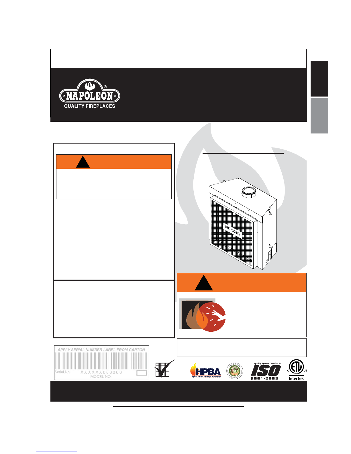
INSTALLATION AND
OPERATING INSTRUCTIONS
Wolf Steel Ltd., 24 Napoleon Rd., Barrie, ON, L4M 0G8 Canada /
103 Miller Drive, Crittenden, Kentucky, USA, 41030
Phone (705)721-1212 Fax (705)722-6031 www.napoleonÞ replaces.com ask@napoleonproducts.com
1.28E
$10.00
HOT GLASS WILL CAUSE
BURNS.
DO NOT TOUCH GLASS UNTIL
COOLED.
NEVER ALLOW CHILDREN TO
TOUCH GLASS.
!
WARNING
ß ¾¿®®·»® ¼»-·¹²»¼ ¬± ®»¼«½» ¬¸» ®·-µ ±º ¾«®²- º®±³ ¬¸»
¸±¬ ª·»©·²¹ ¹´¿-- ·- °®±ª·¼»¼ ©·¬¸ ¬¸» ¿°°´·¿²½» ¿²¼
-¸¿´´ ¾» ·²-¬¿´´»¼ò
SAFETY INFORMATION
!
WARNING
- Do not store or use gasoline or other ß ammable
vapors and liquids in the vicinity of this or any
other appliance.
- WHAT TO DO IF YOU SMELL GAS:
Do not try to light any appliance.
Do not touch any electrical switch; do not use
any phone in your building.
Immediately call your gas supplier from a
neighbours phone. Follow the gas suppliers
instructions.
If you cannot reach your gas supplier, call the
Þ re department.
- Installation and service must be performed by a
qualiÞ ed installer, service agency or the supplier.
This appliance may be installed in an aftermarket,
permanently located, manufactured home (USA
only) or mobile home, where not prohibited by
local codes.
This appliance is only for use with the type of gas
indicated on the rating plate. This appliance is
not convertible for use with other gases, unless a
certiÞ ed kit is used.
If the information in these instructions
are not followed exactly, a Þ re or
explosion may result causing property
damage, personal injury or loss of life.
CERTIFIED FOR CANADA AND UNITED STATES USING ANSI/CSA METHODS.
Decorative Product: Not for use as a heating appliance.
ЮЯООЧЫО
HDX52NT
NATURAL GAS
HDX52PT
PROPANE
CERTIFIED UNDER CANADIAN AND AMERICAN NATIONAL STANDARDS: ANSI Z21.50, CSA 2.22 FOR VENTED GAS FIREPLACES.
Page 2

2
W415-1276 / A / 05.09.14
EN
NOTE: Changes, other than editorial, are denoted by a vertical line in the margin.
TABLE OF CONTENTS
1.0 INSTALLATION OVERVIEW 3
2.0 INTRODUCTION 4
2.1 DIMENSIONS 5
2.2 GENERAL INSTRUCTIONS 5
2.3 GENERAL INFORMATION 6
2.4 RATING PLATE INFORMATION 7
3.0 VENTING 8
3.1 VENTING LENGTHS AND COMPONENTS 8
3.2 TYPICAL VENT INSTALLATION 9
3.3 VENT TERMINAL CLEARANCES 10
3.4 VENT APPLICATION FLOW CHART 11
3.5 DEFINITIONS 11
3.6 ELBOW VENT LENGTH VALUES 11
3.7 HORIZONTAL TERMINATION 12
3.8 VERTICAL TERMINATION 14
4.0 INSTALLATION 16
4.1 WALL AND CEILING PROTECTION 16
4.1.1 HORIZONTAL INSTALLATION 17
4.1.2 VERTICAL INSTALLATION 17
4.2 USING FLEXIBLE VENT COMPONENTS 18
4.2.1 HORIZONTAL AIR TERMINAL INSTALLATION 18
4.2.2 VERTICAL AIR TERMINAL INSTALLATION 19
4.2.3 APPLIANCE VENT CONNECTION 20
4.3 MOBILE HOME INSTALLATION 20
4.4 GAS INSTALLATION 21
5.0 FRAMING 22
5.1 INSTALLING NON-COMBUSTIBLE BOARD 25
5.2 MINIMUM CLEARANCE TO COMBUSTIBLE ENCLOSURES 27
5.3 MINIMUM COMBUSTIBLE MANTEL CLEARANCES 29
6.0 FINISHING 30
6.1 SCREEN DOOR REMOVAL / INSTALLATION 30
6.2 LATCH DOOR REMOVAL / INSTALLATION 31
6.3 GLASS DOOR REMOVAL / INSTALLATION 32
6.4 BURNER INSTALLATION 33
6.5 NON-COMBUSTIBLE FACING MATERIAL 33
6.6 LOGO PLACEMENT 33
7.0 ELECTRICAL INFORMATION 34
7.1 HARD WIRING CONNECTION 34
7.2 RECEPTACLE WIRING DIAGRAM 34
7.3 BATTERY HOLDER INSTALLATION 35
7.4 WIRING DIAGRAM 36
8.0 OPERATION 37
8.1 GENERAL TRANSMITTER LAYOUT 37
8.2 INITIALIZING THE TRANSMITTER/BATTERY HOLDER FOR THE FIRST TIME 37
8.3 TEMPERATURE DISPLAY 38
8.4 FLAME HEIGHT 38
8.5 NIGHT LIGHT DIMMER CONTROL 38
8.6 CONTINUOUS PILOT / INTERMITTENT PILOT (CPI / IPI) SELECTION 39
8.7 KEY LOCK 39
8.8 LOW BATTERY / MANUAL BYPASS 39
9.0 OPERATING INSTRUCTIONS 40
9.1 RESTRICTING VERTICAL VENTS 41
9.2 PILOT BURNER ADJUSTMENT 41
9.3 VENTURI ADJUSTMENT 42
9.4 FLAME CHARACTERISTICS 42
10.0 MAINTENANCE 43
10.1 ANNUAL MAINTENANCE 43
10.2 CONTROL ACCESS 44
10.3 BURNER REMOVAL 45
10.4 BRICK PANEL REMOVAL 45
10.5 PORCELAIN PANEL REMOVAL 45
10.6 MEDIA TRAY REMOVAL (GLASS ONLY) 45
10.7 NIGHT LIGHT REPLACEMENT 46
10.8 GLASS / DOOR REPLACEMENT 47
10.9 CARE OF GLASS 47
10.10 CARE OF PLATED PARTS 47
11.0 REPLACEMENTS 48
12.0 OVERVIEW 49
13.0 ACCESSORIES 50
14.0 LOG BURNER 52
The camera icon indicates video tutorials are available as additional reference,
visit http://www.napoleonÞ replaces.com/category/product-support/support-centre/
Page 3
3
W415-1276 / A / 05.09.14
EN
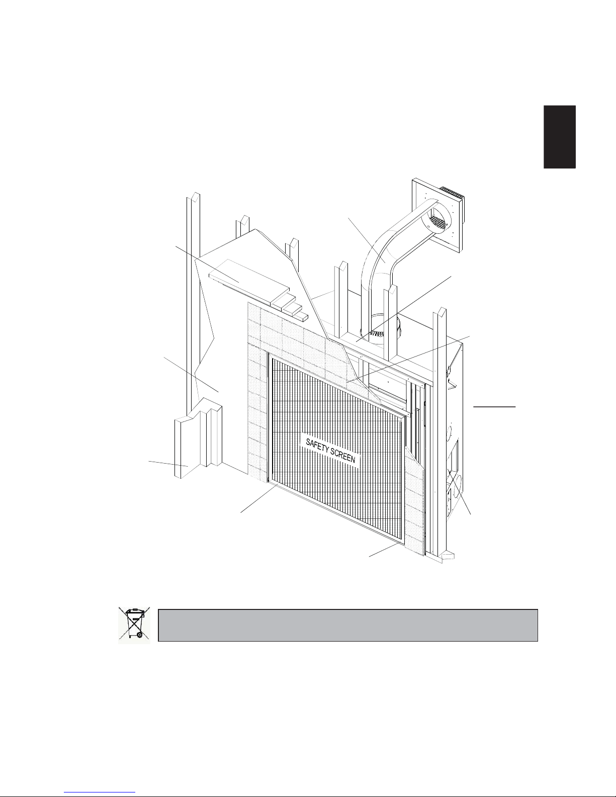
1.0 INSTALLATION OVERVIEW
See the section
“FRAMING MINIMUM MANTEL
CLEARANCES”
See the section
“FRAMING - MINIMUM
CLEARANCE TO
COMBUSTIBLE
ENCLOSURES” for
drywall (or other
combustible material)”
See the section
“FRAMING”
Side
Wall
See the section
“VENTING - VENTING
LENGTHS AND AIR TERMINAL
LOCATIONS”
See the section
“FRAMING”
See the section
“FRAMING - MINIMUM
CLEARANCE TO
COMBUSTIBLE
ENSLOSURES” for
non-combustible
materials such as tile,
marble, granite, etc.
IMPORTANT: Extra
support may be
required.
See the section
“CONTROL ACCESS”
for the control box.
See the section
“BATTERY HOLDER”
See the section
“BURNER INSTALLATION”
Batteries must be disposed of according to the local laws and regulations. Some batteries may be recycled,
and may be accepted for disposal at your local recycling center. Check with your municipality for recycling
instructions.
15.0 ROCK BURNER 53
16.0 TROUBLESHOOTING 56
17.0 WARRANTY 59
Page 4

4
W415-1276 / A / 05.09.14
EN
3.2C
!
WARNING
THIS APPLIANCE IS HOT WHEN OPERATED AND CAN CAUSE SEVERE BURNS IF CONTACTED.
ANY CHANGES OR ALTERATIONS TO THIS APPLIANCE OR ITS CONTROLS CAN BE DANGEROUS AND
IS PROHIBITED.
Do not operate appliance before reading and understanding operating instructions. Failure to operate appliance
according to operating instructions could cause Þ re or injury.
Risk of Þ re or asphyxiation do not operate appliance with Þ xed glass removed.
Do not connect 110 volts to the control valve.
Risk of burns. The appliance should be turned off and cooled before servicing.
Do not install damaged, incomplete or substitute components.
Risk of cuts and abrasions. Wear protective gloves and safety glasses during installation. Sheet metal edges may
be sharp.
Do not burn wood or other materials in this appliance.
Children and adults should be alerted to the hazards of high surface temperature and should stay away to avoid
burns or clothing ignition.
Young children should be carefully supervised when they are in the same room as the appliance. Toddlers, young
children and others may be susceptible to accidental contact burns. A physical barrier is recommended if there
are at risk individuals in the house. To restrict access to an appliance, install an adjustable safety gate to keep
toddlers, young children and other at risk individuals out of the room and away from hot surfaces.
Clothing or other ß ammable material should not be placed on or near the appliance.
Due to high temperatures, the appliance should be located out of trafÞ c and away from furniture and draperies.
Ensure you have incorporated adequate safety measure to protect infants/toddlers from touching hot surfaces.
Even after the appliance is out, the glass and/or screen will remain hot for an extended period of time.
Check with your local hearth specialty dealer for safety screens and hearth guards to protect children from hot
surfaces. These screens and guards must be fastened to the ß oor.
Any safety screen, guard or barrier removed for servicing the appliance, must be replaced prior to operating the
appliance.
The appliance is a vented gas-Þ red appliance. Do not burn wood or other materials in the appliance
It is imperative that the control compartments, burners and circulating blower and its passageway in the appliance
and venting system are kept clean. The appliance and its venting system should be inspected before use and at
least annually by a qualiÞ ed service person. More frequent cleaning may be required due to excessive lint from
carpeting, bedding material, etc. The appliance area must be kept clear and free from combustible materials,
gasoline and other ß ammable vapors and liquids.
Under no circumstances should this appliance be modiÞ ed.
This appliance must not be connected to a chimney ß ue pipe serving a separate solid fuel burning appliance.
Do not use this appliance if any part has been under water. Immediately call a qualiÞ ed service technician to
inspect the appliance and to replace any part of the control system and any gas control which has been under
water.
Do not operate the appliance with the glass door removed, cracked or broken. Replacement of the glass should
be done by a licensed or qualiÞ ed service person.
Do not strike or slam shut the appliance glass door.
When equipped with pressure relief doors, they must be kept closed while the appliance is operating to prevent
exhaust fumes containing carbon monoxide, from entering into the home. Temperatures of the exhaust escaping
through these openings can also cause the surrounding combustible materials to overheat and catch Þ re.
Only doors / optional fronts certiÞ ed with the appliance are to be installed on the appliance.
Keep the packaging material out of reach of children and dispose of the material in a safe manner. As with all
plastic bags, these are not toys and should be kept away from children and infants.
As with any combustion appliance, we recommend having your appliance regularly inspected and serviced as
well as having a Carbon Monoxide Detector installed in the same area to defend you and your family against
Carbon Monoxide.
Ensure clearances to combustibles are maintained when building a mantel or shelves above the appliance.
Elevated temperatures on the wall or in the air above the appliance can cause melting, discolouration or damage
of decorations, a T.V. or other electronic components.
A barrier designed to reduce the risk of burns from the hot viewing glass is provided with this appliance and shall
be installed.
If the barrier becomes damaged, the barrier shall be replaced with the manufacturers barrier for this appliance.
Installation and repair should be done by a qualiÞ ed service person. The appliance should be inspected before
use and at least annually by a professional service person. More frequent cleaning may be required due to
excessive lint from carpeting, bedding material, etc. It is imperative that control compartments, burners and
circulating air passageways of the appliance be kept clean.
2.0 INTRODUCTION
Page 5
5
W415-1276 / A / 05.09.14
EN
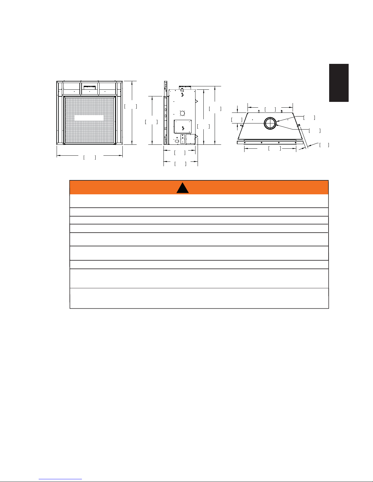
ëê éñèþ
ïììë³³
лм пнспкю
ïíçî³³
ëð íñèþ
ïîèð³³
ìï éñèþ
ïðêì³³
îé ïñèþ
êèç³³
îç ïñèþ
éìð³³
мй пйсною
порй³³
ìì íñìþ
ïïíé³³
îþ
ëï³³
íè éñèþ
çèé³³
H ç éñèþ
îëï³³
H é éñèþ
îðð³³
з нспкю
îíí³³
SAFETY SCREEN
2.1 DIMENSIONS
THIS GAS APPLIANCE SHOULD BE INSTALLED AND SERVICED BY A QUALIFIED INSTALLER to
conform with local codes. Installation practices vary from region to region and it is important to know the
speciÞ cs that apply to your area, for example in Massachusetts State:
This product must be installed by a licensed plumber or gas Þ tter when installed within the commonwealth
of Massachusetts.
The appliance damper must be removed or welded in the open position prior to installation of an appliance
insert or gas log.
The appliance off valve must be a T handle gas cock.
The ß exible connector must not be longer than 36 inches (914mm).
A Carbon Monoxide detector is required in all rooms containing gas Þ red appliances.
The appliance is not approved for installation in a bedroom or bathroom unles s the unit is a direct vent
sealed combustion product.
ALWAYS LIGHT THE PILOT WHETHER FOR THE FIRST TIME OR IF THE GAS SUPPLY HAS RUN OUT,
WITH THE GLASS DOOR OPENED OR REMOVED.
PROVIDE ADEQUATE CLEARANCE FOR SERVICING AND OPERATING THE APPLIANCE.
PROVIDE ADEQUATE VENTILATION.
NEVER OBSTRUCT THE FRONT OPENING OF THE APPLIANCE.
OBJECTS PLACED IN FRONT OF THE APPLIANCE MUST BE KEPT A MINIMUM OF 48” (1219mm) FROM
THE FRONT FACE OF THE APPLIANCE.
SURFACES AROUND AND ESPECIALLY ABOVE THE APPLIANCE CAN BECOME HOT. AVOID CONTACT
WHEN THE APPLIANCE IS OPERATING.
FIRE RISK. EXPLOSION HAZARD.
HIGH PRESSURE WILL DAMAGE VALVE. DISCONNECT GAS SUPPLY PIPING BEFORE PRESSURE TESTING GAS
LINE AT TEST PRESSURES ABOVE 1/2 PSIG. CLOSE THE MANUAL SHUT-OFF VALVE BEFORE PRESSURE
TESTING GAS LINE AT TEST PRESSURES EQUAL TO OR LESS THAN 1/2 PSIG (35 mb).
USE ONLY WOLF STEEL APPROVED OPTIONAL ACCESSORIES AND REPLACEMENT PARTS WITH THIS APPLIANCE.
USING NON-LISTED ACCESSORIES (BLOWERS, DOORS, LOUVRES, TRIMS, GAS COMPONENTS, VENTING
COMPONENTS, ETC.) COULD RESULT IN A SAFETY HAZARD AND WILL VOID THE WARRANTY AND CERTIFICATION.
!
WARNING
2.2 GENERAL INSTRUCTIONS
Page 6
6
W415-1276 / A / 05.09.14
EN
This appliance is approved for bathroom, bedroom and bed-sitting room installations and is certiÞ ed for mobile
home installation.
This appliance is only for use with the type of gas indicated on the rating plate. This appliance is not
convertible for use with other gases, unless a certiÞ ed kit is used.
When the appliance is installed at elevations above 4,500ft (1371m), and in the absence of speciÞ c
recommendations from the local authority having jurisdiction, the certiÞ ed high altitude input rating shall be
reduced at the rate of 4% for each additional 1,000ft (305m).
Expansion / contraction noises during heating up and cooling down cycles are normal and are to be expected.
Change in ß ame appearance from HI to LO is more evident in natural gas than in propane.
2.3 GENERAL INFORMATION
4.1B
The installation must conform with local codes or, in
absence of local codes, the National Gas and Propane
Installation Code CSA B149.1 in Canada, or the National
Fuel Gas Code, ANSI Z223.1 / NFPA 54 in the United
States. Suitable for mobile home installation if installed in
accordance with the current standard CAN/CSA Z240MH
Series, for gas equipped mobile homes, in Canada or
ANSI Z223.1 and NFPA 54 in the United States.
As long as the required clearance to combustibles is
maintained, the most desirable and beneÞ cial location
for an appliance is in the center of a building, thereby
allowing the most efÞ cient use of the heat created. The location of windows, doors and the trafÞ c ß ow in the
room where the appliance is to be located should be considered. If possible, you should choose a location
where the vent will pass through the house without cutting a ß oor or roof joist.
If the appliance is installed directly on carpeting, vinyl tile or other combustible material other than wood
ß ooring, the appliance shall be installed on a metal or wood panel extending the full width and depth.
Some appliances have optional fans or blowers. If an optional fan or blower is installed, the junction box must
be electrically connected and grounded in accordance with local codes, use the current CSA C22.1 Canadian
Electrical Code in Canada or the ANSI/NFPA 70 National Electrical code in the United States.
É» -«¹¹»-¬ ¬¸¿¬ ±«® ¹¿¸»¿®¬¸ °®±¼«½¬- ¾» ·²-¬¿´´»¼
¿²¼ -»®ª·½»¼ ¾§ °®±º»--·±²¿´-
¾§ ¬¸» Т¿¬·±²¿´ Ъ·®»°´¿½»
Ч²-¬·¬«¬»r шТЪЧч ¿- ТЪЧ Щ¿Н°»½·¿´·-¬-
FOR YOUR SATISFACTION, THIS APPLIANCE HAS BEEN TEST-FIRED TO ASSURE ITS OPERATION AND
QUALITY!
HDX52
NG LP
Altitude (FT) 0-4,500 0-4500
Max. Input (BTU/HR) 55,000 55,000
Max. Output Steady State (BTU/HR) 37,391 36,500
EfÞ ciency (w/the fan on) 64% 68%
Min. Inlet Gas Supply Pressure 4.5" w.c. (11mb) 11" w.c. (27mb)
Max. Inlet Gas Supply Pressure 7" w.c. (17mb) 13" w.c. (32mb)
Manifold Pressure (Under Flow Conditions) 3.5" w.c. (9mb) 10" w.c. (25mb)
Page 7
7
W415-1276 / A / 05.09.14
EN
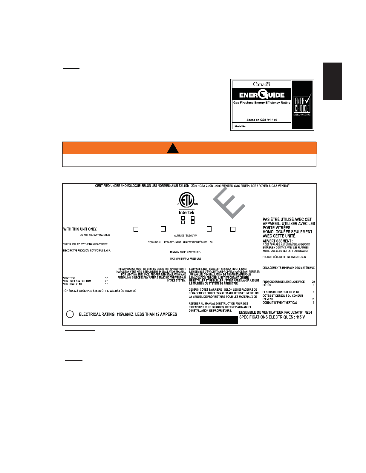
2.4 RATING PLATE INFORMATION
NOTE: The protective wrap on plated parts is best removed when the assembly is at room temperature
but this can be improved if the assembly is warmed, using a hair dryer or similar heat source.
This appliance is equipped with a remote control system, which
requires batteries (supplied) to be installed. The transmitter takes 1
9V battery and in the case of a power failure the receiver takes 4 AA
batteries.
INSTALLER: It is your responsibility to check off the appropriate box on the rating plate according to
the model, venting and gas type of the appliance.
The illustration is for reference only. Refer to the rating plate on the appliance for accurate information.
NOTE: The rating plate must remain with the appliance at all times. It must not be removed.
êëû
HDX52
Both the rating plate and lighting instructions are attached to a cable and inserted along the left side of the appliance.
!
WARNING
ALLOW APPLIANCE TO COOL BEFORE PERFORMING ANY MAINTANCE OR CLEANING.
W385-1928
CHDX52N CHDX52P
NOT FOR USE WITH SOLID
FUEL. FOR USE WITH
GLASS DOORS CERTIFIED
WARNING:
TO THE APPLIANCE, WHICH WILL COME IN
CONTACT WITH THE FL AMES, OTHER THAN
WITH THE APPLIAN CE
HEATING APPLIANCE.
MINIMUM CLEARANCE TO
COMBUSTIBLE MATERIALS:
TOP 0"
FLOOR 0"
RECESSED DEPTH 29"
SIDES 0"
BACK 0"
MANTEL 6"*
MATERIALS. FOR FINISHING MATERIALS SEE OWNER’S MANUAL
*MAXIMUM HORIZONTAL EXTENSION 2". SEE INSTRUCTION MANUAL FOR GREATER
EXTENSIONS. SEE OWNER’S INSTRUCTION MANUAL FOR MINIMUM AND
MAXIMUM LENGTHS.
WOLF STEEL LTD.
24 NAPOLEON ROAD, BARRIE, ON, L4M 0G8 CANADA
60HZ. MOINS DE 12 AMPÈRES.
HDX52N HDX52P
MODEL PROPANE /
PROPANE MODÈLE
UN COMBUSTIBLE SOLIDE NE
N’AJOUTEZ PAS
CET APPAREIL PAR LE FABRICANT.
COMME APPAREIL DE CHAU FFAGE
COMBUSTIBLES :
DESSUS 0"
PLANCHER 0"
"
"
ARRIÈRE 0"
"
"
"
TABLETTE 6"*
FINITION. *L’EXTENSION HORIZONTALE MAXIMALE : 2".
MODEL NATURAL GAS /
GAZ NATURAL
0-4500FT (0-1370M) 0-4500FT (0-1370M)
55,000 BTU/H INPUT / ALIMENTATION 55,000 B TU/H
,500 BTU/H
3.5" WATER COLUMN/D’UNE COLONN E D’EAU MANIFOLD PRESSURE / 10" WATER COLUMN/D’UNE COLONNE D’EAU
PRESSION AU COLLECTE UR
4.5" WATER COLUMN/D’UNE COLONNE D’EAU 11" WATER COLUMN/D’UNE COLONNE D’EAU
PRESSION D’ALIMENTATION MINIMALE
7.0" WATER COLUMN/D’UNE COLONNE D’EAU 13" WATER COLUMN/D’UNE COLONN E D’EAU
PRESSION D’ALIMENTATION MAXIMALE
65.2% P.4 FE 65.2%
SERIAL NUMBER/ NO. DE SÉRIE: HDX52
THIS APPLIANCE MUST BE INSTALLED IN ACCORDANCE WITH LOCAL CODES, IF ANY; IF NONE, FOLLOW THE
CURRENT ANSI Z223.1 OR CSA B149, INSTALLATION COD ES. VENTED GAS FIREPLACE. APPROVED FOR
BEDROOM, BATHROOM AND BED-SITTING ROOM INSTALLATION. SUITABLE FOR MOBILE HOME
INSTALLATION IF INSTALLED IN ACCORDANCE WITH THE CU RRENT STANDARD CA N/CSA Z240MH SERIES
GAS EQUIPPED MOBILE HOMES, IN CANADA OR IN THE UNITED STATES THE MANUFACTURED HOME
CONSTRUCTION AND SAFETY STANDARD, TITLE 24 CFR, PART 3280. WHEN THIS US STANDARD IS NOT
APPLICABLE USE THE STANDARD FOR FIRE SAFETY CRITERIA FOR MANUFACTURED HOME INSTALLATIONS, SITES AND COMMUNITIES, ANSI/NFPA 501A
INSTALLER L’APPAREIL SELON LES CODE S D’INSTALLATION ANSI Z223.1 OU CSA -B149 EN VIGUER.
FOYER À GAZ VENTILÉ. HOMOLOGUÉ POUR INSTALLATION DAN S UNE CHAMBRE À COUCHER, UNE SALLE DE
BAIN ET UN STUDIO. APPROPRIÉ POUR INSTALLATION DANS UNE MAISON MOBILE SI SON INSTALLATION
CONFORME AUX EXIGENCES DE LA NORME CAN/CSA Z240MH SÉRI E DE MAISONS MOBILES ÉQUIPÉES AU
GAZ EN VIGEUR AU CANADA OU AUX ÉTATS-UNIS DE LA NORME DE SECURITE ET DE CONSTRUCTION DE
MAISONS MANUFACTUREE, TITRE 24 CFR, SECTION 3280. DANS LE CAS OU CETTE NORME D’ÉTATS-UNIS N E
PEUT ETRE APPLIQUÉE, SE REFERER A LA NORME RELATIVE AU CRITÈRE DE MESURES DE SÉCUR ITÉ
CONTRE L’INCENDIE POUR LES INSTALLATIONS DANS LES MAISONS MAN UFACTURÉS, LES SITE S ET LES
COMMUNAUTÉS, ANSI/NFPA 501A.
9700539 (WSL)
4001658 (NAC)
4001657 (NGZ)
4001659 (WUSA)
OPTIONAL FAN KIT: NZ64
Page 8

8
W415-1276 / A / 05.09.14
EN
3.0 VENTING
3.1 VENTING LENGTHS AND COMPONENTS
This Þ replaces uses 8 (203.2mm) exhaust / 10 (254mm) air intake vent pipe system.
Refer to the section applicable to your installation.
For safe and proper operation of the Þ replace follow the venting instruction exactly. Deviation from the minimum
vertical vent length can create difÞ culty in burner start-up and/or carboning. Under extreme vent conÞ gurations,
allow several minutes (5-15) for the ß ame to stabilize after ignition. Provide a means for visually checking the vent
connection to the Þ replace after the Þ replace is installed. Use a Þ restop, vent pipe shield or attic insulation shield
when penetrating interior walls, ß oor or ceiling.
NOTE: If for any reason the vent air intake system is disassembled; reinstall per the instructions provided
for the initial installation.
7.3B
!
WARNING
RISK OF FIRE, MAINTAIN SPECIFIED AIR SPACE CLEARANCES TO VENT PIPE AND APPLIANCE.
IF VENTING IS INCLUDED WITH SPACERS THE VENT SYSTEM MUST BE SUPPORTED EVERY 3FT
(0.9m) FOR BOTH VERTICAL AND HORIZONTAL RUNS. USE SUPPORTS OR EQUIVALENT
NON-COMBUSTIBLE STRAPPING TO MAINTAIN THE REQUIRED CLEARANCE FROM
COMBUSTIBLES. USE WOLF STEEL LTD. SUPPORT RING ASSEMBLY W010-0370 OR EQUIVALENT
NON-COMBUSTIBLE STRAPPING TO MAINTAIN THE MINIMUM CLEARANCE TO COMBUSTIBLES
FOR BOTH VERTICAL AND HORIZONTAL RUNS. SPACERS ARE ATTACHED TO THE INNER PIPE AT
PREDETERMINED INTERVALS TO MAINTAIN AN EVEN AIR GAP TO THE OUTER PIPE. THIS GAP IS
REQUIRED FOR SAFE OPERATION. A SPACER IS REQUIRED AT THE START, MIDDLE AND END OF
EACH ELBOW TO ENSURE THIS GAP IS MAINTAINED. THESE SPACERS MUST NOT BE REMOVED.
For vent systems that provide seals on the inner exhaust ß ue, only the outer air intake joints must be sealed
using a red high temperature silicone (RTV). This same sealant may be used on both the inner exhaust and
outer intake vent pipe joints of all other approved vent systems except for the exhaust vent pipe connection to the
Þ replace ß ue collar which must be sealed using the black high temperature sealant Mill Pac.
When using Wolf Steel venting components, use only approved Wolf Steel ß exible components with the
following termination kits: wall terminal kit GD622R, or 1/12 to 7/12 pitch roof terminal kit GD610, 8/12 to 12/12
roof terminal kit GD611 or ß at roof terminal kit GD612. With ß exible venting, in conjunction with the various
terminations, use either the 5 foot (1.5m) vent kit GD620 or the 10 foot (3m) vent kit GD630.
For optimum ß ame appearance and Þ replace performance, keep the vent length and number of elbows to
a minimum.
The air terminal must remain unobstructed at all times. Examine the air terminal at least once a year to
verify that it is unobstructed and undamaged.
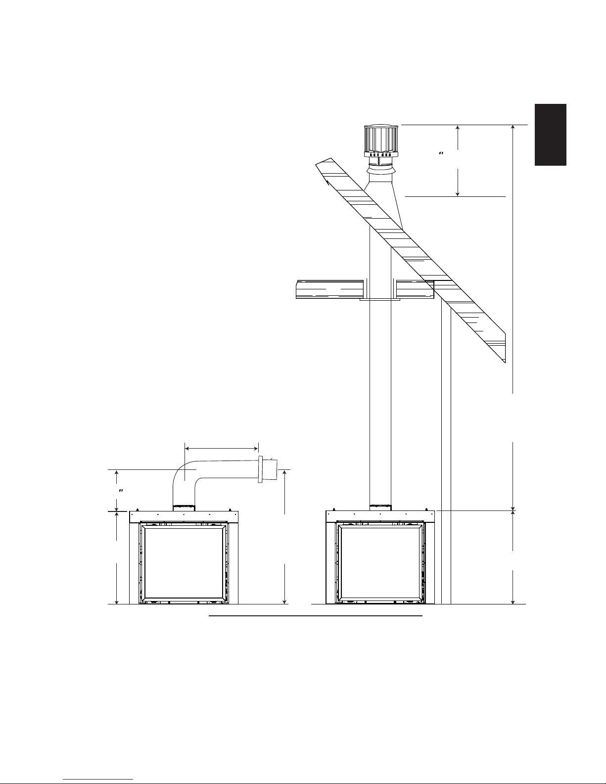
The minimum allowable vertical vent length is 3 feet (0.9m) maximum allowable vertical vent length is 40 feet
(12m). The maximum number of allowable 8 (203mm) vent connections is three horizontally or vertically
(excluding the Þ replace and the air terminal connections).
When venting, the horizontal run must be kept to a minimum of 36 (914mm) or a maximum of 20 feet (6m).
If a 20 foot (6m) horizontal run is required, the Þ replace must have a minimum vertical rise immediately off
the Þ replace of 57 (1448mm). When terminating vertically, the vertical rise is a minimum 36 (914mm) and a
maximum 40 feet (12m) above the Þ replace.
For optimum performance, it is recommended that all horizontal runs have a minimum 1/4 (6mm) rise
per foot/meter. Provide a means for visually checking the vent connection to the Þ replace after the
Þ replace is installed. Do not allow the inside liner to bunch up on horizontal or vertical runs and elbows.
Keep it pulled tight. A 3/4 (19mm) air gap between the inner and outer liner all around is required for saf
e
operation. Use a Þ restop when penetrating interior walls, ß oor or ceiling.
8.4A
18" (457mm)
Page 9
9
W415-1276 / A / 05.09.14
EN
45.8
18" (457mm)
MAXIMUM
24 (610mm)
MIN.
71 1/2"
(1816mm)
PLUS RISE *
16 (406mm)
MINIMUM
40 FEET
(12m)
MAXIMUM
3 FEET (0.9m)
MINIMUM
47 1/2"
(1207mm)
3.2 TYPICAL VENT INSTALLATION
Refer to VENTING section.
47 1/2"
(1207mm)
Page 10
10
W415-1276 / A / 05.09.14
EN
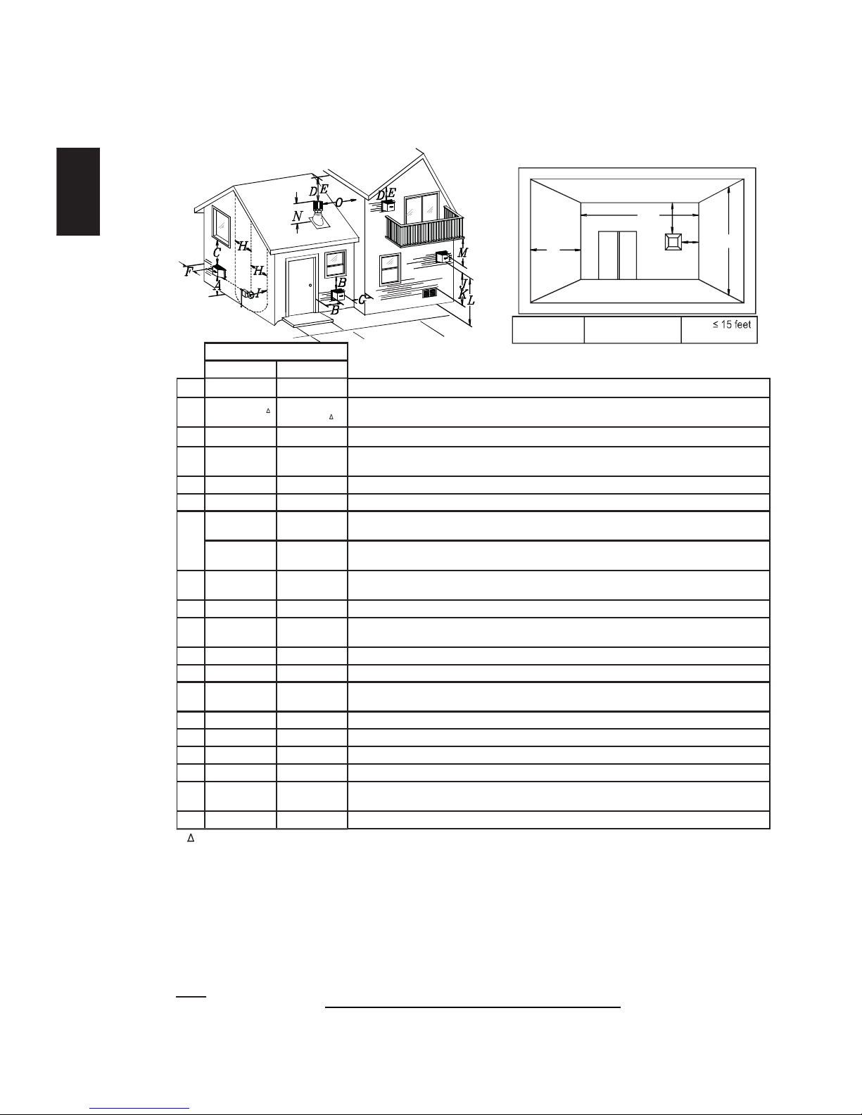
3.3 VENT TERMINAL CLEARANCES
INSTALLATIONS
CANADA U.S.A.
A
12 (305mm) 12 (305mm) Clearance ab ove grade , veranda porch, deck or balcony.
B
12 (305mm)
9
(229mm)
Clearance to windows or doors that open.
C
12 (305mm)* 12 (305mm) * Clearance to permane ntly closed windows.
D
18
(457mm)**
18 (457mm)**
Vertical clearance to ventilated sofÞ ts located a bove the terminal wit hin a horizon tal distance of 2
(0.6m) from the center line of the terminal.
E
12 (305mm)** 12 (305mm)** Clearance to unventilated so fÞ t.
F
0 (0mm) 0 (0mm) Clearance to an outside corner wall.
G
0 (0mm)***
0
(0mm)***
Clearance to an inside
non
-combustible corner wall or protruding
non
-combustible obstructions (chimney,
etc.).
2 (51mm)* **
2
(51mm)***
Clearance to an inside combustible corner wall or protruding combustible obstructions (vent chase,
etc.).
H
3(0.9m) 3 (0.9m)****
Clearance to each side of the center line extended above the meter / regulator assembly to a
maximum v ertical distance of 15 (4 .6m).
I
3 (0.9m) 3 (0.9m)* *** Clearance to a se rvice regulator vent outlet.
J
12 (305mm) 9 (229mm)
Clearance to a non-mechanical air supply inlet to the building or a combustion air inlet to any other
appliance.
K
6 (1.8m) 3 (0.9m) Clearance to a mechan ical air supply inlet.
L
7 (2.1m) 7 (2.1 m) **** Clearance above a paved sidewalk or paved driveway located on public property.
M
12
(305mm)
12
(305mm)****
Clearance under a veranda, porch or deck.
N
16 (406mm) 16 (406mm) Clearance ab ove the roof.
O
2 (0.6m)* 2 (0.6m) * Clearance fro m an adja cent wall including ne ighbouring buildings.
P
8 (2.4m) 8(2.4m) Roof must be
non
-combustible without openings.
Q
3 (0.9m) 3 (0.9m) See chart for wider wall dimension s.
R
6 (1.8m) 6 (1.8m)
See chart for deeper wall dimensions. The terminal shall not be installed on any wall that has an
opening between the terminal and the open side of the structure.
S
12 (305mm) 12 (305mm) Clearance un der a covered balcon y
The terminal shall not be located less than 6 feet under a window that opens on a horizontal plane in a structure with three walls and a roof.
* Recommended to prevent condensation on windows and thermal breakage
** It is recommended to use a heat shield and to maximize the distance to vinyl clad sofÞ ts.
*** The periscope requires a minimum 18 inches clearance from an inside corner.
**** This is a recommended distance. For additional requirements check local codes.
3 feet above if with in 10 feet horizontally.
A vent shall not terminate where it may cause hazardous f rost or ice accumulations on adjacent property surfaces.
Permitted only if the ver anda, porch, or deck is f ully open on a minimum of two sides beneath the ß oor.
* Recomme nded to prevent recir culation of exhaust pro ducts. For additional requ irements check local code s.
* Permitted on ly if the balcony is fully op en on a minimum of one side.
12.1D
NOTE: Clearances are in accordance with local installation codes and the requirements of the gas supplier.
COVERED BALCONY APPLICATIONS
*
Q
MIN
R
MAX
MAX
R
= 3 feet
(0.9m)
= 2 x
(4.6m)
Q
ACTUAL
R
Q
S
G
P
Page 11
11
W415-1276 / A / 05.09.14
EN
13.1A
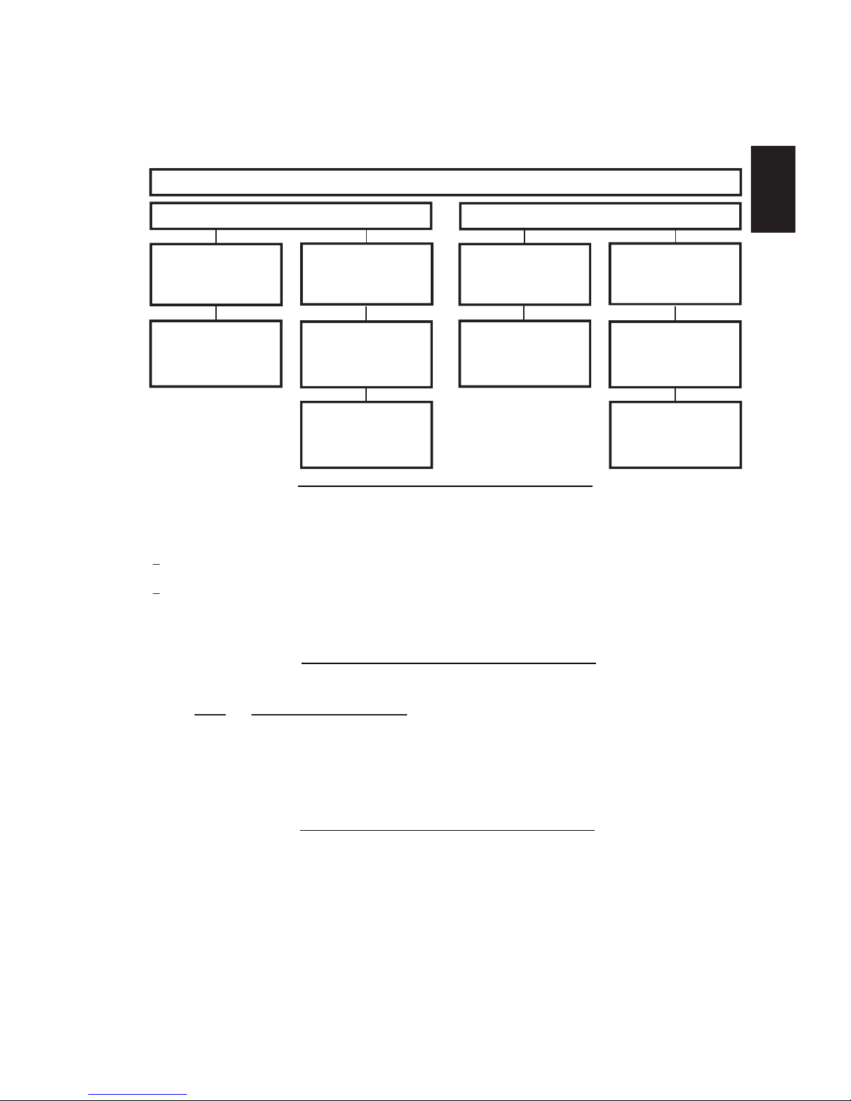
TOP EXIT
Horizontal Termination
Vertical Termination
Vertical rise is equal
to or greater than
the horizontal run
Vertical rise is less
than horizontal run
Vertical rise is equal
to or greater than
the horizontal run
Vertical rise is less
than horizontal run
Horizontal run +
vertical rise to
maximum of 40 feet
(12m)
Horizontal run +
vertical rise to
maximum of
24.75 feet (7.5m)
Horizontal run +
vertical rise to
Horizontal run +
vertical rise to
4.2 times the
vertical rise equal to
or greater than the
horizontal run
3 times the vertical
rise equal to or
greater than the
horizontal run
maximum of 40 feet
(12m)
maximum of 40 feet
(12m)
14.1
For the following symbols used in the venting calculations and examples are:
> - greater than
> - equal to or greater than
< - less than
< - equal to or less than
HT - total of both horizontal vent lengths (Hr) and offsets (Ho) in feet
HR - combined horizontal vent lengths in feet
HO - offset factor: .03 (total degrees of offset - 90°*) in feet
VT - combined vertical vent lengths in feet
15.1A
FEET INCHES MILLIMETERS
1° 0.03 0.5 12.7
15° 0.45 6.0 152.4
30° 0.9 11.0 279.4
45° 1.35 16.0 406.4
90°* 2.7 32.0 812.8
* The Þ rst 90° offset has a zero value and is shown in the formula as - 90°
3.4 VENT APPLICATION FLOW CHART
3.5 DEFINITIONS
3.6 ELBOW VENT LENGTH VALUES
Page 12
12
W415-1276 / A / 05.09.14
EN
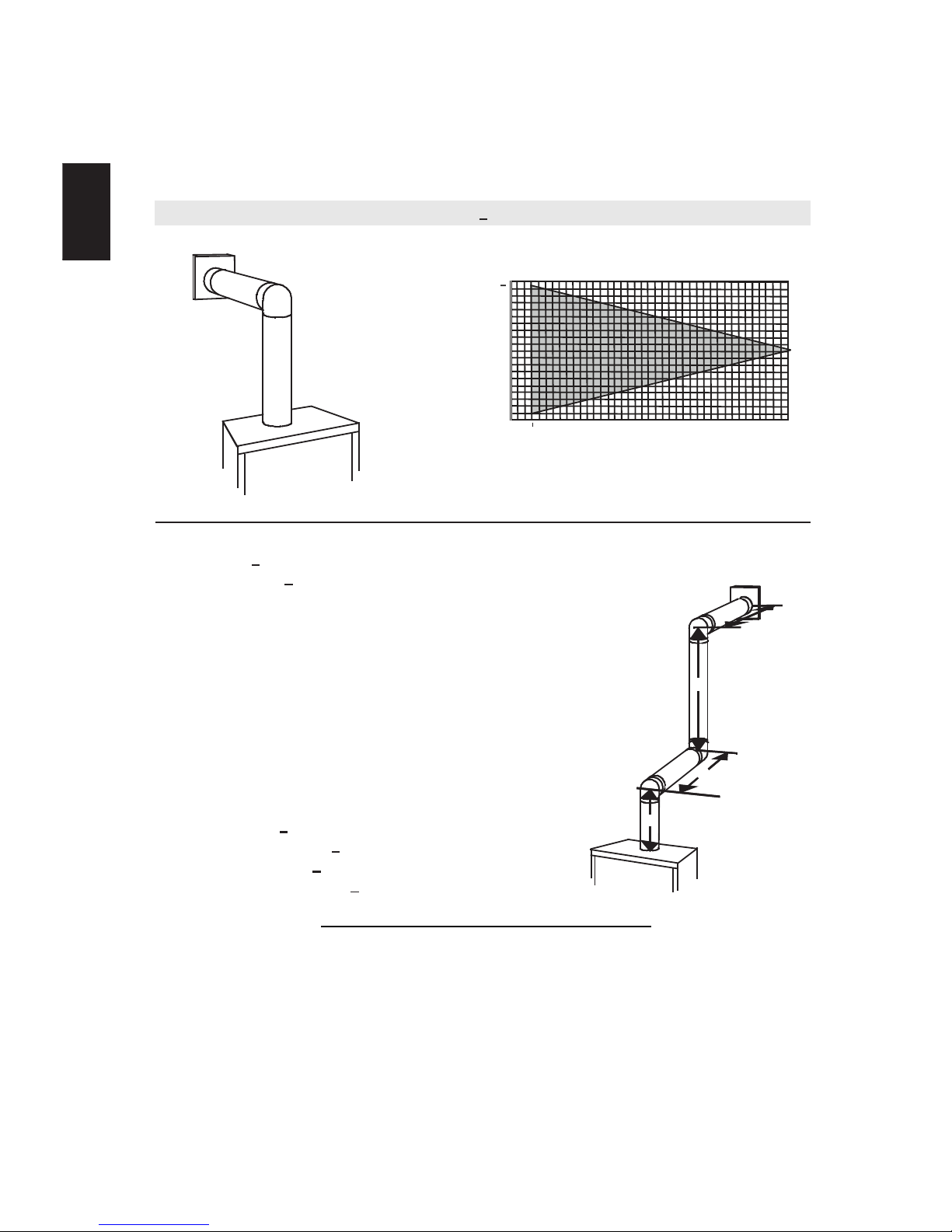
16.1B
Simple venting conÞ guration (only one 90° elbow)
(HT) < (VT)
For vent conÞ gurations requiring more than one 90° elbow, the following formulas apply:
Formula 1: HT < V
T
Formula 2: HT + VT < 40 feet (12.2m)
Example:
V1 = 3 FT (0.9m)
V2 = 8 FT (2.4m)
VT = V1 + V2= 3 FT (0.9m ) + 8 FT (2.4m) = 11 FT (3.4m)
H1 = 2.5 FT (0.8m)
H2 = 2 FT (0.6m)
HR = H1 + H2 = 2.5 FT (0.8m) + 2 FT (0.6m) = 4.5 FT (1.4m)
HO = .03 (three 90° elbows - 90°) = .03 (270° - 90°) = 5.4 FT (1.7m)
HT = HR + HO = 4.5 FT (1.4m) + 5.4 FT (1.6m) = 9.9 FT (3m)
HT + VT = 9.9 FT (3m) + 11 FT (3.4m) = 20.9 FT (6.4m)
Formula 1: HT < V
T
9.9 FT (3m) < 11 FT (3.4m)
Formula 2: HT + VT < 40 FT (12.2m)
20.9 FT (6.4m) < 40 FT (12.2m)
Since both formulas are met, this vent conÞ guration is acceptable.
See graph to determine the required vertical
rise VT for the required horizontal run HT.
The shaded area within the lines represents
acceptable values for HT and V
T
0
2.5
(0.8)5(1.5)
7.5
(2.3)10(3.1)
12.5
(3.8)15(4.6)
40 (12.2)
10 (3.1)
20 (6.1)
30 (9.1)
17.5
(5.3)20(6.1)
39 (11.9)
REQUIRED
VERTICAL
RISE IN FEET
(METERS)V
T
HORIZONTAL VENT RUN PLUS OFFSET IN
FEET (METERS) H
T
90°
90°
90°
V
1
V
2
H
1
H
2
3.7 HORIZONTAL TERMINATION
2 (0.6)
18"
Page 13
13
W415-1276 / A / 05.09.14
EN
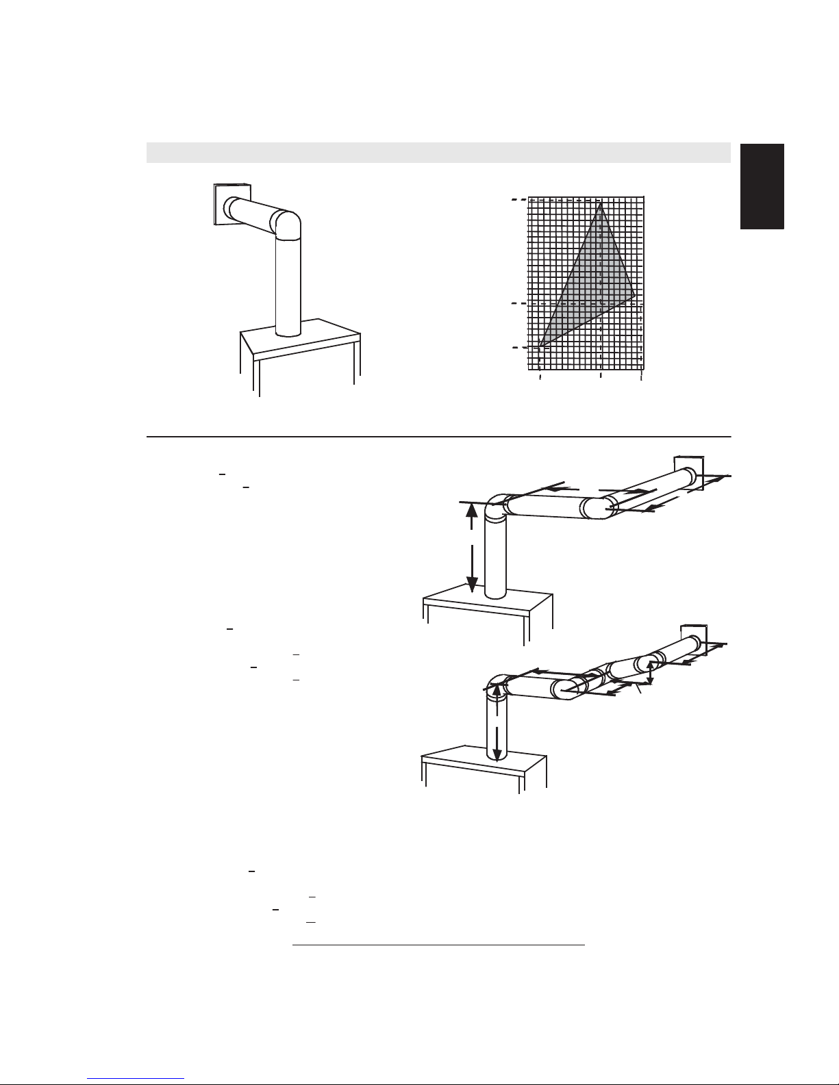
(HT) > (VT)
Simple venting configuration (only one 90° elbow)
See graph to determine the required vertical rise VT for the
required horizontal run HT.
REQUIRED
VERTICAL RISE
IN INCHES
(MILLIMETERS)
V
T
HORIZONTAL VENT RUN PLUS OFFSET IN FEET (METERES) H
T
For vent configurations requiring more than one 90° elbow, the following formulas apply:
Formula 1: HT < 4.2 V
T
Formula 2: HT + VT< 24.75 feet (7.5m)
Example:
V1= VT= 6 FT (1.8m)
H1= 3 FT (0.9m)
H2= 5 FT (1.5m)
HR= H1+ H2= 3FT (0.9m) + 5FT (1.5m) = 8 FT (2.4m)
HO= .03 (two 90° elbows - 90°) = .03 (180° - 90°) = 2.7FT (0.8m)
HT= HR+ HO= 8FT (2.4m) + 2.7FT (0.8m) = 10.7FT (3.3m)
HT+ VT= 10.7FT (3.3m) + 6FT (1.8m) = 16.7FT (5.1m)
Formula 1: HT < 4.2 V
T
4.2 VT= 4.2FT (1.3m) x 6FT (1.8m) = 25.2FT (7.7m)
10.7FT (3.3m) < 25.2FT (7.7m)
Formula 2: HT + VT< 24.75 FT (7.5m)
16.7FT (5.1m) < 24.75 (7.5m)
Since both formulas are met, this vent configuration is acceptable.
0
5
(1.5)
15
(4.6)
20 (6.1)
100 (2540)
50 (1270)
150 (3810)
12.5
(3.8)
19 1/2
(495.3)
57 (1447.8)
147
(3733.8)
2
(0.6)
The shaded area within the lines represents acceptable
values for HTand V
T
90°
V
1
H
1
H
2
90°
Example:
V1= 4 FT (1.2m)
V2= 1.5 FT (0.5m)
VT= V1+ V2= 4FT (1.2m) + 1.5FT (0.5m) = 5.5 FT (1.7m)
H1= 2 FT (0.6m)
H2= 1 FT (0.3m)
H3= 1 FT (0.3m)
H4= 1.5 FT (0.5m)
HR= H1+ H2+ H3+ H4= 2FT (0.6m) + 1FT (0.3m) + 1FT (0.3m) + 1.5FT (0.5m) = 5.5 FT (1.7m)
HO= .03 (four 90° elbows - 90°) = .03 (360° - 90°) = 8.1 FT (2.5m)
HT= HR+ HO= 5.5 FT (1.7m) + 8.1 FT (2.5m) = 13.6 FT (4.2m)
HT+ VT= 13.6 FT (4.2m) + 5.5 FT (1.7m) = 19.1 FT (5.8m)
Formula 1: HT < 4.2 V
T
4.2 VT= 4.2 FT (1.3m) x 5.5 FT(1.7m) = 23.1 FT (7m)
13.6 FT (4.2m) < 23.1 FT (7m)
Formula 2: HT + VT< 24.75 FT (7.5m)
19.1FT (5.8m) < 24.75 FT (7.5m)
Since both formulas are met, this vent configuration is acceptable.
90°
90°
90°
90°
H
1
H
2
V
1
V
2
H
3
H
4
10
(3.1)
19.5
(5.9)
16.1_2A
24 (7.3)
18
(5.5)
Page 14
14
W415-1276 / A / 05.09.14
EN
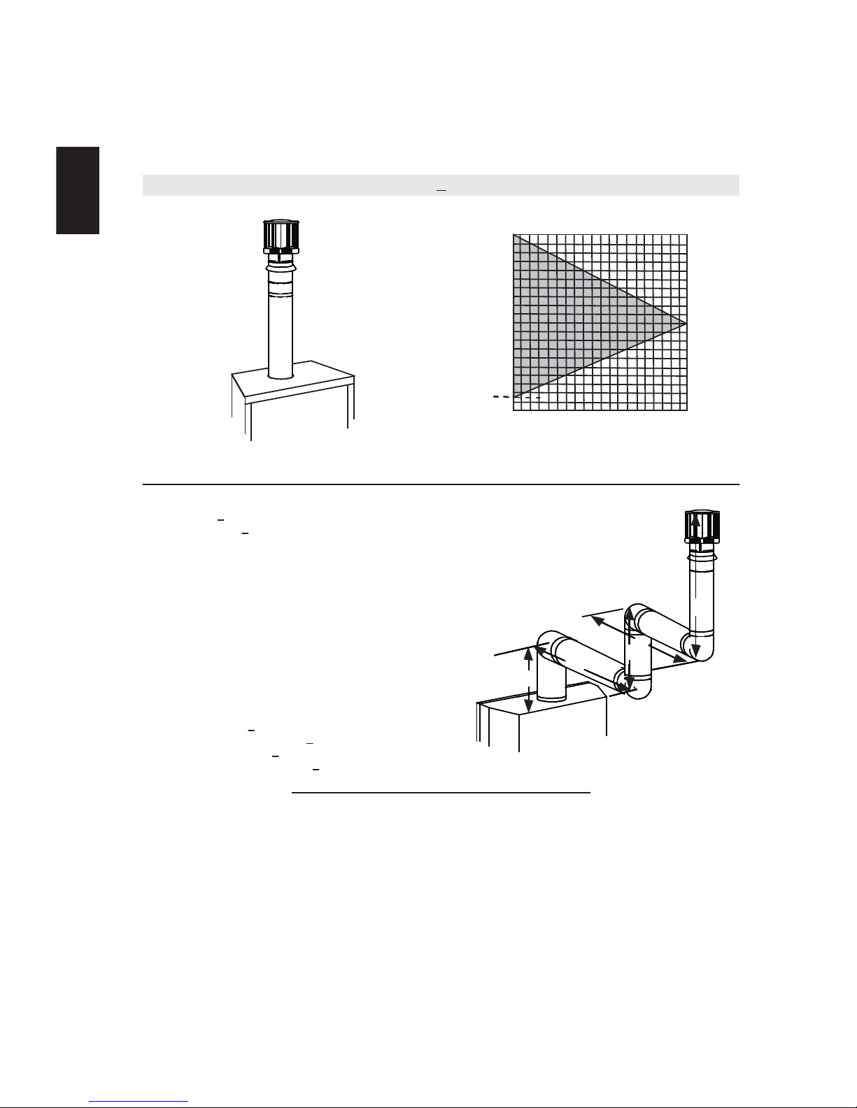
(HT) < (VT)
Simple venting configurations.
See graph to determine the required vertical rise VT for the
required horizontal run HT.
REQUIRED
VERTICAL
RISE IN FEET
(METERS) V
T
HORIZONTAL VENT RUN PLUS OFFSET IN FEET (METERS) H
T
For vent configurations requiring one or more 90° elbows the following formulas apply:
Formula 1: HT < V
T
Formula 2: HT + VT< 40 feet (12.2m)
Example:
V1= 5 FT (1.5m)
V2= 6 FT (1.8m)
V3= 10 FT (3.1m)
VT= V1+ V2+ V3= 5FT (1.5m) + 6FT (1.8m) + 10FT (3.1m) = 21FT (6.4m)
H1= 8 FT (2.4m)
H2= 2.5 FT (0.8m)
HR= H1+ H2= 8FT (2.4m) + 2.5FT (0.8m) = 10.5 FT (3.2m)
HO= .03 (four 90° elbows - 90°)
= .03 (360° - 90°) = 8.1 FT (2.5m)
HT= HR+ HO= 10.5FT (3.2m) + 8.1FT (2.5m) = 18.6FT (5.7m)
HT+ VT= 18.6FT (5.7m) + 21FT (6.4m) = 39.6FT (12.1m)
Formula 1: HT < V
T
18.6FT (5.7m) < 21FT (6.4m)
Formula 2: HT + VT< 40 FT (12.19m)
39.6FT (12.1m) < 40FT (12.2m)
Since both formulas are met, this vent configuration is acceptable.
90°
V
1
V
2
H
1
H
2
The shaded area within the lines represents acceptable
values for HTand V
T
90°
90°
90°
0
5
(1.5)10(3.1)15(4.6)20(6.1)
40 (12.2)
10 (3.1)
20 (6.1)
30 (9.1)
3 (0.9)
V
3
18.1A
3.8 VERTICAL TERMINATION
Page 15
15
W415-1276 / A / 05.09.14
EN
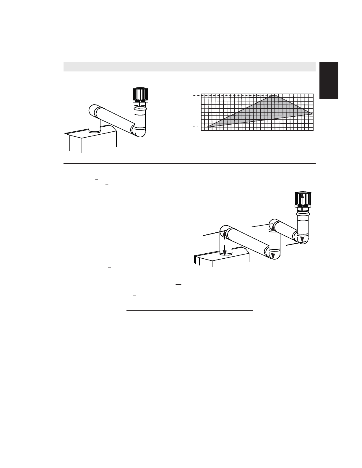
(HT) > (VT)
Simple venting configurations.
See graph to determine the required vertical rise VT for the
required horizontal run HT.
REQUIRED
VERTICAL
RISE IN FEET
(METERS) V
T
HORIZONTAL VENT RUN PLUS OFFSET IN FEET (METERS) H
T
For vent configurations requiring more than two 90° elbows the following formulas apply:
Formula 1: HT < 3V
T
Formula 2: HT + VT< 40 feet (12.2m)
Example:
V1= 2 FT (0.6m)
V2= 1 FT (0.3m)
V3= 1.5 FT (0.5m)
VT= V1+V2+V3= 2FT (0.6m) + 1FT (0.3m) + 1.5FT (0.5m) = 4.5FT (1.4m)
H1= 6 FT (1.8m)
H2= 2 FT (0.6m)
HR= H1+ H2= 6FT (1.8m) + 2FT (0.6m) = 8 FT (2.4m)
HO= .03 (four 90° elbows - 90°)
= .03 (360° - 90°) = 8.1 FT (2.5m)
HT= HR+ HO= 8FT (2.4m) + 8.1FT (2.5m) = 16.1FT (4.9m)
HT+ VT= 16.1FT (4.9m) + 4.5FT (1.4m) = 20.6 FT (6.3m)
Formula 1: HT < 3V
T
3VT= 3FT (0.9m) x 4.5FT (1.4m) = 13.5FT (4.1m)
16.1FT (4.9m) > 13.5FT (4.1m)
Since this formula is not met, this vent configuration is unacceptable.
Formula 2: HT + VT< 40 feet (12.2m)
20.6FT (6.3m) < 40 (12.2m)
Since only formula 2 is met, this vent configuration is unacceptable and a new appliance location or vent configuration will
need to be established to satisfy both formulas.
The shaded area within the lines represents acceptable
values for HTand V
T
0
5
(1.5)10(3.1)15(4.6)20(6.1)
10 (3.1)
20 (6.1)
3 (0.9)
25
(7.6)30(9.1)
19 (5.8)
90°
V
1
V
2
H
1
H
2
90°
90°
90°
V
3
18.1_2B
18
(5.5)
2 (0.6)
Page 16
16
W415-1276 / A / 05.09.14
EN
For optimum performance it is recommended that all horizontal runs have a minimum of 1/4" (6.4mm) rise
per foot (0.3m) using ß exible venting. For safe and proper operation of the appliance, follow the venting
instructions exactly.
For clearance to combustible materials from the vent pipe, see FRAMING section.
4.0 INSTALLATION
4.1 WALL AND CEILING PROTECTION
!
WARNING
ENSURE TO UNPACK ALL LOOSE MATERIALS FROM INSIDE THE FIREBOX PRIOR TO HOOKING UP
THE GAS AND ELECTRICAL SUPPLY.
IF YOUR APPLIANCE IS SUPPLIED WITH A REMOTE ENSURE THE REMOTE RECEIVER IS IN THE
“OFF” POSITION PRIOR TO HOOKING UP THE GAS AND ELECTRICAL SUPPLY TO THE APPLIANCE.
FOR SAFE AND PROPER OPERATION OF THE APPLIANCE, FOLLOW THE VENTING INSTRUCTIONS
EXACTLY.
ALL INNER EXHAUST AND OUTER INTAKE VENT PIPE JOINTS MAY BE SEALED USING EITHER RED
RTV HIGH TEMP SILICONE SEALANT W573-0002 (NOT SUPPLIED) OR BLACK HIGH TEMP MILL PAC
W573-0007 (NOT SUPPLIED) WITH THE EXCEPTION OF THE APPLIANCE EXHAUST FLUE COLLAR
WHICH MUST BE SEALED USING MILL PAC.
IF USING PIPE CLAMPS TO CONNECT VENT COMPONENTS, 3 SCREWS MUST ALSO BE USED TO
ENSURE THE CONNECTION CANNOT SLIP OFF.
DO NOT CLAMP THE FLEXIBLE VENT PIPE.
RISK OF FIRE, EXPLOSION OR ASPHYXIATION. IMPROPER SUPPORT OF THE ENTIRE VENTING
SYSTEM MAY ALLOW VENT TO SAG AND SEPARATE. USE VENT RUN SUPPORTS AND CONNECT
VENT SECTIONS PER INSTALLATION INSTRUCTIONS.
RISK OF FIRE, DO NOT ALLOW LOOSE MATERIALS OR INSULATION TO TOUCH THE VENT PIPE.
REMOVE INSULATION TO ALLOW FOR THE INSTALLATION OF THE ATTIC SHIELD AND TO
MAINTAIN CLEARANCES TO COMBUSTIBLES.
68.2B
!
WARNING
DO NOT FILL THE SPACE BETWEEN THE VENT PIPE AND ENCLOSURE WITH ANY TYPE OF
MATERIAL. DO NOT PACK INSULATION OR COMBUSTIBLES BETWEEN CEILING FIRESTOPS.
ALWAYS MAINTAIN SPECIFIED CLEARANCES AROUND VENTING AND FIRESTOP SYSTEMS.
INSTALL WALL SHIELDS AND FIRESTOPS AS SPECIFIED. FAILURE TO KEEP INSULATION OR
OTHER MATERIALS AWAY FROM VENT PIPE MAY CAUSE FIRE.
70.1
Page 17
17
W415-1276 / A / 05.09.14
EN
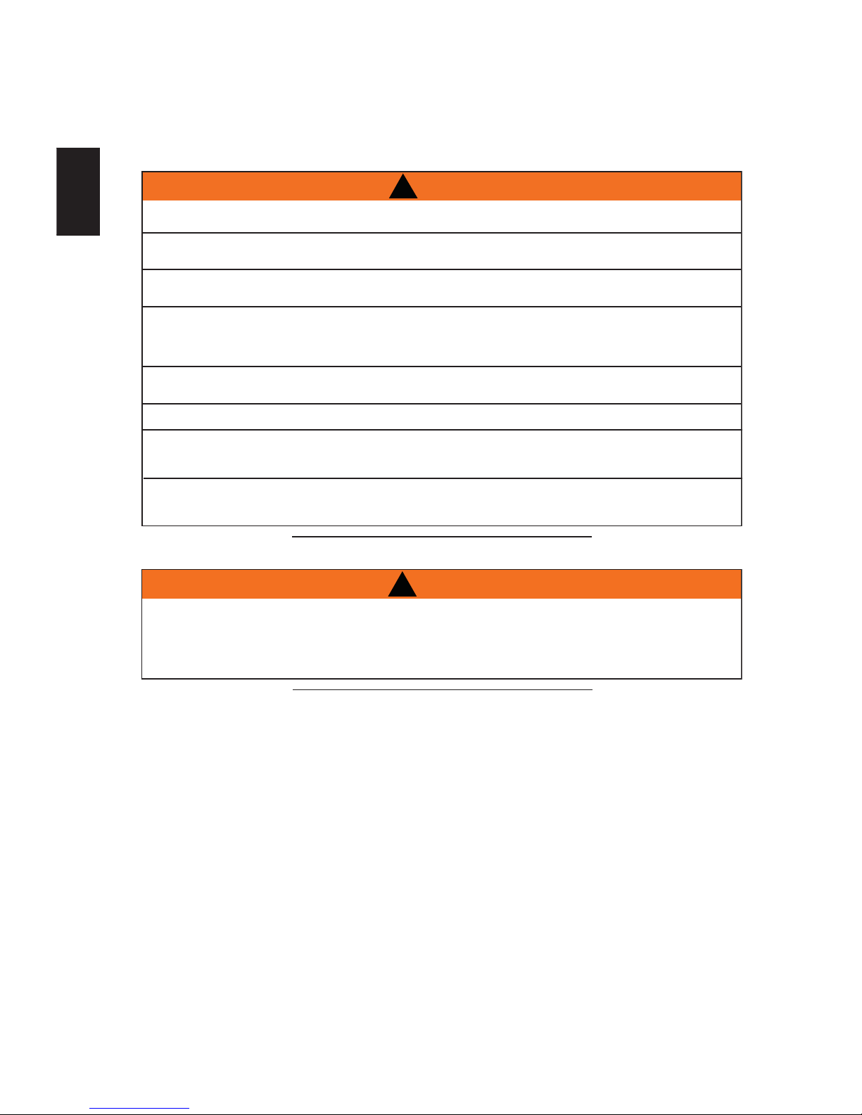
This application occurs when venting through a roof. Installation kits for
various roof pitches are available from your authorized dealer / distributor. See
accessories to order speciÞ c kits required.
A. Determine the air terminal location, cut and frame a square opening as
illustrated in the ceiling and the roof to provide the minimum 1 (25mm)
clearance between the vent pipe and any combustible material. Try to center
the vent pipe location midway between two joists to prevent having to cut
them. Use a plumb bob to line up the center of the openings. A vent pipe
shield will prevent any materials such as insulation, from Þ lling up the 1
(25mm) air space around the pipe. Nail headers between the joist for
extra support.
B. Apply a bead of caulking (not supplied) to the framework or to the Wolf
Steel vent pipe shield plate or equivalent (in the case of a Þ nished ceiling),
and secure over the opening in the ceiling. A Þ restop must be placed on the
bottom of each framed opening in a roof or ceiling that the venting system passes
through. Apply a bead of caulking all around and place a Þ restop spacer over
the vent shield to restrict cold air from being drawn into the room or around the
Þ replace. Ensure that both spacer and shield maintain the required clearance to
combustibles. Once the vent pipe is installed in its Þ nal position, apply sealant between the
pipe and the Þ restop assembly.
C. In the attic, slide the vent pipe collar down to cover up the open end of the shield and
tighten. This will prevent any materials, such as insulation, from Þ lling up the 1 (25mm) air
space around the pipe.
21.1
CAULKING
VENT PIPE
SHIELD
FIRESTOP
UNDERSIDE OF
JOIST
VENT
PIPE
COLLAR
VENT
PIPE
SHIELD
This application occurs when venting through an exterior wall.
Having determined the correct height for the air terminal
location, cut and frame a hole in the exterior wall as
illustrated to accommodate the Þ restop assembly.
Dry Þ t the Þ restop assembly before proceeding to
ensure the brackets on the rear surface Þ t to the
inside surface of the horizontal framing.
The length of the vent shield may be cut shorter for
combustible walls that are less than 8 1/2 (215.9mm)
thick but the vent shield must extend the full depth of
the combustible wall.
A. Apply a bead of caulking (not supplied) around the corner edge of
the inside surface of the Þ restop assembly, Þ t the Þ restop
assembly to the hole and secure using the 4 screws (supplied in your
manual baggie).
B. Once the vent pipe is installed in its Þ nal position, apply high temperature sealant W573-0007 (not
supplied) between the pipe and the Þ restop.
DETERMINE
THE
CORRECT
HEIGHT
CAULKING
FIRESTOP
SPACER
VENT
SHIELD
FINISHING
MATERIAL
20.7A
!
WARNING
THE FIRESTOP ASSEMBLY MUST BE INSTALLED WITH THE VENT SHIELD TO THE TOP.
TERMINALS MUST NOT BE RECESSED INTO A WALL OR SIDING MORE THAN THE DEPTH OF THE
RETURN FLANGE OF THE MOUNTING PLATE.
4.1.1 HORIZONTAL INSTALLATION
4.1.2 VERTICAL INSTALLATION
Page 18
18
W415-1276 / A / 05.09.14
EN
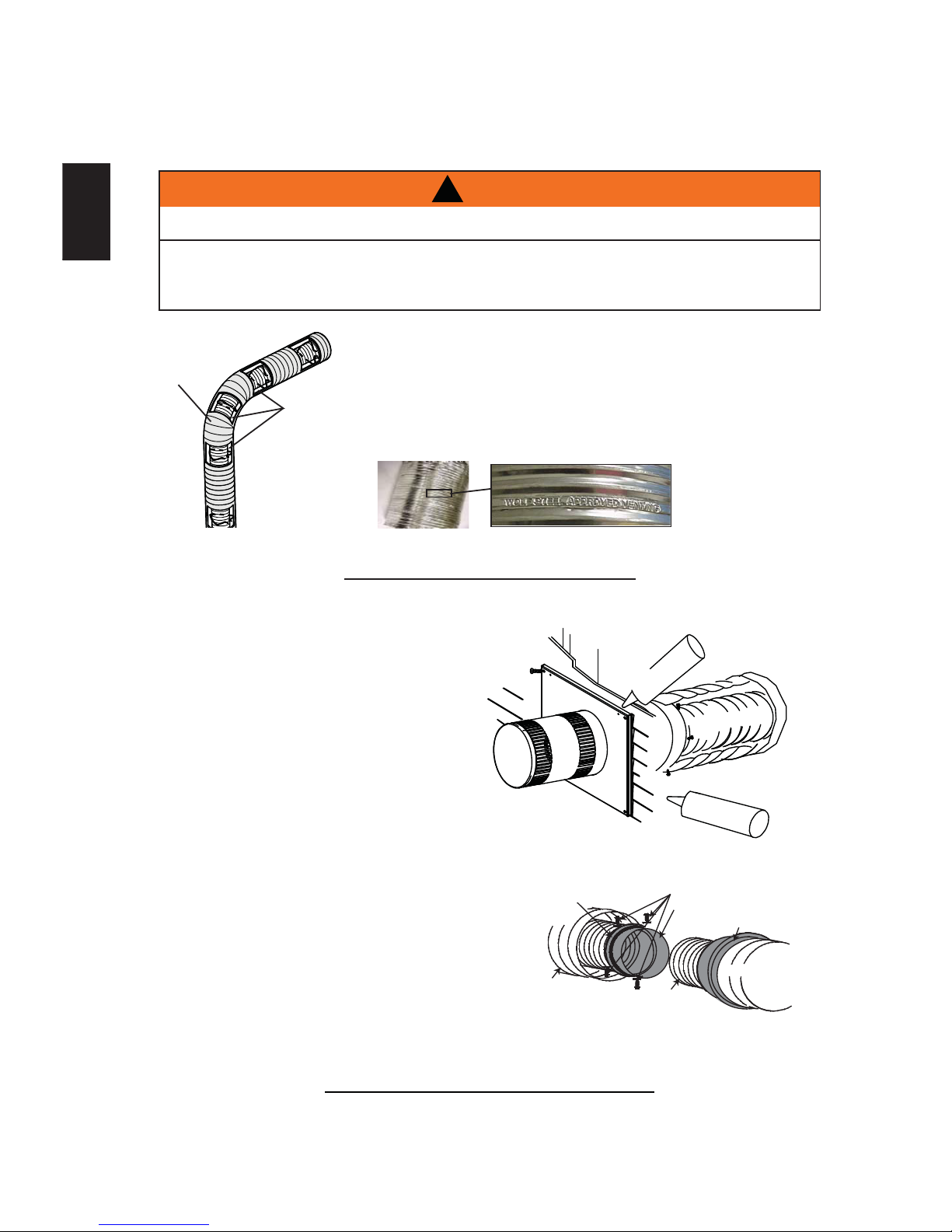
A. Stretch the inner ß ex pipe to the required
length needed for the Þ nished wall surface.
Apply a heavy bead of high temperature
sealant W573-0007 Mill Pac (not supplied) to
the inner sleeve of the air terminal. Slip the
vent pipe a minimum of 2 (50.8mm) over the
inner sleeve of the air terminal and secure
with 3 #8 screws.
B. Using the outer ß ex pipe, slide over the outer
combustion air sleeve of the air terminal
and secure with 3 #8 screws. Seal using
high temperature sealant W573-0002 (not
supplied).
C. Insert the vent pipes through the Þ restop
maintaining the required clearance to
combustibles. Holding the air terminal (lettering
in an upright, readable position), secure to the
exterior wall and make weather tight by sealing
with caulking (not supplied).
D. If more vent pipe needs to be used to
reach the Þ replace, couple them together
as illustrated. The vent system must be
supported approximately every 3 feet (0.9mm)
for both vertical and horizontal runs. Use
noncombustible strapping to maintain the
minimum 1 (25.4m m) clearance to combustibles.
The air terminal mounting plate may be recessed into the exterior wall or siding no greater than the depth
of its return ß ange.
23.3B
HI-TEMP
SEALANT
#8 X 1/2” SELF DRILLING
SCREWS & WASHERS
INNER COUPLER
OUTER COUPLER
OUTER
FLEX PIPE
INNER
FLEX PIPE
OUTER
FLEX PIPE
CAULKING
SCREWS
#10x2"
PIPE
OUTER FLEX
SEALANT
2" (50.8mm) OVERLAP
HI-TEMP
INNER FLEX
PIPE
4.2 USING FLEXIBLE VENT COMPONENTS
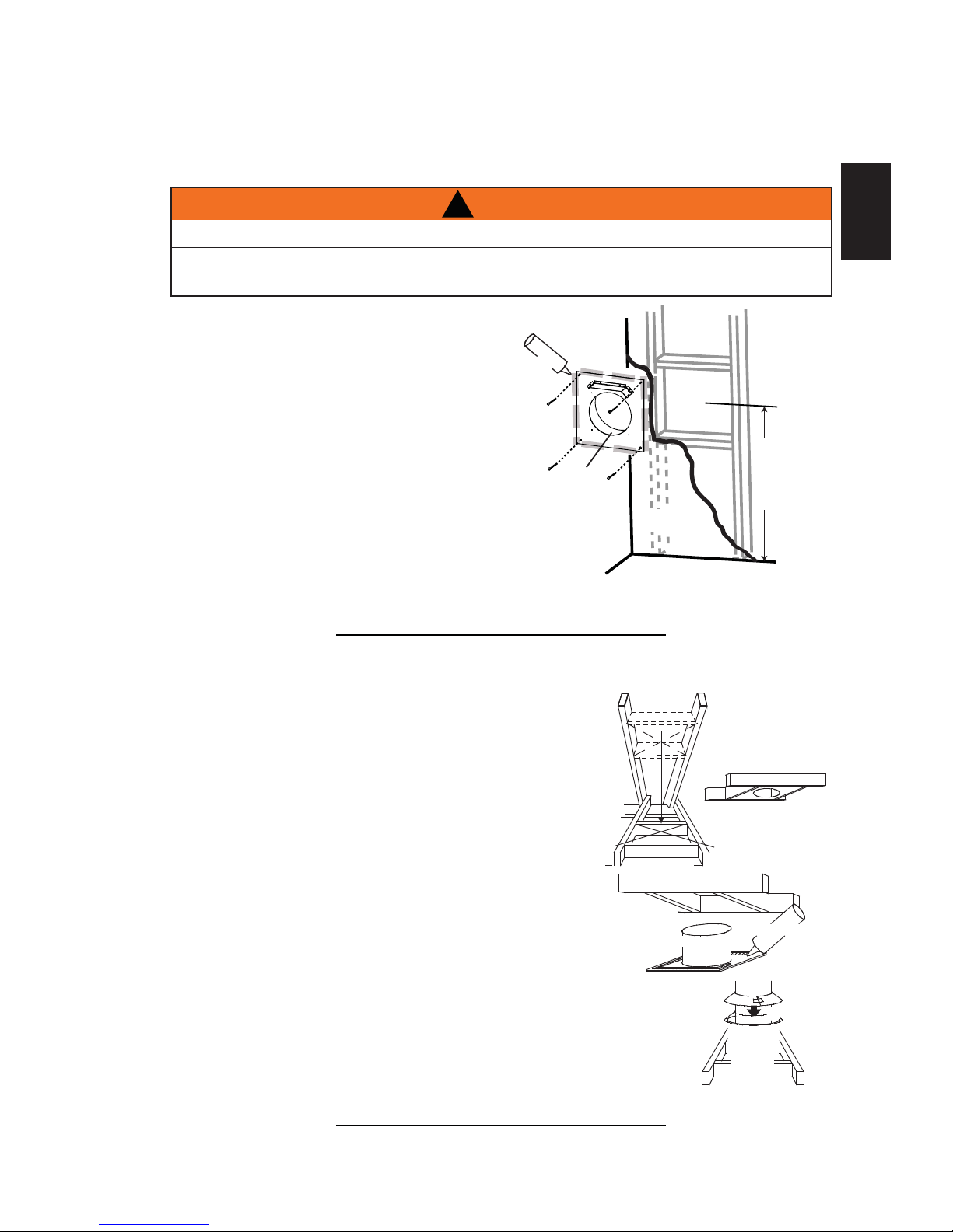
For safe and proper operation of the appliance, follow the venting
instructions exactly.
All inner ß ex pipe and outer ß ex pipe joints may be sealed using high
temperature sealant W573-0002 (not supplied) or the high temperature
sealant W573-0007 Mill Pac (not supplied). However, the high temperature
sealant W573-0007 Mill Pac (not supplied) must be used on the joint
connecting the inner ß ex pipe and the exhaust ß ue collar.
Use only approved ß exible vent pipe kits marked:
Wolf Steel Approved Venting as identiÞ ed
by the stamp only on the outer ß ex pipe.
22.1
ELBOW
SPACERS
DO NOT ALLOW THE INNER FLEX PIPE TO BUNCH UP ON HORIZONTAL OR VERTICAL RUNS AND ELBOWS.
KEEP IT PULLED TIGHT.
SPACERS ARE ATTACHED TO THE INNER FLEX PIPE AT PREDETERMINED INTERVALS TO MAINTAIN AN EVEN
AIR GAP TO THE OUTER FLEX PIPE. THIS GAP IS REQUIRED FOR SAFE OPERATION. A SPACER IS REQUIRED
AT THE START, MIDDLE AND END OF EACH ELBOW TO ENSURE THIS GAP IS MAINTAINED. THESE SPACERS
MUST NOT BE REMOVED.
!
WARNING
4.2.1 HORIZONTAL AIR TERMINAL INSTALLATION
Page 19

19
W415-1276 / A / 05.09.14
EN
A. Fasten the roof support to the roof using the screws provided. The
roof support is optional. In this case the venting is to be adequately
supported using either an alternate method suitable to the
authority having jurisdiction or the optional roof support.
B. Stretch the inner ß ex pipe to the required length. Slip the
inner ß ex pipe a minimum of 2 (51mm) over the inner pipe
of the air terminal connector and secure with 6 #8 screws.
Seal using a heavy bead of high temperature sealant
W573-0007 (not supplied).
C. Repeat using the outer ß ex pipe, using a heavy bead of
high temperature sealant W573-0002 (not supplied).
D. Thread the air terminal connector / vent pipe assembly down
through the roof. The air terminal must be positioned vertically
and plumb. Attach the air terminal connector to the roof support,
ensuring that the top of the air terminal is 16 (406mm) above the
highest point that it penetrates the roof.
E. Remove nails from the shingles, above and to the sides of the
air terminal connector. Place the ß ashing over the air terminal
connector leaving a min. 3/4 (19mm) of the air terminal connector
showing above the top of the ß ashing. Slide the ß ashing
underneath the sides and upper edge of the shingles. Ensure that
the air terminal connector is properly centred within the ß ashing,
giving a 3/4 (19mm) margin all around. Fasten to the roof.
Do not nail through the lower portion of the ß ashing. Make
weather-tight by sealing with caulking. Where possible, cover
the sides and top edges of the ß ashing with rooÞ ng material.
F. Aligning the seams of the terminal and air terminal connector,
place the terminal over the air terminal connector making
sure the vent pipe goes into the hole in the terminal. Secure
with the three screws provided.
G. Apply a heavy bead of weatherproof caulking 2 (51mm)
above the ß ashing. Install the storm collar around the air
terminal and slide down to the caulking. Tighten to ensure
that a weather-tight seal between the air terminal and the
collar is achieved.
H. If more vent pipe needs to be used to reach the Þ replace see HORIZONTAL AIR TERMINAL
INSTALLATION section.
24.2A
STORM COLLAR
FLASHING
CAULKING
WEATHER
SEALANT
2” (51mm)
AIR INLET
BASE
ROOF SUPPORT
INNER FLEX PIPE
INNER PIPE
HIGH
TEMPERATURE
SEALANT
AIR
TERMINAL
CONNECTOR
OUTER FLEX PIPE
MAINTAIN A MINIMUM 2” (51mm) SPACE BETWEEN THE AIR INLET BASE AND THE STORM COLLAR.
!
WARNING
4.2.2 VERTICAL AIR TERMINAL INSTALLATION
Page 20

20
W415-1276 / A / 05.09.14
EN
This appliance is also certiÞ ed to be installed as an OEM (Original Equipment Manufacturer) installation
in a manufactured home (U.S. only) or mobile home and must be installed in accordance with the
manufacturers instructions and the Manufactured Home Construction and Safety Standard, Title 24 CFR,
Part 3280, in the United States or the Mobile Home Standard, CAN/CSA Z240 MH Series, in Canada. This
appliance is only for use with the type(s) of gas indicated on the rating plate.
29.1A
This Mobile/Manufactured Home Listed appliance comes factory equipped with a means to secure the unit. Built
in appliances are equipped with 1/4 (6.4mm) diameter holes located in the front left and right corners of the
base. Use #10 hex head screws, inserted through the holes in the base to secure. For free standing products
contact your local authorized dealer / distributor for the appropriate securing kit. For mobile home installations, the
appliance must be fastened in place. It is recommended that the appliance be secured in all installations. Always
turn off the pilot and the fuel supply at the source, prior to moving the mobile home. After moving the mobile home
and prior to lighting the appliance, ensure that the logs are positioned correctly.
This appliance is certiÞ ed to be installed in an aftermarket permanently located, manufactured (mobile)
home, where not prohibited by local codes.
This appliance is only for use with the type of gas indicated on the rating plate. This appliance is not
convertible for use with other gases, unless a certiÞ ed kit is used.
A conversion kit is supplied with the mobile home appliance.
Conversion Kits
This appliance is Þ eld convertible between Natural Gas (NG) and Propane (LP).
To convert from one gas to another consult your Authorized dealer/distributor.
A. Install the inner ß ex pipe to the appliance. Secure with 3 screws
and ß at washers. Seal the joint and screw holes using the high
temperature sealant W573-0007 (not supplied).
B. Install the outer ß ex pipe to the appliance. Attach and seal the
joints using the high temperature sealant Mill-Pac.
28.1B
2” (50.8mm)
OVERLAP
HIGH TEMP
SEALANT
#8 X 1/2”
SELF
DRILLING
SCREWS
4.2.3 APPLIANCE VENT CONNECTION
4.3 MOBILE HOME INSTALLATION
Page 21

21
W415-1276 / A / 05.09.14
EN
4.4 GAS INSTALLATION
30.1
Installation and servicing to be done by a qualiÞ ed installer. Do not use open ß ame.
Move the appliance into position and secure.
If equipped with a ß ex connector the appliance is designed to accept a 1/2 (13mm) gas supply.
Without the connector it is designed to accept a 3/8 (9.5mm) gas supply. The appliance is equipped
with a manual shut off valve to turn off the gas supply to the appliance.
Connect the gas supply in accordance to local codes. In the absence of local codes, install to the
current CAN/CSA-B149.1 Installation Code in Canada or to the current National Fuel Gas Code, ANSI
Z223.1 / NFPA 54 in the United States.
When ß exing any gas line, support the gas valve so that the lines are not bent or kinked.
Check for gas leaks by brushing on a soap and water solution.
!
WARNING
RISK OF FIRE, EXPLOSION OR ASPHYXIATION. ENSURE THERE ARE NO IGNITION SOURCES SUCH AS
SPARKS OR OPEN FLAMES.
SUPPORT GAS CONTROL WHEN ATTACHING GAS SUPPLY PIPE TO PREVENT DAMAGING GAS LINE.
ALWAYS LIGHT THE PILOT WHETHER FOR THE FIRST TIME OR IF THE GAS SUPPLY HAS RUN OUT
WITH THE GLASS DOOR OPENED OR REMOVED. PURGING OF THE GAS SUPPLY LINE SHOULD BE
PERFORMED BY A QUALIFIED SERVICE TECHNICIAN. ASSURE THAT A CONTINUOUS GAS FLOW IS AT
THE BURNER BEFORE CLOSING THE DOOR. ENSURE ADEQUATE VENTILATION. FOR GAS AND
ELECTRICAL LOCATIONS, SEE “DIMENSION” SECTION.
ALL GAS CONNECTIONS MUST BE CONTAINED WITHIN THE APPLIANCE WHEN COMPLETE.
HIGH PRESSURE WILL DAMAGE VALVE. DISCONNECT GAS SUPPLY PIPING BEFORE TESTING GAS
LINE AT TEST PRESSURES ABOVE 1/2 PSIG.
VALVE SETTINGS HAVE BEEN FACTORY SET, DO NOT CHANGE.
NOTE: Connect the gas supply to the 1/2" shut off and ß ex connector (supplied). Ensure gas supply is
secured.
Page 22

22
W415-1276 / A / 05.09.14
EN
It is best to frame your appliance after it is positioned and the vent system is installed. Use the steel stud frame
provided.
5.0 FRAMING
!
WARNING
RISK OF FIRE!
IN ORDER TO AVOID THE POSSIBILITY OF EXPOSED INSULATION OR VAPOUR BARRIER COMING
IN CONTACT WITH THE APPLIANCE BODY, IT IS RECOMMENDED THAT THE WALLS OF THE
APPLIANCE ENCLOSURE BE “FINISHED” (IE: DRYWALL / SHEETROCK), AS YOU WOULD FINISH
ANY OTHER OUTSIDE WALL OF A HOME. THIS WILL ENSURE THAT CLEARANCE TO
COMBUSTIBLES IS MAINTAINED WITHIN THE CAVITY.
DO NOT NOTCH THE FRAMING AROUND THE APPLIANCE STAND-OFFS. FAILURE TO MAINTAIN
AIR SPACE CLEARANCE MAY CAUSE OVER HEATING AND FIRE. PREVENT CONTACT WITH
SAGGING OR LOOSE INSULATION OR FRAMING AND OTHER COMBUSTIBLE MATERIALS. BLOCK
OPENING INTO THE CHASE TO PREVENT ENTRY OF BLOWN-IN INSULATION. MAKE SURE
INSULATION AND OTHER MATERIALS ARE SECURED.
WHEN CONSTRUCTING THE ENCLOSURE ALLOW FOR FINISHING MATERIAL THICKNESS TO
MAINTAIN CLEARANCES. FRAMING OR FINISHING MATERIAL CLOSER THAN THE MINIMUMS
LISTED MUST BE CONSTRUCTED ENTIRELY OF NON-COMBUSTIBLE MATERIALS. MATERIALS
CONSISTING ENTIRELY OF STEEL, IRON, BRICK, TILE, CONCRETE, SLATE, GLASS OR PLASTERS,
OR ANY COMBINATION THEREOF ARE SUITABLE. MATERIALS THAT ARE REPORTED AS PASSING
ASTM E 136, STANDARD TEST METHOD FOR BEHAVIOUR OF MATERIALS IN A VERTICAL TUBE
FURNACE AT 1382° F (750°C) AND UL763 SHALL BE CONSIDERED NON-COMBUSTIBLE
MATERIALS.
MINIMUM CLEARANCE TO COMBUSTIBLES MUST BE MAINTAINED OR A SERIOUS FIRE HAZARD
COULD RESULT.
THE APPLIANCE REQUIRES A MINIMUM ENCLOSURE HEIGHT. MEASURE FROM THE APPLIANCE
BASE.
IF STEEL STUD FRAMING KITS WITH CEMENT BOARD ARE PROVIDED, OR SPECIFIED IN THE
INSTALLATION INSTRUCTIONS. THEY MUST BE INSTALLED.
FINISHING MUST BE DONE USING A NON-COMBUSTIBLE MATERIAL PLACED FLUSH WITH THE
FRONT FACE OF THE UNIT AND EXTENDING FROM THE TOP OF THE UNIT SUCH AS
CEMENT BOARD, CERAMIC TILE, MARBLE, ETC. DO NOT USE WOOD OR DRYWALL.
ANY FIRE RATED DRYWALL IS NOT ACCEPTABLE.
71.1B
Maintain these minimum clearances to combustibles from appliance and vent surfaces:
Appliance framing:
Use steel stud framing provided.
Non- Combustible Appliance Þ nishing:
Front - 6" (152mm) to sides of appliance opening
- 13" (330mm) above appliance opening
Combustible Appliance Þ nishing:
- 88" (2235mm) from bottom of appliance to enclosure top
- 5" (127mm) to top of vent pipe*
- 2" (51mm) to sides and bottom of vent pipe*
*HORIZONTAL VENT SECTIONS: A minimum clearance of 5" (127mm) to the top and 2" (51mm to the sides and
bottom of the vent pipe on all horizontal runs to combustibles is required. Horizontal vent sections within enclosures
require a minimum clearance of 11 1/2" (292mm) at the top of the vent pipe, see MINIMUM CLEARANCE TO
COMBUSTIBLE ENCLOSURES section. Use Þ restop spacer W010-3247 (supplied).
*VERTICAL VENT SECTIONS: A minimum of 1" (25mm) all around the vent pipe on all vertical runs to
combustibles is required except for clearances in appliance enclosures. Vertical vent sections within enclosures
require a minimum clearance of 2" (51mm) around the vent pipe. Use Þ restop spacer W500-0681 (not supplied).
Ceiling height
is minimum 24"
(610mm) from the
top of the appliance
opening.
Page 23

23
W415-1276 / A / 05.09.14
EN
* When constructing the enclosure allow for Þ nishing material thickness to maintain clearances.
IMPORTANT: Before Þ nishing in the appliance test the operation using the remote control, cycling it
through all of its different modes, see OPERATION section. Should trouble shooting be required,
access to the controls can be made through the pre-Þ nishing access panel.
88"
(2235mm)
MINIMUM
57 3/8"
(1457mm)
29 3/8"
(746mm)*
55 1/4"
(1403mm)
Page 24

24
W415-1276 / A / 05.09.14
EN
îç íñèþ
Åéìê³³Ã
лй нсию Епмлй³³Г
îç íñèþ
Åéìê³³Ã
лй нсию Епмлй³³Г
êþ
Åïëî³³Ã
лй нсию Епмлй³³Г
îþ
Åëï³³Ã
про псмю Еолзй³³Г
êç ïñèþ
Епйлл³³Г
Page 25

25
W415-1276 / A / 05.09.14
EN
!
WARNING
Joint Compound where required
Joint compounds such as Durabond 90 and tapes that are resilient to heat and cracking should be used when
taping and mudding seams.
Setting tiles and grouting
We recommend you use tiles with a dry butt joint to be installed using a two-part mortar with an acrylic latex
additive, such as Mapei Kerabond/Kerlastic, to allow for slight movement in the normal operation of the appliance.
If grout is used between the tiles, a polymer-based grout, such as Mapei Ultracolour plus, is recommended.
Primer/Paint
For a painted surface, use a 100% acrylic latex primer and Þ nish coat. Light coloured paints may discolour.
A NON-COMBUSTIBLE FINISHING MATERIAL BORDER, SUCH AS BRICK, MARBLE, GRANITE, ETC.
IS REQUIRED. FINISHING WITH JUST NON-COMBUSTIBLE BOARD TO THE SIDES AND TOP OF THE
APPLIANCE IS NOT ALLOWED.
THE SURFACE ABOVE THE APPLIANCE GETS VERY HOT. IF PROPER FINISHING MATERIALS ARE
NOT USED, CRACKING CAN OCCUR.
êþ
Åïëî³³Ã
NON-
COMBUSTBLE
BOARD
REQUIRED
With the frame assembly in place, use drywall screws to
install the non-combustible board sides (1) and center (2).
5.1 INSTALLING NON-COMBUSTIBLE BOARD
Page 26

26
W415-1276 / A / 05.09.14
EN
Depending on Þ nishing material, the frame assembly can be adjusted out from the unit by 1 3/4" (44mm), as
shown below:
1 3/4"
(44mm)
1 3/4"
(44mm)
NOTE: Framing dimensions will vary depending on Þ nishing material thickness.
Thick Finishing Material Thin Finishing Material
Page 27

27
W415-1276 / A / 05.09.14
EN
IMPORTANT: The HDX52 requires a minimum inside enclosure height of 88" (2235mm), measured from the
bottom of the appliance. For temperature requirements, this area must be left unobstructed. It is recommended
that the enclosure be ventilated at the top and bottom to circulate the air.
èèþ
îîíë³³ ö
УЧТЧУЛУ
ЫТЭФСНЛОЫ
ШЫЧЩШМ
ìï éñèþ
ïðêì³³
УЧТЧУЛУ
éï ïñîþ
ïèïê³³
УЧТЧУЛУ
ÐÔËÍ Î×ÍÛ ö
îþ
ëï³³
ëþ
ïîé³³
ïï ïñîþ
îçî³³
УЧТЧУЛУ цц
УЧТЧУЛУ
êþ
ïëî³³
ЭСУЮЛНМЧЮФЫ
УЯМЫОЧЯФ
МСР СЪ ЫТЭФСНЛОЫ
ЮОЧЭХ
НМЫЫФ НМЛЬ
ЪОЯУЧТЩ
ÌÑÐ ÑÚ
ЪЧОЫРФЯЭЫ
СРЫТЧТЩ
ð’ øð³³÷ ×Ú ÒÑÒó
ЭСУЮЛНМЧЮФЫ ЪЧТЧНШЧТЩ
ЧН ЛНЫЬ НЛЭШ ЯН ЮОЧЭХ
ЯТЬ НМСТЫ
ТСТуЭСУЮЛНМЧЮФЫ
УЯМЫОЧЯФ
NOTE: JOINT COMPOUNDS AND TAPES
THAT ARE RESILIENT TO HEAT AND
CRACKING SHOULD BE USED WHEN
TAPING AND MUDDING SEAMS.
SAFETY SCREEN
** Within the appliance enclosure a 11 1/2" (292mm) clearance between the top of the vent pipe and combustible material
is required. All other clearance, including where the vent exits the enclosure are subject to 2" (51mm) to the sides and
bottom and 5" (127mm) to the top for horizontal and 1" (25mm) for vertical.
!
WARNING
RISK OF FIRE!
THE FRONT OF THE APPLIANCE MUST BE FINISHED WITH ANY NON-COMBUSTIBLE MATERIALS
SUCH AS BRICK, MARBLE, GRANITE, ETC., PROVIDED THAT THESE MATERIALS DO NOT COVER
THE APPLIANCE OPENING.
THE STEEL STUD FRAMING KITS WITH CEMENT BOARD PROVIDED MUST BE INSTALLED.
5.2 MINIMUM CLEARANCE TO COMBUSTIBLE ENCLOSURES
Page 28

28
W415-1276 / A / 05.09.14
EN
* Within the appliance enclosure a 11 1/2" (292mm) clearance between the top of the vent pipe and
combustible materials is required. All other clearances within the enclosure, including where the vent pipe exits
the enclosure are subject to 2" (51mm) to the sides and bottom and 5" (127mm) to the top for horizontal and
1" (25mm) for vertical.
** See venting section.
IMPORTANT: THE FIRESTOP ASSEMBLY PROVIDED MUST BE USED WHEN THE VENT PIPES PASS
THROUGH ANY WALL OR ARE TERMINATED HORIZONTALLY.
éï ïñîþ
ïèïê³³
îþ
ëï³³
ìï éñèþ
ïðêì³³
ëë ïñìþ
ïìðí³³
èèþ
îîíë³³
îþ
ëï³³
ëþ
ïîé³³
ЪЧОЫНМСР
ЯННЫУЮФЗ
ïï ïñîþ
îçî³³
НМЫЫФ НМЛЬ
ЪОЯУЧТЩ
ТСТуЭСУЮЛНМЧЮФЫ
УЯМЫОЧЯФ
р’ ЧЪ ТСТуЭСУЮЛНМЧЮФЫ
ЪЧТЧНШЧТЩ УЯМЫОЧЯФ
ЧН ЛНЫЬ НЛЭШ ЯН
ЮОЧЭХ ЯТЬ НМСТЫт
êë éñèþ
ïêéí³³
ЫТЭФСНЛОЫ
ШЫЧЩШМ
Page 29

29
W415-1276 / A / 05.09.14
EN
Combustible mantel clearance can vary according to the mantel depth. Use the graph to help evaluate the
clearance needed.
0
3 4 7
14
16
1 2 5 6
12
MANTEL DEPTH
8
10
6
4
18
20
8 9
22
ø þ ÷
ø þ ÷
MANTEL DIMENSIONS
Ref Height Depth
A 42 (1067mm)
B 6 (152mm) 2 (51mm)
C 8 (203mm) 4 (102mm)
D 10 (254mm) 6 (152mm)
E 12 (305mm) 8 (203mm)
E
D
C
B
A
TOP OF
OPENING
5.3 MINIMUM COMBUSTIBLE MANTEL CLEARANCES
!
WARNING
RISK OF FIRE, MAINTAIN ALL SPECIFIED AIR SPACE CLEARANCES TO COMBUSTIBLES. FAILURE
TO COMPLY WITH THESE INSTRUCTIONS MAY CAUSE A FIRE OR CAUSE THE APPLIANCE TO
OVERHEAT. ENSURE ALL CLEARANCES (I.E. BACK, SIDE, TOP, VENT, MANTEL, FRONT, ETC.) ARE
CLEARLY MAINTAINED.
WHEN USING PAINT OR LACQUER TO FINISH THE MANTEL, THE PAINT OR LACQUER MUST BE
HEAT RESISTANT TO PREVENT DISCOLOURATION.
73.1
Page 30

30
W415-1276 / A / 05.09.14
EN
!
WARNING
RISK OF FIRE!
NEVER OBSTRUCT THE FRONT OPENING OF THE APPLIANCE.
THE FRONT OF THE APPLIANCE MUST BE FINISHED WITH ANY NON-COMBUSTIBLE MATERIALS
SUCH AS BRICK, MARBLE, GRANITE, ETC., PROVIDED THAT THESE MATERIALS DO NOT GO
BELOW THE SPECIFIED DIMENSION AS ILLUSTRATED.
DO NOT STRIKE, SLAM OR SCRATCH GLASS. DO NOT OPERATE APPLIANCE WITH GLASS
REMOVED, CRACKED, BROKEN OR SCRATCHED.
FACING AND/OR FINISHING MATERIAL MUST NEVER OVERHANG INTO THE APPLIANCE OPENING.
THE GLASS DOOR ASSEMBLY IS DESIGNED TO PIVOT FORWARD WHEN RELIEVING EXCESS
PRESSURE THAT MIGHT OCCUR. FINISHING OR OTHER MATERIALS MUST NOT BE LOCATED IN
THE OPENING SURROUNDING THE DOOR AS THIS WILL INTERFERE WITH THE DOORS ABILITY TO
RELIEVE THE PRESSURE.
72.6
6.0 FINISHING
!
WARNING
GLASS MAY BE HOT, DO NOT TOUCH GLASS UNTIL COOLED.
THE DOOR LATCHES ARE PART OF A SAFETY SYSTEM AND MUST BE PROPERLY ENGAGED. DO
NOT OPERATE THE APPLIANCE WITH LATCHES DISENGAGED.
FACING AND/OR FINISHING MATERIALS MUST NOT INTERFERE WITH AIR FLOW THROUGH AIR
OPENINGS, LOUVRES OPENINGS, OPERATION OF LOUVRES OR DOORS OR ACCESS FOR
SERVICE. OBSERVE ALL CLEARANCES WHEN APPLYING COMBUSTIBLE MATERIALS.
BEFORE DOOR IS REMOVED TURN THE APPLIANCE OFF AND WAIT UNTIL APPLIANCE IS COOL TO
THE TOUCH. DOORS ARE HEAVY AND FRAGILE SO HANDLE WITH CARE.
75.1
6.1 SCREEN DOOR REMOVAL / INSTALLATION
A. There are 4 hanging tabs
securing the screen onto the
door. The tabs are on the right
and left sides of the door.
B. Lift up and pull the screen away
from the unit to remove it from
the slots in the main door, refer
to Figure 1.
C. Reverse this process to install
the screen back onto the unit.
FIG. 1
SCREEN
GLASS DOOR
Page 31

31
W415-1276 / A / 05.09.14
EN
A. There are 4 spring latches securing the main
glass door, 2 of those latches are across the
top and 2 along the bottom. To access these
latches ensure the screen is removed.
B. Using the tool provided, pull the latch forward
and upwards / downwards, out of the slot in the
door, as shown. Repeat 3 times.
C. When all 4 latches have been released slide
the door forward and lift off of the 2 door slides.
D. Reverse this process to install the door.
IMPORTANT: Once latches are engaged,
test that the door is secure and will not
fall forward before letting go.
6.2 LATCH DOOR REMOVAL / INSTALLATION
LATCHES
THE 4 LATCHES ARE SHOWN IN THE ILLUSTRATION BELOW.
Page 32

32
W415-1276 / A / 05.09.14
EN
FIG. 1
A. Release the 4 door latches from the top and bottom of the door. Refer to LATCH DOOR REMOVAL /
INSTALLATION section.
B. Slide the glass door forward from the unit. It will sit on the door slides attached to the unit, refer to
Figure 1.
C. Lift the glass door off the door slides and away from the unit.
D. Reverse this process to install the screen back onto the unit.
6.3 GLASS DOOR REMOVAL / INSTALLATION
Page 33

33
W415-1276 / A / 05.09.14
EN
FRONT OF
APPLIANCE
WARNING: Non-combustible facing material must not protrude more than 3/4” (19mm) from the top,
and/or sides of the appliance. If it does, it is considered a non-combustible mantel and must meet the
non-combustible mantel clearance requirements.
71.3A
3/4” (19mm)
FRONT OF
APPLIANCE
TOP VIEWSIDE VIEW
NON-COMBUSTIBLE
FACING MATERIAL
NON-COMBUSTIBLE
FACING MATERIAL
FINISH
MATERIAL
FINISH
MATERIAL
3/4” (19mm)
See instructions accompanying burner assembly (sold separately).
6.4 BURNER INSTALLATION
6.5 NON-COMBUSTIBLE FACING MATERIAL
LOGO
6.6 LOGO PLACEMENT
NON-COMBUSTIBLE
BOARD
Non-combustible facing material must not protrude from the top and/or sides of the
appliance. If it does, it is considered a non-combustible mantel and must meet the noncombustible mantel clearance requirements.
Page 34

34
W415-1276 / A / 05.09.14
EN
7.0 ELECTRICAL INFORMATION
!
WARNING
DO NOT USE THIS APPLIANCE IF ANY PART HAS BEEN UNDER WATER. CALL A QUALIFIED
SERVICE TECHNICIAN IMMEDIATELY TO HAVE THE APPLIANCE INSPECTED FOR DAMAGE TO THE
ELECTRICAL CIRCUIT.
RISK OF ELECTRICAL SHOCK OR EXPLOSION. DO NOT WIRE 110V TO THE VALVE OR TO THE
APPLIANCE WALL SWITCH. INCORRECT WIRING WILL DAMAGE CONTROLS.
ALL WIRING SHOULD BE DONE BY A QUALIFIED ELECTRICIAN AND SHALL BE IN COMPLIANCE
WITH LOCAL CODES. IN THE ABSENCE OF LOCAL CODES, USE THE CURRENT CSA22.1 CANADIAN
ELECTRIC CODE IN CANADA OR THE CURRENT NATIONAL ELECTRIC CODE ANSI/NFPA NO. 70 IN
THE UNITED STATES.
ALWAYS LIGHT THE PILOT WHETHER FOR THE FIRST TIME OR IF THE GAS SUPPLY HAS RAN OUT,
WITH THE GLASS DOOR OPENED OR REMOVED.
69.2
It is necessary to hard wire this appliance.
Permanently framing the appliance with an enclosure, requires the appliance junction box to be hard wired.
This appliance must be electrically connected and grounded in accordance with local codes. In the absence
of local codes, use the current CSA C22.1 Canadian electrical code in Canada or the ANSI/NFPA 70-1996
national electrical code in the United States.
7.1 HARD WIRING CONNECTION
L1
CABLE CONNECTOR
L2
ELECTRICAL COVER
7.2 RECEPTACLE WIRING DIAGRAM
Page 35

35
W415-1276 / A / 05.09.14
EN
7.3 BATTERY HOLDER INSTALLATION
NOTE: Screen must be removed to access the battery holder.
A. The battery holder must be
located within 8 feet of this side
of the appliance and must be
accessible for programming the
remote.
B. Install 4 AA batteries, ensure
that the positive and negative
ends correspond with those
identiÞ ed in the battery holder.
C. Install the battery holder into
a standard electrical switch
box. Determine an appropriate
location and install the electrical
box.
NOTE: Ensure the 3 position slider
switch is in the REMOTE position
(middle).
(4
)
A
A
B
a
tt
e
ri
e
s
RESET/PROGRAM BUTTON (PRG)
Page 36

36
W415-1276 / A / 05.09.14
EN
7.4 WIRING DIAGRAM
!
WARNING
DO NOT WIRE 110 VOLTS TO THE VALVE OR WALL SWITCH.
RESET
BUTTON
BATTERY HOLDER COMPLETE
NIGHT
LIGHT
BLOWER
WITH RESET BUTTON
W190-0048 (RECEIVER)
Page 37

37
W415-1276 / A / 05.09.14
EN
(
4
)
A
A
B
a
t
t
e
r
i
e
s
8.0 OPERATION
Low battery alarm
Key Lock
Room
Temperature
Night Light
Flame ON
Blower
Transmission
CPI mode
8.1 GENERAL TRANSMITTER LAYOUT
8.2 INITIALIZING THE TRANSMITTER/BATTERY HOLDER FOR THE FIRST TIME
A. Install the 4 AA batteries into the Proß ame 2 battery holder, note the polarity of the batteries and insert
as indicated on the cover (+/-).
B. Ensure the 3 position slider switch is switched to the REMOTE position (middle position).
C. Press the reset/programming button, use a small object such as a paper clip in order to reach the
button marked PRG, as shown in the illustration below.
D. The battery holder will beep 3 times to indicate that its ready to synchronize with the transmitter.
E. Install the 3 AAA batteries into the transmitter, as shown in the photograph below, then press the ON
button, The battery holder will beep 4 times to indicate that the transmitters command is accepted.
NOTE: THE INITIALIZING PROCESS MUST BE COMPLETED WITHIN 10 SECONDS OF PRESSING THE
RESET/PROGRAM BUTTON (PRG).
Low Battery Alarm
TRANSMITTER
RESET/PROGRAM
BUTTON (PRG)
BATTERY HOLDER
SLIDER SWITCH
(NOT AVAILABLE WITH THIS MODEL)
Page 38

38
W415-1276 / A / 05.09.14
EN
8.3 TEMPERATURE DISPLAY
A
. With the system in the
O
FF position, press the
Temperature Key and the Mode Key at the same
time to change from degrees F to C.
B. Look at the LCD screen on the Transmitter to
verify that a C or F is visible to the right of the
Room Temperature display.
35.5A
éí
pÚ
îí
pÝ
The remote control has six (6) ß ame levels. With the
system on and the ß ame level at the maximum, press
the Down Arrow Key once and it will reduce the ß ame
height by one step until the ß ame is turned off.
The Up Arrow Key will increase the ß ame height each
time it is pressed. If the Up Arrow Key is pressed while
the system is on but the ß ame is off, the ß ame will
come on the high position. A single beep will conÞ rm
reception of the command.
35.8A
éê
pÚ
ÑÚÚ
éê
pÚ
éê
pÚ
éê
pÚ
Ø·
FLAME OFF
FLAME AT LEVEL 1
FLAME AT LEVEL 5 FLAME AT “HI” LEVEL 6
8.4 FLAME HEIGHT
8.5 NIGHT LIGHT DIMMER CONTROL
The auxiliary function controls the Night Light
TM
with
dimmable control.
A. Use the Mode Key to guide you to the Night
Light icon.
B. The intensity of the output can be adjusted
through 6 levels. Use the UP/DOWN arrow
keys to adjust the output level. A single beep will
conÞ rm reception of the command.
35.21
éê
pÚ pÚ
ÑÚÚ
Page 39

39
W415-1276 / A / 05.09.14
EN
8.6 CONTINUOUS PILOT / INTERMITTENT PILOT (CPI / IPI) SELECTION
A. Use the Mode Key to guide you to the CPI mode
icon. Transmitter in the OFF position.
B. Press the UP/DOWN to switch between IPI and
CPI modes. A single BEEP will conÞ rm reception
of the command.
Note: If the system is equipped with a CPI/IPI
toggle switch, set the CPI/IPI to CPI position to
enable remote CPI operation. If the switch is set
to IPI then it will only work in IPI regardless of
what is set on the remote control handset.
35.22
éê éê
pÚ pÚ
×Ð×
ÝÐ×
8.7 KEY LOCK
This function will lock the keys to avoid unsupervised operation.
A. Press the MODE and UP keys at the same time.
B. To de-activate this function, press the MODE and UP keys at the same time.
35.10A
éê
pÚ
8.8 LOW BATTERY / MANUAL BYPASS
The life span of the remote batteries depends on various factors: quality of the
batteries, the number of ignitions, the number of changes to the room thermostat set
point, etc.
When the transmitter batteries are low, a Battery Icon will appear on the LCD
display before all battery power is lost. When the batteries are replaced this icon will
disappear.
Not applicable when plugged into 110V.
When the batteries are low, no beep will be emitted from the receiver when it
receives an ON/OFF command. This in an alert for the receiver that theres low battery. When the batteries ar
e
replaced the beep will be emitted from the receiver when the ON/OFF key is pressed.
If the batteries in the battery holder or transmitter are low, the appliance can be turned on manually by sliding
the three position slider switch on the battery holder to the ON position. This will bypass the remote control
feature and the appliance main burner will come on. Likewise, if you want to manually turn the appliance off,
slide the switch to the OFF position.
35.23
éê
pÚ
Page 40

40
W415-1276 / A / 05.09.14
EN
9.0 OPERATING INSTRUCTIONS
IF YOU DO NOT FOLLOW THESE INSTRUCTIONS EXACTLY, A FIRE OR EXPLOSION MAY RESULT
CAUSING PROPERTY DAMAGE, PERSONAL INJURY OR LOSS OF LIFE.
NEVER LEAVE CHILDREN OR OTHER AT RISK INDIVIDUALS ALONE WITH THE APPLIANCE.
ALWAYS LIGHT THE PILOT WHETHER FOR THE FIRST TIME OR IF THE GAS SUPPLY HAS RUN OUT WITH
THE GLASS DOOR OPENED OR REMOVED.
!
WARNING
FOR YOUR SAFETY READ BEFORE LIGHTING:
A.
This appliance is equipped with an ignition device which automatically lights the pilot. Do not try to light by hand.
B.
Before operating smell all around the appliance area for gas and next to the floor because some gas is heavier than
air and will settle on the floor.
C.
Do not use this appliance if any part has been under water. Immediately call a qualified service technician to inspect
the appliance and replace any part of the control system and any gas control which has been under water.
WHAT TO DO IF YOU SMELL GAS:
Turn off all gas to the appliance.
Open windows.
Do not try to light any appliance.
Do not touch any electric switch; do not use any phone
in your building.
LIGHTING INSTRUCTIONS
A.
Stop! Read the above safety information on this label.
B.
Remove batteries from transmitter.
C.
Turn off all electric power to the appliance.
D.
This appliance is equipped with an ignition device which automatically lights the pilot. Do not try to light the pilot by
hand.
E.
Open the glass door.
F.
Turn manual shutoff valve clockwise to off. Located behind the access panel.
G.
Wait five (5) minutes to clear out any gas. If you smell gas including near the floor,
STOP!
Follow “B” in the above
safety information on this label. If you don’t smell gas go to the next step.
H.
Turn manual shutoff valve counter-clockwise to on.
I.
Close the glass door.
J.
Turn on all electric power to the appliance and re-install batteries into the transmitter.
K.
Push the “ON” button on the transmitter. You should here an audible beep from the receiver
which indicates communication. (Refer to Appliance Operations for remote activation).
TO TURN OFF GAS
A. Turn off all electric power to the appliance if service is to be performed.
B. Access door inside the firebox must be removed to access the manual shutoff valve.
C. If alternate shut-off valve was installed it can be shutoff instead of going through the appliance to access
the appliance shut off valve.
Immediately call your gas supplier from a neighbor's
phone. Follow the gas supplier's instructions.
If you cannot reach your gas supplier, call the fire
department.
47.4
Ensure that a continuous gas flow is at the burner before installing the door. When lit for the first time, the
appliance will emit an odor for a few hours. This is a normal temporary condition caused by the “burn-in” of
paints and lubricants used in the manufacturing process and will not occur again. After extended periods of
non-operation such as following a vacation or a warm weather season, the appliance may emit a slight odor
for a few hours. This is caused by dust particles in the heat exchanger burning off. In both cases, open a
window to sufficiently ventilate the room.
Page 41

41
W415-1276 / A / 05.09.14
EN
9.1 RESTRICTING VERTICAL VENTS
Adjust the pilot screw to provide properly sized ß ame. Turn in a
clockwise direction to reduce the gas ß ow.
Check Pressure Readings:
Inlet pressure can be checked by turning screw (A) counter-
clockwise 2 or 3 turns and then placing pressure gauge tubing
over the test point. Gauge should read as described on the chart
below. Check that main burner is operating on HI.
Outlet pressure can be checked the same as above using
screw (B). Gauge should read as described on the chart
below. Check that main burner is operating on HI.
AFTER TAKING PRESSURE READINGS, BE SURE TO
TURN SCREWS CLOCKWISE FIRMLY TO RESEAL. DO
NOT OVERTORQUE.
Leak test with a soap and water solution.
Prior to pilot adjustment, ensure that the pilot assembly
has not been painted. If overspray or painting of the pilot
assembly has occurred remove the paint from the pilot
assembly, or replace. Fine emery
cloth or sandpaper can be used to
remove the paint from the pilot hood,
electrode and ß ame sensor.
39.1C
A
B
PILOT SCREW
FLAME MUST ENVELOP
UPPER 3/8” (9.5mm) TO 1/2”
(12.7mm) OF FLAME SENSOR
PILOT
BURNER
ELECTRODE
FLAME
SENSOR
3/8” - 1/2”
(9.5mm - 12.7mm)
Pressure
Inlet
Outlet
Natural Gas
(inches)
Natural Gas
(millibars)
Propane
(inches)
Propane
(millibars)
7"
(MIN. 4.5")
3.5"
13"
(MIN. 11")
10"
17.4mb
(MIN. 11.2mb)
8.7mb
32.4mb
(MIN. 27.4mb)
24.9mb
9.2 PILOT BURNER ADJUSTMENT
77.3
Vertical installations may display a very active ß ame. If this appearance is not desirable, the vent exit must
be restricted using a restrictor vent kit. Refer to ACCESORIES in the REPLACEMENTS section for the
appropriate kit. This will reduce the velocity of the exhaust gases, slowing down the ß ame pattern and creating
a more traditional gentle ß ame appearance. SpeciÞ c instructions are included with the kit.
Page 42

42
W415-1276 / A / 05.09.14
EN
HDX52
NG 3/8 (9.5mm)
LP 7/16" (11mm)
This appliance has an air shutter that has been factory set open according
to the chart below:
Regardless of venturi orientation, closing the air shutter will cause a more
yellow flame, but can lead to carboning. Opening the air shutter will cause a
more blue flame, but can cause flame lifting from the burner ports. The
flame may not appear yellow immediately; allow 15 to 30 minutes for the
final flame colour to be established.
AIR SHUTTER ADJUSTMENT MUST ONLY BE DONE BY A QUALIFIED
INSTALLER!
AIR
SHUTTER
OPENING
VENTURI
BURNER
ORIFICE
49.1
9.3 VENTURI ADJUSTMENT
Its important to periodically perform a visual check of the pilot and burner ß ames. Compare them to the
illustration provided. If any ß ames appear abnormal call a service person.
FLAME MUST ENVELOP
UPPER 3/8” (9.5mm) TO 1/2”
(12.7mm) OF FLAME SENSO
R
PILOT
BURNER
ELECTRODE
FLAME
SENSOR
3/8” - 1/2”
(9.5mm - 12.7mm)
54.1B
9.4 FLAME CHARACTERISTICS
MAXIMUM INPUT RATE
NG 55,000 BTU/HR
LP 55,000 BTU/HR
Page 43

43
W415-1276 / A / 05.09.14
EN
10.0 MAINTENANCE
CAUTION: Label all wires prior to disconnection when servicing controls. Wiring errors can cause improper
and dangerous operation. Verify proper operation after servicing. This appliance and its venting system
should be inspected before use and at least annually by a qualiÞ ed service person. The appliance area must
be kept clear and free of combustible materials, gasoline or other ß ammable vapors and liquids. The ß ow of
combustion and ventilation air must not be obstructed.
A. In order to properly clean the burner and pilot assembly, remove the logs, rocks and/or glass to
expose both assemblies.
B. Keep the control compartment, media, burner, air shutter opening and the area surrounding the logs
clean by vacuuming or brushing, at least once a year.
C. Check to see that all burner ports are burning. Clean out any of the ports which may not be burning or
are not burning properly.
D. Check to see that the pilot ß ame is large enough to engulf the ß ame sensor and/or thermocouple /
thermopile as well as reaches the burner.
E. Replace the cleaned logs, rocks or glass. Failure to properly position the media may cause carboning
which can be distributed in the surrounding living area.
F. Check to see that the main burner ignites completely on all openings when turned on. A 5 to 10
second total light-up period is satisfactory. If ignition takes longer, consult your local authorized dealer /
distributor.
G. Check that the gasketing on the sides, top and bottom of the door is not broken or missing. Replace if
necessary.
H. If for any reason the vent air intake system is disassembled, re-install and re-seal per the instructions
provided for the initial installation.
40.1B
MAINTENANCE
MAINTENANCE
MAINTENANCE
TURN OFF THE GAS AND ELECTRICAL POWER BEFORE SERVICING THE APPLIANCE.
APPLIANCE MAY BE HOT, DO NOT SERVICE UNTIL APPLIANCE HAS COOLED.
DO NOT USE ABRASIVE CLEANERS.
DO NOT PAINT THE PILOT ASSEMBLY.
!
WARNING
37.1B
!
WARNING
THE FIREBOX BECOMES VERY HOT DURING OPERATION. LET THE APPLIANCE COOL
COMPLETELY OR WEAR HEAT RESISTANT GLOVES BEFORE CONDUCTING SERVICE.
NEVER VACUUM HOT EMBERS.
DO NOT PAINT THE PILOT ASSEMBLY.
This appliance will require maintenance which should be planned on an annual basis.
Service should include cleaning, battery replacement, venting inspection and inspection of the burner,
media and Þ rebox. Refer to the door removal section and remove the door as instructed.
Carefully remove media if necessary (logs, glass, brick panels etc).
Using a vacuum with a soft brush attachment, gently remove any dirt, debris or carbon build up from the
logs, Þ rebox and burner. For glass media, follow the installation instructions for pre-cleaning.
Also gently remove any build-up on the pilot assembly including, if equipped; thermopile, thermocouple,
ß ame sensor and igniter.
NOTE: The ß ame sensor may require to be cleaned using a Þ ne steel wool or
Scotch- Brite scrubbing pad to remov e any oxides.
Clean the pilot assembly using a vacuum with a
soft brush attachment.
It is important that the pilot assembly is not painted.
Inspect all accessible gaskets and replace as required.
Access the blower, if equipped and clean using a soft brush and vacuum.
Re-assemble the various components in reverse order.
Inspect the relief system. The appliance relieves through the main glass door or through the ß aps on the
Þ rebox top. Ensure they open freely, and close sealed.
10.1 ANNUAL MAINTENANCE
Page 44

44
W415-1276 / A / 05.09.14
EN
Once the appliance has been framed and Þ nished, control access can only be achieved by removing the
access panel from the inside right side of the Þ rebox. The following sub sections take you through the steps
of accessing the control as if the appliance is installed.
*Prior to removing the control panel follow the DOOR REMOVAL process and then follow the media
removal instructions located under the MAINTENANCE section.
NOTE: IT WILL BE NECESSARY TO REPLACE THE GASKET (W290-0238) FOR THE ACCESS PLATE
IF THE UNIT HAS BEEN PREVIOUSLY OPERATED BEFORE REMOVING THE PLATE (W290-0238).
A. Remove the media from the appliance, follow removal instructions under the MEDIA REMOVAL
section.
B. Remove the right side brick / porcelain panel, follow removal instructions under the BRICK /
PORCELAIN PANEL REMOVAL section.
C. To remove the glass media trays to remove the glass burner, follow removal instructions under the
MEDIA TRAY section (glass burner only).
D. Remove the grate before removing the brick / porcelain panels, follow removal instructions under the
GRATE REMOVAL section (log burner only).
E. To access the controls remove the 8 screws securing the access plate from inside the Þ rebox.
F. Care should be taken to ensure avoiding damage to the gasket.
G. Reverse this process to install the control access. Ensure the access plate is well sealed to the
Þ replace.
RIGHT
SIDE
P
O
S
T
I
N
S
T
A
L
L
A
T
I
O
N
A
C
C
E
S
S
PRE INSTALLATION
ACCESS
10.2 CONTROL ACCESS
Page 45

45
W415-1276 / A / 05.09.14
EN
Refer to your burner manual which was shipped separate from the appliance.
A. Remove the 2 screws securing the brick panel brackets from the top left of the appliance.
B. Remove the left panel. NOTE: Care must be taken with the rear bafß e as it rests on the left and
right panels.
C. Remove the rear bafß e.
D. Repeat step (A) for the right side.
E. Remove the rear panel by lifting it up and out of the rear panel support.
A. Remove the 4 securing screws from the top / bottom left of the panel inside the Þ rebox, remove the
panel.
B. Repeat on the right side.
C. Remove the 4 securing screws from the top and bottom of the rear panel and remove.
A. Vacuum the media from the appliance.
B. Remove the 4 securing screws from the burner media tray and lift up and out, refer to Figure 1.
C. Carefully lift the bottom media tray from the appliance, refer to Figure 2.
Fig. 2
Fig. 1
10.3 BURNER REMOVAL
10.4 BRICK PANEL REMOVAL
10.5 PORCELAIN PANEL REMOVAL
10.6 MEDIA TRAY REMOVAL (GLASS ONLY)
Page 46

46
W415-1276 / A / 05.09.14
EN
Your appliance came equipped with our NIGHT LIGHT. The light has been
pre-wired and can be controlled by remote control.
It is recommended that the NIGHT LIGHT be in the off position when the
appliance is on.
If in the event the lamp or lens needs to be replaced, follow the
instructions below.
A. Shut off the electrical supply to the Þ replace.
B. Remove the 2 screws securing the relief door supports.
C. Carefully remove the relief door gasket.
NOTE: A new gasket may be required if damaged
(W290-0239).
D. Remove the 4 screws that secure the lens frame.
This frame retains the glass lens. The lamp can
now be accessed.NOTE: Do not handle the
lamp (bulb) with bare Þ ngers, protect with a
clean dry cloth.
E. The lamp will pull straight out of the socket.
Replace with Wolf Steel parts only, as lamp and
lens are special high temperature products.
F. When re-installing, ensure integrity of gasket seal.
THE FIREBOX MUST BE SEALED.
NOTE: Over tightening the screws could break the
lens.
SCREWS
FIREBOX
GASKET
LENS
FRAME
RELIEF DOOR
RELIEF DOOR
GASKET
RELIEF DOOR
SUPPORT
10.7 NIGHT LIGHT REPLACEMENT
Page 47

47
W415-1276 / A / 05.09.14
EN
5.1
DO NOT CLEAN GLASS WHEN HOT! DO NOT USE
ABRASIVE CLEANERS TO CLEAN GLASS.
Buff lightly with a clean dry soft cloth. Clean both sides
of the glass after the Þ rst 10 hours of operation with a
recommended Þ replace glass cleaner. Thereafter clean
as required. If the glass is not kept clean permanent
discoloration and / or blemishes may result.
HOT GLASS WILL
CAUSE BURNS.
DO NOT TOUCH GLASS
UNTIL COOLED.
NEVER ALLOW CHILDREN
TO TOUCH GLASS.
!
WARNING
6.1
If the appliance is equipped with plated parts, you must clean Þ ngerprints or other marks from the plated
surfaces before operating the appliance for the Þ rst time. Use a glass cleaner or vinegar and towel to clean.
If not cleaned properly before operating for the Þ rst time, the marks can cause permanent blemishes on
the plating. After the plating is cured, the Þ ngerprints and oils will not affect the Þ nish and little maintenance
is required, just wipe clean as needed. Prolonged high temperature burning with the door ajar may cause
discolouration on plated parts.
NOTE: The protective wrap on plated parts is best removed when the assembly is at room
temperature but this can be improved if the assembly is warmed, using a hair dryer or similar heat
source.
A. Place the door frame face down careful not to
scratch the paint.
B. Ensure the glass retainers are bent up prior to
replacing the glass and gasket.
C. Center the gasketed glass inside the door
frame with the thick side of the gasket
facing up.
D. Bend the glass retainers located along the edge
of the door frame over the gasket holding the
glass in place. Be careful not to break the glass.
!
WARNING
DO NOT USE SUBSTITUTE MATERIALS.
GLASS MAY BE HOT, DO NOT TOUCH GLASS UNTIL COOLED.
CARE MUST BE TAKEN WHEN REMOVING AND DISPOSING OF ANY BROKEN DOOR GLASS OR
DAMAGED COMPONENTS. BE SURE TO VACUUM UP ANY BROKEN GLASS FROM INSIDE THE
APPLIANCE BEFORE OPERATION.
DO NOT STRIKE, SLAM OR SCRATCH GLASS. DO NOT OPERATE APPLIANCE WITH GLASS
REMOVED, CRACKED, BROKEN OR SCRATCHED.
56.2
GASKET
GLASS
DOOR
FRAME
GLASS
RETAINERS
10.8 GLASS / DOOR REPLACEMENT
10.9 CARE OF GLASS
10.10 CARE OF PLATED PARTS
Page 48

48
W415-1276 / A / 05.09.14
EN
Contact your dealer or the factory for questions concerning prices and policies on replacement parts. Normally
all parts can be ordered through your Authorized dealer / distributor.
FOR WARRANTY REPLACEMENT PARTS, A PHOTOCOPY OF THE
ORIGINAL INVOICE WILL BE REQUIRED TO HONOUR THE CLAIM.
When ordering replacement parts always give the following information:
Model & Serial Number of appliance
Installation date of appliance
Part number
Description of part
Finish
* IDENTIFIES ITEMS WHICH ARE NOT ILLUSTRATED. FOR FURTHER INFORMATION, CONTACT YOUR
AUTHORIZED DEALER.
41.1
FAILURE TO POSITION THE PARTS
IN ACCORDANCE WITH THIS
MANUAL OR FAILURE TO USE ONLY
PARTS SPECIFICALLY APPROVED
WITH THIS APPLIANCE MAY
RESULT IN PROPERTY DAMAGE OR
PERSONAL INJURY.
!
WARNING
11.0 REPLACEMENTS
Page 49

49
W415-1276 / A / 05.09.14
EN
10
2
12
3
4
6
9
5
11
7
8
9
1
11
2
3
5
8
4
10
6
7
ITEMS MAY NOT APPEAR EXACTLY AS ILLUSTRATED
FOR REPLACEMENT
PARTS REFER TO:
"VALVE TRAIN ASSEMBLY"
FOR REPLACEMENT
PARTS REFER TO:
"RELIEF DOOR ASSEMBLY"
HDX52 OVERVIEW
REF. NO. PART NUMBER DESCRIPTION
W010-3283 SCREEN FRAME
3 W010-3292 DOOR ASSEMBLY
4
W080-1362 DOOR SECURING BRACKET (X2)
5 W610-0011 2" SLIDE (X2)
6 W010-3139 RELIEF DOOR ASSEMBLY (X2)
7 W010-3293 DOOR LATCH ASSEMBLY (X4)
REF. NO. PART NUMBER DESCRIPTION
8 W010-3151
VALVE TRAIN ASSEMBL
Y
9 W707-0010 TRANSFORMER
10
W350-0464 ELECTRICAL BOX11W460-0006 RECEPTACLE12W500-0443 JUNCTION BOX
1
2
3
4
5
6
7
8
9
10
11
12.0 OVERVIEW
Page 50

50
W415-1276 / A / 05.09.14
EN
10199
18
BOTTOM RIGHT REAR LOG (GL-692)W135-0567
ITEMS MAY NOT APPEAR EXACTLY AS ILLUSTRATED
05.07.14 / B
HDX52 ACCESSORIES (Page 1)
REF. NO.
PART NUMBER DESCRIPTION
1
2
345
6
REF. NO.
PART NUMBER DESCRIPTION
7
8
12
13
14
15
BURNER ASSEMBLY GLASS
LOG BURNER ASSEMBLY
B52NG
B52N
L
17
VALVE TRAIN ASSEMBLY
W010-3320
16
INNER BASE (GLASS BURNER)W035-0345
W135-0565 TOP REAR LOG (GL-692)
LEFT CROSSOVER LOG (GL-692)
LOG BLOCK (GL-692)
RIGHT CROSSOVER LOG (GL-692)
BOTTOM LEFT REAR LOG (GL-692)
LEFT LOG (GL-692)
RIGHT LOG (GL-692)
W135-0570
W135-0573
W135-0568
W135-0569
W135-0571
W135-0566
W585-0092
VENT PIPE SHIELD
10
1
11
2
GL-692
FOR REPLACEMENT
PARTS REFER TO:
“B52NG ROCK BURNER”
FOR REPLACEMENT
PARTS REFER TO:
“B52NL LOG BURNER”
FOR REPLACEMENT
PARTS REFER TO:
“VALVE TRAIN ASSEMBLY”
11
3
10
10
10
10
11 12 13 14
15 16 17 18
EMBERS (VARIOUS COLOURS)GLASS MEDIA KIT
ROCK ASSEMBLYB52NS
11
POWER VENT ADAPTER
PVA62
GAS POWER VENT KIT
GPV
19
10
5
10
4
10
6
10
7
10
8
10
9
10
10
BASE DEFLECTOR (GLASS BURNER)W215-0182
HDX52 LOG SETGL-692
13.0 ACCESSORIES
Page 51

51
W415-1276 / A / 05.09.14
EN
8
7
ITEMS MAY NOT APPEAR EXACTLY AS ILLUSTRATED
GD855KT PRP52
REF. NO.
PART NUMBER DESCRIPTION
1
2
345
6
REF. NO.
PART NUMBER DESCRIPTION
22
8
23
789
101112
1920212223
24
W090-0224 (LS) HERRINGBONE BRICK PANEL (GD854KT)
W090-0225 REAR HERRINGBONE BRICK PANEL (GD854KT)
W090-0223 (RS) HERRINGBONE BRICK PANEL (GD854KT)
(LS) NEW PORT BRICK PANEL (GD855KT)
REAR NEW PORT BRICK PANEL (GD855KT)
(RS) NEW PORT BRICK PANEL (GD855KT)
W090-0217 (BK) LEFT SIDE PORCELAIN PANEL (PRP52)
W090-0219 (BN) REAR PORCELAIN PANEL (PRP52)
W090-0218 (GY)
RIGHT SIDE PORCELAIN PANEL (PRP52)
W090-0228
W090-0227
W090-0229
14
15
W090-0226 HERRINGBONE BRICK BAFFLE (GD854KT)
W090-0221 (LS) SANDSTONE PANEL (GD854KT)
16
W090-0234 (LS) LEDGESTONE PANEL (GD859KT)
W090-0235 CENTER LEDGESTONE PANEL (GD859KT)
W090-0236 (RS) LEDGESTONE PANEL (GD859KT)
W090-0232 (LS) NEW PORT PANEL (GD855KT)
W090-0231 CENTER NEW PORT PANEL (GD855KT)
W090-0233 (RS) NEW PORT PANEL (GD855KT)
2
3
4
GD854KT
1
W090-0230 NEW PORT BRICK BAFFLE (GD855KT)
11
10
GD859KT
9
17
18
24
LEDGESTONE BRICK BAFFLE (GD859KT)
REAR LEDGESTONE BRICK PANEL (GD859KT)
(RS) LEDGESTONE BRICK PANEL (GD859KT)
W090-0242
W090-0243
W090-0244
W090-0241 (LS) LEDGESTONE BRICK PANEL (GD859KT)
7
6
5 12
713
814
13
15
18
17
16
19
720
821
W090-0222 CENTRE SANDSTONE PANEL (GD854KT)
W090-0220 (RS) SANDSTONE PANEL (GD854KT)
Page 52

52
W415-1276 / A / 05.09.14
EN
11211
2
ITEMS MAY NOT APPEAR EXACTLY AS ILLUSTRATED
HDX52 LOG BURNER (B52NL)
REF. NO. PART NUMBER DESCRIPTION
1 W010-3216 GRATE ASSEMBLY
2 W010-3228 BURNER ASSEMBLY
3
W080-1380 LEFT BURNER BRACKET
4
W290-0018 VENTURI GASKET5W720-0005 VENTURI6W080-1401 LOG SUPPORT BRACKET
7
W655-0515 BURNER SUPPORT
8
W080-1375 PANEL SUPPORT BRACKET9W080-0830 GRATE MOUNTING BRACKET (X4)
REF. NO. PART NUMBER DESCRIPTION
10
W350-0264 PILOT HOUSING11W010-2863 PILOT ASSEMBL
Y
12
W080-1398 PILOT BRACKET13W080-1392 RIGHT BURNER BRACKET
14
W255-0002 TUBE FITTING
15
W500-0767 VENTURI SUPPORT PLATE16W456-0017 BURNER ORIFICE #17 (NG)
17
W456-0043 BURNER ORIFICE #43 (LP)
W
010-3216
RATE A
SS
EMBLY
1
0
W
350-026
4 PIL
O
T H
OUSING
1
2
W
080-1398
PIL
O
T BRA
CKET
1
3
W
080-1392IG
HT B
U
RNER BRA
CKET
14
W2
55-0002TU
BE FITTIN
G
1
5
W
500-0767
V
ENT
URISUPPO
RT PLAT
E
1
6
W4
56-0017
BURNER
O
RIFICE #17
(NG)
1
7
W4
56-0043
BURNER
O
RIFI
CE#43(LP)
3
W
080-1380
LEFT B
U
RNER BRA
CKET
4
W2
90-0018
V
ENT
URIGASKET
5
W72
0-0005
V
ENT
U
RI
6
W
080
-14
01LOG
SUPPO
RT BRA
CKETW655-0515BU
RNER
SUPPORT
8
W
080-1375
PANEL
SUPPO
RT BRA
CKET
9
W
080-0830
RATE M
O
UNTIN
G
BRA
C
KET
(X4)
0
14.0 LOG BURNER
Page 53

53
W415-1276 / A / 05.09.14
EN
868
6
ITEMS MAY NOT APPEAR EXACTLY AS ILLUSTRATED
02.11.14
HDX52 ROCK BURNER (B52NG)
REF. NO. PART NUMBER DESCRIPTION
1 W655-0514 BOWL SUPPORT
2 W010-3218 MEDIA BOWL TRIM
3 W290-0018 VENTURI GASKET
4 W720-0005 VENTURI
5 W080-1396 LEFT BURNER BRACKET
6 W200-0461 PILOT COVER
7 W710-0068 MEDIA BOWL ASSEMBLY8 W010-2863 PILOT ASSEMBLY9 W080-1379 PILOT BRACKET
REF. NO. PART NUMBER DESCRIPTION
10 W010-3214 PAN BURNER ASSEMBLY
11 W255-0002 TUBE FITTING
12 W500-0767 VENTURI SUPPORT PLATE
13 W456-0017 BURNER ORIFICE #17 (NG)
14 W456-0043 BURNER ORIFICE #43 (LP)
15 W080-1378 BURNER BRACKET
16 W080-1397 RIGHT BURNER BRACKET
W
655-05
14 B
O
WL
SUPPORT
1
0
W
010-3
214 PAN B
U
RNER A
SS
EMBLY
1
1
W2
55-0002TU
BE FITTIN
G
1
2
W
500-0767
VENT
URISUPPO
RT PLAT
E
1
3
W4
56-0017
BURNER
O
RIFI
CE#17(NG)
14 W4
56-0043
BURNER
O
RIFICE #43
(LP)
1
5
W
080-1378BU
RNER BRA
CKET
1
6
W
080-1397IG
HT B
U
RNER BRA
CKET
2
W
010-3218
EDIA B
O
WL TRIM
3
W2
90-0018
V
ENT
URIGASKET
4 W72
0-0005
V
ENT
URI
5
W
080-1396
LEFT B
U
RNER BRA
CKET
6
W2
00-0461
PIL
OTCOVER
6
7
W71
0-0068
EDIA B
O
WL A
SS
EMBL
Y
9
W
080-1379
PIL
O
T BRA
CKET
15.0 ROCK BURNER
Page 54

54
W415-1276 / A / 05.09.14
EN
88
ITEMS MAY NOT APPEAR EXACTLY AS ILLUSTRATED
03.28.14 / A
RELIEF DOOR ASSEMBLY (W010-3139)
REF. NO. PART NUMBER DESCRIPTION
1 W585-0830 NIGHT LIGHT SHIELD
2
W010-3138 RELIEF DOOR ASSEMBLY
3 N402-0001 LIGHT ASSEMBLY
4 W290-0080 COVER PLATE GASKET
5 W280-0071 LENS COVER PLATE
REF. NO. PART NUMBER DESCRIPTION
6 W300-0067 GLASS
7 W290-0239 RELIEF DOOR GASKET
8 W500-0756 RELIEF DOOR RETAINER
W
585-0830NIG
HT LI
G
HT
S
HIELD
2
W
010-3138
ELIEF D
OO
R A
SS
EMBLY
3
N4
02-0001
LI
G
HT A
SS
EMBLY
4 W2
90-0080
CO
VER PLATE
GASKET
5
W2
80-0071
LEN
S
CO
VER PLAT
E
6
W
300-0067
G
LA
SS
7
W2
90-0239
ELIEF D
OORGASKET
8
8
W
500-0756
ELIEF D
OO
R RETAINE
R
Page 55

55
W415-1276 / A / 05.09.14
EN
11
1
3
6
8
13 1512 14
9
2
4
5
10 11
1
3
6
8
13 1512 14
9
2
4
5
10
ITEMS MAY NOT APPEAR EXACTLY AS ILLUSTRATED
05 0714 / A
VALVE TRAIN ASSEMBLY (W010-3320)
REF. NO. PART NUMBER DESCRIPTION
1
W707-0006 TRANSFORMER
2 W750-0317 WIRE HARNESS EXTENSION
3
W750-0294 POWER CORD4W750-0273 FEMALE PIG TAILS WITH CONNECTOR
5
W750-0276 IPI/CPI JUMPED WIRE6W190-0048 CONTROL BOARD
7
W010-3319 VALVE ASSEMBLY WITH CONNECTORS
8
W350-0737 CONTROL PANEL HOUSING
REF. NO. PART NUMBER DESCRIPTION
9
W500-0766 CONTROL BOARD COVER PLATE10W255-0021 PILOT TUBE BULKHEAD FITTING
11
W240-0010 DOUBLE BULKHEAD ELECTRODE12W350-0464 ELECTRICAL HOUSING13W460-0006 DUPLEX RECEPTACLE14W750-0268 WIRE HARNESS15W350-0655 RECEIVER
7
W
010-3319
VALVE A
SS
EMBLY WITH
CO
NNE
CTORS
Page 56

56
W415-1276 / A / 05.09.14
EN
16.0 TROUBLESHOOTING
SYMPTOM PROBLEM TEST SOLUTION
Remote controls
Crystalite / Night light
but no spark or ß ame.
Remote is locked out. - Reset by turning power source off then on.
NOTE: If back up batteries are installed, they
must also be removed to re-program.
Main burner ß ame
is a blue, lazy,
transparent ß ame.
Blockage in vent. - Remove blockage. In really cold conditions, ice
buildup may occur on the terminal and should
be removed as required. To minimize this from
happening again, it is recommended that the vent
lengths that pass through unheated spaces (attics,
garages, crawl spaces) be wrapped with an insulated
mylar sleeve. Prevent sleeve from sagging. Contact
your local authorized dealer for more information.
Incorrect installation. - Refer to VENTING section to ensure correct
installation.
Flames are
consistently too
large or too small.
Carboning occurs.
Appliance is over-Þ red or
underÞ red.
-Check pressure readings:
Inlet pressure can be checked by turning screw (A)
counter-clockwise 2 or 3 turns and then placing
pressure gauge tubing over the test point. Gauge
should read as described on the chart below. Check
that main burner is operating on HI. Outlet pressure
can be checked the same as above using screw
(B). Gauge should read as described on the chart
below. Check that main burner is operating on HI.
AFTER TAKING PRESSURE READINGS, BE SURE
TO TURN SCREWS CLOCKWISE FIRMLY TO
RESEAL. DO NOT OVER TORQUE.
Leak test with a soap and water solution.
Carbon is being
deposited on
glass, logs,
rocks, media
or combustion
chamber
surfaces.
Air shutter has become
blocked.
- Ensure air shutter opening is free of lint or other
obstructions.
Flame is impinging on the
glass, logs, rocks, media
or combustion chamber.
- Check that the glass, logs, rocks, media are correctly
positioned.
- Open air shutter to increase the primary air.
- Check the input rate: check the manifold pressure
and oriÞ ce size as speciÞ ed by the rating plate.
- Check that the door gasketing is not broken or
missing and that the seal is tight.
- Check that both vent liners are free of holes and well
sealed at all joints.
- Check that minimum rise per foot (meters) has been
adhered to for any horizontal venting.
A
B
!
WARNING
ALWAYS LIGHT THE PILOT WHETHER FOR THE FIRST TIME OR IF THE GAS SUPPLY HAS RAN OUT,
WITH THE GLASS DOOR OPEN OR REMOVED.
TURN OFF THE GAS AND ELECTRICAL POWER BEFORE SERVICING THE APPLIANCE.
APPLIANCE MAY BE HOT, DO NOT SERVICE UNTIL APPLIANCE HAS COOLED.
DO NOT USE ABRASIVE CLEANERS.
Pressure
Inlet
Outlet
Natural Gas
(inches)
Natural Gas
(millibars)
Propane
(inches)
Propane
(millibars)
7"
(MIN. 4.5")
3.5"
13"
(MIN. 11")
10"
17.4mb
(MIN. 11.2mb)
8.7mb
32.4mb
(MIN. 27.4mb)
24.9mb
Page 57

57
W415-1276 / A / 05.09.14
EN
Exhaust fumes
smelled in room,
headaches.
Appliance is spilling. - Check door seal.
- Check for exhaust damage.
- Check that venting is installed correctly.
- Room is in negative pressure; increase fresh air supply.
Pilot will not light.
Makes noise with
no spark at pilot
burner.
Wiring. - Verify the wire for the sensor and the wire for the ignitor
are connected to the correct terminals (not reverse) on
the module and pilot assembly.
Loose connection. - Verify no loose connections, electrical shorts in the
wiring or ground out to any metal object.
Igniter Spark gap is
incorrect.
- Spark gap of the ignitor to the pilot should be .125
(3.2mm).
Pilot will not light.
Makes no noise
with no spark
at pilot burner.
Crystalites and
(optional) blower
operates.
A shorted or loose
connection.
- Remove and reinstall the wiring harness that plugs into
the module.
- Remove and verify continuity of each wire in the wiring
harness.
Module is not grounded. - Verify the valve and pilot assemblies are properly
grounded to the metal chassis of the Þ replace.
Ignition box has been
locked out.
Choose one of the 4 methods below to reset the system.
1. To reset ignition box when locked out. Turn off power
supply and remove batteries (if used) from the back up
battery pack.
2. To reset the DFC Board when the board goes into a
lock out condition and the LED is blinking 3 times using
the transmitter ON/OFF button:
Step 1: Turn the system off by pressing the ON/
OFF button to turn the system off.
Step 2: After approximately 2 seconds press the
ON/OFF button on the transmitter again. THE DFC
Board will reset and the ignition sequence will start
again.
3. To reset the DFC Board when the board goes into a
lock out condition and the LED is blinking 3 times by
cycling ß ame:
Step 1: In the manual ß ame control mode, use
the down arrow button to reduce the ß ame to
off, indicated by the word OFF displayed on the
trasmitter LCD screen.
Step 2: Wait approximately 2 seconds and press
the up arrow button, the ignition sequence will
start.
NOTE: Starting from OFF, press the ON button on the transmitter. Approximately 4
seconds after the ON/OFF button is pressed the ignition board will start the spark.
The Þ rst try for ignition will last approximately 60 seconds. If there is no ß ame ignition
(rectiÞ cation) the board will stop sparking for approximately 35 seconds. After the
wait time the board will start the second try for ignition by sparking for approximately
60 seconds. If there is still no positive ignition, the board will go into lock out.
42.1_2A
White / grey Þ lm
forms.
Sulphur from fuel is being
deposited on glass, logs
or combustion chamber
surfaces.
- Clean the glass with a recommended gas Þ replace
glass cleaner. DO NOT CLEAN GLASS WHEN HOT.
- If deposits are not cleaned off regularly, the glass
may become permanently marked.
SYMPTOM PROBLEM TEST SOLUTION
Page 58

58
W415-1276 / A / 05.09.14
EN
42.1_3B
SYMPTOM PROBLEM TEST SOLUTION
Pilot sparks but
will not light.
Gas supply. - Verify that the incoming gas line ball valve is Open.
- Verify that the inlet pressure reading is within
acceptable limits, inlet pressures must not exceed 14
W.C. (34.9mb).
Module is not grounded. - Verify the value and pilot assemblies are properly
grounded to the metal chassis of the Þ replace.
Out of propane gas. - Fill the tank.
Continues to
spark and pilot
lights, but main
burner will not
light.
Short or loose connection
in sensor rod.
Verify all connections. Verify the connections from the
pilot assembly are tight; also verify these connections
are not grounding out to any metal.
Poor ß ame rectiÞ cation or
contaminated sensor rod.
- Verify the ß ame is engulÞ ng the sensor rod. This
will increase the ß ame rectiÞ cation. Verify correct
pilot oriÞ ce is installed and inlet gas speciÞ cations
to manual. (Remember, the ß ame carries the
rectiÞ cation current, not the gas. If the ß ame lifts from
pilot hood, the circuit is broken. A wrong oriÞ ce or too
high of an inlet pressure can cause the pilot ß ame to
lift.) The sensor rod may need cleaning.
Poor grounding between
pilot assembly and gas
valve.
- Verify that the wire harness is Þ rmly connected to
module.
Damaged pilot or dirty
sensor rod.
- Verify that the ceramic insulator around the sensor
rod is not cracked, damaged, or loose. Verify the
connection from the sensor rod to the sensor wire.
Clean sensor rod with a green Scotch-Brite to remove
any contamination that may have accumulated on
the sensor rod. Verify continuity with multimeter with
ohms set at the lowest range.
Pilot has been painted - Using a scrub pad, remove the paint from the pilot
hood, ignitor and ß ame sensor.
Appliance wont
perform any
functions.
Receiver switch is in the
wrong position.
- Verify that the 3 position switch on the receiver is in
the REMOTE position (middle).
No power to the system. - Check breaker to verify its in the ON position.
Transmitter isnt
operational.
- Check battery power and battery orientation.
Night light or
(optional) blower
wont function
Control module switch is
in the wrong position.
- Verify ON/OFF switch is in the I position which
denotes on.
COM switch is unplugged. - Verify COM switch is plugged into the front of the
control module.
Page 59

59
W415-1276 / A / 05.09.14
EN
NAPOLEON® warrants its products against manufacturing defects to the original purchaser only. Registering your warranty is not necessary. Simply
provide your proof of purchase along with the model and serial number to make a warranty claim. NAPOLEON® reserves the right to have its
representative inspect any product or part thereof prior to honouring any warranty claim. Provided that the purchase was made through an authorized
NAPOLEON® dealer your appliance is subject to the following conditions and limitations:
Warranty coverage begins on the date of original installation.
This factory warranty is non-transferable and may not be extended whatsoever by any of our representatives.
The gas appliance must be installed by a licensed, authorized service technician or contractor. Installation must be done in accordance with the installation
instructions included with the product and all local and national building and Þ re codes.
This limited warranty does not cover damages caused by misuse, lack of maintenance, accident, alterations, abuse or neglect and parts installed from
other manufacturers will nullify this warranty.
This limited warranty further does not cover any scratches, dents, corrosion or discoloring caused by excessive heat, abrasive and chemical cleaners nor
chipp in g on porcela in en amel p arts , mecha nica l bre aka ge of PH AZE R log s a nd embers.
This warranty extends to the repair or replacement of warranted parts which are defective in material or workmanship provided that the product has been
operated in accordance with the operation instructions and under normal conditions.
After the Þ rs t year, with res pect to this Preside nts Lifet ime Lim ited Warr anty, N AP OLEON ® m ay, at its d iscr etion, fu lly d ischa rg e all obligations with
respect to this warranty by refunding to the original warranted purchaser the wholesale price of any warranted but defective part(s).
NAPOLEON® will not be responsible for installation, labour or any other expenses related to the reinstallation of a warranted part and such expenses are
not covered by this warranty.
Notwithstan ding any provisio ns cont ained in the Preside nts Lifetime Lim ited Warr anty, N APO LEONS re spon sib ility unde r th is w arranty is deÞ ned as
above and it shall not in any event extend to any incidental, consequential or indirect damages.
This warranty deÞ nes the obligations and liability of NAPOLEON® with respect to the NAPOLEON® gas appliance and any other warranties expressed or
implied with respect to this product, its components or accessories are excluded.
NAPOLEON® neither assumes, nor authorizes any third party to assume, on its behalf, any other liabilities with respect to the sale of this product.
NAPOLEON® will not be responsible for: over-Þ ring, downdrafts, spillage caused by environmental conditions such as rooftops, buildings, nearby trees,
hills, mountains, inadequate vents or ventilation, excessive venting conÞ gurations, insufÞ cient makeup air, or negative air pressures which may or may not
be caused by mechanical systems such as exhaust fans, furnaces, clothes dryers, etc.
Any damages to the appliance, combustion chamber, heat exchanger, plated trim or other components due to water, weather damage, long periods of
dampness, condensation, damaging chemicals or cleaners will not be the responsibility of NAPOLEON®.
All parts rep lace d u nde r the Pre sid ents Lim ited Life time Warran ty Policy are sub ject to a sing le claim.
During the Þ rst 10 years NAPOLEON® will replace or repair the defective parts covered by the lifetime warranty at our discretion free of charge. From 10
years to life, NAPOLEON® will provide replacement parts at 50% of the current retail price.
All parts replaced under the warranty will be covered for a period of 90 days from the date of their installation.
The manufacturer may require that defective parts or products be returned or that digital pictures be provided to support the claim. Returned products are
to be shipped prepaid to the manufacturer for investigation. If a product is found to be defective, the manufacturer will repair or replace such defect.
Before shipping your appliance or defective components, your dealer must obtain an authorization number. Any merchandise shipped without
authorization will be refused and returned to sender.
Shipping costs are not covered under this warranty.
Additional service fees may apply if you are seeking warranty service from a dealer.
Warranty labour allowance is only for the replacement of the warranted part. Travel, diagnostic tests, shipping and other related charges are not covered
by this warranty.
2.1C
NAPOLEON® products are manufactured under the strict Standard of the world recognized ISO 9001 : 2008 Quality Assurance
CertiÞ cate.
NAPOLEON® products are designed with superior components and materials assembled by trained craftsmen who take great
pride in their work. The burner and valve assembly are leak and test-Þ red at a quality test station. The complete appliance is
again thoroughly inspected by a qualiÞ ed technician before packaging to ensure that you, the customer, receives the quality
product that you expect from NAPOLEON®.
The following materials and workmanship in your new NAPOLEON® gas appliance are warranted against defects for as long as
you own the appliance. This covers: combustion chamber, heat exchanger, stainless steel burner, phazer logs and embers, rocks,
ceramic glass (thermal breakage only), gold plated parts against tarnishing, porcelainized enameled components and aluminum
extrusion trims.*
Electrical (110V and millivolt) components and wearable parts such as blowers, gas valves, thermal switch, switches, wiring, remote
controls, ignitor, gasketing, and pilot assembly are covered and NAPOLEON® will provide replacement parts free of charge during
the Þ rst year of the limited warranty.*
Labour related to warranty repair is covered free of charge during the Þ rst year. Repair work, however, requires the prior approval of
an authorized company ofÞ cial. Labour costs to the account of NAPOLEON® are based on a predetermined rate schedule and any
repair work must be done through an authorized NAPOLEON® dealer.
* Construction of models vary. Warranty applies only to components included with your speciÞ c appliance.
NAPOLEON® GAS APPLIANCE PRESIDENT’S LIFETIME LIMITED WARRANTY
CONDITIONS AND LIMITATIONS
ALL SPECIFICATIONS AND DESIGNS ARE SUBJECT TO CHANGE WITHOUT PRIOR NOTICE DUE TO ON-GOING PRODUCT
IMPROVEMENTS. NAPOLEON® IS A REGISTERED TRADEMARK OF WOLF STEEL LTD.
AS REQUIRED BY THE DEPARTMENT OF ENERGY IN THE UNITED STATES, 10 CFR PART 430, THE WARRANTY IS VOID IF THIS
PRODUCT IS USED WITH A THERMOSTAT. THIS APPLIES TO PRODUCT INSTALLED IN THE UNITED STATES, ONLY.
17.0 WARRANTY
Page 60

Ѭ¸»® Ò¿°±´»±²
r
Ю±¼«½¬-
Ú·®»°´¿½» ײ-»®¬- ݸ¿®½±¿´ Ù®·´´- Ù¿- Ú·®»°´¿½»- É¿¬»®º¿´´- ɱ±¼ ͬ±ª»Ø»¿¬·²¹ ú ݱ±´·²¹ Û´»½¬®·½ Ú·®»°´¿½»- Ñ«¬¼±±® Ú·®»°´¿½»- Ù±«®³»¬ Ù®·´´-
Ъ·®»°´¿½»- с Ш»¿¬·²¹ ъ Э±±´·²¹ ½¿´´ж йрлуйопупопо Щ®·´´- ½¿´´ж йрлуйокумойи
²¿°±´»±²°®±¼«½¬-т½±³
ом Т¿°±´»±² О±¿¼ф Ю¿®®·»ф С²¬¿®·±ф Э¿²¿¼¿ ФмУ рЩ и
опм Ю¿§ª·»© Ь®·ª»ф Ю¿®®·»ф С²¬¿®·±ф Э¿²¿¼¿ ФмТ м Зи
прн У·´´»® Ь®·ª»ф Э®·¬¬»²¼»²ф Х»²¬«½µ§ф ЛНЯ мпрнр
йорр М®¿²- Э¿²¿¼¿ Ш·¹¸©¿§ф У±²¬®»¿´ф П«»¾»½ф Э¿²¿¼¿ ШмМ пЯн
 Loading...