

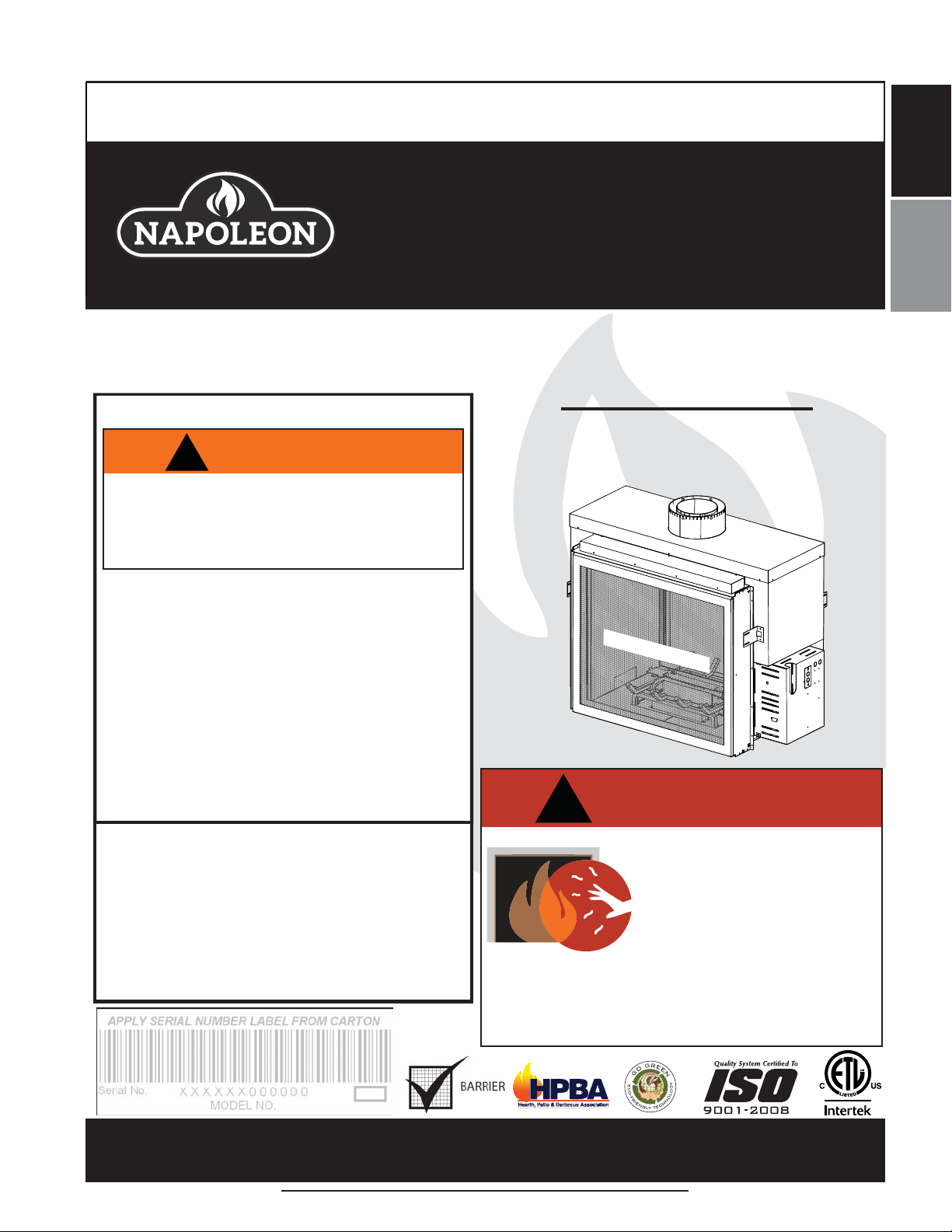
Napoleon HD81NT-1, HD81PT-1 Installation And Operating Instructions Manual
INSTALLER: LEAVE THIS MANUAL WITH THE APPLIANCE.
CONSUMER: RETAIN THIS MANUAL FOR FUTURE REFERENCE.
NEVER LEAVE CHILDREN OR OTHER AT RISK INDIVIDUALS ALONE WITH THE APPLIANCE
INSTALLATION AND
EN
OPERATING INSTRUCTIONS
CERTIFIED TO CANADIAN AND AMERICAN NATIONAL STANDARDS: ANSI Z21.50, CSA 2.22 FOR VENTED DECORATIVE GAS APPLIANCES
HD81NT-1
FOR INDOOR USE ONLY
SAFETY INFORMATION
NATURAL GAS
HD81PT-1
!
WARNING
If the information in these instructions
are not followed exactly, a fi re or
explosion may result causing property
damage, personal injury or loss of life.
- Do not store or use gasoline or other fl ammable
vapors and liquids in the vicinity of this or any
other appliance.
- WHAT TO DO IF YOU SMELL GAS:
• Do not try to light any appliance.
• Do not touch any electrical switch; do not use
any phone in your building.
• Immediately call your gas supplier from a
neighbour’s phone. Follow the gas supplier’s
instructions.
• If you cannot reach your gas supplier, call the
fi re department.
- Installation and service must be performed by a
qualifi ed installer, service agency or the supplier.
This appliance may be installed in an aftermarket,
permanently located, manufactured home (USA
only) or mobile home, where not prohibited by
local codes.
This appliance is only for use with the type of gas
indicated on the rating plate. This appliance is
not convertible for use with other gases, unless a
certifi ed kit is used.
!
A barrier designed to reduce the risk of burns from
the hot viewing glass is provided with this appliance
and shall be installed for the protection of children
and other at-risk individuals.
PROPANE
SAFETY BARRIER
DANGER
HOT GLASS WILL CAUSE
BURNS.
DO NOT TOUCH GLASS UNTIL
COOLED.
NEVER ALLOW CHILDREN TO
TOUCH GLASS.
FR
PG
55
Wolf Steel Ltd., 24 Napoleon Rd., Barrie, ON, L4M 0G8 Canada /
103 Miller Drive, Crittenden, Kentucky, USA, 41030
Phone (705)721-1212 • Fax (705)720-9081 • www.napoleonfi replaces.com • hearth@napoleonproducts.com
$10.00
1.28G
W415-2201 / C / 07.04.19

EN
2
TABLE OF CONTENTS
NOTE: The camera icon indicates video tutorials are available as additional reference,
visit http://mynapoleon.napoleonproducts.com/download/index/44/1
1.0 INSTALLATION OVERVIEW 3
2.0 INTRODUCTION 4
2.1 DIMENSIONS 5
2.2 GENERAL INSTRUCTIONS 6
2.3 GENERAL INFORMATION 7
2.4 RATING PLATE INFORMATION 8
3.0 VENTING 9
3.1 VENTING LENGTHS AND COMPONENTS 9
3.2 TYPICAL VENT INSTALLATION 10
3.3 VENT TERMINAL CLEARANCES 11
3.4 VENT APPLICATION FLOW CHART 12
3.5 DEFINITIONS 12
3.6 ELBOW VENT LENGTH VALUES 12
3.7 HORIZONTAL TERMINATION 13
3.8 VERTICAL TERMINATION 15
4.0 INSTALLATION 17
4.1 WALL AND CEILING PROTECTION 17
4.1.1 HORIZONTAL INSTALLATION 18
4.1.2 VERTICAL INSTALLATION 18
4.2 USING FLEXIBLE VENT COMPONENTS 19
4.2.1 HORIZONTAL AIR TERMINAL INSTALLATION 19
4.2.2 VERTICAL AIR TERMINAL INSTALLATION 20
4.2.3 APPLIANCE VENT CONNECTION 20
4.3 MOBILE HOME INSTALLATION 21
4.4 GAS INSTALLATION 21
5.0 FRAMING 22
5.1 MINIMUM CLEARANCES TO COMBUSTIBLES 24
5.2 HEARTH EXTENSION 24
5.3 STEEL STUD FRAMING KIT 25
5.3.1 INSIDE FRAME ASSEMBLY 25
5.3.2 ATTACH SIDE STUDS (LEGS) 26
5.3.3 ATTACH THE ASSEMBLED FRAME TO THE APPLIANCE 26
5.3.4 INSTALL CONCRETE BOARD SIDE AND CENTER PANELS 27
5.3.5 STEEL FRAMING KIT SIDE TWO 27
5.4 MINIMUM CLEARANCE TO COMBUSTIBLE ENCLOSURES 28
5.5 MINIMUM MANTEL CLEARANCES 30
6.0 FINISHING 31
6.1 SAFETY SCREEN REMOVAL / INSTALLATION 31
6.2 DOOR REMOVAL / INSTALLATION 32
6.3 BURNER INSTALLATION 32
6.4 NON-COMBUSTIBLE FACING MATERIAL 33
7.0 ELECTRICAL INFORMATION 34
7.1 HARD WIRING CONNECTION 34
7.2 OPTIONAL BLOWER INSTALLATION 34
7.3 WIRING DIAGRAM 35
7.4 RECEPTACLE WIRING DIAGRAM 36
7.5 REMOTE RECEIVER INSTALLATION 36
8.0 OPERATION 37
8.1 GENERAL TRANSMITTER LAYOUT 37
8.2 INITIALIZING THE TRANSMITTER/BATTERY HOLDER FOR THE FIRST TIME 37
8.3 TEMPERATURE DISPLAY 38
8.4 FLAME HEIGHT 38
8.5 NIGHT LIGHT DIMMER CONTROL 38
8.6 FAN SPEED 38
8.7 CONTINUOUS PILOT / INTERMITTENT PILOT (CPI / IPI) SELECTION 39
8.8 CHILD PROOF FUNCTION / KEY LOCK 39
8.9 LOW BATTERY / MANUAL BYPASS 39
8.10 SPLIT FLOW 39
9.0 OPERATING INSTRUCTIONS 40
10.0 ADJUSTMENT 41
10.1 PILOT BURNER ADJUSTMENT 41
10.2 FLAME CHARACTERISTICS 41
10.3 RESTRICTING VERTICAL VENTS 41
11.0 MAINTENANCE 42
11.1 ANNUAL MAINTENANCE 43
11.2 CONTROL ACCESS 44
11.2.1 INNER ACCESS PANEL 44
11.3 VALVE REMOVAL 44
11.4 NIGHT LIGHT™ 45
11.5 GLASS / DOOR REPLACEMENT 45
11.6 CARE OF GLASS 46
11.7 CARE OF PLATED PARTS 46
W415-2201 / C / 07.04.19
12.0 REPLACEMENTS 46
13.0 HD81-1 OVERVIEW 47
14.0 ACCESSORIES 48
15.0 TROUBLESHOOTING 49
16.0 WARRANTY 52
17.0 SERVICE HISTORY 53
NOTE: Changes, other than editorial, are denoted by a vertical line in the margin.
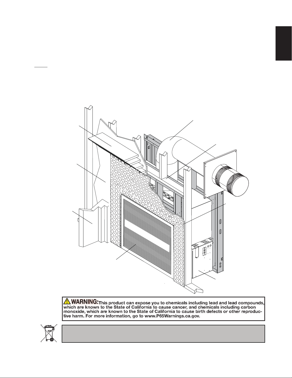
1.0 INSTALLATION OVERVIEW
3
EN
See the section
“FRAMING MINIMUM MANTEL
CLEARANCES”
See the section
“FRAMING - MINIMUM
CLEARANCE TO
COMBUSTIBLE
ENCLOSURES” for
drywall (or other
combustible material)”
See the section
“FRAMING”
Side
Wall
SAFETY BARRIER
See the section
“VENTING - VENTING
LENGTHS AND AIR TERMINAL
LOCATIONS”
See the section
“FRAMING”
See the section
“FRAMING - MINIMUM
CLEARANCE TO
COMBUSTIBLE
ENSLOSURES” for
non-combustible
materials such as tile,
marble, granite, etc.
See the section
“BURNER INSTALLATION”
See the section
“CONTROL ACCESS”
for the control box.
Batteries must be disposed of according to the local laws and regulations. Some batteries may be
recycled, and may be accepted for disposal at your local recycling center. Check with your municipality
for recycling instructions.
W415-2201 / C / 07.04.19

4
2.0 INTRODUCTION
EN
!
WARNING
• THIS APPLIANCE IS HOT WHEN OPERATED AND CAN CAUSE SEVERE BURNS IF CONTACTED.
• ANY CHANGES OR ALTERATIONS TO THIS APPLIANCE OR ITS CONTROLS CAN BE DANGEROUS AND IS
PROHIBITED.
• Do not operate appliance before reading and understanding operating instructions. Failure to operate appliance
according to operating instructions could cause fi re or injury.
• Risk of fi re or asphyxiation do not operate appliance with fi xed glass removed.
• Do not connect 110 volts to the control valve.
• Risk of burns. The appliance should be turned off and cooled before servicing.
• Do not install damaged, incomplete or substitute components.
• Risk of cuts and abrasions. Wear protective gloves and safety glasses during installation. Sheet metal edges may
be sharp.
• Do not burn wood or other materials in this appliance.
• Children and adults should be alerted to the hazards of high surface temperature and should stay away to
avoid burns or clothing ignition.
• Young children should be carefully supervised when they are in the same room as the appliance.
Toddlers, young children and others may be susceptible to accidental contact burns. A physical barrier
is recommended if there are at risk individuals in the house. To restrict access to an appliance, install an
adjustable safety gate to keep toddlers, young children and other at risk individuals out of the room and
away from hot surfaces.
• Clothing or other fl ammable material should not be placed on or near the appliance.
• Due to high temperatures, the appliance should be located out of traffi c and away from furniture and
draperies.
• Ensure you have incorporated adequate safety measure to protect infants/toddlers from touching hot surfaces.
• Even after the appliance is out, the glass and/or screen will remain hot for an extended period of time.
• Check with your local hearth specialty dealer for safety screens and hearth guards to protect children from hot
surfaces. These screens and guards must be fastened to the fl oor.
• Any safety screen, guard or barrier removed for servicing the appliance, must be replaced prior to operating
the appliance.
• The appliance is a vented gas-fi red appliance. Do not burn wood or other materials in the appliance
•
It is imperative that the control compartments, burners and cir
and venting system are kept clean. The appliance and its venting system should be inspected before use and at
least annually by a qualifi ed service person. More frequent cleaning may be required due to excessive lint from
carpeting, bedding material, etc. The appliance ar
gasoline and other fl ammable vapors and liquids.
• Under no circumstances should this appliance be modifi ed.
•
This appliance must not be connected to a chimney fl ue pipe serving a separate solid fuel burning appliance.
• Do not use this appliance if any part has been under water. Immediately call a qualifi ed service technician to
inspect the appliance and to replace any part of the control system and any gas control which has been under
water
.
• Do not operate the appliance with the glass door removed, cracked or broken. Replacement of the glass should be
done by a licensed or qualifi ed service person.
•
Do not strike or slam shut the appliance glass door.
• When equipped with pressure relief doors, they must be kept closed while the appliance is operating to prevent
exhaust fumes containing carbon monoxide, from entering into the home. Temperatures of the exhaust escaping
thr
ough these openings can also cause the surrounding combustible materials to overheat and catch fi re.
• Only doors / optional fronts certifi ed with the appliance are to be installed on the appliance.
• Keep the packaging material out of reach of children and dispose of the material in a safe manner. As with all
plastic bags, these ar
As with any combustion appliance, we recommend having your appliance regularly inspected and serviced as well
•
as having a Carbon Monoxide Detector installed in the same area to defend you and your family against Carbon
Monoxide.
• Ensure clearances to combustibles are maintained when building a mantel or shelves above the appliance.
Elevated temperatures on the wall or in the air above the appliance can cause melting, discolouration or damage of
decorations, a T
• A barrier designed to reduce the risk of burns from the hot viewing glass is provided with this appliance and
shall be installed.
• If the barrier becomes damaged, the barrier shall be replaced with the manufacturer’s barrier for this
appliance.
• Installation and repair should be done by a qualifi ed service person. The appliance should be inspected
before use and at least annually by a professional service person. More frequent cleaning may be required
due to excessive lint from carpeting, bedding material, etc. It is imperative that control compartments,
burners and circulating air passageways of the appliance be kept clean.
e not toys and should be kept away from childr
.V. or other electronic components.
ea must be kept clear and free fr
culating blower and its passageway in the appliance
om combustible materials,
en and infants.
3.2C
W415-2201 / C / 07.04.19
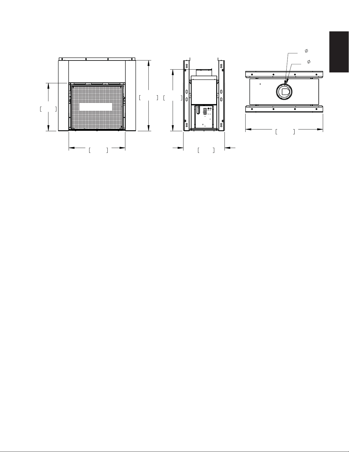
2.1 DIMENSIONS
5
33 7/16"
849mm
SAFETY SCREEN
39 7/16"
1001mm
49 1/4"
1252mm
42 7/8"
1089mm
28 3/4"
730mm
54 1/4"
1378mm
8"
[203mm]
11"
[279mm]
EN
W415-2201 / C / 07.04.19

6
A
2.2 GENERAL INSTRUCTIONS
EN
ALWAYS LIGHT THE PILOT WHETHER FOR THE FIRST TIME OR IF THE GAS SUPPLY HAS RUN OUT,
PROVIDE ADEQUATE CLEARANCE FOR SERVICING AND OPERATING THE APPLIANCE.
NEVER OBSTRUCT THE FRONT OPENING OF THE APPLIANCE.
OBJECTS PLACED IN FRONT OF THE APPLIANCE MUST BE KEPT A MINIMUM OF 48 INCHES
SURFACES AROUND AND ESPECIALLY ABOVE THE APPLIANCE CAN BECOME HOT. AVOID CONTACT
HIGH PRESSURE WILL DAMAGE VALVE. DISCONNECT GAS SUPPLY PIPING BEFORE PRESSURE TESTING GAS
LINE AT TEST PRESSURES ABOVE 1/2 PSIG. CLOSE THE MANUAL SHUT-OFF VALVE BEFORE PRESSURE
TESTING GAS LINE AT TEST PRESSURES EQUAL TO OR LESS THAN 1/2 PSIG (35mb).
USE ONLY WOLF STEEL APPROVED OPTIONAL ACCESSORIES AND REPLACEMENT PARTS WITH THIS APPLIANCE.
USING NON-LISTED ACCESSORIES (BLOWERS, DOORS, LOUVRES, TRIMS, GAS COMPONENTS, VENTING
COMPONENTS, ETC.) COULD RESULT IN A SAFETY HAZARD AND WILL VOID THE WARRANTY AND CERTIFICATION.
THE APPLIANCE MUST NOT BE OPERATED AT TEMPERATURES BELOW FREEZING (32°F / 0°C).
ALLOW THE APPLIANCE TO WARM TO ABOVE FREEZING PRIOR TO OPERATION.
!
WARNING
WITH THE GLASS DOOR OPENED OR REMOVED.
PROVIDE ADEQUATE VENTILATION.
(121.9cm) FROM THE FRONT FACE OF THE APPLIANCE.
WHEN THE APPLIANCE IS OPERATING.
FIRE RISK. EXPLOSION HAZARD.
THIS GAS APPLIANCE SHOULD BE INSTALLED AND SERVICED BY A QUALIFIED INSTALLER to
conform with local codes. Installation practices vary from region to region and it is important to know the
specifi cs that apply to your area, for example in Massachusetts State:
• This product must be installed by a licensed plumber or gas fi tter when installed within the
commonwealth of Massachusetts.
• The appliance damper must be removed or welded in the open position prior to installation of an
appliance insert or gas log.
• The appliance off valve must be a “T” handle gas cock.
• The fl exible connector must not be longer than 3 feet (0.9m).
• A Carbon Monoxide detector is required in all rooms containing gas fi red appliances.
• The appliance is not approved for installation in a bedroom or bathroom unless the unit is a direct vent
sealed combustion product.
The installation must conform with local codes or, in
absence of local codes, the National Gas and Propane
Installation Code CSA B149.1 in Canada, or the National
Fuel Gas Code, ANSI Z223.1 / NFPA 54 in the United
States. Suitable for mobile home installation if installed
in accordance with the current standard CAN/CSA
Z240MH Series, for gas equipped mobile homes, in
Canada or ANSI Z223.1 and NFPA 54 in the United
States.
s long as the required clearance to combustibles is
maintained, the most desirable and benefi cial location for an appliance is in the center of a building, thereby
allowing the most effi cient use of the heat created. The location of windows, doors and the traffi c fl ow in the
room where the appliance is to be located should be considered. If possible, you should choose a location
where the vent will pass through the house without cutting a fl oor or roof joist.
www.ncertied.org
We suggest that our gas
hearth products be installed
and serviced by professionals
who are certied in the U.S.
by the National Fireplace
®
Institute
(NFI) as NFI Gas
Specialists
If the appliance is installed directly on carpeting, vinyl tile or other combustible material other than wood
fl ooring, the appliance shall be installed on a metal or wood panel extending the full width and depth.
Some appliances have optional fans or blowers. If an optional fan or blower is installed, the junction box must
be electrically connected and grounded in accordance with local codes, use the current CSA C22.1 Canadian
Electrical Code in Canada or the ANSI/NFPA 70 National Electrical code in the United States.
The optional heat circulating blower is supplied with a cord.
This appliance is equipped with a power back up control system. Therefore four 1.5 volt “AA” batteries are
required for the battery holder. Use alkaline batteries only. See “IN THE EVENT OF A POWER FAILURE”
section.
W415-2201 / C / 07.04.19
4.1C

2.3 GENERAL INFORMATION
FOR YOUR SATISFACTION, THIS APPLIANCE HAS BEEN TEST-FIRED TO ASSURE ITS OPERATION
AND QUALITY!
Altitude (FT) 0-4,500 0-4500
Max. Input (BTU/HR) 60,000 50,000
Max. Output Steady State (BTU/HR) 38,753 33,677
Effi ciency (w/the fan on) 64% 68%
Min. Inlet Gas Supply Pressure 4.5" w.c. (11mb) 11" w.c. (27mb)
Max. Inlet Gas Supply Pressure 13" w.c. (32mb) 13" w.c. (32mb)
Manifold Pressure (Under Flow Conditions) 3.5" w.c. (9mb) 10" w.c. (25mb)
This appliance is approved for bathroom, bedroom and bed-sitting room installations and is certifi ed for
mobile home installation.
This appliance is only for use with the type of gas indicated on the rating plate. This appliance is not
convertible for use with other gases, unless a certifi ed kit is used.
When the appliance is installed at elevations above 4,500ft (1371m), and in the absence of specifi c
recommendations from the local authority having jurisdiction, the certifi ed high altitude input rating shall be
reduced at the rate of 4% for each additional 1,000ft (305m).
The switch on the battery holder must be placed in the middle position. If this switch is not in this
position the appliance will not operate using the remote, see “REMOTE RECEIVER INSTALLATION” and
“CONTROL MODULE REMOVAL” section.
Expansion / contraction noises during heating up and cooling down cycles are normal and are to be
expected. Change in fl ame appearance from “HI” to “LO” is more evident in natural gas than in propane.
NOTE: The protective wrap on plated parts is best removed when the assembly is at room temperature
but this can be improved if the assembly is warmed, using a hair dryer or similar heat source.
This appliance is equipped with a remote control system, which requires batteries (supplied) to be installed.
The transmitter takes 3 “AAA” batteries and in the case of a power failure the battery back-up takes four
“AA” batteries.
7
EN
HD81-1
NG P
65%
HD81-1
W415-2201 / C / 07.04.19

8
NG THE APPROPRIATE
TALLATION MANUAL
NSTALLATION AND
AFTER SERVICING THE VENT-AIR
AKE SYS
USE AS A HEATING APPLIA
L'A
LÉVATION
MENTATION
ALIMENTATION RÉDUITE
MN
ANIFOL
NE D'E
PRESS
R COLUMN
MINIM
NNE D'EAU
PRESSIO
COLUMN
AXIMUM
NE COLONNE D'EAU
PRESS
A NORM
UNIS DE L
3280. DANS LE C
AU CRITÈRE DE MES
MANUFACTURÉS, LES SIT
W010-3441. SUIVEZ LES IN
4001657 (NGZ)
4001659 (WUSA)
P5%P4:
PROP
NT
N
LISEZ LELISEZ L
CET APPAREIL EST MUNI
PPAREIL EST MUNI
AUTOMATIQUEMENT. NTIQUEMENT. N
. OUVRE LA PORTE VIT OUVRE LA PORTE VI
6. TOURNEZ LA SOUP. TOURNEZ LA SOU
DERRIÈRE LE PADERRIÈRE LE
7. ATTENDEZ CI7. ATTENDEZ C
ODEUR DEODEUR DE
N’Y A PAN’Y A PA
8. TOUR8.
9. FER9.
TO TURN
2.4 RATING PLATE INFORMATION
Both the rating plate and operating instructions are riveted to the bottom of the side spacers. There is a hole
EN
in the bottom of each mounting plate to help with rotating the plate up.
SIDE SPACERS
R
CERTI
E
NO
F
E
F
W
R
T
OR
/
EN
F
N
C
V
I
F
ENTED
E
1
ERTIFIE
C
C
O
60
D UNDER /
USE
E
A
W
N
R
61
N
#
O
/
ARNI
F
CS
T
U
T
O
HEAP
G
AP
SONI
CO
S
Y
A
A
WI
ER
Z24
S
E
C
TH
PL
D
NT
ON
F
TH G
N
SÉCURIT
WI
WI
PLI
D
A
I
IC
N
HOM
A
WIT
R
0
G
T
E
S
ST
M
CT
EPLA
MINI
A
TH
C
TRU
AN
S
TH
H
B
:
ALLA
MA
U
HA
THE
LE
WIT
DO
SE
OLOG
H
PPL
L
C
T
MUM
C
E,
C
UF
US
AS
SOLI
T
OP
R
É
T
T
H
EHE
NOT
F
E
TI
I
I
W
IO
A
E
FA
CO
T
E
L
HIS
R
E
O
P
S
S
SID
H
D
O
N
H
TH
CL
I
UE
N
P
GE
GAS
A
I
OR 0
NT
E
A
BY
CH
ADD
D
BACK
L
DOO
D
CO
L
TE
FLAMES
E
I
E
E
A
R
UNIT ON
E
S:
AU GAZ
S
SE
T
T
WIL
N
MA
FUEL.
E
STANDA
R
O
A
0
N
A
HE
E
C
L
F
.
P
FO
R
0
L
QUI
AP
RAMI
N
E
,
I
'
SI
L
RS
O
A
S
I
S
Y
.
N
M
R
O
EE
C
NCE
N
P
C
D
A
P
M
M
*
,
NS
A
O
R
EN
P
E
N
OTH
M
LES N
AT
E
N
O
O
ME
R
V
H
ED
S
U
AX
G
0
AU
E
D F
V
MAN
DI
WN
&
O
E
FA
L
T
MA
C
ED F
M
R
R
ER
I
E
MOBIL
Y.
I
O
N
X
MU
BAC
C
O
I
A
ÉV
I
E
S
A
Z
P
NU
T
TER
E
OR
UF
C
R
R
E
R
ONT
L
T
MODE
O
U
A
O
XIG
M
A
E
S
EC
OMB
HAN
FI
U
T
K: PER S
R
A
A
C
V
R
ND
H
ME
O
O
MA
R
R
I
E
E
E
L
C
U
B
A
A
ESSE
E
ORI
M
W
E
LE
R
N
ESA
T
A
FOR
HO
LS
L
N
ED
MAX
L
U
NUAL
A
T
T
S
N
US
E
C
EC
ION
R
N
S
: CSA
ER'
.
ZO
MES,
E
R
MA
ÉES
F
TL
I
D
FE
T
S
OO
T
GRE
N
O
IMU
L N
T
NT
W
.
S
I
R
DE
E
DE
XI
S
AN
BLE
R FI
T
H
I
T
IN
M
,
M
O
C
Y
A
M
OM
I
2
M
A
PTH
TI
A
N
D OFF
A
,
2
L
A
L
ST
CR
LF
A
B
LL
NI
TE
.3
A
T
DE
L
V
A
C
EX
L
O
R
A
ENT
R
SH
3
R
AN
E:
A
I
N
TURA
R
L
S
TH
T
E
I
UCT
b
GAZ N
T
25
TI
A
OR
OG
TE
E
2
N
E
ENS
IN
2
TING:
SP
A
O
-
R
RO
C
X
4 CF
2008
"
L
"
D
G
EL
M
I
NS
U
T
.
"
I
A
EN
ANADA
A
O
A
EN
É
S
OM
E
15
ION
M
O
F
CE
N
EE
L
DA
R,
POU
3
GT
CA
A
OR
"
1
T
SIONS
R
.
M
TE
,
*
1
5
L
AN
RS
D
S
/
5
"
A
I
H
NS
A
N/
IN
NS
A
L'
V
M
E
.
R
W
S
NS
N
B
R
GAS
/
DB
CSA
C
F
4
EXT
AN
I
.
TH
0
U
A
F
TURAL
TR
A
L
I
.
A
O
T
.
N
5
A
T
.
AL
8
E
L
I
I
"
R
Z2
RRI
E
E
E
B
ON 32
U
S
2A
U
S
S MA
EN
W
R
HD8
#
D
R
T
Z
F
FO
C
U
3
7.
A
24
A
-S
MP
I
A
C
1
T
NIT
Q
5
E
0
S
0"
L
C
TE
.88
:
ION
OL
I
/
0
,
R
U
IO
LA
TTI
4
I
,
T
L
8
ON
M
S
60H
M
É
W
5
R
ED
U
OGS,
1NT
0
N
UM
ONS
0
b
HS
TIO
.
A
A
R
NG
C
I
0F
- 2
N
D
TE
U
T
E
OLU
S
N
Z
I
ANSL
A
T
TH
C
D
ÉR
N
M
T
/
008 V
M
6
ROO
R
GL
D'U
A
HOM
R
(
N
UM
0
AN
D
0
E
T
I
C
,0
M
A
IO
APO
-
E
22,
AN
A
1
E
O
N
NU
AP
0
N
AD
3
S
S
DE
M
, CAN
0
E CAS
L
E
/
7
0
S
S
D
E
E
U
0
THEM
B
0
P
F
R
L
A
C
I
,
'
MA
M
N
0
NS
UN
M
U
FOR
AC
T
L
INST
EO
B
ESEAL
O
N
U/
)
I
B
TE
N
U
A
L
T
E
E
T
TUR
/
N
R
H
O
I
NC
D
A
S
AD
U
C
O
D
N
A
C
VE
N
'
ANU
LLA
V
ON
UN
/
U
O
H
ER
LL
GAS F
H
N
E
E
É
I
N
L
A
CET
A
ED'E
N
NT K
E
MU
S
S,
A
O
S
T
T
MB
G
F
R
T
C
I
N
ION
M
A
N
I
E
L
I
OL
ST
NE
T
ONS
S
OB
C
D
E
GS
RE
A
I
E
T
A
T
S
U
NE
.
I
U
O
S
REPLACE
BE
UR
L
NORM
D
C
IL
S
S
NN
À
P
T
.
,
'E
U
I
E
C
E
ITES
N
SE
IT
EC
S
E
COUC
D
I
V
A
S É
E
P
T
E
I
U
D
T
ENTED U
U
A
SSAR
U
I
E
I
D
N
D
F
E
BL
T
H
E
QU
E
P
OWN
IC
'
S
E
E
ORI
D
O
/ALIMENTA
U
T
/
A
A
E
H
S
M
T
É
'ÉT
IPÉ
U
L
.
ND COM
Y
E
FO
L
E
FI
/
PR
H
E
R,
ER
M
É
AFTER S
AL
P
C
A
C
P
S CO
ES
E
V
S
R
A
R
T
M
R
E
OPER
UNE
O
A
S
ATER /
IN
IM
N
ESSIO
S-U
ES
M
IN
T
NS
/
A
I
S
I
G
E
F
IO
I
NS
OBI
N
I
U
M
P
M
OL
S
N
E
M
S
NI
T
T
THE
J
M
N
RE
I
MUNA
G
T
U
T
I
RE
O
R
E
U
R
O
A
A
S
AT
ER
D
L
A
N
M
AZ
CT
U
N
N
S
N
L
X
E
IA
L
N
A
P
AU
C
I
S
I
LE D
SU
IN
IM
D
APP
V
O
L
TIE
,
E
E
HOM
R
P
T
I
EN V
'
IC
A
O
L
N
U
AL
STA
E
U
UTÉS
ION
P
P
P
C
TION
N
R
S
S
I
M
R
A
E
P
N
NG
O
R
E BA
IME
S
,
MODEL
D'
ÉDU
L
UT
E
RE
S
O
L
L
A
U
UM
Y
A
I
A
L
GU
U
LA
PR
INS
N
R
PR
,
TH
N
I
N
HD8
EC
M
L
P
N
ÊTR
A
I
SI
E
0-45
IN
D SA
I
T
L
I
TI
P
T
T
AN
M
E
NS
I
A
E
BER/NO.D
/
A
T
ESS
T
E
A
L
/
E
U
DE CHAU
O
EN
T
5
A
N
T
Y
EU
VE
KE
E
0
R
0
I
UA
I/
N
T
L
E
ON
PRESS
,
1P
F
0
N
F
0
T
1
APPLI
L
U
R
A
F
AN
U
N
P
E
A
0
6,0
FP
A
L
S
R
T
U CAN
A
0B
N
T-A
T
T
M
#
TIO
YSTEM
T
E
I
(0-
D
Y
A
0
5
5
PRO
ON M
I
S
N
0
3
/
0
T
#52
I
S
L
T
5
1
B
:
R
I
N I
QU
U
1
U
M
01A
'
U
T
3
L
A
A
TU
R
F
/
D
A
7
1
A
D
O
H
A
I
P
F
.
E
FAGE
0
A
É
0
'
ND
L
N
I
D
G
É
.
/
P
M
O.
"
D'
.
H
E
INST
X
/
E
SI
E
V
AR
A
S
P
W
)
,
I
INS
ARD,
M
ACU
SE
OU
P
AP
D
/
A
1
ANE
SÉ
AL
R
EI
E
1
T
ALL
R
É
"
T
P
E
ALI
L
#
R
E
E
A
A
AT
C
W
R
5
R
S
É
RIE:
TITL
DOI
S
LL
UX
4
I
O
AT
SE.
1
Y
E
FÉRER
C
CE
IO
M
O
3
P
ST
D
OL
ATIO
"
E
U
R
T
N
É
ENTÉ
E
L
IN
W
R
I
É
T
I
TATS
PRO
ÉV
U
L
LE
É POU
SI
2
ME
AT
C
M
AC
HD
E
4
N
A
OL
D
R
N
A
ST
E
CF
DE
E
C
DE
/
C
P
-U
L'É
R
D
AU G
L
UM
UE
G
8
O
RE
R
I
A
'
R
CO
N
U
M
L
P
1
R
,
V
P
N
I
N
R
N
A
I
P
RO
S
P
D
N
EN
UN
R
A
LUMN/ D'U
EC
S
O
/
O
S
AR
DE
D
A
S
IS
AZ ET VEN
NA
S
R
R
E
'
P
NC
T
T
U
P
,BUR
ED
M
O
T
S
T
A
R
N
L
A
AN
AS ÊTRÉ U
P
COMBUSTI
L
E
L
IÉ
3
E
GA
E
PR
A
O
APP
O
L
280
'
COLONNE D
R
A
T
W
A
T
L
NNE D'E
NORME
AIRE P
N
E
IR.
È
Z
DE B
TI
E
I
P
LA
E
TH
S
.
N
ON.
EN
ON D
WH
R
OR
E
AV
A
T
S
TH
UTI
C
T
IVE
RÉFÉR
R
I
O
E
E
O
E
I
O
A
L
T
A
N
E
IR
DE
E
NR
L
ULEM
U
U
É
L
NS
A
E
O
A
CU
T
IL
R
ISA
ASS
U
S
N
HIS
'
S
V
E
É
UN
L
T
BLE
N
A
.
RRENT
E
A
CRI
I
E
'
ERT
N
N
É
ED
ILIS
P
CUR
V
U
U
URÉ
R
EN
US
S
T
V
P
E
ITRÉES
TIL
L
T
T
ACU
A
A
ENT
'
C
A
MA
EA
È
REI
UM
'
C
S
ITÉE
ENSE
SOL
ELU
LLER E
R
I
É
LE
T
P
O
SS
S
U
E D
I
ISER
A
A
AR
A
S
N
L
TA
AN
T
M
DÉGAGE
N
O
T
IQ
AUCU
A
I
T
DA
V
E
EM
ON
ACT
N
N
MB
A
L
CO
U
IDE
VE
D
DA
UIE
EC C
M
E
IN
M
T
EL
R
E
D
L
HOMOLO
E
F
OBI
TI
M
A
D
ENT
ESS
RD
E
AVE
S
ABR
C
N
P
S
E
B
VECLES
UR
IS
NE
MATÉ
L
T
N
C
L
U
CÔ
A
FOU
M
US
E
C
E
ES
DU
I
ST
N
:
C
ETTE
SI
LE
EN
A
T
T
C
A
D
RR
N
E
IBL
D
HE
R
D
N
R
S
O
TS MIN
S
'
E
AJOUT
E
IA
T
NI
I
D
.
ÉR
F
R0
SSUS,
IT
0
ES:
U
G
E
L
AV
U
S
DE
AMM
E
D
UÉE
E
PR
0
É
E
M
L
N
0
E
G
V
C
O
I
A
C
MAUX D
A
Z P
*
ITÉ.
A
ES
N
ÉV
T
O
C
M
L
N
OF
G
É
TÉS &
E
L
S
'
A
EX
T
R
A
E
AUTRE
E
T
E
U
ONDEU
M
I
S
E
A
P
NT
A
M
A
T
M
E
NTR
L
UX
A
E
NTEA
P
ANUE
NT P
DE
U
A
ARR
NSI
P
C
S
N
E
D
AR
E
UE
E
S
CL
P
G
E
ON
Q
T
O
R
RD'E
RO
M
R
U
E
L
I
FINITI
U
L
È
U
A
A
IL
H
D
D
E
R
A
R
SS
P
N
E
E:
O
'
R
TÉRIA
DE
I
L
NS
N
P
IF
I
R
E
O
É
SE
C
RO
I
S
S
T
I
Z
N
T
C
ASTRÉ
A
.
O
L
M
R
.
RÉ
A
P
IRE
O
N
UCT
A
T
R
U
N LE
TAL
T
I
F
IÉT
O
É
X
.
É
N
R
I
R
O
AI
E
I
:
S
ER
A
2
N
1
M
R
U
ES
1
5"
P
E
A
A
2"
X
5
O
X
V
P
P
U
D
U
I
A
OU
0
MAL
15
'O
RD
MAN
C
.
8
S
"*
E
R
2A
S
U
E
E
L
A
U
R
S
:
E
M
TUR
E
S
EXT
S
2".
P
L
,
D
60HZ
E
R
EN
'I
N
É
S
F
SI
T
É
O
A
R
N
L
E
L
S
R
A
TI
O
W
N
38
5
04
19
RATING
PLATE
PROPANE MODEL
HD81PT
TION DANS UNE CHAMBRE À COUCHER, UNE SALLE DE BAIN ET
UN COMBUSTIBLE SOLIDE NE DOIT
PAS ÊTRÉ UTILISÉ AVEC CET
APPAREIL. UTILISER AVEC LES
PORTES VITRÉES HOMOLOGUÉES
SEULEMENT AVEC CETTE UNITÉ.
AVERTISSEMENT: N'AJOUTEZ PAS A CET
APPAREIL AUCUN MATÉRIAU DEVANT ENTRER
EN CONTACT AVEC LES FLAMMES AUTRE QUE
CELUI QUI EST FOURNI AVEC CET APPAREIL
PAR LE FABRICANT.
DÉGAGEMENTS MINIMAUX DES MATÉRIAUX
COMBUSTIBLES:
DESSUS 0 PROFONDEUR D'ENCASTRÉ 25"
PLANCHER 0 ÉVENT 2"
CÔTES 0 MANTEAU 16" *
ARRIÉRE 0
DESSUS, COTÉS & ARRIÈRE: SELON LES ESPACEURS
DE DÉGAGEMENT POUR LES MATÉRIAUX D'OSSATURE
SELON LE MANUEL DE PROPRIÉTAIRE POUR LES
MATÉRIAUX DE FINITION.
* L'EXTENSION HORIZONTALE MAXIMALE: 2". RÉFÉRER
AU MANUEL D'INSTRUCTION POUR DES EXTENSIONS
PLUS GRANDES. RÉFÉRER AU MANUEL D'INSTALLATION
DE PROPRIÉTAIRE.
CLASSIFICATION: 115V 0.82AMP, 60HZ
GAZ VENTILÉ. HOMOLOGUÉ POUR INSTALLA
FOYER À
UN STUDIO. APPROPRIÉ POUR INSTALLATION DANS UNE MAISON MOBILE SI SON INSTALLATION CONFORME AUX
EXIGENCES DE LA NORME CAN/CSA Z240MH SÉRIE DE MAISONS MOBILES ÉQUIPÉES AU GAZ, EN VIGUEUR AU CANADA
OU AUX ÉTATS-UNIS DE LA NORME DE SECURITÉ ET DE CONSTRUCTION DE MAISONS MANUFACTURÉES, TITRE 24 CFR,
SECTION 3280. DANS LE CAS OU CETTE NORME D'ÉTATS-UNIS NE PEUT ÊTRE APPLIQUÉE, SE RÉFÉRER A LA NORME
RELATIVE AU CRITÈRE DE MESURES DE SÉCURITÉ CONTRE L'INCENDIE POUR LES INSTALLATIONS DANS LES MAISONS
MANUFACTURÉS, LES SITES ET LES COMMUNAUTÉS, ANSI/NFPA 501A. POUR UNE UTILISER SEULMENT AVEC
BARRIÈRE W010-3441. SUIVEZ LES INSTRUCTIONS D'INSTALLATION SE TROUVENT DANS LE MANUEL D'INSTALLATION.
P4:65%
L'APPAREIL DOIT ÉVACUER SES GAZ EN UTILISANT L'ENSEMBLE
D'ÉVACUATION PROPRE A NAPOLEON. RÉFÉRER AU MANUEL
D'INSTALLATION DE PROPRIÉTAIRE POUR L'ÉVACUATION
PRÉCISE. IL EST IMPORTANT DE BIEN RÉINSTALLER ET
RESCELLER L'ÉVENT APRÈS AVOIR ASSURÉ LE MAINTIEN DU
SYSTÉME DE PRISE D'AIR.
PRODUIT DÉCORATIF: NE PAS UTILISER COMME APPAREIL DE
CHAUFFAGE.
W385-1991 / A
WARNING: DO NOT TURN ON IF CHILDREN OR OTHER AT RISK INDIVIDUALS ARE NEAR THE FIREPLACE. AVERTISSEMENT : NE PAS ALLUMER SI DES ENFANTS OU D’AUTRES INDIVIDUS À RISQUE SONT À PROXMITÉ
1. STOP! READ THE ABOVE SAFETY INFORMATION ON THIS LABEL.
2. REMOVE THE BATTERIES FROM THE TRANSMITTER.
3. TURN OFF ELECTRIC POWER TO THE FIREPLACE.
4. THIS FIREPLACE IS EQUIPPED WITH AN IGNITION DEVICE WHICH AUTOMATICALLY LIGHTS
THE PILOT. DO NOT TRY TO LIGHT THE PILOT BY HAND.
5. OPEN THE GLASS DOOR.
6. TURN MANUAL SHUTOFF VALVE CLOCKWISE TO OFF. LOCATED BEHIND THE
ACCESS PANEL.
7. WAIT FIVE (5) MINTUES TO CLEAR OUT ANY GAS. IF YOU SMELL GAS INCLUDING NEAR
THE FLOOR, STOP! FOLLOW “B’ IN THE ABOVE SAFETY INFORMATION ON THIS LABEL. IF
YOU DON’T SMELL GAS, GO TO THE NEXT STEP.
8. TURN MANUAL SHUTOFF VALVE COUNTER-CLOCKWISE TO ON.
9. CLOSE THE GLASS DOOR.
10. TURN ON ALL ELECTRIC POWER TO THE FIREPLACE AND RE-INSTALL BATTERIES INTO
THE TRANSMITTER.
11. PUSH THE ”ON” BUTTON ON THE TRANSMITTER. YOU SHOULD HEAR AN AUDIBLE BEEP
FROM THE RECEIVER WHICH INDICATES COMMUNICATION. (REFER TO FIREPLACE
OPERATIONS FOR REMOTE ACTIVATION).
1. TURN OFF ALL ELECTRIC POWER TO THE FIREPLACE IF SERVICE IS TO BE PERFORMED.
2. ACCESS DOOR INSIDE THE FIREBOX MUST BE REMOVED TO ACCESS THE MAIN SHUTOFF VALVE.
3. TURN MANUAL SHUTOFF VALVE CLOCKWISE TO OFF. DO NOT FORCE.
LIGHTING INSTRUCTIONS / INSTRUCTIONS D’ALLUMAGE
DU FOYER.
1. ARRÊTEZ! LISEZ LES RECOMMENDATIONS DE SÉCURITÉ DE CETTE ÉTIQUETTE.
2. RETIREZ LES PILES DE LA TELECOMMANDE.
3. COUPEZ L’ALIMENTATION ÉLECTRIQUE À L‘APPAREIL.
4. CET APPAREIL EST MUNI D’UN DISPOSITIF D‘ALLUMAGE QUI ALLUME LA VEILLEUSE
AUTOMATIQUEMENT. N’ESSAYEZ PAS D‘ALLUMER LA VEILLEUSE MANUELLEMENT.
5. OUVRE LA PORTE VITRÉE.
6. TOURNEZ LA SOUPAPE DE SECTIONNEMENT MANUELLE VERS LA DROITE À “OFF”. SITUÉ
DERRIÈRE LE PANNEAU D’ACCÉS.
7. ATTENDEZ CINQ (5) MINUTES POUR QUE LE GAZ PUISSE S’ÉCHAPPER. SI VOUS DÉTECTEZ UNE
ODEUR DE GAS, ARRÊTEZ! ET OBSERVEZ L’ITEM “B” DES MESURES DE SÉCURITÉ CI-DESSUS. S’IL
N’Y A PAS D’ODEUR DE GAZ, PASSEZ À L’ÉTAPE SUIVANTE.
8. TOURNEZ LA SOUPAPE DE SECTIONNEMENT MANUELLE VERS LA GAUCHE À “ON”.
9. FERMEZ LA PORTE VITRÉE.
10. TOURNEZ L’INTERRUPTEUR DE L’APPAREIL ET L‘INTERRUPTEUR À DISTANCE MURAL À “ON” ET
REPLACEZ LES PILES.
11. APPUYEZ SUR LE BOUTON «ON» DE LA TÉLÉCOMMANDE. VOUS DEVRIEZ ENTENDRE UN «BIP»
DU RÉCEPTEUR VOUS INDIQUANT QUE LA COMMUNICATION EST BONNE. (POUR ACTIVER LE
RÉCEPTEUR. RÉFÉREZ-VOUS À LA SECTION FONCTIONNEMENT DU FOYER).
TO TURN OFF GAS / INSTRUCTIONS POUR COUPER LE GAZ
1. COUPEZ L’ALIMENTATION ÉLECTRIQUE AU FOYER SI UN TRAVAIL D’ENTRETIEN DOIT SE FAIRE.
2. POUR ACCÉDER À LA SOUPAPE D’ARRÊT MANUELLE, ENLEVEZ LA PORTE D’ACCÈS SITUÉE À L’INTERIEUR DU FOYER.
3. TOURNEZ LA SOUPAPE D’ARRÊT MANUELLE VERS LA DROITE À « OFF ». NE FORCEZ PAS.
W385-0439 / D
1
.
2
.
S
T
3
.TUR
O
R
P
4
E
!
.
MO
READ
VE
T
N
H
5
.
I
T
O
D
S
THEA
H
6
O
FF
F
.
E
O
I
N
R
B
ELEC
PEN
O
EPLACE
A
B
T
T
TTERIESF
O
U
7
TR
.W
V
R
P
T
TRI
E
AN
HE GLASS
N
Y
T
SA
C
M
EL
O
I
A
S
A
F
P
S
I
.
L
T
ET
NUA
O
EQUIPPED
T
8
IG
R
W
.
OP
F
T
O
Y
HT
I
ER
OTHE
V
9
M
IN
L
!
.
D
E(5)
T
F
T
TH
OO
F
S
UR
T
10
OLLO
HE
OR
O
H
C
E
.
R
N
U
L
THE
NEX
PILO
M
M
T
.
T
O
WITH
MAN
T
IN
R
A
W
O
S
U
1
A
TION
U
1.P
F
E
T
R
FIREP
N
TR
“B
F
T
TES
THE GL
ST
U
N
S
”
A
BY
AN
A
M
V
IN
N
E
O
ON
L
A
ITTE
U
P
T
S
H
N
L
IG
S
THE
L
SH
.
O
R
V
M
A
A
H
THIS
N
E
A
E
C
N
A
U
IT
CLEAR
R
I
C
THE
L
ACT
E.
SS D
T
D
T
A
.
T
C
L
E
ION
O
.
E
B
L
I
VE
LI
E
F
L
O
R
O
IV
A
“O
F
L
.
V
O
C
GH
B
A
D
R
E
OUTA
V
E
OR
N”
KWI
TI
EL
E
WH
C
AL
S
V
ON
T
B
A
.
.
V
TIN
ICEW
R
U
F
SE
E C
I
C
)
I
ETY
T
C
N
HIND
T
G INST
OU
Y
ON
PO
H
I
GA
N
I
NTER-CLOC
C
W
ONTHE
F
ICA
H
S
O
E
.
AU
RM
R
T
I
FY
E
RUC
TO
T
T
S
A
O
O
T
OU
TRANS
C
M
I
ON
O
O
T
A
H
K
F
MM
TICALL
TIONS
S
WISE
F
E
O
M
1
.L
.
N
UNI
ELL
M
F
2
I
THIS
I
O
R
TT
.
C
Y
TU
C
E
GAS
3
A
E
P
A
.
LIGH
R
TION
/
R.
A
T
L
L
N
CCE
I
EDB
A
A
NSTR
O
B
IN
T
Y
C
TS
U
EL
F
OU SH
.
E
CL
(REF
T
SS
R
F
O ON
E
.
N
A
A
TH
U
I
H
LL
DOOR INSIDE
F
N
DIN
MA
I
E
UC
D
Y
N
E
ER
O
O
D
.
PI
N
L
U
R
G
U
E
U
L
T
L
TIONS
T
E
C
A
OT
N
O
D
D
HE
-
T
L
I
E
H
ON’
N
R
F
.
AR
S
IR
I
EA
S
A
C
H
1
T
T
.
C
E
U
POWER
R
A
THE
TH
S
PL
C
T
2
L
O
M
AN
D’ALL
E
.
EF
L
ARRÊTE
ACE OP
F
S
ELL
3
F
BA
S
F
A
.
IR
R
L
VA
U
T
O
E
4
E
TT
GA
DI
O
.
B
L
M
O
C
V
O
B
E
UM
THE
R
O
O
S
ERA
E
Z
X
L
R
,
V
U
C
!
G
E
C
M
I
E
P
5
L
E
E
O
F
L
B
US
AGE
TIO
.
I
E
T
THE
S
Q
O
S
I
EE
RE
Z
E
6
AP
C
U
TB
IN
L
.
ZL
N
KWIS
E
O
P
P
’A
B
P
S
MEN
LA
E
T
U
F
L
A
E
A
O
F
V
R
T
I
R
R
C
ME
S
T
OR
O
REZ
7
E
O
E
EI
E
T
T
.
R
T
UR
M
M
C
E
N
HE
.
I
L
ECO
F
O
A
R
RI
N
T
THE
SER
LA
E
N
V
T
E
AT
A
’
E
ESS
S
E
E
E
T
M
S
TM
PO
D
D
Z
MM
TE
I
OTE
O
OD
FR
V
BEHI
LA
T
A
8
N
IC
O
N
UN
RTE
AND
.
Y
TO T
É
EU
S
O
S
D
E
T
A
E
’I
9
O
L
O
E
M
C
I
I
Z
L
.
S
ND
EC
R
U
Z
T
C
D’U
N’
A
O
V
P
THE
T
O
P
1
E
C
TIONS
DE
FF.
AS
ITRÉ
T
O
AP
0.
U
S
Y
U
T
INQ
F
R
N
S
R
B
H
E
DO
A
D’ALL
I
RN
E
GA
Q
TRA
E
N
DI
E
T
R
T
P
E
H
D
U
E
P
M
(5)
ACC
O
AS
SPO
1
.
Z
Z
E
E
ES
D
ER
1
NO
EZ L
U
,
R
N
OFF
.
M
ES
L
À
M
D’
R
A
UM
EPLAC
S
F
A
E
A
ESS
T
S
INUTES
L
N
R
O
M
A
C
N
OD
SO
’
É
AP
I
F
E
A
R
R
T
PP
ITTE
E
U
T
O
CUR
P
Z
ÊTE
M
I
«
RL
I
A
FD’AL
E
U
O
R
P
GAS / INSTRUCTIO
P
O
E
U
L S
L
U
C
P
A
N
A
E
B
’
D.
R
Y
I
R
A
A
R
E
N
R
ACTIVER
N
Z
N
I
I
Z
TE
E
HU
P
T
.
PE
.
POU
LES PI
TER
E
!
V
E
E
DE
É
»
Z
I
E
EI
M
L.
L
L
S
TO
V
D
T
U
D
.
DE SECTIO
E
L
ITR
U
GAZ,PAS
E
R
R
U
M
FF
N
L
OB
R
U
E
CETT
T
AGE
Q
RÉ
L
L
É
PTEUR
U
V
M
SER
U
E
L
E.
AL
E
SE
A
E R
C
E
S
B
N
V
E
.
Q
L
E
V
OU
M
E
UE
PTE
E
ÉTIQUE
U
É
E
S
.
A
CEP
N
I
G
Z
E
D
LL
T
N
A
N
A
Z
O
EL
U
UELLE
L
LL
E
E
Z
’
R
N
À
ITE
TEU
M
V
U
PUISSE
’
«
A
V
L
EN
E
M
’É
T
P
OUS IND
M
O
R
NS
E
TE.
P
R
T
MENT.
T
S
N
“
AR
A
,
L
B
RÉ
L
M
PE
»
A
”
A
DE
EI
ANU
P
1
DES
S’É
VEILL
D
.
F
S
L
O
R
ÉRE
I
2
U
E
Q
L
C
O
UR
.
E
I
A
T
C
U
V
H
M
I
L
T
3
E
ANTE
O
T
APPER.
A
L
L
Z
ESURE
.T
E
USE
’INTER
E
ÉL
U
-
N
P
V
C
O
P
T
V
O
É
U
E
QU
O
ERS L
U
R
C
Z
.
O
AUT
L
S
O
UPER LE
A
U
S
R
E L
CC
’A
SI
M
R
À L
U
D
L
N
O
MA
V
É
A
I
P
A
E
E
M
M
D
A
OU
TEUR
C
À
Z
GA
E
E
SEC
NDE.
S
A
L
R
N
O
TI
É
“
S
A
UC
T
O
À
C
MM
-
SOU
A
D
F
L
U
TI
T
A
H
À
F
É
VO
R
I
S
U
O
O
”
E
G
T
I
DIS
.
O
N
N
TÉ
PAP
E
N FON
U
U
AZ
É
I
C
C
L
L
S DEV
P
T
TE
LE
O
O
C
A
A
E
AN
P
TION
I
-
-
-
C
D
E
Z
DESSUS
CTION
T
C
’A
D
U
À
RI
RIE
E
’A
RR
N
R
Q
E
“
M
E
O
RÊ
U
Ê
S
Z EN
U
N
T
E
T
N
R
TM
”
M
.
A
E
B
.
A
U
ANUEL
MENT
AN
ONNE.
L
T
F
E
À
U
O
N
E
“
Y
D
O
L
ER
L
R
L
D
N
E
(
E
EU
U
P
,
”
SI
E
V
OUR
E
F
N
ER
T
U
N
L
O
E
N
Y
S
V
E
E
T
L
ZL
RA
R
A
.)
DROI
A
VA
P
I
O
L
R
D
TE À
T
’E
E
N
D
’
T
A
«
R
C
O
E
C
F
T
È
F
IE
S
»
SI
N
.
T
N
D
U
E
O
É
F
E
I
T
ORC
À
S
L
E
’
I
N
F
E
T
AIRE.
Z
É
R
P
I
AS.
E
U
R
DU
FO
Y
W
E
R
385-
.
0
439/
B
CONFORMS TO / CONFORME AUX: ANSI Z21.50-2016, CERTIFIED TO / CERTIFIE CSA 2.22-2016 VENTED DECORATIVE GAS APPLIANCES / APPAREIL À GAZ DÉCORATIF VENTILÉ.
VENTED GAS FIREPLACE. APPROVED FOR BEDROOM, BATHROOM AND BED-SITTING ROOM INSTALLATION.
SUITABLE FOR MOBILE HOME INSTALLATION IF INSTALLED IN ACCORDANCE WITH THE CURRENT STANDARD
CAN/CSA Z240MH SERIES GAS EQUIPPED MOBILE HOMES, IN CANADA OR IN THE UNITED STATES THE MANUFACTURED HOME CONSTRUCTION AND SAFETY STANDARD, TITLE 24 CFR, PART 3280. WHEN THIS US STANDARD IS
NOTAPPLICABLE USE THE STANDARD FOR FIRE SAFETY CRITERIA FOR MANUFACTURED HOME INSTALLATIONS,
SITES AND COMMUNITIES, ANSI / NFPA 501A. FOR USE ONLY WITH BARRIER W010-3441. FOLLOW THE INSTALLA-
TION INSTRUCTIONS LOCATED IN THE INSTALLATION MANUAL.
NOT FOR USE WITH SOLID FUEL.
4001658 (NAC) 4001659 (WUSA)
FOR USE WITH GLASS DOORS
CERTIFIED WITH THIS UNIT ONLY.
:DO NOT ADD ANY MATERIAL TO
WARNING
THE APPLIANCE, WHICH WILL COME IN
CONTACT WITH THE FLAMES, OTHER THAN
THAT SUPPLIED BY THE MANUFACTURER
WITH THE APPLIANCE.
MINIMUM CLEARANCE TO COMBUSTIBLE
MATERIALS:
TOP 0 RECESSED DEPTH 25"
FLOOR 0 VENT 2"
SIDES 0 MANTEL 16" *
BACK 0
TOP, SIDES & BACK: PER STAND OFF SPACERS FOR
FRAMING MATERIALS. FOR FINISHING MATERIALS
SEE OWNERS MANUAL
* MAXIMUM HORIZONTAL EXTENSION: 2”
SEE INSTRUCTION MANUAL FOR GREATER
EXTENSIONS.
SEE OWNER'S INSTRUCTION MANUAL FOR MINIMUM
AND MAXIMUM VENT LENGTHS.
ELECTRICAL RATING: 115V 0.82AMP, 60HZ
WOLF STEEL LTD.
24 NAPOLEON ROAD, BARRIE. ONTARIO L4M 0G8 CANADA
0-4500FT (0-1370M) ALTITUDE / ÉLÉVATION 0-4500FT (0-1370M)
PRESSION D'ALIMENTATION MINIMALE: 4.5" D'UNE COLONNE D'EAU PRESSION D'ALIMENTATION MINIMALE: 11" D'UNE COLONNE D'EAU
PRESSION D'ALIMENTATION MAXIMALE: 7.0" D'UNE COLONNE D'EAU PRESSION D'ALIMENTATION MAXIMALE: 13" D'UNE COLONNE D'EAU
DECORATIVE PRODUCT: NOT FOR USE AS A HEATING APPLIANCE.
9700539 (WSL) 4001657(NGZ)
NATURAL MODEL
HD81NT
60,000 BTU/H INPUT / ALIMENTATION 50,000 BTU/H
22,000 BTU/H REDUCED INPUT / ALIMENTATION RÉDUITE 16,000 BTU/H
PRESSION AU COLLECTEUR: 3.5" D'UNE COLONNE D'EAU PRESSION AU COLLECTEUR: 10" D'UNE COLONNE D'EAU
MINIMUM SUPPLY PRESSURE: 4.5" WATER COLUMN MINIMUM SUPPLY PRESSURE: 11" WATER COLUMN
MAXIMUM SUPPLY PRESSURE: 7.0" WATER COLUMN MAXIMUM SUPPLY PRESSURE: 13" WATER COLUMN
THE APPLIANCE MUST BE VENTED USING THE APPROPRIATE
NAPOLEON VENT KITS. SEE OWNERS INSTALLATION MANUAL
FOR VENTING SPECIFICS. PROPER REINSTALLATION AND
RESEALING IS NECESSARY AFTER SERVICING THE VENT-AIR
MODEL/MODÈLE
MANIFOLD PRESSURE: 3.5" WATER COLUMN MANIFOLD PRESSURE: 10" WATER COLUMN
P4:65%
INTAKE SYSTEM.
SERIAL NUMBER/NO. DE SÉRIE: HD81
INSTALLER: It is your responsibility to check off the appropriate box on the rating plate according to
the model, venting and gas type of the appliance.
The illustration is for reference only. Refer to the rating plate on the appliance for accurate information.
NOTE: The rating plate must remain with the appliance at all times. It must not be removed.
A barrier designed to reduce the risk of burns from the hot viewing glass is provided with the appliance
and must be installed.
W415-2201 / C / 07.04.19

3.0 VENTING
RISK OF FIRE, MAINTAIN SPECIFIED AIR SPACE CLEARANCES TO VENT PIPE AND APPLIANCE.
IF VENTING IS INCLUDED WITH SPACERS THE VENT SYSTEM MUST BE SUPPORTED EVERY 3FT
(0.9m) FOR BOTH VERTICAL AND HORIZONTAL RUNS. USE SUPPORTS OR EQUIVALENT
NON-COMBUSTIBLE STRAPPING TO MAINTAIN THE REQUIRED CLEARANCE FROM
COMBUSTIBLES. USE WOLF STEEL LTD. SUPPORT RING ASSEMBLY W010-0370 OR EQUIVALENT
NON-COMBUSTIBLE STRAPPING TO MAINTAIN THE MINIMUM CLEARANCE TO COMBUSTIBLES
FOR BOTH VERTICAL AND HORIZONTAL RUNS. SPACERS ARE ATTACHED TO THE INNER PIPE AT
PREDETERMINED INTERVALS TO MAINTAIN AN EVEN AIR GAP TO THE OUTER PIPE. THIS GAP IS
REQUIRED FOR SAFE OPERATION. A SPACER IS REQUIRED AT THE START, MIDDLE AND END OF
EACH ELBOW TO ENSURE THIS GAP IS MAINTAINED. THESE SPACERS MUST NOT BE REMOVED.
This appliance uses 8” (203.2mm) exhaust / 11” (279mm) air intake vent pipe system.
For safe and proper operation of the fi replace follow the venting instruction exactly. Deviation from the minimum
vertical vent length can create diffi culty in burner start-up and/or carboning. Under extreme vent confi gurations,
allow several minutes (5-15) for the fl ame to stabilize after ignition. Provide a means for visually checking the vent
connection to the fi replace after the fi replace is installed. Use a fi restop, vent pipe shield or attic insulation shield
when penetrating interior walls, fl oor or ceiling.
!
WARNING
Refer to the section applicable to your installation.
9
EN
NOTE: If for any reason the vent air intake system is disassembled; reinstall per the instructions provided
for the initial installation.
3.1 VENTING LENGTHS AND COMPONENTS
For vent systems that provide seals on the inner exhaust fl ue, only the outer air intake joints must be sealed
using a red high temperature silicone (RTV). This same sealant may be used on both the inner exhaust and
outer intake vent pipe joints of all other approved vent systems except for the exhaust vent pipe connection to
the appliance fl ue collar which must be sealed using the black high temperature sealant Mill Pac.
When using Wolf Steel venting components, use only approved Wolf Steel fl exible components with the
following termination kits: wall terminal kit GD822R, or 1/12 to 7/12 pitch roof terminal kit GD810, 8/12 to 12/12
roof terminal kit GD811 or fl at roof terminal kit GD812. With fl exible venting, in conjunction with the various
terminations, use either the 5 foot (1.5m) vent kit GD820 or the 10 foot (3m) vent kit GD830.
For optimum fl ame appearance and appliance performance, keep the vent length and number of elbows
to a minimum.
The air terminal must remain unobstructed at all times. Examine the air terminal at least once a year to
verify that it is unobstructed and undamaged.
The minimum allowable vertical vent length is 3 feet (0.9m) maximum allowable vertical vent length is 40 feet
(12m). The maximum number of allowable 8” (203mm) vent connections is three horizontally or vertically
(excluding the appliance and the air terminal connections).
When venting, the horizontal run must be kept to a minimum of 3 feet (0.9m) or a maximum of 20 feet (6m).
If a 20 foot (6m) horizontal run is required, the appliance must have a minimum vertical rise immediately off
the appliance of 4.8 feet (1.5m). When terminating vertically, the vertical rise is a minimum 3 feet (0.9m) and a
maximum 40 feet (12m) above the appliance.
For optimum performance, it is recommended that all horizontal runs have a minimum 1/4” (6mm)
rise per foot/meter. Provide a means for visually checking the vent connection to the appliance after
the appliance is installed. Do not allow the inside liner to bunch up on horizontal or vertical runs and
elbows. Keep it pulled tight. A 1 1/2” (38.1mm) air gap between the inner and outer liner all around is
required for safe operation. Use a fi restop when penetrating interior walls, fl oor or ceiling.
W415-2201 / C / 07.04.19

10
3.2 TYPICAL VENT INSTALLATION
EN
16″ (40.6cm)
MINIMUM
24″ (61cm)
MIN.
42 7/8″
(109cm)
Refer to “VENTING” section.
36″ (91cm)
MAXIMUM
66 7/8”
(170cm)
PLUS RISE *
40 FT (12m)
MAXIMUM
3 FT (0.9m)
MINIMUM
42 7/8″
(109cm)
45.7
W415-2201 / C / 07.04.19
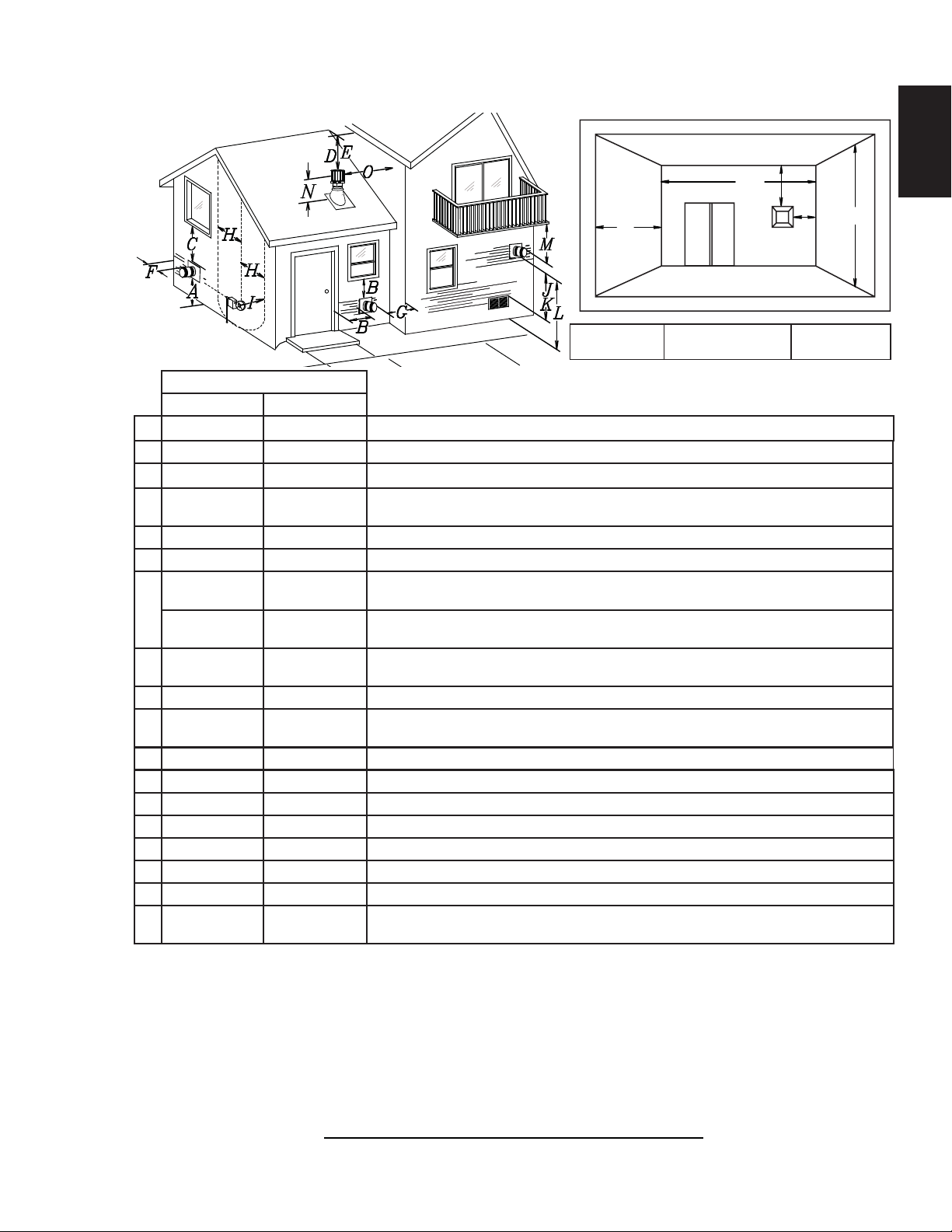
3.3 VENT TERMINAL CLEARANCES
11
EN
Q
M
R
Q
= 3 feet
MIN
(0.9m)
INSTALLATIONS
CANADA U.S.A.
A 12” (30.5cm) 12” (30.5cm) Clearance above grade, veranda porch, deck or balcony.
B 12” (30.5cm)
Δ
9” (228.6mm) ΔClearance to windows or doors that open.
C 12” (30.5cm)* 12” (30.5cm)* Clearance to permanently closed windows.
D 18” (45.7cm)** 18” (45.7cm)**
Vertical clearance to ventilated soffi ts located above the terminal within a horizontal distance
of 2’ (0.6m) from the centerline of the terminal.
E 12” (30.5cm)** 12” (30.5cm)** Clearance to unventilated soffi t.
F 0” (0mm) 0” (0mm) Clearance to an outside corner wall.
0” (0mm)*** 0” (0mm)***
G
2” (50.8mm)*** 2” (50.8mm)***
H 3’ (0.9m) 3’ (0.9m)****
Clearance to an inside non-combustible corner wall or protruding non-combustible obstructions
(chimney, etc.).
Clearance to an inside combustible corner wall or protruding combustible obstructions (vent
chase, etc.).
Clearance to each side of the centerline extended above the meter / regulator assembly to a
maximum vertical distance of 15’ (4.6m).
I 3’ (0.9m) 3’ (0.9m)**** Clearance to a service regulator vent outlet.
J 12” (30.5cm) 9” (228.6mm)
Clearance to a non-mechanical air supply inlet to the building or a combustion air inlet to any other
appliance.
K 6’ (1.8m) 3’ (0.9m) Clearance to a mechanical air supply inlet.
L 7’ (2.1m)‡ 7’ (2.1m)**** Clearance above a paved sidewalk or paved driveway located on public property.
M 12” (30.5cm)†† 12” (30.5cm)**** Clearance under a veranda, porch, deck or balcony.
N 16” (40.6cm) 16” (40.6cm) Clearance above the roof.
O 2’ (0.61m)†* 2’ (0.61m)†* Clearance from an adjacent wall including neighbouring buildings.
P 8’ (2.4m) 8’ (2.4m) Roof must be non-combustible without openings.
Q 3’ (0.9m) 3’ (0.9m) See chart for wider wall dimensions.
R 6’ (1.8m) 6’ (1.8m)
The terminal shall not be located less than 6 feet (1.8m) under a window that opens on a horizontal plane in a structure with three walls and a roof.
Δ
* Recommended to prevent condensation on windows and thermal breakage
** It is recommended to maximize the distance to vinyl clad soffi ts.
*** The periscope requires a minimum 18” (45,7cm) clearance from an inside corner.
**** This is a recommended distance. For additional requirements check local codes.
† 3 feet (0.91m) above if within 10 feet (3.1m) horizontally.
‡ A vent shall not terminate where it may cause hazardous frost or ice accumulations on adjacent property surfaces.
†† Permitted only if the veranda, porch, or deck is fully open on a minimum of two sides beneath the fl oor.
†* Recommended to prevent recirculation of exhaust products. For additional requirements check local codes.
See chart for deeper wall dimensions. The terminal shall not be installed on any wall that has
an opening between the terminal and the open side of the structure.
R
= 2 x
MAX
Q
ACTUAL
12.3C
G
R
MAX
P
IHHW
(4.6m)
W415-2201 / C / 07.04.19
12
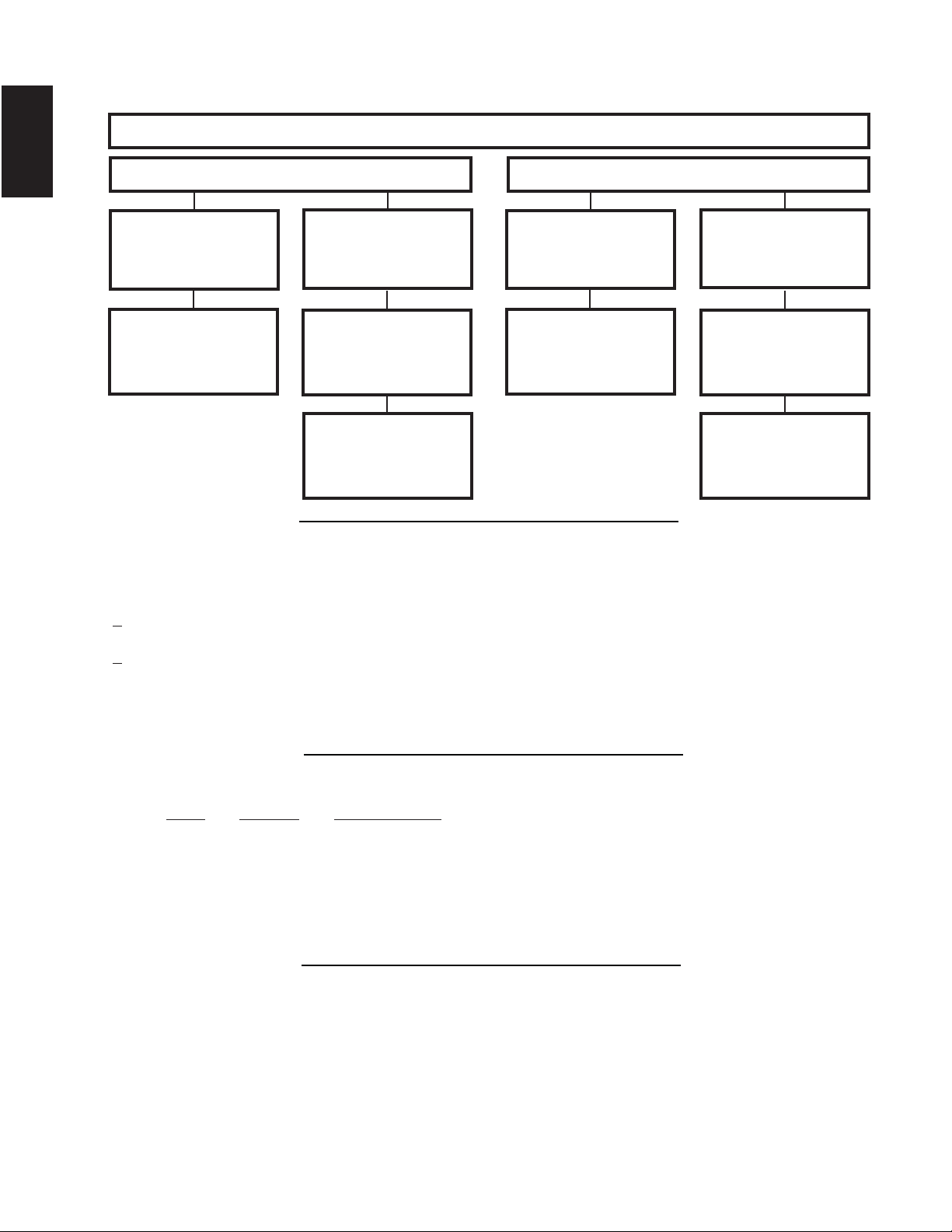
3.4 VENT APPLICATION FLOW CHART
EN
Vertical rise is equal
to or greater than
the horizontal run
Horizontal run +
vertical rise to
maximum of 40 feet
3.5 DEFINITIONS
For the following symbols used in the venting calculations and examples are:
> - greater than
> - equal to or greater than
< - less than
< - equal to or less than
HT - total of both horizontal vent lengths (Hr) and offsets (Ho) in feet
HR - combined horizontal vent lengths in feet
HO - offset factor: .03 (total degrees of offset - 90°*) in feet
VT - combined vertical vent lengths in feet
Horizontal Termination
Vertical rise is less
than horizontal run
Horizontal run +
vertical rise to
maximum of
(12m)
24.75 feet (7.5m)
4.2 times the
vertical rise equal to
or greater than the
horizontal run
TOP EXIT
Vertical rise is equal
maximum of 40 feet
Vertical Termination
to or greater than
the horizontal run
Horizontal run +
vertical rise to
(12m)
Vertical rise is less
than horizontal run
Horizontal run +
vertical rise to
maximum of 40 feet
(12m)
3 times the vertical
rise equal to or
greater than the
horizontal run
13.1A
14.1
3.6 ELBOW VENT LENGTH VALUES
FEET INCHES MILLIMETERS
1° 0.03 0.5 12.7
15° 0.45 6.0 152.4
30° 0.9 11.0 279.4
45° 1.35 16.0 406.4
90°* 2.7 32.0 812.8
* The fi rst 90° offset has a zero value and is shown in the formula as - 90°
W415-2201 / C / 07.04.19
15.1A
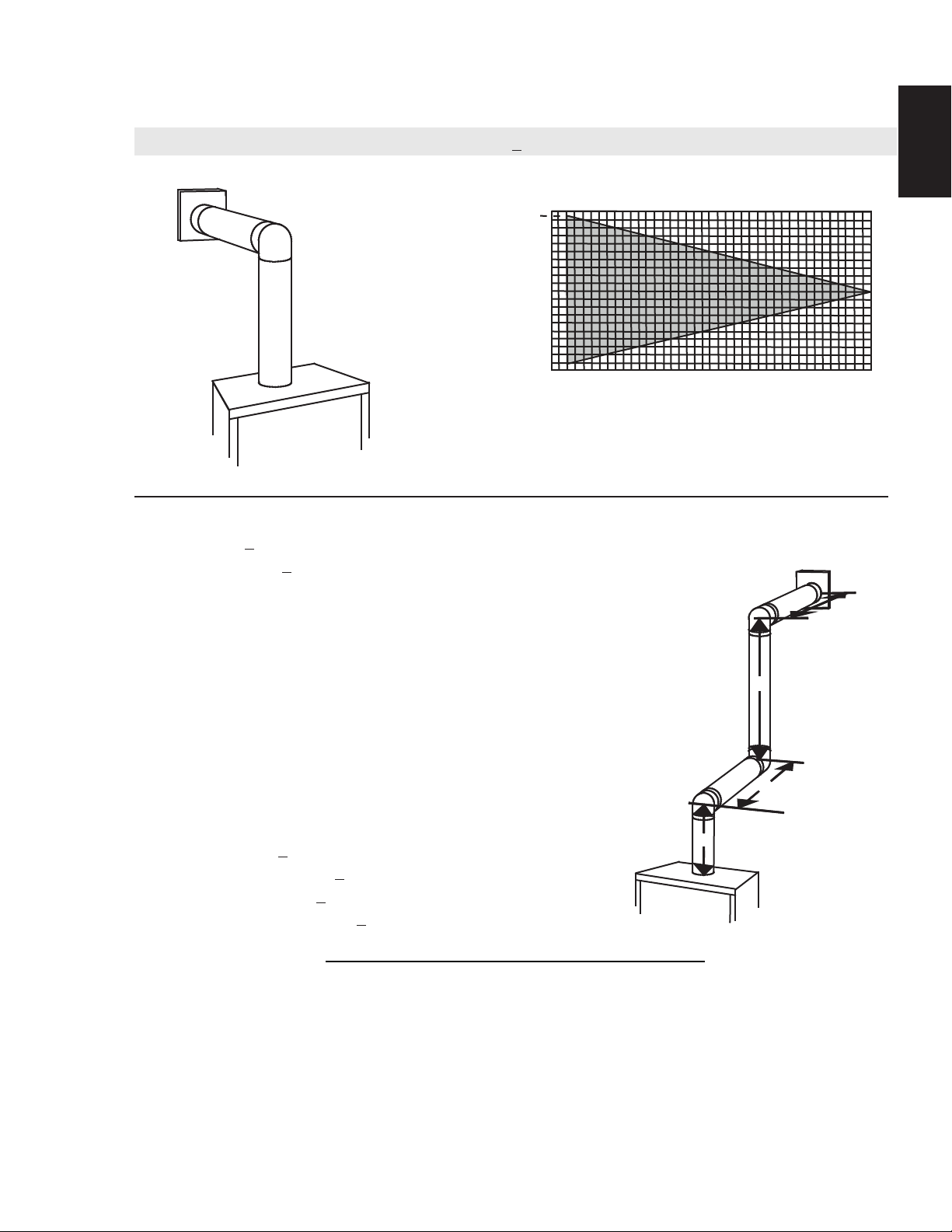
3.7 HORIZONTAL TERMINATION
13
(HT) < (VT)
Simple venting confi guration (only one 90° elbow)
REQUIRED
VERTICAL
RISE IN FEET
(METERS)VT
39 (11.9)
40 (12.2)
39 (11.9)
30 (9.1)
20 (6.1)
10 (3.1)
40 (12.2)
See graph to determine the required vertical
rise V
for the required horizontal run HT.
T
30 (9.1)
20 (6.1)
10 (3.1)
0
0
2.5
2.5
(0.8)5(1.5)
(0.8)5(1.5)
7.5
(2.3)
7.5
(2.3)
10
(3.1)
(3.1)
10
12.5
12.5
(3.8)15(4.6)
(3.8)15(4.6)
HORIZONTAL VENT RUN PLUS OFFSET IN
FEET (METERS) H
T
The shaded area within the lines represents
acceptable values for HT and V
For vent confi gurations requiring more than one 90° elbow, the following formulas apply:
Formula 1: HT < V
T
Formula 2: HT + VT < 40 feet (12.2m)
17.5
17.5
(5.3)20(6.1)
(5.3)20(6.1)
T
EN
Example:
V1 = 3 FT (0.9m)
V2 = 8 FT (2.4m)
VT = V1 + V2= 3 FT (0.9m ) + 8 FT (2.4m) = 11 FT (3.4m)
H1 = 2.5 FT (0.8m)
H2 = 2 FT (0.6m)
HR = H1 + H2 = 2.5 FT (0.8m) + 2 FT (0.6m) = 4.5 FT (1.4m)
HO = .03 (three 90° elbows - 90°) = .03 (270° - 90°) = 5.4 FT (1.7m)
HT = HR + HO = 4.5 FT (1.4m) + 5.4 FT (1.6m) = 9.9 FT (3m)
HT + VT = 9.9 FT (3m) + 11 FT (3.4m) = 20.9 FT (6.4m)
Formula 1: HT < V
T
9.9 FT (3m) < 11 FT (3.4m)
Formula 2: H
+ VT < 40 FT (12.2m)
T
20.9 FT (6.4m) < 40 FT (12.2m)
Since both formulas are met, this vent confi guration is acceptable.
90°
V
90°
1
16.1B
90°
H
2
V
2
H
1
W415-2201 / C / 07.04.19

EN
14
(HT) > (VT)
Simple venting configuration (only one 90° elbow)
REQUIRED
VERTICAL RISE
IN INCHES
(CENTIMETERS) V
See graph to determine the required vertical rise VT for the
required horizontal run H
150 (381)
147 (373)
100 (254)
T
57 (144)
50 (127)
24 (61)
.
T
5
0
(1.5)
3
(0.9)
HORIZONTAL VENT RUN PLUS OFFSET IN FEET (METERS) H
The shaded area within the lines represents acceptable
values for H
and VT
T
For vent configurations requiring more than one 90° elbow, the following formulas apply:
Formula 1: H
Formula 2: HT + V
< 4.2 V
T
T
< 24.75 feet (7.5 meters)
T
90°
H
1
Example 2:
V
= VT = 6 FT (1.8m)
1
H
= 3 FT (0.9m)
1
H
= 5 FT (1.5m)
2
H
= H
+ H
R
H
= .03 (two 90° elbows - 90°) = .03 (180° - 90°) = 2.7FT (0.8m)
O
H
= H
T
H
+ V
T
Formula 1: HT < 4.2 V
= 3 FT (0.9m) + 5 FT (1.5m) = 8 FT (2.4m)
1
2
+ H
= 8FT (2.4m) + 2.7FT (0.8m) = 10.7FT (3.3m)
R
O
= 10.7FT (3.3m) + 6FT (1.8m) = 16.7FT (5.1m)
T
4.2 VT = 4.2FT (1.3m) x 6FT (1.8m) = 25.2FT (7.7m)
T
V
1
10.7FT (3.3m) < 25.2FT (7.7m)
Formula 2: HT + V
16.7 FT (5.1m) <
< 24.75 FT (7.5m)
T
24.75 FT (7.5m)
90°
90°
H
1
Since both formulas are met, this vent configuration is acceptable.
Example 3:
= 4 FT (1.2m)
V
1
V
= 1.5 FT (0.5m)
2
V
= V
+ V
T
H
= 2 FT (0.6m)
1
H
= 1 FT (0.3m)
2
= 1 FT (0.3m)
H
3
H
= 1.5 FT (0.5m)
4
H
= H
R
H
= .03 (four 90° elbows - 90°) = .03 (360° - 90°) = 8.1 FT (2.5m)
O
H
= H
T
+ V
H
T
= 4FT (1.2m) + 1.5FT (0.5m) = 5.5FT (1.7m)
1
2
+ H2 + H
1
+ H
R
= 13.6 FT (4.2m) + 5.5 FT (1.7m) = 19.1 FT (5.8m)
T
+ H4 = 2FT (0.6m) + 1FT (0.3m) + 1FT (0.3m) + 1.5FT (0.5m) = 5.5 FTFT (1.7m)
3
= 5.5 FT (1.7m) + 8.1 FT (2.5m) = 13.6 FT (4.2m)
O
V
1
90°
10
(6.1)
90°
12.5
(3.8)
15
(4.6)
H
2
90°
H
19.5
(5.9)
20 (6.1)
V
3
T
H
2
H
4
2
Formula 1: HT < 4.2 V
4.2 VT = 4.2FT (1.3m) x 5.5FT (1.7m) = 23.1FT (7m)
13.6FT (4.2m) <
Formula 2: H
+ V
T
19.1FT (5.8m) < 24.75 (7.5m)
T
23.1FT (7m)
< 24.75 FT (7.5m)
T
Since both formulas are met, this vent configuration is acceptable.
W415-2201 / C / 07.04.19

3.8 VERTICAL TERMINATION
15
(HT) < (VT)
Simple venting configurations.
See graph to determine the required vertical rise V
required horizontal run HT.
40 (12.2)
30 (9.1)
REQUIRED
VERTICAL
RISE IN FEET
(METERS) V
T
3 (0.9)
20 (6.1)
10 (3.1)
0
5
(1.5)
HORIZONTAL VENT RUN PLUS OFFSET IN FEET (METERS) H
The shaded area within the lines represents acceptable
values for HT and V
For vent configurations requiring one or more 90° elbows the following formulas apply:
Formula 1: HT < V
Formula 2: HT + V
T
< 40 feet (12.2m)
T
10
(3.1)
EN
for the
T
15
(4.6)
T
20
(6.1)
T
Example:
V
= 5 FT (1.5m)
1
V
= 6 FT (1.8m)
2
V
= 10 FT (3.1m)
3
V
= V
+ V2 + V3 = 5FT (1.5m) + 6FT (1.8m) + 10FT (3.1m) = 21FT (6.4m)
T
1
H
= 8 FT (2.4m)
1
H
= 2.5 FT (0.8m)
2
H
= H
+ H
R
H
= .03 (four 90° elbows - 90°)
O
= .03 (360° - 90°) = 8.1 FT (2.5m)
H
= H
T
H
+ V
T
Formula 1: HT < V
Formula 2: HT + V
= 8FT (2.4m) + 2.5FT (0.8m) = 10.5 FT (3.2m)
1
2
+ H
= 10.5FT (3.2m) + 8.1FT (2.5m) = 18.6FT (5.7m)
R
O
= 18.6FT (5.7m) + 21FT (6.4m) = 39.6FT (12.1m)
T
T
18.6FT (5.7m) < 21FT (6.4m)
< 40 FT (12.19m)
T
39.6FT (12.1m) < 40FT (12.2m)
Since both formulas are met, this vent configuration is acceptable.
90°
V
3
90°
H
2
V
H
1
V
1
2
90°
90°
18.1A
W415-2201 / C / 07.04.19

16
EN
Simple venting configurations.
(HT) > (VT)
20 (6.1)
19 (5.8)
See graph to determine the required vertical rise V
required horizontal run H
.
T
for the
T
REQUIRED
VERTICAL
RISE IN FEET
(METERS) V
T
3 (0.9)
10 (3.1)
0
5
(1.5)
10
(3.1)
15
(4.6)
20
(6.1)
25
(7.6)
HORIZONTAL VENT RUN PLUS OFFSET IN FEET (METERS) H
The shaded area within the lines represents acceptable
values for H
and V
T
T
For vent configurations requiring more than two 90° elbows the following formulas apply:
Formula 1: H
Formula 2: HT + V
< 3V
T
T
< 40 feet (12.2m)
T
Example:
V
= 2 FT (0.6m)
1
V
= 1 FT (0.3m)
2
V
= 1.5 FT (0.5m)
3
V
= V1+V2+V3= 2FT (0.6m) + 1FT (0.3m) + 1.5FT (0.5m) = 4.5FT (1.4m)
T
H
= 6 FT (1.8m)
1
H
= 2 FT (0.6m)
2
H
= H
+ H
R
H
= .03 (four 90° elbows - 90°)
O
= .03 (360° - 90°) = 8.1 FT (2.5m)
H
= H
T
H
+ V
T
= 6FT (1.8m) + 2FT (0.6m) = 8 FT (2.4m)
1
2
+ H
= 8FT (2.4m) + 8.1FT (2.5m) = 16.1FT (4.9m)
R
O
= 16.1FT (4.9m) + 4.5FT (1.4m) = 20.6 FT (6.3m)
T
90°
H
V
1
1
90°
V
H
2
V
2
3
90°
Formula 1: HT < 3V
T
3VT = 3FT (0.9m) x 4.5FT (1.4m) = 13.5FT (4.1m)
16.1FT (4.9m) > 13.5FT (4.1m)
Since this formula is not met, this vent configuration is unacceptable.
Formula 2: HT + VT < 40 feet (12.2m)
20.6FT (6.3m) < 40 (12.2m)
Since only formula 2 is met, this vent configuration is unacceptable and a new appliance location or vent configuration
will need to be established to satisfy both formulas.
18.1_2B
30
(9.1)
T
90°
W415-2201 / C / 07.04.19
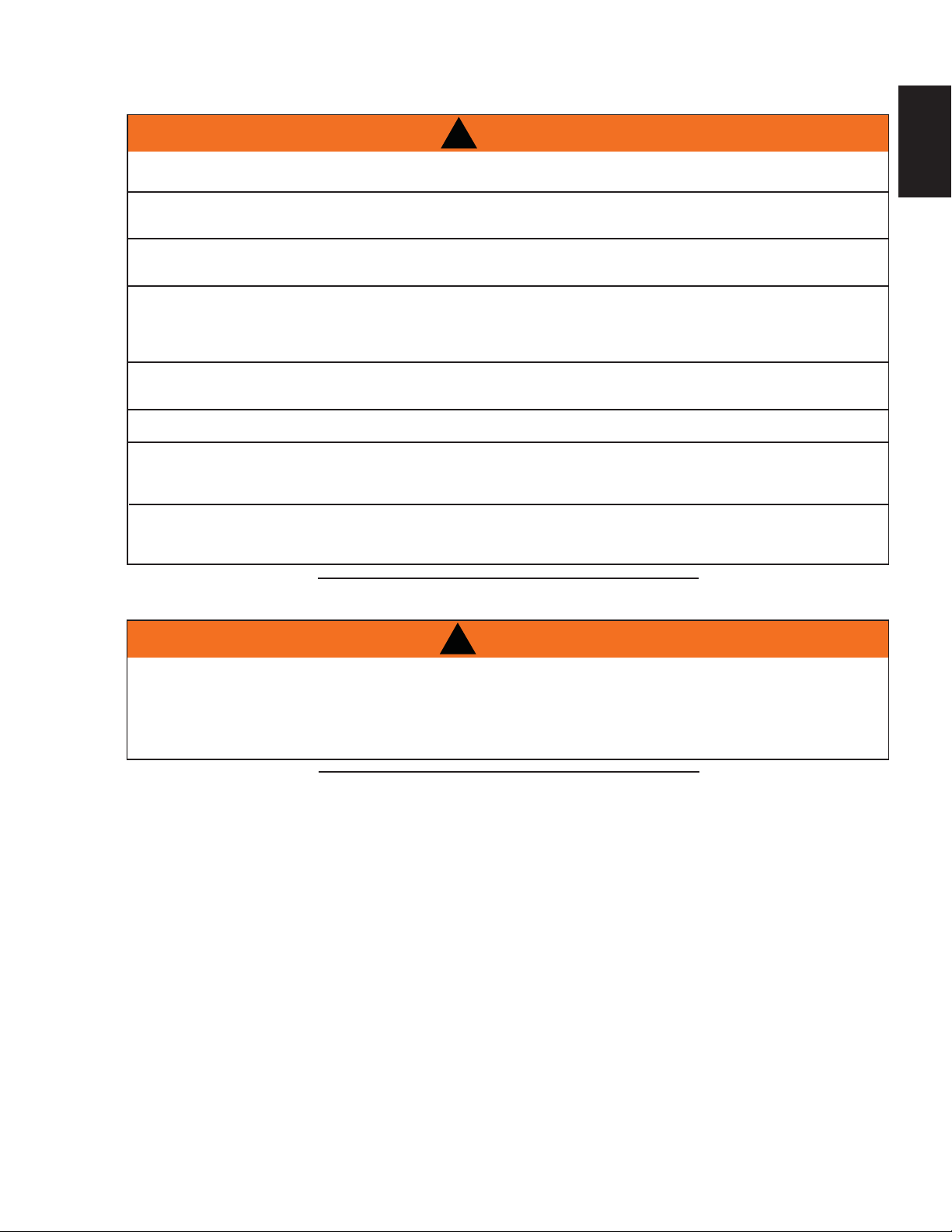
4.0 INSTALLATION
17
!
WARNING
ENSURE TO UNPACK ALL LOOSE MATERIALS FROM INSIDE THE FIREBOX PRIOR TO HOOKING UP
IF YOUR APPLIANCE IS SUPPLIED WITH A REMOTE, ENSURE THE REMOTE RECEIVER IS IN THE
“OFF” POSITION PRIOR TO HOOKING UP THE GAS AND ELECTRICAL SUPPLY TO THE APPLIANCE.
FOR SAFE AND PROPER OPERATION OF THE APPLIANCE, FOLLOW THE VENTING INSTRUCTIONS
ALL EXHAUST AND INTAKE VENT PIPE JOINTS MUST BE SEALED USING RED RTV HIGH TEMP
SILICONE SEALANT (W573-0002) (NOT SUPPLIED) OR BLACK HIGH TEMP MILL PAC (W573-0007)
(NOT SUPPLIED) WITH THE EXCEPTION OF THE APPLIANCE EXHAUST FLUE COLLAR WHICH MUST
IF USING PIPE CLAMPS TO CONNECT VENT COMPONENTS, A MINIMUM OF 3 SCREWS MUST ALSO
BE USED TO ENSURE THE CONNECTION CANNOT SLIP OFF.
RISK OF FIRE, EXPLOSION OR ASPHYXIATION. IMPROPER SUPPORT OF THE ENTIRE VENTING
SYSTEM MAY ALLOW VENT TO SAG AND SEPARATE. USE VENT RUN SUPPORTS AND CONNECT
VENT SECTIONS PER INSTALLATION INSTRUCTIONS.
RISK OF FIRE, DO NOT ALLOW LOOSE MATERIALS OR INSULATION TO TOUCH THE VENT PIPE.
REMOVE INSULATION TO ALLOW FOR THE INSTALLATION OF THE ATTIC SHIELD AND TO
THE GAS AND ELECTRICAL SUPPLY.
EXACTLY.
BE SEALED USING MILL PAC.
DO NOT CLAMP THE FLEXIBLE VENT PIPE.
MAINTAIN CLEARANCES TO COMBUSTIBLES.
68.2D
EN
4.1 WALL AND CEILING PROTECTION
DO NOT FILL THE SPACE BETWEEN THE VENT PIPE AND ENCLOSURE WITH ANY TYPE OF
MATERIAL. DO NOT PACK INSULATION OR COMBUSTIBLES BETWEEN CEILING FIRESTOPS.
ALWAYS MAINTAIN SPECIFIED CLEARANCES AROUND VENTING AND FIRESTOP SYSTEMS.
INSTALL WALL SHIELDS AND FIRESTOPS AS SPECIFIED. FAILURE TO KEEP INSULATION OR
OTHER MATERIALS AWAY FROM VENT PIPE MAY CAUSE FIRE.
For optimum performance it is recommended that all horizontal runs have a minimum of 1/4" (6.4mm) rise
per foot (0.9m) using fl exible venting. For safe and proper operation of the appliance, follow the venting
instructions exactly.
For clearance to combustible materials from the vent pipe, see “FRAMING” section.
!
WARNING
70.1
W415-2201 / C / 07.04.19
 Loading...