

Napoleon HD35NT, HD46PT, HD40NT, HD46NT, HD35PT Installation And Operating Instructions Manual
...Page 1

INSTALLER: LEAVE THIS MANUAL WITH THE APPLIANCE.
CONSUMER: RETAIN THIS MANUAL FOR FUTURE REFERENCE.
NEVER LEAVE CHILDREN OR OTHER AT RISK INDIVIDUALS ALONE WITH THE APPLIANCE.
INSTALLATION AND
EN
OPERATING INSTRUCTIONS
CONFORMS TO AMERICAN NATIONAL STANDARDS: ANSI Z21.50, CERTIFIED TO CANADIAN CSA 2.22 FOR VENTED GAS FIREPLACES.
CERTIFIED FOR CANADA AND UNITED STATES USING ANSI/CSA METHODS.
SAFETY INFORMATION
!
WARNING
If the information in these instructions
are not followed exactly, a fi re or
explosion may result causing property
damage, personal injury or loss of life.
- Do not store or use gasoline or other fl ammable
vapors and liquids in the vicinity of this or any
other appliance.
- WHAT TO DO IF YOU SMELL GAS:
• Do not try to light any appliance.
• Do not touch any electrical switch; do not use
any phone in your building.
• Immediately call your gas supplier from a
neighbour’s phone. Follow the gas supplier’s
instructions.
• If you cannot reach your gas supplier, call the
fi re department.
- Installation and service must be performed by a
qualifi ed installer, service agency or the supplier.
This appliance may be installed in an aftermarket,
permanently located, manufactured home (USA
only) or mobile home, where not prohibited by
local codes.
This appliance is only for use with the type of gas
indicated on the rating plate. This appliance is
not convertible for use with other gases, unless a
certifi ed kit is used.
Decorative Product: Not for use as a heating appliance.
HD35NT, HD40NT & HD46NT
NATURAL GAS
HD35PT, HD40PT & HD46PT
PROPANE
SAFETY BARRIER
HDF35KSB ILLUSTRATED
!
DANGER
HOT GLASS WILL CAUSE
BURNS.
DO NOT TOUCH GLASS UNTIL
COOLED.
NEVER ALLOW CHILDREN TO
TOUCH GLASS.
A barrier designed to reduce the risk of burns from
the hot viewing glass is provided with this appliance
and shall be installed for the protection of children
and other at-risk individuals.
FR
PG
69
Wolf Steel Ltd., 24 Napoleon Rd., Barrie, ON, L4M 0G8 Canada /
103 Miller Drive, Crittenden, Kentucky, USA, 41030
Phone (705)721-1212 • Fax (705)722-6031 • www.napoleonfi replaces.com • hearth@napoleonproducts.com
$10.00
BARRIER
CERTIFIED
1.36E
W415-1347 / A / 03.19.15
Page 2

EN
2
TABLE OF CONTENTS
1.0 INSTALLATION OVERVIEW 3
1.1 USING NON-COMBUSTIBLE MATERIAL 3
2.0 INTRODUCTION 4
2.1 DIMENSIONS 5
2.3 GENERAL INSTRUCTIONS 6
2.4 GENERAL INFORMATION 7
2.5 RATING PLATE INFORMATION 8
3.0 VENTING 9
3.1 VENTING LENGTHS AND COMPONENTS 9
3.2 TYPICAL VENT INSTALLATIONS 10
3.3 SPECIAL VENT INSTALLATIONS 11
3.3.1 PERISCOPE TERMINATION 11
3.3.2 CORNER TERMINATION 11
3.4 VENT TERMINAL CLEARANCES 12
3.5 VENT APPLICATION FLOW CHART 13
3.6 DEFINITIONS 13
3.7 ELBOW VENT LENGTHS 13
3.8 HORIZONTAL TERMINATION 14
3.9 VERTICAL TERMINATION 16
3.10 CO-AXIAL TO CO-LINEAR VENTING 18
4.0 INSTALLATION 19
4.1 WALL AND CEILING PROTECTION 19
4.1.1 HORIZONTAL INSTALLATION 20
4.1.2 VERTICAL INSTALLATION 20
4.2 USING FLEXIBLE VENT COMPONENTS 21
4.2.1 HORIZONTAL AIR TERMINAL INSTALLATION 21
4.2.2 VERTICAL AIR TERMINAL INSTALLATION 22
4.3 USING RIGID VENT COMPONENTS 23
4.3.1 HORIZONTAL AIR TERMINAL INSTALLATION 23
4.3.2 EXTENDED HORIZONTAL AIR TERMINAL INSTALLATION 23
4.3.3 VERTICAL VENTING INSTALLATION 24
4.4 MOBILE HOME 25
4.5 ACCESS PANEL FOR GAS LINE CONNECTION 25
4.6 GAS INSTALLATION 26
5.0 FRAMING 27
5.1 MINIMUM CLEARANCE TO COMBUSTIBLES 29
5.2 MINIMUM CLEARANCE TO COMBUSTIBLE ENCLOSURES 30
5.3 INSTALLING NON-COMBUSTIBLE BOARD 31
5.4 ALCOVE INSTALLATION 32
5.5 MINIMUM MANTEL CLEARANCES 33
5.6 NON-COMBUSTIBLE FACING MATERIAL 33
6.0 FINISHING 34
6.1 SAFETY SCREEN REMOVAL / INSTALLATION 34
6.3 FRONT SURROUND INSTALLATION 35
6.2 GLASS DOOR REMOVAL / INSTALLATION 35
6.4 LOG PLACEMENT 36
6.5 GLOWING EMBER PLACEMENT 38
6.6 CHARCOAL EMBERS 38
6.7 OPTIONAL VERMICULITE 38
6.10 LAVA ROCK 38
6.8 OPTIONAL CHARCOAL LUMPS (STANDARD ON HD46) 38
6.9 LOGO PLACEMENT 38
7.0 OPTIONAL BLOWER INSTALLATION 39
7.1 ACCESSING THE BLOWER 39
7.2 INSTALLING THE BLOWER 40
8.0 WIRING DIAGRAM / ELECTRICAL INFORMATION 41
8.1 WIRING REQUIREMENTS 41
8.2 OPTIONAL ACCESSORIES REQUIREMENTS 41
8.3 JUNCTION BOX INSTALLATION 42
8.4 WIRING DIAGRAM 43
9.0 OPERATION 44
10.0 ADJUSTMENT 45
10.1 PRESSURE ADJUSTMENT 45
10.2 VENTURI ADJUSTMENT 45
10.3 FLAME CHARACTERISTICS 46
11.0 MAINTENANCE 46
11.1 ANNUAL MAINTENANCE 47
11.2 DOOR GLASS REPLACEMENT 48
11.3 CARE OF GLASS 48
11.4 CARE OF PLATED PARTS 48
12.0 REPLACEMENT PARTS 49
13.0 HD35 OVERVIEW 50
14.0 HD35 VALVE TRAIN ASSEMBLY 51
15.0 HD35 ACCESSORIES 52
16.0 HD35 ACCESSORIES (PAGE 2) 53
17.0 HD40 OVERVIEW 54
18.0 HD40 VALVE TRAIN ASSEMBLY 55
NOTE: Changes, other than editorial, are denoted by a vertical line in the margin.
W415-1347 / A / 03.19.15-
Page 3
19.0 HD40 ACCESSORIES 56
20.0 HD40 ACCESSORIES (PAGE 2) 57
21.0 HD46 OVERVIEW 58
22.0 HD46 VALVE TRAIN ASSEMBLY 59
23.0 HD46 ACCESSORIES 60
24.0 HD46 ACCESSORIES (PAGE 2) 61
25.0 TROUBLESHOOTING 62
26.0 WARRANTY 64
27.0 SERVICE HISTORY 65
28.0 NOTES 66
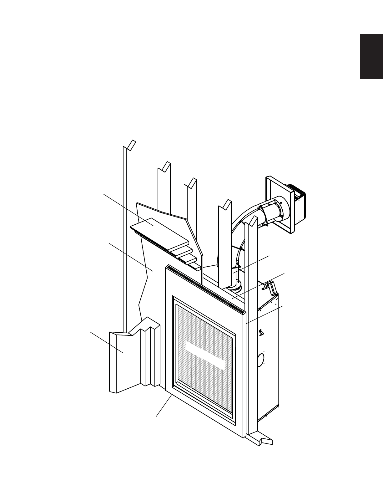
1.0 INSTALLATION OVERVIEW
1.1 USING NON-COMBUSTIBLE MATERIAL
Mantel, see “MINIMUM
MANTEL CLEARANCES” section.
3
EN
Enclosures, see the
section “MINIMUM
CLEARANCES TO
COMBUSTIBLE
ENCLOSURES”
section for drywall (or
other combustible
material).
Framing, see
“FRAMING”
section.
Side
Wall
SAFETY BARRIER
Venting, see “VENTING”
section.
Framing, see “FRAMING”
section.
Enclosures, see the
section “MINIMUM
CLEARANCE TO COMBUSTIBLE ENCLOSURES” section for
non-combustible materials
such as tile, marble,
granite, etc.
Rating plate, see “RATING
PLATE INFORMATION”
section.
W415-1347 / A / 03.19.15
Page 4

4
2.0 INTRODUCTION
EN
• THIS APPLIANCE IS HOT WHEN OPERATED AND CAN CAUSE SEVERE BURNS IF CONTACTED.
• ANY CHANGES OR ALTERATIONS TO THIS APPLIANCE OR ITS CONTROLS CAN BE DANGEROUS AND IS
PROHIBITED.
• Do not operate appliance before reading and understanding operating instructions. Failure to operate appliance
according to operating instructions could cause fi re or injury.
• Risk of fi re or asphyxiation do not operate appliance with fi xed glass removed.
• Do not connect 110 volts to the control valve.
• Risk of burns. The appliance should be turned off and cooled before servicing.
• Do not install damaged, incomplete or substitute components.
• Risk of cuts and abrasions. Wear protective gloves and safety glasses during installation. Sheet metal edges may
be sharp.
• Do not burn wood or other materials in this appliance.
• Children and adults should be alerted to the hazards of high surface temperature and should stay away to
avoid burns or clothing ignition.
• Young children should be carefully supervised when they are in the same room as the appliance.
Toddlers, young children and others may be susceptible to accidental contact burns. A physical barrier
is recommended if there are at risk individuals in the house. To restrict access to an appliance, install an
adjustable safety gate to keep toddlers, young children and other at risk individuals out of the room and
away from hot surfaces.
• Clothing or other fl ammable material should not be placed on or near the appliance.
• Due to high temperatures, the appliance should be located out of traffi c and away from furniture and
draperies.
• Ensure you have incorporated adequate safety measure to protect infants/toddlers from touching hot surfaces.
• Even after the appliance is out, the glass and/or screen will remain hot for an extended period of time.
• Check with your local hearth specialty dealer for safety screens and hearth guards to protect children from hot
surfaces. These screens and guards must be fastened to the fl oor.
• Any safety screen, guard or barrier removed for servicing the appliance, must be replaced prior to operating
the appliance.
• The appliance is a vented gas-fi red appliance. Do not burn wood or other materials in the appliance
• It is imperative that the control compartments, burners and circulating blower and its passageway in the appliance
and venting system are kept clean. The appliance and its venting system should be inspected before use and at
least annually by a qualifi ed service person. More frequent cleaning may be required due to excessive lint from
carpeting, bedding material, etc. The appliance area must be kept clear and free from combustible materials,
gasoline and other fl ammable vapors and liquids.
• Under no circumstances should this appliance be modifi ed.
• This appliance must not be connected to a chimney fl ue pipe serving a separate solid fuel burning appliance.
• Do not use this appliance if any part has been under water. Immediately call a qualifi ed service technician to inspect
the appliance and to replace any part of the control system and any gas control which has been under water.
• Do not operate the appliance with the glass door removed, cracked or broken. Replacement of the glass should be
done by a licensed or qualifi ed service person.
• Do not strike or slam shut the appliance glass door.
• When equipped with pressure relief doors, they must be kept closed while the appliance is operating to prevent
exhaust fumes containing carbon monoxide, from entering into the home. Temperatures of the exhaust escaping
through these openings can also cause the surrounding combustible materials to overheat and catch fi re.
• Only doors / optional fronts certifi ed with the appliance are to be installed on the appliance.
• Keep the packaging material out of reach of children and dispose of the material in a safe manner. As with all plastic
bags, these are not toys and should be kept away from children and infants.
• As with any combustion appliance, we recommend having your appliance regularly inspected and serviced as well
as having a Carbon Monoxide Detector installed in the same area to defend you and your family against Carbon
Monoxide.
• Ensure clearances to combustibles are maintained when building a mantel or shelves above the appliance.
Elevated temperatures on the wall or in the air above the appliance can cause melting, discolouration or damage of
decorations, a T.V. or other electronic components.
• A barrier designed to reduce the risk of burns from the hot viewing glass is provided with this appliance and
shall be installed.
• If the barrier becomes damaged, the barrier shall be replaced with the manufacturer’s barrier for this
appliance.
• Installation and repair should be done by a qualifi ed service person. The appliance should be inspected
before use and at least annually by a professional service person. More frequent cleaning may be required
due to excessive lint from carpeting, bedding material, etc. It is imperative that control compartments,
burners and circulating air passageways of the appliance be kept clean.
W415-1347 / A / 03.19.15-
!
WARNING
3.2C
Page 5
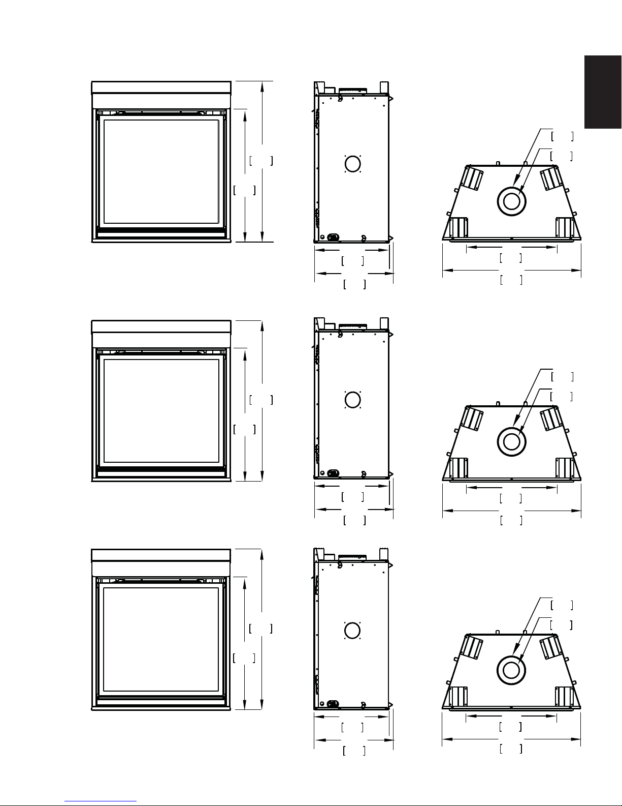
2.1 DIMENSIONS
1041mm
33 3/4"
857mm
41"
Ø
7 "
178mm
Ø
4 "
102mm
5
EN
HD35 ILLUSTRATED
HD40 ILLUSTRATED
1041mm
33 3/4"
857mm
41"
20”
508mm
20 1/2”
521mm
20”
508mm
20 1/2”
521mm
23”
584mm
35 1/4”
895mm
28”
711mm
40 1/4”
1022mm
Ø
7 "
178mm
Ø
4 "
102mm
HD46 ILLUSTRATED
1041mm
33 3/4"
857mm
41"
20”
508mm
20 1/2”
521mm
Ø
7 "
178mm
Ø
4 "
102mm
34”
864mm
46 1/4”
1175mm
W415-1347 / A / 03.19.15
Page 6
6
A
A
2.3 GENERAL INSTRUCTIONS
EN
ALWAYS LIGHT THE PILOT WHETHER FOR THE FIRST TIME OR IF THE GAS SUPPLY HAS RUN OUT,
PROVIDE ADEQUATE CLEARANCE FOR SERVICING AND OPERATING THE APPLIANCE.
NEVER OBSTRUCT THE FRONT OPENING OF THE APPLIANCE.
OBJECTS PLACED IN FRONT OF THE APPLIANCE MUST BE KEPT A MINIMUM OF 48” (1219mm) FROM
SURFACES AROUND AND ESPECIALLY ABOVE THE APPLIANCE CAN BECOME HOT. AVOID CONTACT
HIGH PRESSURE WILL DAMAGE VALVE. DISCONNECT GAS SUPPLY PIPING BEFORE PRESSURE TESTING GAS
LINE AT TEST PRESSURES ABOVE 1/2 PSIG. CLOSE THE MANUAL SHUT-OFF VALVE BEFORE PRESSURE
TESTING GAS LINE AT TEST PRESSURES EQUAL TO OR LESS THAN 1/2 PSIG (35 mb).
USE ONLY WOLF STEEL APPROVED OPTIONAL ACCESSORIES AND REPLACEMENT PARTS WITH THIS APPLIANCE.
USING NON-LISTED ACCESSORIES (BLOWERS, DOORS, LOUVRES, TRIMS, GAS COMPONENTS, VENTING
COMPONENTS, ETC.) COULD RESULT IN A SAFETY HAZARD AND WILL VOID THE WARRANTY AND CERTIFICATION.
THIS GAS APPLIANCE SHOULD BE INSTALLED AND SERVICED BY A QUALIFIED INSTALLER to
conform with local codes. Installation practices vary from region to region and it is important to know the
specifi cs that apply to your area, for example in Massachusetts State:
• This product must be installed by a licensed plumber or gas fi tter when installed within the commonwealth
of Massachusetts.
• The appliance damper must be removed or welded in the open position prior to installation of an appliance
insert or gas log.
• The appliance off valve must be a “T” handle gas cock.
• The fl exible connector must not be longer than 36 inches (914mm).
• A Carbon Monoxide detector is required in all rooms containing gas fi red appliances.
• The appliance is not approved for installation in a bedroom or bathroom unless the unit is a direct vent
sealed combustion product.
!
WARNING
WITH THE GLASS DOOR OPENED OR REMOVED.
PROVIDE ADEQUA TE VENTILA TION.
THE FRONT FACE OF THE APPLIANCE.
WHEN THE APPLIANCE IS OPERATING.
FIRE RISK. EXPLOSION HAZARD.
The installation must conform with local codes or, in
absence of local codes, the National Gas and Propane
Installation Code CSA B149.1 in Canada, or the National
Fuel Gas Code, ANSI Z223.1 / NFPA 54 in the United
States. Suitable for mobile home installation if installed in
accordance with the current standard CAN/CSA Z240MH
Series, for gas equipped mobile homes, in Canada or
NSI Z223.1 and NFPA 54 in the United States.
s long as the required clearance to combustibles is
maintained, the most desirable and benefi cial location
for an appliance is in the center of a building, thereby
allowing the most effi cient use of the heat created. The location of windows, doors and the traffi c fl ow in the
room where the appliance is to be located should be considered. If possible, you should choose a location
where the vent will pass through the house without cutting a fl oor or roof joist.
If the appliance is installed directly on carpeting, vinyl tile or other combustible material other than wood
fl ooring, the appliance shall be installed on a metal or wood panel extending the full width and depth.
Some appliances have optional fans or blowers. If an optional fan or blower is installed, the junction box must
be electrically connected and grounded in accordance with local codes, use the current CSA C22.1 Canadian
Electrical Code in Canada or the ANSI/NFPA 70 National Electrical code in the United States.
www.ncertied.org
We suggest that our gas
hearth products be installed
and serviced by professionals
who are certied in the U.S.
by the National Fireplace
®
Institute
(NFI) as NFI Gas
Specialists
4.1B
W415-1347 / A / 03.19.15-
Page 7

2.4 GENERAL INFORMATION
FOR YOUR SATISFACTION, THIS APPLIANCE HAS BEEN TEST-FIRED TO ASSURE ITS OPERATION
AND QUALITY!
This appliance is approved for bathroom, bedroom and bed-sitting room installations and is suitable for mobile
home installations.
These appliances are equipped with tempered glass. Replacement glass must be obtained from your authorized dealer / distributor and is identifi ed in the replacement parts list. Do not substitute materials.
This appliance is not convertible for use with other gases, unless a certifi ed kit is used.
Expansion / contraction noises during heating up and cooling down cycles are normal and are to be expected.
Changes in fl ame appearance from “HI” to “LO” is more evident in natural gas than in propane.
Use only accessories designed for and listed with your specifi c appliance.
High Elevations
Input ratings are shown in Btu per hour and are certifi ed without de-rating up to 4,500 feet (1372m) above sea
level. For Installations at the elevations above 4,500 feet (1372m) and in the absence of specifi c recommenda-
tions from the local authority having jurisdiction, the high altitude input rating shall be reduced at the rate of 4%
for each additional 1,000 feet (305m).
7
EN
GAS SPECIFICATIONS
Model Fuel Gas
Control
Max.
Input
BTU/h
Min.
Input
BTU/h
Air shutter set-
ting
HD35NT Nat IPI Hi/Lo 25,000 17,500 1/8” (3mm) Open
HD35PT Prop* IPI Hi/Lo 25,000 17,500 5/16” (8mm) Open
HD40NT Nat IPI Hi/Lo 27,000 18,900 1/8” (3mm) Open
HD40PT Prop* IPI Hi/Lo 27,000 18,900 3/8” (10mm) Open
HD46NT Nat IPI Hi/Lo 30,000 21,000 1/8” (3mm) Open
HD46PT Prop* IPI Hi/Lo 30,000 21,000 3/8” (10mm) Open
IPI - Intermittent Pilot Ignition System
* Using conversion kit
** Maximum Values
Conversions must be made by a qualifi ed service
technician using Wolf Steel specifi ed and approved parts.
GAS INLET AND MANIFOLD
PRESSURES
Natural Propane
Minimum Inlet 4.5” (11mb) w.c. 11” (27mb) w.c.
Maximum Inlet 7” (17mb) w.c. 13” (32mb) w.c.
Manifold Pressure 3.5” (9mb) w.c. 10” (25mb) w.c.
EFFICIENCY RATINGS
Model Steady State(%) AFUE%**
HD35NT 82.1% 77.2%
HD35PT 82.1% 77.2%
HD40NT 80.5% 76.3%
HD40PT 80.5% 76.3%
HD46NT 82.9% 79.2%
HD46PT 82.9% 79.2%
The optional heat circulating blower is supplied with a cord.
The junction box must be electrically connected and grounded in accordance with local codes. In the absence
of local codes, use the current CSA C22.1 Canadian Electrical Code in Canada or the ANSI/NFPA 70 National
Electrical Code in the United States.
This appliance is equipped with a power back up control system. Two 1.5 volt “D” batteries (not supplied) are
required for the battery pack included in the system. Use Alkaline batteries only.
W415-1347 / A / 03.19.15
Page 8
EN
OLUMNN
P4:P4:
%65.1%
H TH
SIS
UNUN
OIT O
NNLLYY
WITHWITH
SSURE:MANIFOLD PR E
10" WA
PRESSION AU COLLECTEUPRESSION AU
MINIMUM SUPPLY PRESINIMUM SUPPL
PRESSION D'ALIMENSSION D'ALIME
MAXIMUM SUPPLYMAXIMUM SUPPLY
PRESSION D'ALPRESSION D'A
P4:P4:
%65.1%
TIONTION
ATIONATION
T
ATION REDUITEATION REDUITE
0-4500FT (0-1370m)0-4500FT (0-1370m)
h30,000 BTU/h
21,000 BTU/h
D46PT
PropanePropan
PP
OO
URUR
I
NSNS
TTALLAA
TIOTTAALLLLAATT
OIONNDANSS
UNEUNE
M
/
CSCS
AA
ZZ
240M240M
H
SÉRR
IEEDEDE M M
AA
S
O
LAANNOORRMMEE
DED
SÉCURÉCUR
II
TÉTÉEETTD
C
OO
L
EE
CASCAS O OÙÙC
ECETTENNOO
RR
MMEE
DES
ÉÉ
TATA
TS-UTS-U
I
TÈRE
DEDE
MM
SESURES
DEDE
SÉCURSÉ
TÉ
CC
OO
NTRE
NTRE
S
SS
I
TESTES
EETT L L
ESESCCOMM
UNAUTÉSUNAUTÉS,,GD-565
K
T
, L
FOYERYER
ESES
T T
CC
OO
NFOORRMMEEÀÀ L L
AA
EULMENT AVEC BARRIÈRE W565-0175. SUIVEZIÈRE W565-0175. SUIVE
,
CE FOCE F
NVEN
T T
TOP/ DESSUS DE L’ÉVENT TOP/ DESSUS DE L’ÉVENT
0 0
VENT BOTTOM / DESSOUS DE L’ÉVENVENT BOTTOM / DESSOUS DE L’É
U 13"*
13"*
IZONTAL EXTENSION / EXTENSION HORIZO
ON MA
MANNUALUAL FFOROR
GG
RREAEATTER ER
EXEND
'II
ANSTA
LL
LALA
TIOTIO
8
63.3%
HD35
64.3%
HD40
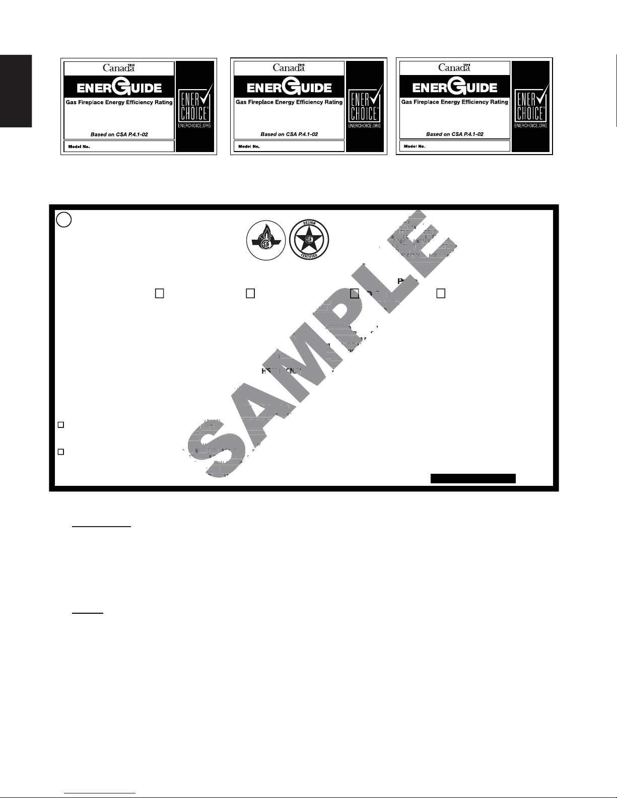
2.5 RATING PLATE INFORMATION
DIRECT VENT GAS FIREPLACE . SUITABLE FOR BEDROOM, BATHROOM AND BED-SITTING
ROOM INSTALLATION. SUITABLE FOR MOBILE HOME INSTALLATION IF INSTALLED IN
ACCORDANCE WITH THE CURRENT STANDARD CAN/CSA Z240MH SERIES GAS EQUIPPED MOBILE
HOMES, IN CANADA OR IN THE UNITED STATES THE MANUFACTURED HOME CONTRUCTION
AND SAFETY STANDARD, TITLE 24 CFR, PART 3280. WHEN THIS US STANDARD IS NOT APPLICABLE
USE THE STANDARD FOR FIRE SAFETY CRITERIA FOR MANUFACTURED HOME INSTALLATIONS, SITES
AND COMMUNITIES, ANSI / NFPA 501A. WHEN INSTALLED WITH SCREEN KIT GD-565KT, THE FIREPLACE
COMPLIES WITH CGA CERTIFICATION REQUIREMENT CR95-006. FOR USE ONLY WITH BARRIER
W565-0175. FOLLOW THE INSTALLATION INSTRUCTIONS LOCATED IN THE INSTALLATION MANUAL.
THIS VENTE D G A S F IR EP LA C E I S N OT FO R US E WITH AIR FILTERS AND NOT
FOR USE WITH SOLID FUEL. FOR USE WITH GLASS DOORS CERTIFIED WITH THIS UNIT ONLY
WARNING: DO NOT ADD ANY MATERIAL TO THE APPLIANCE, WHICH WILL COME IN
CONTACT WITH THE FLAMES, OTHER THAN THAT SUPPLIED BY THE MANUFACTURER WITH
THE APPLIANCE.
DECORATIVE PRODUCT: NOT FOR USE AS A HEATING APPLIANCE
MINIMUM CLEARANCE TO COMBUSTIBLE MATERIALS / DEGAGEMENTS MINIMAUX DES MATERIAUX COMBUSTIBLES:
WOLF STEEL LTD.
24 Napoleon Rd. Barrie,
Ontario L4M 0G8 Canada
WOLF STEEL USA
103 Miller Drive,
Crittenden, Kentucky, USA, 41030
CONFORMS TO / CONFORME AUX: ANSI Z21.50-2014, CERTIFIED TO / CERTIFIE CSA 2.22-2014 VENTED GAS FIREPLACE / FOYER À GAZ VENTILÉ.ES:
CERTIFIED
CERTIFIED FOR
CERTIFIEE POUR
REFERENCE # 161746
REDUCED INPUT/ALIMENTATION REDUITE
P4: 65.1%
HD46NT
Natural Gas/Gaz Naturel Propane
CHD46NT
0-4500 FT (0-1370m)
30,000 BTU/h
21,000 BTU/h
MANIFOLD PRESSURE: 3.5” WATER COLUMN
PRESSIONAU COLLECTEUR: 3.5" D'UNE COLONNE D'EAU
PRESSION D'ALIMENTATION MINIMALE: 4.5" D'UNE COLONNE D'EAU
MINIMUM SUPPLY PRESSURE: 4.5" WATER COLUMN
MAXIMUM SUPPLY PRESSURE: 7.0" WATER COLUMN
PRESSION D'ATATION MAXIMALE: 7.0" D'UNE COLONNE D'EAU
I
TOP/DESSUS 0 RECESSED DEPTH / PROFONDEUR D'ENCASTRE 20½"
FLOOR / PLANCHER 0 VENT SIDES / COTES DE L'EVENT 1"
SIDES / COTES 0
ARRIERE 0 VENT BOTTOM / DESSOUS DE L’ÉVENT 1"
BACK/
MANTLE / MANTEAU 13"*
MAXIMUM HORIZONTAL EXTENSION / EXTENSION HORIZONTALE MAXIMALE: 2".
*
SEE INSTRUCTION MANUAL FOR GREATER EXTENSIONS SE RÉFÉRER AU
MANUEL
D'INSTRUCTION POUR DES EXTENSIONS PLUS GRANDES.
SEE OWNER'S INSTRUCTION MANUAL FOR MINIMUM AND MAXIMUM VENT LENGTHS.
SE RÉFÉRER AU MANUEL D'INSTALLATION DU PRO PRIÉTAIRE POUR LES LONGUEURS
D'EVACUATION MINIMALE EV MAXIMALE.
VENT TOP/ DESSUS DE L’ÉVENT 2"
VE
EXT
NST
CANADA USA
MODEL
ALTITUDE / ELEVATION
INPUT/ALIMENTATION
65.1
IT
65.1%
HD46
FOYER À GAZ VENTILÉ. HOMOLOGUÉ POUR INSTALLATION DANS UNE CHAMBRE À COUCHER, UNE SALLE DE BAIN ET
UN STUDIO. APPROPRIÉ POUR INSTALLATION DANS UNE MAISON MOBILE SI SON INSTALLATION EST CONFORME AUX
EXIGENCES DE LA NORME CAN/CSA Z240MH SÉRIE DE MAISONS MOBILES ÉQUIPÉES AU GAZ, EN VIGUEUR AU CANADA,
OU AUX ÉTATS-UNIS, SELON LA NORME DE SÉCURITÉ ET DE CONSTRUCTION DE MAISONS MANUFACTURÉES, TITRE 24
CFR, SECTION 3280. DANS LE CAS OÙ CETTE NORME DES ÉTATS-UNIS NE PEUT ÊTRE APPLIQUÉE, SE RÉFÉRER À LA
NORME RELATIVE AU CRITÈRE DE MESURES DE SÉCURITÉ CONTRE L'INCENDIE POUR LES INSTALLATIONS DANS LES
MAISONS MANUFACTURÉES, LES SITES ET LES COMMUNAUTÉS, ANSI/NFPA 501A. LORSQU'IL EST INSTALLÉ AVEC LE
INCELLES GD-565KT, LE FOYER EST CONFORME À LA NORME DE CERTIFICATION DE L'ACG CR95-006.
PARE-ÉT
UNE UTILISER SEULMENT AVEC BARRIÈRE W565-0175. SUIVEZ LES INSTRUCTIONS D'INSTALLATION SE TROUVENT
DANS LE MANUEL D'INSTALLATION.
HD46PT
HD46PT
0-4500FT (0-1370m)
30,000 BTU/h
30,000 BTU/
MANIFOLD PR ESSURE: 10" WATER COLUMN
MANIFOLD PR E
PRESSION AU COLLECTEUR: 10" D'UNE COLONNE D'EAU
MINIMUM SUPPLY PRESSURE: 11" WATER COLUMN
PRESSION D'ALIMENTATION MINIMALE: 11" D'UNE COLONNE D'EAU
MAXIMUM SUPPLY PRESSURE: 13" WATER COLUMN
PRESSION D'ALIMENTATION MAXIMALE: 13" D'UNE COLONNE D'EAU
P4: 65.1%
CE FOYER À GAZ VENTILÉS NE DOIT PAS ÊTRE UTILISÉ AVEC
ET NE DOIT PAS ÊTRE UTILISÉ AVEC UN COMBUSTIBLE SOLIDE. UTILISER A VEC
LES PORTES
21,000 BTU/h
65.1
VITRÉES HOMOLOGUÉES AVEC CETTE UNITÉ SEULEMENT.
AVERTISSEMENT: N’A JOUTEZ PAS A CET APPAREIL AUCUN MATERIAU DEVANT ENTRER EN CONTACT AVEC
LES FLAMMES AUTRE QUE CELUI QUI EST FOURNI AVEC CET APPAREIL PAR LE FABRICANT.
PRODUIT DÉCORATIF: NE PAS UTILISER COMME APPAREIL DE CHAUFFAUGE
THE APPLIANCE MIST BE VENTED USING THE APPROPROATE WOLF STEEL VENT KITS. SEE OWNERS
INSTALLATION MANUAL FOR VENTING SPECIFICS. PROPER REINSTALLATION AND RESEALING IS NECESSARY
AFTER SERVICING THE VENT-AIR INTAKE SYSTEM. L’APPAREIL DOIT ÉVACUER SES GAZ EN UTILISANT
L’ENSEMBLE D’EVACUATION PROPRE À WOLF STEEL. SE RÉFÉRER AU MANUEL D’INSTALLATION DU
PROPRIÉTAIRE POUR LES SPÉCIFICATIONS DE L’ÉVACUATION. IL EST IMPORTANT DE BIEN RÉINSTALLER ER
RESCELLER L’ÉVENT APRÉS AVOIR EFFECTUÉ LE SERVICE DU SYSTÊM DE PRISE D’AIR
ELECTRICAL RATING / CLASSIFICATION: 115V, 60HZ, LESS THAN 12 AMPS.
SPÉCIFICATIONS ÉLECTRIQUES : 115 V, 60 HZ, MOINS DE 12 A.
OPTIONAL FAN KIT / SOUFFLERIE OPTIONNELLE : GZ550-KT, GD65
SERIAL NUMBER/NO. DE SERIE:
I
I
H
I
I
ETT
ESURE
, LE
I
E
E
ITÉ
NF
POUR
CHD46PT
DES FILTRES À AIR
HD46
W385-1995
INSTALLER: It is your responsibility to check off the appropriate box on the rating plate according to
the model, venting and gas type of the appliance.
For rating plate location, see “INSTALLATION OVERVIEW” section.
This illustration is for reference only. Refer to the rating plate on the appliance for accurate information.
NOTE: The rating plate must remain with the appliance at all times. It must not be removed.
A barrier designed to reduce the risk of burns from the hot viewing glass is provided with the
appliance and must be installed.
W415-1347 / A / 03.19.15-
Page 9
3.0 VENTING
9
!
WARNING
RISK OF FIRE, MAINTAIN SPECIFIED AIR SPACE CLEARANCES TO VENT PIPE AND APPLIANCE.
IF VENTING IS INCLUDED WITH SPACERS THE VENT SYSTEM MUST BE SUPPORTED EVERY 3FT
(0.9m) FOR BOTH VERTICAL AND HORIZONTAL RUNS. USE SUPPORTS OR EQUIVALENT
NON-COMBUSTIBLE STRAPPING TO MAINTAIN THE REQUIRED CLEARANCE FROM
COMBUSTIBLES. USE WOLF STEEL LTD. SUPPORT RING ASSEMBLY W010-0370 OR EQUIVALENT
NON-COMBUSTIBLE STRAPPING TO MAINTAIN THE MINIMUM CLEARANCE TO COMBUSTIBLES
FOR BOTH VERTICAL AND HORIZONTAL RUNS. SPACERS ARE ATTACHED TO THE INNER PIPE AT
PREDETERMINED INTERVALS TO MAINTAIN AN EVEN AIR GAP TO THE OUTER PIPE. THIS GAP IS
REQUIRED FOR SAFE OPERATION. A SPACER IS REQUIRED AT THE START, MIDDLE AND END OF
EACH ELBOW TO ENSURE THIS GAP IS MAINTAINED. THESE SPACERS MUST NOT BE REMOVED.
THIS APPLIANCE USES A 4” (102mm) EXHAUST / 7” (178mm) AIR INTAKE VENT PIPE SYSTEM.
Refer to the section applicable to your installation.
For safe and proper operation of the appliance follow the venting instruction exactly. Deviation from the
minimum vertical vent length can create diffi culty in burner start-up and/or carboning. Under extreme
vent confi gurations, allow several minutes (5-15) for the fl ame to stabilize after ignition. Although not a
requirement, it is recommended for vent lengths that pass through unheated spaces (attics, garages, crawl
spaces) be insulated with the insulation wrapped in a protective sleeve to minimize condensation. Provide
a means for visually checking the vent connection to the appliance after the appliance is installed. Use a
fi restop, vent pipe shield or attic insulation shield when penetrating interior walls, fl oor or ceiling.
NOTE: If for any reason the vent air intake system is disassembled; reinstall per the instructions
provided for the initial installation.
7.1C
EN
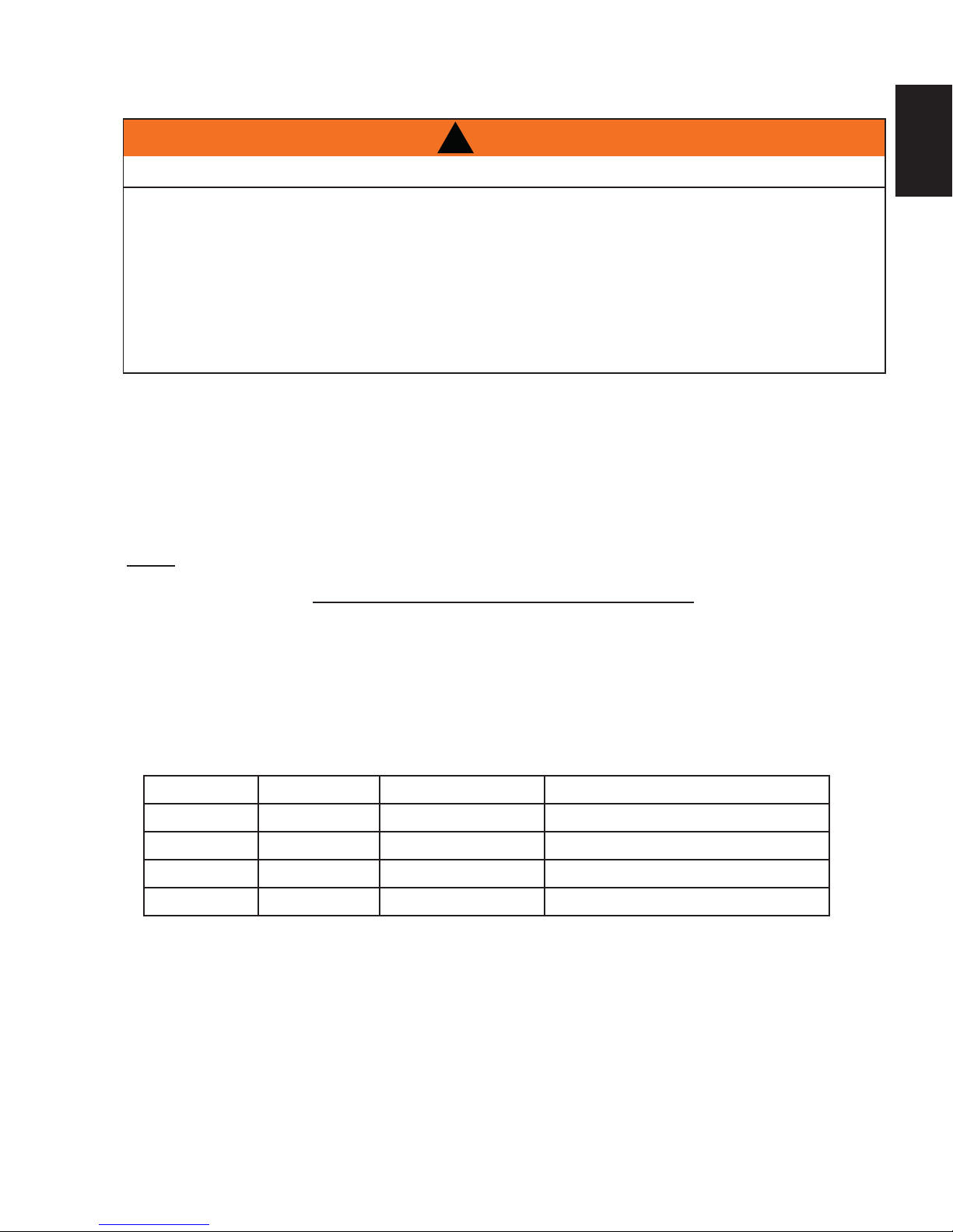
3.1 VENTING LENGTHS AND COMPONENTS
Use only Wolf Steel, Simpson Dura-Vent, Selkirk Direct Temp, American Metal Amerivent or Metal-Fab venting
components. Minimum and maximum vent lengths, for both horizontal and vertical installations, and air terminal
locations for either system are set out in this manual and must be adhered to. For Simpson Dura-Vent, Selkirk Direct
Temp, American Metal Amerivent and Metal-Fab follow the installation procedure provided with the venting components.
A starter adaptor must be used with the following vent systems and may be purchased from the corresponding supplier:
PART 4”/7” SUPPLIER WEBSITE
Duravent W175-0053 Wolf Steel www.duravent.com
Amerivent 4DSC-N2 American Metal www.americanmetalproducts.com
Direct Temp 4DT-AAN Selkirk www.selkirkcorp.com
SuperSeal 4DNA Metal-Fab www.mtlfab.com
For Simpson Dura-Vent, Selkirk Direct Temp, American Metal Amerivent and Metal-Fab follow the installation
procedure found on the website for your venting supplier.
For vent systems that provide seals on the inner exhaust fl ue, only the outer air intake joints must be sealed using a red
high temperature silicone (RTV). This same sealant may be used on both the inner exhaust and outer intake vent pipe
joints of all other approved vent systems except for the exhaust vent pipe connection to the appliance fl ue collar which must
be sealed using the black high temperature sealant Mill Pac. High temperature sealant must be ordered separately.
When using Wolf Steel venting components, use only approved Wolf Steel rigid / fl exible components with the following
termination kits: wall terminal kit GD222, GD222R, or 1/12 to 7/12 pitch roof terminal kit GD110, 8/12 to 12/12 roof terminal
kit GD111, fl at roof terminal kit GD112 or periscope kit GD201 (for wall penetration below grade). With fl exible venting, in
conjunction with the various terminations, use either the 5 foot (1.5m) vent kit GD220 or the 10 foot (3.1m) vent kit GD330.
W415-1347 / A / 03.19.15
Page 10
10
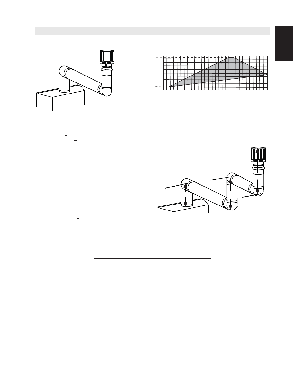
For optimum flame appearance and appliance performance, keep the vent length and number of elbows to a minimum.
The air terminal must remain unobstructed at all times. Examine the air terminal at least once a year to verify that
EN
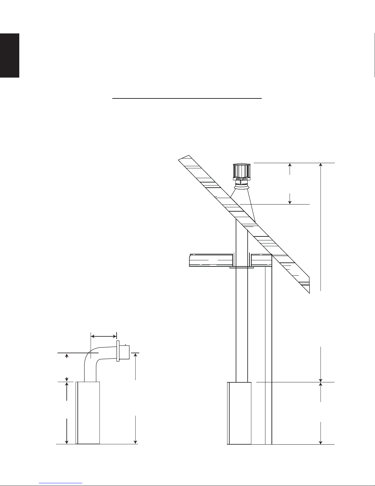
3.2 TYPICAL VENT INSTALLATIONS
it is unobstructed and undamaged.
Rigid and fl exible venting systems must not be combined. Different venting manufacturer components must not
be combined.
These vent kits allow for either horizontal or vertical venting of the appliance. The maximum allowable horizontal run is
20 feet (6.1m). The maximum allowable vertical vent length is 40 feet (12.2m). The maximum number of vent connections
is two horizontally or three vertically (excluding the appliance and the air terminal connections) when using fl exible venting.
Horizontal runs may have a 0” rise per foot however for optimum performance it is recommended that all
horizontal runs have a minimum 1/4" (6mm) rise per foot using fl exible or rigid venting. For safe and proper
operation of the appliance, follow the venting instructions exactly.
When terminating vertically, the vertical rise is a minimum 3 feet (1m) and a maximum 40 feet (12m) from the
top of the appliance.
8.1A
16" (406mm)
MIN
24" (610mm)
19 1/2" (495mm)
MIN
38"
(965mm)
* See “VENTING” section.
W415-1347 / A / 03.19.15-
MAX
57 1/2"
(1461mm)
MIN PLUS
RISE*
40FT (12m)
MAX
3FT (1m)
MIN
38"
(965mm)
Page 11
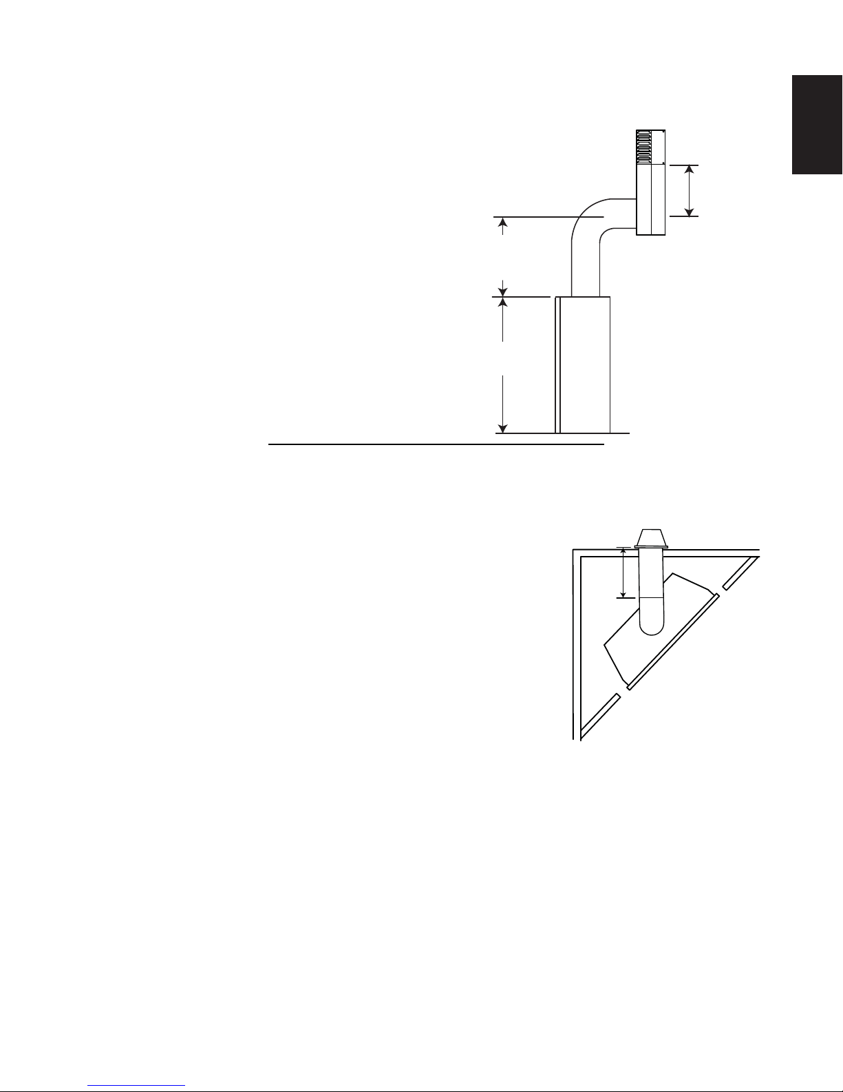
3.3 SPECIAL VENT INSTALLATIONS
11
3.3.1 PERISCOPE TERMINATION
Use the periscope kit to locate the air termination above grade. The periscope must
be installed so that when fi nal grading is completed, the bottom air slot is located a
minimum 12” (305m) above grade. The maximum allowable vent length is 10’ (3m)
for a fi replace and 8’ (2m) for a stove.
3.3.2 CORNER TERMINATION
The maximum vent length for a corner installation is 81 3/4" (2076mm) of
horizontal run with a minimum 19 1/2" (495mm) rise.
EN
12" (305mm)
MIN TO
GRADE
30"
(762mm)
MIN
38"
(965mm)
9.1B
20” (508mm)
MAX
W415-1347 / A / 03.19.15
Page 12
12
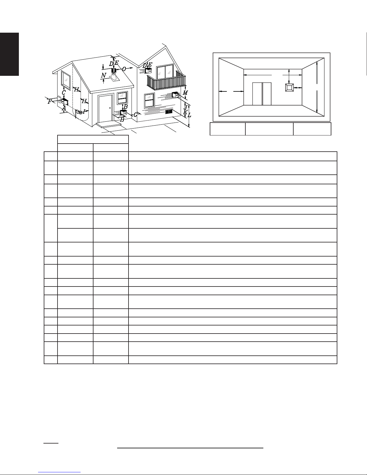
3.4 VENT TERMINAL CLEARANCES
EN
COVERED BALCONY APPLICATIONS ††*
Q
S
R
G
P
Q
= 3 feet
MIN
(0.9m)
R
MAX
INSTALLATIONS
CANADA U.S.A.
A 12” (305mm) 12” (305mm) Clearance above grade, veranda porch, deck or balcony.
B 12” (305mm)
Δ
9”
(229mm)
Clearance to windows or doors that open.
Δ
C 12” (305mm)* 12” (305mm) * Clearance to permanently closed windows.
D
18”
(457mm)**
18” (457mm)**
Vertical clearance to ventilated soffi ts located above the terminal within a horizontal distance of 2’
(0.6m) from the center line of the terminal.
E 12” (305mm)** 12” (305mm)** Clearance to unventilated soffi t.
F 0” (0mm) 0” (0mm) Clearance to an outside corner wall.
0” (0mm)***
G
2” (51mm)***
0”
(0mm)***
2”
(51mm)***
H 3’(0.9m) 3’ (0.9m)****
Clearance to an inside non-combustible corner wall or protruding non-combustible obstructions (chimney,
etc.).
Clearance to an inside combustible corner wall or protruding combustible obstructions (vent chase,
etc.).
Clearance to each side of the center line extended above the meter / regulator assembly to a
maximum vertical distance of 15’ (4.6m).
I 3’ (0.9m) 3’ (0.9m)**** Clearance to a service regulator vent outlet.
J 12” (305mm) 9” (229mm)
Clearance to a non-mechanical air supply inlet to the building or a combustion air inlet to any other
appliance.
K 6’ (1.8m) 3’ (0.9m) † Clearance to a mechanical air supply inlet.
L 7’ (2.1m) ‡ 7’ (2.1m) **** Clearance above a paved sidewalk or paved driveway located on public property.
M
12”
(305mm)††
12”
(305mm)****
Clearance under a veranda, porch or deck.
N 16” (406mm) 16” (406mm) Clearance above the roof.
O 2’ (0.6m)†* 2’ (0.6m) †* Clearance from an adjacent wall including neighbouring buildings.
P 8’ (2.4m) 8’(2.4m) Roof must be non-combustible without openings.
Q 3’ (0.9m) 3’ (0.9m) See chart for wider wall dimensions.
R 6’ (1.8m) 6’ (1.8m)
See chart for deeper wall dimensions. The terminal shall not be installed on any wall that has an
opening between the terminal and the open side of the structure.
S 12” (305mm) 12” (305mm) Clearance under a covered balcony
The terminal shall not be located less than 6 feet under a window that opens on a horizontal plane in a structure with three walls and a roof.
Δ
* Recommended to prevent condensation on windows and thermal breakage
** It is recommended to use a heat shield and to maximize the distance to vinyl clad soffi ts.
*** The periscope requires a minimum 18 inches clearance from an inside corner.
**** This is a recommended distance. For additional requirements check local codes.
† 3 feet above if within 10 feet horizontally.
‡ A vent shall not terminate where it may cause hazardous frost or ice accumulations on adjacent property surfaces.
†† Permitted only if the veranda, porch, or deck is fully open on a minimum of two sides beneath the fl oor.
†* Recommended to prevent recirculation of exhaust products. For additional requirements check local codes.
††* Permitted only if the balcony is fully open on a minimum of one side.
NOTE: Clearances are in accordance with local installation codes and the requirements of the gas supplier.
W415-1347 / A / 03.19.15-
= 2 x
12.1D
Q
ACTUAL
R
MAX
IHHW
(4.6m)
Page 13
3.5 VENT APPLICATION FLOW CHART
13
Horizontal Termination
Vertical rise is equal
to or greater than
the horizontal run
Horizontal run +
vertical rise to
maximum of 40 feet
(12m)
3.6 DEFINITIONS
For the following symbols used in the venting calculations and examples are:
> - greater than
> - equal to or greater than
< - less than
< - equal to or less than
HT - total of both horizontal vent lengths (Hr) and offsets (Ho) in feet
HR - combined horizontal vent lengths in feet
HO - offset factor: .03 (total degrees of offset - 90°*) in feet
VT - combined vertical vent lengths in feet
TOP EXIT
Vertical rise is less
than horizontal run
Horizontal run +
vertical rise to
maximum of
24.75 feet (7.5m)
4.2 times the
vertical rise equal to
or greater than the
horizontal run
Vertical Termination
Vertical rise is equal
to or greater than
the horizontal run
Horizontal run +
vertical rise to
maximum of 40 feet
(12m)
EN
Vertical rise is less
than horizontal run
Horizontal run +
vertical rise to
maximum of 40 feet
(12m)
3 times the vertical
rise equal to or
greater than the
horizontal run
13.1A
14.1
3.7 ELBOW VENT LENGTHS
FEET INCHES MILLIMETERS
1° 0.03 0.5 12.7
15° 0.45 6.0 152.4
30° 0.9 11.0 279.4
45° 1.35 16.0 406.4
90°* 2.7 32.0 812.8
* The fi rst 90° offset has a zero value and is shown in the formula as - 90°
15.1A
W415-1347 / A / 03.19.15
Page 14
14
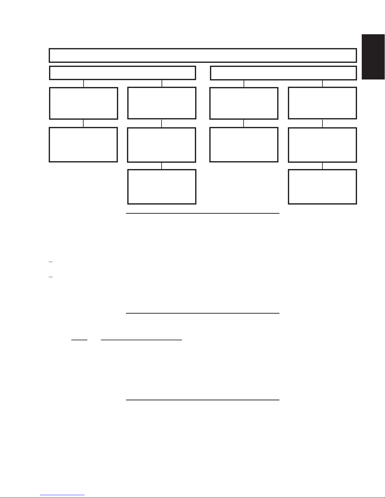
3.8 HORIZONTAL TERMINATION
EN
(HT) < (VT)
Simple venting confi guration (only one 90° elbow)
See graph to determine the required vertical
rise VT for the required horizontal run HT.
40 (12.2)
39 (11.9)
REQUIRED
30 (9.1)
VERTICAL
RISE IN FEET
20 (6.1)
(METERS)VT
10 (3.1)
0
2.5
(0.8)5(1.5)
7.5
(2.3)
10
(3.1)
12.5
(3.8)15(4.6)
HORIZONTAL VENT RUN PLUS OFFSET IN
FEET (METERS) H
T
The shaded area within the lines represents
acceptable values for HT and V
For vent confi gurations requiring more than one 90° elbow, the following formulas apply:
Formula 1: HT < V
T
Formula 2: HT + VT < 40 feet (12.2m)
17.5
(5.3)20(6.1)
T
Example:
V1 = 3 FT (0.9m)
V2 = 8 FT (2.4m)
VT = V1 + V2= 3 FT (0.9m ) + 8 FT (2.4m) = 11 FT (3.4m)
H1 = 2.5 FT (0.8m)
H2 = 2 FT (0.6m)
HR = H1 + H2 = 2.5 FT (0.8m) + 2 FT (0.6m) = 4.5 FT (1.4m)
HO = .03 (three 90° elbows - 90°) = .03 (270° - 90°) = 5.4 FT (1.7m)
HT = HR + HO = 4.5 FT (1.4m) + 5.4 FT (1.6m) = 9.9 FT (3m)
HT + VT = 9.9 FT (3m) + 11 FT (3.4m) = 20.9 FT (6.4m)
Formula 1: HT < V
T
9.9 FT (3m) < 11 FT (3.4m)
Formula 2: HT + VT < 40 FT (12.2m)
20.9 FT (6.4m) < 40 FT (12.2m)
Since both formulas are met, this vent confi guration is acceptable.
90°
V
90°
1
16.1B
90°
H
2
V
2
H
1
W415-1347 / A / 03.19.15-
Page 15
15
V
V
V
V
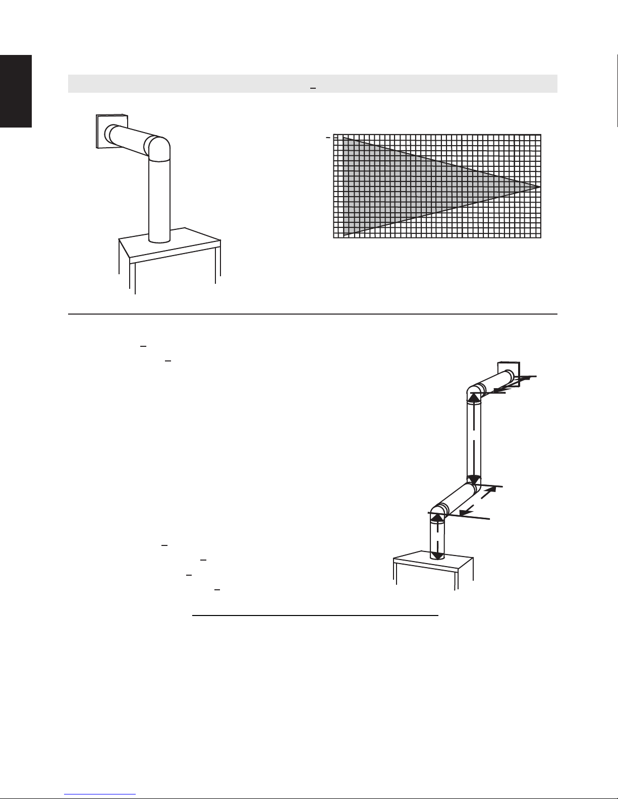
(HT) > (VT)
Simple venting configuration (only one 90° elbow)
REQUIRED
VERTICAL RISE
See graph to determine the required vertical rise VT for the
150 (3810)
(3733.8)
(3733.8)
100 (2540)
required horizontal run H
150 (3810)
147
147
100 (2540)
.
T
EN
IN INCHES
(MILLIMETERS)
V
T
HORIZONTAL VENT RUN PLUS OFFSET IN FEET (METERES) H
57 (1447.8)
57 (1447.8)
19 1/2
19 1/2
(495.3)
(495.3)
50 (1270)
50 (1270)
5
0
5
0
(1.5)
2
(1.5)
2
(0.6)
(0.6)
(3.1)
(3.1)
15
10
10
12.5
12.5
(3.8)
(3.8)
(4.6)
(4.6)
20 (6.1)
15
20 (6.1)
19.5
19.5
(5.9)
(5.9)
T
The shaded area within the lines represents acceptable
values for HT and VT
For vent configurations requiring more than one 90° elbow, the following formulas apply:
< 4.2 V
Formula 1:
Formula 2: HT + V
Example:
= VT = 6 FT (1.8m)
1
H
= 3 FT (0.9m)
1
H
= 5 FT (1.5m)
2
H
= H
R
HO = .03 (two 90° elbows - 90°) = .03 (180° - 90°) = 2.7FT (0.8m)
H
= H
T
H
+ V
T
H
T
+ H
= 3FT (0.9m) + 5FT (1.5m) = 8 FT (2.4m)
1
2
+ H
= 8FT (2.4m) + 2.7FT (0.8m) = 10.7FT (3.3m)
R
O
= 10.7FT (3.3m) + 6FT (1.8m) = 16.7FT (5.1m)
T
T
< 24.75 feet (7.5m)
T
90°
V
1
H
1
H
2
90°
Formula 1: HT < 4.2 V
4.2 VT = 4.2FT (1.3m) x 6FT (1.8m) = 25.2FT (7.7m)
10.7FT (3.3m) < 25.2FT (7.7m)
Formula 2: HT + V
16.7FT (5.1m) < 24.75 (7.5m)
Since both formulas are met, this vent configuration is acceptable.
Example:
= 4 FT (1.2m)
1
= 1.5 FT (0.5m)
2
= V
+ V
T
H
= 2 FT (0.6m)
1
H
= 1 FT (0.3m)
2
H
= 1 FT (0.3m)
3
H
= 1.5 FT (0.5m)
4
H
= H
R
H
= .03 (four 90° elbows - 90°) = .03 (360° - 90°) = 8.1 FT (2.5m)
O
H
= H
T
H
+ V
T
= 4FT (1.2m) + 1.5FT (0.5m) = 5.5 FT (1.7m)
1
2
+ H2 + H
1
+ H
= 5.5 FT (1.7m) + 8.1 FT (2.5m) = 13.6 FT (4.2m)
R
O
= 13.6 FT (4.2m) + 5.5 FT (1.7m) = 19.1 FT (5.8m)
T
Formula 1: HT < 4.2 V
4.2 VT = 4.2 FT (1.3m) x 5.5 FT(1.7m) = 23.1 FT (7m)
T
< 24.75 FT (7.5m)
T
90°
H
1
90°
V
1
+ H4 = 2FT (0.6m) + 1FT (0.3m) + 1FT (0.3m) + 1.5FT (0.5m) = 5.5 FT (1.7m)
3
T
90°
90°
H
V
2
H
H
2
3
4
13.6 FT (4.2m) < 23.1 FT (7m)
Formula 2: HT + V
19.1FT (5.8m) < 24.75 FT (7.5m)
< 24.75 FT (7.5m)
T
Since both formulas are met, this vent configuration is acceptable.
16.1_2A
W415-1347 / A / 03.19.15
Page 16
16
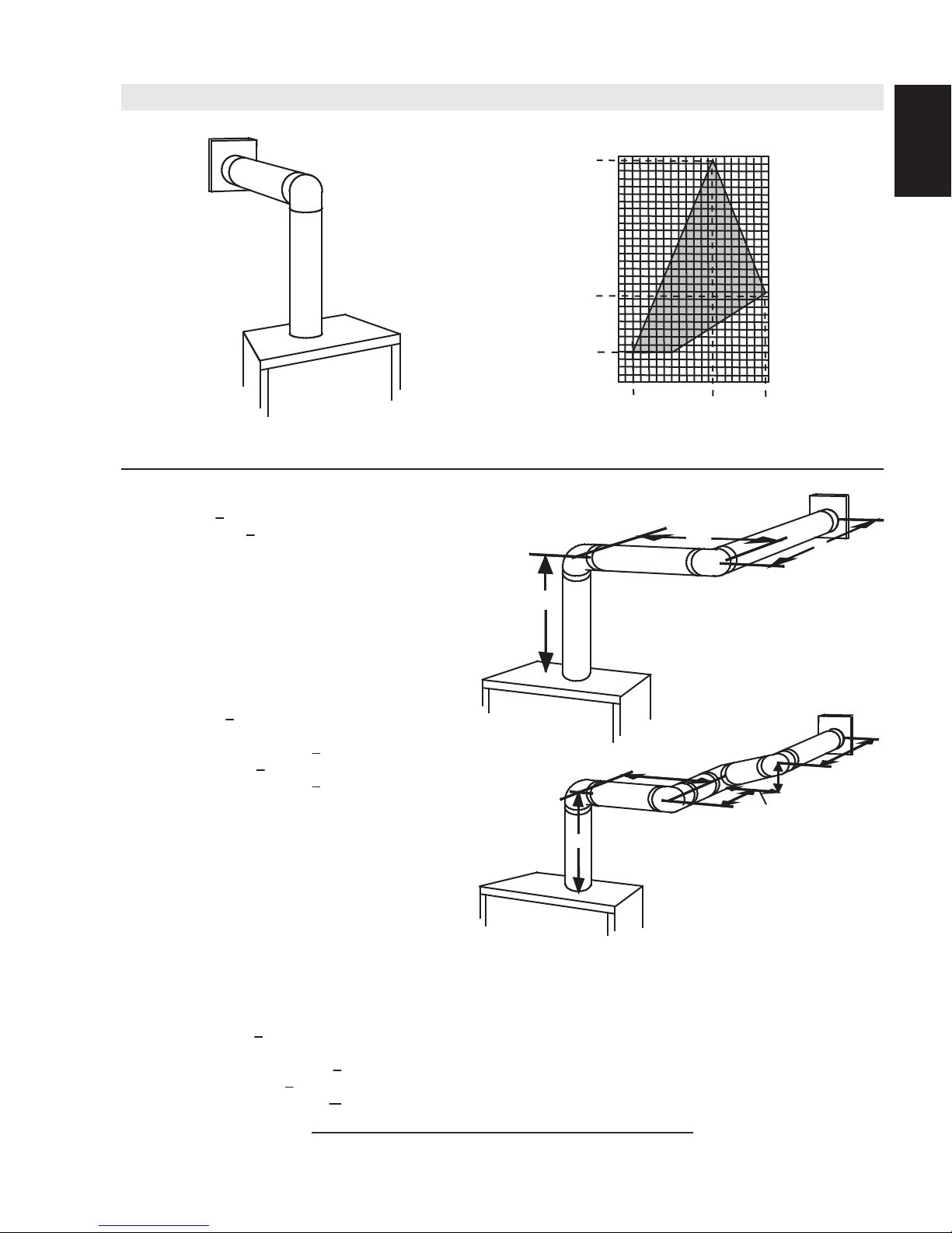
3.9 VERTICAL TERMINATION
EN
(HT) < (VT)
Simple venting configurations.
See graph to determine the required vertical rise V
required horizontal run HT.
40 (12.2)
30 (9.1)
REQUIRED
VERTICAL
RISE IN FEET
(METERS) V
T
3 (0.9)
20 (6.1)
10 (3.1)
0
5
(1.5)
HORIZONTAL VENT RUN PLUS OFFSET IN FEET (METERS) H
The shaded area within the lines represents acceptable
values for HT and VT
For vent configurations requiring one or more 90° elbows the following formulas apply:
Formula 1: H
Formula 2: HT + V
< V
T
T
< 40 feet (12.2m)
T
10
(3.1)
15
(4.6)
20
(6.1)
for the
T
T
Example:
V
= 5 FT (1.5m)
1
V
= 6 FT (1.8m)
2
V
= 10 FT (3.1m)
3
V
= V
+ V2 + V3 = 5FT (1.5m) + 6FT (1.8m) + 10FT (3.1m) = 21FT (6.4m)
T
1
H
= 8 FT (2.4m)
1
H
= 2.5 FT (0.8m)
2
H
= H
+ H
R
H
= .03 (four 90° elbows - 90°)
O
= .03 (360° - 90°) = 8.1 FT (2.5m)
H
= H
T
H
+ V
T
Formula 1: HT < V
18.6FT (5.7m) < 21FT (6.4m)
Formula 2: HT + V
39.6FT (12.1m) < 40FT (12.2m)
= 8FT (2.4m) + 2.5FT (0.8m) = 10.5 FT (3.2m)
1
2
+ H
= 10.5FT (3.2m) + 8.1FT (2.5m) = 18.6FT (5.7m)
R
O
= 18.6FT (5.7m) + 21FT (6.4m) = 39.6FT (12.1m)
T
T
< 40 FT (12.19m)
T
Since both formulas are met, this vent configuration is acceptable.
90°
V
3
90°
H
2
V
H
1
V
1
2
90°
90°
18.1A
W415-1347 / A / 03.19.15-
Page 17
17
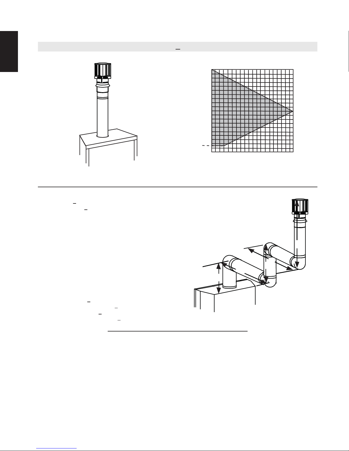
Simple venting configurations.
(HT) > (VT)
20 (6.1)
19 (5.8)
See graph to determine the required vertical rise V
required horizontal run H
.
T
for the
T
REQUIRED
VERTICAL
RISE IN FEET
(METERS) V
T
3 (0.9)
10 (3.1)
0
5
(1.5)
10
(3.1)
15
(4.6)
20
(6.1)
25
(7.6)
(9.1)
HORIZONTAL VENT RUN PLUS OFFSET IN FEET (METERS) H
The shaded area within the lines represents acceptable
values for H
and VT
T
For vent configurations requiring more than two 90° elbows the following formulas apply:
Formula 1: H
Formula 2: HT + V
< 3V
T
T
< 40 feet (12.2m)
T
Example:
V
= 2 FT (0.6m)
1
V
= 1 FT (0.3m)
2
V
= 1.5 FT (0.5m)
3
V
= V1+V2+V3= 2FT (0.6m) + 1FT (0.3m) + 1.5FT (0.5m) = 4.5FT (1.4m)
T
H
= 6 FT (1.8m)
1
H
= 2 FT (0.6m)
2
H
= H
+ H
R
H
= .03 (four 90° elbows - 90°)
O
= .03 (360° - 90°) = 8.1 FT (2.5m)
H
= H
T
H
+ V
T
= 6FT (1.8m) + 2FT (0.6m) = 8 FT (2.4m)
1
2
+ H
= 8FT (2.4m) + 8.1FT (2.5m) = 16.1FT (4.9m)
R
O
= 16.1FT (4.9m) + 4.5FT (1.4m) = 20.6 FT (6.3m)
T
90°
H
V
1
1
90°
V
H
2
V
2
3
90°
90°
Formula 1: HT < 3V
3VT = 3FT (0.9m) x 4.5FT (1.4m) = 13.5FT (4.1m)
T
16.1FT (4.9m) > 13.5FT (4.1m)
Since this formula is not met, this vent configuration is unacceptable.
Formula 2: HT + VT < 40 feet (12.2m)
20.6FT (6.3m) < 40 (12.2m)
Since only formula 2 is met, this vent configuration is unacceptable and a new appliance location or vent configuration will
need to be established to satisfy both formulas.
18.1_2B
T
EN
30
W415-1347 / A / 03.19.15
Page 18
18
AIR
INTAKE
EXHAUST
FLUE
FLEX
LINER
* 40 FT (12.2m)
MAX.
10 FT (3.1m)
MIN
COAXIAL TO
CO-LINEAR
ADAPATOR
APPLIANCE
VENT ADAPTOR
TERMINATION
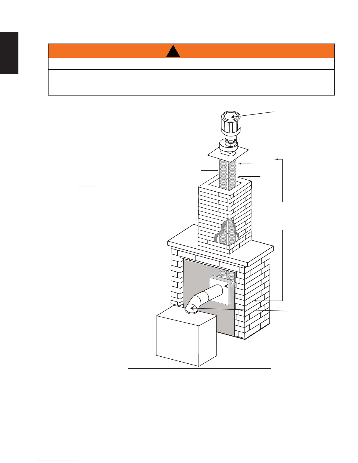
3.10 CO-AXIAL TO CO-LINEAR VENTING
EN
!
WARNING
RISK OF FIRE!
CO-AXIAL TO CO-LINEAR VENTING CONFIGURATIONS MUST ONLY BE USED IN A NON-
COMBUSTIBLE CHIMNEY OR ENCLOSURE. INSTALLATION IN A COMBUSTIBLE ENCLOSURE COULD
RESULT IN A FIRE.
This appliance is designed to be attached to a 3” (76.2mm) co-linear aluminum fl ex vent system running the
full length of a masonry chimney.
The fl ex liners accommodate any contours of a
masonry chimney, however, it is necessary to keep
the fl exible liners as straight as possible. The inlet air
collar of the termination cap must be connected to
the air intake fl ex liner and the exhaust collar must be
connected to the exhaust fl exible liner.
Both Simpson Duravent and Selkirk co-linear to
co-axial adaptors have been approved on this
appliance (NOTE: A vent adaptor will be required
directly off the appliance).
Follow vent manufacturer’s installation instructions.
Different manufacturer’s venting components must
not be combined. Once the preferred manufacturer’s
appliance adaptor has been attached, the
remainder of the system must be that of the
same manufacturer.
The only exception to this rule is to use Wolf
Steel’s approved 3” (76.2mm) fl ex liner and
co-linear termination.
* Measured from appliance fl ue collar to
termination fl ue collar
7.6A
W415-1347 / A / 03.19.15-
Page 19
4.0 INSTALLATION
!
WARNING
ENSURE TO UNPACK ALL LOOSE MATERIALS FROM INSIDE THE FIREBOX PRIOR TO HOOKING UP
IF YOUR APPLIANCE IS SUPPLIED WITH A REMOTE ENSURE THE REMOTE RECEIVER IS IN THE
“OFF” POSITION PRIOR TO HOOKING UP THE GAS AND ELECTRICAL SUPPLY TO THE APPLIANCE.
FOR SAFE AND PROPER OPERATION OF THE APPLIANCE, FOLLOW THE VENTING INSTRUCTIONS
ALL INNER EXHAUST AND OUTER INTAKE VENT PIPE JOINTS MAY BE SEALED USING EITHER RED
RTV HIGH TEMP SILICONE SEALANT W573-0002 (NOT SUPPLIED) OR BLACK HIGH TEMP MILL PAC
W573-0007 (NOT SUPPLIED) WITH THE EXCEPTION OF THE APPLIANCE EXHAUST FLUE COLLAR
IF USING PIPE CLAMPS TO CONNECT VENT COMPONENTS, 3 SCREWS MUST ALSO BE USED TO
RISK OF FIRE, EXPLOSION OR ASPHYXIATION. IMPROPER SUPPORT OF THE ENTIRE VENTING
SYSTEM MAY ALLOW VENT TO SAG AND SEPARATE. USE VENT RUN SUPPORTS AND CONNECT
VENT SECTIONS PER INSTALLATION INSTRUCTIONS.
THE GAS AND ELECTRICAL SUPPLY.
EXACTLY.
WHICH MUST BE SEALED USING MILL PAC.
ENSURE THE CONNECTION CANNOT SLIP OFF.
DO NOT CLAMP THE FLEXIBLE VENT PIPE.
19
EN
RISK OF FIRE, DO NOT ALLOW LOOSE MATERIALS OR INSULATION TO TOUCH THE VENT PIPE.
REMOVE INSULATION TO ALLOW FOR THE INSTALLATION OF THE ATTIC SHIELD AND TO
MAINTAIN CLEARANCES TO COMBUSTIBLES.
68.2B
4.1 WALL AND CEILING PROTECTION
!
WARNING
DO NOT FILL THE SPACE BETWEEN THE VENT PIPE AND ENCLOSURE WITH ANY TYPE OF
MATERIAL. DO NOT PACK INSULATION OR COMBUSTIBLES BETWEEN CEILING FIRESTOPS.
ALWAYS MAINTAIN SPECIFIED CLEARANCES AROUND VENTING AND FIRESTOP SYSTEMS.
INSTALL WALL SHIELDS AND FIRESTOPS AS SPECIFIED. FAILURE TO KEEP INSULATION OR
OTHER MATERIALS AWAY FROM VENT PIPE MAY CAUSE FIRE.
70.1
For optimum performance it is recommended that all horizontal runs have a minimum of 1/4' (6m) rise per foot
using fl exible venting. For safe and proper operation of the appliance, follow the venting instructions exactly.
W415-1347 / A / 03.19.15
Page 20
20
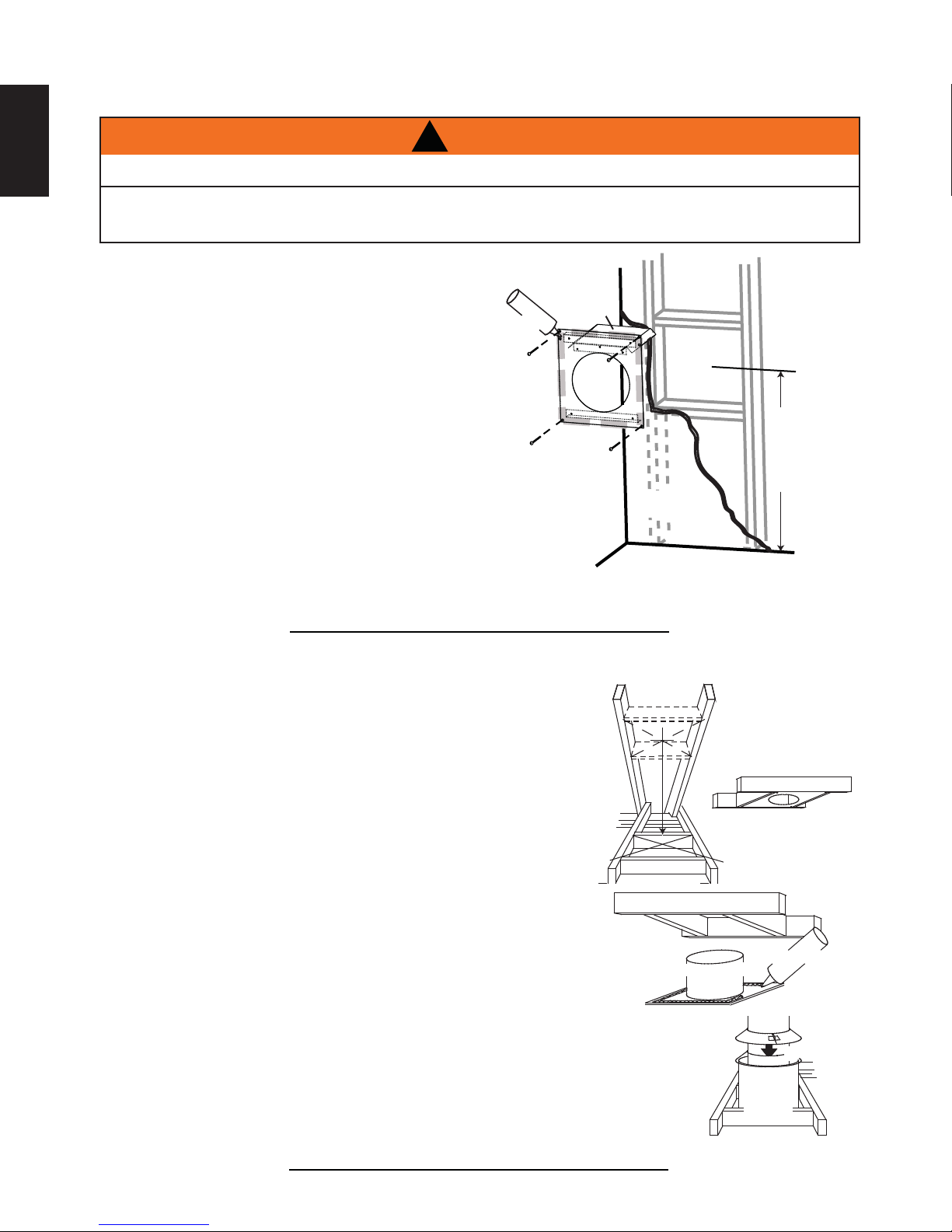
4.1.1 HORIZONTAL INSTALLATION
EN
THE FIRESTOP ASSEMBLY MUST BE INSTALLED WITH THE VENT SHIELD TO THE TOP.
TERMINALS MUST NOT BE RECESSED INTO A WALL OR SIDING MORE THAN THE DEPTH OF THE
This application occurs when venting through an exterior wall.
Having determined the correct height for the air terminal
location, cut and frame a hole in the exterior wall as
illustrated to accommodate the fi restop assembly.
Dry fi t the fi restop assembly before proceeding to
ensure the brackets on the rear surface fi t to the
inside surface of the horizontal framing.
The length of the vent shield may be cut shorter
for combustible walls that are less than 8 1/2”
(215.9mm) thick but the vent shield must extend
the full depth of the combustible wall.
A. Apply a bead of caulking (not supplied) around the corner edge of
the inside surface of the fi restop assembly, fi t the fi restop
assembly to the hole and secure using the 4 screws (supplied in your
manual baggie).
B. Once the vent pipe is installed in its fi nal position, apply high temperature sealant W573-0007 (not
supplied) between the pipe and the fi restop.
4.1.2 VERTICAL INSTALLATION
!
WARNING
RETURN FLANGE OF THE MOUNTING PLATE.
VENT
CAULKING
FIRESTOP
SPACER
SHIELD
FINISHING
MATERIAL
DETERMINE
THE
CORRECT
HEIGHT
20.2A
This application occurs when venting through a roof. Installation kits for
various roof pitches are available from your authorized dealer / distributor.
See accessories to order specifi c kits required.
A. Determine the air terminal location, cut and frame a square opening as
illustrated in the ceiling and the roof to provide the minimum 1” (25mm)
clearance between the vent pipe and any combustible material. Try to center
the vent pipe location midway between two joists to prevent having to cut
them. Use a plumb bob to line up the center of the openings. A vent pipe
shield will prevent any materials such as insulation, from fi lling up the 1”
(25mm) air space around the pipe. Nail headers between the joist for
extra support.
B. Apply a bead of caulking (not supplied) to the framework or to the Wolf
Steel vent pipe shield plate or equivalent (in the case of a fi nished ceiling),
and secure over the opening in the ceiling. A fi restop must be placed on the
bottom of each framed opening in a roof or ceiling that the venting system passes
through. Apply a bead of caulking all around and place a fi restop spacer over
the vent shield to restrict cold air from being drawn into the room or around the
fi replace. Ensure that both spacer and shield maintain the required clearance to
combustibles. Once the vent pipe is installed in its fi nal position, apply sealant between the
pipe and the fi restop assembly.
C. In the attic, slide the vent pipe collar down to cover up the open end of the shield and
tighten. This will prevent any materials, such as insulation, from fi lling up the 1” (25mm) air
space around the pipe.
W415-1347 / A / 03.19.15-
9 3/4”
(248mm)
FIRESTOP
UNDERSIDE OF
JOIST
VENT PIPE
SHIELD
SHIELD
21.1
9 3/4”
(248mm)
CAULKING
VENT
PIPE
COLLAR
VENT
PIPE
Page 21
4.2 USING FLEXIBLE VENT COMPONENTS
21
!
WARNING
DO NOT ALLOW THE INNER FLEX PIPE TO BUNCH UP ON HORIZONTAL OR VERTICAL RUNS AND ELBOWS.
KEEP IT PULLED TIGHT.
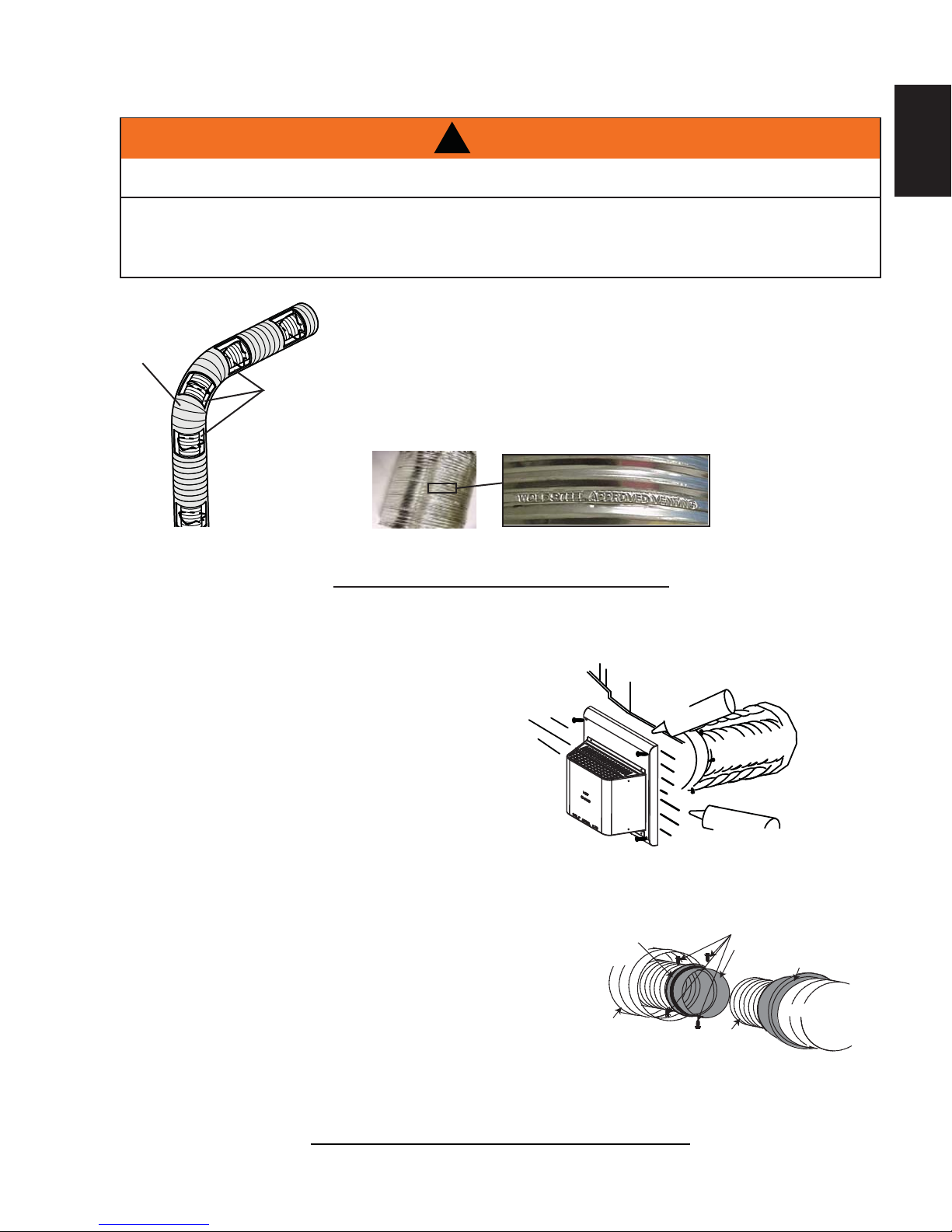
SPACERS ARE ATTACHED TO THE INNER FLEX PIPE AT PREDETERMINED INTERVALS TO MAINTAIN AN EVEN
AIR GAP TO THE OUTER FLEX PIPE. THIS GAP IS REQUIRED FOR SAFE OPERATION. A SPACER IS REQUIRED
AT THE START, MIDDLE AND END OF EACH ELBOW TO ENSURE THIS GAP IS MAINTAINED. THESE SPACERS
MUST NOT BE REMOVED.
For safe and proper operation of the appliance, follow the venting
instructions exactly.
All inner fl ex pipe and outer fl ex pipe joints may be sealed using high
ELBOW
SPACERS
temperature sealant W573-0002 (not supplied) or the high temperature
sealant W573-0007 Mill Pac (not supplied). However, the high temperature
sealant W573-0007 Mill Pac (not supplied) must be used on the joint
connecting the inner fl ex pipe and the exhaust fl ue collar.
Use only approved fl exible vent pipe kits marked:
“Wolf Steel Approved Venting” as identifi ed
by the stamp only on the outer fl ex pipe.
22.1
EN
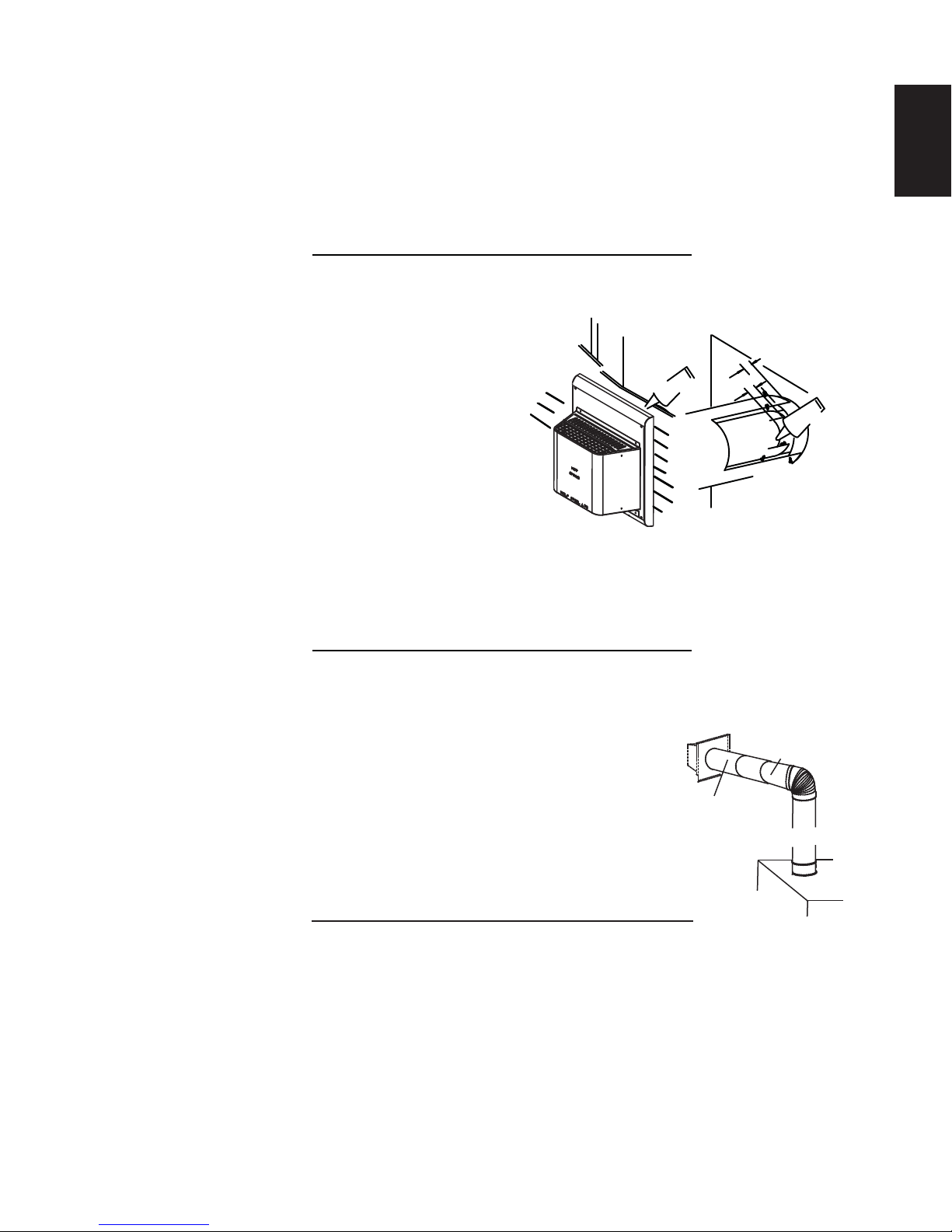
4.2.1 HORIZONTAL AIR TERMINAL INSTALLATION
A. Stretch the inner fl ex pipe to the required length taking into
account the additional length needed for the fi nished wall
surface. Apply a heavy bead of the high temperature
sealant W573-0007 Mill Pac (not supplied) to the inner
sleeve of the air terminal. Slip the vent pipe a minimum
of 2” (50.8mm) over the inner sleeve of the air terminal
and secure with 3 #8 screws.
B. Using the outer fl ex pipe, slide over the outer combustion
air sleeve of the air terminal and secure with 3 #8 screws.
Seal using high temperature sealant W573-0002 (not
supplied).
C. Insert the vent pipes through the fi restop maintaining the required
clearance to combustibles. Holding the air terminal (lettering in
an upright, readable position), secure to the exterior wall and
make weather tight by sealing with caulking (not supplied).
D. If more vent pipe needs to be used to reach the fi replace, couple
them together as illustrated. The vent system must be
supported approximately every 3 feet (0.9m) for both vertical
and horizontal runs. Use noncombustible strapping to
maintain the minimum clearance to combustibles.
SCREWS
HI-TEMP
SEALANT
FLEX PIPE
#10x2"
OUTER
CAULKING
INNER FLEX
PIPE
2" (50.8mm) OVERLAP
HIGH TEMPERATURE
#8 X 1/2” SELF DRILLING
INNER
FLEX PIPE
OUTER FLEX PIPE
SEALANT
SCREWS
INNER COUPLER
OUTER COUPLER
OUTER
FLEX PIPE
The air terminal mounting plate may be recessed into the exterior wall or siding no greater than the depth
of its return fl ange.
23.1B
W415-1347 / A / 03.19.15
Page 22
22
4.2.2 VERTICAL AIR TERMINAL INSTALLATION
EN
!
WARNING
MAINTAIN A MINIMUM 2” (51mm) SPACE BETWEEN THE AIR INLET BASE AND THE STORM COLLAR.
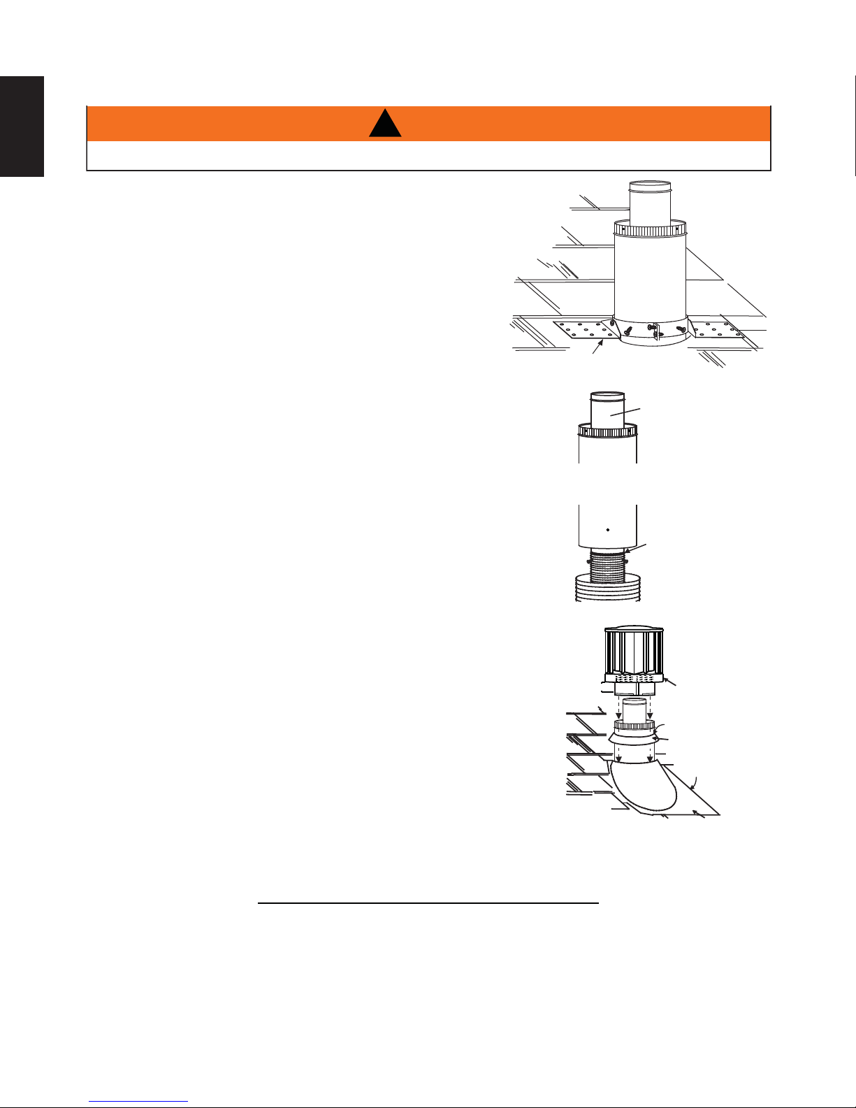
A. Fasten the roof support to the roof using the screws provided. The
roof support is optional. In this case the venting is to be adequately
supported using either an alternate method suitable to the authority
having jurisdiction or the optional roof support.
B. Stretch the inner fl ex pipe to the required length. Slip the
inner fl ex pipe a minimum of 2” (51mm) over the inner pipe
of the air terminal connector and secure with 3 #8 screws.
Seal using a heavy bead of high temperature sealant
W573-0007 (not supplied).
C. Repeat using the outer fl ex pipe, using a heavy bead of
high temperature sealant W573-0002 (not supplied).
D. Thread the air terminal connector / vent pipe assembly down through
the roof. The air terminal must be positioned vertically and plumb.
Attach the air terminal connector to the roof support, ensuring that the
top of the air terminal is 16” (406mm) above the highest point that it
penetrates the roof.
E. Remove nails from the shingles, above and to the sides of the air
terminal connector. Place the fl ashing over the air terminal connector
leaving a min. 3/4” (19mm) of the air terminal connector showing
above the top of the fl ashing. Slide the fl ashing underneath the
sides and upper edge of the shingles. Ensure that the air terminal
connector is properly centred within the fl ashing, giving a 3/4”
(19mm) margin all around. Fasten to the roof. Do not nail through
the lower portion of the fl ashing. Make weather-tight by sealing with
caulking. Where possible, cover the sides and top edges of the
fl ashing with roofi ng material.
F. Aligning the seams of the terminal and air terminal connector,
place the terminal over the air terminal connector making sure
the vent pipe goes into the hole in the terminal. Secure with
the three screws provided.
G. Apply a heavy bead of weatherproof caulking 2” (51mm) above
the fl ashing. Install the storm collar around the air terminal and
slide down to the caulking. Tighten to ensure that a weathertight seal between the air terminal and the collar is achieved.
ROOF SUPPORT
AIR
TERMINAL
CONNECTOR
2” (51mm)
INNER PIPE
HIGH
TEMPERATURE
SEALANT
INNER FLEX PIPE
OUTER FLEX PIPE
AIR I NL ET
BASE
CAULKING
STORM COLLAR
WEA THER
SEALANT
FLASHING
H. If more vent pipe needs to be used to reach the appliance see “HORIZONTAL
AIR TERMINAL INSTALLATION” section.
W415-1347 / A / 03.19.15-
24.1A
Page 23
4.3 USING RIGID VENT COMPONENTS
A
The vent system must be supported approximately every 3 feet (0.9m) for both vertical and horizontal runs.
Use Wolf Steel Ltd. support ring assembly or equivalent noncombustible strapping to maintain the minimum
clearance to combustibles for both vertical and horizontal runs.
ll inner exhaust and outer intake vent pipe joints may be sealed using either red high temperature silicone
sealant W573-0002 (not supplied) or black high temperature sealant W573-0007 Mill Pac (not supplied) with
the exception of the appliance exhaust fl ue collar which must be sealed using Mill Pac.
25.1A
4.3.1 HORIZONTAL AIR TERMINAL INSTALLATION
A. Move the appliance into position. Measure the
vent length required between terminal and
appliance taking into account the additional
length needed for the fi nished wall surface
and any 1¼” (31.8mm) overlaps between
venting components.
B. Apply high temperature sealant W573-0007 (not
supplied) to the outer edge of the inner exhaust fl ue
collar of the appliance. Attach the fi rst inner rigid
pipe component and secure using 3 self tapping
screws. Repeat using the outer rigid pipe.
#10x2"
SCREWS
CAULKING
OUTER
RIGID
PIPE
1" (25.4mm)
INNER
RIGID
PIPE
#8x1/2"
SELF DRILLING
SCREWS
23
EN
OVERLAP
HI-TEMP
SEALANT
C. Insert the vent pipes through the fi restop maintaining the required clearance to combustibles. Holding
the air terminal (lettering in an upright, readable position), secure to the exterior wall and make
weather tight by sealing with caulking (not supplied).
The air terminal mounting plate may be recessed into the exterior wall or siding no greater than the
depth of the return fl ange.
26.1A
4.3.2 EXTENDED HORIZONTAL AIR TERMINAL INSTALLATION
A. Follow the instructions for "HORIZONTAL AIR TERMINAL INSTALLATIONS" section.
B.
Continue adding components alternating inner rigid pipe and outer rigid pipe. Ensure
that all inner rigid pipe and elbows have sufficient vent spacers attached and each
component is sealed and securely fastened to the one prior. Attach the inner telescopic
sleeve to the vent run. Repeat using the outer telescopic sleeve. Seal and secure as
before. To facilitate completion, attach inner and outer couplers to the air terminal.
C. Install the air terminal. See “HORIZONTAL AIR TERMINAL INSTALLATION” section.
AIR TERMINAL
20" (508mm)
COUPLER
VENTING
48.1A
TELESCOPIC
SLEEVE
W415-1347 / A / 03.19.15
Page 24
24
VENT
PIPE
COLLAR
VENT
PIPE
SHIELD
4.3.3 VERTICAL VENTING INSTALLATION
EN
A. Move the appliance into position.
B. Fasten the roof support to the roof using the screws provided. The
roof support is optional. In this case the venting is to be adequately
supported using either an alternate method suitable to the authority
having jurisdiction or the optional roof support.
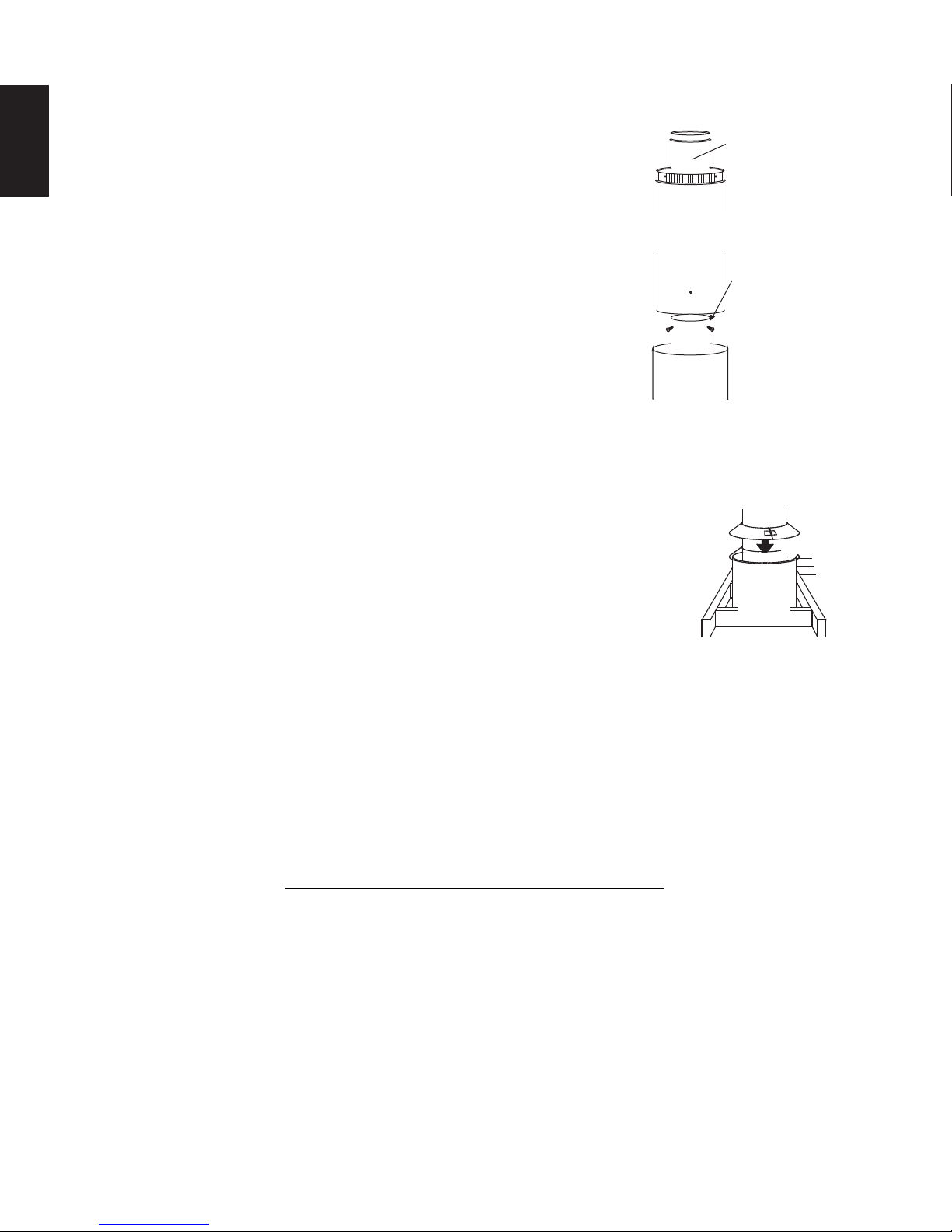
C. Apply high temperature sealant (not supplied) to the outer edge of
the inner sleeve of the air terminal. Slip the inner coupler a minimum
of 2" (51mm)over the sleeve and secure using 3 screws.
D. Apply high temperature sealant (not supplied) to the outer edge of
the of the outside sleeve of the air terminal connector. Slip the outer
coupler over the sleeve and secure as before. Trim the outer coupler
even with the inner coupler end.
E. Thread the air terminal connector / vent pipe assembly down through
the roof support and attach, ensuring that a minimum 16" (406mm)
of air terminal connector will penetrate the roof when fastened. If
the attic space is tight, we recommend threading the Wolf Steel vent pipe collar or equivalent loosely
onto the air terminal connector / vent pipe assembly as it is passed through the attic. The air terminal
connector must be located vertically and plumb.
F. Remove nails from the shingles, above and to the sides of the air terminal
connector. Place the fl ashing over the air terminal connector and slide it
underneath the sides and upper edge of the shingles. Ensure that the air
terminal connector is properly centered within the fl ashing, giving a 3/4"
(19mm) margin all around. Fasten to the roof. Do NOT nail through the lower
portion of the fl ashing. Make weather-tight by sealing with caulking. Where
possible, cover the sides and top edges of the fl ashing with roofi ng material.
G. Apply a heavy bead of waterproof caulking 2" (51mm) above the fl ashing.
Install the storm collar around the air terminal and slide down to the caulking. Tighten to ensure that a
weather-tight seal between the air terminal connector and the collar is achieved.
H. Continue adding rigid venting sections, sealing and securing as above. Attach the inner collapsed
telescopic sleeve to the last section of rigid piping. Secure with screws and seal. Repeat using the
outer telescopic sleeve.
I. Run a bead of high temperature sealant (not supplied) around the outside of the inner exhaust fl ue
collar on the appliance. Pull the telescopic sleeve a minimum of 2" (51mm) onto the collar. Secure with
3 screws. Repeat with the outer telescopic sleeve.
J. In the attic, slide the vent pipe collar down to cover up the open end of the shield and tighten. This will
prevent any materials, such as insulation, from fi lling up the 1" (25mm) air space around the pipe.
AIR
TERMINAL
CONNECTOR
INNER PIPE
HIGH
TEMPERATURE
SEALANT
INNER RIGID
PIPE
OUTER
RIGID PIPE
W415-1347 / A / 03.19.15-
27.2A
Page 25
4.4 MOBILE HOME
A
25
This appliance is also certifi ed to be installed as an OEM (Original Equipment Manufacturer) installation
in a manufactured home (U.S. only) or mobile home and must be installed in accordance with the
manufacturer’s instructions and the Manufactured Home Construction and Safety Standard, Title 24 CFR,
Part 3280, in the United States or the Mobile Home Standard, CAN/CSA Z240 MH Series, in Canada. This
appliance is only for use with the type(s) of gas indicated on the rating plate.
This Mobile/Manufactured Home Listed appliance comes factory equipped with a means to secure the unit. Built
in appliances are equipped with 1/4” (6.4mm) diameter holes located in the front left and right corners of the
base. Use #10 hex head screws, inserted through the holes in the base to secure. For free standing products
contact your local authorized dealer / distributor for the appropriate securing kit. For mobile home installations, the
appliance must be fastened in place. It is recommended that the appliance be secured in all installations. Always
turn off the pilot and the fuel supply at the source, prior to moving the mobile home. After moving the mobile home
and prior to lighting the appliance, ensure that the logs are positioned correctly.
This appliance is certifi ed to be installed in an aftermarket permanently located, manufactured (mobile)
home, where not prohibited by local codes.
This appliance is only for use with the type of gas indicated on the rating plate. This appliance is not
convertible for use with other gases, unless a certifi ed kit is used.
conversion kit is supplied with the mobile home appliance.
Conversion Kits
This appliance is fi eld convertible between Natural Gas (NG) and Propane (LP).
To convert from one gas to another consult your Authorized dealer/distributor.
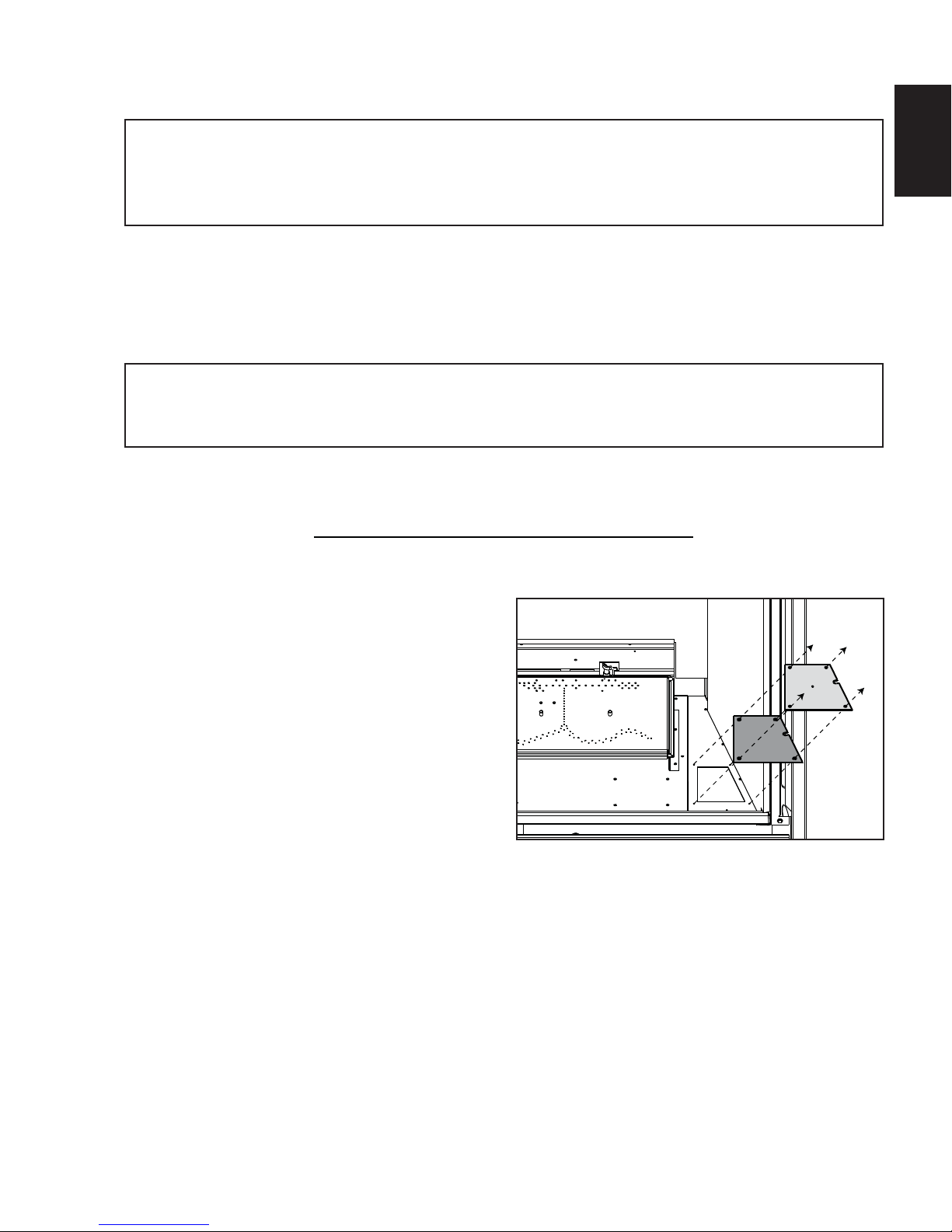
4.5 ACCESS PANEL FOR GAS LINE CONNECTION
EN
29.1A
A. Unscrew the 4 screws that hold the Access
Panel to the fi rebox.
B. Remove the Gasket (careful not to tear).
Access
Panel
Gasket
W415-1347 / A / 03.19.15
Page 26
26
4.6 GAS INSTALLATION
EN
!
WARNING
RISK OF FIRE, EXPLOSION OR ASPHYXIATION. ENSURE THERE ARE NO IGNITION SOURCES SUCH AS
SUPPORT GAS CONTROL WHEN ATTACHING GAS SUPPLY PIPE TO PREVENT DAMAGING GAS LINE.
ALWAYS LIGHT THE PILOT WHETHER FOR THE FIRST TIME OR IF THE GAS SUPPLY HAS RUN OUT
WITH THE GLASS DOOR OPENED OR REMOVED. PURGING OF THE GAS SUPPLY LINE SHOULD BE
PERFORMED BY A QUALIFIED SERVICE TECHNICIAN. ASSURE THAT A CONTINUOUS GAS FLOW IS AT
THE BURNER BEFORE CLOSING THE DOOR. ENSURE ADEQUATE VENTILATION. FOR GAS AND
ELECTRICAL LOCATIONS, SEE “DIMENSION” SECTION.
ALL GAS CONNECTIONS MUST BE CONTAINED WITHIN THE APPLIANCE WHEN COMPLETE.
HIGH PRESSURE WILL DAMAGE VALVE. DISCONNECT GAS SUPPLY PIPING BEFORE TESTING GAS
LINE AT TEST PRESSURES ABOVE 1/2 PSIG.
VALVE SETTINGS HAVE BEEN FACTORY SET, DO NOT CHANGE.
Installation and servicing to be done by a qualifi ed installer. Do not use open fl ame.
• Move the appliance into position and secure.
• If equipped with a fl ex connector the appliance is designed to accept a 1/2” (13mm) gas supply.
Without the connector it is designed to accept a 3/8” (9.5mm) gas supply. The appliance is equipped
with a manual shut off valve to turn off the gas supply to the appliance.
• Connect the gas supply in accordance to local codes. In the absence of local codes, install to the
current CAN/CSA-B149.1 Installation Code in Canada or to the current National Fuel Gas Code, ANSI
Z223.1 / NFPA 54 in the United States.
• When fl exing any gas line, support the gas valve so that the lines are not bent or kinked.
• Check for gas leaks by brushing on a soap and water solution.
SPARKS OR OPEN FLAMES.
30.1A
W415-1347 / A / 03.19.15-
Page 27
5.0 FRAMING
27
!
WARNING
RISK OF FIRE!
IN ORDER TO AVOID THE POSSIBILITY OF EXPOSED INSULATION OR VAPOUR BARRIER COMING
IN CONTACT WITH THE APPLIANCE BODY, IT IS RECOMMENDED THAT THE WALLS OF THE
APPLIANCE ENCLOSURE BE “FINISHED” (IE: DRYWALL / SHEETROCK), AS YOU WOULD FINISH
ANY OTHER OUTSIDE WALL OF A HOME. THIS WILL ENSURE THAT CLEARANCE TO
COMBUSTIBLES IS MAINTAINED WITHIN THE CAVITY.
DO NOT NOTCH THE FRAMING AROUND THE APPLIANCE STAND-OFFS. FAILURE TO MAINTAIN
AIR SPACE CLEARANCE MAY CAUSE OVER HEATING AND FIRE. PREVENT CONTACT WITH
SAGGING OR LOOSE INSULATION OR FRAMING AND OTHER COMBUSTIBLE MATERIALS. BLOCK
OPENING INTO THE CHASE TO PREVENT ENTRY OF BLOWN-IN INSULATION. MAKE SURE
INSULATION AND OTHER MATERIALS ARE SECURED.
WHEN CONSTRUCTING THE ENCLOSURE ALLOW FOR FINISHING MATERIAL THICKNESS TO
MAINTAIN CLEARANCES. FRAMING OR FINISHING MATERIAL CLOSER THAN THE MINIMUMS
LISTED MUST BE CONSTRUCTED ENTIRELY OF NON-COMBUSTIBLE MATERIALS. MATERIALS
CONSISTING ENTIRELY OF STEEL, IRON, BRICK, TILE, CONCRETE, SLATE, GLASS OR PLASTERS,
OR ANY COMBINATION THEREOF ARE SUITABLE. MATERIALS THAT ARE REPORTED AS PASSING
ASTM E 136, STANDARD TEST METHOD FOR BEHAVIOUR OF MATERIALS IN A VERTICAL TUBE
FURNACE AT 1382° F (750°C) AND UL763 SHALL BE CONSIDERED NON-COMBUSTIBLE
MATERIALS.
MINIMUM CLEARANCE TO COMBUSTIBLES MUST BE MAINTAINED OR A SERIOUS FIRE HAZARD
COULD RESULT.
THE APPLIANCE REQUIRES A MINIMUM ENCLOSURE HEIGHT. MEASURE FROM THE APPLIANCE
BASE.
IF STEEL STUD FRAMING KITS WITH CEMENT BOARD ARE PROVIDED, OR SPECIFIED IN THE
INSTALLATION INSTRUCTIONS. THEY MUST BE INSTALLED.
FINISHING MUST BE DONE USING A NON-COMBUSTIBLE MATERIAL EXTENDING FROM THE TOP
OF THE APPLIANCE SUCH AS NON-COMBUSTIBLE BOARD, CERAMIC TILE, MARBLE, ETC. DO
NOT USE WOOD OR DRYWALL.
ANY FIRE RATED DRYWALL IS NOT ACCEPTABLE.
71.1B
It is best to frame your appliance after it is positioned and the vent system is installed. Frame to local building codes.
EN
It is not necessary to install a hearth extension with this appliance.
When roughing in the appliance, raise the appliance to accommodate for the thickness of the fi nished fl oor materials,
i.e. tile, carpeting, hard wood, which if not planned for will interfere with the opening of the lower access door and the
installation of many decorative fl ashing accessories.
Combustible materials may be installed fl ush with the front of the appliance but must not cover any of the black face-
areas of the appliance. Non-combustible material (brick, stone or ceramic tile) may protrude in these areas.
W415-1347 / A / 03.19.15
Page 28

EN
DO NOT BUILD INTO THIS AREA - IT MUST BE LEFT
CLEAR TO PROVIDE ADEQUATE CLEARANCE FOR
THE VENT IN THIS 14” (356MM) WIDE AREA CENTERED
ALONG THE FRONT OF THE APPLIANCE. NO
COMBUSTIBLES ARE ALLOWED.
!
WARNING
70”
1778mm **
3 1/2”
89mm MAX
14”
356mm MIN
1 1/2”
38mm MAX
20 1/4”
514mm **
41 1/4”
1048mm **
A
NOTE: THREE BRACES ARE REQUIRED (AS
NAILERS).
4 3/4”
121mm
6 1/2”
165mm
28
* Allow for fi nished fl oor and hearth thickness when setting these dimensions.
** When constructing the enclosure allow for fi nishing material thickness to maintain clearances.
FRAMING DIMENSIONS
Ref HD35 HD40 HD46
A 35 3/4” (908mm) 40 3/4” (1035mm) 46 3/4” (1187mm)
W415-1347 / A / 03.19.15-
Page 29

5.1 MINIMUM CLEARANCE TO COMBUSTIBLES
COMBUSTIBLE FRAMING:
Sides, back, bottom and top
of the appliance
COMBUSTIBLE FINISHING:
Sides, Bottom and Top 0" to front edge of the appliance
Enclosure Top 70" (1778mm) from the bottom of the appliance
Recessed Depth 20" (508mm)
Sides and bottom of the vent
pipe
Top of vent pipe 2"* (51mm)
Ceiling 62" (1575mm) from the bottom of the appliance
* HORIZONTAL VENT SECTIONS: A minimum clearance of 1" (25mm) at the bottom and sides and 2"
(51mm) at the top of the vent pipe in all horizontal runs to combustibles is required except for clearances in
appliance enclosures. Horizontal vent sections within enclosures require a minimum clearance of 9” (229mm)
at the top of the vent pipe. See “MINIMUM CLEARANCE TO COMBUSTIBLE ENCLOSURES” section. Use
fi restop spacer W010-1777 (supplied) where vent pipe penetrates combustible walls.
* VERTICAL VENT SECTIONS: A minimum clearance of 1" (25mm) all around the vent pipe on all vertical
runs to combustibles is required except for clearances in appliance enclosures. Vertical vent sections
within enclosures require a minimum clearance of 4" (102mm) to the sides of the vent pipe. See “MINIMUM
CLEARANCE TO COMBUSTIBLE ENCLOSURES” section. Use fi restop spacer W500-0367 (not supplied)
where vent pipe penetrates combustible ceilings or fl oors.
0" to stand-offs
1"* (25mm)
29
EN
D
OUTSIDE
INSIDE
CHASE
102mm
F
2"
4"
152mm
6"
51mm
102mm
C
A
BACK WALL OF CHASE / ENCLOSURE
(INCLUDING ANY FINSIHING MATERIALS)
B
CHASE
F
A
A
51mm
2"
4"
MINIMUM ENCLOSURE CLEARANCES
Ref HD35 HD40 HD46
A 35 3/4" (908mm) 40 3/4" (1035mm) 46 3/4" (1187mm)
B 61 1/2" (1562mm) 66 1/2" (1689mm) 72 1/2" (1842mm)
C 43
D 14
1/2" (1105mm) 47" (1194mm) 51 1/4" (1302mm)
13/16" (376mm) 16 9/16" (421mm) 18 11/16" (475mm)
E 30 3/4" (781mm) 33 1/4" (845mm) 36 1/4" (921mm)
F 20 1/4" (514mm) 20 1/4" (514mm) 20 1/4" (514mm)
E
W415-1347 / A / 03.19.15
Page 30
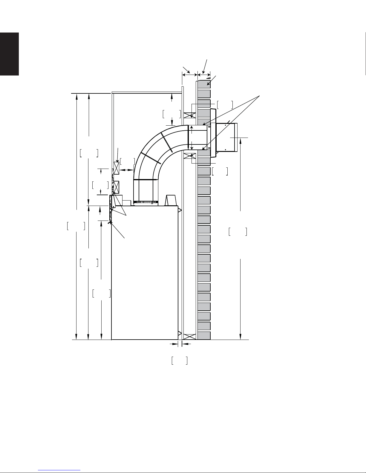
30
5.2 MINIMUM CLEARANCE TO COMBUSTIBLE ENCLOSURES
EN
32”
813mm
70”
1778mm
38”
965mm
6 1/2”
165mm
COMBUSTIBLE
9”
229mm
WOOD
HEADER
4”
102mm
NON-COMBUSTIBLE
MATERIAL
FRONT HOOD
NON-COMBUSTIBLE
BRICK
2”
51mm
1”
25mm
57 1/2”
1461mm
MINIMUM
PLUS RISE
0” IF NON-COMBUSTIBLE
FINISHING IS USED
SUCH AS BRICK AND
STONE.
33 3/4”
857mm
1”
25mm
For temperature requirements, the enclosure space around and above the appliance must be left unobstructed.
It is recommended that the enclosure be ventilated at the top and bottom to circulate the hot air.
* See “VENTING” section.
W415-1347 / A / 03.19.15-
Page 31

COMBUSTIBLE
MATERIAL
NOTE: THREE BRACES
ARE REQUIRED.
NON-COMBUSTIBLE
(SUPPLIED)
6 1/2”
[165mm
MIN
B
C
A
1 1/4”
32mm
MIN
7 3/8”
187mm
MIN
B
A
NON-COMBUSTIBLE
MATERIAL SUCH AS TILE,
MARBLE GRANITE, ETC.
COMBUSTIBLE
MATERIAL
5.3 INSTALLING NON-COMBUSTIBLE BOARD
NON-COMBUSTIBLE FINISHING MATERIAL COMBUSTIBLE FINISHING MATERIAL
31
EN
NOTE: For detailed installation instructions on the 4-sided frame, optional faceplate or bevelled trims
refer to the installation instructions provided with the kit.
A joint compound that is resistant to heat and cracking should be used when taping and mudding
seams.
NON- COMBUSTIBLE MATERIAL
FINISHING DIMENSIONS
Ref HD35 HD40 HD46
A 33"
(838mm)
B 33
(857mm)
(965mm)
3/4"
33 3/4"
(857mm)
38"
44"
(1117mm)
33 3/4"
(857mm)
COMBUSTIBLE MATERIAL
FINISHING DIMENSIONS
Ref HD35 HD40 HD46
A 35 3/4"
(908mm)
B 35 1/2"
(902mm)
40 3/4"
(1035mm)
40 1/4"
(1022mm)
Non-combustible Material Defi nitions
C 41"
(1041mm)
41”
(1041mm)
46 3/4"
(1187mm)
46 1/4"
(1175mm)
41"
(1041mm)
Material which will not ignite and burn. Materials consisting entirely of steel, iron, brick, tile, concrete, slate,
glass or plasters, or any combination thereof are suitable.
Materials that are reported as passing ASTM E 136, Standard Test Method for Behaviour of Materials in a
Vertical Tube Furnace at 750°C and UL763 shall be considered non-combustible materials.
W415-1347 / A / 03.19.15
Page 32

EN
32
6” (152mm)
4” (102mm)
2” (51mm)
0” (0mm)
4”
(102mm)
3” (76mm)
2” (51mm)
TOP OF
APPLIANCE
SAFETY
SCREEN
WARNING: 2" (51mm) clearance from the surround is required for any additional projecting out a
maximum 2" (51mm). if greater projections are desired, increase the clearance from the surround by 2"
(51mm) for every 1" (25mm) of additional projection.
DOOR
5.4 ALCOVE INSTALLATION
RECESS OR
ALCOVE
AREA
NOTE: Recesses or alcoves above the appliance can be made as deep as desired provided the minimum
clearances to combustibles are maintained.
Non-combustible material can be used, provided the minimum clearances to combustible materials are applied.
The minimum enclosure volume must be increased by no less than the volume of the recess. This adjustment
can be made by increasing any or all of the height, width and depth of the enclosure.
W415-1347 / A / 03.19.15-
ENCLOSURE
AREA
APPLIANCE
71.2
Page 33

5.5 MINIMUM MANTEL CLEARANCES
!
WARNING
RISK OF FIRE, MAINTAIN ALL SPECIFIED AIR SPACE CLEARANCES TO COMBUSTIBLES. FAILURE
TO COMPLY WITH THESE INSTRUCTIONS MAY CAUSE A FIRE OR CAUSE THE APPLIANCE TO
OVERHEAT. ENSURE ALL CLEARANCES (I.E. BACK, SIDE, TOP, VENT, MANTEL, FRONT, ETC.) ARE
CLEARLY MAINTAINED.
WHEN USING PAINT OR LACQUER TO FINISH THE MANTEL, THE PAINT OR LACQUER MUST BE
HEAT RESISTANT TO PREVENT DISCOLOURATION.
73.1
Combustible mantel clearance can vary according to the mantel depth. Use the graph to help evaluate the
clearance needed.
MANTEL DIMENSIONS
Ref Height Depth
A 38" (965mm)
B 13" (330mm) 2" (51mm)
C 15" (381mm) 4" (102mm)
D 17" (432mm) 6" (152mm)
E 19" (483mm) 8" (203mm)
E
D
C
B
33
EN
21
0
+
19
$
(
17
1
,
7
*
15
(
+
13
/
7
11
246810
MANTEL DEPTH
5.6 NON-COMBUSTIBLE FACING MATERIAL
FINISH
MATERIAL
NON-COMBUSTIBLE
FACING MATERIAL
FRONT OF
APPLIANCE
3/4” (19mm)
A
TOP VIEWSIDE VIEW
FINISH
MATERIAL
3/4” (19mm)
FRONT OF
APPLIANCE
WARNING: Non-combustible facing material must not protrude more than 3/4” (19mm) from the top,
and/or sides of the appliance. If it does, it is considered a non-combustible mantel and must meet the
non-combustible mantel clearance requirements.
NON-COMBUSTIBLE
FACING MATERIAL
71.3A
W415-1347 / A / 03.19.15
Page 34

34
6.0 FINISHING
EN
NEVER OBSTRUCT THE FRONT OPENING OF THE APPLIANCE.
THE FRONT OF THE APPLIANCE MUST BE FINISHED WITH ANY NON-COMBUSTIBLE MATERIALS
SUCH AS BRICK, MARBLE, GRANITE, ETC., PROVIDED THAT THESE MATERIALS DO NOT GO
BELOW THE SPECIFIED DIMENSION AS ILLUSTRATED.
DO NOT STRIKE, SLAM OR SCRATCH GLASS. DO NOT OPERATE APPLIANCE WITH GLASS
REMOVED, CRACKED, BROKEN OR SCRATCHED.
FACING AND/OR FINISHING MATERIAL MUST NEVER OVERHANG INTO THE APPLIANCE OPENING.
!
WARNING
RISK OF FIRE!
6.1 SAFETY SCREEN REMOVAL / INSTALLATION
!
WARNING
GLASS MAY BE HOT, DO NOT TOUCH GLASS UNTIL COOLED.
THE DOOR LATCHES ARE PART OF A SAFETY RELIEF SYSTEM AND MUST BE PROPERLY
ENGAGED. DO NOT OPERATE THE APPLIANCE WITH LATCHES DISENGAGED.
FACING AND/OR FINISHING MATERIALS MUST NOT INTERFERE WITH AIR FLOW THROUGH AIR
OPENINGS, LOUVRES OPENINGS, OPERATION OF LOUVRES OR DOORS OR ACCESS FOR
SERVICE. OBSERVE ALL CLEARANCES WHEN APPLYING COMBUSTIBLE MATERIALS.
BEFORE DOOR IS REMOVED TURN THE APPLIANCE OFF AND WAIT UNTIL APPLIANCE IS COOL TO
THE TOUCH. DOORS ARE HEAVY AND FRAGILE SO HANDLE WITH CARE.
A barrier designed to reduce the risk of burns from the hot viewing glass is provided with the appliance
and must be installed. Before the glass door can be removed, the surround with safety screen must be
removed. Lift the surround with safety screen off the 4 shoulder screws, tilt the top forward and remove from
the appliance.
72.1A
75.1
SAFETY SCREEN
Reverse these steps to re-install the safety screen and door. Ensure safety screen is installed correctly.
W415-1347 / A / 03.19.15-
SAF
ETY SCREEN
Page 35

6.3 FRONT SURROUND INSTALLATION
Secure the front surround brackets using 6 screws. Ensure to drill the brackets into the wall studs, see Figure 1.
NOTE: The 39" (991mm) is measured between the bottom of the appliance and the center of the middle
hole of the mounting bracket.
Install the front surround. Lift the surround up and slide onto the brackets until secure, see Figure 2.
Secure the bottom of the surround with 2 screws, see Figure 3.
FIG. 1
“A”
39” (991mm)
35
EN
FIG. 2
6.2 GLASS DOOR REMOVAL / INSTALLATION
Before the glass door can be removed, the surround
with safety screen must be removed, see “SAFETY
SCREEN REMOVAL / INSTALLATION” section.
The glass door is secured to the top front edge of the
appliance with two latches. Pull the handles of the
latches forward, then lift the latches out from the door
frame to release the top of the door. Next, pivot the
door forward until the top edge clears the front of the
appliance. Carefully grip the sides of the door lifting it
out from the retainer along the bottom of the door.
NOTE: These latches make up the spring relief
system for the appliance. Ensure they open freely
and close sealed.
FIG. 3
HANDLES
Reverse these instructions to reinstall the door and
surround with safety screen. Ensure the surround with
safety screen is installed correctly.
W415-1347 / A / 03.19.15
Page 36

36
6.4 LOG PLACEMENT
EN
!
WARNING
FAILURE TO POSITION THE LOGS IN ACCORDANCE WITH THESE DIAGRAMS OR FAILURE TO USE
ONLY LOGS SPECIFICALLY APPROVED WITH THIS APPLIANCE MAY RESULT IN PROPERTY
DAMAGE OR PERSONAL INJURY.
LOGS MUST BE PLACED IN THEIR EXACT LOCATION IN THE APPLIANCE. DO NOT MODIFY THE
PROPER LOG POSITIONS, SINCE APPLIANCE MAY NOT FUNCTION PROPERLY AND DELAYED
IGNITION MAY OCCUR.
THE LOGS ARE FRAGILE AND SHOULD BE HANDLED WITH CARE.
76.1A
The individual logs can be easily identifi ed by the numbers cast on the underside of each log.
Phazer
that is different in every installation. Take the time to carefully position the glowing embers for a maximum
glowing effect. During the initial use of the appliance, log colours may vary. During the initial use of the appliance the colours will become more uniform as colour pigments burn in during the heat activated curing process.
TM
logs and glowing embers exclusive to Wolf Steel Ltd., provide a unique and realistic glowing effect
LOG IDENTIFICATION CHART
LOGS HD35 HD40 HD46
Rear Log W135-0339 W135-0339 W135-0339
Middle Log W135-0409 W135-0409 W135-0409
Left Log W135-0406 W135-0406 W135-0406
Right Log W135-0407 W135-0407 W135-0407
Charcoal Strip Log W135-0408 W135-0408 W135-0408
Base Left Log N/A N/A W135-0392
Base Right Log N/A N/A W135-0393
A. Place the rear log (W135-0339) on rear bracket, ensure the log is
seated properly on the rear bracket and located on the center pin.
B. Place the middle log (W135-0409) on top of the burner pan. Use
the two bottom holes of the log to locate it onto the two pins on the
burner pan.
C. HD35/40: Place the log charcoal strip (W135-0408) on top of
the front grate by engaging the two cut out notches onto the two
middle posts of the front grate.
HD46: Place the log charcoal strip (W135-0408) on top of the sup-
port ember strip.
W415-1347 / A / 03.19.15-
Page 37

D. Place the right log (W135-0407) on top of the middle log by locat-
ing the bottom rectangular holes of the right log onto the knob of
the middle log. The end of the log with a cut out notch will seat
against the back of the right end front grate post.
E. Place the left log (W135-0406) using the bottom rectangular hole to
position onto the knob of the middle log located on the left. The notch
on the bottom end of the log is to seat onto the left end front grate
post.
F. HD46 ONLY: Place the base right log (W135-0393)
using the bottom rectangular hole to engage with
the two pins on the right as illustrated.
37
EN
G. HD46 ONLY: Place the base left log (W135-
0392) using the bottom hole of the log to
locate it onto the base support bracket pin on
the left side.
W415-1347 / A / 03.19.15
Page 38

38
#4 GLOWING EMBERS
6.5 GLOWING EMBER PLACEMENT
Tear the embers into pieces and place on top of the front burner area be-
EN
6.6 CHARCOAL EMBERS
6.7 OPTIONAL VERMICULITE
6.10 LAVA ROCK
tween the middle log and charcoal strip. Care should be taken to shred the
embers into thin, small irregular pieces as only the exposed edges of the
fi bre hairs will glow. The ember material will only glow when exposed
to direct fl ame; however, care should be taken to not block the burner
ports.
Blocked burner ports can cause an incorrect fl ame pattern, carbon deposits
and delayed ignition. PHAZER
Use only certifi ed "glowing embers" and PHAZERTM logs available from
your Authorized dealer.
Randomly place the charcoal embers along the front and sides of the log support tray in a realistic manner.
Fine dust found in the bottom of the bag should not be used.
NOTE: Charcoal embers are not to be placed on the burner.
Sprinkle vermiculite around the charcoal embers.
NOTE: Vermiculite is not to be placed on the burner.
TM
logs glow when exposed to direct fl ame.
#4 GLOWING EMBERS
32.1
33.1
Lava rock should be spread out evenly around the burner on the fi rebox base.
NOTE: Lava rock is not to be placed on the burner.
6.8 OPTIONAL CHARCOAL LUMPS (STANDARD ON HD46)
!
WARNING
CHARCOAL EMBERS, VERMICULITE AND CHARCOAL LUMPS ARE NOT TO BE PLACED ON THE
BURNER.
Place the lumps in front of the logs in a realistic manner taking care not to block any of the burner ports.
6.9 LOGO PLACEMENT
Remove the backing of the logo supplied and place on the glass viewing door or bottom access panel as
illustrated.
13mm
1/2”
LOGO
13mm
1/2”
34.1
W415-1347 / A / 03.19.15-
Page 39

7.0 OPTIONAL BLOWER INSTALLATION
39
!
WARNING
RISK OF FIRE AND ELECTRICAL SHOCK.
TURN OFF THE GAS AND ELECTRICAL POWER BEFORE SERVICING THIS APPLIANCE.
USE ONLY WOLF STEEL APPROVED OPTIONAL ACCESSORIES AND REPLACEMENT PARTS WITH
THIS APPLIANCE. USING NON-LISTED ACCESSORIES (BLOWERS, DOORS, LOUVRES, TRIMS, GAS
COMPONENTS, VENTING COMPONENTS, ETC.) COULD RESULT IN A SAFETY HAZARD AND WILL
VOID THE WARRANTY AND CERTIFICATION.
ENSURE THAT THE FAN’S POWER CORD IS NOT IN CONTACT WITH ANY SURFACE OF THE
APPLIANCE TO PREVENT ELECTRICAL SHOCK OR FIRE DAMAGE. DO NOT RUN THE POWER
CORD BENEATH THE APPLIANCE.
THE WIRE HARNESS PROVIDED IN THE BLOWER KIT IS A UNIVERSAL HARNESS. WHEN
INSTALLED, ENSURE THAT ANY EXCESS WIRE IS CONTAINED, PREVENTING IT FROM MAKING
CONTACT WITH MOVING OR HOT OBJECTS.
51.5
7.1 ACCESSING THE BLOWER
!
WARNING
BE CAREFUL NOT TO TEAR THE BURNER TRAIN GASKET. A REPLACEMENT GASKET CAN BE
ORDERED FROM YOUR LOCAL AUTHORIZED DEALER / DISTRIBUTOR.
NOTE: If optional brick panels have
been installed, they will need to be
removed prior to proceeding.
A. Remove the control access
panel.
B. Remove the door, see the
section “DOOR REMOVAL /
INSTALLATION”.
C. Carefully remove the log set
and optional brick panels if
installed, see section “LOG
PLACEMENT”.
D. Remove the 2 screws holding
the front grate in place.
E. Remove the 2 screws holding
the rear log support.
F. Remove the 9 perimeter screws as illustrated and lift out the burner base assembly and gasket. (The
gas line fl ex-connector should provide suffi cient movement to permit shifting the burner assembly on
it’s side).
FRONT
GRATE
CONTROL ACCESS PANEL
REAR LOG
SUPPORT
PERIMETER SCREWS
EN
W415-1347 / A / 03.19.15
Page 40

40
7.2 INSTALLING THE BLOWER
A. Open the blower kit and
EN
B. Reverse procedure to
remove the thermal disc from
the bracket. Remove the
speed control bracket from
the burner base assembly,
install the thermal disc and
speed control switch onto the
speed control bracket and
reattach to the burner base.
re-assemble.
GASKET
SPEED CONTROL
BRACKET
BLOWER
THERMAL
DISC
SPEED
CONTROL
SWITCH
VARIABLE
SPEED
KNOB
INSTALLATION TO BE DONE BY A QUALIFIED INSTALLER and must
be electrically connected and grounded in accordance with local codes.
In the absence of local codes, use the current CSA C22.1 Canadian
black
BLOWER
red
electrical code in Canada or the ANSI / NFPA 70 national electrical code
in the United States.
Drywall dust will penetrate into the blower bearings, causing irreparable
damage. Care must be taken to prevent drywall dust from coming into
contact with the blower or its compartment. Any damage resulting from
this condition is not covered by the warranty policy. To safely install the fan,
turn off the electricity first.
Slide the vibration reducing pad (A) into the clip (C) and up against the
THERMAL
SWITCH
white
VARIABLE
SPEED
SWITCH
threaded stud (B) at the other end. The blower must be
able to be positioned entirely onto the pad.
B
Attach the connectors from the black and white wires
to the thermal disc.
Attach the connectors from the black and red wires
to the blower.
A
C
Plug the harness cord into the receptacle.
Because the blower is thermally activated, when turned on, it will automatically start approximately 10 minutes
after lighting the fireplace and will run for approximately 30-45 minutes after the fireplace has been turned off.
Use of the fan increases the output of heat.
51.2
W415-1347 / A / 03.19.15-
Page 41

8.0 WIRING DIAGRAM / ELECTRICAL INFORMATION
41
!
WARNING
DO NOT USE THIS APPLIANCE IF ANY PART HAS BEEN UNDER WATER. CALL A QUALIFIED
SERVICE TECHNICIAN IMMEDIATELY TO HAVE THE APPLIANCE INSPECTED FOR DAMAGE TO THE
ELECTRICAL CIRCUIT.
RISK OF ELECTRICAL SHOCK OR EXPLOSION. DO NOT WIRE 110V TO THE VALVE OR TO THE
APPLIANCE WALL SWITCH. INCORRECT WIRING WILL DAMAGE CONTROLS.
ALL WIRING SHOULD BE DONE BY A QUALIFIED ELECTRICIAN AND SHALL BE IN COMPLIANCE
WITH LOCAL CODES. IN THE ABSENCE OF LOCAL CODES, USE THE CURRENT CSA22.1 CANADIAN
ELECTRIC CODE IN CANADA OR THE CURRENT NATIONAL ELECTRIC CODE ANSI/NFPA NO. 70 IN
THE UNITED STATES.
ALWAYS LIGHT THE PILOT WHETHER FOR THE FIRST TIME OR IF THE GAS SUPPLY HAS RAN OUT,
WITH THE GLASS DOOR OPENED OR REMOVED.
69.2
8.1 WIRING REQUIREMENTS
A. This appliance must be electrically connected and grounded in accordance with local codes. In the
absence of local codes, use the current CSA C22.1 CANADIAN ELECTRICAL CODE in Canada or the
ANSI/NFPA 70-1996 NATIONAL ELECTRICAL CODE in the United States.
B. Low voltage and 110 VAC voltage cannot be shared within the same wall box.
C. Wire the appliance junction box to 110 VAC for proper operation of the appliance.
D. Refer to “WIRING DIAGRAM” section.
E. This appliance is equipped with an electronic control valve which operates on a 3 volt system.
F. Plug the 3 volt AC transformer into the appliance junction box to supply power to the appliance
and install two “D” cell batteries (not included) into the battery tray before use (only required if the
appliance is to operate during a power failure).
8.2 OPTIONAL ACCESSORIES REQUIREMENTS
EN
A. This appliance may be used with a wall switch and/or a remote control
B. Wiring for optional Wolf Steel approved accessories should be done now to avoid reconstruction.
Follow instructions that come with those accessories.
C. The Battery Tray, IPI Control Module, and Remote Control Receiver can be accessed through the air
space between the fi rebox front and the lower-front fi nishing cover panel.
D. The Battery Tray, IPI Control Module, Remote Control Receiver must be secured using Velcro to the
inside of the lower cover panel.
OPTIONAL REMOTE CONTROL RECEIVER
LOCATION
E. Optional remote control receiver
locations as shown in illustration
below.
JUNCTION
BOX
BATTERY
TRAY
BATTERY
RELAY
IPI MODULE
GAS VALVE
REMOTE CONTROL
RECEIVER LOCATIONS
W415-1347 / A / 03.19.15
Page 42

42
8.3 JUNCTION BOX INSTALLATION
A. Remove the two screws that secure the junction box assembly to the outer
EN
B. Remove the one screw that secures the junction box to the junction box plate
C. Route the supply wire through the 7/8” (22mm) hole of the junction box plate
D. Connect the 120 volt supply wire to the receptacle as per the CSA C22.1
E. Once the wiring is complete, re-install the junction box to
F. Re-install the junction box assembly by reversing step A
NOTE: If the appliance is already installed inside the enclosure, you can access the junction box from
inside the appliance by removing the burner base assembly, see “ACCESSING THE BLOWER” section.
shell on the left side of the fi re place and remove the junction box assembly.
and slide off the clip.
with a box connector (not supplied).
Canadian Electrical Code in Canada or the ANSI/NFPA 701996 National Electrical Code in the United States.
the junction box plate and re-secure the screw that was
removed in step B.
making sure all plugs are secure in the junction box.
1
B
2
B
A
W415-1347 / A / 03.19.15-
Page 43

8.4 WIRING DIAGRAM
!
WARNING
DO NOT WIRE 100 VOLTS TO THE VALVE OR WALL SWTICH.
A wall switch must be installed in a convenient location for the burner operation.
The recommended maximum lead length depends on the wire size:
WIRE SIZE MAX. LENGTH
14 gauge 100 feet (30m)
16 gauge 60 feet (18m)
18 gauge 40 feet (12m)
A 20’ (6m) length of wire is connected to the main burner switch leads. Connect this wire to the wall switch.
However if a greater length is required route 2-strand (solid core) wire through the electrical hole located at the
bottom left side of the appliance.
IGNITION
NOTE: WIRE TAGS
ARE BRACKETED
MODULE
YELLO [THROUGH
GAS LINE
(S)
CONDUIT]
PILOT
ASSEMBLY
43
EN
JUNCTION
BOX
NOTE: P LUG THE
3 VOLT AC ADAPTOR
INTO THE APPLIANCE
JUNCTION BOX TO
SUPPLY POWER TO
THE UNIT.
AC ADAPTOR
BATTERY
HOLDER
MAIN BURNER SWITCH
BROWN
RED
(+)
RED
BLACK
(SWI)
YELLOW
BLACK
BLACK
(-)
RED
MODULE
P
LUG
MAIN BURNER SWITCH
(20’ REMOTE SWITCH
WIRE SUPPLIED)
BATTERY
RELAY
BLACK
(TP)
ORANGE X2
(THTP)
G
REEN X2
(TH)
WIRE
HARNESS
ORANGE [THROUGH
INDEPENDENT
(I)
CONDUIT]
PILOT
G
AS LINE
GAS VALVE
ORANGE
LACK
B
GREEN
BLACK
LUE
B
RELAY
PLUG
W415-1347 / A / 03.19.15
Page 44

44
9.0 OPERATION
EN
!
WARNING
IF YOU DO NOT FOLLOW THESE INSTRUCTIONS EXACTLY, A FIRE OR EXPLOSION MAY RESULT
CAUSING PROPERTY DAMAGE, PERSONAL INJURY OR LOSS OF LIFE.
ALWAYS LIGHT THE PILOT WHETHER FOR THE FIRST TIME OR IF THE GAS SUPPLY HAS RUN OUT WITH
THE GLASS DOOR OPENED OR REMOVED.
Ensure that a continuous gas flow is at the burner before installing the door. When lit for the first time, the appliance will emit an odor for a
few hours. This is a normal temporary condition caused by the "burn-in" of paints and lubricants used in the manufacturing process and will
not occur again. After extended periods of non-operation such as following a vacation or a warm weather season, the appliance may emit a
slight odor for a few hours. This is caused by dust particles in the heat exchanger burning off. In both cases, open a window to sufficiently
ventilate the room.
FOR YOUR SAFETY READ BEFORE LIGHTING:
A. This appliance is equipped with an ignition device which automatically lights he pilot. Do not try to light by hand.
B.
Before operating smell all around the appliance area for gas and next to the floor because some gas is heavier than air and will settle on
the floor.
C. Use only your hand to turn the gas control knob. Never use tools. If the knob will not turn by hand, do not try to repair it. Call a qualified
service technician. Force or attempted repair may result in a fire or explosion.
D. Do not use this appliance if any part has been under water. Immediately call a qualified service technician to inspect the appliance and
replace any part of the control system and any gas control which has been under water.
WHAT TO DO IF YOU SMELL GAS:
ƔTurn off all gas to the appliance.
ƔOpen windows.
ƔDo not try to light any appliance.
ƔDo not touch any electric switch; do not use any phone
in your building.
ƔImmediately call your gas supplier from a neighbor's
phone. Follow the gas supplier's instructions.
ƔIf you cannot reach your gas supplier, call the fire
department.
LIGHTING INSTRUCTIONS:
1. Stop! Read the above safety information on this label.
2. Turn remote wall switch to off position.
3. Turn off all electrical power to the appliance and remove batteries.
4. This appliance is equipped with an ignition device which automatically lights the pilot. Do not try to light the pilot by hand.
5. Turn manual shutoff valve clockwise to off.
6. Open the glass door.
7. Wait five (5) minutes to clear out any gas. If you smell gas including near the floor, STOP! Follow “B” in the
above safety information on this label. If you don’t smell gas go to the next step.
8. Close the glass door.
9. Turn manual shutoff valve counter-clockwise to on.
10. Turn on all electrical power to the appliance and re-install batteries.
11. Turn on remote wall switch to on position.
12. If appliance will not operate, follow instructions “TO TURN OFF GAS” and call your
service technician or gas supplier.
Manual Shut-off
Valve Shown in
“OFF” position.
TO TURN OFF GAS
1. Turn off remote wall switch to the appliance.
2. Turn off all electrical power to the appliance if service is to be performed.
3. Turn manual shutoff valve clockwise to off. Do not force.
47.6
W415-1347 / A / 03.19.15-
Page 45

10.0 ADJUSTMENT
45
10.1 PRESSURE ADJUSTMENT
Check Pressure Readings:
Inlet pressure can be checked by turning screw (A) counter-clockwise 2 or 3
A
turns and then placing pressure gauge tubing over the test point. Gauge should
readas described on the chart below. Check with main burner operating on
“HI”.
Outlet pressure can be checked the same as above using screw (B). Gauge
should read as described on the chart below. Check with main burner
operating on “HI”.
AFTER T AKING PRESSURE READINGS, BE SURE T O TURN SCREWS CLOCKWISE FIRMLY TO RESEAL.
DO NOT OVERTORQUE.
Leak test with a soap and water solution.
Prior to pilot adjustment, ensure that the pilot
assembly has not been painted. If overspray or
Pressure
Inlet
Outlet
Natural Gas
(inches)
7"
(MIN. 4.5")
3.5"
Natural Gas
(millibars)
17.4mb
(MIN. 11.2mb)
8.7mb
Propane
(inches)
13"
(MIN. 11")
10"
(millibars)
(MIN. 27.4mb)
painting of the pilot assembly has occurred
remove the paint from the pilot assembly, or replace. Fine emery cloth or sandpaper can be used to remove
the paint from the pilot hood, electrode and fl ame sensor.
39.5B
10.2 VENTURI ADJUSTMENT
This appliance has an air shutter that has been factory set open according
to the chart below:
Regardless of venturi orientation, closing the air shutter will cause a more
yellow flame, but can lead to carboning. Opening the air shutter will cause a
more blue flame, but can cause flame lifting from the burner ports. The
flame may not appear yellow immediately; allow 15 to 30 minutes for the
final flame colour to be established.
AIR SHUTTER ADJUSTMENT MUST ONLY BE DONE BY A QUALIFIED
INSTALLER!
To access the air shutter, remove the control access panel, remove the glass door assembly and carefully remove
the log set. Remove the four screws attached to the burner pan. Slide the burner pan to the left roughly 1” (25mm)
then lift up.
Air shutters have been factory set open according to the Venturi
Adjustment Chart. These settings are for (maximum) horizontal
VENTURI ADJUSTMENT CHART
FUEL HD35 HD40 HD46
NG 1/8"
termination. Adjustment may be required depending on fuel type,
vent confi guration and altitude.
LP 3/8"
VENTURI
BURNER
ORIFICE
49.1
(3mm)
(10mm)
1/8"
(3mm)
7/16"
(11mm)
EN
B
Propane
32.4mb
24.9mb
AIR
SHUTTER
OPENING
1/8"
(3mm)
7/16"
(11mm)
W415-1347 / A / 03.19.15
Page 46

46
10.3 FLAME CHARACTERISTICS
It’s important to periodically perform a visual check of the pilot and burner
EN
fl ames. Compare them to the illustrations provided. If any fl ames appear
abnormal call a service person.
HD35 / HD40
11.0 MAINTENANCE
MAINTENANCE
MAINTENANCE
MAINTENANCE
TURN OFF THE GAS AND ELECTRICAL POWER BEFORE SERVICING THE APPLIANCE.
APPLIANCE MAY BE HOT, DO NOT SERVICE UNTIL APPLIANCE HAS COOLED.
DO NOT USE ABRASIVE CLEANERS.
DO NOT PAINT THE PILOT ASSEMBLY.
CAUTION: Label all wires prior to disconnection when servicing controls. Wiring errors can cause improper
and dangerous operation. Verify proper operation after servicing. This appliance and its venting system
should be inspected before use and at least annually by a qualifi ed service person. The appliance area must
be kept clear and free of combustible materials, gasoline or other fl ammable vapors and liquids. The fl ow of
combustion and ventilation air must not be obstructed.
A. In order to properly clean the burner and pilot assembly, remove the logs, rocks and/or glass to
expose both assemblies.
B. Keep the control compartment, media, burner, air shutter opening and the area surrounding the logs
clean by vacuuming or brushing, at least once a year.
C. Check to see that all burner ports are burning. Clean out any of the ports which may not be burning or
are not burning properly.
D. Check to see that the pilot fl ame is large enough to engulf the fl ame sensor and/or thermocouple /
thermopile as well as reaches the burner.
E. Replace the cleaned logs, rocks or glass. Failure to properly position the media may cause carboning
which can be distributed in the surrounding living area.
F. Check to see that the main burner ignites completely on all openings when turned on. A 5 to 10
second total light-up period is satisfactory. If ignition takes longer, consult your local authorized dealer /
distributor.
G. Check that the gasketing on the sides, top and bottom of the door is not broken or missing. Replace if
necessary.
H. If for any reason the vent air intake system is disassembled, re-install and re-seal per the instructions
provided for the initial installation.
I. Cleaning the safety barrier may be necessary due to excessive lint / dust from carpeting, pets, etc.
simply vacuum using the brush attachment.
J. Ensure the relief system performs effectively. Check that the gasket is not worn or damaged. Replace
if necessary.
HD46
!
WARNING
54.3
40.1D
W415-1347 / A / 03.19.15-
Page 47

11.1 ANNUAL MAINTENANCE
47
!
WARNING
THE FIREBOX BECOMES VERY HOT DURING OPERATION. LET THE APPLIANCE COOL
COMPLETELY OR WEAR HEAT RESISTANT GLOVES BEFORE CONDUCTING SERVICE.
NEVER VACUUM HOT EMBERS.
DO NOT PAINT THE PILOT ASSEMBLY.
• This appliance will require maintenance which should be planned on an annual basis.
• Service should include cleaning, battery replacement, venting inspection and inspection of the burner,
media and fi rebox. Refer to the door removal section and remove the door as instructed.
• Carefully remove media if necessary (logs, glass, brick panels etc).
• Using a vacuum with a soft brush attachment, gently remove any dirt, debris or carbon build up from the
logs, fi rebox and burner. For glass media, follow the installation instructions for pre-cleaning.
• Also gently remove any build-up on the pilot assembly including, if equipped; thermopile, thermocouple,
fl ame sensor and igniter.
Scotch-Brite™ scrubbing pad to remove any oxides.
soft brush attachment.
• Inspect all accessible gaskets and replace as required.
• Access the blower, if equipped and clean using a soft brush and vacuum.
• Re-assemble the various components in reverse order.
• Inspect the relief system. The appliance relieves through the main glass door or through the fl aps on the
fi rebox top. Ensure they open freely, and close sealed.
• Check the gas control valve pilot and Hi / Lo knobs move freely (if equipped) – replace if any stiffness in
movement is experienced.
• Check for gas leaks on all gas connections up and downstream from the gas valve including the pilot tube
connections.
NOTE: The fl ame sensor may require to be cleaned using a fi ne steel wool or
Clean the pilot assembly using a vacuum with a
It is important that the pilot assembly is not painted.
37.1C
EN
W415-1347 / A / 03.19.15
Page 48

48
GLASS
GLASS
GASKET
GLASS
RETAINER
11.2 DOOR GLASS REPLACEMENT
EN
GLASS MAY BE HOT, DO NOT TOUCH GLASS UNTIL COOLED.
CARE MUST BE TAKEN WHEN REMOVING AND DISPOSING OF ANY BROKEN DOOR GLASS OR
DAMAGED COMPONENTS. BE SURE TO VACUUM UP ANY BROKEN GLASS FROM INSIDE THE
DO NOT STRIKE, SLAM OR SCRATCH GLASS. DO NOT OPERATE APPLIANCE WITH GLASS
REMOVED, CRACKED, BROKEN OR SCRATCHED.
Only available as an assembly complete with gasket. Glass not available separately .
A. Place the door frame down careful not to scratch the paint.
B. Bend up the glass retainers being careful not to snap them.
C. Remove the glass from the frame.
NOTE: Care must be taken when removing and disposing of any broken
glass or damaged components. Be sure to vacuum
up any broken glass from inside the appliance
before operation.
D. Center the gasketed glass inside the door
frame with the thick side of the gasket facing
up.
E. Bend the glass retainers located along the
edge of the door frame over the gasket holding
the glass in place making sure that the thick
portion is protruding past the retainer. Careful not to break the glass.
!
WARNING
DO NOT USE SUBSTITUTE MATERIALS.
APPLIANCE BEFORE OPERATION.
56.2
GASKET
T
GLASS
11.3 CARE OF GLASS
DO NOT CLEAN GLASS WHEN HOT! DO NOT USE
ABRASIVE CLEANERS TO CLEAN GLASS.
Buff lightly with a clean dry soft cloth. Clean both sides
of the glass after the fi rst 10 hours of operation with a
recommended fi replace glass cleaner. Thereafter clean
as required. If the glass is not kept clean permanent
discoloration and / or blemishes may result.
This appliance is factory equipped with 4mm tempered glass. Use only replacement glass available from your
Napoleon® dealer. DO NOT SUBSTITUTE MATERIALS.
11.4 CARE OF PLATED PARTS
If the appliance is equipped with plated parts, you must clean fi ngerprints or other marks from the plated
surfaces before operating the appliance for the fi rst time. Use a glass cleaner or vinegar and towel to clean.
If not cleaned properly before operating for the fi rst time, the marks can cause permanent blemishes on
the plating. After the plating is cured, the fi ngerprints and oils will not affect the fi nish and little maintenance
is required, just wipe clean as needed. Prolonged high temperature burning with the door ajar may cause
discolouration on plated parts.
NOTE: The protective wrap on plated parts is best removed when the assembly is at room
temperature but this can be improved if the assembly is warmed, using a hair dryer or similar heat
source.
W415-1347 / A / 03.19.15-
GLASS
RETAINERS
!
WARNING
HOT GLASS WILL
CAUSE BURNS.
DO NOT TOUCH GLASS
UNTIL COOLED.
NEVER ALLOW CHILDREN
TO TOUCH GLASS.
5.1
5.5
6.1
Page 49

12.0 REPLACEMENT PARTS
49
Contact your dealer or the factory for questions concerning prices and policies on replacement parts. Normally
all parts can be ordered through your Authorized dealer / distributor.
FOR WARRANTY REPLACEMENT PARTS, A PHOTOCOPY OF THE
ORIGINAL INVOICE WILL BE REQUIRED TO HONOUR THE CLAIM.
When ordering replacement parts always give the following information:
• Model & Serial Number of appliance
• Installation date of appliance
• Part number
• Description of part
• Finish
* IDENTIFIES ITEMS WHICH ARE NOT ILLUSTRATED. FOR FURTHER INFORMATION, CONT ACT YOUR
AUTHORIZED DEALER.
FAILURE TO POSITION THE PARTS
MANUAL OR FAILURE TO USE ONLY
PARTS SPECIFICALLY APPROVED
RESULT IN PROPERTY DAMAGE OR
!
WARNING
IN ACCORDANCE WITH THIS
WITH THIS APPLIANCE MAY
PERSONAL INJURY.
41.1
EN
W415-1347 / A / 03.19.15
Page 50

EN
HD35
OVERVIEW
50
11.04.14
YES
1
16
1
17
TO: "VALVE TRAIN ASSEMBLY"
FOR REPLACEMENTS PARTS REFER
1
15
1
14
16
17
18
19
1
1
10
11
1
13
18
GL-672
W750-0273 LIGHT / FAN WIRE CONNECTOR
W185-0020 CAST GRATE
W135-0406 LEFT SIDE LOG (GL-672)
W135-0408 CHARCOAL LOG STRIP (GL-672)
W655-0454 LOG STIFFNER (GL-672)
141516
13
12
11
REF. NO. PART NUMBER DESCRIPTION
10
W361-0016 GLOWING EMBERS (GL-672)
W135-0409 MIDDLE LOG (GL-672)
W135-0407 RIGHT SIDE LOG (GL-672)
W135-0339 REAR LOG (GL-672)
18
17
YES
YES
YES
YES
15112
STOCKED STOCKED
YES
13.0 HD35 OVERVIEW
SAFETY
SCREEN
W415-1347 / A / 03.19.15-
13
ITEMS MAY NOT APPEAR EXACTLY AS ILLUSTRATED
12
1114
W010-2123 DOOR ASSEMBL Y
W565-0174 SAFETY SCREEN
W385-0334 NAPOLEON LOGO
3
2
1
REF. NO. PART NUMBER DESCRIPTION
W335-0051 HOOD
W667-0018 GASKET TAPE (X4)
W562-0060 DOOR GASKET
4
5
6
W010-2868 DOOR LATCHES (X2)
W707-0006 LIGHT TRANSFORMER (12V)
W387-001 1 LIGHT ASSEMBLY
7
8
9
Page 51

51
11.04.14
EN
14.0 HD35 VALVE TRAIN ASSEMBLY
25
25
26
26
27
27
28
28
29
29
30
30
31
31
ITEMS MAY NOT APPEAR EXACTLY AS ILLUSTRATED
REF NO. PART NUMBER DESCRIPTION STOCKED
26 W455-0071 PILOT ORIFICE (LP) YES
27 W100-0069 PILOT ASSEMBLY (NG) YES
27 W100-0093 PILOT ASSEMBLY (LP) YES
28 W750-0193 ON / OFF WIRING HARNESS
29 W350-0342 BATTERY HOUSING YES
30 W707-0002 TRANSFORMER (3V) YES
31 W725-0032 VALVE (NG)
31 W725-0049 VALVE (LP)
19
19
20
20
21
21
22
22
23
23
24
24
REF NO. PART NUMBER DESCRIPTION STOCKED
19 W456-0042 BURNER ORIFICE #42 (NG) YES
19 W456-0054 BURNER ORIFICE #54 (LP) YES
20 W010-2312 BURNER ASSEMBLY YES
21 W290-0139 VALVE TRAIN GASKET YES
22 W432-0103 FLEX MANIFOLD YES
23 W190-0022 CONTROL MODULE YES
24 W750-0250 WIRE HARNESS YES
25 W290-0140 ACCESS GASKET YES
W415-1347 / A / 03.19.15
26 W455-0049 PILOT ORIFICE (NG) YES
Page 52

EN
52
42
42
41
41
39
39
43
43
40
40
PRPH35
45
45
11.04.14
38
38
37
37
36
36
15.0 HD35 ACCESSORIES
35
35
34
34
33
33
1
1
44
44
HDF35
SAFETY
SCREEN
ITEMS MAY NOT APPEAR EXACTLY AS ILLUSTRATED
REF NO. PART NUMBER DESCRIPTION STOCKED
39 W090-0160 REAR PORCELAIN PANEL (PRPH35)
40 W090-0162 RIGHT SIDE PORCELAIN PANEL (PRPH35)
41 W090-0173 LEFT SIDE PORCELAIN PANEL (PRPHR35)
42 W090-0175 REAR PORCELAIN PANEL (PRPHR35)
43 W090-0174 RIGHT SIDE PORCELAIN PANEL (PRPHR35)
44 W010-3363 FRAME ASSEMBLY (HDF35)
45 W010-3362 TRIM ASSEMBLY (HDF35)
32
32
W415-1347 / A / 03.19.15-
GD841KT GD846KT PRPHR35
REF NO. PART NUMBER DESCRIPTION STOCKED
1 W565-0174 SAFETY SCREEN (HDF35)
32 W475-0703 LEFT SIDE BRICK PANEL (GD841KT)
33 W475-0689 REAR BRICK PANEL (GD841KT)
34 W475-0692 RIGHT SIDE BRICK PANEL (GD841KT)
35 W475-0697 LEFT SIDE MAYAN BRICK PANEL (GD846KT)
36 W475-0693 REAR MAYAN BRICK PANEL (GD846KT)
37 W475-0696 RIGHT SIDE MAYAN BRICK PANEL (GD846KT)
38 W090-0161 LEFT SIDE PORCELAIN PANEL (PRPH35)
Page 53

11 04 14
55
STOCKED
YES
YES
YES
YES
53
EN
GZ550-1KT
ITEMS MAY NOT APPEAR EXACTLY AS ILLUSTRATED
ROCK MEDIA TRAY (RAK35/40)
W135-0437 RS MULTI-COLOR ROCK CLUSTER (MKRM)
W135-0438 LS MULTI-COLOR ROCK CLUSTER (MKRM)
52
W655-0335
54
53
W135-0434 LARGE CUT OUT BROWM ROCK (MKRM)
W135-0435 LARGE CUT OUT BLACK ROCK (MKRM)
49
49
STOCKED
ROCK MEDIA TRAY (RAK46)
W655-0365
MEGK BLACK GLASS EMBERS (1lb)
MEGB BLUE GLASS EMBERS (1lb)
MEGR RED GLASS EMBERS (1lb)
MEGA AMBER GLASS EMBERS (1lb)
MEGT TOPAZ GLASS EMBERS (1lb)
W715-0629 ANDIRON (X2) (ANIH)
56
56
55
565656
57
GZ552 BLOWER (GZ550-1KT)
W361-0037 BLOWER GASKET (GZ550-1KT)
W690-0002 THERMODISC (GZ550-1KT)
KB35 VARIABLE SPEED SWITCH (GZ550-1KT)
61
60
59
58
16.0 HD35 ACCESSORIES (PAGE 2)
MKRY MKRM
14846 147 149 150 151 14846 147 149 152 153 54
156 157 158 59 60 61
W135-0428 MEDIUM GREY ROCK (MKRY/MKRM)
W135-0432 LARGE GREY ROCK (MKRY/MKRM)
W135-0424 SMALL GREY ROCK (MKRY/MKRM)
47
46
REF. NO. PART NUMBER DESCRIPTION REF. NO. PART NUMBER DESCRIPTION
484950514646464747
W135-0436 LARGE CUT OUT GREY ROCK (MKRY/MKRM)
W135-0439 RIGHT SIDE GREY ROCK CLUSTER (MKRY)
W135-0440 LEFT SIDE GREY ROCK CLUSTER (MKRY)
W135-0421 SMALL TAN ROCK (MKRM)
W135-0422 SMALL BROWN ROCK (MKRM)
W135-0423 SMALL BLACK ROCK (MKRM)
W135-0425 MEDIUM TAN ROCK (MKRM)
W135-0426 MEDIUM BROWN ROCK (MKRM)
W135-0427 MEDIUM BLACK ROCK (MKRM)
4748484849
W135-0429 LARGE TAN ROCK (MKRM)
W135-0430 LARGE BROWN ROCK (MKRM)
W135-0431 LARGE BLACK ROCK (MKRM)
W135-0433 LARGE CUT OUT TAN ROCK (MKRM)
W415-1347 / A / 03.19.15
Page 54

EN
0O
54
YES
16
17.0 HD40 OVERVIEW
1
16
1
17
TO: "VALVE TRAIN ASSEMBLY"
FOR REPLACEMENTS PARTS REFER
1
15
1
14
17
18
19
1
1
10
11
1
13
18
GL-672
15112
W185-0020 CAST GRATE
W135-0406 LEFT SIDE LOG (GL-672)
W135-0408 CHARCOAL LOG STRIP (GL-672)
W655-0454 LOG STIFFNER (GL-672)
141516
13
12
11
10 YESW750-0273 LIGHT / FAN WIRE CONNECTOR
REF. NO. PART NUMBER DESCRIPTION
STOCKED STOCKED
YES
YES
YES
W135-0409 MIDDLE LOG (GL-672)
W135-0407 RIGHT SIDE LOG (GL-672)
W135-0339 REAR LOG (GL-672)
W361-0016 GLOWING EMBERS (GL-672)
18
17
YES
YES
SAFETY
SCREEN
W415-1347 / A / 03.19.15-
13
ITEMS MAY NOT APPEAR EXACTLY AS ILLUSTRATED
12
1114
W010-1856 DOOR ASSEMBLY
W565-0176 SAFETY SCREEN
W385-0334 NAPOLEON LOGO
3
2
1
REF. NO. PART NUMBER DESCRIPTION
W335-0052 HOOD
W667-0018 GASKET T APE (X4)
W562-0060 DOOR GASKET
4
5
6
W010-2868 DOOR LATCHES (X2)
W707-0006 LIGHT TRANSFORMER (12V)
W387-001 1 LIGHT ASSEMBLY
7
8
9
Page 55

55
EN
18.0 HD40 VALVE TRAIN ASSEMBLY
25
25
26
26
27
27
28
28
29
29
30
30
31
31
ITEMS MAY NOT APPEAR EXACTLY AS ILLUSTRATED
REF NO. PART NUMBER DESCRIPTION STOCKED
26 W455-0071 PILOT ORIFICE (LP) YES
27 W100-0069 PILOT ASSEMBL Y (NG) YES
27 W100-0093 PILOT ASSEMBLY (LP) YES
28 W750-0193 ON / OFF WIRING HARNESS
29 W350-0342 BATTERY HOUSING YES
30 W707-0002 TRANSFORMER (3V) YES
31 W725-0032 VALVE (NG)
31 W725-0049 VALVE (LP)
19
19
20
20
21
21
22
22
23
23
24
24
REF NO. PART NUMBER DESCRIPTION STOCKED
19 W456-0037 BURNER ORIFICE #38 (NG) YES
19 W456-0052 BURNER ORIFICE #53 (LP) YES
20 W010-2312 BURNER ASSEMBLY YES
21 W290-0139 VALVE TRAIN GASKET YES
22 W432-0103 FLEX MANIFOLD YES
23 W190-0022 CONTROL MODULE YES
24 W750-0250 WIRE HARNESS YES
W415-1347 / A / 03.19.15
25 W290-0140 ACCESS GASKET YES
26 W455-0049 PILOT ORIFICE (NG) YES
Page 56

EN
5
0690
C
(G
)
56
42
42
41
41
39
39
43
43
40
40
PRPH40
45
45
38
38
37
37
36
36
19.0 HD40 ACCESSORIES
35
35
34
34
1
1
44
44
GD842-1KT GD845-1KT PRPHR40
HDF40
SAFETY
SCREEN
ITEMS MAY NOT APPEAR EXACTLY AS ILLUSTRATED
REF NO. PART NUMBER DESCRIPTION STOCKED
39 W090-0164 REAR PORCELAIN PANEL (PRPH40)
40 W090-0162 RIGHT SIDE PORCELAIN PANEL (PRPH40)
41 W090-0173 LEFT SIDE PORCELAIN PANEL (PRPHR40)
42 W090-0176 REAR PORCELAIN PANEL (PRPHR40)
D842-1KT
K PANEL
EAR BRI
-
W47
43 W090-0174 RIGHT SIDE PORCELAIN PANEL (PRPHR40)
44 W010-3372 FRAME ASSEMBLY (HDF40)
45 W010-3373 TRIM ASSEMBLY (HDF40)
32
32
W415-1347 / A / 03.19.15-
REF NO. PART NUMBER DESCRIPTION STOCKED
1 W565-0176 SAFETY SCREEN (HDF40)
32 W475-0703 LEFT SIDE BRICK PANEL (GD842-1KT)
33 W475-0690 REAR BRICK PANEL (GD842-1KT)
34 W475-0692 RIGHT SIDE BRICK PANEL (GD842-1KT)
35 W475-0697 LEFT SIDE MAYAN BRICK PANEL (GD845-1KT)
36 W475-0694 REAR MAYAN BRICK PANEL (GD845-1KT)
37 W475-0696 RIGHT SIDE MAYAN BRICK PANEL (GD845-1KT)
38 W090-0161 LEFT SIDE PORCELAIN PANEL (PRPH40)
Page 57

11 04 14
55
STOCKED
YES
YES
YES
YES
57
EN
20.0 HD40 ACCESSORIES (PAGE 2)
GZ550-1KT
ITEMS MAY NOT APPEAR EXACTLY AS ILLUSTRATED
ROCK MEDIA TRAY (RAK35/40)
W135-0437 RS MULTI-COLOR ROCK CLUSTER (MKRM)
W135-0438 LS MULTI-COLOR ROCK CLUSTER (MKRM)
52
W655-0335
54
53
W135-0434 LARGE CUT OUT BROWM ROCK (MKRM)
W135-0435 LARGE CUT OUT BLACK ROCK (MKRM)
49
49
STOCKED
ROCK MEDIA TRAY (RAK46)
W655-0365
MEGK BLACK GLASS EMBERS (1lb)
MEGB BLUE GLASS EMBERS (1lb)
MEGR RED GLASS EMBERS (1lb)
MEGA AMBER GLASS EMBERS (1lb)
MEGT TOPAZ GLASS EMBERS (1lb)
W715-0629 ANDIRON (X2) (ANIH)
56
56
55
565656
57
GZ552 BLOWER (GZ550-1KT)
W361-0037 BLOWER GASKET (GZ550-1KT)
W690-0002 THERMODISC (GZ550-1KT)
KB35 VARIABLE SPEED SWITCH (GZ550-1KT)
61
60
59
58
MKRY MKRM
14846 147 149 150 151 14846 147 149 152 153 54
156 157 158 59 60 61
W135-0428 MEDIUM GREY ROCK (MKRY/MKRM)
W135-0432 LARGE GREY ROCK (MKRY/MKRM)
W135-0424 SMALL GREY ROCK (MKRY/MKRM)
47
46
REF. NO. PART NUMBER DESCRIPTION REF. NO. PART NUMBER DESCRIPTION
484950514646464747
W135-0436 LARGE CUT OUT GREY ROCK (MKRY/MKRM)
W135-0439 RIGHT SIDE GREY ROCK CLUSTER (MKRY)
W135-0440 LEFT SIDE GREY ROCK CLUSTER (MKRY)
W135-0421 SMALL TAN ROCK (MKRM)
W135-0422 SMALL BROWN ROCK (MKRM)
W135-0423 SMALL BLACK ROCK (MKRM)
W135-0425 MEDIUM TAN ROCK (MKRM)
W135-0426 MEDIUM BROWN ROCK (MKRM)
W135-0427 MEDIUM BLACK ROCK (MKRM)
4748484849
W135-0429 LARGE TAN ROCK (MKRM)
W135-0430 LARGE BROWN ROCK (MKRM)
W135-0431 LARGE BLACK ROCK (MKRM)
W135-0433 LARGE CUT OUT TAN ROCK (MKRM)
W415-1347 / A / 03.19.15
Page 58

58
11 04 14
HD46
OVERVIEW
EN
YES
1
18
1
19
1
17
1
14
1
13
20
1
16
1
15
16
17
18
19
1
1
10
11
TO: "VALVE TRAIN ASSEMBLY"
FOR REPLACEMENTS PARTS REFER
GL-672 & GL-673
112
W655-0454 LOG STIFFNER (GL-672)
W185-0020 CAST GRATE
W135-0408 CHARCOAL LOG STRIP (GL-672)
13
12
11
REF. NO. PART NUMBER DESCRIPTION
W135-0339 REAR LOG (GL-672)
W135-0406 LEFT SIDE LOG (GL-672)
W135-0392 OUTER LEFT SIDE LOG (GL-673)
141516
W135-0409 MIDDLE LOG (GL-672)
W135-0393 OUTER RIGHT SIDE LOG (GL-673)
W361-0016 GLOWING EMBERS (GL-672)
W135-0407 RIGHT SIDE LOG (GL-672)
20
19
18
17
21.0 HD46 OVERVIEW
SAFETY
SCREEN
YES
YES
YES
YES
STOCKED STOCKED
15
13
YES
YES
ITEMS MAY NOT APPEAR EXACTLY AS ILLUSTRATED
12
1114
W010-1857 DOOR ASSEMBLY
W565-0175 SAFETY SCREEN
W385-0334 NAPOLEON LOGO
W335-0053 HOOD
W667-0018 GASKET T APE (X4)
W562-0060 DOOR GASKET
W010-2868 DOOR LATCHES (X2)
W707-0006 LIGHT TRANSFORMER (12V)
W387-001 1 LIGHT ASSEMBLY
W750-0273 LIGHT / FAN WIRE CONNECTOR
W415-1347 / A / 03.19.15-
3
2
1
REF. NO. PART NUMBER DESCRIPTION
4
5
6
7
10
8
9
Page 59

59
(
)
EN
22.0 HD46 VALVE TRAIN ASSEMBLY
26
26
27
27
28
28
29
29
30
30
31
31
32
32
ITEMS MAY NOT APPEAR EXACTLY AS ILLUSTRATED
REF NO. PART NUMBER DESCRIPTION STOCKED
27 W455-0071 PILOT ORIFICE (LP) YES
28 W100-0069 PILOT ASSEMBL Y (NG) YES
28 W100-0093 PILOT ASSEMBLY (LP) YES
29 W750-0193 ON / OFF WIRING HARNESS
30 W350-0342 BATTERY HOUSING YES
31 W707-0002 TRANSFORMER (3V) YES
32 W725-0032 VALVE (NG) YES
32 W725-0049 VALVE (LP) YES
YES
NG
20
20
21
21
22
22
23
23
24
24
25
25
REF NO. PART NUMBER DESCRIPTION STOCKED
20 W456-0037 BURNER ORIFICE #38 (NG) YES
20 W456-0052 BURNER ORIFICE #53 (LP) YES
21 W010-2312 BURNER ASSEMBLY YES
22 W290-0139 VALVE TRAIN GASKET YES
23 W432-0103 FLEX MANIFOLD YES
24 W190-0022 CONTROL MODULE YES
25 W750-0250 WIRE HARNESS YES
W415-1347 / A / 03.19.15
26 W290-0140 ACCESS GASKET YES
27 W455-0049 PILOT ORIFICE
Page 60

EN
1104 14
60
43
43
42
42
40
40
44
44
41
41
PRPH46
46
46
39
39
38
38
37
37
23.0 HD46 ACCESSORIES
36
36
35
35
34
34
1
1
45
45
HDF46
SAFETY
SCREEN
ITEMS MAY NOT APPEAR EXACTLY AS ILLUSTRATED
REF NO. PART NUMBER DESCRIPTION STOCKED
40 W090-0165 REAR PORCELAIN PANEL (PRPH46)
41 W090-0162 RIGHT SIDE PORCELAIN PANEL (PRPH46)
42 W090-0173 LEFT SIDE PORCELAIN PANEL (PRPHR46)
43 W090-0177 REAR PORCELAIN PANEL (PRPHR46)
44 W090-0174 RIGHT SIDE PORCELAIN PANEL (PRPHR46)
45 W010-3370 FRAME ASSEMBLY (HDF46)
46 W010-3371 TRIM ASSEMBLY (HDF46)
33
33
W415-1347 / A / 03.19.15-
GD843KT GD847KT PRPHR46
REF NO. PART NUMBER DESCRIPTION STOCKED
1 W565-0175 SAFETY SCREEN (HDF46)
33 W475-0703 LEFT SIDE BRICK PANEL (GD843KT)
34 W475-0691 REAR BRICK PANEL (GD843KT)
35 W475-0692 RIGHT SIDE BRICK PANEL (GD843KT)
36 W475-0697 LEFT SIDE MAYAN BRICK PANEL (GD847KT)
37 W475-0695 REAR MAYAN BRICK PANEL (GD847KT)
38 W475-0696 RIGHT SIDE MAYAN BRICK PANEL (GD847KT)
39 W090-0161 LEFT SIDE PORCELAIN PANEL (PRPH46)
Page 61

56
STOCKED
YES
YES
YES
YES
61
11.04.14
EN
24.0 HD46 ACCESSORIES (PAGE 2)
157 158 159 60 61 62
GZ550-1KT
ITEMS MAY NOT APPEAR EXACTLY AS ILLUSTRATED
ROCK MEDIA TRAY (RAK35/40)
W135-0437 RS MULTI-COLOR ROCK CLUSTER (MKRM)
W135-0438 LS MULTI-COLOR ROCK CLUSTER (MKRM)
53
W655-0335
55
54
W135-0434 LARGE CUT OUT BROWM ROCK (MKRM)
W135-0435 LARGE CUT OUT BLACK ROCK (MKRM)
50
50
STOCKED
ROCK MEDIA TRAY (RAK46)
MEGK BLACK GLASS EMBERS (1lb)
MEGB BLUE GLASS EMBERS (1lb)
MEGR RED GLASS EMBERS (1lb)
MEGA AMBER GLASS EMBERS (1lb)
MEGT TOPAZ GLASS EMBERS (1lb)
W655-0365
57
57
56
575757
W715-0629 ANDIRON (X2) (ANIH)
58
GZ552 BLOWER (GZ550-1KT)
W361-0037 BLOWER GASKET (GZ550-1KT)
W690-0002 THERMODISC (GZ550-1KT)
KB35 VARIABLE SPEED SWITCH (GZ550-1KT)
62
61
60
59
MKRY MKRM
14947 148 150 151 152 14947 148 150 153 154 55
W135-0428 MEDIUM GREY ROCK (MKRY/MKRM)
W135-0432 LARGE GREY ROCK (MKRY/MKRM)
W135-0424 SMALL GREY ROCK (MKRY/MKRM)
48
47
REF. NO. PART NUMBER DESCRIPTION REF. NO. PART NUMBER DESCRIPTION
495051524747474848
W135-0436 LARGE CUT OUT GREY ROCK (MKRY/MKRM)
W135-0439 RIGHT SIDE GREY ROCK CLUSTER (MKRY)
W135-0440 LEFT SIDE GREY ROCK CLUSTER (MKRY)
W135-0421 SMALL TAN ROCK (MKRM)
W135-0422 SMALL BROWN ROCK (MKRM)
W135-0423 SMALL BLACK ROCK (MKRM)
W135-0425 MEDIUM TAN ROCK (MKRM)
W135-0426 MEDIUM BROWN ROCK (MKRM)
W135-0427 MEDIUM BLACK ROCK (MKRM)
4849494950
W135-0429 LARGE TAN ROCK (MKRM)
W135-0430 LARGE BROWN ROCK (MKRM)
W135-0431 LARGE BLACK ROCK (MKRM)
W135-0433 LARGE CUT OUT TAN ROCK (MKRM)
W415-1347 / A / 03.19.15
Page 62

62
25.0 TROUBLESHOOTING
EN
!
WARNING
ALWAYS LIGHT THE PILOT WHETHER FOR THE FIRST TIME OR IF THE GAS SUPPLY HAS RUN OUT,
WITH THE GLASS DOOR OPEN OR REMOVED.
TURN OFF THE GAS AND ELECTRICAL POWER BEFORE SERVICING THE APPLIANCE.
APPLIANCE MAY BE HOT, DO NOT SERVICE UNTIL APPLIANCE HAS COOLED.
DO NOT USE ABRASIVE CLEANERS.
SYMPTOM PROBLEM TEST SOLUTION
Pilot will not
light.
Makes noise
with no
spark at pilot
burner.
Pilot sparks
but will not
light.
Carbon
is being
deposited on
glass, logs,
rocks, media
or combustion
chamber
surfaces.
Wiring. - Verify the “S” wire for the sensor and the “I” wire for the ignitor
are connected to the terminals on the module and pilot assembly.
Loose connection. - Verify no loose connections, electrical shorts in the wiring or
ground out to any metal object.
Module. - Turn the ON/OFF switch to the “OFF” position. Remove the
igniter wire “I” from the module. Place the ON/OFF switch to the
“ON” position. Hold a grounded wire about 3/16” (4.8mm) away
from the “I” terminal on the module. If no spark, the module
must be replaced. If there is a spark, the module is fi ne. Inspect
INJECTOR
PILOT TUBE
FITTING
Igniter Spark gap is
incorrect.
Transformer. - Verify the transformer is installed and plugged into the relay
A shorted or loose
Connection.
Battery backup - Check batteries.
Improper switch
wiring.
Gas supply. - Verify that the incoming gas line ball valve is “Open”. Verify that the
Out of propane gas. - Fill the tank.
Air shutter has
become blocked.
Flame is impinging
on the glass,
logs, rocks, media
or combustion
chamber.
pilot assembly for a shorted wire or cracked insulator around
the electrode.
- Spark gap of the ignitor to the pilot should be .125” (3.2mm)
box. Check voltage of the transformer under load at the spade
connections on the relay box with the ON/OFF switch in the
“ON” position. Acceptable readings of a good transformer are
between 2.8 and 3.4 volts A.C.
- Remove and reinstall the wiring harness that plugs into the module.
Remove and verify continuity of each wire in wiring harness.
- Troubleshoot the system with the simplest ON/OFF switch.
inlet pressure reading is within acceptable limits, inlet pressures
must not exceed 7” W.C. (17.4mb) for NG and 13” W.C. (32.4mb)
for LP.
- Ensure air shutter opening is free of lint or other obstructions.
- Ensure air shutter is properly set.
- Check that the glass, logs, rocks or media are correctly positioned.
- Open air shutter to increase the primary air.
- Check the input rate: check the manifold pressure and orifi ce size
as specifi ed by the rating plate.
- Check that the door gasketing is not broken or missing and that
the seal is tight.
- Check that both vent liners are free of holes and well sealed at all
joints.
- Check that minimum rise per foot has been adhered to for any
horizontal venting.
42.13C
W415-1347 / A / 03.19.15-
Page 63

SYMPTOM PROBLEM TEST SOLUTION
Continues to
spark and pilot
lights, but main
burner will not
light.
Short or loose
connection in sensor
rod.
THTP - Verify the THTP wires are connected to the valve.
- Verify all connections. Verify the connections from the pilot
assembly are tight; also verify these connections are not
grounding out to any metal.
- Verify the TH wires are connected to the valve.
63
EN
Pilot light stops
sparking / pilot
remains lit but
burner will not
turn on.
Exhaust
fumes smelled
in room,
headaches.
Flames
are very
aggressive.
Main burner
fl ame is a
blue, lazy,
transparent
fl ame.
White / grey
fi lm forms.
Poor fl ame
rectifi cation or
contaminated sensor
rod.
Wiring / connection. - Inspect all wires, ensure good tight connections. Verify that
Wiring harness. - Inspect the wiring harness and verify the harness is tightly
Module or valve. - Conduct the following test to verify if the problem is the
Appliance is spilling. - Check all seals.
Door is ajar. - Ensure door is secured properly.
Venting action is too
great.
Blockage in vent. - Remove blockage. In really cold conditions, ice buildup
Sulphur from fuel
is being deposited
on glass, logs or
combustion chamber
surfaces.
- Verify the fl ame is engulfi ng the sensor rod. This will
increase the fl ame rectifi cation. Verify correct pilot
orifi ce is installed and inlet gas specifi cations to manual.
(Remember, the fl ame carries the rectifi cation current, not
the gas. If the fl ame lifts from the pilot hood, the circuit is
broken. A wrong orifi ce or too high of an inlet pressure
can cause the pilot fl ame to lift). The sensor rod may need
cleaning.
all wiring is installed exactly as specifi ed.
connected to the module. Verify that you have all wires
connected and in the right order.
module or valve. To measure voltages, turn the multimeter
to “DC”, place the red lead from the multimeter to the screw
on the terminal block for the wire you are checking, touch
black lead to ground (valve body). Importantly, a “zero”
volts reading does not automatically indicate a bad module,
there may be too little resistance in the valve solenoid.
Check if the green wires is disconnected from the valve.
The voltage output from the module should be between 1.5
and 3 volts.
- Check to ensure venting is properly sealed or restrict vent
exit with restrictor plate. Restrictor plate not available in
some models.
may occur on the terminal and should be removed as
required. To minimize this from happening again, it is
recommended that the vent lengths that pass through
unheated spaces (attics, garages, crawl spaces) be
wrapped with an insulated mylar sleeve. Prevent sleeve
from sagging. Contact your local authorized dealer for
more information.
- Clean the glass with a recommended appliance glass
cleaner. DO NOT CLEAN GLASS WHEN HOT! If deposits
are not cleaned off regularly, the glass may become
permanently marked.
42.13_2B
W415-1347 / A / 03.19.15
Page 64

64
26.0 WARRANTY
EN
NAPOLEON® products are manufactured under the strict Standard of the world recognized ISO 9001 : 2008 Quality Assurance
Certifi cate.
NAPOLEON® products are designed with superior components and materials assembled by trained craftsmen who take great
pride in their work. The burner and valve assembly are leak and test-fi red at a quality test station. The complete appliance is
again thoroughly inspected by a qualifi ed technician before packaging to ensure that you, the customer, receives the quality
product that you expect from NAPOLEON®.
NAPOLEON® GAS APPLIANCE PRESIDENT’S LIFETIME LIMITED WARRANTY
The following materials and workmanship in your new NAPOLEON® gas appliance are warranted against defects for as long as
you own the appliance. This covers: combustion chamber, heat exchanger, stainless steel burner, phazer™ logs and embers, rocks,
ceramic glass (thermal breakage only), gold plated parts against tarnishing, porcelainized enameled components and aluminum
extrusion trims.*
Electrical (110V and millivolt) components and wearable parts such as blowers, gas valves, thermal switch, switches, wiring, remote
controls, ignitor, gasketing, and pilot assembly are covered and NAPOLEON® will provide replacement parts free of charge during
the fi rst year of the limited warranty.*
Labour related to warranty repair is covered free of charge during the fi rst year. Repair work, however, requires the prior approval of
an authorized company offi cial. Labour costs to the account of NAPOLEON® are based on a predetermined rate schedule and any
repair work must be done through an authorized NAPOLEON® dealer.
* Construction of models vary. Warranty applies only to components included with your specifi c appliance.
CONDITIONS AND LIMITATIONS
NAPOLEON® warrants its products against manufacturing defects to the original purchaser only. Registering your warranty is not necessary. Simply
provide your proof of purchase along with the model and serial number to make a warranty claim. NAPOLEON® reserves the right to have its
representative inspect any product or part thereof prior to honouring any warranty claim. Provided that the purchase was made through an authorized
NAPOLEON® dealer your appliance is subject to the following conditions and limitations:
Warranty coverage begins on the date of original installation.
This factory warranty is non-transferable and may not be extended whatsoever by any of our representatives.
The gas appliance must be installed by a licensed, authorized service technician or contractor. Installation must be done in accordance with the installation
instructions included with the product and all local and national building and fi re codes.
This limited warranty does not cover damages caused by misuse, lack of maintenance, accident, alterations, abuse or neglect and parts installed from
other manufacturers will nullify this warranty.
This limited warranty further does not cover any scratches, dents, corrosion or discoloring caused by excessive heat, abrasive and chemical cleaners nor
chipping on porcelain enamel parts, mechanical breakage of PHAZER™ logs and embers.
This warranty extends to the repair or replacement of warranted parts which are defective in material or workmanship provided that the product has been
operated in accordance with the operation instructions and under normal conditions.
After the fi rst year, with respect to this President’s Lifetime Limited Warranty, NAPOLEON® may, at its discretion, fully discharge all obligations with
respect to this warranty by refunding to the original warranted purchaser the wholesale price of any warranted but defective part(s).
NAPOLEON® will not be responsible for installation, labour or any other expenses related to the reinstallation of a warranted part and such expenses are
not covered by this warranty.
Notwithstanding any provisions contained in the President’s Lifetime Limited Warranty, NAPOLEON’S responsibility under this warranty is defi ned as
above and it shall not in any event extend to any incidental, consequential or indirect damages.
This warranty defi nes the obligations and liability of NAPOLEON® with respect to the NAPOLEON® gas appliance and any other warranties expressed or
implied with respect to this product, its components or accessories are excluded.
NAPOLEON® neither assumes, nor authorizes any third party to assume, on its behalf, any other liabilities with respect to the sale of this product.
NAPOLEON® will not be responsible for: over-fi ring, downdrafts, spillage caused by environmental conditions such as rooftops, buildings, nearby trees,
hills, mountains, inadequate vents or ventilation, excessive venting confi gurations, insuffi cient makeup air, or negative air pressures which may or may not
be caused by mechanical systems such as exhaust fans, furnaces, clothes dryers, etc.
Any damages to the appliance, combustion chamber, heat exchanger, plated trim or other components due to water, weather damage, long periods of
dampness, condensation, damaging chemicals or cleaners will not be the responsibility of NAPOLEON®.
All parts replaced under the President’s Limited Lifetime Warranty Policy are subject to a single claim.
During the fi rst 10 years NAPOLEON® will replace or repair the defective parts covered by the lifetime warranty at our discretion free of charge. From 10
years to life, NAPOLEON® will provide replacement parts at 50% of the current retail price.
All parts replaced under the warranty will be covered for a period of 90 days from the date of their installation.
The manufacturer may require that defective parts or products be returned or that digital pictures be provided to support the claim. Returned products are
to be shipped prepaid to the manufacturer for investigation. If a product is found to be defective, the manufacturer will repair or replace such defect.
Before shipping your appliance or defective components, your dealer must obtain an authorization number. Any merchandise shipped without
authorization will be refused and returned to sender.
Shipping costs are not covered under this warranty.
Additional service fees may apply if you are seeking warranty service from a dealer.
Warranty labour allowance is only for the replacement of the warranted part. Travel, diagnostic tests, shipping and other related charges are not covered
by this warranty.
ALL SPECIFICATIONS AND DESIGNS ARE SUBJECT TO CHANGE WITHOUT PRIOR NOTICE DUE TO ON-GOING PRODUCT
IMPROVEMENTS. NAPOLEON® IS A REGISTERED TRADEMARK OF WOLF STEEL LTD.
AS REQUIRED BY THE DEPARTMENT OF ENERGY IN THE UNITED STATES, 10 CFR PART 430, THE WARRANTY IS VOID IF THIS
PRODUCT IS USED WITH A THERMOSTAT. THIS APPLIES TO PRODUCT INSTALLED IN THE UNITED STATES, ONLY.
2.1C
W415-1347 / A / 03.19.15-
Page 65

27.0 SERVICE HISTORY
65
EN
43.1
W415-1347 / A / 03.19.15
Page 66

66
28.0 NOTES
EN
W415-1347 / A / 03.19.15-
44.1
Page 67

67
EN
44.1
W415-1347 / A / 03.19.15
Page 68

Products
®
Other Napoleon
'JSFQMBDF*OTFSUTt$IBSDPBM(SJMMT t(BT'JSFQMBDFTt8BUFSGBMMTt8PPE4UPWFT
)FBUJOH$PPMJOHt&MFDUSJD'JSFQMBDFTt0VUEPPS'JSFQMBDFTt(BT(SJMMT
/BQPMFPO3PBE#BSSJF0OUBSJP$BOBEB-.(
#BZWJFX%SJWF#BSSJF0OUBSJP$BOBEB-/:
.JMMFS%SJWF$SJUUFOEFO,FOUVDLZ64"
5SBOT$BOBEB)JHIXBZ.POUSFBM2VFCFD$BOBEB)5"
'JSFQMBDFT)FBUJOH$PPMJOHDBMMt(SJMMTDBMM
napoleonproducts.com
Page 69

69
INSTALLATEUR : LAISSEZ CE MANUEL AVEC L’APPAREIL.
PROPRIÉTAIRE : CONSERVEZ CE MANUEL POUR CONSULTATION ULTÉRIEURE.
NE LAISSEZ PAS LES ENFANTS OU AUTRES INDIVIDUS À RISQUE SEULS À PROXIMITÉ DE L’APPAREIL.
INSTRUCTIONS
D’INSTALLATION ET
D’OPÉRATION
CONFORME AUX LES NORMES NATIONALES AMÉRICAINES: ANSI Z21.50, CERTIFIE CANADIENNES: CSA 2.22 FOYER À GAZ VENTILÉ.
FR
CERTIFIÉ POUR LE CANADA ET LES ÉT ATS-UNIS SELON LES MÉTHODES ANSI/CSA.
CONSIGNES DE SÉCURITÉ
!
AVERTISSEMENT
Si ces instructions ne sont pas suivies à la
lettre, un incendie ou une explosion pourraient
s’ensuivre, causant des dommages matériels,
des blessures corporelles ou des pertes de vie.
- N’entreposez pas et n’utilisez pas d’essence ou autres
liquides et vapeurs infl ammables à proximité de cet ap-
pareil ou tout autre appareil.
- QUE FAIRE SI VOUS DÉTECTEZ UNE ODEUR DE GAZ :
• N’allumez aucun appareil.
• Ne touchez à aucun interrupteur électrique;
n’utilisez aucun téléphone dans votre immeuble.
• Appelez immédiatement votre fournisseur de gaz
d’un téléphone voisin. Suivez ses instructions.
• Si vous ne pouvez pas rejoindre votre fournisseur
de gaz, appelez le service des incendies.
- L’installation et l’entretien doivent être faits par un
installateur qualifi é, une agence d’entretien ou le
fournisseur.
Cet appareil peut être installé dans une maison
préfabriquée (mobile) déjà instalée à demeure si les
règlements locaux le permettent.
Cet appareil doit être utilisé uniquement avec le type de
gaz indiqué sur la plaque signalétique. Cet appareil ne
peut être converti à d’autres gaz, sauf si une trousse de
conversion est utilisée.
Produit décoratif : Ne pas utiliser comme appareil de chauffage.
APPOSEZ L’ÉTIQUETTE DU NUMÉRO DE SÉRIE DU CARTON
HD35NT, HD40NT & HD46NT
GAZ NATUREL
HD35PT, HD40PT & HD46PT
PROPANE
ÉCRAN DE PROTECTION
HDF35KSB ILLUSTRÉ
!
AVERTISSEMENT
LA VITRE CHAUDE CAUSERA
DES BRÛLURES.
NE PAS TOUCHER LA VITRE
AVANT QU’ELLE AIT REFROIDI.
NE JAMAIS LAISSER LES
ENFANTS TOUCHER LA VITRE.
Une barriére conçu à réduire le risque de brûlures
causées par le verre chaud est fourni avec l’appareil
et sera installé pour la protection des enfants et
d’autres personnes à risque.
N° de série
N° DE MODÈLE
Wolf Steel Ltd., 24 Napoleon Rd., Barrie, ON, L4M 0G8 Canada /
103 Miller Drive, Crittenden, Kentucky, USA, 41030
Téléphone 705-721-1212 • Télécopieur 705-722-6031 • www.napoleonfoyers.com • hearth@napoleonproducts.com
10,00$
ÉCRAN DE
PROTECTION
CERTIFIED
1.36E
W415-1347 / A / 03.20.15
Page 70

FR
70
TABLE DES MATIÈRES
1.0 VUE D’ENSEMBLE DE L’INSTALLATION 71
1.1 UTILISATION DE MATÉRIAUX NON COMBUSTIBLES 71
2.0 INTRODUCTION 72
2.1 DIMENSIONS 73
2.3 INSTRUCTIONS GÉNÉRALES 74
2.4 INFORMATION GÉNÉRALE 75
2.5 INFORMATION SUR LA PLAQUE D’HOMOLOGATION 76
3.0 ÉVACUATION 77
3.1 LONGUEURS DES CONDUITS D’ÉVACUATION ET COMPOSANTS 77
3.2 INSTALLATIONS TYPIQUES D’ÉVENTS 79
3.3 INSTALLATIONS PARTICULIÈRES D’ÉVENTS 80
3.3.1 ENSEMBLE PÉRISCOPIQUE 80
3.3.2 TERMINAISON EN COIN 80
3.4 EMPLACEMENTS ET DÉGAGEMENTS MINIMAUX DE LA TERMINAISON 81
3.5 SCHÉMA D’APPLICATION DES ÉVACUATIONS 82
3.6 LÉGENDE 82
3.7 VALEUR DU COUDE EN LONGUEUR D’ÉVENT 82
3.8 TERMINAISON HORIZONTALE 83
3.9 TERMINAISON VERTICALE 85
3.10 TERMINAISON VERTICALE À TRAVERS UNE CHEMINÉE EXISTANTE 87
4.0 INSTALLATION 88
4.1 PROTECTION DU MUR ET DU PLAFOND 88
4.1.1 INSTALLATION HORIZONTALE 89
4.1.2 INSTALLATION VERTICALE 89
4.2 UTILISATION DE COMPOSANTS FLEXIBLES D’ÉVACUATION 90
4.2.1 INSTALLATION DE LA TERMINAISON HORIZONTALE 90
4.2.2 INSTALLATION DE LA TERMINAISON VERTICALE 91
4.3 UTILISATION DE COMPOSANTS RIGIDES D’ÉVACUATION 92
4.3.1 INSTALLATION DE LA TERMINAISON HORIZONTALE 92
4.3.2 INSTALLATION ÉTENDUE DE LA TERMINAISON HORIZONTALE 92
4.3.3 INSTALLATION DE LA TERMINAISON VERTICALE 93
4.4 MAISON MOBILE 94
4.5 PANNEAU D’ACCÈS POUR BRANCHEMENT DU GAZ 94
4.6 BRANCHEMENT DU GAZ 95
5.0 OSSATURE 96
5.1 DÉGAGEMENTS MINIMAUX AUX MATÉRIAUX COMBUSTIBLES 98
5.2 DÉGAGEMENTS MINIMAUX AUX ENCEINTES COMBUSTIBLES 99
5.3 MATÉRIAUX DE FINITION INCOMBUSTIBLES 100
5.4 INSTALLATION EN ALCÔVE 101
5.5 DÉGAGEMENTS MINIMAUX DE LA TABLETTE 102
5.6 MATÉRIAU DE FINITION INCOMBUSTIBLE 102
6.0 FINITIONS 103
6.1 ENLÈVEMENT ET INSTALLATION DE L’ÉCRAN DE PROTECTION 103
6.3 INSTALLATION DE L’AVANT DU CONTOUR 104
6.2 ENLÈVEMENT ET INSTALLATION DE LA PORTE 104
6.4 DISPOSITION DES BÛCHES 105
6.5 DISPOSITION DES BRAISES INCANDESCENTES 107
6.6 BRAISES DE CHARBON DE BOIS 107
6.7 VERMICULITE OPTIONELLE 107
6.8 PIERRES DE LAVE 107
6.9 MORCEAUX DE CHARBON (STANDARD AVEC HD46) 107
6.10 MISE EN PLACE DU LOGO 107
7.0 INSTALLATION DE LA SOUFFLERIE OPTIONELLE 108
7.1 ACCÈS À LA SOUFFLERIE 108
7.2 INSTALLATION DE LA SOUFFLERIE 109
8.0 SCHÉMA DE CÂBLAGE/INFORMATION ÉLECTRIQUE 110
8.1 EXIGENCES DE BRANCHEMENT 110
8.2 ACCESSOIRES OPTIONNELS 110
8.3 INSTALLATION DE LA BOÎTE DE DÉRIVATION 111
8.4 SCHÉMA DE CÂBLAGE 112
9.0 OPÉRATION 113
10.0 RÉGLAGES 114
10.1 AJUSTEMENT DE LA PRESSION 114
10.2 RÉGLAGE DU VENTURI 11 4
10.3 CARACTÉRISTIQUES DES FLAMMES 115
11.0 ENTRETIEN 115
11.1 ENTRETIEN ANNUEL 116
11.2 REMPLACEMENT DE LA VITRE 116
11.3 SOINS DE LA VITRE 11 7
11.4 SOINS DES PIÈCES PLAQUÉES 11 7
12.0 RECHANGES 118
13.0 VUE D’ENSEMBLE HD35 119
14.0 L’ASSEMBLAGE DE LA SOUPAPE HD35 120
15.0 ACCESSORIES HD35 121
16.0 ACCESSORIES HD35 (2) 122
17.0 VUE D’ENSEMBLE HD40 123
NOTE : Les modifi cations, autres qu’éditoriales, sont indiquées par une ligne verticale dans la marge.
W415-1347 / A / 03.20.15
Page 71

71
18.0 L’ASSEMBLAGE DE LA SOUPAPE HD40 124
19.0 ACCESSORIES HD40 125
20.0 ACCESSORIES HD40 (2) 126
21.0 VUE D’ENSEMBLE HD46 127
22.0 L’ASSEMBLAGE DE LA SOUPAPE HD46 128
23.0 ACCESSORIES HD46 129
24.0 ACCESSORIES HD46 (2) 130
25.0 GUIDE DE DÉPANNAGE 131
26.0 GARANTIE 134
27.0 HISTORIQUE D’ENTRETIEN 135
1.0 VUE D’ENSEMBLE DE L’INSTALLATION
1.1 UTILISATION DE MATÉRIAUX NON COMBUSTIBLES
Mantel, see “MINIMUM
Tablette, voir la section
MANTEL CLEAR-
« DÉGAGEMENTS MINIMAUX
ANCES” section.
DE LA TABLETTE ».
Enceintes, voir la section
Enclosures, see the
« DÉGAGEMENTS MINI-
section “MINIMUM
MAUX AUX ENCEINTES
CLEARANCES TO
COMBUSTIBLES » pour les
COMBUSTIBLE
cloisons sèches (ou autres
ENCLOSURES”
matériaux combustibles).
section for drywall (or
other combustible
material).
Venting, see “VENTING”
Évacuation, voir la section
section.
« ÉVACUATION ».
Ossature, voir la section
Framing, see “FRAMING”
« OSSATURE ».
section.
FR
Ossature, voir la section
« OSSATURE ».
Framing, see
“FRAMING”
section.
ÉCRAN DE PROTECTION
SAFETY BARRIER
Mur
Side
latéral
Wall
Plaque d'homologation, voir la section
« INFORMATION SUR LA PLAQUE
Rating plate, see “RATING
D'HOMOLOGATION ».
PLATE INFORMATION”
section.
Enceintes, voir la section
Enclosures, see the
« DÉGAGEMENTS MINIMAUX
section “MINIMUM
AUX ENCEINTES COMBUSTI-
CLEARANCE TO COM-
BLES » pour les matériaux non
BUSTIBLE ENCLO-
combustibles comme la tuile, le
SURES” section for
marbre, le granit, etc.
non-combustible materials
such as tile, marble,
granite, etc.
W415-1347 / A / 03.20.15
Page 72

72
2.0 INTRODUCTION
• CET APPAREIL EST CHAUD LORSQU’IL FONCTIONNE ET PEUT CAUSER DE GRAVES BRÛLURES EN CAS DE
CONTACT.
• TOUTE MODIFICATION APPORTÉE À CET APPAREIL OU AUX CONTRÔLES PEUT ÊTRE DANGEREUX ET EST INTERDIT.
• Ne faites pas fonctionner l’appareil avant d’avoir lu et compris les instructions d’opération. Omettre d’utiliser l’appareil selon les
instructions d’opération pourrait causer un incendie ou des blessures.
• Risque d’incendie ou d’asphyxie. Ne faites pas fonctionner l’appareil avec la vitre retirée.
• Ne branchez pas la soupape à du courant 110 volts.
• Risque de brûlures. L’appareil doit être éteint et refroidi avant d’effectuer un entretien.
FR
• N’installez pas de composants endommagés ou incomplets ni des composants substituts.
• Risque de coupures et d’érafl ures. Portez des gants protecteurs et des lunettes de sécurité lors de l’installation. Les bordures des
pièces de métal peuvent être coupantes.
• Ne brûlez pas de bois ou autres matériaux dans cet appareil.
• Les enfants et les adultes devraient être informés des dangers que posent les températures de surface élevées et se
tenir à distance afin d’éviter des brûlures ou que leurs vêtements ne s’enflamment.
• Les jeunes enfants doivent être surveillés attentivement lorsqu’ils sont dans la même pièce que l’appareil. Les
jeunes enfants et autres personnes à risque sont sujets aux brûlures accidentelles. Une barrière de protection est
recommandée si des individus à risque se trouvent dans la maison. Afi n de restreindre l’accès à l’appareil, installez une
barrière de protection ajustable pour garder les jeunes enfants ou autres personnes à risque hors de la pièce et loin des
surfaces chaudes.
• Les vêtements et autres matériaux combustibles ne doivent pas être posés sur l’appareil ou à proximité.
• En raison des températures élevées, l’appareil devrait être placé loin des endroits passants et loin des meubles et des
rideaux.
• Assurez-vous de disposer de mesures de sécurité adéquates pour empêcher les jeunes enfants de toucher aux surfaces
chaudes.
• Même une fois que l’appareil est éteint, la vitre et/ou le pare-étincelles demeureront chauds pendant un temps prolongé.
• Consultez votre détaillant local de foyer pour connaître les grillages de sécurité et les écrans offerts pour protéger les enfants des
surfaces chaudes. Ces grillages de sécurité et ces écrans doivent être fi xés au plancher.
• Tout grillages de sécurité, écrans ou barriére enlevés pour faire l’entretien devront être remis en place avant d’utiliser l’appareil.
• Cet appareil est un appareil à gaz ventilé. Ne brûlez pas de bois ou autres matériaux dans cet appareil.
• Il est primordial de garder propres les compartiments de contrôle, les brûleurs, la souffl erie, les bouches d’air de l’appareil ainsi
que le système d’évacuation. L’appareil et son système d’évacuation doivent être inspectés avant la première utilisation et au
moins une fois l’an par un spécialiste en entretien. Un entretien plus fréquent pourrait être nécessaire en raison des peluches
provenant des tapis, literie, etc. L’emplacement de l’appareil doit être gardé libre de tous matériaux combustibles, essence ou
autres liquides et vapeurs infl ammables.
• Cet appareil ne devra être modifi é en aucun cas.
• Cet appareil ne doit pas être raccordé au conduit d’une cheminée desservant un autre appareil de chauffage à combustible
solide.
• N’utilisez pas cet appareil si une partie quelconque a été submergée. Contactez immédiatement un technicien de service qualifi é
pour inspecter l’appareil et pour remplacer toute pièce du système de contrôle et du contrôle du gaz qui aurait été submergée.
• Ne pas opérer l’appareil lorsque la porte vitrée est enlevée, fi ssurée ou brisée. Le remplacement de la vitre devra être effectué
par un technicien de service certifi é ou qualifi é.
• Ne frappez pas et ne claquez pas la porte vitrée de l’appareil.
• Les portes d’évacuation de pression doivent demeurer fermées pendant le fonctionnement de l’appareil afi n d’empêcher les
gaz de combustion contenant du monoxyde de carbone de s’infi ltrer dans la maison. La température des gaz de combustion
s’échappant par ces ouvertures peut aussi causer les matériaux combustibles avoisinants à surchauffer et à prendre feu.
• Seules les portes/façades certifi ées pour cet appareil peuvent être utilisées avec cet appareil.
• Gardez les matériaux d’emballage hors de la portée des enfants et mettez ces matériaux au rebut de façon sécuritaire. Comme
tous les emballages de plastique, ces matériaux ne sont pas des jouets et doivent demeurer hors de la portée des enfants et des
bébés.
• Comme dans le cas de tout appareil à combustion, il est recommandé de faire inspecter et entretenir votre appareil
régulièrement. De même, installez un détecteur de monoxyde de carbone dans la pièce pour vous protéger, ainsi que votre
famille, contre les intoxications.
• Assurez-vous de respecter les dégagements aux matériaux combustibles lorsque vous installez un manteau ou des tablettes audessus de l’appareil. Les températures élevées sur le mur ou de l’air au-dessus de l’appareil peuvent faire fondre, décolorer ou
endommager les décorations, les téléviseurs ou autres composants électroniques.
• Une barriére conçu à réduire le risque de brûlures causées par le verre chaud est fourni avec l’appareil et sera installé.
• Si la barriére est endommagée, elle devra être remplacée par la barriére conçu par le manufacturier pour cet appareil.
• L’installation et la réparation devraient être effectuées par un technicien qualifi é. L’appareil et son système d’évacuation
devraient être inspectés avant l’utilisation initiale et au moins une fois l’an par un professionel qualifi é. Un nettoyage
plus réquent peut être requis en raison de la poussière excessive laissée par les moquettes, les couvertures, etc. Il est
impératif que les compartiments de contrôle, le brûleur et les passages de circulation d’air soient gardés propres afi n de
fourni une combustion et une circulation d’air adéquates.
!
AVERTISSEMENT
3.2C
W415-1347 / A / 03.20.15
Page 73

2.1 DIMENSIONS
41"
1041mm
Ø
7 "
178mm
Ø
4 "
102mm
73
HD35 ILLUSTRÉ
HD40 ILLUSTRÉ
33 3/4"
857mm
1041mm
33 3/4"
857mm
41"
20”
508mm
20 1/2”
521mm
20”
508mm
20 1/2”
521mm
23”
584mm
35 1/4”
895mm
28”
711mm
40 1/4”
1022mm
Ø
7 "
178mm
Ø
4 "
102mm
FR
HD46 ILLUSTRÉ
1041mm
33 3/4"
857mm
41"
20”
508mm
20 1/2”
521mm
Ø
7 "
178mm
Ø
4 "
102mm
34”
864mm
46 1/4”
1175mm
W415-1347 / A / 03.20.15
Page 74

74
A
2.3 INSTRUCTIONS GÉNÉRALES
ALLUMEZ TOUJOURS LA VEILLEUSE, QUE CE SOIT POUR LA PREMIÈRE FOIS OU LORSQUE
L’APPROVISIONNEMENT EN GAZ EST ÉPUISÉ, AVEC LA PORTE VITRÉE OUVERTE OU RETIRÉE.
PRÉVOYEZ UN ACCÈS SUFFISANT POUR ENTRETENIR ET OPÉRER L’APPAREIL.
ASSUREZ-VOUS D'UNE QUANTITÉ SUFFISANTE D’AIR DE VENTILATION.
N’OBSTRUEZ JAMAIS L’OUVERTURE DE L’APPAREIL.
FR
LES OBJETS PLACÉS DEVANT L’APPAREIL DOIVENT ÊTRE GARDÉS À UNE DISTANCE D'AU MOINS 48"
(1219.2mm) DE LA FACE VITRÉE DE L'APPAREIL.
LES SURFACES AUTOUR ET SURTOUT AU-DESSUS DE L’APPAREIL PEUVENT DEVENIR CHAUDES. NE
TOUCHEZ PAS L’APPAREIL QUAND IL FONCTIONNE.
LES PRESSIONS ÉLEVÉES ENDOMMAGERONT LA SOUPAPE. L’ALIMENTATION EN GAZ DOIT ÊTRE DÉBRAN-
CHÉE PENDANT LES ESSAIS DE PRESSION DE CE SYSTÈME LORSQUE LES PRESSIONS D’ESSAI EXCÈDENT
½ LB/PO² (3,5 KPA). FERMEZ LA SOUPAPE D’ARRÊT MANUELLE PENDANT TOUT ESSAI DE PRESSION DU
SYSTÈME D’ALIMENTATION EN GAZ LORSQUE LA PRESSION EST DE ½ LB/PO² (3,5 mb) OU MOINS.
N’UTILISEZ QUE LES ACCESSOIRES OPTIONNELS ET LES PIÈCES DE RECHANGE APPROUVÉS PAR WOLF
STEEL POUR CET APPAREIL. L’UTILISATION D’ACCESSOIRES NON LISTÉS (SOUFFLERIE, PORTES, PER-
SIENNES, MOULURES, COMPOSANTS DE GAZ, COMPOSANTS D’ÉVACUATION, ETC.) POURRAIT ÊTRE NON
SÉCURITAIRE ET ANNULERA LA GARANTIE ET LA CERTIFICATION.
!
AVERTISSEMENT
RISQUE D’INCENDIE OU D’EXPLOSION.
CET APPAREIL AU GAZ DEVRAIT ÊTRE INST ALLÉ ET ENTRETENU PAR UN INSTALLA TEUR QUALIFIÉ en se conformant
aux codes locaux. Les pratiques d’installation peuvent varier d’une région à l’autre. Il est donc important de connaître les normes
spécifi ques qui s’appliquent à votre région. Par exemple dans l’état du Massachusetts:
• Ce produit doit être installé par un plombier certifi é ou un installateur pour le gaz lorsque installé dans le Commonwealth du Mas-
sachusetts.
• Le registre de l’appareil doit être enlevé ou bloqué en le soudant en position ouverte avant d’installer un encastré ou un ensemble
de bûches à gaz.
• La soupape d’arrêt doit être un robinet à gaz avec une poignée en T.
• Le raccord fl exible ne doit pas mesurer plus que 36 pouces (914.4mm).
• Un détecteur de monoxyde de carbone est requis dans toutes les pièces contenant des appareils alimentés au gaz.
• L’appareil n’est pas approuvé pour installation dans une chambre à coucher ou une salle de bain à moins d’être un appareil avec
une chambre de combustion scellée à évacuation directe.
L’installation doit se conformer aux codes locaux. En l’absence de codes locaux, l’installation doit être conforme au Code
d’installation du gaz naturel et du propane CSA B149.1 au Canada ou au National Fuel Gas Code, ANSI Z223.1/ NFPA 54 aux
États-Unis. Cet appareil convient pour installation dans une maison mobile si l’installation est conforme aux normes actuelles pour
les maisons mobiles équipées au gaz CAN/CSA Z240 SÉRIE MM au Canada ou selon les normes ANSI Z223.1 et NFPA 54 aux
États-Unis.
Tant que les distances requises pour les dégagements aux matériaux
combustibles sont respectées, le meilleur endroit pour un appareil est le
centre de la maison, car ceci permet une meilleure utilisation de la chaleur
fournie. L’emplacement des fenêtres, des portes et la circulation dans la
pièce où se trouve l’appareil devront être pris en considération. Si possible,
vous devriez choisir un emplacement où le système d’évent peut passer à
travers la maison sans avoir à découper des solives de plancher ou de toit.
Si l’appareil est installé directement sur un tapis, sur une surface de vinyle
ou tout autre revêtement de plancher combustible autre que le bois,
l’appareil devra être monté sur un panneau continu de métal ou de bois se
prolongeant sur toute la largeur et la profondeur.
Certains appareils ont une souffl erie ou un ensemble de deux souffl eries optionnel. Si la souffl erie ou l’ensemble de deux
souffl eries optionnel est installé, la boîte de dérivation doit être branchée au circuit électrique et mise à la terre conformément aux
codes locaux. Utilisez la version courante du Code canadien de l’électricité CSA C22.1 au Canada ou le National Electrical Code
NSI/NFPA 70 aux États-Unis.
Nous suggérons que nos
appareils au gaz soient installés
et que l'entretien soit effectué
par des professionnels certifiés par le National Fireplace
Institute® (NFI) comme
spécialiste du gaz NFI.
4.1B
W415-1347 / A / 03.20.15
Page 75

2.4 INFORMATION GÉNÉRALE
POUR VOTRE SATISFACTION, CET APPAREIL A ÉTÉ MIS À L’ESSAI POUR CONFIRMER SON
FONCTIONNEMENT ET SA QUALITÉ!
Cet appareil est approuvé pour installation dans les salles de bain, les chambres à coucher ou les chambres
studio et il convient à une installation dans les maisons mobiles.
Ces appareils sont munis d’une vitre en verre trempé. Vous devez vous procurer une vitre de remplacement
chez votre détaillant autorisé. Vous trouverez le numéro de pièce dans la liste des pièces de rechange.
N’utilisez pas de matériaux substituts.
Cet appareil ne peut être converti à un autre type de gaz à moins d’utiliser un ensemble de conversion certifi é.
Les bruits causés par l’expansion et la contraction lors des cycles de chauffage et de refroidissement sont tout
à fait normaux et il faut s’y attendre. Le changement de l’apparence de la fl amme de « HI » à « LO » est plus
apparent pour le gaz naturel que pour le propane.
N’utilisez que des accessoires homologués et conçus pour votre modèle d’appareil.
Haute altitude
Les indices certifi és du débit sont exprimés en Btu à l’heure et ils sont certifi és sans déclassement jusqu’à
4 500 pieds (1372m) au-dessus du niveau de la mer. Lorsque l’appareil est installé à des élévations dépassant
4 500 pieds (1372m), et en l’absence de recommandations spécifi ques de l’autorité compétente locale,
l’indice certifi é du débit à haute altitude devra être réduit au taux de 4 % pour chaque 1 000 pieds (305m)
supplémentaires.
75
FR
SPÉCIFICATIONS SELON LE TYPE DE GAZ
Modèle Com-
bus-
tible
Contrôle
du gaz
Débit
max.
BTU/h
Débit
min.
BTU/h
Réglage du volet
d’air
HD35NT Nat IPI Hi/Lo 25 000 17 500 1/8" (3mm) ouvert
HD35PT Prop* IPI Hi/Lo 25 000 17 500 5/16" (8mm) ouvert
HD40NT Nat IPI Hi/Lo 27 000 18 900 1/8" (3mm) ouvert
HD40PT Prop* IPI Hi/Lo 27 000 18 900 3/8" (10mm) ouvert
HD46NT Nat IPI Hi/Lo 30 000 21 000 1/8" (3mm) ouvert
HD46PT Prop* IPI Hi/Lo 30 000 21 000 3/8" (10mm) ouvert
IPI - Système d’allumage de la veilleuse intermittent
(Intermittent Pilot Ignition System)
* En utilisant l’ensemble de conversion
** Valeurs maximales
La conversion doit être effectuée par un technicien
qualifi é en utilisant des pièces spécifi ées et approu-
vées par Wolf Steel.
Modèle
HD35NT 82,1 % 77,2 %
HD35PT 82,1 % 77,2 %
HD40NT 80,5 % 76,3 %
HD40PT 80,5 % 76,3 %
HD46NT 82,9 % 79,2 %
HD46PT 82,9 % 79,2 %
PRESSIONS D’ALIMENTATION DU GAZ
ET AU COLLECTEUR
Naturel Propane
Pression minimale
’alimentation
Pression maximale
’alimentation
Pression au
collecteur
4,5"
(11mb) c.e.
7,0"
(17mb) c.e.
3,5"
(9mb) c.e.
TAUX D’EFFICACITÉ
Régime continu (%)
AFUE %**
La souffl erie optionnelle est fournie avec un cordon d’alimentation.
La boîte de dérivation doit être branchée au circuit électrique et mise à la terre conformément aux codes
locaux. En l’absence de codes locaux, utilisez la version courante du CODE CANADIEN DE L’ÉLECTRICITÉ
CSA C22.1 au Canada ou du NATIONAL ELECTRICAL CODE ANSI/NFPA 70 aux États-Unis.
Cet appareil est muni d’un système de dépannage à piles. Deux piles D de 1,5 volt (non fournies) sont requises pour le bloc piles de ce système. N’utilisez que des piles alcalines.
11,0"
(27mb) c.e.
13,0"
(32mb) c.e.
10,0"
(25mb) c.e.
W415-1347 / A / 03.20.15
Page 76

76
'EAU
NNE D'EAUEAU
P4:
%1%
HTH
SS
UNUN
OIT O
NNLLYY
SSURE:MANIFOLD PR ESSURE:
10" 10"
PRESSION AU COLLECTEPRESSION AU COLLE
MINIMUM SUPPLY PREMINIMUM SUPPLY PR
PRESSION D'ALIMEPRESSION D'ALIM
MAXIMUM SUPPMAXIMU
PRESSION DPRESSION
P4:4:
65.1% 65.1%
T
ATION REDUITEREDUITE
0-4500FT (0-1370m0-4500FT (0-1370m
30,000 BTU/h
21,000 BTU/h21,000 BTU/h
H
PropanePropan
P
O
UR INSNS
TTAALLLLAATT
SDANS
UNEUNE
CHAC
M
BRETA
LLA
T
OONNDANSDANS
UNEUNE
M
AA
S
OO
NN
O MO
BBILIL
EE
S
CS
A
Z
240M0MHHSÉRSÉR
IEEDEDE M MAAII
SS
OONSMOMO
BBILIL
ESES
A
NORMEE
DEDE
SÉCURSÉC
TÉTÉEETT
DEDE
CCOONSTRUCTRUC
L
E
CAS OÙC
CETTENO
RME
DESDES
ÉÉ
TATA
TS-UNT
I
TÈRE
DE M
ESURESSURES
DED
SÉCUR
TÉ
CC
OO
NTR
ES
SITESS
EETT L L
ESESCCOMM
UNAUTÉSUNAUTÉ
GD-565
K
T
, L
E
FOYER
SES
T T
CC
OO
NFOORR
MMEEÀÀ L L
,
UEL D'INSTALLATION. NSTALL
CE
OYER À GAZ VENTILÉ.ES:Z VENTILÉ.ES:
VEN
T
TOP/ DESSUS DE L’ÉVENT DESSUS DE L’ÉVENT
0
VENT BOTTOM / DESSOUS DE L’ÉVNT BOTTOM / DESSOUS DE L’ÉV
C
T
AMANNUALUAL FORR
GG
RR
EAEATTERE
EXTRÉFÉRE
R AU MAAU MANUN
ELD
'
ANSTA
LL
LA
TIO
Cote énergétique des foyers à gaz
63,3 %
Basée sur la norme CSA P.4.1-02
Modèle no
HD35
FR
2.5 INFORMATION SUR LA PLAQUE D’HOMOLOGATION
DIRECT VENT GAS FIREPLACE . SUITABLE FOR BEDROOM, BATHROOM AND BED-SITTING
ROOM INSTALLATION. SUITABLE FOR MOBILE HOME INSTALLATION IF INSTALLED IN
ACCORDANCE WITH THE CURRENT STANDARD CAN/CSA Z240MH SERIES GAS EQUIPPED MOBILE
HOMES, IN CANADA OR IN THE UNITED STATES THE MANUFACTURED HOME CONTRUCTION
AND SAFETY STANDARD, TITLE 24 CFR, PART 3280. WHEN THIS US STANDARD IS NOT APPLICABLE
USE THE STANDARD FOR FIRE SAFETY CRITERIA FOR MANUFACTURED HOME INSTALLATIONS, SITES
AND COMMUNITIES, ANSI / NFPA 501A. WHEN INSTALLED WITH SCREEN KIT GD-565KT, THE FIREPLACE
COMPLIES WITH CGA CERTIFICATION REQUIREMENT CR95-006. FOR USE ONLY WITH BARRIER
W565-0175. FOLLOW THE INSTALLATION INSTRUCTIONS LOCATED IN THE INSTALLATION MANUAL.
THIS VENTED GA S FI RE PL AC E I S NO T F OR U SE WITH AIR FILTERS AND NOT
FOR USE WITH SOLID FUEL. FOR USE WITH GLASS DOORS CERTIFIED WITH THIS UNIT ONLY
WARNING: DO NOT ADD ANY MATERIAL TO THE APPLIANCE, WHICH WILL COME IN
CONTACT WITH THE FLAMES, OTHER THAN THAT SUPPLIED BY THE MANUFACTURER WITH
THE APPLIANCE.
DECORATIVE PRODUCT: NOT FOR USE AS A HEATING APPLIANCE
MINIMUM CLEARANCE TO COMBUSTIBLE MATERIALS / DEGAGEMENTS MINIMAUX DES MATERIAUX COMBUSTIBLES:
WOLF STEEL LTD.
24 Napoleon Rd. Barrie,
Ontario L4M 0G8 Canada
WOLF STEEL USA
103 Miller Drive,
Crittenden, Kentucky, USA, 41030
CONFORMS TO / CONFORME AUX: ANSI Z21.50-2014, CERTIFIED TO / CERTIFIE CSA 2.22-2014 VENTED GAS FIREPLACE / FOYER À GAZ VENTILÉ.ES:
Natural Gas/Gaz Naturel Propane
HD46NT
PRESSION D'ALIMENTATION MINIMALE: 4.5" D'UNE COLONNE D'EAU
TOP/DESSUS 0 RECESSED DEPTH / PROFONDEUR D'ENCASTRE 20½"
FLOOR / PLANCHER 0 VENT SIDES / COTES DE L'EVENT 1"
SIDES / COTES 0
ARRIERE 0 VENT BOTTOM / DESSOUS DE L’ÉVENT 1"
BACK/
MANTLE / MANTEAU 13"*
MAXIMUM HORIZONTAL EXTENSION / EXTENSION HORIZONTALE MAXIMALE: 2".
*
SEE INSTRUCTION MANUAL FOR GREATER EXTENSIONS S E RÉFÉRER AU
MANUEL
SEE OWNER'S INSTRUCTION MANUAL FOR MINIMUM AND MAXIMUM VENT LENGTHS.
SE RÉFÉRER AU MANUEL D'INSTALLATION DU PRO PRIÉTAIRE POUR LES LONGUEURS
D'EVACUATION MINIMALE EV MAXIMALE.
0-4500 FT (0-1370m)
30,000 BTU/h
21,000 BTU/h
PRESSIONAU COLLECTEUR: 3.5" D'UNE COLONNE D'EAU
MINIMUM SUPPLY PRESSURE: 4.5" WATER COLUMN
MAXIMUM SUPPLY PRESSURE: 7.0" WATER COLUMN
PRESSION D'ATATION MAXIMALE: 7.0" D'UNE COLONNE D'EAU
ION M
D'INSTRUCTION POUR DES EXTENSIONS PLUS GRANDES.
Cote énergétique des foyers à gaz
64,3 %
Basée sur la norme CSA P.4.1-02
Modèle no
HD40
CERTIFIED
CERTIFIED FOR
RTIFIEE POUR
CE
CHD46NT
MANIFOLD PRESSURE: 3.5” WATER COLUMN
VENT TOP/ DESSUS DE L’ÉVENT 2"
INST
CANADA USA
REFERENCE # 161746
MODEL
ALTITUDE / ELEVATION
INPUT/ALIMENTATION
REDUCED INPUT/ALIMENTATION REDUITE
65.1
P4: 65.1%
I
IT
FOYER À GAZ VENTILÉ. HOMOLOGUÉ POUR INSTALLATION DANS UNE CHAMBRE À COUCHER, UNE SALLE DE BAIN ET
UN STUDIO. APPROPRIÉ POUR INSTALLA TION DANS UNE MAISON MOBILE SI SON INSTALLATION EST CONFORME AUX
EXIGENCES DE LA NORME CAN/CSA Z240MH SÉRIE DE MAISONS MOBILES ÉQUIPÉES AU GAZ, EN VIGUEUR AU CANADA,
OU AUX ÉTA TS-UNIS, SELON LA NORME DE SÉCURITÉ ET DE CONSTRUCTION DE MAISONS MANUFACTURÉES, TITRE 24
CFR, SECTION 3280. DANS LE CAS OÙ CETTE NORME DES ÉTATS-UNIS NE PEUT ÊTRE APPLIQUÉE, SE RÉFÉRER À LA
NORME RELATIVE AU CRITÈRE DE MESURES DE SÉCURITÉ CONTRE L'INCENDIE POUR LES INST ALLATIONS DANS LES
MAISONS MANUFACTURÉES, LES SITES ET LES COMMUNAUTÉS, ANSI/NFP A 501A. LORSQU'IL EST INSTALLÉ AVEC LE
INCELLES GD-565KT, LE FOYER EST CONFORME À LA NORME DE CER TIFICATION DE L'ACG CR95-006.
PARE-ÉT
UNE UTILISER SEULMENT AVEC BARRIÈRE W565-0175. SUIVEZ LES INSTRUCTIONS D'INSTALLATION SE TROUVENT
DANS LE MANUEL D'INSTALLATION.
MANIFOLD PR ESSURE: 10" WATER COLUMN
MANIFOLD PR E
PRESSION AU COLLECTEUR: 10" D'UNE COLONNE D'EAU
MINIMUM SUPPLY PRESSURE: 11" WATER COLUMN
PRESSION D'ALIMENTATION MINIMALE: 11" D'UNE COLONNE D'EAU
MAXIMUM SUPPLY PRESSURE: 13" WATER COLUMN
PRESSION D'ALIMENTATION MAXIMALE: 13" D'UNE COLONNE D'EAU
P4: 65.1%
CE FOYER À GAZ VENTILÉS NE DOIT PAS ÊTRE UTILISÉ AVEC
ET NE DOIT PAS ÊTRE UTILISÉ AVEC UN COMBUSTIBLE SOLIDE. UTILISER AVEC
LES PORTES
AVERTISSEMENT: N’A JOUTEZ PAS A CET APPAREIL AUCUN MATERIAU DEVANT ENTRER EN CONTACT AVEC
LES FLAMMES AUTRE QUE CELUI QUI EST FOURNI AVEC CET APPAREIL PAR LE FABRICANT.
PRODUIT DÉCORATIF: NE PAS UTILISER COMME APPAREIL DE CHAUFFAUGE
THE APPLIANCE MIST BE VENTED USING THE APPROPROATE WOLF STEEL VENT KITS. SEE OWNERS
INSTALLATION MANUAL FOR VENTING SPECIFICS. PROPER REINSTALLATION AND RESEALING IS NECESSARY
AFTER SERVICING THE VENT-AIR INTAKE SYSTEM. L’APPAREIL DOIT ÉVACUER SES GAZ EN UTILISANT
L’ENSEMBLE D’EVACUATION PROPRE À WOLF STEEL. SE RÉFÉRER AU MANUEL D’INSTALLATION DU
PROPRIÉTAIRE POUR LES SPÉCIFICATIONS DE L’ÉVACUATION. IL EST IMPORTANT DE BIEN RÉINSTALLER ER
RESCELLER L’ÉVENT APRÉS AVOIR EFFECTUÉ LE SERVICE DU SYSTÊM DE PRISE D’AIR
ELECTRICAL RATING / CLASSIFICATION: 115V, 60HZ, LESS THAN 12 AMPS.
SPÉCIFICATIONS ÉLECTRIQUES : 115 V, 60 HZ, MOINS DE 12 A.
OPTIONAL FAN KIT / SOUFFLERIE OPTIONNELLE : GZ550-KT, GD65
SERIAL NUMBER/NO. DE SERIE:
Cote énergétique des foyers à gaz
65,1 %
Basée sur la norme CSA P.4.1-02
Modèle no
HD46
IOIN DAN
I
M
I
M
I
I
ETTE
, L
HD46PT
HD46PT
0-4500FT (0-1370m)
30,000 BTU/h
30,000 BTU/h
21,000 BTU/h
VITRÉES HOMOLOGUÉES AVEC CETTE UNITÉ SEULEMENT.
ITÉ
E
NF
CHD46PT
DES FILTRES À AIR
HD46
POUR
W385-1995
INSTALLATEUR : Il est de votre responsabilité de cocher les cases appropriées sur la plaque
d’homologation correspondant au modèle, au type d’évacuation et au type de gaz de l’appareil.
Pour l’emplacement de la plaque d’homologation, voir la section « VUE D’ENSEMBLE DE L’INSTALLATION ».
Cette illustration est à titre de référence seulement. Consultez la plaque d’homologation pour obtenir
l’information précise.
NOTE: La plaque d’homlogation doit rester avec l’appareil à tout instant. Il ne doit pas être enlevé.
Une barrière conçu à réduire le risque de brûlures à partir de le chaude la vitre est à condition que avec
l’appareil et sera être installés.
W415-1347 / A / 03.20.15
Page 77

3.0 ÉVACUATION
!
AVERTISSEMENT
RISQUE D’INCENDIE. CONSERVEZ LES DÉGAGEMENTS NÉCESSAIRES AU CONDUIT D’ÉVENT ET
SI LE SYSTÈME D’ÉVENT EST FOURNI AVEC DES ESPACEURS, LES COURSES HORIZONTALES ET
VERTICALES DU SYSTÈME DOIVENT ÊTRE SUPPORTÉES À TOUS LES 3 PI (0,9m). UTILISEZ DES
SUPPORTS OU DES ATTACHES INCOMBUSTIBLES ÉQUIVALENTS AFIN DE MAINTENIR LE
DÉGAGEMENT AUX MATÉRIAUX COMBUSTIBLES. UTILISEZ L’ENSEMBLE DE SUPPORT MURAL
WOLF STEEL W010-0370 OU DES SUPPORTS INCOMBUSTIBLES ÉQUIVALENTS AFIN DE
CONSERVER LE DÉGAGEMENT MINIMAL AUX MATÉRIAUX COMBUSTIBLES POUR LES COURSES
VERTICALES ET HORIZONTALES. DES ESPACEURS SONT FIXÉS AU CONDUIT INTÉRIEUR À
INTERVALLES PRÉDÉTERMINÉS AFIN DE GARDER UN ESPACE VIDE AVEC LE CONDUIT
EXTÉRIEUR. POUR QUE LE FONCTIONNEMENT SOIT SÉCURITAIRE, UN ESPACE VIDE EST
REQUIS. UN ESPACEUR EST REQUIS AU DÉBUT, AU MILIEU ET À LA FIN DE CHAQUE COUDE AFIN
DE MAINTENIR CET ESPACE VIDE. N’ENLEVEZ PAS CES ESPACEURS.
CET APP AREIL UTILISE UN SYSTÈME DE CONDUITS DE 4” (102mm) POUR L ’ÉV ACUA TION ET DE 7” (178mm)POUR
Veuillez consulter la section qui correspond à votre installation.
Afi n d’assurer un fonctionnement sécuritaire et adéquat de l’appareil, vous devez observer les instructions
d’évacuation à la lettre. Un changement à la longueur verticale minimale de l’évacuation pourrait entraîner des
problèmes d’allumage du brûleur et/ou des accumulations de carbone. Sous des confi gurations d’évacuation ex-
trêmes, allouez de 5 à 15 minutes pour que la fl amme se stabilise après l’allumage. Il est suggérons fortement
de les évents qui passent à travers des espaces non chauffés (greniers, garages, espaces réduits) devraient
être recouverts d’un manchon isolant pour minimiser la condensation. Prévoyez un moyen d’inspecter visuellement le raccord des évents à l’appareil après que ce dernier a été installé. Utilisez un espaceur coupe-feu, un
protecteur de conduit d’évacuation ou un écran thermique de grenier lorsque les murs intérieurs, le plancher ou
le plafond sont traversés.
NOTE ; Si, pour une raison quelconque, le système d’évents de prise d’air est démonté, réinstallez-le
selon les instructions fournies dans l’installation initiale.
3.1 LONGUEURS DES CONDUITS D’ÉVACUATION ET COMPOSANTS
À L’APPAREIL.
LA PRISE D’AIR.
7.1C
77
FR
Utilisez uniquement des composants d’évacuation Wolf Steel, Simpson Dura-Vent, Selkirk Direct Temp, American
Metal Amerivent ou Metal-Fab. Les minimums et maximums des longueurs d’évent, pour les installations verticales et
horizontales, et les emplacements des terminaisons pour les deux systèmes sont précisés dans ce manuel et doivent
être respectés. Pour le Simpson Duravent, le Selkirk Direct Temp, l’American Metal Amerivent et le Metal-Fab, suivez la
procédure d’installation fournie avec les composants d’évacuation.
Un adaptateur de départ est nécessaire et peut être acheté chez le fournisseur correspondant :
PIÈCE 4”/7” FOURNISSEUR SITE WEB
Duravent W175-0053 Wolf Steel www.duravent.com
Amerivent 4DSC-N2 American Metal www.americanmetalproducts.com
Direct Temp 4DT-AAN Selkirk www.selkirkcorp.com
SuperSeal 4DNA Metal-Fab www.mtlfab.com
Pour le Simpson Dura-Vent, le Selkirk Direct Temp, l’American Metal Amerivent et le Metal-Fab, suivez la
procédure d’installation qui se trouve sur le site Web de votre fournisseur .
Pour les systèmes d’évents dont le conduit intérieur d’évacuation possède déjà des joints scellés, seuls les joints du
conduit extérieur de prise d’air doivent être scellés avec un scellant de silicone rouge à haute température (RTV). Ce
même scellant peut être utilisé sur les joints des conduits intérieurs et extérieurs de tous les autres systèmes d’évents
approuvés à l’exception du raccordement du conduit d’évacuation à la buse du foyer qui doit être scellé avec le scellant
noir à haute température Mill Pac. Le scellant à haute température doit être commandé séparément.
Lorsque vous utilisez des composants d’évacuation Napoléon®, n’utilisez que des composants fl exibles/rigides
d’évacuation Wolf Steel ltée conjointement avec les ensembles de terminaison suivants : les ensembles de terminaison
murale GD222, GD222R, ou l’ensemble de terminaison pour toit de pente 1/12 à 7/12 GD110, l’ensemble de terminaison
pour toit de pente 8/12 à 12/12 GD111, l’ensemble de terminaison pour toit plat GD112 ou l’ensemble périscopique GD201
W415-1347 / A / 03.20.15
Page 78

78
(pour pénétration des murs sous le niveau du sol). Lorsque vous utilisez des conduits fl exibles, conjointement avec les
différentes terminaisons, utilisez l’ensemble d’évents de 5PI (1,5m) GD220 ou l’ensemble d’évents de 10PI (3,1m) GD330.
Pour une performance optimale de l’appareil et une apparence optimale des fl ammes, gardez la longueur des
évents et le nombre de coudes au minimum. La prise d’air de la terminaison extérieure doit demeurer dégagée
en tout temps. Vérifi ez la prise d’air de la terminaison au moins une fois l’an pour vous assurer qu’elle n’est
pas obstruée ni endommagée.
Ne combinez pas de composants rigides ou fl exibles ni de composants d’évacuation provenant de fabricants
différents.
FR
Ces ensembles d’évents permettent soit une évacuation verticale, soit une évacuation horizontale de l’appareil. La
course horizontale doit être conservée à un maximum de 20PI (6,1m). La hauteur totale permise pour un évent vertical
est de 40PI (12,2m). Lorsque vous utilisez des composants fl exibles, le nombre maximal de raccordements est de deux
horizontalement ou trois verticalement (excluant les raccordements à l’appareil et à la section de terminaison).
8.1A
Toutes les courses horizontales des évents peuvent avoir une pente vers le haut de 0" par pied, cependant,
pour un rendement optimal, toutes les courses horizontales devraient avoir une élévation minimale de
1/4" (6,3mm) par pied lorsque vous utilisez des conduits rigides ou fl exibles. Afi n d’assurer un fonctionnement
sécuritaire et adéquat de l’appareil, vous devez observer les instructions d’évacuation à la lettre.
Quand l’évacuation se termine verticalement, l’élévation verticale est d’un minimum de 3 pieds (1m) et d’un
maximum de 40 pieds (12m) au-dessus de l’appareil.
W415-1347 / A / 03.20.15
Page 79

3.2 INSTALLATIONS TYPIQUES D’ÉVENTS
79
16" (406MM)
MIN
FR
24" (610MM)
MAX
19 1/2"(495MM)
MIN
57 1/2"
(1461MM)
38"
(965MM)
* Voir la section « ÉVACUATION ».
MIN PLUS
ÉLÉVATION*
40 PIEDS (12M)
MAX
3 PIEDS (1M)
MIN
38"
(965MM)
W415-1347 / A / 03.20.15
Page 80

80
3.3 INSTALLATIONS PARTICULIÈRES D’ÉVENTS
3.3.1 ENSEMBLE PÉRISCOPIQUE
Utilisez l’ensemble périscopique afi n de positionner la terminaison au-dessus
du niveau du sol. L’ensemble périscopique doit être installé de façon à ce que
la fente d’air du bas soit située à un minimum de 12 pouces (304,8mm)
au-dessus du niveau du sol. La longueur maximale permise de
l’évent est 10 pieds (3,1m) pour un foyer et 8 pieds (2,4m)
pour un poêle.
FR
12"
(305MM)
MIN AU
NIVEAU
DU SOL
30"
(762MM)
MIN
38"
(965MM)
3.3.2 TERMINAISON EN COIN
Lorsque l’évent est installé en coin, la longueur maximale du
conduit d’évacuation est de 81 3/4" (2076mm) de course horizontale, avec
une pente minimale de 19 1/2" (495mm).
9.1B
20” (508mm)
MAX
W415-1347 / A / 03.20.15
Page 81

3.4 EMPLACEMENTS ET DÉGAGEMENTS MINIMAUX DE LA TERMINAISON
APPLICATIONS POUR BALCON COUVERT ††*
Q
S
R
G
P
81
FR
INSTALLATION
CANADA É.-U.
A
B
C
D
E
12”
(304,8mm)
12”
(304,8mm)
12”
(304,8mm)*
18”
(457,2mm)**
12”
(304,8mm)**
Δ
12”
(304,8mm)
9” (228,6mm)ΔDégagement des fenêtres ou des portes qui ouvrent.
12”
(304,8mm)*
18”
(457,2mm)**
12”
(304,8mm)**
F 0” (0mm) 0” (0mm) Dégagement des murs faisant coin extérieur.
0” (0mm)*** 0” (0mm)***
G
2”
(50,8mm)***
2”
(50,8mm)***
H 3’ (0,9m) 3’ (0,9m)****
I 3’ (0,9m) 3’ (0,9m)**** Dégagement de l’évent du régulateur.
J
12”
(304,8mm)
9” (228,6mm)
K 6’ (1,8m) 3’ (0,9m) † Dégagement d’une prise d’air mécanique.
L 7’ (2,1m) ‡ 7’ (2,1m) **** Dégagement au-dessus d’un trottoir ou d’une entrée pavée situés sur une propriété publique.
M
(304,8mm)††
N
12”
16”
(406,4mm)
12”
(304,8mm)****
16”
(406,4mm)
O 2’ (0,6m) †* 2’ (0,6m) †* Dégagement des murs adjacents, incluant les maisons voisines.
P 8’ (2,4m) 8’ (2,4m) Le toit doit être incombustible et sans ouvertures.
Q 3’ (0,9m) 3’ (0,9m)
R 6’ (1,8m) 6’ (1,8m)
S
Δ
* Recommandé afi n de prévenir la formation de buée dans les fenêtres et les cassures thermiques.
** Il est recommandé d’utiliser un protecteur de chaleur et de maximiser la distance au soffi te de plastique.
*** L’ensemble périscopique requiert un dégagement minimal de 18 pouces (457,2m) d’un mur extérieur faisant coin intérieur.
**** Ceci est une distance recommandée. Vérifi ez les codes locaux pour connaître les contraintes additionnelles.
† Trois pieds au-dessus si la distance horizontale est de moins de 10 pieds (3,1m).
‡
†† Permis seulement si la véranda ou la terrasse en bois sont complètement ouverts sur un minimum de deux côtés sous le plancher.
†* Recommandé afi n d’éviter la recirculation des produits d’échappement. Vérifi ez les codes locaux pour connaître les contraintes additionnelles.
††* Permis seulement si le balcon est complètement ouvert sur au moins un côté.
12”
(304,8mm)
Pour les structures comportant trois murs et un toit, la terminaison doit être située à plus de 6 pieds (1,8m) sous une fenêtre s’ouvrant sur un plan horizontal.
Une terminaison d’évacuation ne doit pas être installée à un endroit où elle pourrait causer une formation dangereuse de givre ou de glace sur les surfaces d’une propriété
adjacente.
12”
(304,8mm)
NOTE : Les dégagements sont en conformité avec les codes d’installation locaux et les exigences du fournisseur de gaz.
Q
MIN
= 3 pieds
(0,9m)
R
= 2 x
MAX
Q
RÉELLE
R
MAX
SLHGV
(4,6m)
Dégagement au-dessus du sol, d’une véranda, d’une terrasse en bois ou d’un balcon.
Dégagement des fenêtres fermées en permanence.
Dégagement vertical d’un soffi te ventilé situé au-dessus de la terminaison si la distance
horizontale est de moins de 2’ (0,6m) de la ligne médiane de la terminaison.
Dégagement d’un soffi te non ventilé.
Dégagement des murs extérieurs incombustibles faisant coin intérieur ou aux obstructions
incombustibles (cheminée, etc.).
Dégagement des murs extérieurs combustibles faisant coin intérieur ou aux obstructions
combustibles (habillage extérieur, etc.).
Dégagement horizontal de chaque côté depuis la ligne verticale tirée du centre d’un ensemble
de régulateur/compteur pour une distance verticale maximale de 15’ (4,6m).
Dégagement d’une prise d’air de ventilation non mécanique de la maison ou d’une prise d’air de
combustion de tout autre appareil.
Dégagement sous une véranda ou une terrasse en bois.
Dégagement au-dessus du toit.
Voir le tableau pour les dimensions d’un mur plus large
Voir le tableau pour les dimensions d’un mur plus profond. La terminaison ne doit pas être
installée sur quelconque mur ayant une ouverture entre la terminaison et le côté ouvert de la
structure.
Dégagement sous un balcon couvert.
12.1D
W415-1347 / A / 03.20.15
Page 82

82
3.5 SCHÉMA D’APPLICATION DES ÉVACUATIONS
La course verticale
est plus grande ou
égale à la course
FR
horizontale + la
course verticale
jusqu’à un maximum
de 40’ (12,2m).
3.6 LÉGENDE
Les symboles suivants sont utilisés dans le calcul et les exemples d’évacuation :
> - plus grand que
> - plus grand ou égal à
< - plus petit que
< - plus petit ou égal à
HT - total de la longueur des courses horizontales (Hr) et des déviations (Ho) en pieds
HR - longueur des courses horizontales combinées en pieds
HO - facteur de la valeur d’une déviation : 0,03 (du total des degrés de déviation - 90°*) en pieds
VT - longueur des courses verticales combinées en pieds
Terminaison horizontale
horizontale.
La course
verticale jusqu’à un
grande ou égale à la
course horizontale.
La course verticale
est plus petite
que la course
horizontale.
La course horizon-
tale + la course
maximum de
24,75’ (7,5m).
4,2 fois la course
verticale plus
Terminaison verticale
La course verticale
est plus grande ou
égale à la course
horizontale.
La course
horizontale
+ la course verticale
jusqu’à un maximum
de 40’ (12,2m).
La course verticale
est plus petite
que la course
horizontale.
La course
horizontale
+ la course verticale
jusqu’à un maximum
de 40’ (12,2m).
3 fois la course
verticale plus
grande ou égale à la
course horizontale.
13.1A
14.1
3.7 VALEUR DU COUDE EN LONGUEUR D’ÉVENT
PIEDS POUCES MILLIMÈTRES
1° 0,03 0,5 12,7
15° 0,45 6,0 152,4
30° 0,9 11,0 279,4
45° 1,35 16,0 406,4
90°* 2,7 32,0 812,8
* La première déviation de 90° a une valeur zéro et est illustrée dans la formule comme - 90°
W415-1347 / A / 03.20.15
15.1A
Page 83

3.8 TERMINAISON HORIZONTALE
83
(HT) < (VT)
Configuration d'évacuation simple (un coude de 90°
seulement).
COURSE
nécessaire VT par rapport à la course horizontale requise HT.
39 (11,9)
Consultez le graphique pour déterminer la course verticale
40 (12,2)
30 (9,1)
VERTICALE
REQUISE EN
20 (6,1)
PIEDS
(MÈTRES) VT
10 (3,1)
0
2.5
(0,8)5(1,5)
7.5
(2,3)
10
(3,1)
12.5
(3,8)15(4,6)
17.5
(5,3)20(6,1)
LONGUEUR DES COURSES HORIZONTALES PLUS
LES DÉVIATIONS EN PIEDS (MÈTRES) H
La section ombragée à l'intérieur des lignes représente
des valeurs acceptables pour HT et VT.
Lorsque la configuration de l'évacuation exige plus d'un coude de 90°, les formules suivantes s'appliquent :
Formule 1 : H
Formule 2 : HT + V
< V
T
T
< 40 pieds (12,2m)
T
90°
Exemple :
V
= 3 PI (0,9m)
1
V
= 8 PI (2,4m)
2
V
= V
+ V
T
H
= 2,5 PI (0,8m)
1
H
= 2 PI (0,6m)
2
H
= H
R
H
= 0,03 (trois coudes 90° - 90°) = 0,03 (270° - 90°) = 5,4 PI (1,6m)
O
= H
H
T
H
+ V
T
= 3PI (0,9m) + 8PI (2,4m) = 11PI (3,4m)
1
2
+ H
= 2,5PI (0,8m) + 2PI (0,6m) = 4,5 PI (1,4m)
1
2
+ H
= 4,5PI (1,4m) + 5,4PI (1,6m) = 9,9 PI (3m)
R
O
= 9,9PI (3m) + 11PI (3,4m) = 20,9 PI (6,4m)
T
90°
90°
V
2
H
1
FR
T
H
2
Formule 1 : HT < V
9,9PI (3m) < 11PI (3,4m)
Formule 2 : HT + V
20,9PI (6,4m) < 40 PI (12,2m)
T
< 40 PI (12,2m)
T
Puisque les deux formules sont respectées, cette configuration
d'évacuation est acceptable.
V
16.1B
1
W415-1347 / A / 03.20.15
Page 84

84
FR
(HT) > (VT)
Configuration d'évacuation simple (un coude de 90°
seulement).
COURSE
Consultez le graphique pour déterminer la course verticale
nécessaire V
par rapport à la course horizontale requise HT.
T
150 (3810)
150 (3810)
147
147 (3733.8)
(3733.8)
100 (2540)
100 (2540)
VERTICALE
REQUISE EN
POUCES
57 (1447.8)
(MILLIMÈTRES) V
57 (1447.8)
T
50 (1270)
19 1/2
19 1/2 (495.3)
(495.3)
50 (1270)
0
0
(0.6)
5
5
10
(1.5)
(1.5)
2
(0.6)
(3.1)
2
(3.1)
10
12.5
(3.8)
(4.6)
12.5
(3.8)
15
(4.6)
19.5
(5.9)
20 (6.1)
19.5
(5.9)
20 (6.1)
15
LONGUEUR DES COURSES HORIZONTALES PLUS LES
DÉVIATIONS EN PIEDS (MÈTRES) H
La section ombragée à l'intérieur des lignes représente
des valeurs acceptables pour H
et VT.
T
T
Lorsque la configuration de l'évacuation exige plus d'un coude de 90°, les formules suivantes s'appliquent :
Formule 1: HT < 4,2 V
Formule 2: HT + V
Exemple:
V
= VT = 6 PI (1,8m)
1
H
= 3 PI (0,9m)
1
H
= 5 PI (1,5m)
2
H
= H
+ H
R
HO = .03 (two 90° elbows - 90°) = .03 (180° - 90°) = 2,7PI (0,8m)
H
= H
T
H
+ V
T
= 3PI (0,9m) + 5PI (1,5m) = 8PI (2,4m)
1
2
+ H
= 8PI (2,4m) + 2,7PI (0,8m) = 10,7PI (3,3m)
R
O
= 10,7PI (3,3m) + 6PI (1,8m) = 16,7PI (5,1m)
T
T
< 24,75 pieds (7,5m)
T
90°
V
1
H
1
H
2
90°
Formule 1: HT < 4,2 V
4,2 VT = 4.2PI (1,3m) x 6PI (1,8m) = 25,2PI (7,7m)
T
10,7PI (3,3m) < 25,2PI (7,7m)
Formule 2: HT + V
16,7PI (5,1m) < 24,75PI (7,5m)
Puisque les deux formules sont respectées, cette configuration
< 24.75 PI (7,5m)
T
90°
H
1
d'évacuation est acceptable.
Exemple:
= 4 PI (1,2m)
V
1
V
= 1,5 PI (0,5m)
2
V
= V
+ V
T
H
= 2 PI (0,6m)
1
H
= 1 PI (0,3m)
2
H
= 1 PI (0,3m)
3
H
= 1,5 PI (0,5m)
4
= H
H
R
H
= 0,03 (quatre coudes 90° - 90°) = 0,03 (360° - 90°) = 8,1 PI (2,5m)
O
H
= H
T
H
+ V
T
Formule 1: H
4.2 VT = 4,2 PI (1,3m) x 5,5PI (1,7m) = 23,1 PI (7m)
= 4PI (1,2m) + 1,5PI (0,5m) = 5,5 PI (1,7m)
1
2
+ H2 + H
1
+ H
R
= 13,6 PI (4,2m) + 5,5PI (1,7m) = 19,1PI (5,8m)
T
+ H4 = 2PI (0,6m) + 1PI (0,3m) + 1PI (0,3m) + 1,5PI (0,5m) = 5,5 PI (1,7m)
3
= 5,5PI (1,7m) + 8,1 PI (2,5m) = 13,6 PI (4,2m)
O
< 4.2 V
T
T
V
1
90°
13,6 PI (4,2m) < 23,1 PI (7m)
Formule 2: HT + V
19,1PI (5,8m) < 24,75 PI (7,5m)
< 24,75 PI (7,5m)
T
Puisque les deux formules sont respectées, cette configuration d'évacuation est acceptable.
90°
16.1_2A
90°
H
V
2
H
H
2
3
4
W415-1347 / A / 03.20.15
Page 85

3.9 TERMINAISON VERTICALE
85
(HT) < (VT)
Configuration d'évacuation simple.
Consultez le graphique pour déterminer la course verticale
nécessaire V
par rapport à la course horizontale requise HT.
T
40 (12,2)
30 (9,1)
COURSE
VERTICALE
REQUISE EN
PIEDS
(MÈTRES)V
T
3 (0,9)
20 (6,1)
10 (3,1)
0
5
(1,5)
10
(3,1)
15
(4,6)
20
(6,1)
LONGUEUR DES COURSES HORIZONTALES PLUS
LES DÉVIATIONS EN PIEDS (MÈTRES) H
T
La section ombragée à l'intérieur des lignes représente
des valeurs acceptables pour HT et VT.
Lorsque la configuration de l'évacuation exige plus de zéro coude de 90°, les formules suivantes s'appliquent :
Formule 1 : H
Formule 2 : HT + V
< V
T
T
< 40 pieds (12,2m)
T
FR
Exemple :
V
= 5 PI (1,5m)
1
V
= 6 PI (1,8m)
2
V
= 10 PI (3,1m)
3
V
= V
+ V2 + V3 = 5PI (1,5m) + 6PI (1,8m) + 10PI (3,1m) = 21 PI (6,4m)
T
1
H
= 8 PI (2,4m)
1
H
= 2,5 PI (0,8m)
2
H
= H
+ H
R
H
= 0,03 (quatre coudes 90° - 90°)
O
= 0,03 (360° - 90°) = 8,1 PI (2,5m)
H
= H
T
H
+ V
T
Formule 1 : HT < V
18,6PI (5,7m) < 21PI (6,4m)
Formule 2 : HT + V
39,6 PI (12,1m) < 40 PI (12,2m)
= 8 PI (2,4m) + 2,5 PI (0,8m) = 10,5 PI (3,2m)
1
2
+ H
= 10,5PI (3,2m) + 8,1PI (2,5m) = 18,6 PI (5,7m)
R
O
= 18,6PI (5,7m) + 21PI (6,4m) = 39,6 PI (12,1m)
T
T
< 40 PI (12,2m)
T
90°
H
1
V
1
Puisque les deux formules sont respectées, cette configuration d'évacuation est acceptable.
18.1A
90°
V
H
2
2
90°
V
3
90°
W415-1347 / A / 03.20.15
Page 86

86
FR
Configuration d'évacuation simple.
(HT) > (VT)
20 (6,1)
19 (5,8)
Consultez le graphique pour déterminer la course verticale
nécessaire V
par rapport à la course horizontale requise HT.
T
COURSE
VERTICALE
REQUISE EN
PIEDS
(MÈTRES) V
T
3 (0,9)
10 (3,1)
0
5
(1,5)
10
(3,1)
15
(4,6)
20
(6,1)
25
(7,6)
(9,1)
LONGUEUR DES COURSES HORIZONTALES PLUS
LES DÉVIATIONS EN PIEDS (MÈTRES) H
T
La section ombragée à l'intérieur des lignes représente
des valeurs acceptables pour H
et VT.
T
Lorsque la configuration de l'évacuation exige plus de deux coudes de 90°, les formules suivantes s'appliquent :
Formule 1 : HT < 3V
Formule 2 : HT + V
T
< 40 pieds (12,2m)
T
Exemple :
V
= 2 PI (0,6m)
1
V
= 1 PI (0,3m)
2
V
= 1,5 PI (0,5m)
3
V
= V
+ V2 + V3 = 2PI (0,6m) + 1PI (0,3m) + 1,5PI (0,5m) = 4,5 PI (1,4m)
T
1
H
= 6 PI (1,8m)
1
H
= 2 PI (0,6m)
2
H
= H
+ H
R
H
= 0,03 (quatre coudes 90° - 90°)
O
= 0,03 (360° - 90°) = 8,1 PI (2,5m)
H
= H
T
H
+ V
T
= 6PI (1,8m) + 2PI (0,6m) = 8 PI (2,4m)
1
2
+ H
= 8 PI (2,4m) + 8,1 PI (2,5m) = 16,1 PI (4,9m)
R
O
= 16,1PI (4,9m) + 4,5PI (1,4m) = 20,6 PI (6,3m)
T
90°
H
V
1
1
90°
V
H
2
V
2
3
90°
90°
Formule 1 : HT < 3V
3VT = 3PI (0,9m) x 4,5PI (1,4m) = 13,5 PI (4,1m)
T
16,1 PI (4,9m) < 13,5 PI (4,1m)
Puisque cette formule n'est pas respectée, cette configuration d'évacuation est inacceptable.
Formule 2 : H
20,6 PI (6,3m) < 40 PI (12,2m)
+ V
< 40 pieds (12,2m)
T
T
Puisque seulement la formule 2 est respectée, cette configuration est inacceptable et l'on devra trouver un autre endroit
pour installer l’appareil ou trouver une configuration d'évacuation qui pourra respecter les deux formules.
18.1_2B
30
W415-1347 / A / 03.20.15
Page 87

3.10 TERMINAISON VERTICALE À TRAVERS UNE CHEMINÉE EXISTANTE
!
AVERTISSEMENT
RISQUE D'INCENDIE!
LES CONFIGURATIONS D'ÉVACUATION COAXIALES À COLINÉAIRES NE DOIVENT ÊTRE UTILISÉES
QUE DANS UNE CHEMINÉE OU UNE ENCEINTE DE NATURE INCOMBUSTIBLE. UNE INSTALLATION
DANS UNE ENCEINTE COMBUSTIBLE PEUT CAUSER UN INCENDIE.
Cet appareil est conçu pour être raccordé à un système d’évent fl exible colinéaire de 3” (76,2mm) en
aluminium se prolongeant sur toute la longueur de la cheminée de maçonnerie.
Les conduits fl exibles s’adaptent à tous les contours d’une
cheminée de maçonnerie. Néanmoins, vous devez garder
les conduits fl exibles aussi droit que possible. Le collet
de prise d’air de la terminaison doit être raccordé au
conduit fl exible de prise d’air et le collet d’évacuation
de la terminaison au conduit fl exible d’évacuation.
Les adaptateurs colinéaire à coaxial Simpson
Duravent et Selkirk sont approuvés pour cet
PRISE
D’AIR
appareil (NOTE : Un adaptateur d’évent sera
nécessaire directement à partir de l’appareil).
Suivez les instructions d’installation du fabricant
du système d’évacuation.
Des composants d’évacuation de différents
fabricants ne doivent pas être combinés. Une
fois que l’adaptateur de votre choix est installé,
le reste du système d’évacuation doit provenir
du même fabricant.
TERMINATION
ÉVACUATION
CONDUIT
FLEXIBLE
* 40 PIEDS
(12,2m) MAX.
10 (3,1m)PIEDS
MIN.
87
FR
La seule exception à cette règle est l’usage du
système de conduit fl exible de 3” (76,2mm) et
de terminaison colinéaire Wolf Steel.
* Mesurée à partir de la buse de l’appareil
jusqu’au collet de la terminaison.
ADAPTATEUR
COAXIAL À
COLINÉAIRE
ADAPTATEUR
D'ÉVENT DE
L'APPAREIL
7.6A
W415-1347 / A / 03.20.15
Page 88

88
4.0 INSTALLATION
AVANT D’EFFECTUER LES BRANCHEMENTS POUR L’ALIMENTATION EN GAZ ET ÉLECTRIQUE,
ASSUREZ-VOUS DE RETIRER TOUTE COMPOSANTE NON FIXÉE À L’INTÉRIEUR DE LA CHAMBRE
SI VOTRE APPAREIL COMPREND UN SYSTÈME DE TÉLÉCOMMANDE, ASSUREZ-VOUS QUE LE
RÉCEPTEUR EST À LA POSITION « OFF » AVANT D’EFFECTUER LES BRANCHEMENTS POUR
FR
AFIN D’ASSURER UN FONCTIONNEMENT SÉCURITAIRE ET ADÉQUAT DE L’APPAREIL, VOUS DEVEZ
OBSERVER LES INSTRUCTIONS D’ÉVACUATION À LA LETTRE.
TOUS LES JOINTS DES CONDUITS INTÉRIEURS ET EXTÉRIEURS PEUVENT ÊTRE SCELLÉS AVEC DU
SCELLANT DE SILICONE ROUGE À HAUTE TEMPÉRATURE RTV W573-0002 (NON FOURNI) OU DU
SCELLANT NOIR À HAUTE TEMPÉRATURE MILL PAC W573-0007 (NON FOURNI) À L’EXCEPTION DU
RACCORDEMENT DU CONDUIT D’ÉVACUATION À LA BUSE DE L’APPAREIL QUI DOIT ÊTRE SCELLÉ
SI VOUS UTILISEZ DES COLLIERS POUR TUYAU POUR RACCORDER LES COMPOSANTS
D’ÉVACUATION, VOUS DEVEZ AUSSI INSTALLER TROIS VIS POUR VOUS ASSURER QUE LE
!
AVERTISSEMENT
DE COMBUSTION.
L’ALIMENTATION EN GAZ ET ÉLECTRIQUE.
AVEC LE SCELLANT MILL PAC.
RACCORDEMENT NE SE DÉFASSE PAS.
NE SERREZ PAS LA GAINE FLEXIBLE.
RISQUE D'INCENDIE, D'EXPLOSION OU D'ASPHYXIE. SI L'ENSEMBLE DU SYSTÈME DE CONDUIT
D'ÉVENT N'EST PAS ADÉQUATEMENT SOUTENU, IL RISQUE DE FLÉCHIR OU DE SE SÉPARER.
UTILISEZ DES SUPPORTS DE CONDUIT ET RACCORDEZ LES SECTIONS DE CONDUITS SELON LES
INSTRUCTIONS D’INSTALLATION.
RISQUE D'INCENDIE. ÉVITEZ QUE L'ISOLANT TOUCHE AU CONDUIT D'ÉVACUATION. RETIREZ
L'ISOLANT POUR PERMETTRE L'INSTALLATION DE L'ÉCRAN PROTECTEUR DU GRENIER ET POUR
MAINTENIR LES DÉGAGEMENTS AUX MATÉRIAUX COMBUSTIBLES.
4.1 PROTECTION DU MUR ET DU PLAFOND
!
AVERTISSEMENT
NE REMPLISSEZ L’ESPACE ENTRE LE CONDUIT D’ÉVENT ET LA CHARPENTE AVEC AUCUN TYPE DE MATÉRIAU.
NE BOURREZ PAS D’ISOLANT NI DE MATÉRIAUX COMBUSTIBLES ENTRE LES ESPACEURS COUPE-FEU DU
PLAFOND. CONSERVEZ TOUJOURS LES DÉGAGEMENTS REQUIS AUTOUR DES CONDUITS D’ÉVENT ET
L’ASSEMBLAGE DE L’ESPACEUR COUPE-FEU. INSTALLEZ LES ÉCRANS MURAUX ET LES ESPACEURS COUPE-
FEU TEL QUE SPÉCIFIÉ. SI VOUS NE GARDEZ PAS L’ISOLANT OU TOUT AUTRE MATÉRIAU À L’ÉCART DU
CONDUIT D’ÉVENT, UN RISQUE D’INCENDIE POURRAIT S’ENSUIVRE.
Pour une performance optimale de l’appareil, toutes les courses horizontales devraient avoir une élévation
minimale de 1/4" (6,3mm) par pied lorsque vous utilisez un conduit fl exible. Afi n d’assurer un fonctionnement
sécuritaire et adéquat de l’appareil, vous devez observer les instructions d’évacuation à la lettre.
68.2B
70.1
W415-1347 / A / 03.20.15
Page 89

4.1.1 INSTALLATION HORIZONTALE
!
AVERTISSEMENT
L’ESPACEUR COUPE-FEU DOIT ÊTRE INSTALLÉ AVEC L’ÉCRAN PROTECTEUR ORIENTÉ VERS LE HAUT.
LA TERMINAISON NE DOIT PAS ÊTRE ENCHÂSSÉE DANS LE MUR OU LE REVÊTEMENT EXTÉRIEUR
PLUS QUE L’ÉPAISSEUR DE LA BRIDE DE LA PLAQUE DE MONTAGE.
Cette confi guration s’applique lorsque le conduit
d’évent traverse un mur extérieur. Une fois que vous aurez
déterminé la hauteur exacte pour l’emplacement de la
terminaison, découpez et charpentez
une ouverture dans le mur extérieur (comme
illustré) pour permettre l’installation de l’espaceur
coupe-feu. Avant de continuer, placez l’espaceur
coupe-feu dans l’ouverture pour vous assurer que les
supports sur la surface arrière soient placés contre la
face intérieure de la pièce de charpente horizontale.
L’écran protecteur peut-être taillé pour des murs
combustibles qui ont moins de 8 1/2” (215,9mm) de profond,
mais doit se prolonger sur toute la profondeur du mur
combustible.
A. Appliquez un joint de calfeutrage (non fourni) tout autour de la
bordure de la face intérieure de l’espaceur coupe-feu, installez
l’espaceur coupe-feu contre le trou et fi xez à l’aide des quatre
vis (fournies dans le sac de votre manuel).
B. Une fois que le conduit d’évent est en place, appliquez du scellant à haute température W573-0007
(non fourni) entre le conduit d’évent et l’espaceur coupe-feu.
PROTECTEUR
DE CONDUIT
D’ÉVACUATION
CALFEUTRAGE
ESP ACEUR
COUPE-FEU
89
FR
DÉTERMINEZ
LA BONNE
HAUTEUR
MATÉRIAU
DE FINITION
4.1.2 INSTALLATION VERTICALE
Cette confi guration s’applique lorsque l’évacuation se fait à travers un
toit. Des ensembles d’installation pour les différentes pentes de toit sont
disponibles chez votre détaillant autorisé. Voir la section « Accessoires »
pour commander l’ensemble spécifi que dont vous avez besoin.
A. Une fois que vous aurez déterminé l’emplacement de la terminaison,
découpez et charpentez une ouverture dans le plafond et le toit
pour laisser le dégagement minimal de 1” (25,4mm) entre le conduit
d’évent et tout matériau combustible. Essayez de positionner le
conduit d’évent à michemin entre deux solives pour ne pas être
obligé de les couper. Utilisez du fi l à plomb pour aligner le centre des
ouvertures. Un protecteur de conduit d’évacuation empêchera tout
matériau, tel que l’isolant, de remplir l’espace vide de 1” (25,4mm)
autour de l’évent. Fixez des entretoises entre les solives pour
assurer un support additionnel.
B. Appliquez un joint de calfeutrage (non fourni) sur la charpente ou sur
le protecteur de conduit d’évacuation Wolf Steel ou l’équivalent
(dans le cas d’un plafond fi ni) et fi xez le protecteur de conduit
d’évacuation de façon à recouvrir l’ouverture dans le plafond. Un
espaceur coupe-feu doit être fi xé à la base de chaque ouverture
charpentée dans un toit ou un plafond par lequel traverse le système
d’évacuation. Appliquez un joint de calfeutrage tout autour et placez un espaceur coupefeu par-dessus le protecteur de conduit d’évacuation pour empêcher l’arrivée d’air froid
dans la pièce ou autour de l’appareil. Assurez-vous que l’espaceur coupe-feu et le
protecteur de conduit d’évacuation conservent le dégagement nécessaire aux matériaux
combustibles. Une fois que le conduit d’évacuation est en place, appliquez un agent
d’étanchéité entre le conduit d’évacuation et l’espaceur coupe-feu.
C. Dans le grenier, faites glisser le collet de conduit d’évacuation vers le bas afi n de
recouvrir l’extrémité ouverte du protecteur de conduit d’évacuation et serrez. Ceci
empêchera tout matériau, tel que l’isolant, de remplir l’espace vide de 1 po (25,4mm) autour de l’évent.
20.2A
PROTECTEUR
DU CONDUIT
D’ÉVACUATION
21.1A
ESPACEUR
COUPE-FEU
FACE INFÉRIEURE
DES SOLIVES
CALFEUTRAGE
COLLET DE
CONDUIT
D’ÉVACUATION
PROTECTEUR
DU CONDUIT
D’ÉVACUATION
W415-1347 / A / 03.20.15
Page 90

90
4.2 UTILISATION DE COMPOSANTS FLEXIBLES D’ÉVACUATION
!
AVERTISSEMENT
NE LAISSEZ PAS LA GAINE FLEXIBLE SE TASSER CONTRE LES COURSES HORIZONTALES OU VERTICALES
ET LES COUDES. GARDEZ-LA TENDUE.
DES ESPACEURS SONT FIXÉS À LA GAINE FLEXIBLE À INTERVALLES PRÉDÉTERMINÉS AFIN DE GARDER
UN ESPACE VIDE AVEC LE CONDUIT EXTÉRIEUR. POUR QUE LE FONCTIONNEMENT SOIT SÉCURITAIRE, UN
ESPACE VIDE EST REQUIS. UN ESPACEUR EST REQUIS AU DÉBUT, AU MILIEU ET À LA FIN DE CHAQUE
FR
COUDE
COUDE AFIN DE MAINTENIR CET ESPACE VIDE. N'ENLEVEZ PAS CES ESPACEURS.
Afi n d’assurer une opération sécuritaire et adéquate de l’appareil, vous devez
observer les instructions d’évacuation à la lettre.
Tous les joints des conduits fl exibles intérieurs et extérieurs peuvent être
scellés avec le scellant à haute température W573-0002 (non fourni) ou du
scellant à haute température Mill Pac W573-0007 (non fourni). Cependant,
ESPACEURS
le raccordement du conduit fl exible intérieur à la buse de l’appareil doit être
scellé avec le scellant Mill Pac W573-0007 (non fourni).
N’utilisez que les ensembles certifi és de gaines fl exibles portant
l’inscription :
« Wolf Steel Approved Venting » comme
identifi é par la gaine fl exible extérieure.
4.2.1 INSTALLATION DE LA TERMINAISON HORIZONTALE
A. Étirez la gaine fl exible intérieure à la longueur
requise en tenant compte de la longueur
additionnelle nécessaire pour la surface du mur fi ni.
Appliquez un généreux joint de scellant à haute
température W573-0007 Mill Pac (non fourni).
Glissez la gaine fl exible sur le manchon intérieur de
la terminaison en assurant un chevauchement minimal
de 2” (50.8mm) et fi xez à l’aide de trois vis #8.
B. Installez la gaine fl exible extérieure en la glissant
sur le manchon extérieur de la terminaison et fi xez à
l’aide de trois vis #8. Scellez avec du scellant à haute
température W573-0002 (non fourni).
C. Insérez les gaines dans le coupe-feu tout en
conservant le dégagement nécessaire aux matériaux
combustibles. En soutenant la terminaison (les
inscriptions étant à l’endroit et lisibles), fi xez la
terminaison au mur extérieur et rendez-la étanche
en la scellant avec du calfeutrage (non fourni).
D. Si plus de sections de gaine doivent être utilisées
pour atteindre l’appareil, raccordez-les ensemble
tel qu’illustré. Le système d’évacuation doit
être soutenu à environ tous les 3 pieds (0.9m)
pour les courses verticales et horizontales.
Utilisez des supports incombustibles afi n de
maintenir le dégagement minimal aux matériaux
combustibles.
Les terminaisons ne doivent pas être enchâssées dans un mur ou un revêtement extérieur plus que
l’épaisseur de la bride de la plaque de montage.
VIS
#10x2"
SCELLANT À
TEMPÉRATURE
GAINE
FLEXIBLE
EXTÉRIEURE
CALFEUTRAGE
CALFEUTRAGE
VIS
#10x2"
HAUTE
22.1
GAINE FLEXIBLE
EXTÉRIEURE
4” (101.6mm) GAINE FLEXIBLE
CHEVAUCHEMENT
DE 2” (50.8mm)
SCELLANT À HAUTE
TEMPÉRATURE
VIS AUTOPERCEUSES
#8 X 1/2" & RONDELLES
7" (177.8mm)
GAINE FLEXIBLE
CHEVAUCHEMENT DE
SCELLANT À HAUTE
BAGUES D'ACCOUP.
INTERNE ET EXTERNE
GAINE
FLEXIBLE
INTÉRIEURE
23.1B
2” (50.8mm)
TEMPÉRATURE
GAINE FLEXIBLE
EXTÉRIEURE
W415-1347 / A / 03.20.15
Page 91

4.2.2 INSTALLATION DE LA TERMINAISON VERTICALE
!
AVERTISSEMENT
CONSERVEZ UN ESPACE MINIMAL DE 2" (50,8mm) ENTRE LA BASE DE LA PRISE D’AIR ET LE
COLLET DE SOLIN.
A. Fixez le support de toit au toit à l’aide des vis fournies. Le support
de toit est optionnel. Dans ce cas, l’évent doit être supporté
adéquatement soit en utilisant une méthode alternative se
conformant aux normes des autorités compétentes, soit en utilisant
le support de toit optionnel.
B. Étirez la gaine fl exible intérieure à la longueur requise.
Glissez la gaine fl exible intérieure sur le manchon
intérieur du connecteur de terminaison en assurant un
chevauchement minimal de 2” (50,8mm) et fi xez à l’aide
de trois vis #8. Scellez en appliquant un généreux joint de
scellant à haute température W573-0007 (non fourni).
C. Installez la gaine fl exible extérieure de la même façon et
scellez en appliquant un généreux joint de scellant à haute
température W573-0002 (non fourni).
D. Faites passer le montage du connecteur de terminaison/gaines fl exibles
à travers le toit. La terminaison doit être verticale et d’aplomb. Fixez
le connecteur de terminaison au support de toit en vous assurant que
le dessus de la terminaison excède le côté le plus élevé du toit d’au
moins 16” (406,4mm) une fois fi xée.
E. Enlevez les clous des bardeaux sur le dessus et les côtés du
connecteur de terminaison. Placez le solin par-dessus le connecteur de
terminaison en laissant un minimum de 3/4” (19,1mm) de connecteur
de terminaison visible au-dessus du haut du solin. Glissez le solin
sous les côtés et le bord supérieur des bardeaux. Assurez-vous que
le connecteur de terminaison est bien centré dans le solin, en laissant
une marge de 3/4” (19,1mm) tout autour. Fixez-le au toit. Ne clouez
pas à travers la partie inférieure du solin. Imperméabilisez-le en le
scellant avec du calfeutrage. Si possible, recouvrez les côtés et le
bord supérieur du solin avec des matériaux de couverture.
F. Alignez les joints de la terminaison et du connecteur de
terminaison et placez la terminaison par-dessus le connecteur
de terminaison en vous assurant que le manchon pénètre dans
le trou de la terminaison. Fixez à l’aide des trois vis fournies.
G. Appliquez un généreux joint de calfeutrage à l’épreuve de l’eau à
2” (50,8mm) au-dessus du solin. Installez le collet de solin autour
de la terminaison et glissez-le jusqu’à la ligne de calfeutrage.
Serrez afi n d’assurer l’étanchéité entre la terminaison et le collet.
H. Si plus de sections de gaine doivent être utilisées pour atteindre
l’appareil, voir la section « INSTALLATION DE LA TERMINAISON
HORIZONTALE ».
SUPPORT DE TOIT
CONNECTEUR DE
TERMINAISON
2”
(50,8mm)
24.1A
91
FR
GAINE
INTÉRIEURE
SCELLANT À
HAUTE
TEMPÉRATURE
GAINE FLEXIBLE
GAINE FLEXIBLE
BASE DE
PRISE D’AIR
CALFEUTRAGE
COLLET DE SO LIN
SCELLANT
W415-1347 / A / 03.20.15
Page 92

92
4.3 UTILISATION DE COMPOSANTS RIGIDES D’ÉVACUATION
Le système d’évacuation doit être soutenu à peu près tous les 3 pieds (0.9m) de courses verticales et horizontales.
Utilisez l’ensemble de support mural Wolf Steel ou des supports incombustibles équivalents afi n de conserver le
dégagement minimal aux matériaux combustibles pour les courses verticales et horizontales.
Tous les joints des conduits intérieurs et extérieurs peuvent être scellés avec du scellant de silicone rouge à haute
température W573-0002 (non fourni) ou du scellant noir à haute température Mill Pac W573-0007 (non fourni) à
l’exception du raccordement du conduit d’évacuation à la buse de l’appareil qui doit être scellé avec le scellant
Mill Pac.
FR
4.3.1 INSTALLATION DE LA TERMINAISON HORIZONTALE
A. Mettez l’appareil en place. Mesurez la longueur
d’évent requise entre la terminaison et l’appareil
en tenant compte de la longueur additionnelle
nécessaire pour la surface du mur fi ni et tout
chevauchement de 1 ¼” (31.8mm) entre les
composants d’évacuation.
B. Appliquez du scellant à haute température
W573-0007 (non fourni) sur le rebord extérieur
du collet intérieur de l’appareil. Installez le premier
évent et fi xez-le en utilisant 3 vis autoperceuses.
Procédez de la même façon avec l’évent rigide
extérieur.
C. Insérez les deux évents dans l’espaceur coupe-feu, en respectant les dégagements aux combustibles
requis. En soutenant la terminaison (les inscriptions étant à l’endroit et lisibles), fi xez-la au mur extérieur et
rendez-la étanche en la scellant avec du calfeutrage (non fourni).
La plaque de montage de la terminaison peut être enchâssée dans le mur ou le revêtement extérieur, sans
excéder l’épaisseur de la bride.
VIS
#10x2"
CALFEUTRAGE
25.1A
ÉVENT
RIGIDE
EXTÉRIEUR
INTÉRIEUR
26.1A
CHEVAUCHEMENT DE
1” (25mm)
HAUTE TEMP.
RIGIDE
ÉVENT
AUTOPERCEUSES
VIS
#8x1/2"
SCELLANT
4.3.2 INSTALLATION ÉTENDUE DE LA TERMINAISON HORIZONTALE
A. Suivez les instructions dans la section « INSTALLATION DE LA TER-
MINAISON HORIZONTALE ».
B. Continuez d’ajouter des composants en alternant les évents intérieurs
et extérieurs. Assurez-vous que tous les évents et les coudes aient
suffi samment d’espaceurs et que chaque composant est scellé et
fi xé solidement à celui qui le précède. Fixez le manchon télescopique
à la course de l’évent. Répétez cette étape en utilisant un manchon
télescopique. Fixez et scellez comme auparavant. Pour faciliter
l’achèvement, fi xez des bagues d’accouplement à la terminaison.
C. Installez la terminaison horizontale. Voir la section « INSTALLATION
DE LA TERMINAISON HORIZONTALE ».
BAGUE
D’ACCOUPLEMENT
DE 20"
48.1A
MANCHON
TÉLESCOPIQUE
ÉVACUATION
W415-1347 / A / 03.20.15
Page 93

4.3.3 INSTALLATION DE LA TERMINAISON VERTICALE
93
A. Mettez l’appareil en place.
B. Fixez le support de toit au toit à l’aide des vis fournies. Le support de toit
est optionnel. Dans ce cas, l’évent doit être supporté adéquatement, soit en
CONDUIT
INTÉRIEUR
utilisant une méthode alternative se conformant aux normes des autorités
compétentes, soit en utilisant le support de toit optionnel.
C. Appliquez du scellant à haute température (non fourni) sur le rebord extérieur
du manchon intérieur de la terminaison. Glissez une bague d’accouplement
sur au moins 2" (51mm) du manchon et fi xez-la à l’aide de 3 vis.
D. Appliquez du scellant à haute température (non fourni) sur le rebord
extérieur du manchon extérieur de la terminaison. Glissez une bague
d’accouplement sur le manchon et fi xez comme auparavant. Taillez la
bague d’accouplement extérieure à la même longueur que la bague
d’accouplement intérieure.
E. Faites passer l’ensemble de terminaison à travers le support de toit. Fixez
l’ensemble de terminaison au support de toit en vous assurant que la
section de terminaison excède le toit d’au moins 16" (406mm) une fois
CONNECTEUR
DE
TERMINAISON
CONDUIT
RIGIDE
EXTÉRIEUR
S
CELLANT À
HAUTE
TEMPÉRATURE
CONDUIT
RIGIDE
INTÉRIEUR
fi xée. Si l’espace du grenier est restreint, nous recommandons de visser
le collet de conduit d’évacuation Wolf Steel ou l’équivalent sans serrer dans l’ensemble de la terminaison
lorsqu’il est passé à travers le grenier. La terminaison doit être verticale et d’aplomb.
F. Enlevez les clous des bardeaux sur le dessus et les côtés de la cheminée. Placez le
solin par-dessus la terminaison et glissez-le sous les côtés et le bord supérieur des
COLLET
DE CONDUIT
D’ÉVACUATION
bardeaux. Assurez-vous que la terminaison est bien centrée dans le solin, en laissant
une marge de 3/4" (19mm) tout autour. Fixez-le au toit. NE clouez PAS à travers la
partie inférieure du solin. Imperméabilisez-le en le scellant avec du calfeutrage. Si
possible, recouvrez les côtés et le bord supérieur du solin avec des matériaux de
couvertures.
G. Appliquez un généreux joint de calfeutrage à l’épreuve de l’eau à 2" (51mm) au-
PROTECTEUR
DE CONDUIT
D’ÉVACUATION
dessus du solin. Installez le collet de solin autour du connecteur de terminaison et
glissez-le jusqu’à la ligne de calfeutrage. Serrez afi n d’assurer l’étanchéité entre le
connecteur de terminaison et le collet.
H. Continuez d’ajouter des sections rigides d’évacuation, fi xez et scellez comme ci-dessus. Installez le manchon
télescopique intérieur en position fermé à la dernière section de conduit rigide. Fixez-le avec des vis et
scellez. Procédez de la même façon avec le manchon télescopique extérieur.
I. Appliquez un joint de scellant à haute température (non fourni) sur le côté extérieur du collet de conduit
d’évacuation intérieur sur l’appareil. Glissez le manchon télescopique sur une longueur d’au moins 2" (51mm)
par-dessus le collet de conduit d’évacuation. Fixez avec trois vis. Procédez de la même façon avec le
manchon télescopique extérieur.
J. Dans le grenier, faites glisser le collet de conduit d’évacuation vers le bas afi n de recouvrir l’extrémité ouverte
du protecteur de conduit d’évacuation et serrez. Ceci empêchera tout matériau, tel que l’isolant, de remplir
l’espace vide de 1" (25mm) autour de l’évent.
27.2A
FR
W415-1347 / A / 03.20.15
Page 94

94
4.4 MAISON MOBILE
Cet appareil est certifi é pour être installé comme équipement d’origine (OEM) dans une maison préfabriquée ou
une maison mobile. Son installation doit être effectuée en respectant les directives du fabricant et le Manufactured
Home Construction and Safety Standard, Title 24 CFR, Part 3280, aux États-Unis, ou les normes actuelles pour les
maisons mobiles, CAN/CSA Z240 SÉRIE MH, au Canada. Cet appareil ne doit être utilisé qu’avec le type de gaz
indiqué sur la plaque d’homologation. Un ensemble de conversion est fourni avec l’appareil pour maison mobile.
Cet appareil homologué pour les maisons mobiles et préfabriquées possède des éléments de fi xation. L’appareil est
muni de deux trous de ¼” (6,4mm)de diamètre, situés aux coins avant, gauche et droit de la base. Lors d’une installation
FR
dans une maison mobile, l’appareil doit être fi xé au plancher. Fixez à l’aide de vis #10 à tête hexagonale insérées dans
les trous de la base. Éteignez toujours la veilleuse et l’alimentation en gaz à la source avant de déplacer la maison
mobile. Après avoir déplacé la maison mobile et avant d’allumer l’appareil, assurez-vous que les bûches sont placées
correctement.
Cet appareil est certifi é pour être installé dans une maison mobile installée de façon permanente, sauf si les codes
locaux l’interdisent. Cet appareil ne doit être utilisé qu’avec le type de gaz indiqué sur la plaque d’homologation. On
ne peut utiliser cet appareil avec d’autres types de gaz, sauf si un ensemble de conversion certifi é est utilisé.
Ensembles de conversion
L’appareil pour maison mobile peut être converti au gaz naturel (GN) ou au propane (PL). Pour effectuer une
conversion, veuillez consulter votre détaillant autorisé.
4.5 PANNEAU D’ACCÈS POUR BRANCHEMENT DU GAZ
A. Retirez les quatre vis qui retiennent le panneau
d’accès à l’appareil.
B. Enlevez le joint d’étanchéité en prenant soin de
ne pas le rompre.
Panneau
d’accès
Joint
d’étanchéité
W415-1347 / A / 03.20.15
Page 95

4.6 BRANCHEMENT DU GAZ
!
AVERTISSEMENT
RISQUE D'INCENDIE, D'EXPLOSION OU D'ASPHYXIE. ASSUREZ-VOUS QU'IL N'Y AIT AUCUNE SOURCE
D'ALLUMAGE COMME DES ÉTINCELLES OU UNE FLAMME NUE.
SOUTENEZ LE CONTRÔLE DU GAZ LORSQUE VOUS ATTACHEZ LE TUYAU POUR ÉVITER DE PLIER LA CON-
DUITE DE GAZ.
ALLUMEZ TOUJOURS LA VEILLEUSE, QUE CE SOIT POUR LA PREMIÈRE FOIS OU LORSQUE
L’APPROVISIONNEMENT EN GAZ EST ÉPUISÉ, AVEC LA PORTE VITRÉE OUVERTE OU RETIRÉE. LA PURGE
DOIT ÊTRE EFFECTUÉE PAR UN TECHNICIEN QUALIFIÉ. ASSUREZ-VOUS QUE L’ARRIVÉE DE GAZ AU BRÛLEUR
EST CONTINUE AVANT DE FERMER LA PORTE. ASSUREZ-VOUS D’UNE VENTILATION ADÉQUATE. POUR LES
EMPLACEMENTS DE L’ENTRÉE DU GAZ ET DE L’ENTRÉE ÉLECTRIQUE, VOIR LA SECTION « DIMENSIONS ».
LORSQUE LE BRANCHEMENT EST TERMINÉ, TOUS LES RACCORDS DE GAZ DOIVENT SE TROUVER À
L’INTÉRIEUR DU FOYER.
LES PRESSIONS ÉLEVÉES ENDOMMAGERONT LA SOUPAPE. L’ALIMENTATION EN GAZ DOIT ÊTRE
DÉBRANCHÉE PENDANT LES ESSAIS DE PRESSION DE CE SYSTÈME LORSQUE LES PRESSIONS D’ESSAI
EXCÈDENT ½ LB/PO² (3,5 KPA).
LES RÉGLAGES DE LA SOUPAPE ONT ÉTÉ FAITS EN USINE; NE LES MODIFIEZ PAS.
L’installation et l’entretien doivent être effectués par un installateur qualifi é.
A. Mettez l’appareil en place et fi xez-le.
B. Si l’appareil est muni d’un raccord fl exible, celui-ci est conçu pour recevoir une conduite de gaz de
1/2”. Sans raccord fl exible, l’appareil est conçu pour recevoir une conduite de gaz de 3/8”. L’appareil
est muni d’une soupape d’arrêt manuelle pour fermer l’alimentation en gaz.
C. Branchez le gaz en conformité avec les codes locaux. En l’absence de codes locaux, l’installation doit
être conforme au Code d’installation du gaz CAN/CSA-B149.1 dans sa version pour le Canada ou le
National Fuel Gas Code, ANSI Z223.1 / NFPA 54 pour les États-Unis.
D. Lorsque vous manipulez des conduites de gaz, soutenez la soupape de gaz pour éviter que les con-
duites ne se plient.
E. Le raccord fl exible de l’alimentation en gaz devrait être suffi samment mobile pour permettre de placer
l’assemblage du brûleur sur le côté.
F. Vérifi ez pour des fuites de gaz en appliquant une solution d’eau savonneuse. N’utilisez pas une
fl amme nue.
30.1A
95
FR
W415-1347 / A / 03.20.15
Page 96

96
5.0 OSSATURE
AFIN D’ÉVITER LA POSSIBILITÉ QUE DE L’ISOLATION OU UN COUPE-VAPEUR ENTRENT EN CON-
TACT AVEC L’EXTÉRIEUR DU CAISSON, IL EST CONSEILLÉ D’INSTALLER L’APPAREIL CONTRE DES
MURS FINIS (C.-À-D. PANNEAU DE GYPSE) COMME TOUT AUTRE MUR DE LA MAISON. CECI
ASSURERA QUE LE DÉGAGEMENT AUX MATÉRIAUX COMBUSTIBLES EST MAINTENU.
FR
NE FAITES PAS D’ENTAILLES À L’OSSATURE AUTOUR DES ESPACEURS. NE PAS MAINTENIR LES
DÉGAGEMENTS PEUT CAUSER UNE SURCHAUFFE ET UN INCENDIE. EMPÊCHEZ TOUT CONTACT
AVEC DE L'ISOLANT QUI S'AFFAISSE, AVEC L’OSSATURE OU AVEC TOUT AUTRE MATÉRIAU COM-
BUSTIBLE. BLOQUEZ L’ENTRÉE DE L’ENCEINTE POUR EMPÊCHER L'INFILTRATION D'ISOLANT
SOUFFLÉ. ASSUREZ-VOUS QUE L’ISOLATION ET LES AUTRES MATÉRIAUX SONT BIEN FIXÉS.
LORSQUE VOUS CONSTRUISEZ L’ENCEINTE, PRÉVOYEZ L’ÉPAISSEUR DES MATÉRIAUX DE
FINITION POUR MAINTENIR LES DÉGAGEMENTS. SI L’OSSATURE OU LES MATÉRIAUX DE FINITION
SE TROUVENT À UNE DISTANCE INFÉRIEURE À CELLE INDIQUÉE, ILS DOIVENT ÊTRE FAITS
ENTIÈREMENT DE MATÉRIAUX NON COMBUSTIBLES. LES MATÉRIAUX FAITS ENTIÈREMENT
D’ACIER, DE FER, DE BRIQUE, DE TUILE, DE BÉTON, D’ARDOISE, DE VERRE OU DE PLÂTRE, OU
D’UNE COMBINAISON DE CES MATÉRIAUX, SONT APPROPRIÉS. LES MATÉRIAUX RÉPONDANT À LA
NORME ASTM E 136, MÉTHODE DE TEST STANDARD DU COMPORTEMENT DES MATÉRIAUX DANS
UNE FOURNAISE AVEC TUBE VERTICAL À 1382° F (750°C), ET À LA NORME UL763 SONT
AFIN D'ÉVITER UN RISQUE D'INCENDIE, LES DÉGAGEMENTS MINIMAUX AUX MATÉRIAUX
L’ENCEINTE DE L’APPAREIL DOIT RESPECTER LA HAUTEUR MINIMALE REQUISE. MESUREZ À
SI DES ENSEMBLES DE MONTANTS EN ACIER AVEC PANNEAU DE CIMENT SONT FOURNIS, OU
SPÉCIFIÉ DANS LES INSTRUCTIONS D’INSTALLATION, ILS DOIVENT ÊTRE INSTALLÉS.
!
AVERTISSEMENT
RISQUE D’INCENDIE!
CONSIDÉRÉS COMME ÉTANT DES MATÉRIAUX NON COMBUSTIBLES.
COMBUSTIBLES DOIVENT ÊTRE MAINTENUS.
PARTIR DE LA BASE DE L’APPAREIL.
LES MATÉRIAUX DE FINITION DOIVENT ÊTRE NON COMBUSTIBLES PLACER ÉCLAT AVEC LA FACE
DE L’APPAREIL ÉTENDUE DU SOMMET DE L’APPAREIL COMME LE CONSEIL DE CIMENT, LE CAR-
REAU EN CERAMIQUE, LE MARBRE, ETC. NE PAS UTILISÉ DES BÛCHES OU LE CLOISON SECHE.
N'IMPORTE QUEL FEU A ÉVALUÉ DU CLOISON SÈCHE N'EST PAS ACCEPTABLE.
71.1B
Il est préférable de construire l’ossature après que l’appareil est en place et que le système d’évacuation est installé.
Construisez conformément aux exigences des codes du bâtiment locaux.
Il n’est pas nécessaire d’installer une base de protection avec ce type d’appareil.
Lorsque vous mettez l’appareil en place, surélevez-le de façon à prévoir l’épaisseur du plancher fi ni, c.-à-d. tuiles,
tapis ou bois franc, car s’ils n’ont pas été prévus, ils nuiront à l’ouverture de la porte d’accès inférieure et à l’installation
de plusieurs ensembles de contours.
Les matériaux combustibles peuvent être installés à égalité avec le devant de l’appareil mais ils ne doivent recouvrir
aucune surface peinte en noir du devant de l’appareil. Les matériaux incombustibles (briques, pierres, carreaux de
céramique) peuvent empiéter sur la partie noire.
W415-1347 / A / 03.20.15
Page 97

NE RIEN CONSTRUIRE DANS CETTE ZONE - CETTE ZONE
DE 14 PO (356MM) DE LARGEUR, CENTRÉE LE LONG DE
L’AVANT DU FOYER, DOIT RESTÉE LIBRE AFIN D’OFFRIR
UN DÉGAGEMENT ADÉQUAT POUR L’ÉVACUA-
TION. AUCUN MATÉRIAU COMBUSTIBLE N’EST PERMIS.
!
AVERTISSEMENT
NOTE: TROIS ENTRETOISES SONT REQUISES
(COMME BANDE DE CLOUAGE) .
70”
1778mm **
3 1/2”
89mm MAX
14”
356mm MIN
1 1/2”
38mm MAX
20 1/4”
514mm **
41 1/4”
1048mm **
A
4 3/4”
121mm
6 1/2”
165mm
97
FR
DIMENSIONS DE L’OSSATURE
Réf. HD35 HD40 HD46
A 35 3/4" (908mm) 40 3/4" (1035mm) 46 3/4" (1187mm)
* Prévoyez l’épaisseur du plancher fi ni et de la base de protection lorsque vous établissez ces dimensions.
** Lorsque vous construisez l’enceinte, prévoyez l’épaisseur des matériaux de fi nition pour maintenir les
dégagements.
W415-1347 / A / 03.20.15
Page 98

98
5.1 DÉGAGEMENTS MINIMAUX AUX MATÉRIAUX COMBUSTIBLES
OSSATURE COMBUSTIBLE :
FR
Côtés, arrière, bas et dessus
de l’appareil
FINITION COMBUSTIBLE :
Côtés, bas et dessus 0" du bord avant de l’appareil
Haut de l’enceinte 70" (1778mm) du bas de l’appareil
Profondeur de l’enclave 20" (508mm)
Côtés et bas du conduit
d’évacuation
Dessus du conduit
d’évacuation
Plafond 62" (1575mm) du bas de l’appareil
* SECTIONS D’ÉVENTS HORIZONTALES : Un dégagement minimal aux matériaux combustibles de 1"
(25mm) sur le bas et les côtés et 2" (51mm) au-dessus du conduit d’évacuation est requis sur toutes les courses horizontales à l’exception des dégagements à l’intérieur de l’enceinte de l’appareil. Les sections d’évents
horizontales dans l’enceinte requièrent un dégagement minimal de 9" (229mm) sur le dessus. Voir la section «
DÉGAGEMENTS MINIMAUX AUX ENCEINTES COMBUSTIBLES ». Utilisez l’espaceur coupe-feu W010-1777
(fourni) lorsque le conduit d’évent traverse des murs combustibles.
0" aux espaceurs
1" (25mm)*
2" (51mm)*
* SECTIONS D’ÉVENTS VERTICALES : Un dégagement minimal aux matériaux combustibles de 1" (25mm)
est requis sur toutes les courses verticales à l’exception des dégagements à l’intérieur de l’enceinte de
l’appareil. Les sections d’évents verticales dans l’enceinte requièrent un dégagement minimal de 4" (102mm).
Voir la section « DÉGAGEMENTS MINIMAUX AUX ENCEINTES COMBUSTIBLES ». Utilisez l’espaceur
coupe-feu W500-0367 (non fourni) lorsque le conduit d’évent traverse des plafonds ou des planchers.
DÉGAGEMENTS MINIMAUX
DE L’ENCEINTE
D
Réf. HD35 HD40 HD46
A 35 3/4" (908mm) 40 3/4" (1035mm) 46 3/4" (1187mm)
C
B 61 1/2" (1562mm) 66 1/2" (1689mm) 72 1/2" (1842mm)
C 43 1/2" (1105mm) 47" (1194mm) 51 1/4" (1302mm)
D 14 13/16" (376mm) 16 9/16" (421mm) 18 11/16" (475mm)
E 30 3/4" (781mm) 33 1/4" (845mm) 36 1/4" (920mm)
F 20 1/4" (514mm) 20 1/4" (514mm) 20 1/4" (514mm)
ENCEINTE
EXTÉRIEURE
A
F
MUR ARRIÈRE DE L’ENCEINTE (INCLUANT
DES MATÉRIAUX DE FINITION)
F
A
A
B
ENCEINTE
INTÉRIEURE
2"
102mm
4"
51mm
E
W415-1347 / A / 03.20.15
2"
51mm
102mm
4"
152mm
6"
Page 99

5.2 DÉGAGEMENTS MINIMAUX AUX ENCEINTES COMBUSTIBLES
INCOMBUSTIBLE
COMBUSTIBLE
BRIQUE
0” SI LES MATÉRIAUX DE
9”
229mm
2”
51mm
FINITION SONT INCOMBUSTIBLES,
COMME DE LA BRIQUE ET DE
LA PIERRE.
ENTRETOISE
99
FR
32”
813mm
165mm **
70”
1778mm
38”
965mm
6 1/2”
33 3/4”
857mm
DE BOIS
4”
102mm
MATÉRIAUX
INCOMBUSTIBLES
HOTTE AVANT
1”
25mm
57 1/2”
1461mm
MINIMUM
PLUS
L’ÉLÉVATION*
Afi n de respecter les contraintes de température, l’espace autour et au-dessus de l’appareil, doit demeurer sans
obstruction. Il est recommandé que l’enceinte soit ventilée dans le haut et le bas afi n de faire circuler l’air chaud.
* Voir la section « ÉVACUATION ».
** Si l’appareil est installé à égalité avec les matériaux de fi nition et que le cadre HDF à 4 côtés optionnel doit être
installé, alors un panneau de ciment ou un matériau incombustible, d’un minimum de 6 1/2" (165mm), doit être utilisé
sur la portion supérieure de la façade seulement.
1”
25mm
W415-1347 / A / 03.20.15
Page 100

100
1 1/4”
32mm
MIN
7 3/8”
187mm
MIN
B
A
MATÉRIAU NON
COMBUSTIBLE COMME
LES CARREAUX, LE MARBLE
LE GRANITE, ETC.
MATÉRIAUX
COMBUSTIBLE
5.3 MATÉRIAUX DE FINITION INCOMBUSTIBLES
MATÉRIAUX DE FINITION INCOMBUSTIBLES MATÉRIAUX DE FINITION COMBUSTIBLES
FR
MATÉRIAU
COMBUSTIBLE
NOTE : TROIS
ENTRETOISES
SONT REQUISES.
PANNEAU
INCOMBUSTIBLE
(FOURNI)
6 1/2”
(165mm)
C
B
A
NOTE : Pour des instructions d’installation détaillées sur le cadre à 4 côtés, la façade ou les moulures
cambrées optionnels, référez-vous aux instructions d’installation fournies avec l’ensemble.
Un composé à joints résistant à la chaleur et aux craquelures devrait être utilisé lorsque vous posez
du ruban à joints et que vous comblez des joints.
DIMENSIONS DE FINITION
UTILISANT MATÉRIAUX INCOMBUSTIBLES
Réf. HD35 HD40 HD46
A 33"
(838mm)
B 33 3/4"
(857mm)
38"
(965mm)
33 3/4"
(857mm)
Défi nition d’un matériau incombustible
44"
(1118mm)
33 3/4"
(857mm)
DIMENSIONS DE FINITION UTILISANT
UN MATÉRIAU COMBUSTIBLE
Réf. HD35 HD40 HD46
A 35 3/4"
(908mm)
B 35 1/2"
(902mm)
C 41"
(1041mm)
40 3/4"
(1035mm)
40 1/4"
(1022mm)
41"
(1041mm)
46 3/4"
(1187mm)
46 1/4"
(1175mm)
41"
(1041mm)
Un matériau qui ne s’enfl amme ni ne brûle. Les matériaux faits entièrement d’acier, de fer, de briques, de
tuiles, de béton, d’ardoise, de verre ou de plâtre, ou d’une combinaison de ces matériaux, sont appropriés.
Les matériaux répondant à la norme ASTM E 136, méthode de test standard du comportement des matériaux
dans une fournaise avec tube vertical à 750 °C (Standard Test Method for Behaviour of Materials in a Vertical
Tube Furnace at 750 °C) et à la norme UL763 sont considérés comme étant des matériaux incombustibles.
W415-1347 / A / 03.20.15
 Loading...