

Napoleon HD35PT-2, HD46PT-2, HD40PT-2, HD40NT-2, HD46NT-2 Installation And Operation Manual
...Page 1

NATURAL GAS MODELS:
HD35NT-2 / HD40NT-2 / HD46NT -2
ADD PRODUCT CODE HERE (TRADE GOTHIC LT STD FONT)
ENGLISH
PROPANE GAS MODELS:
SAFETY INFORMATION
!
WARNING
FIRE OR EXPLOSION HAZARD
Failure to follow safety warnings exactly
could result in serious injury, death, or
property damage.
- Do not store or use gasoline or other
fl ammable vapors and liquids in the vicinity of
this or any other appliance.
- WHAT TO DO IF YOU SMELL GAS:
• Do not try to light any appliance.
• Do not touch any electrical switch; do not
use any phone in your building.
• Immediately call your gas supplier from a
neighbour’s phone. Follow the gas
supplier’s instructions.
• If you cannot reach your gas supplier, call
the fi re department.
HD35PT-2 / HD40PT-2 / HD46PT -2
FRENCH
PG. 67
INSTALLATION AND
OPERATION MANUAL
ADD MANUAL TITLE
High Definition Series
(MUST use title from Price Book)
ADD PRODUCT IMAGE
SAFETY BARRIER
Product Name / Code
(HD35NT-2 Illustrated)
ADD ____ ILLUSTRATED
- Installation and service must be
performed by a qualifi ed installer, service
agency, or the supplier.
This appliance may be installed in an aftermarket,
permanently located, manufactured home (USA
only) or mobile home, where not prohibited by
local codes.
This appliance is only for use with the type of gas
indicated on the rating plate. This appliance is
not convertible for use with other gases, unless
a certifi ed kit is used.
INSTALLER:
Leave this manual with the appliance
CONSUMER:
Retain this manual for future reference
Wolf Steel Ltd., 24 Napoleon Rd., Barrie, ON, L4M 0G8 Canada / 103 Miller Drive, Crittenden, Kentucky, USA, 41030
Phone 1 (866) 820-8686 • www.napoleonfi replaces.com • hearth@napoleonproducts.com
CSA 2.22 AND ANSI Z21.50 FOR VENTED DECORATIVE GAS APPLIANCES
CSA /
INTERTEK
LOGO
HD35NT-2 ILLUSTRATED
FOR INDOOR USE ONLY
CERTIFIED TO THE CANADIAN AND AMERICAN NATIONAL STANDARDS:
IF INSTALLATION + OPERATION, ADD SERIAL
NUMBER LABEL HERE
IF SEPARATE MANUALS, ADD “PLACE
BARCODE LABEL ON THE OWNER’S MANUAL”
$10.00
W415-2197 / B / 08.28.18
Page 2
EN
HOT GLASS WILL CAUSE
BURNS.
DO NOT TOUCH GLASS UNTIL
COOLED.
NEVER ALLOW CHILDREN TO
TOUCH GLASS.
!
DANGER
A barrier designed to reduce the risk of burns from the
hot viewing glass is provided with this appliance and
shall be installed for the protection of children and other
at-risk individuals.
!
WARNING
safety information
• This appliance is hot when operated and
can cause severe burns if contacted.
• Any changes or alterations to this
appliance or its controls can be
dangerous and is prohibited.
• Do not operate appliance before reading and
understanding operating instructions. Failure
to operate appliance according to operating
instructions could cause fi re or injury.
• Ensure the glass door is opened or removed
when lighting the pilot for the fi rst time and
when the gas supply has run out.
• Risk of fi re or asphyxiation, do not operate
appliance with fi xed glass removed and never
obstruct the front opening of the appliance.
• Do not connect 110 volts to the control valve,
with the exception of models; GSST8 and
GT8.
• Risk of burns. The appliance should be turned off and cooled before servicing.
• Do not install damaged, incomplete or substitute components.
• Risk of cuts and abrasions. Wear protective gloves, protective footwear, and safety glasses during
installation. Sheet metal edges may be sharp.
• Do not burn wood or other materials in this appliance.
• Provide adequate ventilation and combustion air. Provide adequate accessibility clearance for servicing
and operating the appliance.
• High pressure will damage valve. Disconnect gas supply piping before pressure testing gas line at
test pressures above 1/2 psig. Close the manual shut-off valve before pressure testing gas line at test
pressures equal to or less than 1/2 psig (35mb).
• The appliance must not be operated at temperatures below freezing (32°F / 0°C). Allow the appliance
to warm to above freezing prior to operation, with the exception of models; GSS36, GSS42; these
appliances are suitable for 0°F / -18°C.
• Children and adults should be alerted to hazards of high surface temperature and should stay
away to avoid burns or clothing ignition.
• Young children should be carefully supervised when they are in the same room as the
appliance. Toddlers, young children and others may be susceptible to accidental contact
burns. A physical barrier is recommended if there are at risk individuals in the house. To
restrict access to an appliance or stove, install an adjustable safety gate to keep toddlers,
young children and other at risk individuals out of the room and away from hot surfaces.
• Clothing or other fl ammable material should not be placed on or near the appliance.
• Due to high temperatures, the appliance should be located out of traffi c and away from
furniture and draperies.
• Furniture or other objects must be kept a minimum of 4 feet (1.22m) away from the front of the appliance.
• Ensure you have incorporated adequate safety measure to protect infants/toddlers from touching hot
surfaces.
• Even after the appliance is off, it will remain hot for an extended period of time.
• Check with your local hearth specialty dealer for safety screens and hearth guards to protect children
from hot surfaces. These screens and guards must be fastened to the fl oor.
• Any safety screen, guard or barrier removed for servicing the appliance, must be replaced prior
to operating the appliance.
• It is imperative that the control compartments, burners and circulating blower and its passageway in the
appliance and venting system are kept clean. The appliance and its venting system should be inspected
before use and at least annually by a qualifi ed service person. More frequent cleaning may be required
due to excessive lint from carpeting, bedding material, etc. The appliance area must be kept clear and
free from combustible materials, gasoline and other fl ammable vapors and liquids.
• If the appliance shuts off, do not re-light until you provide fresh air. If appliance keeps shutting off, have it
serviced. Keep burner and control compartment clean.
• Under no circumstances should this appliance be modifi ed.
• Do not allow wind or fans to blow directly into the appliance. Avoid any drafts that alter burner fl ame
patterns.
2
W415-2197 / B / 08.28.18
Page 3

before use and at least annually by a qualifi ed service person. More frequent cleaning may be required
due to excessive lint from carpeting, bedding material, etc. The appliance area must be kept clear and
free from combustible materials, gasoline and other fl ammable vapors and liquids.
• If the appliance shuts off, do not re-light until you provide fresh air. If appliance keeps shutting off, have it
serviced. Keep burner and control compartment clean.
• Under no circumstances should this appliance be modifi ed.
• Do not allow wind or fans to blow directly into the appliance. Avoid any drafts that alter burner fl ame
patterns.
HOT GLASS WILL CAUSE
BURNS.
DO NOT TOUCH GLASS UNTIL
COOLED.
NEVER ALLOW CHILDREN TO
TOUCH GLASS.
!
DANGER
A barrier designed to reduce the risk of burns from the
hot viewing glass is provided with this appliance and
shall be installed for the protection of children and other
at-risk individuals.
!
WARNING
!
WARNING
WARNING
!
WARNING:
Electric
This product can expose you to chemicals including lead and lead compounds,
Gas, Wood
which are known to the State of California to cause cancer, and chemicals including BBP and
DEHP, which are known to the State of California to cause birth defects or other reproductive
harm. For more information, go to www.P65Warnings.ca.gov.
!
AVERTISSEMENT:
Ce produit peut vous exposer à des substances chimiques incluant le
plomb et les composés de plomb qui, selon l’État de Californie, causeraient le cancer, et des
substances chimiques incluant le BBP et DEHP qui, selon d’État de Californie, causeraient des
malformations congénitales ou autres dangers pour la reproduction.
Pour de plus amples renseignements, visitez le www.P65Warnings.ca.gov.
WARNING:
!
ADVERTENICA:
Este producto puede exponerlo a productos químicos, entre ellos, plomo
y compuestos con plomo, que el Estado de California reconoce como causantes de cáncer, y
productos químicos, entre ellos, bencilbutilftalato (BBP, por sus siglas en inglés) y di(2-etilhex-
il) ftalato (DEHP, por sus siglas en inglés), que el Estado de California reconoce como caus-
antes de malformaciones congénitas u otros daños para la reproducción. Para obtener más
información, visite www.P65Warnings.ca.gov.
• Do not use a blower insert, heat exchanger insert or other accessory not approved for use with this
appliance.
• This appliance must not be connected to a chimney fl ue pipe serving a separate solid fuel burning
appliance.
• Do not use this appliance if any part has been under water. Immediately call a qualifi ed service technician
to inspect the appliance and to replace any part of the control system and any gas control which has
been under water.
• Do not operate the appliance with the glass door removed, cracked or broken. Replacement of the glass
should be done by a licensed or qualifi ed service person, if equipped.
• Do not strike or slam shut the appliance glass door, if equipped.
• Only doors / optional fronts certifi ed with the appliance are to be installed on the appliance.
• Keep the packaging material out of reach of children and dispose of the material in a safe manner. As
with all plastic bags, these are not toys and should be kept away from children and infants.
• Carbon or soot should not occur in a vent free appliance as it can distribute into the living area of your
home. If you notice any signs of carbon or soot, immediately turn off your appliance and arrange to have
it serviced by a qualifi ed technician before operating it again.
• If equipped, the screen must be in place (closed) when the appliance is in operation.
• When equipped with pressure relief doors, they must be kept closed while the appliance is operating
to prevent exhaust fumes containing carbon monoxide, from entering into the home. Temperatures of
the exhaust escaping through these openings can also cause the surrounding combustible materials to
overheat and catch fi re.
• Carbon monoxide poisoning may lead to death; early signs of carbon monoxide poisoning resemble the
fl u, with headache, dizziness and/or nausea. If you have these signs, the appliance may not be working
properly. Get fresh air at once! Have appliance serviced. Some people; pregnant women, persons with
heart or lung disease, anemia, those under the infl uence of alcohol, those at high altitudes are more
affected by carbon monoxide than others. Failure to keep the primary air opening(s) of the burner(s) clean
may result in sooting and property damage.
• As with any combustion appliance, we recommend having your appliance regularly inspected and
serviced as well as having a Carbon Monoxide Detector installed in the same area to defend you and
your family against Carbon Monoxide (not applicable for outdoor appliances).
• Ensure clearances to combustibles are maintained when building a mantel or shelves above the
appliance. Elevated temperatures on the wall or in the air above the appliance can cause melting,
discolouration or damage to decorations, a T.V. or other electronic components.
• For appliances equipped with a safety barrier; if the barrier becomes damaged, the barrier
shall be replaced with the manufacturer’s barrier for this appliance.
• Installation and repair should be done by a qualifi ed service person. It is imperative that control
• For outdoor products only: this appliance must not be installed indoors or within any structure that
• If applicable, the millivolt version of this appliance uses and requires a fast acting thermocouple. Replace
compartments, burners and circulating air passageways of the appliance be kept clean.
prevents or inhibits the exhaust gases from dissipating in the outside atmosphere.
only with a fast acting thermocouple supplied by Wolf Steel Ltd.
safety information
EN
!
which are known to the State of California to cause cancer, and chemicals including carbon
Add California Prop 65 warning
monoxide, which are known to the State of California to cause birth defects or other reproductive harm. For more information, go to www.P65Warnings.ca.gov.
This product can expose you to chemicals including lead and lead compounds,
FIRE RISK HAZARD / DELAYED IGNITION
High supply pressure will damage the valve / controls.
!
Disconnect the appliance main gas valve/control
from the supply piping when pressure testing that
system at pressures in excess of 1/2 psi (3.5 kPa).
Isolate the appliance with it’s shut off valve during
any pressure testing of the supply piping at
pressures equal to or less than 1/2 psi (3.5 kPa).
!
W415-2197 / B / 08.28.18
3
Page 4

EN
table of contents
1.0 general information 5
1.1 rates and efficiencies 6
1.2 rating plate information 8
1.3 mobile home installation 8
1.4 dimensions 9
2.0 venting requirements 10
2.1 typical vent installations 12
2.2 special vent installations 13
2.2.1 periscope termination 13
2.2.2 corner termination 13
2.3 minimum air terminal location
clearances 14
2.4 vent application flow chart 15
2.5 definitions 15
2.6 elbow vent lengths 15
2.7 horizontal termination 16
2.8 vertical termination 18
2.9 co-axial to co-linear venting 20
3.0 rough framing 21
3.1 minimum framing dimensions 22
3.2 minimum enclosure clearances 23
4.0 venting installation 25
4.1 horizontal installation 26
4.2 vertical installation 26
4.3 using either flexible or rigid vent
components 27
4.3.1 horizontal air terminal installation 27
4.3.2 vertical air terminal Installation 28
4.3.3 horizontal air terminal installation 29
4.3.4 extended horizontal air terminal
installation 29
4.3.5 vertical venting installation 30
4.4 access panel for gas line
connection 31
5.0 gas installation 31
6.0 electrical information 32
6.1 wiring diagram 33
6.2 wiring requirements 34
6.3 optional accessories requirements 34
6.4 junction box installation 34
7.0 optional blower installation 35
7.1 accessing the blower 35
7.2 installing the blower 35
8.0 operation (electronic) 37
9.0 finish framing 38
9.1 safety screen removal / installation 39
10.0 finishing 39
10.1 glass door removal / installation 40
10.2 installing non-combustible board 41
10.3 non-combustible facing material 42
10.4 alcove installation 43
10.5 minimum mantel clearances 44
10.6 log placement 45
10.7 glowing ember placement 47
10.8 logo placement 47
11.0 adjustment 48
11.1 pilot burner adjustment 48
11.3 venturi adjustment 49
11.2 flame characteristics 49
12.0 maintenance 50
12.1 annual maintenance 51
12.2 door glass replacement 52
12.3 care of glass 52
12.4 care of plated parts 52
13.0 replacement parts 53
13.1 HD35-2 overview 54
13.2 HD35-2 valve train assembly 55
13.3 HD40-2 overview 56
13.4 HD40-2 valve train assembly 57
13.5 HD46-2 overview 58
13.6 HD46-2 valve train assembly 59
14.0 HD35-2 accessories 60
15.0 HD40-2 accessories 61
16.0 HD46-2 accessories 62
17.0 troubleshooting 63
18.0 warranty 65
note:
The information throughout this manual is believed to be correct at the time of printing. Wolf Steel Ltd. reserves
the right to change or modify any information within this manual at any time without notice. Changes, other than
editorial are denoted by a vertical line in the margin.
4
W415-2197 / B / 08.28.18
Page 5

standard checklist
Installer, please fill out the following information:
Customer: ___________________________________________________
Address: ___________________________________________________
Date of Installation: ___________________________________________________
Location of Appliance: ___________________________________________________
Installer: ___________________________________________________
Dealer / Distributor Number: ___________________________________________________
Serial #: ___________________________________________________
Model:
Natural Gas: HD35NT-2 Propane: HD35PT-2
HD40NT-2 HD40PT-2
HD46NT-2 HD46PT-2
1.0 general information
When the appliance is installed at elevations above 4,500 feet (1372m) and in the absence of specific
recommendations from the local authority having jurisdiction, the high altitude input rating shall be reduced at the
rate of 4% for each additional 1,000 feet (305m). Expansion / contraction noises during heating up and cooling
down cycles are normal and are to be expected. Changes in flame appearance from “HI” to “LO” is more evident
in natural gas than in propane.
EN
This appliance is approved for bathroom, bedroom and bed-sitting room installations and is suitable for mobile
home installations.
These appliances are equipped with tempered glass. Replacement glass must be obtained from your authorized
dealer / distributor and is identified in the replacement parts list. Do not substitute materials.
This appliance is not convertible for use with other gases, unless a certified kit is used.
note:
A barrier designed to reduce the risk of burns from the hot viewing glass is provided with the appliance and must
be installed.
The protective wrap on plated parts is best removed when the assembly is at room temperature but this can be
improved if the assembly is warmed, using a hair dryer or similar heat source.
Use only accessories designed for and listed with your specific appliance.
This appliance is a decorative product. It is not a source of heat and not intended to burn solid fuel.
Batteries must be disposed of according to the local laws and regulations. Some batteries may be
recycled, and may be accepted for disposal at your local recycling center. Check with your
municipality for recycling instructions.
W415-2197 / B / 08.28.18
5
Page 6

EN
63.3%
HD35-1
63.3%
HD35-1
64.3%
HD40-1
general information
1.1 rates and efficiencies
GAS SPECIFICATIONS
Product
Code
HD35NT-2 Nat IPI Hi/Lo 25,000 17,500 1/8” (3mm) Open
HD35PT-2 Prop* IPI Hi/Lo 25,000 17,500 3/8” (10mm) Open
HD40NT-2 Nat IPI Hi/Lo 27,000 18,900 1/8” (3mm) Open
HD40PT-2 Prop* IPI Hi/Lo 27,000 18,900 7/16” (11mm) Open
HD46NT-2 Nat IPI Hi/Lo 30,000 21,000 1/8” (3mm) Open
HD46PT-2 Prop* IPI Hi/Lo 30,000 21,000 3/8” (10mm) Open
IPI - Intermittent Pilot Ignition System
* Using conversion kit
** Maximum Values
Conversions between fuel types must be performed by a qualified service technician using only the Wolf Steel
certified conversion kit.
Fuel
Gas
Control
Minimum Inlet
Maximum Inlet
Manifold Pressure
* Maximum inlet pressure not to exceed 13” (32mb).
Max.
Input
BTU/h
Min.
Input
BTU/h
GAS INLET AND MANIFOLD
Air shutter setting
PRESSURES
Natural Gas Propane
4.5” (11mb) w.c. 11” (27mb) w.c.
7” * (18mb) w.c. 13” (32mb) w.c.
3.5” (9mb) w.c. 10” (25mb) w.c.
EFFICIENCY RATINGS
Product
Code
HD35NT-2 82.1% 64.4%
HD35PT-2 82.1% 64.4%
HD40NT-2 76.3% 65.6%
HD40PT-2 76.3% 65.6%
HD46NT-2 79.2% 67.7%
HD46PT-2 79.2% 67.7%
Steady
State (%)
AFUE%**
The optional heat circulating blower is supplied with a cord.
The junction box must be electrically connected and grounded in accordance with local codes. In the
absence of local codes, use the current CSA C22.1 Canadian Electrical Code in Canada or the ANSI/NFPA 70
National Electrical Code in the United States.
This appliance is equipped with a power back up control system. Four “AA” batteries (not supplied) are
required for the battery pack included in the system. Use Alkaline batteries only.
63.3%
HD35-1
HD35-2
64.3%
HD40-1
65.1%
HD46-1
HD46-2HD40-2
6
W415-2197 / B / 08.28.18
Page 7

general information
roof joist. If the appliance is installed directly on carpeting, vinyl tile or other combustible material other than wood fl ooring, the
WARNING
!
• Always light the pilot whether for the first time or if the gas supply has run out, with the glass door opened
or removed.
• Provide adequate clearance for servicing and operating the appliance.
• Provide adequate ventilation.
• Never obstruct the front opening of the appliance.
• Objects placed in front of the appliance must be kept a minimum of 48” (121.9cm) from the front face of
the appliance.
• Surfaces around and especially above the appliance can become hot. Avoid contact when appliance is
operating.
• Fire risk. Explosion hazard.
• High pressure will damage valve. Disconnect gas supply piping before pressure testing gas line at test
pressures above 1/2 PISG (35mb). Close the manual shut-off valve before pressure testing gas line at test
pressures equal to or less than 1/2 PISG (35mb).
• Use only Wolf Steel approved optional accessories and replacement parts with this appliance using nonlisted accessories (blowers, doors, louvres, trims, gas components, venting components, etc.) could result
in a safety hazard and will void the warranty and certification.
• The appliance must not be operated at temperatures below freezing (32ºF/0ºC). Allow the appliance to
warm to above freezing prior to operation.
EN
THIS GAS APPLIANCE MUST BE INSTALLED AND SERVICED BY A QUALIFIED INSTALLER to conform with local
codes. Installation practices vary from region to region and it is important to know the specifi cs that apply to your area, for
example in the state of Massachusetts:
• This product must be installed by a licensed plumber or gas fi tter when installed within the commonwealth of
Massachusetts.
• The appliance damper must be removed or welded in the open position prior to installation of an appliance insert or gas
log.
• The appliance off valve must be a “T” handle gas cock.
• The fl exible connector must not be longer than 36 inches (0.9m).
• A carbon monoxide detector is required in all rooms containing gas fi red appliances.
• The appliance is not approved for installation in a bedroom or bathroom unless the unit is a direct vent sealed
combustion product.
The installation must conform with local codes or, in absence of local
codes, the National Gas and Propane Installation Code CSA B149.1
in Canada, or the National Fuel Gas Code, ANSI Z223.1 / NFPA 54
in the United States. Suitable for mobile home installation if installed
in accordance with the current standard CAN/CSA Z240MH Series,
for gas equipped mobile homes, in Canada or ANSI Z223.1 and
NFPA 54 in the United States.
The appliance and its individual shutoff valve must be disconnected
from the gas supply piping system during any pressure testing
of that system at test pressures in excess of 1/2 psig (35 mb).
The appliance must be isolated from the gas supply piping system by closing its individual manual shutoff valve during any
pressure testing of the gas supply piping system at test pressures equal to or less than 1/2 psig (35 mb). When installed
with a blower or fan, the junction box must be electrically connected and grounded in accordance with local codes. In the
absence of local codes, use the current CSA C22.1 Canadian Electrical Code in Canada or the ANSI / NFPA 70 National
Electric Code in the United States. In the case where the blower is equipped with a power cord, it must be connected into a
properly grounded receptacle. The grounding prong must not be removed from the cord plug.
The following does not apply to inserts; as long as the required clearance to combustibles is maintained, the most desirable
and benefi cial location for an appliance is in the center of a building, thereby allowing the most effi cient use of the heat
created. The location of windows, doors and, the traffi c fl ow in the room where the appliance is to be located should be
considered. If possible, you should choose a location where the vent will pass through the house without cutting a fl oor or
www.ncertied.org
We suggest that our gas
hearth products be installed
and serviced by professionals
who are certied in the U.S.
by the National Fireplace
®
Institute
(NFI) as NFI Gas
Specialists
appliance shall be installed on a metal or wood panel extending the full width and depth, unless otherwise tested.
W415-2197 / B / 08.28.18
7
Page 8

EN
To convert from one gas to another, consult your Authorized dealer/distributor.
SAMPLE
general information
1.2 rating plate information
Certified to Canadian and American National Standards: CSA 2.22-2016 / ANSI Z21.50-2016 for Vented Decorative Gas Appliances
Direct vent, vented gas fireplace. Approved for bedroom, bathroom and bed-sitting room installation. Suitable for mobile home installation, if installed in accordance with the current standard CAN / CSA
Z240MH Series gas equipped mobile homes in Canada, or, in the United States, the Manufactured Home Construction and Safety Standard, Title 24 CFR, Part 3280. When this US Standard is not
applicable, use the Standard for Fire Safety Criteria for Manufactured Home Installations, Sites and Communities, ANSI / NFPA 501A. This appliance must be installed in accordance with local codes, if
any; if none, follow the current ANSI Z223.1 or CSA B149. When installed with screen kit GD-565KT, the appliance complies with CGA certification requirement CR95-006. For use with barrier
W565-0211. Follow installation instructions.
Foyer à gaz ventilé. Homologué pour installation dans une chambre à coucher, une salle de bain et un studio. Approprié pour installation dans une maison mobile si son installation conforme aux exigences
de la norme CAN / CSA Z240MH Séries de maisons mobile équipées au gaz en vigueur au Canada, ou, aux États-Unis selon la norme 24 CFR, Part 3280, Manufactured Home Construction and Safety
Standard. Dans le cas ou cette norme d’États-Unis n’est pas pertinentes, utiliser la norme NFPA 501A, Fire Safety Criteria for Manufactured Home Installations, Sites and Communities. Installer l’appareil
selon les codes ou règlements locaux ou, en l’absence de tels règlements, selon les codes d’installation ANSI Z223.1 ou CSA B149 en vigueur. Lorsqu’il est installé avec le pare-étincelles GD-565KT,
l’appareil se conforme à la norme l’ACG CR95-006. Utiliser uniquement avec l’écran W565-0211. Suivre les instructions d’installation.
9700539 (WSL) 4001658 (NAC) 4001657 (NGZ) 4001659 (WUSA)
HD35NT CHD35NT HD35PT CHD35PT
Altitude
Input
Reduced Input
P4
Manifold Pressure: 3.5” w.c. (NG)
Minimum Supply Pressure: 4.5” w.c. (NG)
Maximum Supply Pressure: 7”* w.c. (NG)
Pression au Collecteur: 3,5” d’une colonne d’eau (GN)
Pression d’Alimentation Min.: 4,5” d’une colonne d’eau (GN)
Pression d’Alimentation Max.: 7”* d’une colonne d’eau (GN)
*Maximum inlet pressure not to exceed 13”.
Minimum clearance to combustible materials:
Top 0”
Floor 0”
Sides 0”
Back 0”
Vent top 2”
Vent sides & bottom 1”
Mantel 13”**
**Maximum horizontal extension: 2”. See installation manual for
greater extensions, minimum vent lengths and maximum vent
lengths.
Certifié selon les normes Nationales Canadiennes et Américaines: CSA 2.22-2016 / ANSI Z21.50-2016 pour les Appareils à gaz décoratif à évacuation
MODEL / MODÈLE
0-4500ft (0-1370m)
25,000 BTU/h
17,500 BTU/h
61.3%
Minimum Supply Pressure: 11” w.c. (P)
Maximum Supply Pressure: 13” w.c. (P)
Pression au Collecteur: 10” d’une colonne d’eau (P)
Pression d’Alimentation Min.: 11” d’une colonne d’eau (P)
Pression d’Alimentation Max.: 13” d’une colonne d’eau (P)
*Pression d’alimentation maximale ne devait pas dépasser 13”.
Dégagements minimaux des matériaux combustibles:
Recessed depth 21 7/8” Profondeur d’encastré 21 7/8”
**L’extension horizontale maximale: 2”. Référez au manuel
d’installation pour des extensions plus grandes, les longueurs
WOLF STEEL LTD.
24 Napoleon Rd. Barrie,
Ontario L4M 0G8 Canada
WOLF STEEL USA
103 Miller Drive,
Crittenden, Kentucky, USA, 41030
Élévation
Alimentation
Alimentation Réduite
Manifold Pressure: 10” w.c. (P)
Dessus 0”
Plancher 0”
Dessus du conduit d’évent 2”
Côtés et dessous du conduit d’évent 1”
d’évacuation minimaux et maximum.
Côtés 0”
Arrière 0”
Tablette 13”**
REFERENCE# 161746
VENTED DECORATIVE GAS APPLIANCE: NOT A SOURCE
OF HEAT, NOT INTENDED FOR USE AS A HEATING
APPLIANCE, NOT FOR USE WITH SOLID FUEL.
APPAREIL À GAZ DÉCORATIF À ÉVACUATION: N’EST PAS
UNE SOURCE DE CHALEUR; N’EST PAS DESTINÉ À ÈTRE
UTILISÉ COMME UN APPAREIL DE CHAUFFAGE; NE
P4
CONVIENT PAS AUX COMBUSTIBLES SOLIDES.
FOR USE WITH GLASS DOORS CERTIFIED WITH THIS APPLIANCE ONLY.
POUR UTILISATION UNIQUEMENT AVEC LES PORTES EN VERRE
CERTIFIÉES AVEC L’APPAREIL.
WARNING: Do not add any material to the appliance which will come in contact with the
flames, other than that supplied by the manufacturer with the appliance.
AVERTISSEMENT: N’ajoutez pas à cet appareil aucun matériau devant entretien
contact avec les flammes autre que celui qui est fourni avec cet appareil par le fabricant.
The appliance must be vented using the appropriate Napoleon vent kits. See installation
manual for venting specifications. Proper reinstallation and resealing is necessary after servicing
the vent-air intake system.
L’appareil doit être ventilé à l’aide de l’ensemble d’évacuation propre à Napoleon. Référez au
manuel d’installation pour les spécifications d’évacuation. Il est nécessaire de bien réinstaller et
resceller l’évacuation après avoir executer l’entretien du système de prise d’air.
Optional fan kit: GZ550-1KT
Ensemble de ventilateur facultatif: GZ550-1KT
Electrical rating: 115V, 60HZ. Less than 12 amperes.
Spécifications électriques: 115V, 60HZ. Moins de 12 ampère.
Serial Number / N° de Série:
HD35
W385-2104 / B
This illustration is for reference only. Refer to the rating plate on the appliance for accurate information..
note:
The rating plate must remain with the appliance at all times. It must not be removed.
1.3 mobile home installation
This appliance must be installed in accordance with the manufacturer’s instructions and the Manufactured
Home Construction and Safety Standard, Title 24 CFR, Part 3280, in the United States or the Mobile Home
Standard, CAN/CSA Z240 MH Series, in Canada. This appliance is only for use with the type(s) of gas
indicated on the rating plate.
This mobile/manufactured home listed appliance comes factory equipped with a means to secure the appliance. Built
Built in appliances are equipped with 1/4” (6.4mm) diameter holes located in the front left and right corners of the
in appliances are equipped with 1/4” (6.4mm) diameter holes located in the front left and right corners of the base.
base, Use #10 hex head screws, inserted through the holes in the base to secure. For free standing products
Use appropriate fasteners, inserted through the holes in the base to secure. For free standing products contact your
contact your local authorized dealer / distributor for the appropriate securing kit. For mobile home installations,
local authorized dealer / distributor for the appropriate securing kit. For mobile home installations, the appliance must
the appliance must be fastened in place. It is recommended that the appliance be secured in all installations.
be fastened in place. It is recommended that the appliance be secured in all installations. Always turn off the pilot and
Always turn off the pilot and the fuel supply at the source, prior to moving the mobile home. After moving the
the fuel supply at the source, prior to moving the mobile home. After moving the mobile home and prior to lighting the
mobile home and prior to lighting the appliance, ensure that the logs are positioned correctly.
appliance, ensure that the logs are positioned correctly.
This appliance is certifi ed to be installed in an aftermarket permanently located, manufactured (mobile) home,
where not prohibited by local codes.
This appliance is only for use with the type of gas indicated on the rating plate. This appliance is not convertible
for use with other gases, unless a certifi ed kit is used.
Conversion Kits
This appliance is fi eld convertible between Natural Gas (NG) and Propane (P).
8
W415-2197 / B / 08.28.18
Page 9
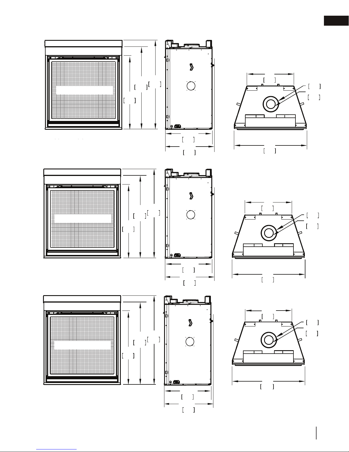
1.4 dimensions
general information
EN
SAFETY BARRIER
HD35-2 ILLUSTRATED
HD35-1 ILLUSTRATED
SAFETY BARRIER
33 3/4"
857mm
965mm
33 3/4"
857mm
38"
965mm
38"
41"
1041mm
41"
1041mm
”
20 7/8
530mm
”
21 7/8
556mm
23”
584mm
35 1/4”
895mm
28”
711mm
Ø
7 "
178mm
Ø
4 "
102mm
Ø
7 "
178mm
Ø
4 "
102mm
HD40-1 ILLUSTRATED
HD40-2 ILLUSTRATED
2
SAFETY BARRIER
HD46-2 ILLUSTRATED
HD46-1 ILLUSTRATED
2
965mm
33 3/4"
857mm
38"
41"
1041mm
”
20 7/8
530mm
”
21 7/8
556mm
”
20 7/8
530mm
”
21 7/8
556mm
40 1/4”
1022mm
34”
864mm
46 1/4”
1175mm
Ø
7 "
178mm
Ø
4 "
102mm
W415-2197 / B / 08.28.18
9
Page 10

EN
WARNING
2.0 venting requirements
!
• Risk of fi re. Maintain specifi ed air space clearances to vent pipe and appliance.
• The vent system must be supported every 3’(0.9m) for both vertical and horizontal runs. Use support ring assembly W0100067 or equivalent non-combustible strapping to maintain the minimum clearance to combustibles for both vertical and
horizontal runs. Spacers are attached to the inner pipe at predetermined intervals to maintain an even air gap to the outer
pipe. This gap is required for safe operation. A spacer is required at the start, middle, and end of each elbow to ensure this
gap is maintained. These spaces must not be removed.
This appliance uses a 4” (102mm) exhaust / 7” (178mm) air intake vent pipe system. Refer to the section applicable
to your installation.
For safe and proper operation of the appliance, follow the venting instructions exactly. Deviation from the minimum vertical
vent length can create diffi culty in burner start-up and/or carboning. Under extreme vent confi gurations, allow several minutes
(5-15) for the fl ame to stabilize after ignition. Although not a requirement, it is recommended for vent lengths that pass through
unheated spaces (attics, garages, crawl spaces) be insulated with the insulation wrapped in a protective sleeve to minimize
condensation. Provide a means for visually checking the vent connection to the appliance after the appliance is installed. Use a
fi restop, vent pipe shield or attic insulation shield when penetrating interior walls, fl oor or ceiling.
The vent terminal may be painted with a high temperature paint to match exterior colours. Use an outdoor paint suitable for
400°F (200°C). Application and performance of paint is the consumer’s responsibility. Spot testing is recommended.
note:
If for any reason the vent air intake system is disassembled, re-install per the instructions provided for the initial installation.
This appliance must be installed with a continuous connection of exhaust and air intake vent pipes. Utilizing alternate
constructions such as a chimney as part of the vent system is not permitted.
Use only Wolf Steel, Simpson Dura-Vent, Selkirk Direct Temp, American Metal Amerivent or Metal-Fab venting components.
Minimum and maximum vent lengths, for both horizontal and vertical installations, clearances from vent pipes to combustibles
and air terminal locations as set out in this manual apply to all vent systems and must be adhered to. For Simpson Dura-Vent,
Selkirk Direct Temp, American Metal Amerivent and Metal-Fab, follow the installation procedure provided with the venting
components or on the website for your venting supplier.
A starter adaptor must be used with the following vent systems and may be purchased from the corresponding supplier:
Vent
Manufacturer
Duravent W175-0053 Wolf Steel www.duravent.com
Amerivent 4DSC-N2 American Metal www.americanmetalproducts.com
Direct Temp 4DT-AAN Selkirk www.selkirkcorp.com
SuperSeal 4DNA Metal-Fab www.mtlfab.com
For vent systems that provide seals on the inner exhaust fl ue, only the outer air intake joints must be sealed using a red high
temperature silicone (RTV). This same sealant may be used on both the inner exhaust and outer intake vent pipe joints of all
other approved vent systems except for the exhaust vent pipe connection to the appliance fl ue collar which must be sealed
using the black high temperature sealant Mill Pac. High temperature sealant must be ordered separately.
When using Wolf Steel venting components, use only approved Wolf Steel rigid / fl exible components with the following termination kits: wall terminal kit GD-222, GD-222R, or 1/12 to 7/12 pitch roof terminal kit GD-110, 8/12 to 12/12 roof terminal
This template must be used in conjunction with templates 7.1.1 or 7.1.2, depending on
kit GD-111, fl at roof terminal kit GD-112 or periscope kit GD-201 (for wall penetration below grade). With fl exible venting, in
conjunction with the various terminations, use either the 5 foot (1.5m) vent kit GD-220 or the 10 foot (3.1m) vent kit GD-330.
termination shape (i.e. round, or round and square). See appropriate templates folder.
For stoves only: wall terminal kit GD-175 (venting included).
For optimum fl ame appearance and appliance performance, keep the vent length and number of elbows to a minimum.
The air terminal must remain unobstructed at all times. Examine the air terminal at least once a year to verify that
it is unobstructed and undamaged.
Rigid and fl exible venting systems must not be combined. Different venting manufacturer components must not
be combined.
These vent kits allow for either horizontal or vertical venting of the appliance. The maximum allowable horizontal run is 20
feet (6.1m). The maximum allowable vertical vent length is 40 feet (12.2m). The maximum number of vent connections is two
horizontally or three vertically (excluding the appliance and the air terminal connections) when using fl exible venting.
Starter Adapter Part Number Supplier Website
10
W415-2197 / B / 08.28.18
Page 11

!
WARNING
• Risk of fi re. Maintain specifi ed air space clearances to vent pipe and appliance.
• The vent system must be supported every 3’(0.9m) for both vertical and horizontal runs. Use support ring assembly W010-
0067 or equivalent non-combustible strapping to maintain the minimum clearance to combustibles for both vertical and
horizontal runs. Spacers are attached to the inner pipe at predetermined intervals to maintain an even air gap to the outer
pipe. This gap is required for safe operation. A spacer is required at the start, middle, and end of each elbow to ensure this
gap is maintained. These spaces must not be removed.
This appliance uses a 4” (102mm) exhaust / 7” (178mm) air intake vent pipe system. Refer to the section applicable
to your installation.
For safe and proper operation of the appliance, follow the venting instructions exactly. Deviation from the minimum vertical
vent length can create diffi culty in burner start-up and/or carboning. Under extreme vent confi gurations, allow several minutes
(5-15) for the fl ame to stabilize after ignition. Although not a requirement, it is recommended for vent lengths that pass through
unheated spaces (attics, garages, crawl spaces) be insulated with the insulation wrapped in a protective sleeve to minimize
condensation. Provide a means for visually checking the vent connection to the appliance after the appliance is installed. Use a
fi restop, vent pipe shield or attic insulation shield when penetrating interior walls, fl oor or ceiling.
The vent terminal may be painted with a high temperature paint to match exterior colours. Use an outdoor paint suitable for
400°F (200°C). Application and performance of paint is the consumer’s responsibility. Spot testing is recommended.
For vent systems that provide seals on the inner exhaust fl ue, only the outer air intake joints must be sealed using a red high
temperature silicone (RTV). This same sealant may be used on both the inner exhaust and outer intake vent pipe joints of all
other approved vent systems except for the exhaust vent pipe connection to the appliance fl ue collar which must be sealed
using the black high temperature sealant Mill Pac. High temperature sealant must be ordered separately.
For optimum fl ame appearance and appliance performance, keep the vent length and number of elbows to a minimum.
The air terminal must remain unobstructed at all times. Examine the air terminal at least once a year to verify that
it is unobstructed and undamaged.
Rigid and fl exible venting systems must not be combined. Different venting manufacturer components must not
be combined.
These vent kits allow for either horizontal or vertical venting of the appliance. The maximum allowable horizontal run is 20
feet (6.1m). The maximum allowable vertical vent length is 40 feet (12.2m). The maximum number of vent connections is two
horizontally or three vertically (excluding the appliance and the air terminal connections) when using fl exible venting.
Horizontal runs may have a 0” rise per foot or 0mm rise per meter however for optimum performance it is recommended
all around between the inner liner and outer liner is required for safe operation.
Vent
Manufacturer
Starter Adapter Part Number Supplier Website
Duravent W175-0053 Wolf Steel www.duravent.com
Amerivent 4DSC-N2 American Metal www.americanmetalproducts.com
Direct Temp 4DT-AAN Selkirk www.selkirkcorp.com
SuperSeal 4DNA Metal-Fab www.mtlfab.com
Use only Wolf Steel, Simpson Dura-Vent, Selkirk Direct Temp, American Metal Amerivent or Metal-Fab venting components.
Minimum and maximum vent lengths, for both horizontal and vertical installations, clearances from vent pipes to combustibles
and air terminal locations as set out in this manual apply to all vent systems and must be adhered to. For Simpson Dura-Vent,
Selkirk Direct Temp, American Metal Amerivent and Metal-Fab, follow the installation procedure provided with the venting
components or on the website for your venting supplier.
A starter adaptor must be used with the following vent systems and may be purchased from the corresponding supplier:
note:
If for any reason the vent air intake system is disassembled, re-install per the instructions provided for the initial installation.
This appliance must be installed with a continuous connection of exhaust and air intake vent pipes. Utilizing alternate
constructions such as a chimney as part of the vent system is not permitted.
This template must be used in conjunction with templates 7.1.1 or 7.1.2, depending on
termination shape (i.e. round, or round and square). See appropriate templates folder.
venting requirements
that all horizontal runs have a minimum 1/4” rise per foot or 21mm rise per meter using fl exible venting. For safe and proper
operation of the appliance, follow the venting instructions exactly.
A terminal shall not terminate directly above a sidewalk or paved driveway which is located between two single family dwellings
and serves both dwellings. Local codes or regulations may require different clearances.
Do not allow the inside liner to bunch up on horizontal or vertical runs and elbows. Keep it pulled tight. A 1¼” (31.8mm) air gap
EN
Horizontal runs may have a 0” rise per foot however for optimum performance it is recommended that all
horizontal runs have a minimum 1/4" (6mm) rise per foot using flexible or rigid venting. For safe and proper
operation of the appliance, follow the venting instructions exactly.
When terminating vertically, the vertical rise is a minimum 3 feet (1m) and a maximum 40 feet (12m) from the top of
the appliance.
W415-2197 / B / 08.28.18
11
Page 12
EN
venting requirements
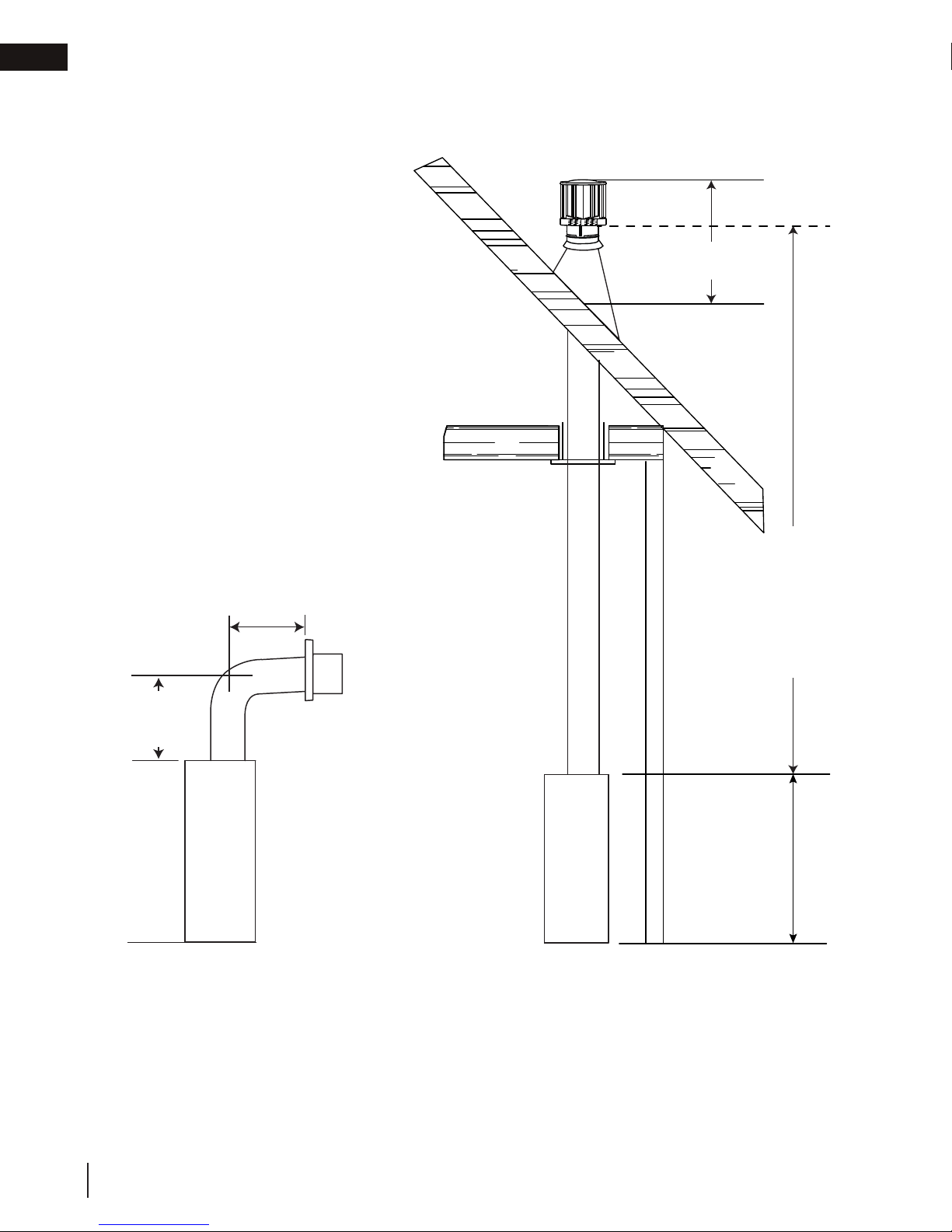
2.1 typical vent installations
16" (40.6cm)
minimum
19 1/2" (49.5cm)
minimum
24" (61cm)
maximum
40ft (12m)
maximum
3ft (1m)
minimum
* See “venting” section.
12
W415-2197 / B / 08.28.18
Page 13
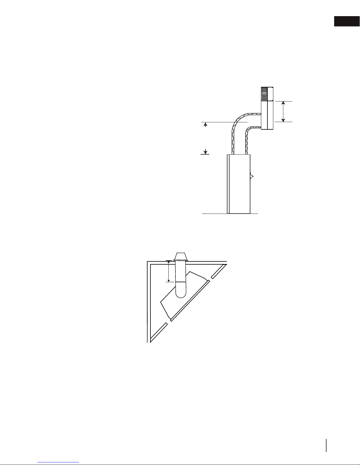
venting requirements
Use the periscope kit to locate the air termination above grade. The periscope must be installed so that when
2.2 special vent installations
2.2.1 periscope termination
fi nal grading is completed, the bottom air slot is located a minimum 12” (305mm) above grade. The maximum
allowable vent length (including both rise and run) is 10’ (3m) for a fi replace and 8’ (2m) for a stove. An insulation
sleeve is illustrated in the top vent image below, use only when supplied with the appliance.
(The insulation sleeve is not required with a stove appliance)
12" (30.5cm)
minimum to
30"
(76.2cm)
minimum
EN
grade
2.2.2 corner termination
The maximum vent length for a corner installation is 20" (50.8cm) of horizontal run with a minimum 19 1/2"
(49.5cm) rise.
20” (508mm)
MAX
MAX.
20”
(50.8cm)
W415-2197 / B / 08.28.18
13
Page 14

EN
Covered balcony applications ††*
venting requirements
2.3 minimum air terminal location clearances
Q
R
S
P
G
Q
= 3 feet
MIN
(0.9m)
INSTALLATIONS
CANADA U.S.A.
12” (30.5cm) 12” (30.5cm) Clearance above grade, veranda porch, deck or balcony.
A
18”
Δ
9” (229mm) ΔClearance to windows or doors that open.
18”
(45.7cm)**
Vertical clearance to ventilated soffi ts located above the terminal within a horizontal distance of 2’ (0.6m)
from the center line of the terminal.
Clearance to an inside non-combustible corner wall or protruding non-combustible obstructions (chimney, etc.).
Clearance to each side of the center line extended above the meter / regulator assembly to a maximum
vertical distance of 15’ (4.6m).
12” (30.5cm)
B
12” (30.5cm)* 12” (30.5cm)* Clearance to permanently closed windows.
C
D
(45.7cm)**
12” (30.5cm)** 12” (30.5cm)** Clearance to unventilated soffi t.
E
0” (0mm) 0” (0mm) Clearance to an outside corner wall.
F
0” (0mm)*** 0” (0mm)***
G
2” (51mm)*** 2” (51mm)*** Clearance to an inside combustible corner wall or protruding combustible obstructions (vent chase, etc.).
H
K
M
3’(0.9m) 3’(0.9m)****
3’ (0.9m) 3’ (0.9m)**** Clearance to a service regulator vent outlet.
I
12” (30.5cm) 9” (229mm) Clearance to a non-mechanical air supply inlet to the building or a combustion air inlet to any other appliance.
J
6’ (1.8m) 3’ (0.9m) † Clearance to a mechanical air supply inlet.
7’ (2.1m) ‡ 7’ (2.1m) **** Clearance above a paved sidewalk or paved driveway located on public property.
L
12” (30.5cm)†† 12” (30.5cm)**** Clearance under a veranda, porch or deck.
note:
Wall terminals are for illustration purposes only. Size and
shapes may vary.
R
= 2 x
MAX
Q
ACTUAL
R
MAX
≤ 15 feet
(4.6m)
16” (40.6cm) 16” (40.6cm) Clearance above the roof.
N
2’ (0.6m)†* 2’ (0.6m) †* Clearance from an adjacent wall including neighbouring buildings.
O
8’ (2.4m) 8’ (2.4m)
P
3’ (0.9m) 3’ (0.9m) See chart for wider wall dimensions.
Q
6’ (1.8m) 6’ (1.8m)
R
12” (30.5cm) 12” (30.5cm) Clearance under a covered balcony
S
Δ The terminal shall not be located less than 6 feet under a window that opens on a horizontal plane in a structure with three walls and a roof.
* Recommended to prevent condensation on windows and thermal breakage
** It is recommended to use a heat shield and to maximize the distance to vinyl clad soffi ts.
*** The periscope requires a minimum 18 inches clearance from an inside corner.
**** This is a recommended distance. For additional requirements, check local codes.
† 3 feet above if within 10 feet horizontally.
‡ A vent shall not terminate where it may cause hazardous frost or ice accumulations on adjacent property surfaces.
†† Permitted only if the veranda, porch, or deck is fully open on a minimum of two sides beneath the fl oor.
†* Recommended to prevent recirculation of exhaust products. For additional requirements, check local codes.
††* Permitted only if the balcony is fully open on a minimum of one side.
14
W415-2197 / B / 08.28.18
Roof must be non-combustible without openings.
See chart for deeper wall dimensions. The terminal shall not be installed on any wall that has an opening
between the terminal and the open side of the structure.
note:
Clearances are to be in accordance with local
installation codes and the requirements of the gas
supplier. In their absence, clearances are to be as
listed above and are based on national codes.
Page 15

2.4 vent application flow chart
VT - combined vertical vent lengths in feet
TOP EXIT
venting requirements
EN
Horizontal Termination
Vertical rise is equal
to or greater than
the horizontal run
Horizontal run +
vertical rise to
maximum of
35 feet (10.7m)
Vertical rise is less
than horizontal run
Horizontal run +
vertical rise to
maximum of 24.75
feet (7.5m)
4.2 times the
vertical rise equal to
or greater than the
horizontal run
2.5 definitions
For the following symbols used in the venting calculations and
examples are:
> - greater than
> - equal to or greater than
< - less than
< - equal to or less than
HT - total of both horizontal vent lengths (Hr) and offsets (Ho) in feet
HR - combined horizontal vent lengths in feet
HO - offset factor: .03 (total degrees of offset - 90°*) in feet
HO - offset factor: .03 (total degrees of offset - 135°*) in feet
Vertical Termination
Vertical rise is equal
to or greater than
the horizontal run
Horizontal run +
vertical rise to
maximum of
35 feet (10.7m)
Vertical rise is less
than horizontal run
Horizontal run +
vertical rise to
maximum of
35 feet (10.7m)
3 times the vertical
rise equal to or
greater than the
horizontal run
2.6 elbow vent lengths
Feet Inches Millimeters
1° 0.03 0.5 12.7
15° 0.45 6.0 152.4
30° 0.9 11.0 279.4
45° 1.35 16.0 406.4
90°* 2.7 32.0 812.8
* The fi rst 90° offset has a zero value and is shown in the formula as - 90°
* The fi rst 45° and° offset have a zero value and is shown in the formula as -45° and -90° respectively
or -135° when combined (for 45° exit only).
W415-2197 / B / 08.28.18
15
Page 16
EN
0
2.5
(0.8)5(1.5)
7.5
(2.3)
10
(3.1)
12.5
(3.8)15(4.6)
40 (12.2)
10 (3.1)
20 (6.1)
30 (9.1)
17.5
(5.3)20(6.1)
39 (11.9)
REQUIRED
VERTICAL
RISE IN FEET
(METERS)V
T
HORIZONTAL VENT RUN PLUS OFFSET IN FEET
(METERS) H
T
7.5
(2.3)
10
(3.1)
12.5
(3.8)15(4.6)
17.5
(5.3)20(6.1)
(METERS) H
T
venting requirements
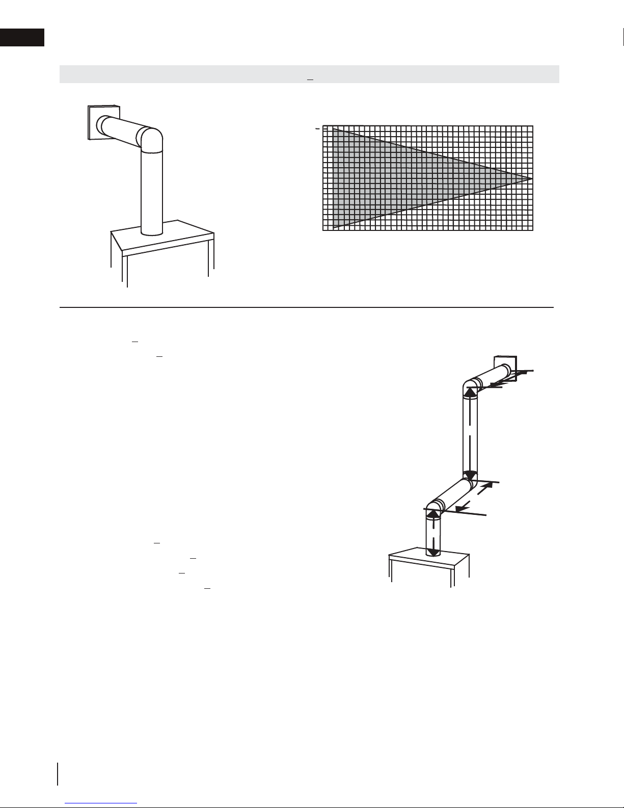
2.7 horizontal termination
(HT) < (VT)
Simple venting configuration (only one 90° elbow)
See graph to determine the required vertical rise
VT for the required horizontal run HT.
40 (12.2)
39 (11.9)
REQUIRED
30 (9.1)
VERTICAL
RISE IN FEET
(METERS)V
20 (6.1)
T
10 (3.1)
0
2.5
(0.8)5(1.5)
7.5
(2.3)
(3.1)
10
12.5
(3.8)15(4.6)
HORIZONTAL VENT RUN PLUS OFFSET IN FEET
(METERS) H
T
The shaded area within the lines represents ac-
ceptable values for HT and V
For vent configurations requiring more than one 90° elbow, the following formulas apply:
Formula 1: HT < V
T
Formula 2: HT + VT < 40 feet (12.2m)
Example:
90°
V1 = 3 FT (0.9m)
V2 = 8 FT (2.4m)
VT = V1 + V2= 3 FT (0.9m ) + 8 FT (2.4m) = 11 FT (3.4m)
H1 = 2.5 FT (0.8m)
H2 = 2 FT (0.6m)
HR = H1 + H2 = 2.5 FT (0.8m) + 2 FT (0.6m) = 4.5 FT (1.4m)
HO = .03 (three 90° elbows - 90°) = .03 (270° - 90°) = 5.4 FT (1.7m)
HT = HR + HO = 4.5 FT (1.4m) + 5.4 FT (1.6m) = 9.9 FT (3m)
HT + VT = 9.9 FT (3m) + 11 FT (3.4m) = 20.9 FT (6.4m)
Formula 1: HT < V
T
90°
90°
V
1
9.9 FT (3m) < 11 FT (3.4m)
Formula 2: HT + VT < 40 FT (12.2m)
20.9 FT (6.4m) < 40 FT (12.2m)
Since both formulas are met, this vent configuration is acceptable.
17.5
(5.3)20(6.1)
T
H
2
V
2
H
1
16
W415-2197 / B / 08.28.18
Page 17

(HT) > (VT)
Simple venting configuration (only one 90° elbow)
for the
For vent configurations requiring more than one 90° elbow, the following formulas apply:
Formula 1:
Formula 2:
Example:
V
H
H
H
H
H
H
Formula 1:
4.2 V
10.7
Formula 2:
Since both formulas are met, this vent configuration is acceptable.
Example:
V
V
V
H
H
H
H
H
H
H
H
Formula 1:
4.2 V
Formula 2:
Since both formulas are met, this vent configuration is acceptable.
venting requirements
See graph to determine the required vertical rise V
required horizontal run HT.
150 (381)
150 (3810)
147
147
(373.4)
(3733.8)
EN
T
REQUIRED
VERTICAL RISE
100 (254)
100 (2540)
IN INCHES
(CENTIMETERS)
V
T
57 (144.8)
57 (1447.8)
19 1/2
19 1/2
(495.3)
(49.5)
50 (127)
50 (1270)
HORIZONTAL VENT RUN PLUS OFFSET IN FEET (METERS) H
The shaded area within the lines represents acceptable
HT < 4.2 V
HT + V
= VT = 6 FT (1.8m)
1
= 3 FT (0.9m)
1
= 5 FT (1.5m)
2
= H
+ H
R
= .03 (two 90° elbows - 90°) = .03 (180° - 90°) = 2.7FT (0.8m)
O
= H
T
+ V
T
= 3FT (0.9m) + 5FT (1.5m) = 8 FT (2.4m)
1
2
+ H
= 8FT (2.4m) + 2.7FT (0.8m) = 10.7FT (3.3m)
R
O
= 10.7FT (3.3m) + 6FT (1.8m) = 16.7FT (5.1m)
T
T
< 24.75 feet (7.5m)
T
90°
V
1
HT < 4.2 V
HT + V
16.7FT (5.1m) < 24.75 (7.5m)
T
= 4.2FT (1.3m) x 6FT (1.8m) = 25.2FT (7.7m)
T
FT (3.3m) < 25.2FT (7.7m)
< 24.75 FT (7.5m)
T
90°
= 4 FT (1.2m)
1
= 1.5 FT (0.5m)
2
= V
+ V
T
= 2 FT (0.6m)
1
= 1 FT (0.3m)
2
= 1 FT (0.3m)
3
= 1.5 FT (0.5m)
4
= H
R
= .03 (four 90° elbows - 90°) = .03 (360° - 90°) = 8.1 FT (2.5m)
O
= H
T
+ V
T
= 4FT (1.2m) + 1.5FT (0.5m) = 5.5 FT (1.7m)
1
2
+ H2 + H
1
+ H
R
= 13.6 FT (4.2m) + 5.5 FT (1.7m) = 19.1 FT (5.8m)
T
+ H4 = 2FT (0.6m) + 1FT (0.3m) + 1FT (0.3m) + 1.5FT (0.5m) = 5.5 FT (1.7m)
3
= 5.5 FT (1.7m) + 8.1 FT (2.5m) = 13.6 FT (4.2m)
O
V
1
HT < 4.2 V
13.6 FT (4.2m) < 23.1 FT (7m)
HT + V
19.1FT (5.8m) < 24.75 FT (7.5m)
T
= 4.2 FT (1.3m) x 5.5 FT(1.7m) = 23.1 FT (7m)
T
< 24.75 FT (7.5m)
T
5
0
5
0
(1.5)
2
(1.5)
2
(0.6)
(0.6)
values for H
H
1
90°
10
10
(3.1)
12.5
(3.1)
12.5
(3.8)
(3.8)
and VT
T
H
1
90°
90°
15
15
(4.6)
(4.6)
H
2
19.5
19.5
(5.9)
(5.9)
90°
20 (6.1)
20 (6.1)
H
3
T
H
2
H
V
2
4
W415-2197 / B / 08.28.18
17
Page 18
EN
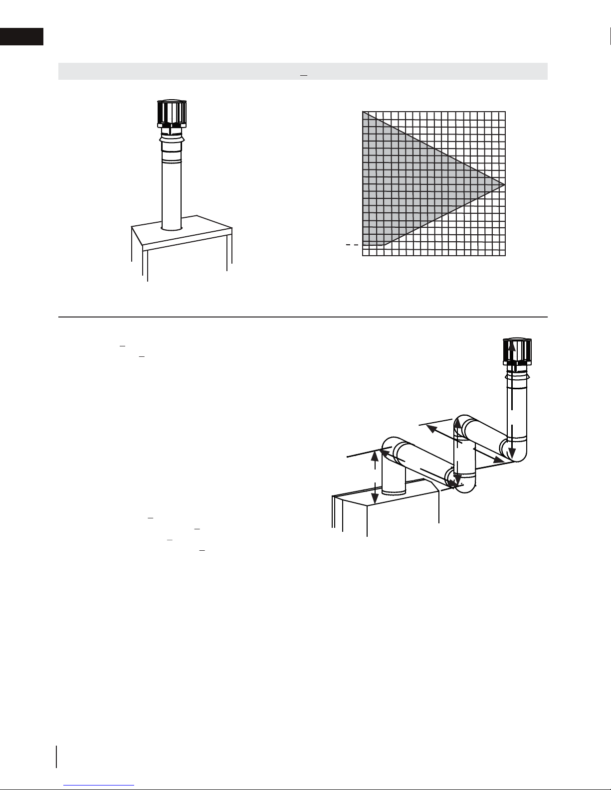
(HT) < (VT)
Since both formulas are met, this vent configuration is acceptable.
venting requirements
2.8 vertical termination
Simple venting configurations.
For vent configurations requiring one or more 90° elbows the following formulas apply:
Formula 1: H
Formula 2: HT + V
< V
T
T
< 40 feet (12.2m)
T
See graph to determine the required vertical rise V
required horizontal run H
40 (12.2)
30 (9.1)
.
T
REQUIRED
VERTICAL
RISE IN FEET
(METERS) V
T
3 (0.9)
20 (6.1)
10 (3.1)
0
5
(1.5)
10
(3.1)
15
(4.6)
20
(6.1)
HORIZONTAL VENT RUN PLUS OFFSET IN FEET (METERS) H
The shaded area within the lines represents acceptable
values for H
and VT
T
for the
T
T
Example:
= 5 FT (1.5m)
V
1
V
= 6 FT (1.8m)
2
= 10 FT (3.1m)
V
3
= V
V
H
H
H
H
= .03 (360° - 90°) = 8.1 FT (2.5m)
H
H
Formula 1: H
18.6FT (5.7m) < 21FT (6.4m)
Formula 2: HT + V
39.6FT (12.1m) < 40FT (12.2m)
+ V2 + V3 = 5FT (1.5m) + 6FT (1.8m) + 10FT (3.1m) = 21FT (6.4m)
T
1
= 8 FT (2.4m)
1
= 2.5 FT (0.8m)
2
= H
+ H
R
= .03 (four 90° elbows - 90°)
O
= H
T
+ V
T
= 8FT (2.4m) + 2.5FT (0.8m) = 10.5 FT (3.2m)
1
2
+ H
= 10.5FT (3.2m) + 8.1FT (2.5m) = 18.6FT (5.7m)
R
O
= 18.6FT (5.7m) + 21FT (6.4m) = 39.6FT (12.1m)
T
< V
T
T
< 40 FT (12.19m)
T
90°
V
3
90°
H
2
V
H
1
V
1
2
90°
90°
18
W415-2197 / B / 08.28.18
Page 19
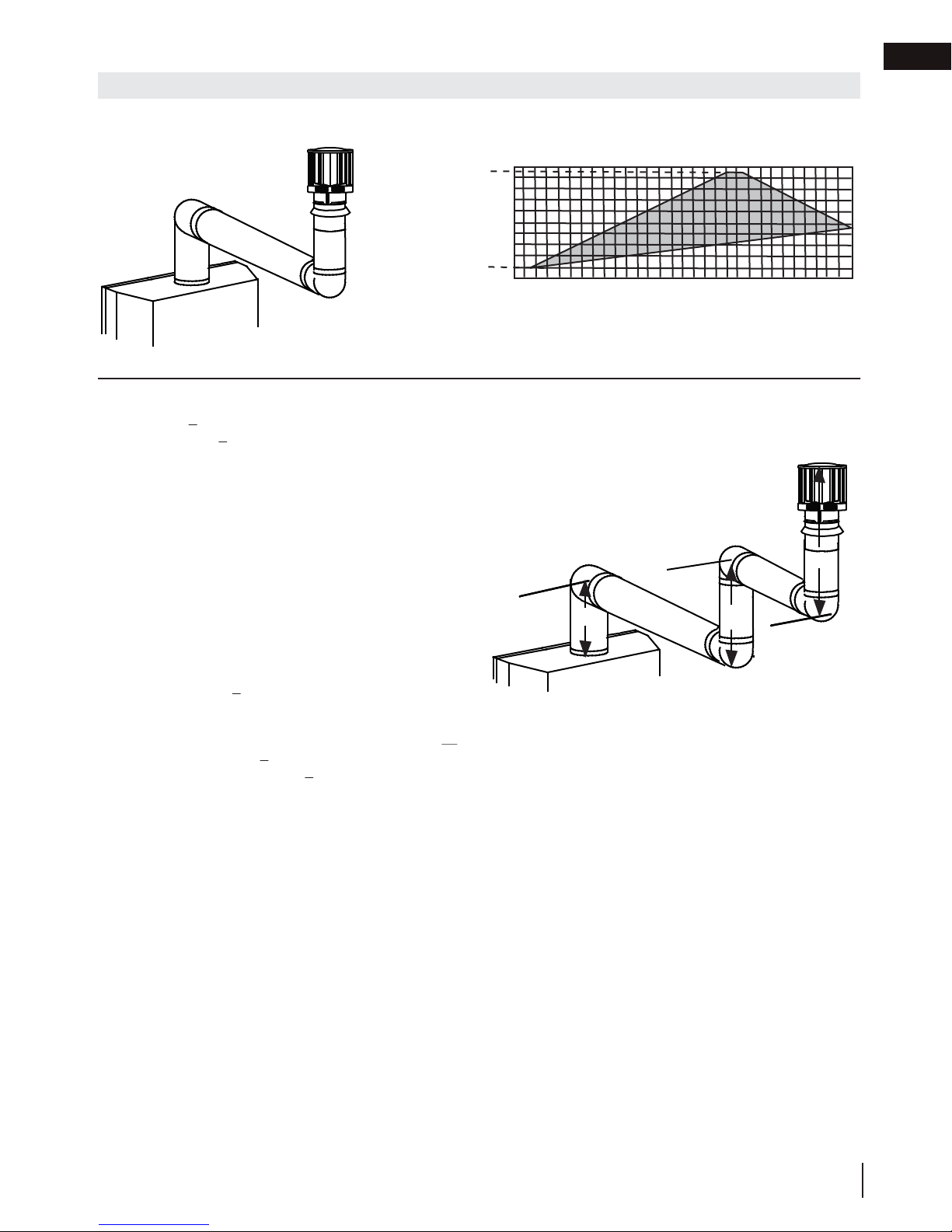
venting requirements
(HT) > (VT)
for the
16.1FT (4.9m) > 13.5
Since this formula is not met, this vent configuration is
will need to be established to satisfy both formulas.
30
Simple venting configurations.
REQUIRED
VERTICAL
RISE IN FEET
(METERS) V
T
HORIZONTAL VENT RUN PLUS OFFSET IN FEET (METERS) H
For vent configurations requiring more than two 90° elbows the following formulas apply:
Formula 1: H
Formula 2: HT + V
< 3V
T
T
< 40 feet (12.2m)
T
Example:
= 2 FT (0.6m)
V
1
V
= 1 FT (0.3m)
2
= 1.5 FT (0.5m)
V
3
= V1+V2+V3= 2FT (0.6m) + 1FT (0.3m) + 1.5FT (0.5m) = 4.5FT (1.4m)
V
T
H
= 6 FT (1.8m)
1
= 2 FT (0.6m)
H
2
H
= H
+ H
R
= .03 (four 90° elbows - 90°)
H
O
= .03 (360° - 90°) = 8.1 FT (2.5m)
H
= H
T
+ V
H
T
Formula 1: H
3VT = 3FT (0.9m) x 4.5FT (1.4m) = 13.5FT (4.1m)
= 6FT (1.8m) + 2FT (0.6m) = 8 FT (2.4m)
1
2
+ H
= 8FT (2.4m) + 8.1FT (2.5m) = 16.1FT (4.9m)
R
O
= 16.1FT (4.9m) + 4.5FT (1.4m) = 20.6 FT (6.3m)
T
< 3V
T
T
FT (4.1m)
unacceptable.
Formula 2: HT + VT < 40 feet (12.2m)
20.6FT (6.3m) < 40 (12.2m)
Since only formula 2 is met, this vent configuration is unacceptable and a new appliance location or vent configuration
See graph to determine the required vertical rise V
required horizontal run HT.
20 (6.1)
19 (5.8)
10 (3.1)
3 (0.9)
0
5
(1.5)
10
(3.1)
15
(4.6)
20
(6.1)
The shaded area within the lines represents acceptable
values for H
and VT
T
90°
90°
H
V
1
1
V
2
90°
T
25
(7.6)
V
H
2
3
(9.1)
T
90°
EN
W415-2197 / B / 08.28.18
19
Page 20

EN
!
WARNING
venting requirements
2.9 co-axial to co-linear venting
• Risk of fi re.
• Co-axial to co-linear venting confi gurations must only be used in a non-combustible chimney or enclosure.
Installation in a combustible enclosure could result in a fi re.
This appliance is designed to be attached to a 3” (76.2mm) co-linear aluminum fl ex vent system running the full
length of a masonry chimney.
The fl ex liners accommodate any contours of a
masonry chimney, however, it is necessary to keep
the fl exible liners as straight as possible. The inlet
air collar of the termination cap must be connected
to the air intake fl ex liner and the exhaust collar
must be connected to the exhaust fl exible liner.
Both Simpson Duravent and Selkirk co-linear to
co-axial adaptors have been approved on this
appliance
AIR
INTAKE
TERMINATION
EXHAUST
FLUE
FLEX
LINER
note:
A vent adaptor will be required directly off the appliance.
Follow vent manufacturer’s installation instructions.
Different manufacturer’s venting
components must not be combined.
Once the preferred manufacturer’s
appliance adaptor has been attached, the
remainder of the system must be that of
the same manufacturer.
The only exception to this rule is to use
Wolf Steel’s approved 3” (76.2mm) fl ex
liner and co-linear termination.
* Measured from appliance fl ue collar
to termination fl ue collar
* 40 FT (12.2m)
MAX.
10 FT (3.1m)
MIN
COAXIAL TO
CO-LINEAR
ADAPATOR
APPLIANCE
VENT ADAPTOR
20
W415-2197 / B / 08.28.18
Page 21

3.0 rough framing
!
WARNING
note:
When using optional fi nishing accessories, the framing dimensions and fi nishing materials may differ from
what is outlined in the section below; refer to the leafl et instructions supplied in the accessory kit for specifi c
framing and fi nishing specifi cations.
• Risk of fi re!
• In order to avoid the possibility of exposed insulation or vapour barrier coming in contact with the appliance
body, it is recommended that the walls of the appliance enclosure be “fi nished” (i.e. drywall / sheetrock),
as you would fi nish any other outside wall of a home. This will ensure that clearance to combustibles is
maintained within the cavity.
• Do not notch the framing around the appliance stand offs. Failure to maintain air space clearance may cause
over heating and fi re. Prevent contact with sagging or loose insulation or framing and other combustible
materials. Block opening into the chase to prevent entry of blown-in insulation. Make sure insulation and
other materials are secured.
• When constructing the enclosure, allow for fi nishing material thickness to maintain clearances. Framing or
fi nishing material closer than the minimums listed must be constructed entirely of non-combustible materials.
Materials consisting entirely of steel, iron, brick, tile, concrete, slate, glass or plasters, or any combination
thereof are suitable. Materials that are reported as passing ASTM E136, standard test method for behaviour
of materials in a vertical tube furnace at 1382ºF (750ºC) and UL763 shall be considered non-combustible
materials.
• Minimum clearance to combusibles must be maintained or a serious fi re hazard could result.
• The appliance requires a minimum enclosure height. Measure from the appliance base.
• If steel stud framing kits with cement board are provided, or specifi ed in the installation instructions, they
must be installed.
• If specifi ed in the installation instruction, fi nishing must be done using a non-combustible board, ceramic tile,
marble, etc. Do NOT use wood or drywall. Any fi re rated drywall is not acceptable.
EN
It is best to frame your appliance after it is positioned and the vent system is installed. Frame to local building codes.
It is not necessary to install a hearth extension with this appliance.
When roughing in the appliance, raise the appliance to accommodate for the thickness of the finished floor materials,
i.e. tile, carpeting, hard wood, which if not planned for will interfere with the opening of the lower access door and the
installation of many decorative flashing accessories.
Combustible materials may be installed flush with the front of the appliance but must not cover any of the black
face-areas of the appliance. Non-combustible material (brick, stone or ceramic tile) may protrude in these areas.
W415-2197 / B / 08.28.18
21
Page 22

EN
Do not put objects in front of the appliance
(minimum distance of 4 feet)
rough framing
3.1 minimum framing dimensions
HORIZONTAL VENT SECTIONS: A minimum clearance of 1" (25mm) at the bottom and sides and 2" (51mm)
at the top of the vent pipe in all horizontal runs to combustibles is required except for clearances in appliance
enclosures. Horizontal vent sections within enclosures require a minimum clearance of 9” (229mm) at the top of
the vent pipe (see “minimum enclosure clearances” section). Use firestop spacer W010-1777 (supplied) where
vent pipe penetrates combustible walls.
VERTICAL VENT SECTIONS: A minimum clearance of 1" (25mm) all around the vent pipe on all vertical runs to
combustibles is required except for clearances in appliance enclosures. Vertical vent sections within enclosures
require a minimum clearance of 4" (102mm) to the sides of the vent pipe (see “minimum enclosure clearances”
section). Use firestop spacer W500-0292 (not supplied) where vent pipe penetrates combustible ceilings or floors.
2"
(51mm)
C
D
A
A
B
E
F
Ref HD35-2 HD40-2 HD46-2
A
B
C
22
W415-2197 / B / 08.28.18
D
E
F
35 3/4" (90.8cm) 40 3/4" (103.5cm) 46 3/4" (118.7cm)
61 1/2" (156.2cm) 66 1/2" (168.9cm) 72 1/2" (184.2cm)
43 1/2" (110.5cm) 47" (119.4cm) 51 1/4" (130.2cm)
14 13/16" (37.6cm) 16 9/16" (42.1cm) 18 11/16" (47.5cm)
32 3/4" (83.2cm) 35 1/4" (89.5cm) 38 1/4" (97.2cm)
22 1/4" (56.5cm) 22 1/4" (56.5cm) 22 1/4" (56.5cm)
MINIMUM ENCLOSURE CLEARANCES
Page 23

3.2 minimum enclosure clearances
COMBUSTIBLE
FIRESTOP SPACER
6”
152mm
6 1/2”
165mm
9”
229mm
NON-COMBUSTIBLE
BRICK
2”
51mm
1”
25mm
rough framing
0” IF NON-COMBUSTIBLE
FINISHING IS USED
SUCH AS BRICK AND
STONE.
EN
70”
177.8cm
MINIMUM
38”
96.5cm
33 3/4”
85.7cm
For temperature requirements, the enclosure space around and above the appliance must be left unobstructed.
It is recommended that the enclosure be ventilated at the top and bottom to circulate the hot air.
NON-COMBUSTIBLE
MATERIAL
FRONT HOOD
1”
25mm
57 1/2”
146cm
MINIMUM
PLUS RISE*
* See “venting” section.
W415-2197 / B / 08.28.18
23
Page 24

EN
rough framing
note:
For heavier finishing materials such as marble, we recommend adding extra support to the frame. Ensure
there is adequate floor support for the appliance and finishing material.
Before framing your appliance, determine vent requirements before deciding the final location of the appliance.
After rough framing, place the appliance in its final position.
A
Minimum Rough Framing Dimensions
Ref. HD35-2 HD40-2 HD46-2
22 1/4” (56.5cm) 22 1/4” (56.5cm) 22 1/4” (56.5cm)
A
35 3/4”* (90.8cm) 40 3/4”* (103.5cm) 46 3/4”* (118.7cm)
B
* Based on 1/2” (12.7mm) finishing material thickness.
B
24
W415-2197 / B / 08.28.18
Page 25

4.0 venting installation
!
WARNING
• Ensure to unpack all loose materials from inside the fi rebox prior to connecting the gas and electrical supply
• If your appliance is supplied with a remote, ensure the remote receiver is in the “OFF” position prior
to connecting the gas and electrical supply to the appliance.
• For safe and proper operation of the appliance, follow the venting instructions exactly.
• The appliance exhaust fl ue collar must be sealed using Mill Pac. All exhaust and intake vent pipe joints
must be sealed using red RTV high temp silicone sealant (W573-0002) (not supplied) or black high temp Mill
Pac (W573-0007) (not supplied).
• If using pipe clamps to connect rigid vent components, a minimum of 3 screws must also be used to ensure
the connection cannot slip off.
• Do not clamp the fl exible vent pipe.
• Risk of fi re, explosion, or asphyxiation. Improper support of the entire venting system may allow vent to sag
and separate. Use vent run supports and connect vent sections per installation instructions.
• Risk of fi re, do not allow loose materials or insulation to touch the vent pipe. Remove insulation to allow for the
installation of the attic shield and to maintain clearances to combustibles.
• Do not fi ll the space between the vent pipe and enclosure with any type of material. Do not pack insulation
or combustibles between ceiling fi restops. Always maintain specifi ed clearances around venting and fi restop
systems. Install wall shields and fi restops as specifi ed. Failure to keep insulation or other materials away from
vent pipe may cause fi re.
For optimum performance it is recommended that all horizontal runs have a minimum 1/4" (6mm) rise per foot
using flexible or rigid venting. For safe and proper operation of the appliance, follow the venting instructions
exactly.
EN
W415-2197 / B / 08.28.18
25
Page 26

EN
This application occurs when venting through a roof. Installation kits for
insulation, from fi lling up the 1" (25mm) air space around the pipe.
WARNING
venting installation
4.1 horizontal installation
!
• The fi restop assembly must be installed with the vent shield to the top.
• Terminals must not be recessed into a wall or siding more than the depth of the return fl ange of the mounting
plate.
This application occurs when venting through an exterior
wall. Having determined the correct height for the air
terminal location, cut and frame a hole in the exterior wall,
as illustrated, to accommodate the fi restop assembly. Dry
fi t the fi restop assembly before proceeding to ensure the
brackets on the rear surface fi t to the inside surface of the
horizontal framing.
The length of the vent shield may be cut shorter for
combustible walls that are less than 8 1/2” (215.9mm)
thick but the vent shield must extend the full depth of the
combustible wall.
note:
Do not fi ll the air space between the fi restop spacer and the
exterior wall with any type of insulating material (i.e. spray foam).
A. Apply a bead of caulking (not supplied) around the outer edge of
the hole of the fi restop assembly, fi t the fi restop assembly to the
hole and secure using 4 screws.
B. Once the vent pipe is installed in its fi nal position, apply red RTV silicone (W573-0002) (not supplied)
between the pipe and the fi restop.
4.2 vertical installation
various roof pitches are available from your authorized dealer / distributor.
See the “accessories” section to order specifi c kits required.
A. Determine the air terminal location, cut and frame a square opening,
as illustrated, in the ceiling and the roof to provide the minimum 1"
(25mm) clearance between the vent pipe and any combustible material.
Try to center the vent pipe location midway between two joists to
prevent having to cut them. Use a plumb bob to line up the center of
the openings. A vent pipe shield will prevent any materials such as
insulation, from fi lling up the 1" (25mm) air space around the pipe. Nail
headers between the joist for extra support.
B. Apply a bead of caulking (not supplied) to the framework or to the
Wolf Steel vent pipe shield plate or equivalent (in the case of a fi nished
ceiling), and secure over the opening in the ceiling. A fi restop must be
placed on the bottom of each framed opening in a roof or ceiling that
the venting system passes through. Apply a bead of caulking all around
and place a fi restop spacer over the vent shield to restrict cold air from
being drawn into the room or around the fi replace. Ensure that both
spacer and shield maintain the required clearance to combustibles.
Once the vent pipe is installed in its fi nal position, apply red RTV
silicone (W573-0002) (not supplied) between the pipe and the fi restop
assembly.
C. In the attic, slide the vent pipe collar down to cover up the open end
of the shield and tighten. This will prevent any materials, such as
CAULKING
FIRESTOP
SPACER
CAULKING
ADD
7”
VENT
SHIELD
note:
The above is for illustration purposes only. Vents
do not always pass through center of frame.
HEIGHT
(178mm)
FINISHING
MATERIAL
6”
ADD
(152mm)
WIDTH
DETERMINE
THE
CORRECT
HEIGHT
9 3/4”
(248mm)
Firestop
underside
of joist
Vent Pipe
Caulking
Shield
Vent
Pipe
Collar
Vent
Pipe
Shield
9 3/4”
(248mm)
26
W415-2197 / B / 08.28.18
Page 27

venting installation
“Wolf Steel Approved Venting” or “E2” as identifi ed by the stamp only on the fl ex pipes.
!
WARNING
A. Stretch the inner fl ex pipe to the required length taking
depth of its return fl ange.
ADD FASTENER TYPE
4.3 using either flexible or rigid vent components
• Do not allow the inner fl ex pipe to bunch up on horizontal or vertical runs and elbows. Keep it pulled tight.
• Spacers are attached to the inner fl ex pipe at predetermined intervals to maintain an even air gap to the outer
fl ex pipe. This gap is required for safe operation. A spacer is required at the start, middle, and end of each
elbow to ensure this gap is maintained. These spacers must not be removed.
For safe and proper operation of the appliance, follow the venting instructions
exactly.
Elbow
Spacers
The vent system must be supported approximately every 3 feet (0.9m) for
both vertical and horizontal runs. Use Wolf Steel Ltd. support ring assembly
or equivalent noncombustible strapping to maintain the minimum clearance to
combustibles for both vertical and horizontal runs.
All inner fl ex pipe and outer fl ex pipe joints may be sealed using high temperature
red RTV silicone W573-0002 (not supplied) or the high temperature sealant W5730007 Mill Pac (not supplied). However, the high temperature sealant W573-0007
Mill Pac (not supplied) must be used on the joint connecting the inner fl ex pipe and
the exhaust fl ue collar.
Use only approved fl exible vent pipe kits marked:
EN
4.3.1 horizontal air terminal installation
into account the additional length needed for the fi nished
wall surface. Apply a heavy bead of the red RTV silicone
(W573-0002) (not supplied) to the inner sleeve of the air
terminal. Slip the vent pipe a minimum of 2” (50.8mm)
B. Using the outer fl ex pipe, slide over the outer combustion
C. Insert the vent pipes through the fi restop maintaining
D. If more vent pipe needs to be used to reach the fi replace,
E. Stove Appliances Only: From inside the house, using
The air terminal mounting plate may be recessed into the exterior wall or siding no greater than the
over the inner sleeve of the air terminal and secure with a
minimum of 3 screws.
air sleeve of the air terminal and secure with a minimum
of 3 screws. Seal using red RTV silicone (W573-0002)
(not supplied).
the required clearance to combustibles. Holding the air
terminal (lettering in an upright, readable position), secure
to the exterior wall and make weather tight by sealing
with caulking (not supplied).
couple them together, as illustrated. The vent system
must be supported approximately every 3 feet (0.9m) for
both vertical and horizontal runs. Use non-combustible
strapping to maintain the minimum clearance to
combustibles.
Red RTV Silicone (W573-0002) (not supplied), seal
between the vent pipe and the fi restop. Then slide the black trim collar over the vent pipe up to the
fi restop.
Caulking
Screws
(Supplied)
ADD GRAPHIC
Red RTV Silicone
Outer Flex
Pipe
Inner Flex
Pipe
2" (50.8mm) Overlap
Red RTV Silicone
Inner Flex
Pipe
Outer Flex Pipe
Screws
Inner Coupler
Outer Coupler
Outer Flex
Pipe
W415-2197 / B / 08.28.18
27
Page 28

EN
air terminal installation” section.
!
WARNING
venting installation
4.3.2 vertical air terminal Installation
• Maintain a minimum 2” (51mm) space between the air inlet base and the storm collar.
note:
Fastening hardware provided with appropriate roof terminal and liner kits.
A. Fasten the roof support to the roof using 6 screws. The roof support is
optional. In this case, the venting is to be adequately supported using
either an alternate method suitable to the authority having jurisdiction or
the optional roof support.
B. Stretch the inner fl ex pipe to the required length. Slip the inner fl ex
pipe a minimum of 2” (51mm) over the inner pipe of the air terminal
connector and secure with a minimum of three screws, when 4/7, 5/8
and 3/5 venting is used and a minimum of six screws when using 8/10
or 8/11 venting. Seal using a heavy bead of red RTV silicone sealant
(W573-0002) (not supplied).
C. Repeat using the outer fl ex pipe, using a heavy bead of red RTV
silicone sealant (W573-0002) (not supplied) and a minimum of three
screws, when 4/7, 5/8 and 3/5 venting is used and a minimum of six
screws when using 8/10 or 8/11 venting.
D. Thread the air terminal connector / vent pipe assembly down through
the roof. The air terminal must be positioned vertically and plumb.
Attach the air terminal connector to the roof support, ensuring that the
top of the air terminal is 16” (40.6cm) above the highest point that it
penetrates the roof.
E. Remove nails from the shingles, above and to the sides of the air
terminal connector. Place the fl ashing over the air terminal connector
leaving a min. 3/4” (19mm) of the air terminal connector showing above
the top of the fl ashing. Slide the fl ashing underneath the sides and
upper edge of the shingles. Ensure that the air terminal connector is
properly centered within the fl ashing, giving a 3/4” (19mm) margin all
around. Fasten to the roof. Do not nail through the lower portion of the
fl ashing. Make weather-tight by sealing with caulking. Where possible,
cover the sides and top edges of the fl ashing with roofi ng material.
F. Aligning the seams of the terminal and air terminal connector, place the
terminal over the air terminal connector making sure the vent pipe goes
into the hole in the terminal. Secure with a minimum of three screws,
when 4/7, 5/8 and 3/5 venting is used and a minimum of six screws
when using 8/10 or 8/11 venting.
G. Apply a heavy bead of weatherproof caulking 2” (51mm) above the
fl ashing. Install the storm collar around the air terminal and slide down
to the caulking. Tighten to ensure that a weather-tight seal between the
air terminal and the collar is achieved.
H. If more vent pipe needs to be used to reach the appliance, see “horizontal
Connector
2” (51mm)
Roof Support
Inner Pipe
Air
Terminal
Red RTV
Silicone
(W572-0002)
Inner Flex Pipe
Outer Flex Pipe
Air Inlet
Base
Caulking
Sto r m Collar
Weather
Sealant
Flashing
28
W415-2197 / B / 08.28.18
Page 29

A. Move the appliance into position. Measure
B.
C.
The air terminal mounting plate may be recessed into the exterior wall or siding no greater than the
depth of the return fl ange.
4.3.3 horizontal air terminal installation
Add Image
TOP VENT
Air terminal
venting installation
EN
the vent length required between terminal and
#10x2"
SCREWS
appliance taking into account the additional
length needed for the fi nished wall surface and
any 2” (50.8mm) overlaps between venting
components.
Apply a heavy bead of Mill Pac sealant
(W573-0007) (not supplied) to the outer edge of
the inner collar of the appliance. Attach the fi rst
inner rigid pipe component and secure using a
minimum of three screws. Repeat using the outer
rigid pipe. Seal using Red RTV Silicone (W573-0002)
(not supplied).
Insert the vent pipes through the fi restop maintaining the required clearance to
combustibles. Apply a heavy bead of Red RTV Silicone (W573-0002) (not supplied) to both the
inner sleeve and outer sleeve of the air terminal. Slide the terminal sleeves into the rigid pipes a minimum
of 1 1/4”. Holding the air terminal (lettering in an upright, readable position), secure to the exterior wall and
make weather tight by sealing with caulking (not supplied).
4.3.4 extended horizontal air terminal installation
FOR REAR VENT ONLY: A 45° corner installation can have 0” (0mm)
rise between the appliance combustion air collar and the air terminal.
In this case, vent lengths must be kept to a maximum of 24” (61cm).
For longer vent lengths, a minimum vertical rise of 24” (61cm) is required.
A. Follow the instructions for "horizontal air terminal installation" section.
CAULKING
OUTER
RIGID
PIPE
2” (50.8mm) OVERLAP
INNER
RIGID
PIPE
HI-TEMP
SEALANT
Telescopic sleeve
B. Continue adding components alternating inner rigid pipe and outer
rigid pipe. Ensure that all inner rigid pipe and elbows have sufficient
vent spacers attached and each component is sealed and securely
fastened to the one prior. Attach the inner telescopic sleeve to the
vent run. Repeat using the outer telescopic sleeve. Seal and secure
as before. To facilitate completion, attach inner and outer couplers
to the air terminal.
C. Install the air terminal. See “horizontal air terminal installation” section.
Extend the outer telescopic sleeve; connect to the air terminal assembly.
Fasten with self tapping screws and seal.
20" (51cm)
Coupler
Venting
W415-2197 / B / 08.28.18
29
Page 30

EN
!
WARNING
venting installation
4.3.5 vertical venting installation
• Maintain a minimum 2” (51mm) space between the air inlet base and the storm collar.
note:
Fastening hardware provided with appropriate roof terminal and liner kits.
Before attaching elbows to the collars on the back of the appliance, 1 1/2” (38.1mm) will need to be trimmed off
the 4” (101.6mm) collar.
REAR VENT APPLICATIONS ONLY: Attach 4” (101.6mm) and 7” (177.8mm) elbows to the appliance. Secure
with 3 screws and seal the joints and screw heads using high temperature sealant. Proceed to step A below.
TOP AND REAR VENT APPLICATIONS:
A. Move the appliance into position.
B. Fasten the roof support to the roof using the screws provided. The
roof support is optional. In this case the venting is to be adequately
supported using either an alternate method suitable to the authority
having jurisdiction or the optional roof support.
C. Apply high temperature sealant W573-0007 (not supplied) to the outer
edge of the inner sleeve of the air terminal. Slip the inner coupler a
minimum of 2” (51mm) over the sleeve and secure using 3 screws.
D. Apply high temperature sealant W573-0002 (not supplied) to the outer
edge of the of the outside sleeve of the air terminal connector. Slip
the outer coupler over the sleeve and secure as before. Trim the outer
coupler even with the inner coupler end.
E. Thread the air terminal connector / vent pipe assembly down through
the roof support and attach, ensuring that a minimum 16” (40.6cm)of
air terminal connector will penetrate the roof when fastened. If the attic
space is tight, we recommend threading the Wolf Steel vent pipe collar
or equivalent loosely onto the air terminal connector / vent pipe assembly
as it is passed through the attic. The air terminal connector must be
positioned vertically and plumb.
F.
Remove nails from the shingles, above and to the sides of the air terminal
connector. Place the fl ashing over the air terminal connector and slide it
underneath the sides and upper edge of the shingles. Ensure that the air
terminal connector is properly centered within the fl ashing, giving a 3/4”
(19.1mm) margin all around. Fasten to the roof. Do NOT nail through the lower portion of the fl ashing.
Make weather-tight by sealing with caulking. Where possible, cover the sides and top edges of the fl ashing
with roofi ng material.
G. Apply a heavy bead of waterproof caulking 2” (51mm) above the fl ashing. Install the storm collar around
the air terminal and slide down to the caulking. Tighten to ensure that a weather-tight seal between the air
terminal connector and the collar is achieved.
H. Continue adding rigid venting sections, sealing and securing as above. Attach the inner collapsed
telescopic sleeve to the last section of rigid piping. Secure with screws and seal. Repeat using the outer
telescopic sleeve.
I. Run a bead of high temperature sealant W573-0007 (not supplied) around the outside of the inner elbow
for rear vent applications or the inner collar for top vent applications. Pull the telescopic sleeve a
minimum of 2” (51mm) onto the elbow. Secure with three screws. Repeat with the outer telescopic sleeve.
TOP VENT APPLICATIONS ONLY:
K. In the attic, slide the vent pipe collar down to cover up the open end of the shield and tighten. This will
prevent any materials, such as insulation, from fi lling up the 1” (25mm) air space around the pipe.
AIR
TERMINAL
CONNECTOR
INNER PIPE
HIGH
TEMPERATURE
SEALANT
INNER RIGID
OUTER RIGID
VENT
PIPE
SHIELD
PIPE
PIPE
VENT
PIPE
COLLAR
30
W415-2197 / B / 08.28.18
Page 31

5.0 gas installation
!
WARNING
Do not use open fl ame.
• Risk of fi re, explosion, or asphyxiation. Ensure there are no ignition sources such as sparks or open fl ames.
• Support gas control when attaching gas supply pipe to prevent damaging gas line.
• Always light the pilot whether for the fi rst time or if the gas supply has run out with the glass door opened
or removed. Purging of the gas supply line should be performed by a qualifi ed service technician. Ensure
that a continuous gas fl ow is at the burner before closing the door. Ensure adequate ventilation. For gas and
electrical locations, see “dimensions” section.
• All gas connections must be contained within the appliance when complete (gas fi replaces only).
• High pressure will damage valve. Disconnect gas supply piping before testing gas line at test pressures above
1/2 PSIG.
• Valve settings have been factory set, do not change.
Installation and servicing to be done by a qualifi ed installer.
• Move the appliance into position and secure.
• If equipped with a fl ex connector, the appliance is designed to accept a 1/2” (13mm) gas supply. Without the
connector, it is designed to accept a 3/8” (9.5mm) gas supply. The appliance is equipped with a manual shut
off valve to turn off the gas supply to the appliance.
• Connect the gas supply in accordance to local codes. In the absence of local codes, install to the current
CAN/CSA-B149.1 Installation Code in Canada or to the current National Fuel Gas Code, ANSI Z223.1 / NFPA
54 in the United States.
• When fl exing any gas line, support the gas valve so that the lines are not bent or kinked.
• The gas line fl ex-connector should be installed to provide suffi cient movement for shifting the burner assembly
on its side to aid with servicing components.
• Check for gas leaks by brushing on a soap and water solution.
After installing the electrical wiring and gas lines, ensure to test the appliance before finishing the framing and
finishing the appliance.
EN
4.4 access panel for gas line connection
A. Remove the 2 screws holding the grate in place.
B. Unscrew the 4 screws that hold the Access Panel
to the firebox.
C. Remove the gasket (careful not to tear).
Access
Panel
Gasket
W415-2197 / B / 08.28.18
31
Page 32

EN
6.0 electrical information
WARNING
!
• Do not use this appliance is any part has been under water. Call a qualified service technician immediately
to have the appliance inspected for damage to the electrical circuit.
• Risk of electrical shock or explosion. Do not wire 110V to the valve or to the appliance wall switch.
Incorrect wiring will damage controls.
• All wiring should be done by a qualified electrician and shall be in compliance with local cides. In the
absence of local codes, use the current CSA22.1 Canadian Electrical Code in Canada or the current
National Electrical Code ANSI/NFPA No. 70 in the United States.
• Always light the pilot whether for the first time or if the gas supply has run out, with the glass door opened
or removed.
This appliance must be electrically connected and grounded in accordance with local codes. In the absence of
local codes, use the current CSA C22.1 CANADIAN ELECTRICAL CODE in Canada or the ANSI/NFPA 70-1996
NATIONAL ELECTRICAL CODE in the United States.
It is necessary to hard wire this appliance.
Permanently framing the appliance with an enclosure, requires the appliance junction box to be hard wired.
This appliance must be electrically connected and grounded in accordance with local codes. In the absence of
local codes, use the current CSA C22.1 Canadian electrical code in Canada or the ANSI/NFPA 70-1996 national
electrical code in the United States.
32
W415-2197 / B / 08.28.18
Page 33

6.1 wiring diagram
WARNING
!
• Do not wire 110 volts to the valve or wall switch.
LINE
MAIN
W750-0274
(POWER CORD)
APPLIANCE
GROUND STAR
electrical information
EN
W010-3969 (LP)
W010-3968 (NG)
(PILOT ASSEMBLY)
PILOT
SENSOR
SWITCH
MAIN ON/OFF
W350-0702
(BATTERY HOUSING)
W175-0633
(CONNECTOR)
W750-0267
WIRE HARNESS
GAS VALVE
W725-0063 (LP)
W725-0062 (NG)
W190-0113
CONTROL MODULE
W415-2197 / B / 08.28.18
33
Page 34

EN
electrical information
6.2 wiring requirements
A. This appliance must be electrically connected and grounded in accordance with local codes. In the
absence of local codes, use the current CSA C22.1 CANADIAN ELECTRICAL CODE in Canada or the
ANSI/NFPA 70-1996 NATIONAL ELECTRICAL CODE in the United States.
B. Low voltage and 110 VAC voltage cannot be shared within the same wall box.
C. Wire the appliance junction box to 110 VAC for proper operation of the appliance.
D. Refer to “wiring diagram” section.
E. This appliance is equipped with an electronic control valve which operates on a 3 volt system.
F. Plug the 3 volt AC transformer into the appliance junction box to supply power to the appliance
and install four “AA” cell batteries (not included) into the battery tray before use (only required if the
appliance is to operate during a power failure).
6.3 optional accessories requirements
A. This appliance may be used with a wall switch and/or a remote control
B. Wiring for optional Wolf Steel approved accessories should be done now to avoid reconstruction.
Follow instructions that come with those accessories.
C. The battery tray and remote control receiver can be accessed through the air space between the
firebox front and the lower-front finishing cover panel.
D. The battery tray and remote control receiver must be secured using velcro to the inside of the lower
cover panel.
OPTIONAL REMOTE CONTROL RECEIVER
LOCATION
E. Optional remote control receiver
locations as shown in illustration below.
6.4 junction box installation
A. Remove the two screws that secure the junction box assembly
to the outer shell on the left side of the appliance and remove
the junction box assembly.
B. Remove the one screw that secures the junction box to the
junction box plate and slide off the clip.
C. Route the supply wire through the 7/8” (22mm) hole of the
junction box plate with a box connector (not supplied).
D. Connect the 120 volt supply wire to the receptacle as per the
CSA C22.1 Canadian Electrical Code in Canada or the ANSI/
NFPA 70-1996 National Electrical Code in the United States.
E. Once the wiring is complete, reinstall the junction box to the
junction box plate and resecure the screw that was removed
in step B.
F. Reinstall the junction box assembly by reversing step A
making sure all plugs are secure in the junction box.
note:
If the appliance is already installed inside the enclosure, you can access the junction box from inside
the appliance by removing the burner base assembly (see “accessing the blower” section).
34
W415-2197 / B / 08.28.18
JUNCTION
BOX
BATTERY
TRAY
GAS VALVE
REMOTE CONTROL
RECEIVER LOCATIONS
1
B
2
B
A
Page 35

7.0 optional blower installation
FRONT
GRATE
REAR LOG
SUPPORT
CONTROL ACCESS PANEL
PERIMETER SCREWS
FRONT
GRATE
REAR LOG
SUPPORT
CONTROL ACCESS PANEL
WARNING
!
• Risk of fire and electrical shock.
• Turn off the gas and electrical power before servicing this appliance.
• Use only Wolf Steel approved optional accessories and replacement parts with this appliance. using nonlisted accessories (blowers, doors, louvres, trims, gas components, venting components, etc.) could result
in a safety hazard and will void the warranty and certification.
• Ensure that the fan’s power cord is not in contact with any surface of the appliance to prevent electrical
chock or fire damage. Do not run the power cord beneath the appliance.
• The wire harness provided in the blower kit is a universal harness. When installed, ensure that any excess
wire is contained, preventing it from making contact with moving or hot objects.
7.1 accessing the blower
WARNING
!
• Be careful not to tear the burner train gasket. A replacement gasket can be ordered from your local
authorized dealer / distributor.
note:
If optional brick panels have been installed, they will need to be removed prior to proceeding.
A. Remove the control access panel.
B. Remove the door (see “glass door
C. Carefully remove the log set and
D. Remove the 2 screws holding the
E. Remove the 2 screws holding the
F. Remove the 9 perimeter screws
7.2 installing the blower
A. Open the blower kit and
B. Reverse procedure to re-
removal / installation” section).
optional brick panels if installed
(see “log placement” section).
FRONT
GRATE
REAR LOG
SUPPORT
front grate in place.
rear log support.
as illustrated and lift out the burner
base assembly and gasket. The
CONTROL ACCESS PANEL
gas line flex-connector should
provide sufficient movement to permit shifting the burner assembly on its side.
remove the thermal disc from
the bracket. Remove the speed
SPEED CONTROL
BRACKET
control bracket from the burner
base assembly, install the
BLOWER
thermal disc and speed control
switch onto the speed control
GASKET
bracket and reattach to the
burner base.
assemble.
PERIMETER SCREWS
THERMAL
DISC
SPEED
CONTROL
SWITCH
VARIABLE
SPEED
KNOB
EN
W415-2197 / B / 08.28.18
35
Page 36

EN
optional blower installation
INSTALLATION MUST BE DONE BY A QUALIFIED INSTALLER and must be electrically connected and
grounded in accordance with local codes. In the absence of
local codes, use the current CSA C22.1 Canadian Electrical
BLOWER
Code in Canada or the ANSI / NFPA 70 National Electrical
Code in the United States.
black
red
Drywall dust will penetrate into the blower bearings, causing
irreparable damage. Care must be taken to prevent drywall
dust from coming into contact with the blower or its compartment. Any damage resulting from this condition is not
covered by the warranty policy.
1. To safely install the fan, turn off the electricity first.
2. Slide the vibration reducing pad (A) into the clip (C) and
THERMAL
SWITCH
white
VARIABLE
SPEED
SWITCH
up against the threaded stud (B) at the other end. The
blower must be able to be positioned entirely onto the
pad.
3. Attach the connectors from the black and white wires to
the thermal disc.
4. Attach the connectors from the black and red wires to
the blower.
5. Plug the harness cord into the receptable.
Because the blower is thermally activated, when turned on, it will automatically start approximately 10 minutes
after lighting the appliance and will run for approximately 30-45 minutes after the appliance has been turned off.
Use of the fan increases the output of heat.
36
W415-2197 / B / 08.28.18
Page 37

8.0 operation (electronic)
!
WARNING
D.
• If you do not follow these instructions exactly, a fi re or explosion may result causing property damage, personal
injury, or loss of life.
• If applicable, always light the pilot whether for the fi rst time or if the gas supply has run out with the glass door
opened or removed.
Ensure that a continuous gas fl ow is at the burner before installing the door. When lit for the fi rst time, the
appliance will emit an odor for a few hours. This is a normal temporary condition caused by the “burn-in” of
paints and lubricants used in the manufacturing process and will not occur again. After extended periods of
non-operation, such as, following a vacation or warm weather season, the appliance may emit a slight odor for a
few hours. This is caused by dust particules in the heat exchanger burning off. In both cases, open a window to
suffi ciently ventilate the room.
FOR YOUR SAFETY READ BEFORE LIGHTING
• Do not turn on if children or other at risk individuals are near the appliance.
• This appliance is equipped with an ignition device which automatically lights the pilot. Do not try to light the
pilot by hand.
• Before operating, smell all around the appliance area for gas and next to the fl oor because some gas is
heavier than air and will settle on the fl oor.
• Do not use this appliance if any part has been under water. Immediately call a qualifi ed service technician
to inspect the appliance and replace any part of the control system and any gas control which has been
underwater.
WHAT TO DO IF YOU SMELL GAS
• Turn off all gas to the appliance.
• Open windows.
• Do not try to light any appliance.
• Do not touch any electric switch; do not use
any phone in your building
• Immediately call your gas supplier from a
neighbour’s phone. Follow the gas supplier’s
instructions.
• If you cannot reach your gas supplier, call
the fi re department.
EN
LIGHTING INSTRUCTIONS
note:
This appliance is equipped with an ignition device which automatically lights the pilot. Do not try to light the
pilot by hand.
A. Stop! Read the above safety information on this label.
B. Remove batteries from the transmitter and set thermostat to lowest setting, if
equipped.
C. Turn off all electrical power to the appliance.
D. Open the glass door, if equipped.
E. Turn the manual shut-off valve clockwise to the “OFF” position. (Shut-off valve is
located on the fl ex connector).
F. Wait fi ve (5) minutes to clear out any gas. If you smell gas including near the
fl oor, STOP! Follow the instructions above in the “WHAT TO DO IF YOU
SMELL GAS” section. If you don’t smell gas; close the glass door and go to
the next step.
G. Turn the manual shut-off valve counter clockwise to the “ON” position.
H. Turn on all electrical power to the appliance and re-install the batteries into the
transmitter. Set thermostat to desired setting, if equipped.
I. Turn on the remote wall switch to the appliance.
J. If the appliance will not operate, follow instructions “TO TURN OFF GAS” and
call your service technician or gas supplier.
TO TURN OFF GAS
A. Set thermostat to lowest setting, if equipped.
B. Turn off the remote wall switch to the appliance.
C. Turn off all electric power to the appliance if service is to be performed.
Turn manual shutoff valve clockwise to the “OFF” positon. Do not force.
add gas knob
O
L
add gas valve
H
I
W415-2197 / B / 08.28.18
37
Page 38

EN
9.0 finish framing
!
WARNING
WARNING
DO NOT BUILD INTO THIS AREA - IT MUST BE LEFT
CLEAR TO PROVIDE ADEQUATE CLEARANCE FOR
THE VENT IN THIS 14” (35.6CM) WIDE AREA CENTERED
!
• Do not build into this area. It must be left clear
to provide adequate clearance for the vent in
this 14” (35.6cm) wide area centered along the
ALONG THE FRONT OF THE APPLIANCE. NO
front of the appliance. No combustibles are
COMBUSTIBLES ARE ALLOWED.
allowed.
70”
177.8cm *
4 3/4”
121mm
1 1/2”
35.6cm MIN
38mm MAX
3 1/2”
14”
89mm MAX
6 1/2”
165mm
note:
NOTE: THREE BRACES ARE REQUIRED (AS
Three braces are required (as nailers).
NAILERS).
FRAMING DIMENSIONS
Ref HD35-2 HD40-2 HD46-2
35 3/4” (90.8cm) 40 3/4” (103.5cm) 46 3/4” (118.7cm)
A
* Allow for finished floor and hearth thickness when setting these dimensions.
** When constructing the enclosure allow for finishing material thickness to maintain clearances.
38
W415-2197 / B / 08.28.18
22 1/4”
56.5cm **
104.8cm *
A
41 1/4”
Page 39

10.0 finishing
WARNING
!
• Risk of fire!
• Never obstruct the front opening of the appliance.
• The front of the appliance must be finished with any non-combustible materials such as brick, marble, granite,
etc., provided that these materials do not go below the specified dimension, as illustrated.
• Do not strike, slam, or scratch. Do not operate appliance with glass removed, cracked, or scratched.
• Facing and/or finishing materials must never overhang into the appliance opening.
• The glass door assembly is designed to pivot forward when relieving excess pressure that might occur. Finishing or other materials must not be located in the opening surround the door as this will interfere with the doors'
ability to relieve pressure.
9.1 safety screen removal / installation
WARNING
!
• Glass may be hot. Do not touch glass until cooled.
• If equipped with door latches that are part of a safety relief system, they must be properly engaged. Do not
operate the appliance with latches disengaged.
• Facing and/or finishing materials must not interfere with air flow through air openings, louvre openings, operation
of louvres or doors, or access for service. Observce all clearances when applying combustible materials.
• Before door is removed, turn the appliance off and wait until appliance is cool to the touch. Doors are heavy and
fragile so handle with care.
EN
A barrier designed to reduce the risk of burns from the hot viewing glass is provided with the appliance
and must be installed.
Before the glass door can be removed, the surround with safety screen must be removed. Lift the surround with
safety screen off the 4 shoulder screws, tilt the top forward and remove from the appliance.
SAFETY BARRIER
Reverse these steps to reinstall the safety screen and door. Ensure safety screen is installed correctly.
SAFETY BARRIER
W415-2197 / B / 08.28.18
39
Page 40

EN
finishing
10.1 glass door removal / installation
Before the glass door can be removed, the surround with safety screen must be removed (see “safety screen
removal / installation” section).
The glass door is secured to the top front edge of the
appliance with two latches. Pull the handles of the latches
forward, then lift the latches out from the door frame to
release the top of the door. Next, pivot the door forward
until the top edge clears the front of the appliance.
Carefully grip the sides of the door lifting it out from the
retainer along the bottom of the door.
note:
These latches make up the spring relief system for
the appliance. Ensure they open freely and close
sealed.
Reverse these instructions to reinstall the door and surround with safety screen. Ensure the surround with safety
screen is installed correctly.
HANDLES
40
W415-2197 / B / 08.28.18
Page 41

10.2 installing non-combustible board
COMBUSTIBLE
MATERIAL
NOTE: THREE NAILERS
ARE REQUIRED.
NON-COMBUSTIBLE
(SUPPLIED)
6 1/2”
[165mm
MIN
B
C
A
1 1/4”
32mm
MIN
7 3/8”
187mm
MIN
B
A
NON-COMBUSTIBLE
MATERIAL SUCH AS TILE,
MARBLE GRANITE, ETC.
COMBUSTIBLE
MATERIAL
COMBUSTIBLE
MATERIAL
NOTE: THREE BRACES
ARE REQUIRED.
NON-COMBUSTIBLE
(SUPPLIED)
6 1/2”
[165mm
MIN
B
C
A
NON-COMBUSTIBLE FINISHING MATERIAL
finishing
COMBUSTIBLE FINISHING MATERIAL
EN
note:
For detailed installation instructions on the 4-sided frame, optional faceplate or bevelled trims refer to the
installation instructions provided with the kit.
A joint compound that is resistant to heat and cracking should be used when taping and mudding
seams.
NON- COMBUSTIBLE MATERIAL
FINISHING DIMENSIONS
Ref HD35-2 HD40-2 HD46-2
A
B
33"
(83.8cm)
33 3/4"
(85.7cm)
38"
(96.5cm)
33 3/4"
(85.7cm)
(111.8cm)
33 3/4"
(85.7cm)
Non-combustible Material Definitions
44"
COMBUSTIBLE MATERIAL
FINISHING DIMENSIONS
Ref HD35-2 HD40-2 HD46-2
A
B
35 3/4"
(90.8cm)
35 1/4"
(89.5cm)
40 3/4"
(103.5cm)
40 1/4"
(102.2cm)
C
41"
(104.1cm)
41”
(104.1cm)
46 3/4"
(118.7cm)
46 1/4"
(117.5m)
41"
(104.1cm)
Material which will not ignite and burn. Materials consisting entirely of steel, iron, brick, tile, concrete, slate, glass
or plasters, or any combination thereof are suitable.
Materials that are reported as passing ASTM E 136, Standard Test Method for Behaviour of Materials in a
Vertical Tube Furnace at 750°C (1382°F) and UL763 shall be considered non-combustible materials.
W415-2197 / B / 08.28.18
41
Page 42

EN
finishing
10.3 non-combustible facing material
WARNING
!
• 2” (51mm) clearance from the surround is required for any additional projecting out a maximum 2” (51mm). If
greater projections are desired, increase the clearance from the surround by 2” (51mm) for every 1” (25mm) of
additional projection.
A
4”
(102mm)
6” (152mm)
4” (102mm)
2” (51mm)
0” (0mm)
3” (76mm)
2” (51mm)
TOP OF
APPLIANCE
A
SAFETY
SCREEN
SECTION A - A
DOOR
42
W415-2197 / B / 08.28.18
Page 43

finishing
note:
10.4 alcove installation
RECESS OR
ALCOVE
AREA
ENCLOSURE
AREA
APPLIANCE
Recesses or alcoves above the appliance must be made with non-combustible material and regular minimum
clearances, as defined for combustible materials, must still be applied.
EN
The recesses or alcoves can be made as deep as desired provided the minimum clearances to combustibles are
maintained.
The minimum enclosure volume must be increased by no less than the volume of the recess. This adjustment can
be made by increasing any or all of the height, width and depth of the enclosure.
W415-2197 / B / 08.28.18
43
Page 44

EN
MANTEL
HEIGHT
0
9
2 4 6 8 10
MANTEL DEPTH
11
13
15
17
7
finishing
10.5 minimum mantel clearances
WARNING
!
• Risk of fire!
• Maintain all specified air space clearances to combustibles. Failure to comply with these instructions may cause
a fire or cause the appliance to overheat. Ensure all clearances (i.e. back, top, vent, mantel, front, etc.) are clearly
maintained.
• When using paint or lacquer to finish the mantel, the paint or lacquer must be heat resistant to prevent
discolouration.
Combustible mantel clearance can vary according to the mantel depth. Use the graph to help evaluate the clearance needed.
MANTEL DIMENSIONS
Ref Height Depth
A
B
C
D
E
MANTEL
38" (96.5cm)
13" (33cm) 2" (51mm)
15" (38.1cm) 4" (102mm)
17" (43.2cm) 6" (152mm)
19" (48.3cm) 8" (203mm)
21
HEIGHT
E
D
C
B
19
17
A
15
13
0
11
2 4 6 8 10
MANTEL DEPTH
44
W415-2197 / B / 08.28.18
Page 45

finishing
!
WARNING
10.6 log placement
• Failure to position the logs in accordance with these diagrams or failure to use only logs specifi cally approved
with this appliance may result in property damage or personal injury.
• Logs must be placed in their exact location in the appliance. Do not modify the proper log positions, since
appliance may not function properly and delayed ignition may occur.
• The logs are fragile and should be handled with care.
EN
The individual logs can be easily identified by the numbers cast on the underside of each log. Phazer
glowing embers exclusive to Wolf Steel Ltd., provide a unique and realistic glowing effect that is different in every
installation. Take the time to carefully position the glowing embers for a maximum glowing effect. During the initial
use of the appliance, log colours may vary. During the initial use of the appliance the colours will become more
uniform as colour pigments burn in during the heat activated curing process.
LOG IDENTIFICATION CHART
LOGS HD35-2 HD40-2 HD46-2
Rear Log W135-0339 W135-0339 W135-0339
Middle Log W135-0409 W135-0409 W135-0409
Left Log W135-0406 W135-0406 W135-0406
Right Log W135-0407 W135-0407 W135-0407
Charcoal Strip Log W135-0408 W135-0408 W135-0408
Base Left Log N/A N/A W135-0392
Base Right Log N/A N/A W135-0393
A. Place the rear log (W135-0339) on rear bracket, ensure the log is
seated properly on the rear bracket and located on the center pin.
TM
logs and
B. Place the middle log (W135-0409) on top of the burner pan. Use
the two bottom holes of the log to locate it onto the two pins on the
burner pan.
C. HD35-2 / HD40-2: Place the log charcoal strip (W135-0408) on top
of the front grate by engaging the two cut out notches onto the two
middle posts of the front grate.
HD46-2: Place the log charcoal strip (W135-0408) on top of the
support ember strip.
W415-2197 / B / 08.28.18
45
Page 46

EN
finishing
D. Place the right log (W135-0407) on top of the middle log by
locating the bottom rectangular holes of the right log onto the
knob of the middle log. The end of the log with a cut out notch will
seat against the back of the right end front grate post.
E. Place the left log (W135-0406) using the bottom rectangular hole to
position onto the knob of the middle log located on the left. The notch
on the bottom end of the log is to seat onto the left end front grate
post.
F. HD46-2 ONLY: Place the base right log (W135-
0393) using the bottom rectangular hole to engage
with the two pins on the right as illustrated.
G. HD46-2 ONLY: Place the base left log (W135-
0392) using the bottom hole of the log to
locate it onto the base support bracket pin on
the left side.
46
W415-2197 / B / 08.28.18
Page 47

10.7 glowing ember placement
Tear the embers into pieces and loosely layer above the burner ports covering the burner area. Care should be
taken to shred the embers into thin, small irregular pieces as only the exposed edges of the fi bre hairs will glow.
The ember material will only glow when exposed to direct fl ame; however, care should be taken to not
block off the burner ports.
Blocked burner ports can cause an incorrect fl ame pattern, carbon deposits and delayed ignition.
logs glow when exposed to direct fl ame. Use only certifi ed “glowing embers” and
your local authorized dealer / distributor.
!
WARNING
• Do not block or close off the burner ports. Blocked ports can cause an incorrect fl ame pattern, carbon
deposits and delayed ignition.
PHAZER™ logs available from
10.8 logo placement
Remove the backing of the logo supplied and place on the glass viewing door or bottom access panel as
illustrated.
13mm
1/2”
LOGO
1/2”
13mm
finishing
PHAZER™
EN
W415-2197 / B / 08.28.18
47
Page 48

EN
*Maximum inlet pressure not to exceed 13”
PILOT SCREW
11.0 adjustment
11.1 pilot burner adjustment
Adjust the pilot screw to provide properly sized fl ame. Turn in a clockwise direction to reduce the gas fl ow.
Check Pressure Readings:
Inlet pressure can be checked by turning screw (A) counterclockwise 2 or 3 turns and then placing pressure gauge tubing
over the test point. Gauge should read as described on the chart
below. Check pressure with main burner operating on “HI”.
Outlet pressure can be checked the same as above using screw
(B). Gauge should read as described on the chart below. Check
pressure with main burner operating on “HI”.
After taking pressure readings, be sure to turn screws
clockwise fi rmly to reseal. Do not overtorque.
Leak test with a soap and water solution.
Prior to pilot adjustment, ensure that the pilot assembly has not been painted. If overspray or painting of
the pilot assembly has occurred remove the paint from the pilot assembly, or replace. Fine emery cloth or a
synthetic scrub pad (such as Scotch-Brite
and fl ame sensor.
FLAME
SENSOR
ELECTRODE
PILOT
BURNER
INSERT PILOT ASSEMBLY
FLAME MUST ENVELOP UPPER
3/8” (9.5mm) TO 1/2” (12.7mm)
OF FLAME SENSOR
™)
can be used to remove the paint from the pilot hood, electrode
Pressure Natural Gas
(inches)
Inlet
*7”
(minimum 4.5”)
Outlet
A
3.5” 8.7mb 10” 24.9mb
B
Natural Gas
(millibars)
17.4mb
(minimum 11.2mb)
Propane
(inches)
13”
(minimum 11”)
Propane
(millibars)
32.4mb
(minimum 27.4mb)
48
W415-2197 / B / 08.28.18
Page 49

11.3 venturi adjustment
This appliance has an air shutter that has been factory set open according to
note:
ADD IMAGE
HERE
La flamme doit envelopper
la sonde de flamme de
3/8" à 1/2"
(9.5mm - 12.7mm)
upper
3/8” - 1/2”
3/8” - 1/2”
(9.5mm - 12.7mm)
adjustment
EN
the chart below:
Regardless of venturi orientation, closing the air shutter will cause a more
yellow flame, but can lead to carbonization. Opening the air shutter will cause
a more blue flame, but can cause flame lifting from the burner ports. The flame
may not appear yellow immediately; allow 15 to 30 minutes for the final flame
colour to be established.
AIR SHUTTER ADJUSTMENT MUST ONLY BE DONE BY A QUALIFIED
INSTALLER!
It is important that the orifice is securely inserted into the venturi.
To access the air shutter, remove the control access panel, remove the glass door assembly and carefully remove the
log set. Remove the four screws attached to the burner pan. Slide the burner pan to the left roughly 1” (25mm) then lift
up.
Air shutters have been factory set open according to the Venturi Adjustment Chart. These settings are for (maximum)
horizontal termination. Adjustment may be required depending on fuel type, vent configuration and altitude.
VENTURI ADJUSTMENT CHART
FUEL HD35-2 HD40-2 HD46-2
NG 1/8"
(3mm)
P 3/8"
(10mm)
1/8"
(3mm)
7/16"
(11mm)
1/8"
(3mm)
3/8"
(10mm)
VENTURI
BURNER
AIR
SHUTTER
OPENING
ORIFICE
11.2 flame characteristics
It’s important to periodically perform a visual check of
the pilot and burner flames. Compare them to the
illustration provided. If any flames appear abnormal,
call a service person.
HD35-2 / HD40-2
HD46-2
W415-2197 / B / 08.28.18
49
Page 50

EN
WARNING
12.0 maintenance
!
• Turn off the gas and electrical power before servicing the appliance.
• Appliance may be hot. Do not service until appliance has cooled.
• Do not use abrasive cleaners on glass.
• Do not paint the pilot assembly.
This appliance and its venting system should be inspected before use and at least annually by a qualifi ed
service person. The following suggested checks should be performed by a qualifi ed technician. The appliance
area must be kept clear and free of combustible materials, gasoline, or other fl ammable vapors and liquids.
The fl ow of combustion and ventilation air must not be obstructed.
note:
Caution: Label all wires prior to disconnection when servicing controls. Wiring errors can cause improper and
dangerous operation. Verify proper operation after servicing.
1. In order to properly clean the burner and pilot assembly, remove the logs, rocks and/or glass to ex-
pose both assemblies.
2. Keep the control compartment, media, burner, air shutter opening and the area surrounding the appli-
ance clean by vacuuming or brushing, at least once a year.
3. Check to see that all burner ports are burning. Clean out any of the ports which may not be burning
or are not burning properly.
4. Check to see that the pilot fl ame is large enough to engulf the fl ame sensor and/or thermocouple /
thermopile as well as it reaches the burner.
5. If your appliance is equipped with a safety barrier, cleaning may be necessary due to excessive lint /
6. If your appliance is equipped with relief doors, ensure the system performs effectively. Check that the
7. Replace the cleaned logs, rocks or glass. Failure to properly position the media may cause carboning
8. Check to see that the main burner ignites completely on all ports when turned on. A 5 to 10 second
9. Visually inspect the appliance for carbon build up. Using a small whisk or brush, brush off the carbon
10. This step is not applicable for Vent Free appliances: Check to see that the appliance is vent-
dust from carpeting, pets, etc. simply vacuum using the brush attachment.
gasket is not worn or damaged. Replace if necessary.
which can be distributed in the surrounding living area, inside the fi rebox and on exterior surfaces surrounding vent termination.
total light-up period is satisfactory. If ignition takes longer, consult your local authorized dealer / distributor.
and vacuum up or sweep into garbage.
ing correctly. Ensure chimney system is safe and unobstructed. (If for any reason the vent air intake
system is disassembled, re-install and re-seal per the instructions provided for the initial installation).
50
W415-2197 / B / 08.28.18
Page 51

maintenance
WARNING
12.1 annual maintenance
!
• Annual maintenance should be performed by a qualifi ed service technician
• The fi rebox becomes very hot during operation. Let the appliance cool completely or wear heat resistant
gloves before conducting service.
• Never vacuum hot embers.
• Do not paint the pilot assembly
• This appliance will require maintenance which should be planned on an annual basis.
• Service should include cleaning, battery replacement, venting inspection and inspection of the burner,
media, and fi rebox. Refer to the door removal section and remove the door as instructed.
• Carefully remove media if necessary (logs, glass, brick panels, etc.).
• Using a vacuum with soft brush attachment, gently remove any dirt, debris, or carbon build up from the
logs, fi rebox, and burner. For glass media, follow the installation instructions for pre-cleaning.
• Gently remove any build-up on the pilot assembly including thermopile, thermocouple, fl ame sensor, and
igniter (if equipped).
note:
Clean fl ame sensor using a fi ne emery cloth or a synthetic scrub pad (such as Scotch-Brite™) to remove any
oxides. Clean the pilot assembly using a vacuum with a soft brush attachment. It is important that the pilot
assembly is not painted.
EN
• Inspect all accessible gaskets and replace as required.
• If equipped with a blower, access the blower and clean using a soft brush and vacuum.
• Re-assemble the various components in reverse order.
• Inspect the relief system. The appliance relieves through the main glass door or through the fl aps on the
fi rebox top. Ensure they open freely, and close sealed.
• Check the gas control valve pilot and Hi / Lo knobs move freely, if equipped. Replace if any stiffness in
movement is experienced.
• Check for gas leaks on all gas connections up and downstream from the gas valve including pilot tube
connections.
W415-2197 / B / 08.28.18
51
Page 52

EN
WARNING
Replacement glass/frame assembly shall be replaced as a complete unit as supplied by the appliance
manufacturer.
WARNING
appliance manufacturer. DO NOT SUBSTITUTE MATERIALS.
If the appliance is equipped with plated parts, you must clean fi ngerprints or other marks from the plated surfaces
maintenance
12.2 door glass replacement
!
• Do not use substitute materials.
• Glass may be hot. Do not touch glass until cooled.
• Care must be taken when removing and disposing of any broken door glass or damaged components. Be
sure to vacuum up any broken glass from inside appliance before operation.
• Do not strike, slam, or scratch. Do not operate appliance with glass removed, cracked, broken, or scratched.
12.3 care of glass
!
• Do not clean glass when hot! Do not use abrasive cleaners to clean glass.
Buff lightly with a clean dry soft cloth to remove accumulated dust or fi ngerprints. Clean both sides of the glass
after the fi rst 10 hours of operation with an ammonia-free glass cleaner.
note:
Vinegar-based glass cleaners have demonstrated an ability to provide a clean, streak free glass surface.
Thereafter, clean as required. If the glass is not kept clean permanent discoloration and / or blemishes may
result. Contact you local authorized dealer / distributor for complete cleaning instructions.
Razor blades, steel wool, or other metallic objects must not be used on both surfaces of the glass. Doing so
can remove a thin layer of metal from the razor blades, steel wool, or other metallic objects that may then be
deposited onto the coating. This can result in a discoloured stain or scratch-like mark. More importantly, this can
scratch the glass surface, thereby reducing its strength.
Do not operate the appliance with broken glass, as leakage of fl ue gases may result.
Contact your local authorized dealer / distributor for complete cleaning instructions.
If the glass should ever crack or break while the fi re is burning, do not open the door until the fi re is out. Do not
operate the appliance until the glass has been replaced. Contact you local authorized dealer / distributor for
replacement parts. DO NOT SUBSTITUTE MATERIALS.
This appliance is factory equipped with 5mm tempered glass. Use only replacement parts as supplied by the
12.4 care of plated parts
before operating the appliance for the fi rst time. Use an ammonia-free or vinegar-based cleaner and a towel
to clean. If not cleaned properly before operating for the fi rst time, the marks can cause permanent blemishes
on the plating. After the plating is cured, the fi ngerprints and oils will not affect the fi nish and little maintenance
is required, just wipe clean as needed. Prolonged high temperature burning with the door ajar may cause
discolouration on plated parts.
note:
The protective wrap on plated parts is best removed when the assembly is at room temperature but this can
be improved if the assembly is warmed (i.e. using a hair dryer or similar heat source).
52
W415-2197 / B / 08.28.18
Page 53

13.0 replacement parts
WARNING
!
• Failure to position the parts in accordance with this manual or failure to use only parts specifi cally approved
with this appliance may result in property damage or personal injury.
Contact your dealer for questions concerning prices and policies on replacement parts. Normally, all parts can
be ordered through your Authorized dealer / distributor.
For warranty replacement parts, a photocopy of the original invoice will be required to honour the
claim.
When ordering replacement parts always give the following information:
• Model & Serial Number of appliance
• Installation date of appliance
• Part number
• Description of part
• Finish
Parts, part numbers, and availability are subject to change without notice.
Parts identifi ed as stocked will be delivered within 2 to 5 business days for most delivery
destinations.
Parts not identifi ed as stocked will be delivered within a 2 to 4 week period, for most cases.
Parts identifi ed as ‘SO’ are special order and can take up to 90 days for delivery.
EN
W415-2197 / B / 08.28.18
53
Page 54

EN
Items may not appear exactly as illustrated.
SAFETY
SCREEN
16
1131131
2
111
4
1
1
1
11
13
14
11111
1
9
10
Part Number
Description
Stocked
Yes
Yes
Yes
Yes
Yes
Yes
For replacement parts, refer to:
“valve train assembly” section.
Yes
W335-0051
W010-3293
W562-0060
Yes
replacement parts
13.1 HD35-2 overview
Log stiffner (GL-672)
Cast grate
Rear log (GL-672)
Charcoal log strip (GL-672)
Left side log (GL-672)
Middle log (GL-672)
Right side log (GL-672)
54
W415-2197 / B / 08.28.18
Safety barrier assembly
Safety barrier assembly
Safety screen
Napoleon Logo
Door assembly
Hood
Gasket kit (12’)
Door latches (x2)
Page 55

replacement parts
222420232120221821
19
19
23
Items may not appear exactly as illustrated.
Valve (P)
Part Number
Stocked
W456-0042
Yes
W456-0054
Yes
W010-2312
Yes
Valve train gasket
Yes
W432-0103
Yes
W750-0267
Yes
W290-0140
Access gasket
Yes
Pilot orifice (NG)
Yes
24
YES
Gasket manifold
Yes
Description
Yes
Pilot assembly (NG)
Yes
Pilot assembly (P)
Battery housing
Yes
Power cord
Valve (NG)
29
Yes
Yes
Yes
EN
13.2 HD35-2 valve train assembly
W415-2197 / B / 08.28.18
55
Page 56

EN
Items may not appear exactly as illustrated.
09.27.16 / B
SAFETY
SCREEN
16
17
13
13
211
1
111
111
1
1
1
13
12
14
11111
1
10
Description
1112131410
9
Yes
W010-1856
W385-2010
8
Yes
Yes
Yes
Yes
Yes
“valve train assembly” section.
Yes
Safety screen
Gasket kit (12’)
Log stiffner (GL-672)
Cast grate
Middle log (GL-672)
Yes
replacement parts
56
13.3 HD40-2 overview
W415-2197 / B / 08.28.18
Page 57

replacement parts
222420232120221821
19
Items may not appear exactly as illustrated.
HD40 VALVE TRAIN ASSEMBLY
Part Number
Description
Stocked
Burner orifice #38 (NG)
Yes
Burner orifice #53 (P)
Yes
Burner assembly
Yes
W290-0139-SER
Valve train gasket
Yes
Flex manifold
W190-0113-SER
Control module
Yes
Yes
Access gasket
Yes
W455-0071
Yes
Yes
Pilot assembly (NG)
Yes
Yes
Pilot assembly (P)
On / Off wiring harness
Battery housing
Yes
Power cord
Yes
Yes
Valve (NG)
Valve (P)
29
YES
W290-0157
Gasket manifold
Yes
Yes
EN
13.4 HD40-2 valve train assembly
Ref. No.
W415-2197 / B / 08.28.18
57
Page 58

EN
Items may not appear exactly as illustrated.
SAFETY
16
111
111
111
Part Number
Description
Description
Stocked
Stocked
Yes
W010-1857
W385-2010
W010-3795-SER
Yes
Yes
Yes
Yes
Yes
Yes
1
1
1
1
11210
Yes
W655-0454
Yes
W335-0053
W010-3293
W562-0060
Yes
replacement parts
13.5 HD46-2 overview
Charcoal log strip (GL-672)
Cast grate
Left side log (GL-672)
Rear log (GL-672)
Middle log (GL-672)
Outer left side log (GL-673)
Outer right side log (GL-673)
Right side log (GL-672)
58
W415-2197 / B / 08.28.18
Safety barrier assembly
Safety screen
Napoleon logo
Gasket kit (12’)
Door assembly
Log stiffner (GL-672)
Hood
Door latches (x2)
Page 59

replacement parts
Items may not appear exactly as illustrated.
Ref. No.
Description
Stocked
19
Burner orifice #37(NG)
Yes
19
Burner orifice #52 (P)
Yes
20
Burner assembly
Yes
21
Valve train gasket
Yes
22
Flex manifold
23
Control module
Yes
24
Wire harness
Yes
25
Access gasket
Yes
26
W455-0071
Yes
Description
W455-0049
Pilot orifice (P)
Yes
W010-3968
Pilot assembly (NG)
Yes
W010-3969
Pilot assembly (P)
W750-0193
On / Off wiring harness
W350-0702
Battery housing
Yes
W750-0294
W725-0062
Valve (NG)
W725-0063
Valve (P)
31
22
2419232127
292528262430
2431
2432
24
W455-0071
YES
Gasket manifold
Yes
EN
Yes
Yes
Yes
13.6 HD46-2 valve train assembly
W415-2197 / B / 08.28.18
59
Page 60

EN
6
GD841KT
Description
Part Number
Description
3
10
11
SBHD35K
BFKXS
3
4
5
7
11
13
Brushed Copper Safety Barrier with Straight Accents
Brushed Nickel Safety Barrier with Straight Accents
Black Safety Barrier with Straight Accents
Brushed Copper Safety Barrier with Curved Accents
Brushed Nickel Safety Barrier with Curved Accents
Black Safety Barrier with Curved Accents
Brushed Copper Inlay with Safety Barrier
Brushed Nickel Inlay with Safety Barrier
14.0 HD35-2 accessories
Yes
Beach Fire Kit
Ambient Glow Embers
Blower
Blower Gasket (GZ550-1KT)
Yes
Thermodisc (GZ550-1KT
Variable Speed Switch Yes
D35BC
D35BN
DC35K
DC35BC
DC35BN
DS35K
DS35BC
DS35BN
MRKS Mineral Rock Kit
BFKXS
ANIH Black Andirons (x2)
RAK35/40 Media Tray
W361-0239-BULK
W361-0037
W690-0002
GZ550-1KT
KB-35
60
W415-2197 / B / 08.28.18
SBHD35K Premium Black Safety Barrier
DS35BC
DC35BC
DS35K
DS35BN
DC35K
DC35BN
344
GD841KT Decorative Brick Panels Sandstone
D35BN
PRPH35 Porcelain Reflective Radiant Panels
D35BC
5
6
Page 61

15.0 HD40-2 accessories
6
GD842-1KT
Items may not appear exactly as illustrated.
Description
Part Number
Description
Stocked
1
SBHD40K
BFKXS
5
9
10
11
13
Brushed Copper Safety Barrier with Straight Accents
Brushed Nickel Safety Barrier with Straight Accents
Black Safety Barrier with Straight Accents
Brushed Copper Safety Barrier with Curved Accents
Brushed Nickel Safety Barrier with Curved Accents
Black Safety Barrier with Curved Accents
Brushed Copper Inlay with Safety Barrier
Brushed Nickel Inlay with Safety Barrier
Yes
Beach Fire Kit
Ambient Glow Embers
Blower
Blower Gasket (GZ550-1KT)
Yes
Thermodisc (GZ550-1KT
Variable Speed Switch Yes
EN
D40BC
D40BN
DC40K
DC40BC
DC40BN
DS40K
DS40BC
DS40BN
MRKS Mineral Rock Kit
BFKXS
ANIH Black Andirons (x2)
RAK35/40 Media Tray
W361-0239-BULK
W361-0037
W690-0002
GZ550-1KT
KB-35
SBHD40K Premium Black Safety Barrier
DS40BC
DC40BC
DS40K
DS40BN
W415-2197 / B / 08.28.18
DC40K
DC40BN
344
GD842-1KT Decorative Brick Panels Sandstone
D40BN
D40BC
PRPH40 Porcelain Reflective Radiant Panels
5
6
61
Page 62

EN
6
GD843KT
Items may not appear exactly as illustrated.
Description
Part Number
Description
789
1
SBHD46K
3
4
7912
13
Brushed Copper Safety Barrier with Straight Accents
Brushed Nickel Safety Barrier with Straight Accents
Brushed Copper Safety Barrier with Curved Accents
Brushed Nickel Safety Barrier with Curved Accents
16.0 HD46-2 accessories
Yes
Beach Fire Kit
Ambient Glow Embers
Blower
Blower Gaske (GZ550-1KT)
Yes
Thermodisc (GZ550-1KT
Variable Speed Switch Ye s
D46BC
D46BN
DC46K
DC46BC
DC46BN
DS46K
DS46BC
DS46BN
RAK46 Media Tray
W361-0239-BULK
MRKM Mineral Rock Kit
BFKS
Premium Black Safety Barrier
W361-0037
ANIH Andirons (x2)
GZ550-1KT
Black Safety Barrier with Straight Accents
Black Safety Barrier with Curved Accents
KB-35
W690-0002
Decorative Brick Panels Sandstone
Brushed Copper Inlay with Safety Barrier
Brushed Nickel Inlay with Safety Barrier
Porcelain Reflective Radiant Panels
62
W415-2197 / B / 08.28.18
SBHD46K
DS46BC
DC46BC
DS46K
DC46K
DS46BN
D46BC
DC46BN
344
GD843KT
D46BN
5
PRPH46
6
Page 63

17.0 troubleshooting
WARNING
FLAME SENSOR
PILOT BURNER
ELECTRODE
!
• Always light the pilot whether for the fi rst time or if the gas supply has run out, with the glass door open or
removed.
• Turn off gas and electrical power before servicing the appliance.
• Appliance may be hot. Do not service until appliance has cooled.
• Do not use abrasive cleaners
symptom problem test solution
Main burner fl ame is a
blue, lazy, transparent
fl ame.
(This is not applicable
in outdoor appliances)
Flames are consistently
too large or too small.
Carboning occurs.
INSERT
Blockage in vent. - Remove blockage. In really cold conditions, ice buildup may occur
Incorrect installation. - Refer to “venting” section to ensure correct installation.
Appliance is over-fi red or underfi red.
on the terminal and should be removed as required. (To minimize this
from reoccuring, the vent lengths that pass through unheated spaces
(attics, garages, crawl spaces) be wrapped with an insulated mylar
sleeve).
- Check pressure readings:
Inlet pressure can be checked by turning screw (A) counter-clockwise 2 or 3 turns and then placing pressure gauge tubing over the
test point. Gauge should read as described on the chart below.
Check that main burner is operating on ‘HI’. Outlet pressure can be
checked the same as above using screw (B). Gauge should read as
described on the chart below. Check that main burner is operating
on ‘HI’. After taking pressure readings, be sure to turn screws
clockwise fi rmly to reseal. DO NOT OVER TORQUE.
Leak test with a soap and water solution.
PHOTO
OF VALVE
HERE
Pressure Natural Gas
Inlet
Outlet
(inches)
*7”
(minimum 4.5”)
3.5” 8.7mb 10” 24.9mb
Natural Gas
(millibars)
17.4mb
(minimum 11.2mb)
*Maximum inlet pressure not to exceed 13” w.c.
Propane
(inches)
13”
(minimum 11”)
(minimum 27.4mb)
Propane
(millibars)
32.4mb
EN
Air shutter improperly adjusted.
Carbon is being
deposited on glass,
logs, rocks, media, or
combustion chamber
surfaces.
White / grey fi lm forms. Sulphur from fuel is being depos-
Exhaust fumes smelled
in room, headaches.
Air shutter is blocked. - Ensure air shutter opening is free of lint or other obstructions.
Flame is impinging on the glass,
logs, rocks, media or combustion chamber.
ited on glass, logs, or combustion chamber surfaces.
Appliance is spilling.
(This is not applicable in outdoor
appliances).
- Return air shutter to specifi ed opening, see “venturi adjustments”
section in the installation manual.
- Ensure the media is positioned correctly in the appliance.
- Open air shutter to increase the primary air.
- Check the input rate: check the manifold pressure and orifi ce size as
specifi ed by the rating plate.
- Ensure door gaskets are not broken or missing and the seal is tight.
- Ensure vent liners are free of holes and well sealed at all joints.
- Check that minimum rise per foot (meters) has been adhered to for
any horizontal venting.
- Clean the glass with a recommended gas fi replace glass cleaner. DO
NOT CLEAN GLASS WHEN HOT.
- If deposits are not cleaned off regularly, the glass may become
permanently marked.
- Check door seal.
- Check for exhaust damage.
- Check that venting is installed correctly.
- Room is in negative pressure; increase fresh air supply.
W415-2197 / B / 08.28.18
63
Page 64

in room, headaches.
(This is not applicable in outdoor
appliances).
- Check for exhaust damage.
- Check that venting is installed correctly.
- Room is in negative pressure; increase fresh air supply.
EN
troubleshooting
symptom problem test solution
Pilot will not light. Makes
noise with no spark at
pilot burner.
Pilot sparks but will
not light.
Burner continues to
spark and pilot lights
but main burner
does not light.
Remote wall switch
is in “off” position;
burner comes on.
Remote and / or
receiver is not
functioning properly.
Wiring: short, loose, or damaged
connections
(poor fl ame rectifi cation).
No signal from remote with no
pilot ignition.
Poor grounding. - Verify the valve and pilot assembly is properly grounded
Improper switch wiring.
Dirty, painted, or damaged pilot
and/or dirty sensor rod.
- Verify the thermocouple/sensor is clean and the wiring is undamaged.
- Verify the interrupter block is not damaged or too tight. Verify
connections from pilot assembly are tight; also verify the connections
are not grounding out to any metal. (Remember, the fl ame carries the
rectifi cation current, not the gas. If fl ame lifts from pilot hood, the circuit
is broken. A wrong orifi ce or too high of an inlet pressure can cause the
pilot fl ame to lift)*. The sensor rod may need cleaning.
- Reprogram receiver code.
- Replace receiver.
- Troubleshoot the system with the simplest on/off switch.
- Clean sensor rod with a green Scotch-Brite™ pad to remove any
contamination that may have accumulated. Verify continuity with
multimeter with ohms set at the lowest range.
Gas supply. - Verify that the incoming gas line ball valve is “open”.
- Verify that the inlet pressure reading is within acceptable
limits, inlet pressures must not exceed 13” W.C. (32,4mb).
Out of propane gas. - Fill the tank.
Pilot supply line may contain
air.
- Repeat ignition process several times or purge the pilot
supply line.
Incorrect wiring / grounding. - Ensure correct polarity of wiring of thermocouple (if
equipped).
- Verify pilot assembly/valve are properly grounded.
Receiver (if equipped). - Reset program: hold reset button on receiver and wait for 2
beeps. Release after second beep. Press small fl ame button
on remote within 20 seconds, you will hear an additional
beep (this signals a successful reset).
- Replace receiver.
Valve. - Check valve and replace if necessary (Do not to overtighten
thermocouple).
Short or loose connection in
sensor rod.
- Verify all connections. Verify the connections from the pilot
assembly are tight. Also, verify these connections are not
grounding out to any metal.
Dirty, painted, or damaged
pilot assembly components.
- Clean using a green Scotch-Brite™ pad to remove any
contamination that may have accumulated on the sensor
rod, pilot hood, ignitor, or fl ame sensor. Verify continuity with
multimeter with ohms set at the lowest range.
Wall switch mounted upside
- Reverse.
down.
Remote wall switch and/or
wire is grounding.
- Replace.
- Check for ground (short); repair ground or replace wire.
Faulty wire - Replace.
Remote controls lights but
no spark or fl ame. (Remote is
locked out).
- Reset by turning power source off then on.
note:
If back up batteries are installed, they must also be removed to
re-program
Receiver or remote has low battery.
Appliance functions but does not
respond to receiver / remote
Error with synchronizing. - Reset receiver and remote.
Remote too far away from receiver.
Wire connector pins are bent. - Straighten pins.
Valve wiring is damaged. - Replace valve.
64
W415-2197 / B / 08.28.18
- Replace batteries.
- Ensure appliance is being operated by the same device that turned it
on. Remote controls functions if appliance was turned on by remote.
Receive controls functions if appliance was turned on by receiver.
- Refer to “wiring diagram” section.
Page 65

18.0 warranty
trademark of Wolf Steel Ltd.
Napoleon products are manufactured under the strict Standard of the world recognized ISO 9001 : 2015 Quality Management
System.
Napoleon products are designed with superior components and materials assembled by trained craftsmen who take great
pride in their work. The burner and valve assembly are leak and test-fi red at a quality test station. The complete appliance is
again thoroughly inspected by a qualifi ed technician before packaging to ensure that you, the customer, receives the quality
product that you expect from Napoleon.
Napoleon Gas Appliance President’s Lifetime Limited Warranty
The following materials and workmanship in your new Napoleon gas appliance are warranted against defects for as long
as you own the appliance. This covers: combustion chamber, heat exchanger, stainless / steel burner, Phazer™ logs
and embers, rocks, ceramic glass (thermal breakage only), gold plated parts against tarnishing, porcelainized enameled
components and aluminum extrusion trims.*
Electrical (110V and millivolt) components and wearable parts are covered and Napoleon will provide replacement parts free
of charge during the fi rst year of the limited warranty. This covers: blowers, gas valves, thermal switches, switches, wiring,
remote controls, ignitors, gaskets and pilot assemblies.*
Labour related to warranty repair is covered free of charge during the fi rst year (labour warranty is not applicable for the
Gas Log Sets). Repair work, however, requires the prior approval of an authorized company offi cial. Labour costs to the
account of Napoleon are based on a predetermined rate schedule and any repair work must be done through an authorized
Napoleon dealer.
* Construction of models vary. Warranty applies only to components included with your specifi c appliance.
Conditions and Limitations
Napoleon warrants its products against manufacturing defects to the original purchaser only. Registering your warranty is
not necessary. Simply provide your proof of purchase along with the model and serial number to make a warranty claim.
Napoleon reserves the right to have its representative inspect any product or part thereof prior to honouring any warranty
claim. Provided that the purchase was made through an authorized Napoleon dealer your appliance is subject to the
following conditions and limitations:
Warranty coverage begins on the date of original installation. This factory warranty is non-transferable and may not
be extended whatsoever by any of our representatives. The gas appliance must be installed by a licensed, authorized
service technician or contractor qualifi ed and authorized installer, service agency or supplier. Installation must be done in
accordance with the installation instructions included with the product and all local and national building and fi re codes.
This limited warranty does not cover damages caused by misuse, lack of maintenance, accident, alterations, abuse or
neglect, and parts installed from other manufacturers will nullify this warranty. This limited warranty further does not cover
any scratches, dents, corrosion or discoloring caused by excessive heat, abrasive and chemical cleaners nor chipping
on porcelain enamel parts, mechanical breakage of Phazer™ logs and embers. This warranty extends to the repair or
replacement of warranted parts which are defective in material or workmanship provided that the product has been
operated in accordance with the operation instructions and under normal conditions. After the fi rst year, with respect to
this President’s Lifetime Limited Warranty, Napoleon may, at its discretion, fully discharge all obligations with respect to this
warranty by refunding to the original warranted purchaser the wholesale price of any warranted but defective part(s).
EN
Napoleon will not be responsible for installation, labour, or any other expenses related to the reinstallation of a warranted
part and such expenses are not covered by this warranty. Notwithstanding any provisions contained in the President’s
Lifetime Limited Warranty, Napoleon’s responsibility under this warranty is defi ned as above and it shall not in any event
extend to any incidental, consequential or indirect damages. This warranty defi nes the obligations and liability of Napoleon
with respect to the Napoleon gas appliance and any other warranties expressed or implied with respect to this product,
its components or accessories are excluded. Napoleon neither assumes, nor authorizes any third party to assume, on
its behalf, any other liabilities with respect to the sale of this product. Napoleon will not be responsible for: over-fi ring,
downdrafts, spillage caused by environmental conditions such as rooftops, buildings, nearby trees, hills, mountains,
inadequate vents or ventilation, excessive venting confi gurations, insuffi cient makeup air, or negative air pressures which
may or may not be caused by mechanical systems such as exhaust fans, furnaces, clothes dryers, etc. Any damages to
the appliance, combustion chamber, heat exchanger, plated trim or other components due to water, weather damage, long
periods of dampness, condensation, damaging chemicals or cleaners will not be the responsibility of Napoleon. All parts
replaced under the President’s Limited Lifetime Warranty Policy are subject to a single claim.
During the fi rst 10 years Napoleon will replace or repair the defective parts covered by the lifetime warranty at our discretion
free of charge. From 10 years to life, Napoleon will provide replacement parts at 50% of the current retail price. All parts
replaced under the warranty will be covered for a period of 90 days from the date of their installation. The manufacturer
may require that defective parts or products be returned or that digital pictures be provided to support the claim. Returned
products are to be shipped prepaid to the manufacturer for investigation. If a product is found to be defective, the
manufacturer will repair or replace such defect. Before shipping your appliance or defective components, your dealer must
obtain an authorization number. Any merchandise shipped without authorization will be refused and returned to sender.
Shipping costs are not covered under this warranty. Additional service fees may apply if you are seeking warranty service
from a dealer. Warranty labour allowance is only for the replacement of the warranted part. Travel, diagnostic tests, shipping
and other related charges are not covered by this warranty.
All specifi cations and designed are subject to change without prior notice due to on-going product improvements. Napoleon is a registered
W415-2197 / B / 08.28.18
65
Page 66

NAPOLEON CELEBRATING OVER 40 YEARS
OF HOME COMFORT PRODUCTS
7200, Route Transcanadienne, Montréal, Québec H4T 1A3
24 Napoleon Road, Barrie, Ontario, Canada L4M 0G8
214 Bayview Drive, Barrie, Ontario, Canada L4N 4Y8
103 Miller Drive, Crittenden, Kentucky, USA 41030
Phone: 1-866-820-8686
napoleonproducts.com
 Loading...