

Napoleon HD35NT, HD40NT, HD46NT, HD46PT, HD35PT Installation And Operating Instructions Manual
...Page 1
INSTALLER: LEAVE THIS MANUAL WITH THE APPLIANCE.
CONSUMER: RETAIN THIS MANUAL FOR FUTURE REFERENCE.
INSTALLATION AND
OPERATING INSTRUCTIONS
CERTIFIED UNDER CANADIAN AND AMERICAN NATIONAL STANDARDS: CSA 2.33, ANSI Z21.88 FOR VENTED GAS FIREPLACE HEATERS.
HD35NT, HD40NT
& HD46NT
NATURAL GAS
1
HD35PT, HD40PT
& HD46PT
PROPANE
CERTIFIED FOR CANADA AND UNITED STATES USING ANSI/CSA METHODS.
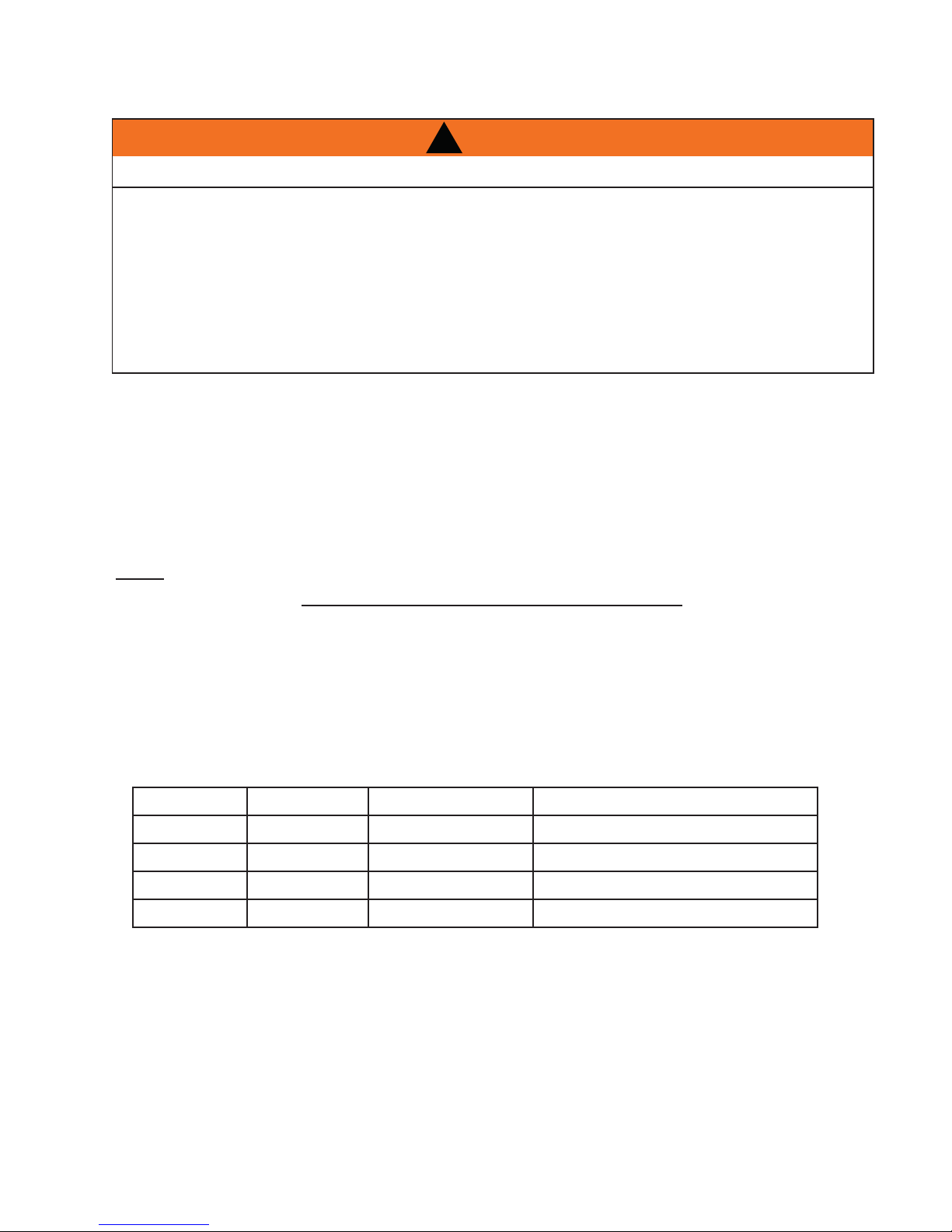
SAFETY INFORMATION
!
WARNING
If the information in these instructions are
not followed exactly, a fi re or explosion
may result causing property damage,
personal injury or loss of life.
- Do not store or use gasoline or other fl ammable
vapors and liquids in the vicinity of this or any
other appliance.
- WHAT TO DO IF YOU SMELL GAS:
• Do not try to light any appliance.
• Do not touch any electrical switch; do not use
any phone in your building.
• Immediately call your gas supplier from a
neighbour’s phone. Follow the gas supplier’s
instructions.
• If you cannot reach your gas supplier, call the
fi re department.
- Installation and service must be performed by a
qualifi ed installer, service agency or the supplier.
CERTIFIED
Wolf Steel Ltd., 24 Napoleon Rd., Barrie, ON, L4M 4Y8 Canada /
Phone (705)721-1212 • Fax (705)722-6031 • www.napoleonfi replaces.com • ask@napoleon.on.ca
$10.00
103 Miller Drive, Crittenden, Kentucky, USA, 41030
1.1
W415-0820 / B / 10.23.09
Page 2

2
TABLE OF CONTENTS
1.0 INSTALLATION OVERVIEW 3
1.1 USING NON-COMBUSTIBLE MATERIAL 3
1.2 USING COMBUSTIBLE MATERIAL 4
2.0 INTRODUCTION 5
2.1 DIMENSIONS 6
2.2 GENERAL INSTRUCTIONS 7
2.3 GENERAL INFORMATION 8
2.4 RATING PLATE INFORMATION 9
2.5 CARE OF GLASS 9
2.6 CARE OF PLATED PARTS 9
3.0 VENTING 10
3.1 VENTING LENGTHS AND COMPONENTS 10
3.2 TYPICAL VENT INSTALLATIONS 11
3.3 SPECIAL VENT INSTALLATIONS 12
3.3.1 PERISCOPE TERMINATION 12
3.3.2 CORNER TERMINATION 12
3.4 VENT TERMINAL CLEARANCES 13
3.5 VENT APPLICATION FLOW CHART 14
3.6 DEFINITIONS 14
3.7 ELBOW VENT LENGTHS 14
3.8 HORIZONTAL TERMINATION 15
3.9 VERTICAL TERMINATION 17
4.0 INSTALLATION 19
4.1 WALL AND CEILING PROTECTION 19
4.1.1 HORIZONTAL INSTALLATION 20
4.1.2 VERTICAL INSTALLATION 20
4.2 USING FLEXIBLE VENT COMPONENTS 21
4.2.1 HORIZONTAL AIR TERMINAL INSTALLATION 21
4.2.2 VERTICAL AIR TERMINAL INSTALLATION 22
4.3 USING RIGID VENT COMPONENTS 23
4.3.1 HORIZONTAL AIR TERMINAL INSTALLATION 23
4.3.2 EXTENDED HORIZONTAL AIR TERMINAL INSTALLATION 23
4.3.3 VERTICAL VENTING INSTALLATION 24
4.4 MOBILE HOME 25
4.5 ACCESS PANEL FOR GAS LINE CONNECTION 25
4.6 GAS INSTALLATION 26
5.0 FRAMING 27
5.1 MINIMUM CLEARANCE TO COMBUSTIBLES 29
5.2 MINIMUM CLEARANCE TO COMBUSTIBLE ENCLOSURES 30
5.3 MINIMUM MANTEL CLEARANCES 32
6.0 FINISHING 33
6.1 DOOR REMOVAL / INSTALLATION 33
6.2 DOOR GLASS REPLACEMENT 34
6.3 LOG PLACEMENT 35
6.4 GLOWING EMBER PLACEMENT 37
6.5 CHARCOAL EMBERS 37
6.6 OPTIONAL VERMICULITE 37
6.7 OPTIONAL CHARCOAL LUMPS (STANDARD ON HD46) 37
6.8 LOGO PLACEMENT 37
7.0 OPTIONAL BLOWER INSTALLATION 38
7.1 ACCESSING THE BLOWER 38
7.2 INSTALLING THE BLOWER 39
7.3 INSTALLING THE BLOWER 39
8.0 WIRING DIAGRAM / ELECTRICAL INFORMATION 40
8.1 WIRING REQUIREMENTS 40
8.2 OPTIONAL ACCESSORIES REQUIREMENTS 40
8.3 JUNCTION BOX INSTALLATION 41
8.4 WIRING DIAGRAM 42
9.0 OPERATION 43
10.0 ADJUSTMENT 44
10.1 PRESSURE ADJUSTMENT 44
10.2 VENTURI ADJUSTMENT 44
10.3 FLAME ADJUSTMENT 44
10.4 FLAME CHARACTERISTICS 45
11.0 MAINTENANCE 45
12.0 REPLACEMENT PARTS 46
13.0 TROUBLESHOOTING 49
14.0 WARRANTY 51
15.0 SERVICE HISTORY 52
NOTE: Changes, other than editorial, are denoted by a vertical line in the margin.
W415-0820 / B / 10.23.09
Page 3
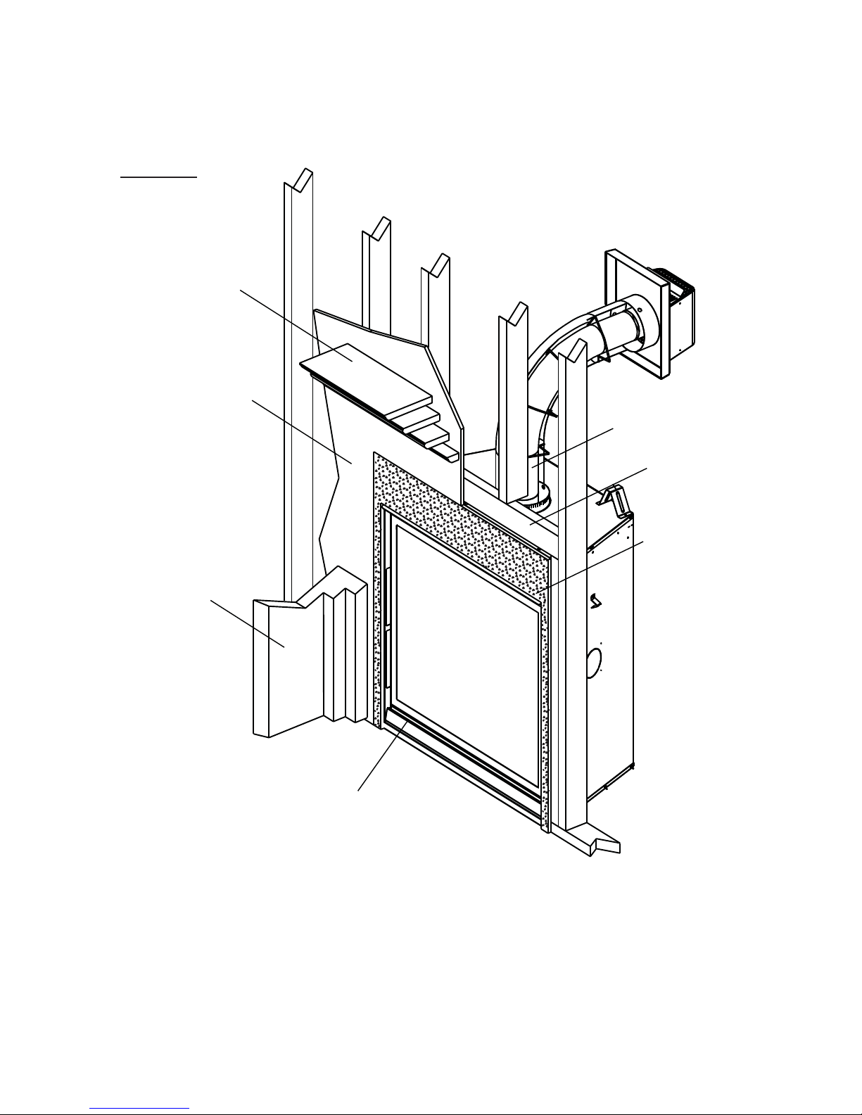
1.0 INSTALLATION OVERVIEW
1.1 USING NON-COMBUSTIBLE MATERIAL
FIGURE 1.1
Mantel, see “MINIMUM
MANTEL CLEARANCES” section.
Enclosures, see the
section “MINIMUM
CLEARANCES TO
COMBUSTIBLE
ENCLOSURES”
section for drywall (or
other combustible
material).
3
Venting, see “VENTING”
section.
Framing, see “FRAMING”
section.
Framing, see
“FRAMING”
section.
Enclosures, see the
section “MINIMUM
CLEARANCE TO COMBUSTIBLE ENCLOSURES” section for
non-combustible materials
such as tile, marble,
granite, etc.
Side
Wall
Rating plate, see “RATING
PLATE INFORMATION”
section.
W415-0820 / B / 10.23.09
Page 4
4
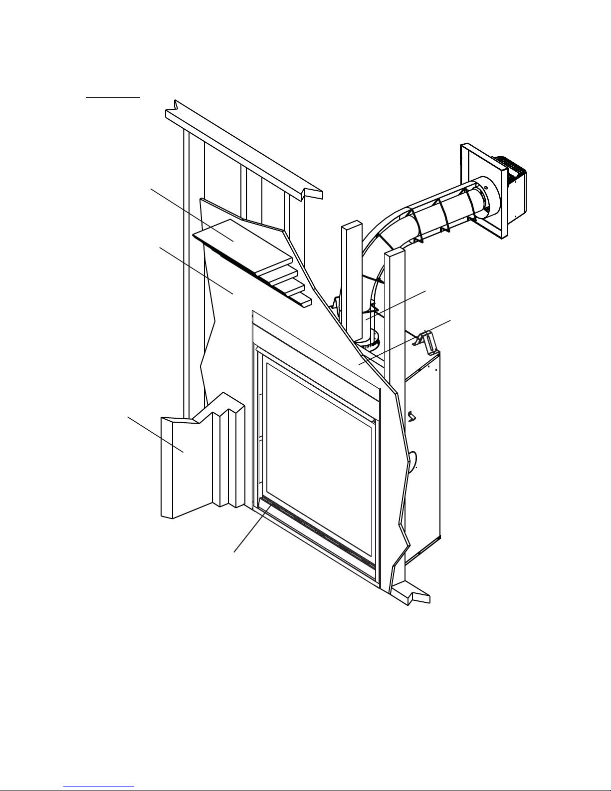
1.2 USING COMBUSTIBLE MATERIAL
FIGURE 1.2
Mantel, see “MINIMUM MANTEL
CLEARANCES”
section.
Enclosures, see “MINIMUM
CLEARANCE TO COMBUSTIBLE ENCLOSURES” for drywall (or
other combustible material)” section.
Venting, see “VENTING”
section.
Framing, see “FRAMING”
section.
Framing, see
“FRAMING”
section
Side
Wall
Rating plate, see “RATING
PLATE INFORMATION”
section.
W415-0820 / B / 10.23.09
Page 5

2.0 INTRODUCTION
• THIS APPLIANCE IS HOT WHEN OPERATED AND CAN CAUSE SEVERE BURNS IF CONTACTED.
• Do not operate appliance before reading and understanding operating instructions. Failure to operate
appliance according to operating instructions could cause fi re or injury.
• Risk of fi re or asphyxiation do not operate appliance with fi xed glass removed.
• Do not connect 110 volts to the control valve.
• Risk of burns. The appliance should be turned off and cooled before servicing.
• Do not install damaged, incomplete or substitute components.
• Risk of cuts and abrasions. Wear protective gloves and safety glasses during installation. Sheet metal
edges may be sharp.
• Do not burn wood or other materials in this appliance.
• Young children should be carefully supervised when they are in the same room as the appliance. Toddlers, young children and others may be susceptible to accidental contact burns. A physical barrier is
recommended if there are at risk individuals in the house. To restrict access to an appliance or stove,
install an adjustable safety gate to keep toddlers, young children and other at risk individuals out of the
room and away from hot surfaces.
• Clothing or other fl ammable material should not be placed on or near the appliance.
• Due to high temperatures, the appliance should be located out of traffi c and away from furniture and
draperies.
• Ensure you have incorporated adequate safety measure to protect infants/toddlers from touching hot
surfaces.
• Even after the appliance is out, the glass and/or screen will remain hot for an extended period of time.
• Check with your local hearth specialty dealer for safety screens and hearth guards to protect children
from hot surfaces. These screens and guards must be fastened to the fl oor.
• Any safety screen or guard removed for servicing must be replaced prior to operating the appliance.
• It is imperative that the control compartments, burners and circulating blower and its passageway in the
appliance and venting system are kept clean. The appliance and its venting system should be inspected
before use and at least annually by a qualifi ed service person. More frequent cleaning may be required
due to excessive lint from carpeting, bedding material, etc. The appliance area must be kept clear and
free from combustible materials, gasoline and other fl ammable vapors and liquids.
• Under no circumstances should this appliance be modifi ed.
• This appliance must not be connected to a chimney fl ue pipe serving a separate solid fuel burning appli-
ance.
• Do not use this appliance if any part has been under water. Immediately call a qualifi ed service techni-
cian to inspect the appliance and to replace any part of the control system and any gas control which
has been under water.
• Do not operate the appliance with the glass door removed, cracked or broken. Replacement of the glass
should be done by a licensed or qualifi ed service person.
• Do not strike or slam shut the appliance glass door.
• This appliance uses and requires a fast acting thermocouple. Replace only with a fast acting thermocouple supplied by Wolf Steel Ltd.
• Pressure relief doors must be kept closed while the appliance is operating to prevent exhaust fumes
containing carbon monoxide, from entering into the home. Temperatures of the exhaust escaping
through these openings can also cause the surrounding combustible materials to overheat and catch
fi re.
• Only doors / optional fronts certifi ed with the unit are to be installed on the appliance.
• Keep the packaging material out of reach of children and dispose of the material in a safe manner. As
with all plastic bags, these are not toys and should be kept away from children and infants.
• As with any combustion appliance, we recommend having your appliance regularly inspected and serviced as well as having a Carbon Monoxide Detector installed in the same area to defend you and your
family against Carbon Monoxide.
!
WARNING
5
3.1
W415-0820 / B / 10.23.09
Page 6
6
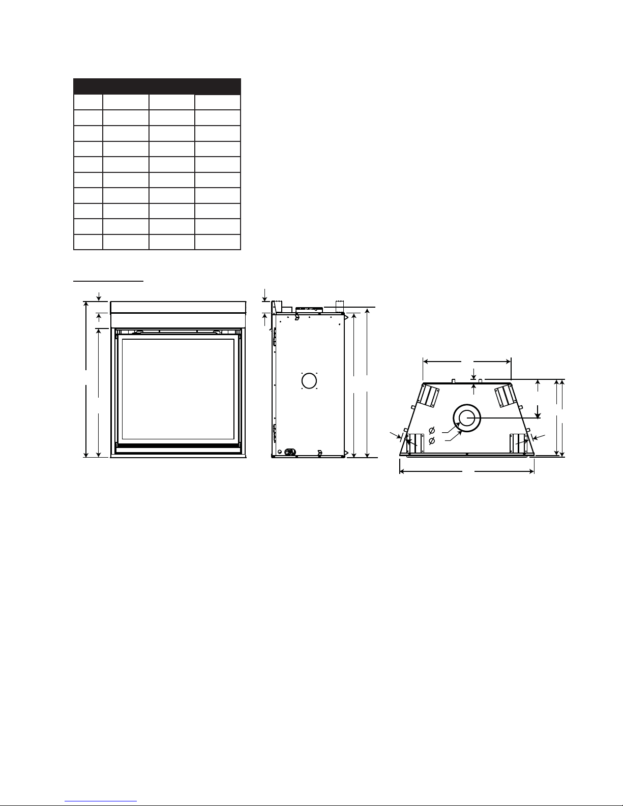
2.1 DIMENSIONS
REF HD35 HD40 HD46
A 41” 41” 41”
B 3” 3” 3”
C 39 1/4” 39 1/4” 39 1/4”
D 38” 38” 38”
E 10 3/16” 10 3/16” 10 3/16”
F 35 1/4” 40 1/4” 46 1/4”
G 23” 28” 34”
H 20” 20” 20”
I 20 1/2” 20 1/2” 20 1/2”
J 33 3/4” 33 3/4” 33 3/4”
FIGURE 2.1a-c
B
A
J
B
G
1"
C
D
E
H
I
2"
4"
7"
F
2"
W415-0820 / B / 10.23.09
Page 7

A
A
2.2 GENERAL INSTRUCTIONS
ALWAYS LIGHT THE PILOT WHETHER FOR THE FIRST TIME OR IF THE GAS SUPPLY HAS RAN OUT,
WITH THE GLASS DOOR OPENED OR REMOVED.
PROVIDE ADEQUATE CLEARANCE FOR SERVICING AND OPERATING THE APPLIANCE.
NEVER OBSTRUCT THE FRONT OPENING OF THE APPLIANCE.
OBJECTS PLACED IN FRONT OF THE APPLIANCE MUST BE KEPT A MINIMUM OF 48” FROM THE
HIGH PRESSURE WILL DAMAGE VALVE. DISCONNECT GAS SUPPLY PIPING BEFORE PRESSURE TESTING
GAS LINE AT TEST PRESSURES ABOVE 1/2 PSIG. CLOSE THE MANUAL SHUT-OFF VALVE BEFORE
PRESSURE TESTING GAS LINE AT TEST PRESSURES EQUAL TO OR LESS THAN 1/2 PSIG.
!
WARNING
PROVIDE ADEQUATE VENTILATION.
FRONT FACE OF THE UNIT.
FIRE RISK. EXPLOSION HAZARD.
7
USE ONLY WOLF STEEL APPROVED OPTIONAL ACCESSORIES AND REPLACEMENT PARTS WITH THIS APPLIANCE.
USING NON-LISTED ACCESSORIES (BLOWERS, DOORS, LOUVRES, TRIMS, GAS COMPONENTS, VENTING
COMPONENTS, ETC.) COULD RESULT IN A SAFETY HAZARD AND WILL VOID THE WARRANTY AND CERTIFICATION.
THIS GAS APPLIANCE SHOULD BE INSTALLED AND SERVICED BY A QUALIFIED INSTALLER to
conform with local codes. Installation practices vary from region to region and it is important to know the
specifi cs that apply to your area, for example in Massachusetts State:
• This product must be installed by a licensed plumber or gas fi tter when installed within the commonwealth
of Massachusetts.
• The appliance damper must be removed or welded in the open position prior to installation of a appliance
insert or gas log.
• The appliance off valve must be a “T” handle gas cock.
• The fl exible connector must not be longer than 36 inches.
• A Carbon Monoxide detector is required in all rooms containing gas fi red appliances.
• The appliance is not approved for installation in a bedroom or bathroom unless the unit is a direct vent
sealed combustion product.
The installation must conform with local codes or, in
absence of local codes, the National Gas and Propane
Installation Code CSA B149.1 in Canada, or the National
Fuel Gas Code, ANSI Z223.1 / NFPA 54 in the United
States. Suitable for mobile home installation if installed in
accordance with the current standard CAN/CSA Z240MH
Series, for gas equipped mobile homes, in Canada or
NSI Z223.1 and NFPA 54 in the United States.
s long as the required clearance to combustibles is
maintained, the most desirable and benefi cial location for an appliance is in the center of a building, thereby
allowing the most effi cient use of the heat created. The location of windows, doors and the traffi c fl ow in the
room where the appliance is to be located should be considered. If possible, you should choose a location
where the vent will pass through the house without cutting a fl oor or roof joist.
If the appliance is installed directly on carpeting, vinyl tile or other combustible material other than wood
fl ooring, the appliance shall be installed on a metal or wood panel extending the full width and depth.
www.ncertied.org
We suggest that our gas
hearth products be installed
and serviced by professionals
who are certied in the U.S.
by the National Fireplace
®
Institute
(NFI) as NFI Gas
Specialists
W415-0820 / B / 10.23.09
Page 8
8
If the optional fan or blower is installed, the junction box must be electrically connected and grounded in
accordance with local codes, use the current CSA C22.1 Canadian Electrical Code in Canada or the ANSI/
NFPA 70 National Electrical code in the United States.
This appliance is equipped with a power back up control system. Two 1.5 volt “D” batteries (not supplied) are
required for the battery pack included in the system. Use Alkaline batteries only.
2.3 GENERAL INFORMATION
FOR YOUR SATISFACTION, THIS APPLIANCE HAS BEEN TEST-FIRED TO ASSURE ITS OPERATION
AND QUALITY!
This appliance is approved for bathroom, bedroom and bed-sitting room installations and is suitable for mobile
home installations.
These appliances are equipped with tempered glass. Replacement glass must be obtained from your authorized dealer / distributor and is identifi ed in the replacement parts list. Do not substitute materials.
This appliance is not convertible for use with other gases, unless a certifi ed kit is used.
Expansion / contraction noises during heating up and cooling down cycles are normal and are to be expected.
Changes in fl ame appearance from “HI” to “LO” is more evident in natural gas than in propane.
4.1
Use only accessories designed for and listed with your specifi c appliance.
High Elevations
Input ratings are shown in Btu per hour and are certifi ed without de-rating up to 4,500 feet above sea level. For
Installations at the elevations above 4,500 feet and in the absence of specifi c recommendations from the local
authority having jurisdiction, the high altitude input rating shall be reduced at the rate of 4% for each additional
1,000 feet.
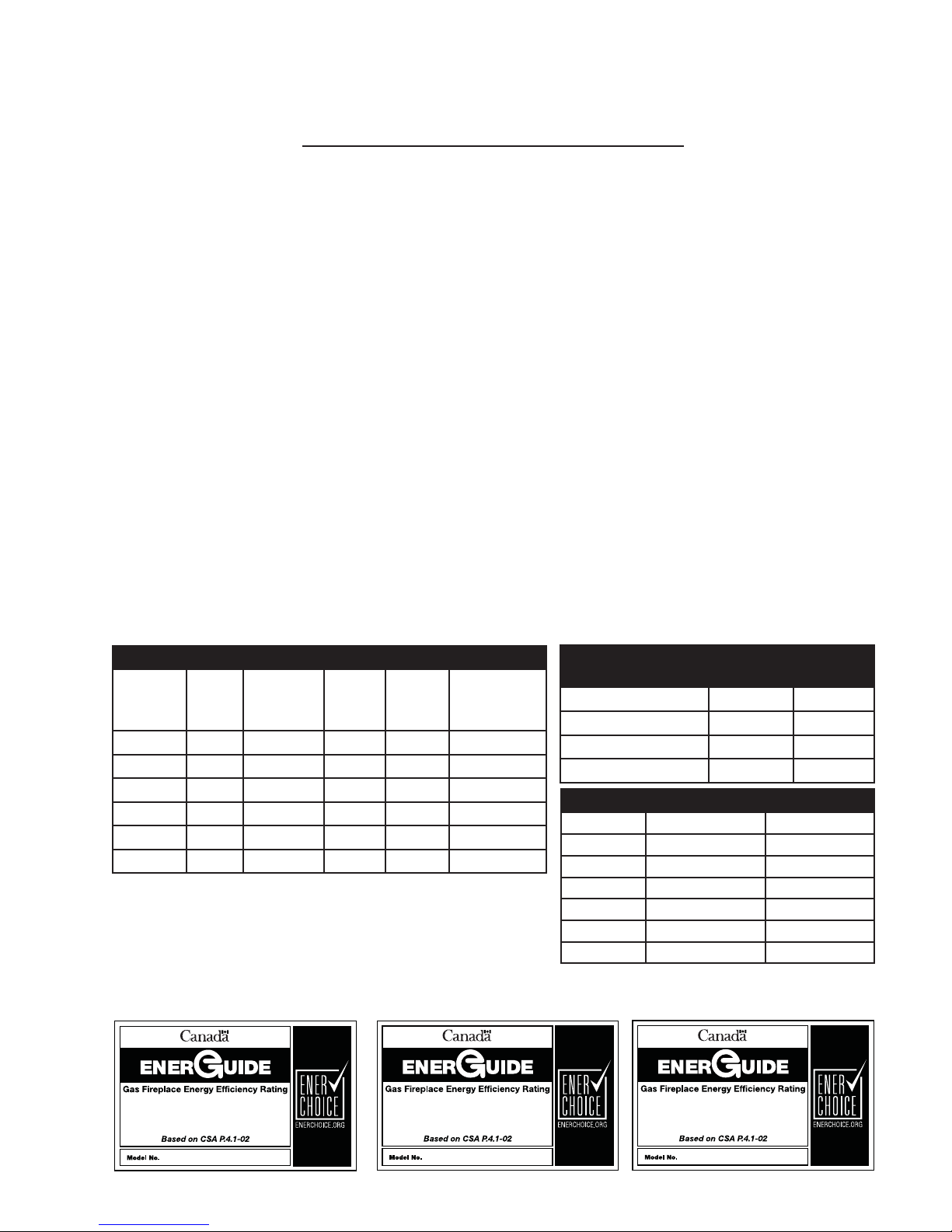
GAS SPECIFICATIONS
Model Fuel Gas
Control
HD35NT Nat IPI Hi/Lo 25,000 17,500 1/8” Open
HD35PT Prop* IPI Hi/Lo 25,000 17,500 5/16” Open
HD40NT Nat IPI Hi/Lo 27,000 18,900 1/8” Open
HD40PT Prop* IPI Hi/Lo 27,000 18,900 3/8” Open
HD46NT Nat IPI Hi/Lo 30,000 21,000 1/8” Open
HD46PT Prop* IPI Hi/Lo 30,000 21,000 3/8” Open
IPI - Intermittent Pilot Ignition System
* Using conversion kit
** Maximum Values
Conversions must be made by a qualifi ed service
technician using Wolf Steel specifi ed and approved parts.
Max.
Input
BTU/h
Min.
Input
BTU/h
Air shutter
setting
Minimum Inlet 4.5” w.c. 11.0” w.c.
Maximum Inlet 7.0” w.c. 13.0” w.c.
Manifold Pressure 3.5” w.c. 10.0” w.c.
GAS INLET AND MANIFOLD
PRESSURES
Natural Propane
EFFICIENCY RATINGS
Model Steady State(%) AFUE%**
HD35NT 82.1% 77.2%
HD35PT 82.1% 77.2%
HD40NT 80.5% 76.3%
HD40PT 80.5% 76.3%
HD46NT 82.9% 79.2%
HD46PT 82.9% 79.2%
63.3%
HD35
W415-0820 / B / 10.23.09
64.3%
HD40
65.1%
HD46
Page 9

2.4 RATING PLATE INFORMATION
9
CERTIFIED UNDER / HOMOLOGUÉ SELON LES NORMES: CSA 2.33-2009, ANSI Z21.88-2009 VENTED GAS FIREPLACE HEATER / APPAREIL DE CHAUFFAGE À GAZ VENTILÉS.
DIRECT VENT GAS FIREPLACE HEATER. SUITABLE FOR BEDROOM, BATHROOM AND
BED-SITTING ROOM INSTALLATION. SUITABLE FOR MOBILE HOME INSTALLATION
IF INSTALLED IN ACCORDANCE WITH THE CURRENT STANDARD CAN/CSA
Z240MH SERIES GAS EQUIPPED MOBILE HOMES, IN CANADA OR IN THE UNITED
STATES THE MANUFACTURED HOME CONTRUCTION AND SAFETY STANDARD,
TITLE 24 CFR, PART 3280. WHEN THIS US STANDARD IS NOT APPLICABLE
USE THE STANDARD FOR FIRE SAFETY CRITERIA FOR MANUFACTURED
HOME INSTALLATIONS, SITES AND COMMUNITIES, ANSI / NFPA 501A. WHEN
INSTALLED WITH SCREEN KIT GD-565KT, THE FIREPLACE COMPLIES WITH
CGA CERTIFICATION REQUIREMENT CR95-006.
HD46NT
Natural Gas/Gaz Naturel
PRESSION AU COLLECTEUR: 3.5" D'UNE COLONNE D'EAU
PRESSION D'ALIMENTATION MINIMALE: 4.5" D'UNE COLONNE D'EAU
PRESSION D'ALIMENTATION MAXIMALE: 7.0" D'UNE COLONNE D'EAU
MINIMUM SUPPLY PRESSURE: 4.5" WATER COLUMN
MAXIMUM SUPPLY PRESSURE: 7.0" WATER COLUMN
CHD46NT
0-4500 FT (0-1370m)
30,000 BTU/h
21,000 BTU/h
MANIFOLD PRESSURE: 3.5" WATER COLUMN
#38
CERTIFIED
CERTIFIED FOR
CERTIFIEE POUR
REDUCED INPUT / ALIMENTATION REDUITE
CANADA USA
REFERENCE # 161746
MODEL
ALTITUDE / ELEVATION
INPUT / ALIMENTATION
ORIFICE / INJECTEUR
AFUE: 67.7% AFUE: 67.7%
THIS VENTED GAS FIREPLACE HEATER IS NOT FOR USE WITH
AIR FILTERS AND NOT FOR USE WITH SOLID FUEL. FOR USE
WITH GLASS DOORS CERTIFIED WITH THIS UNIT ONLY
WARNING: DO NOTADD ANY MATERIAL TO THEAPPLIANCE, WHICH WILL COME IN
CONTACT WITHTHE FLAMES, OTHER THAN THAT SUPPLIED BY THE MANUFACTURER
WITH THE APPLIANCE.
MINIMUM CLEARANCE TO COMBUSTIBLE MATERIALS /
DEGAGEMENTS MINIMAUX DES MATERIAUX COMBUSTIBLES:
TOP/ DESSUS 0 RECESSED DEPTH / PROFONDEUR D'ENCASTRE 20½"
FLOOR / PLANCHER 0 VENT SIDES / COTES DE L'EVENT 1"
SIDES / COTES 0 VENT TOP / DESSUS DE L’ÉVENT 2"
BACK / ARRIERE 0 VENT BOTTOM / DESSOUS DE L’ÉVENT 1"
MANTLE / MANTEAU 13"*
* MAXIMUM HORIZONTAL EXTENSION / EXTENSION HORIZONTALE MAXIMALE: 2".
SEE INSTRUCTION MANUAL FOR GREATER EXTENSIONS. SE RÉFÉRER AU
MANUEL D'INSTRUCTION POUR DES EXTENSIONS PLUS GRANDES.
SEE OWNER'S INSTRUCTION MANUAL FOR MINIMUM AND MAXIMUM VENT LENGTHS.
SE RÉFÉRER AU MANUEL D'INSTALLATION DU PROPRIÉTAIRE POUR LES LONGUEURS
D'EVACUATION MINIMALE ET MAXIMALE.
WOLF STEEL LTD, BARRIE, ON, CANADA
APPAREIL DE CHAUFFAGE À ÉVACUATION DIRECTE. HOMOLOGUÉ POUR INSTALLATION
DANS UNE CHAMBRE À COUCHER, UNE SALLE DE BAIN ET UN STUDIO. APPROPRIÉ
POUR INSTALLATION DANS UNE MAISON MOBILE SI SON INSTALLATION EST
CONFORME AUX EXIGENCES DE LA NORME CAN/CSA Z240MH SÉRIE DE MAISONS
MOBILES ÉQUIPÉES AU GAZ, EN VIGUEUR AU CANADA, OU AUX ÉTATS-UNIS, SELON
LA NORME DE SÉCURITÉ ET DE CONSTRUCTION DE MAISONS MANUFACTURÉES,
TITRE 24 CFR, SECTION 3280. DANS LE CAS OÙ CETTE NORME DES ÉTATS-UNIS NE
PEUT ÊTRE APPLIQUÉE, SE RÉFÉRER À LA NORME RELATIVE AU CRITÈRE DE
MESURES DE SÉCURITÉ CONTRE L'INCENDIE POUR LES INSTALLATIONS DANS LES
MAISONS MANUFACTURÉES, LES SITES ET LES COMMUNAUTÉS, ANSI/NFPA 501A.
LORSQU'IL EST INSTALLÉ AVEC LE PARE-ÉTINCELLES GD-565KT, LE FOYER EST
MANIFOLD PRESSURE: 10" WATER COLUMN
PRESSION AU COLLECTEUR: 10" D'UNE COLONNE D'EAU
MINIMUM SUPPLY PRESSURE: 11" WATER COLUMN
PRESSION D'ALIMENTATION MINIMALE: 11" D'UNE COLONNE D'EAU
MAXIMUM SUPPLY PRESSURE: 13" WATER COLUMN
PRESSION D'ALIMENTATION MAXIMALE: 13" D'UNE COLONNE D'EAU
CONFORME À LA NORME DE CERTIFICATION DE L'ACG CR95-006.
HD46PT
0-4500FT (0-1370m)
30,000 BTU/h
21,000 BTU/h
#52
Propane
CHD46PT
CE FOYER À GAZ VENTILÉS NE DOIT PAS ÊTRE UTILISÉ AVEC
DES FILTRES À AIR ET NE DOIT PAS ÊTRE UTILISÉ AVEC
UN COMBUSTIBLE SOLIDE. UTILISER AVEC LES PORTES
VITRÉES HOMOLOGUÉES AVEC CETTE UNITÉ SEULEMENT.
AVERTISSEMENT: N'A JOUTEZ PAS A CETAPPAREIL AUCUN MATERIAU DEVANT
ENTRER EN CONTACT AVEC LESFLAMMES AUTRE QUECELUI QUI EST FOURNIAVEC CET
APPAREIL PAR LE FABRICANT.
THE APPLIANCE MUSTBE VENTED USINGTHE APPROPRIATE WOLF STEEL VENT KITS. SEE OWNERS
INSTALLATIONMANUAL FORVENTING SPECIFICS.PROPER REINSTALLATION AND RESEALING IS
NECESSARY AFTER SERVICING THE VENT-AIR INTAKE SYSTEM.
GAZ EN UTILISANT L'ENSEMBLE D'ÉVACUATION PROPRE À
D'INSTALLATION DU PROPRIÉTAIRE POUR LES SPÉCIFICATIONS DE L'ÉVACUATION. IL EST IMPORTANT
DE BIEN RÉINSTALLERET RESCELLER L'ÉVENT APRÈS AVOIR EFFECTUÉ LE SERVICE DU SYSTÊME DE PRISE D'AIR.
ELECTRICAL RATING / CLASSIFICATION: 115V, 60HZ, LESS THAN 12 AMPS.
SPÉCIFICATIONS ÉLECTRIQUES : 115 V, 60 HZ, MOINS DE 12 A.
OPTIONAL FAN KIT / SOUFFLERIE OPTIONNELLE : GZ550-KT, GD65
MADE IN CANADA / FABRIQUE AU CANADA
SERIAL NUMBER/NO. DE SERIE: HD46
L'APPAREIL DOIT ÉVACUER SE S
WOLF
STEEL. SE RÉFÉRER
AU MANUEL
W385-0454 / A
INSTALLER: It is your responsibility to check off the appropriate box on the rating plate according to
the model, venting and gas type of the appliance.
For rating plate location, see “INSTALLATION OVERVIEW” section.
2.5 CARE OF GLASS
DO NOT CLEAN GLASS WHEN HOT! DO NOT USE
ABRASIVE CLEANERS TO CLEAN GLASS.
Buff lightly with a clean dry soft cloth. Clean both sides
of the glass after the fi rst 10 hours of operation with a
recommended fi replace glass cleaner. Thereafter clean
as required. If the glass is not kept clean permanent
discoloration and / or blemishes may result.
2.6 CARE OF PLATED PARTS
If the appliance is equipped with plated parts, you must clean fi ngerprints or other marks from the plated
surfaces before operating the appliance for the fi rst time. Use a glass cleaner or vinegar and towel to clean.
If not cleaned properly before operating for the fi rst time, the marks can cause permanent blemishes on
the plating. After the plating is cured, the fi ngerprints and oils will not affect the fi nish and little maintenance
is required, just wipe clean as needed. Prolonged high temperature burning with the door ajar may cause
discolouration on plated parts.
NOTE: The protective wrap on plated parts is best removed when the assembly is at room
temperature but this can be improved if the assembly is warmed, using a hair dryer or similar heat
source.
!
WARNING
HOT GLASS WILL
CAUSE BURNS.
DO NOT TOUCH GLASS
UNTIL COOLED.
NEVER ALLOW CHILDREN
TO TOUCH GLASS.
5.1
6.1
W415-0820 / B / 10.23.09
Page 10
10
3.0 VENTING
RISK OF FIRE, MAINTAIN SPECIFIED AIR SPACE CLEARANCES TO VENT PIPE AND APPLIANCE.
IF VENTING IS INCLUDED WITH SPACERS THE VENT SYSTEM MUST BE SUPPORTED EVERY 3 FEET
FOR BOTH VERTICAL AND HORIZONTAL RUNS. USE SUPPORTS OR EQUIVALENT
NON-COMBUSTIBLE STRAPPING TO MAINTAIN THE REQUIRED CLEARANCE FROM
COMBUSTIBLES. USE WOLF STEEL LTD. SUPPORT RING ASSEMBLY W010-0370 OR EQUIVALENT
NON-COMBUSTIBLE STRAPPING TO MAINTAIN THE MINIMUM CLEARANCE TO COMBUSTIBLES
FOR BOTH VERTICAL AND HORIZONTAL RUNS. SPACERS ARE ATTACHED TO THE INNER PIPE AT
PREDETERMINED INTERVALS TO MAINTAIN AN EVEN AIR GAP TO THE OUTER PIPE. THIS GAP IS
REQUIRED FOR SAFE OPERATION. A SPACER IS REQUIRED AT THE START, MIDDLE AND END OF
EACH ELBOW TO ENSURE THIS GAP IS MAINTAINED. THESE SPACERS MUST NOT BE REMOVED.
THIS APPLIANCE USES A 4” EXHAUST / 7” AIR INTAKE VENT PIPE SYSTEM.
For safe and proper operation of the appliance follow the venting instruction exactly. Deviation from the
minimum vertical vent length can create diffi culty in burner start-up and/or carboning. Under extreme vent
confi gurations, allow several minutes (5-15) for the fl ame to stabilize after ignition. Vent lengths that pass
through unheated spaces (attics, garages, crawl spaces) should be insulated with the insulation wrapped in
a protective sleeve to minimize condensation. Provide a means for visually checking the vent connection to
the appliance after the appliance is installed. Use a fi restop, vent pipe shield or attic insulation shield when
penetrating interior walls, fl oor or ceiling.
NOTE: If for any reason the vent air intake system is disassembled; reinstall per the instructions
provided for the initial installation.
!
WARNING
Refer to the section applicable to your installation.
7.1
3.1 VENTING LENGTHS AND COMPONENTS
Use only Wolf Steel, Simpson Dura-Vent, Selkirk Direct Temp, American Metal Amerivent or Metal-Fab venting
components. Minimum and maximum vent lengths, for both horizontal and vertical installations, and air terminal
locations for either system are set out in this manual and must be adhered to. For Simpson Dura-Vent, Selkirk Direct
Temp, American Metal Amerivent and Metal-Fab follow the installation procedure provided with the venting components.
A starter adaptor must be used with the following vent systems and may be purchased from the corresponding supplier:
PART 4”/7” SUPPLIER WEBSITE
Duravent W175-0053 Wolf Steel www.duravent.com
Amerivent 4DSC-N2 American Metal www.americanmetalproducts.com
Direct Temp 4DT-AAN Selkirk www.selkirkcorp.com
SuperSeal 4DNA Metal-Fab www.mtlfab.com
* For Simpson Dura-Vent, Selkirk Direct Temp, American Metal Amerivent and Metal-Fab follow the installation
procedure found on the website for your venting supplier.
For vent systems that provide seals on the inner exhaust fl ue, only the outer air intake joints must be sealed using a red
high temperature silicone (RTV). This same sealant may be used on both the inner exhaust and outer intake vent pipe
joints of all other approved vent systems except for the exhaust vent pipe connection to the appliance fl ue collar which must
be sealed using the black high temperature sealant Mill Pac. High temperature sealant must be ordered separately.
When using Wolf Steel venting components, use only approved Wolf Steel rigid / fl exible components with the following
termination kits: wall terminal kit GD222, GD222R, or 1/12 to 7/12 pitch roof terminal kit GD110, 8/12 to 12/12 roof terminal
kit GD 111, fl at roof terminal kit GD112 or periscope kit GD201 (for wall penetration below grade). With fl exible venting, in
conjunction with the various terminations, use either the 5 foot vent kit GD220 or the 10 foot vent kit GD330.
W415-0820 / B / 10.23.09
Page 11

For optimum flame appearance and appliance performance, keep the vent length and number of elbows to a minimum.
The air terminal must remain unobstructed at all times. Examine the air terminal at least once a year to verify that
it is unobstructed and undamaged.
Rigid and fl exible venting systems must not be combined. Different venting manufacturer components must not
be combined.
These vent kits allow for either horizontal or vertical venting of the appliance. The maximum allowable horizontal run is 20
feet. The maximum allowable vertical vent length is 40 feet. The maximum number of vent connections is two horizontally
or three vertically (excluding the appliance and the air terminal connections) when using fl exible venting.
Horizontal runs may have a 0” rise per foot however for optimum performance it is recommended that all horizontal runs have a minimum 1/4” rise per foot using fl exible or rigid venting. For safe and proper operation of
the appliance, follow the venting instructions exactly.
When terminating vertically, the vertical rise is a minimum 3 feet and a maximum 40 feet from the top of the
appliance.
3.2 TYPICAL VENT INSTALLATIONS
11
8.1
16” MIN
FIGURE 3.2
19 1/2” MIN
38”
24” MAX
57 1/2”
MIN
PLUS
RISE*
FIGURE 3.2
40FT
MAX
3FT
MIN
38”
* See “VENTING” section.
W415-0820 / B / 10.23.09
Page 12
12
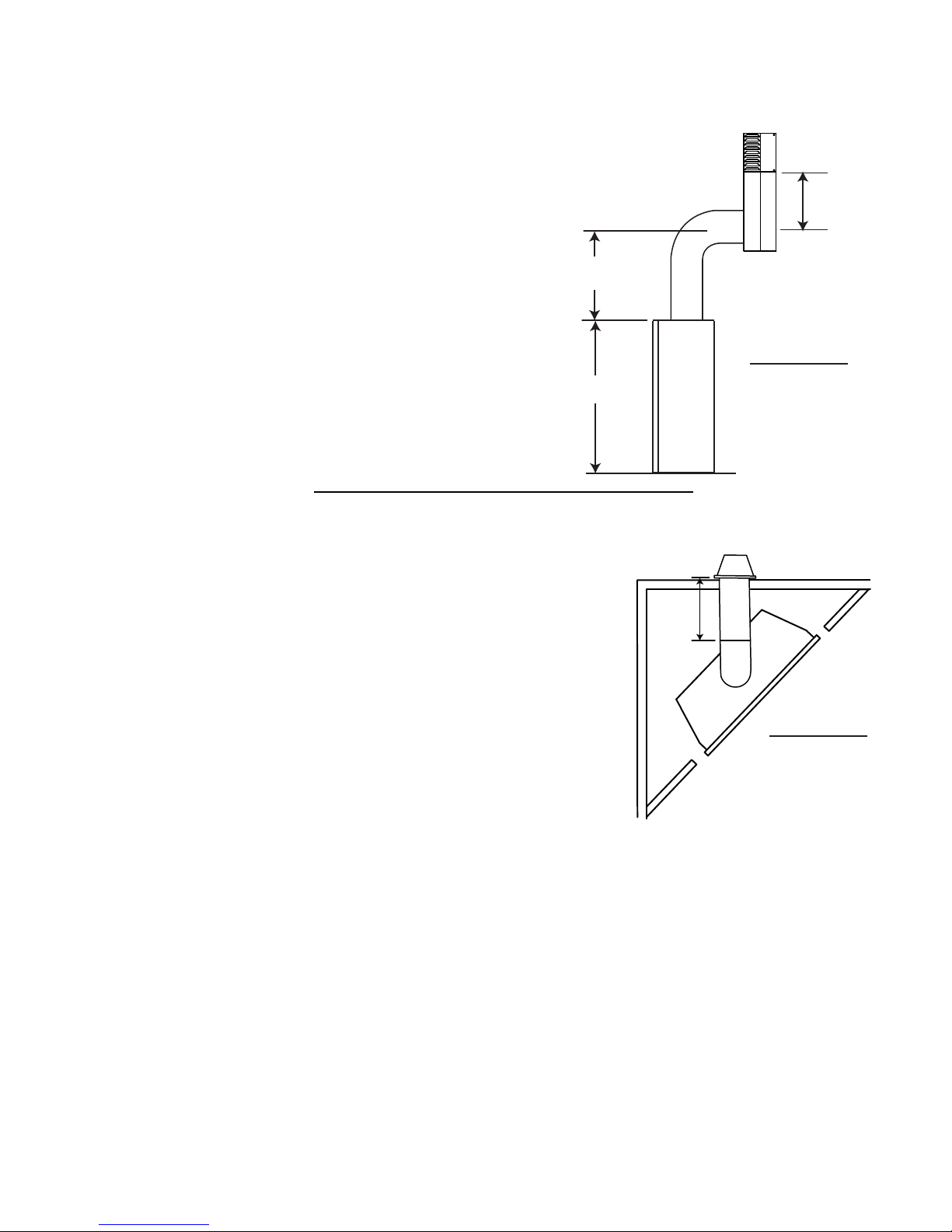
3.3 SPECIAL VENT INSTALLATIONS
3.3.1 PERISCOPE TERMINATION
Use the periscope kit to locate the air termination above grade. The periscope must
be installed so that when fi nal grading is completed, the bottom air slot is located a
minimum 12” above grade. The maximum allowable vent length is 10’.
12” MIN TO
GRADE
30” MIN
FIGURE 3.3.1
38”
9.1
3.3.2 CORNER TERMINATION
The maximum vent length for a corner installation is 20” of horizontal run
with a minimum 19 1/2” rise.
20”
MAX
FIGURE 3.3.2
W415-0820 / B / 10.23.09
Page 13

3.4 VENT TERMINAL CLEARANCES
FIGURE 3.4
INSTALLATIONS
CANADA U.S.A.
A 12” 12” Clearance above grade, veranda porch, deck or balcony.
B 12” 9” Clearance to windows or doors that open.
C 12” * 12” * Clearance to permanently closed windows.
D 18” ** 18” **
E 12” ** 12” ** Clearance to unventilated soffi t.
F 0” 0” Clearance to an outside corner wall.
G
0” *** 0” *** Clearance to an inside non-combustible corner wall or protruding non-combustible obstructions (chimney, etc.).
2” *** 2” *** Clearance to an inside combustible corner wall or protruding combustible obstructions (vent chase, etc.).
H 3’ 3’ ****
I 3’ 3’ **** Clearance to a service regulator vent outlet.
J 12” 9” Clearance to a non-mechanical air supply inlet to the building or a combustion air inlet to any other appliance.
K 6’ 3’ † Clearance to a mechanical air supply inlet.
L 7’ ‡ 7’ **** Clearance above a paved sidewalk or paved driveway located on public property.
M 12” †† 12” **** Clearance under a veranda, porch, deck or balcony.
N 16” 16” Clearance above the roof.
O 2’ †* 2’ †* Clearance from an adjacent wall including neighbouring buildings.
* Recommended to prevent condensation on windows and thermal breakage
** it is recommended to use a heat shield and to maximize the distance to vinyl clad soffi ts.
*** The periscope requires a minimum 18 inches clearance from an inside corner.
**** This is a recommended distance. For additional requirements check local codes.
† 3 feet above if within 10 feet horizontally.
‡ A vent shall not terminate directly above a sidewalk or paved driveway that is located between two single family dwellings and serves both dwellings.
†† Permitted only if the veranda, porch, or deck is fully open on a minimum of two sides beneath the fl oor.
†* Recommended to prevent recirculation of exhaust products. For additional requirements check local codes.
NOTE: Clearances are in accordance with local installation codes and the requirements of the gas supplier.
Vertical clearance to ventilated soffi ts located above the terminal within a horizontal distance of 2’ from
the centerline of the terminal.
Clearance to each side of the centerline extended above the meter / regulator assembly to a maximum
vertical distance of 15’.
13
12.1
W415-0820 / B / 10.23.09
Page 14
14
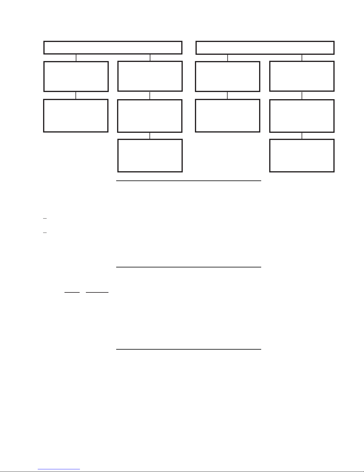
3.5 VENT APPLICATION FLOW CHART
Horizontal Termination
Vertical rise is equal
to or greater than
the horizontal run
Horizontal run +
vertical rise to
maximum of 40 feet
3.6 DEFINITIONS
For the following symbols used in the venting calculations and examples are:
> - greater than
> - equal to or greater than
< - less than
< - equal to or less than
HT - total of both horizontal vent lengths (Hr) and offsets (Ho) in feet
HR - combined horizontal vent lengths in feet
HO - offset factor: .03 (total degrees of offset - 90°*) in feet
VT - combined vertical vent lengths in feet
Vertical rise is less
than horizontal run
Horizontal run +
vertical rise to
maximum of 24.75
feet
4.2 times the
vertical rise equal to
or greater than the
horizontal run
Vertical Termination
Vertical rise is equal
to or greater than
the horizontal run
Horizontal run +
vertical rise to
maximum of 40 feet
Vertical rise is less
than horizontal run
Horizontal run +
vertical rise to
maximum of 40 feet
3 times the vertical
rise equal to or
greater than the
horizontal run
13.1
14.1
3.7 ELBOW VENT LENGTHS
FEET INCHES
1° 0.03 0.5
15° 0.45 6.0
30° 0.9 11.0
45° 1.35 16.0
90°* 2.7 32.0
* The fi rst 90° offset has a zero value and is shown in the formula as - 90°
15.1
W415-0820 / B / 10.23.09
Page 15

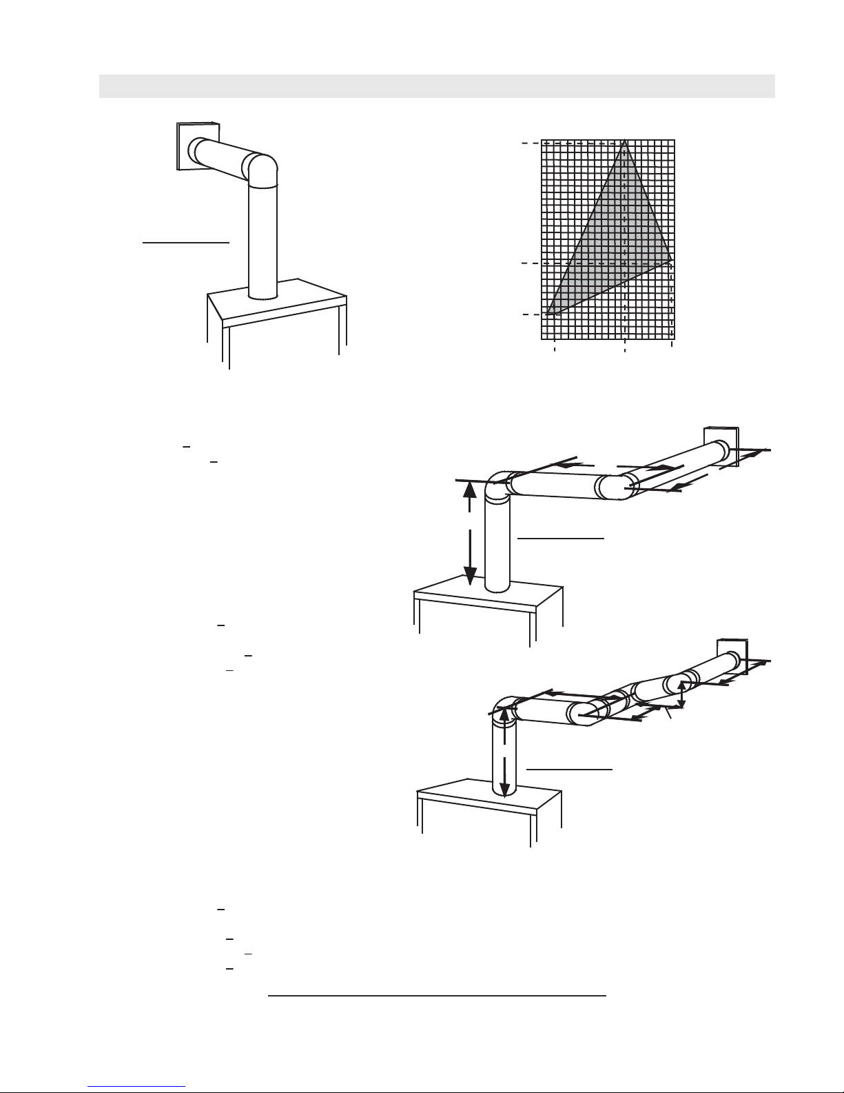
3.8 HORIZONTAL TERMINATION
15
(HT) < (VT)
Simple venting confi guration (only one 90° elbow)
FIGURE 3.8.1
REQUIRED
VERTICAL
See graph to determine the required vertical
for the required horizontal run HT.
rise V
T
40
39
30
20
RISE IN
FEET VT
10
0
2.5 5 7.5 10 12.5 15
HORIZONTAL VENT RUN PLUS OFFSET IN
FEET H
The shaded area within the lines represents
acceptable values for HT and V
For vent confi gurations requiring more than one 90° elbow, the following formulas apply:
Formula 1: HT < V
T
Formula 2: HT + VT < 40 feet
FIGURE 3.8.2
Example 1:
V1 = 3 FT
V2 = 8 FT
VT = V1 + V2= 3 FT + 8 FT = 11 FT
H1 = 2.5 FT
H2 = 2 FT
HR = H1 + H2 = 2.5 + 2 = 4.5 FT
HO = .03 (three 90° elbows - 90°) = .03 (270° - 90°) = 5.4 FT
90°
HT = HR + HO = 4.5 + 5.4 = 9.9 FT
HT + VT = 9.9 + 11 = 20.9 FT
90°
90°
17.5 20
T
T
H
2
V
2
H
1
Formula 1: HT < V
T
9.9 < 11
Formula 2: H
+ VT < 40 FT
T
20.9 < 40
Since both formulas are met, this vent confi guration is acceptable.
V
1
16.1
W415-0820 / B / 10.23.09
Page 16
16
V
V
V
V
(HT) > (VT)
Simple venting configuration (only one 90° elbow)
REQUIRED
See graph to determine the required vertical rise VT for the
required horizontal run H
150
147”
100
.
T
VERTICAL
FIGURE 3.8.3
RISE IN
INCHES V
T
57”
50
19 1/2”
0
515
2’
10
12.5’
19.5’
20
HORIZONTAL VENT RUN PLUS OFFSET IN FEET H
T
The shaded area within the lines represents acceptable
values for HT and VT
For vent configurations requiring more than one 90° elbow, the following formulas apply:
Formula 1: H
Formula 2: HT + V
Example 2:
= VT = 6 FT
1
H
= 3 FT
1
H
= 5 FT
2
H
= H
R
1
H
= .03 (two 90° elbows - 90°) = .03 (180° - 90°) = 2.7 FT
O
H
= H
T
R
H
+ V
T
T
< 4.2 V
T
+ H
= 3 + 5 = 8 FT
2
+ H
= 8 + 2.7 = 10.7 FT
O
= 10.7 + 6 = 16.7 FT
T
< 24.75 feet
T
90°
V
1
FIGURE 3.8.4
H
1
H
2
90°
Formula 1: HT < 4.2 V
4.2 VT = 4.2 x 6 = 25.2 FT
Formula 2: HT + V
16.7 < 24.75
Since both formulas are met, this vent configuration is acceptable.
Example 3:
= 4 FT
1
= 1.5 FT
2
= V
+ V
T
H
= 2 FT
1
H
= 1 FT
2
H
= 1 FT
3
H
= 1.5 FT
4
H
= H
R
H
= .03 (four 90° elbows - 90°) = .03 (360° - 90°) = 8.1 FT
O
H
= H
T
H
+ V
T
= 4 + 1.5 = 5.5 FT
1
2
+ H2 + H
1
+ H
R
= 13.6 + 5.5 = 19.1 FT
T
+ H4 = 2 + 1 + 1 + 1.5 = 5.5 FT
3
= 5.5 + 8.1 = 13.6 FT
O
Formula 1: HT < 4.2 V
4.2 VT = 4.2 x 5.5 = 23.1 FT
T
< 24.75 FT
T
T
90°
V
1
H
1
90°
FIGURE 3.8.5
90°
90°
H
V
2
H
H
2
3
4
13.6 < 23.1
Formula 2: HT + V
19.1 < 24.75
< 24.75 FT
T
Since both formulas are met, this vent configuration is acceptable.
16.1_2
W415-0820 / B / 10.23.09
Page 17

3.9 VERTICAL TERMINATION
17
(HT) < (VT)
Simple venting configurations.
See graph to determine the required vertical rise V
required horizontal run HT.
40
FIGURE 3.9.1
30
REQUIRED
VERTICAL
20
RISE IN
FEET V
T
10
3
0
HORIZONTAL VENT RUN PLUS OFFSET IN FEET H
The shaded area within the lines represents acceptable
values for HT and VT
For vent configurations requiring one or more 90° elbows the following formulas apply:
Formula 1: H
Formula 2: HT + V
< V
T
T
< 40 feet
T
for the
T
5101520
FIGURE 3.9.2
T
Example 6:
V
= 5 FT
1
V
= 6 FT
2
V
= 10 FT
3
V
= V
+ V2 + V3 = 5 + 6 + 10 = 21 FT
T
1
H
= 8 FT
1
H
= 2.5 FT
2
H
= H
+ H
R
H
= .03 (four 90° elbows - 90°)
O
= .03 (360° - 90°) = 8.1 FT
H
= H
T
H
+ V
T
Formula 1: HT < 3.5 V
18.6 < 21
Formula 2: HT + V
39.6 < 40
= 8 + 2.5 = 10.5 FT
1
2
+ H
= 10.5 + 8.1 = 18.6 FT
R
O
= 18.6 + 21 = 39.6 FT
T
T
< 40 FT
T
Since both formulas are met, this vent configuration is acceptable.
90°
V
3
90°
H
2
V
H
1
V
1
2
90°
90°
18.1
W415-0820 / B / 10.23.09
Page 18

18
(HT) > (VT)
Simple venting configurations.
See graph to determine the required vertical rise V
required horizontal run H
FIGURE 3.9.3
20
19
REQUIRED
VERTICAL
RISE IN
FEET V
For vent configurations requiring more than two 90° elbows the following formulas apply:
Formula 1: H
Formula 2: HT + V
< 3V
T
T
< 40 feet
T
Example 2:
V
= 2 FT
1
V
= 1 FT
2
V
= 1.5 FT
3
V
= V
+ V2 + V3 = 2 + 1 + 1.5 = 4.5 FT
T
1
H
= 6 FT
1
H
= 2 FT
2
H
= H
+ H
R
H
= .03 (four 90° elbows - 90°)
O
= .03 (360° - 90°) = 8.1 FT
H
= H
T
H
+ V
T
= 6 + 2 = 8 FT
1
2
+ H
= 8 + 8.1 = 16.1 FT
R
O
= 16.1 + 4.5 = 20.6 FT
T
10
T
3
0
5101520
HORIZONTAL VENT RUN PLUS OFFSET IN FEET H
The shaded area within the lines represents acceptable
values for H
FIGURE 3.9.4
90°
V
1
for the
T
25 30
T
and VT
T
.
T
90°
V
H
2
H
1
V
2
3
90°
90°
Formula 1: HT < 3V
3VT = 3 x 4.5 = 13.5 FT
T
16.1 < 13.5
Since this formula is not met, this vent configuration is unacceptable.
Formula 2: HT < VT = 40 feet
20.6 < 40
Since only formula 2 is met, this vent configuration is unacceptable and a new fireplace location or vent configuration will
need to be established to satisfy both formulas.
18.1_2
W415-0820 / B / 10.23.09
Page 19

4.0 INSTALLATION
FOLLOW THE VENTING INSTRUCTIONS EXACTLY.
ALL INNER EXHAUST AND OUTER INTAKE VENT PIPE JOINTS MAY BE SEALED USING EITHER RED
RTV HIGH TEMP SILICONE SEALANT W573-0002 (NOT SUPPLIED) OR BLACK HIGH TEMP MILL PAC
W573-0007 (NOT SUPPLIED) WITH THE EXCEPTION OF THE APPLIANCE EXHAUST FLUE COLLAR
WHICH MUST BE SEALED USING MILL PAC.
IF USING PIPE CLAMPS TO CONNECT VENT COMPONENTS, 3 SCREWS MUST ALSO BE USED TO
ENSURE THE CONNECTION CANNOT SLIP OFF.
RISK OF FIRE, EXPLOSION OR ASPHYXIATION. IMPROPER SUPPORT OF THE ENTIRE VENTING
SYSTEM MAY ALLOW VENT TO SAG AND SEPARATE. USE VENT RUN SUPPORTS AND CONNECT
VENT SECTIONS PER INSTALLATION INSTRUCTIONS.
RISK OF FIRE, DO NOT ALLOW LOOSE MATERIALS OR INSULATION TO TOUCH THE VENT PIPE.
REMOVE INSULATION TO ALLOW FOR THE INSTALLATION OF THE ATTIC SHIELD AND TO
MAINTAIN CLEARANCES TO COMBUSTIBLES.
!
WARNING
DO NOT CLAMP THE FLEXIBLE VENT PIPE.
19
4.1 WALL AND CEILING PROTECTION
!
DO NOT FILL THE SPACE BETWEEN THE VENT PIPE AND ENCLOSURE WITH ANY TYPE OF
MATERIAL. DO NOT PACK INSULATION OR COMBUSTIBLES BETWEEN CEILING FIRESTOPS.
ALWAYS MAINTAIN SPECIFIED CLEARANCES AROUND VENTING AND FIRESTOP SYSTEMS.
INSTALL WALL SHIELDS AND FIRESTOPS AS SPECIFIED. FAILURE TO KEEP INSULATION OR
OTHER MATERIALS AWAY FROM VENT PIPE MAY CAUSE FIRE.
For optimum performance it is recommended that all horizontal runs have a minimum of 1/4” rise per foot using
fl exible venting. For safe and proper operation of the appliance, follow the venting instructions exactly.
68.2
WARNING
70.1
W415-0820 / B / 10.23.09
Page 20

20
A
4.1.1 HORIZONTAL INSTALLATION
THE FIRESTOP ASSEMBLY MUST BE INSTALLED WITH THE VENT SHIELD TO THE TOP.
TERMINALS MUST NOT BE RECESSED INTO A WALL OR SIDING MORE THAN THE DEPTH OF THE
RETURN FLANGE OF THE MOUNTING PLATE.
This application occurs when venting through an exterior wall.
Having determined the correct height for the air terminal
location, cut and frame a hole in the exterior wall as
illustrated to accommodate the fi restop assembly.
Dry fi t the fi restop assembly before proceeding to
ensure the brackets on the rear surface fi t to the
inside surface of the horizontal framing.
The length of the vent shield may be cut shorter
for combustible walls that are less than 8 1/2” thick
but the vent shield must extend the full depth of the
combustible wall.
. Apply a bead of caulking (not supplied) around the corner edge of
the inside surface of the fi restop assembly, fi t the fi restop
assembly to the hole and secure using the 4 screws W570-0026
(supplied in your manual baggie).
B. Once the vent pipe is installed in its fi nal position, apply high temperature sealant W573-0007 (not
supplied) between the pipe and the fi restop.
!
WARNING
CAULKING
FIRESTOP
SPACER
VENT
SHIELD
11 3/8”
9 7/8”
DETERMINE
THE
CORRECT
HEIGHT
FINISHING
MATERIAL
FIGURE 4.1.1
20.2
4.1.2 VERTICAL INSTALLATION
This application occurs when venting through a roof. Installation kits for
various roof pitches are available from your authorized dealer / distributor. See
accessories to order specifi c kits required.
A. Determine the air terminal location, cut and frame a square opening as
illustrated in the ceiling and the roof to provide the minimum 1“ clearance
between the vent pipe and any combustible material. Try to center the vent
pipe location midway between two joists to prevent having to cut them. Use
a plumb bob to line up the center of the openings. A vent pipe shield will
prevent any materials such as insulation, from fi lling up the 1” air space
around the pipe. Nail headers between the joist for extra support.
B. Apply a bead of caulking (not supplied) to the framework or to the Wolf
Steel vent pipe shield plate or equivalent (in the case of a fi nished ceiling),
and secure over the opening in the ceiling. A fi restop must be placed on the
bottom of each framed opening in a roof or ceiling that the venting system passes
through. Apply a bead of caulking all around and place a fi restop spacer over
the vent shield to restrict cold air from being drawn into the room or around the
fi replace. Ensure that both spacer and shield maintain the required clearance to
combustibles. Once the vent pipe is installed in its fi nal position, apply sealant
between the pipe and the fi restop assembly.
C. In the attic, slide the vent pipe collar down to cover up the open end of the shield and tighten.
This will prevent any materials, such as insulation, from fi lling up the 1” air space around the
pipe.
FIGURE 4.1.2b
VENT PIPE
FIGURE 4.1.2c
21.1
FIGURE 4.1.2a
9 3/4”
FIRESTOP
UNDERSIDE OF
JOIST
CAULKING
SHIELD
VENT
PIPE
SHIELD
9 3/4”
VENT
PIPE
COLLAR
W415-0820 / B / 10.23.09
Page 21

4.2 USING FLEXIBLE VENT COMPONENTS
!
WARNING
DO NOT ALLOW THE INNER FLEX PIPE TO BUNCH UP ON HORIZONTAL OR VERTICAL RUNS AND ELBOWS.
KEEP IT PULLED TIGHT.
SPACERS ARE ATTACHED TO THE INNER FLEX PIPE AT PREDETERMINED INTERVALS TO MAINTAIN AN EVEN
AIR GAP TO THE OUTER FLEX PIPE. THIS GAP IS REQUIRED FOR SAFE OPERATION. A SPACER IS REQUIRED
AT THE START, MIDDLE AND END OF EACH ELBOW TO ENSURE THIS GAP IS MAINTAINED. THESE SPACERS
MUST NOT BE REMOVED.
For safe and proper operation of the appliance, follow the venting
instructions exactly.
ELBOW
SPACERS
All inner fl ex pipe and outer fl ex pipe joints may be sealed using high
temperature sealant W573-0002 (not supplied) or the high temperature
sealant W573-0007 Mill Pac (not supplied). However, the high temperature
sealant W573-0007 Mill Pac (not supplied) must be used on the joint
connecting the inner fl ex pipe and the exhaust fl ue collar.
Use only approved fl exible vent pipe kits marked:
21
FIGURE 4.2
“Wolf Steel Approved Venting” as identifi ed
by the stamp only on the outer fl ex pipe.
4.2.1 HORIZONTAL AIR TERMINAL INSTALLATION
A. Stretch the inner fl ex pipe to the required length taking into
account the additional length needed for the fi nished wall
surface. Slip the vent pipe a minimum of 2” over the
inner sleeve of the air terminal and secure with 3 #8
screws. Apply a heavy bead of the high temperature
sealant W573-0007 Mill Pac (not supplied).
B. Using the outer fl ex pipe, slide over the outer combustion
air sleeve of the air terminal and secure with 3 #8 screws.
Seal using high temperature sealant W573-0002 (not
supplied).
C. Insert the vent pipes through the fi restop maintaining the
required clearance to combustibles. Holding the air terminal
(lettering in an upright, readable position), secure to the exterior
wall and make weather tight by sealing with caulking (not
supplied).
D. If more vent pipe needs to be used to reach the fi replace, couple
them together as illustrated. The vent system must be
supported approximately every 3 feet for both vertical and
horizontal runs. Use noncombustible strapping to maintain
the minimum clearance to combustibles.
CAULKING
#10x2"
SCREWS
HI-TEMP
SEALANT
OUTER
FLEX PIPE
FIGURE 4.2.1d
22.1
FIGURE 4.2.1a
INNER FLEX
PIPE
OUTER FLEX
2" OVERLAP
HIGH TEMPERATURE
#8 X 1/2” SELF DRILLING
SCREWS & WASHERS
INNER COUPLER
INNER
FLEX PIPE
PIPE
SEALANT
OUTER COUPLER
OUTER
FLEX PIPE
The air terminal mounting plate may be recessed into the exterior wall or siding no greater than the depth
of its return fl ange.
23.1
W415-0820 / B / 10.23.09
Page 22

22
4.2.2 VERTICAL AIR TERMINAL INSTALLATION
!
WARNING
MAINTAIN A MINIMUM 2” SPACE BETWEEN THE AIR INLET BASE AND THE STORM COLLAR.
A. Fasten the roof support to the roof using the screws provided. The
roof support is optional. In this case the venting is to be adequately
supported using either an alternate method suitable to the authority
having jurisdiction or the optional roof support.
B. Stretch the inner fl ex pipe to the required length. Slip the
inner fl ex pipe a minimum of 2” over the inner pipe of the air
terminal connector and secure with 3 #8 screws. Seal using
a heavy bead of high temperature sealant W573-0007 (not
supplied).
FIGURE 4.2.2a
C. Repeat using the outer fl ex pipe, using a heavy bead of
high temperature sealant W573-0002 (not supplied).
D. Thread the air terminal connector / vent pipe assembly down through
the roof. The air terminal must be positioned vertically and plumb.
Attach the air terminal connector to the roof support, ensuring that the
top of the air terminal is 16” above the highest point that it penetrates
the roof.
E. Remove nails from the shingles, above and to the sides of the air
terminal connector. Place the fl ashing over the air terminal connector
leaving a min. 3/4” of the air terminal connector showing above
the top of the fl ashing. Slide the fl ashing underneath the sides and
upper edge of the shingles. Ensure that the air terminal connector
is properly centred within the fl ashing, giving a 3/4” margin all
around. Fasten to the roof. Do not nail through the lower portion
of the fl ashing. Make weather-tight by sealing with caulking. Where
possible, cover the sides and top edges of the fl ashing with roofi ng
material.
F. Aligning the seams of the terminal and air terminal connector,
place the terminal over the air terminal connector making sure
the vent pipe goes into the hole in the terminal. Secure with the
three screws provided.
ROOF SUPPORT
INNER PIPE
AIR
TERMINAL
CONNECTOR
2”
FIGURE 4.2.2d
HIGH
TEMPERATURE
SEALANT
INNER FLEX PIPE
OUTER FLEX PIPE
CAULKING
FIGURE 4.2.2e
AIR INLET
BASE
STORM COLLAR
G. Apply a heavy bead of weatherproof caulking 2” above the
fl ashing. Install the storm collar around the air terminal and slide
down to the caulking. Tighten to ensure that a weather-tight seal
between the air terminal and the collar is achieved.
H. If more vent pipe needs to be used to reach the appliance see “HORIZONTAL
AIR TERMINAL INSTALLATION” section.
W415-0820 / B / 10.23.09
WEATHER
SEALANT
FLASHING
24.1
Page 23

4.3 USING RIGID VENT COMPONENTS
A
The vent system must be supported approximately every 3 feet for both vertical and horizontal runs. Use Wolf
Steel Ltd. support ring assembly or equivalent noncombustible strapping to maintain the minimum clearance to
combustibles for both vertical and horizontal runs.
ll inner exhaust and outer intake vent pipe joints may be sealed using either red high temperature silicone
sealant W573-0002 (not supplied) or black high temperature sealant W573-0007 Mill Pac (not supplied) with
the exception of the appliance exhaust fl ue collar which must be sealed using Mill Pac.
4.3.1 HORIZONTAL AIR TERMINAL INSTALLATION
23
25.1
A. Move the appliance into position. Measure the vent
length required between terminal and appliance
taking into account the additional length
needed for the fi nished wall surface and any
1¼” overlaps between venting components.
#10x2"
SCREWS
CAULKING
B. Apply high temperature sealant W573-0007
(not supplied) to the outer edge of the inner collar
of the appliance. Attach the fi rst inner rigid pipe
OUTER
RIGID
PIPE
component and secure using 3 self tapping screws.
Repeat using the outer rigid pipe.
C. Insert the vent pipes through the fi restop maintaining the
required clearance to combustibles. Holding the air terminal (lettering in an upright, readable position),
secure to the exterior wall and make weather tight by sealing with caulking (not supplied).
The air terminal mounting plate may be recessed into the exterior wall or siding no greater than the
depth of the return fl ange.
4.3.2 EXTENDED HORIZONTAL AIR TERMINAL INSTALLATION
A. Follow the instructions for "HORIZONTAL AIR TERMINAL INSTALLATIONS" section.
B.
Continue adding components alternating inner rigid pipe and outer rigid pipe. Ensure
that all inner rigid pipe and elbows have sufficient vent spacers attached and each
component is sealed and securely fastened to the one prior. Attach the inner telescopic
sleeve to the vent run. Repeat using the outer telescopic sleeve. Seal and secure as
before. To facilitate completion, attach inner and outer couplers to the air terminal.
AIR TERMINAL
INNER
RIGID
PIPE
SELF DRILLING
26.1
20"
COUPLER
FIGURE 4.3.1
1"OVERLAP
HI-TEMP
SEALANT
#8x1/2"
SCREWS
TELESCOPIC
SLEEVE
VENTING
C. Install the air terminal. See “HORIZONTAL AIR TERMINAL INSTALLATION” section.
48.1
FIGURE 4.3.2
W415-0820 / B / 10.23.09
Page 24

24
4.3.3 VERTICAL VENTING INSTALLATION
A. Move the appliance into position.
B. Fasten the roof support to the roof using the screws provided. The
roof support is optional. In this case the venting is to be adequately
supported using either an alternate method suitable to the authority
having jurisdiction or the optional roof support.
C. Apply high temperature sealant W573-0007 (not supplied) to the
outer edge of the inner sleeve of the air terminal. Slip the inner
coupler a minimum of 2” over the sleeve and secure using 3 screws.
D. Apply high temperature sealant W573-0002 (not supplied) to the
outer edge of the of the outside sleeve of the air terminal connector.
Slip the outer coupler over the sleeve and secure as before. Trim the
outer coupler even with the inner coupler end.
E. Thread the air terminal connector / vent pipe assembly down through
the roof support and attach, ensuring that a minimum 16” of air
terminal connector will penetrate the roof when fastened. If the attic
space is tight, we recommend threading the Wolf Steel vent pipe
collar or equivalent loosely onto the air terminal connector / vent pipe assembly as it is passed through
the attic. The air terminal connector must be located vertically and plumb.
F. Remove nails from the shingles, above and to the sides of the air terminal connector. Place the
fl ashing over the air terminal connector and slide it underneath the sides and upper edge of the
shingles. Ensure that the air terminal connector is properly centered within
the fl ashing, giving a 3/4” margin all around. Fasten to the roof. Do NOT nail
through the lower portion of the fl ashing. Make weather-tight by sealing with
caulking. Where possible, cover the sides and top edges of the fl ashing with
roofi ng material.
G. Apply a heavy bead of waterproof caulking 2” above the fl ashing. Install the
storm collar around the air terminal and slide down to the caulking. Tighten to
ensure that a weather-tight seal between the air terminal connector and the
collar is achieved.
H. Continue adding rigid venting sections, sealing and securing as above. Attach the inner collapsed
telescopic sleeve to the last section of rigid piping. Secure with screws and seal. Repeat using the
outer telescopic sleeve.
I. Run a bead of high temperature sealant W573-0007 (not supplied) around the outside of the inner
collar on the appliance. Pull the telescopic sleeve a minimum of 2” onto the collar. Secure with 3
screws. Repeat with the outer telescopic sleeve.
J. In the attic, slide the vent pipe collar down to cover up the open end of the shield and tighten. This will
prevent any materials, such as insulation, from fi lling up the 1” air space around the pipe.
AIR
TERMINAL
CONNECTOR
27.2
INNER PIPE
FIGURE 4.3.3e
HIGH
TEMPERATURE
SEALANT
INNER RIGID
PIPE
OUTER
RIGID PIPE
VENT
PIPE
COLLAR
VENT
PIPE
SHIELD
FIGURE 4.3.3g
W415-0820 / B / 10.23.09
Page 25

4.4 MOBILE HOME
This appliance is certifi ed to be installed as an OEM (Original Equipment Manufacturer) installation in
a manufactured home or mobile home and must be installed in accordance with the manufacturer’s
instructions and the Manufactured Home Construction and Safety Standard, Title 24 CFR, Part 3280, in
the United States or the Mobile Home Standard, CAN/CSA Z240 MH Series, in Canada. This appliance is
only for use with the type(s) of gas indicated on the rating plate. A conversion kit is supplied with the mobile
home appliance.
This Mobile/Manufactured Home Listed appliance comes factory equipped with a means to secure the unit. Built
in appliances are equipped with 1/4” diameter holes located in the front left and right corners of the base. Use #10
hex head screws, inserted through the holes in the base to secure. For free standing products contact your local
authorized dealer / distributor for the appropriate securing kit. For mobile home installations, the appliance must be
fastened in place. It is recommended that the appliance be secured in all installations. Always turn off the pilot and
the fuel supply at the source, prior to moving the mobile home. After moving the mobile home and prior to lighting
the appliance, ensure that the logs are positioned correctly.
This appliance is certifi ed to be installed in an aftermarket permanently located, manufactured (mobile)
home, where not prohibited by local codes.
This appliance is only for use with the type of gas indicated on the rating plate. This appliance is not
convertible for use with other gases, unless a certifi ed kit is used.
Conversion Kits
This appliance is fi eld convertible between Natural Gas (NG) and Propane (LP).
To convert from one gas to another consult your Authorized dealer/distributor.
25
29.1
4.5 ACCESS PANEL FOR GAS LINE CONNECTION
4.5.1 Unscrew the 4 screws that hold the Access Panel
to the fi rebox.
4.5.2 Remove the Gasket (careful not to tear).
FIGURE 4.5
Access
Panel
Gasket
W415-0820 / B / 10.23.09
Page 26

26
4.6 GAS INSTALLATION
RISK OF FIRE, EXPLOSION OR ASPHYXIATION. ENSURE THERE ARE NO IGNITION SOURCES SUCH
SUPPORT GAS CONTROL WHEN ATTACHING GAS SUPPLY PIPE TO PREVENT DAMAGING GAS LINE.
ALWAYS LIGHT THE PILOT WHETHER FOR THE FIRST TIME OR IF THE GAS SUPPLY HAS RUN OUT
WITH THE GLASS DOOR OPENED OR REMOVED. PURGING OF THE GAS SUPPLY LINE SHOULD BE
PERFORMED BY A QUALIFIED SERVICE TECHNICIAN. ASSURE THAT A CONTINUOUS GAS FLOW IS AT
THE BURNER BEFORE CLOSING THE DOOR. ENSURE ADEQUATE VENTILATION. FOR GAS AND
ALL GAS CONNECTIONS MUST BE CONTAINED WITHIN THE APPLIANCE WHEN COMPLETE.
HIGH PRESSURE WILL DAMAGE VALVE. DISCONNECT GAS SUPPLY PIPING BEFORE TESTING GAS
VALVE SETTINGS HAVE BEEN FACTORY SET, DO NOT CHANGE.
Installation and servicing to be done by a qualifi ed installer. Do not use open fl ame.
!
WARNING
AS SPARKS OR OPEN FLAMES.
ELECTRICAL LOCATIONS, SEE “DIMENSION” SECTION.
LINE AT TEST PRESSURES ABOVE 1/2 PSIG.
4.6.1.
• Move the appliance into position and secure.
4.6.2.
• If equipped with a fl ex connector the appliance is designed to accept a 1/2” gas supply. Without the
connector it is designed to accept a 3/8” gas supply. The appliance is equipped with a manual shut off
valve to turn off the gas supply to the appliance.
4.6.3.
• Connect the gas supply in accordance to local codes. In the absence of local codes, install to the
current CAN/CSA-B149.1 Installation Code in Canada or to the current National Fuel Gas Code, ANSI
Z223.1 / NFPA 54 in the United States.
4.6.4
• When fl exing any gas line, support the gas valve so that the lines are not bent or kinked.
4.6.5
• Check for gas leaks by brushing on a soap and water solution.
NOTE: Connect the gas line to the fl ex connector ensuring there is suffi cient movement of the connec-
tor to permit shifting the burner base assembly on it’s side, see “ACCESSING THE BLOWER” section.
30.1
W415-0820 / B / 10.23.09
Page 27

5.0 FRAMING
IN ORDER TO AVOID THE POSSIBILITY OF EXPOSED INSULATION OR VAPOUR BARRIER COMING
IN CONTACT WITH THE APPLIANCE BODY, IT IS RECOMMENDED THAT THE WALLS OF THE APPLI-
ANCE ENCLOSURE BE “FINISHED” (IE: DRYWALL / SHEETROCK), AS YOU WOULD FINISH ANY
OTHER OUTSIDE WALL OF A HOME. THIS WILL ENSURE THAT CLEARANCE TO COMBUSTIBLES IS
DO NOT NOTCH THE FRAMING AROUND THE APPLIANCE STAND-OFFS. FAILURE TO MAINTAIN AIR
SPACE CLEARANCE MAY CAUSE OVER HEATING AND FIRE. PREVENT CONTACT WITH SAGGING
OR LOOSE INSULATION OR FRAMING AND OTHER COMBUSTIBLE MATERIALS. BLOCK OPENING
INTO THE CHASE TO PREVENT ENTRY OF BLOWN-IN INSULATION. MAKE SURE INSULATION AND
WHEN CONSTRUCTING THE ENCLOSURE ALLOW FOR FINISHING MATERIAL THICKNESS TO MAIN-
TAIN CLEARANCES. FRAMING OR FINISHING MATERIAL CLOSER THAN THE MINIMUMS LISTED
MUST BE CONSTRUCTED ENTIRELY OF NON-COMBUSTIBLE MATERIALS. MATERIALS CONSISTING
ENTIRELY OF STEEL, IRON, BRICK, TILE, CONCRETE, SLATE, GLASS OR PLASTERS, OR ANY COM-
BINATION THEREOF ARE SUITABLE. MATERIALS THAT ARE REPORTED AS PASSING ASTM E 136,
STANDARD TEST METHOD FOR BEHAVIOUR OF MATERIALS IN A VERTICAL TUBE FURNACE AT
750°C AND UL763 SHALL BE CONSIDERED NON-COMBUSTIBLE MATERIALS.
!
WARNING
RISK OF FIRE!
MAINTAINED WITHIN THE CAVITY.
OTHER MATERIALS ARE SECURED.
27
MINIMUM CLEARANCE TO COMBUSTIBLES MUST BE MAINTAINED OR A SERIOUS FIRE HAZARD
COULD RESULT.
THE APPLIANCE REQUIRES A MINIMUM ENCLOSURE HEIGHT. MEASURE FROM THE APPLIANCE
BASE.
IF STEEL STUD FRAMING KITS WITH CEMENT BOARD ARE PROVIDED, THEY MUST BE INSTALLED.
71.1
It is best to frame your appliance after it is positioned and the vent system is installed. Frame to local building codes.
It is not necessary to install a hearth extension with this appliance.
When roughing in the appliance, raise the appliance to accommodate for the thickness of the fi nished fl oor materials,
i.e. tile, carpeting, hard wood, which if not planned for will interfere with the opening of the lower access door and the
installation of many decorative fl ashing accessories.
Combustible materials may be installed fl ush with the front of the appliance but must not cover any of the black face-
areas of the appliance. Non-combustible material (brick, stone or ceramic tile) may protrude in these areas.
W415-0820 / B / 10.23.09
Page 28

28
70”*
41 1/4”*
20 1/4”**
A
DO NOT BUILD INTO THIS AREA - IT MUST BE LEFT
CLEAR TO PROVIDE ADEQUATE CLEARANCE FOR
THE VENT IN THIS 14” WIDE AREA CENTERED ALONG
THE FRONT OF THE APPLIANCE. NO COMBUSTIBLES
ARE ALLOWED.
3 1/2” MAX
14” MIN
!
WARNING
NOTE: Three braces are required (as
nailers) if using optional 4-sided
frame kit.
NOTE: If using
optional faceplate
or bevelled trims,
nailers are
required to back
up the noncombustible strip.
1 1/2” MAX
12”
FIGURE 5.0
FRAMING DIMENSIONS
Ref HD35 HD40 HD46
A 35 3/4” 40 3/4” 46 3/4”
* Allow for fi nished fl oor and hearth thickness when setting these dimensions.
** When constructing the enclosure allow for fi nishing material thickness to maintain clearances.
W415-0820 / B / 10.23.09
Page 29

5.1 MINIMUM CLEARANCE TO COMBUSTIBLES
COMBUSTIBLE FRAMING:
Sides, back, bottom and top
of the appliance
COMBUSTIBLE FINISHING:
Sides, Bottom and Top 0” to front edge of the appliance
Enclosure Top 70” from the bottom of the appliance
Recessed Depth 20”
Sides and bottom of the vent
pipe
Top of vent pipe 2”*
Ceiling 48” from the bottom of the appliance
* HORIZONTAL VENT SECTIONS: A minimum clearance of 1” at the bottom and sides and 2” at the top of
the vent pipe in all horizontal runs to combustibles is required except for clearances in appliance enclosures.
Horizontal vent sections within enclosures require a minimum clearance of 9” at the top of the vent pipe. See
“MINIMUM CLEARANCE TO COMBUSTIBLE ENCLOSURES” section. Use fi restop spacer W010-1777 (sup-
plied) where vent pipe penetrates combustible walls.
* VERTICAL VENT SECTIONS: A minimum clearance of 1” all around the vent pipe on all vertical runs to combustibles is required except for clearances in appliance enclosures. Vertical vent sections within enclosures
require a minimum clearance of 4” to the sides of the vent pipe. See “MINIMUM CLEARANCE TO COMBUSTIBLE ENCLOSURES” section. Use fi restop spacer W500-0367 (not supplied) where vent pipe penetrates
combustible ceilings or fl oors.
0” to stand-offs
1”*
29
MINIMUM ENCLOSURE CLEARANCES
Ref HD35 HD40 HD46
A 35 3/4” 40 3/4” 46 3/4”
B 61 1/2” 66 1/2” 72 1/2”
C 43 1/2” 47” 51 1/4”
D 14 13/16” 16 9/16” 18 11/16”
E 30 3/4” 33 1/4” 36 1/4”
F 20 1/4” 20 1/4” 20 1/4”
OUTSIDE
CHASE
A
F
FIGURE 5.1b
FIGURE 5.1a
C
A
BACK WALL OF CHASE/
ENCLOSURE (INCLUDING
ANY FINISHING MATERIALS)
B
F
A
FIGURE 5.1c
D
INSIDE
CHASE
2”
4”
6”
E
2”
4”
W415-0820 / B / 10.23.09
Page 30

30
5.2 MINIMUM CLEARANCE TO COMBUSTIBLE ENCLOSURES
FIGURE 5.2a
32”
6 1/2”**
70”
38”
COMBUSTIBLE
WOOD
HEADER
4”
NONCOMBUSTIBLE
MATERIAL
FRONT HOOD
9”
NON-COMBUSTIBLE
BRICK
2”
1”
57
1/2”
MINIMUM
PLUS
RISE*
0” IF NONCOMBUSTIBLE FINISHING IS USED SUCH AS
BRICK AND STONE
33 3/4”
1”
For temperature requirements, the enclosure space around and above the appliance must be left unobstructed.
It is recommended that the enclosure be ventilated at the top and bottom to circulate the hot air.
* See “VENTING” section.
** If this appliance is installed fl ush to the fi nishing material and optional HDF 4-sided frame kit is to be installed, then a
minimum of 6 1/2” of cement board or non-combustible equivalent must be used on the top only of the front face.
W415-0820 / B / 10.23.09
Page 31

NON-COMBUSTIBLE FINISHING MATERIAL COMBUSTIBLE FINISHING MATERIAL
31
FIGURE 5.2b
COMBUSTIBLE
MATERIAL
NONCOMBUSTIBLE
MATERIAL SUCH
AS TILE, MARBLE,
GRANITE, ETC.
7 3/8”
MIN.
FIGURE 5.2c
COMBUSTIBLE
MATERIAL
12”
2”
NON-COMBUSTIBLE
REQUIRED IF USING
OPTIONAL 4-SIDED
FRAME KIT
6 1/2”
MIN
D
A
1 1/4”
MIN.
NOTE: For detailed installation instructions on the 4-sided frame, optional faceplate or bevelled trims
refer to the installation instructions provided with the kit.
A joint compound that is resilient to heat and cracking should be used when taping and mudding
seams.
NON- COMBUSTIBLE MATERIAL
FINISHING DIMENSIONS
Ref HD35 HD40 HD46
A 33” 38” 44”
B 33 3/4” 33 3/4” 33 3/4”
Non-combustible Material Defi nitions
Material which will not ignite and burn. Materials consisting entirely of steel, iron, brick, tile, concrete, slate,
glass or plasters, or any combination thereof are suitable.
B
NON-COMBUSTIBLE REQUIRED
IF USING OPTIONAL FACEPLATE OR BEVELLED TRIMS.
COMBUSTIBLE MATERIAL
FINISHING DIMENSIONS
Ref HD35 HD40 HD46
C 35 1/2” 40 1/4” 46 1/4”
D 41” 41” 41”
C
Materials that are reported as passing ASTM E 136, Standard Test Method for Behaviour of Materials in a
Vertical Tube Furnace at 750°C and UL763 shall be considered non-combustible materials.
W415-0820 / B / 10.23.09
Page 32

32
5.3 MINIMUM MANTEL CLEARANCES
RISK OF FIRE, MAINTAIN ALL SPECIFIED AIR SPACE CLEARANCES TO COMBUSTIBLES. FAILURE
TO COMPLY WITH THESE INSTRUCTIONS MAY CAUSE A FIRE OR CAUSE THE APPLIANCE TO
OVERHEAT. ENSURE ALL CLEARANCES (I.E. BACK, SIDE, TOP, VENT, MANTEL, FRONT, ETC.) ARE
CLEARLY MAINTAINED.
WHEN USING PAINT OR LACQUER TO FINISH THE MANTEL, THE PAINT OR LACQUER MUST BE
HEAT RESISTANT TO PREVENT DISCOLOURATION.
Combustible mantel clearance can vary according to the mantel depth. Use the graph to help evaluate the
clearance needed.
MANTEL DIMENSIONS
Ref Height Depth
A 38”
B 13” 2”
C 15” 4”
D 17” 6”
E 19” 8”
!
WARNING
73.1
FIGURE 5.3
E
D
C
B
M
A
N
T
E
L
H
E
*
H
T
21
19
17
,
A
15
13
11
246810
0
MANTEL DEPTH
W415-0820 / B / 10.23.09
Page 33

6.0 FINISHING
RISK OF FIRE!
NEVER OBSTRUCT THE FRONT OPENING OF THE APPLIANCE.
THE FRONT OF THE APPLIANCE MUST BE FINISHED WITH ANY NON-COMBUSTIBLE MATERIALS
SUCH AS BRICK, MARBLE, GRANITE, ETC., PROVIDED THAT THESE MATERIALS DO NOT GO
BELOW THE SPECIFIED DIMENSION AS ILLUSTRATED. AS AN ALTERNATIVE, YOU CAN FINISH THE
APPLIANCE WITH DRYWALL, SEE ILLUSTRATIONS TO FOLLOW.
DO NOT STRIKE, SLAM OR SCRATCH GLASS. DO NOT OPERATE APPLIANCE WITH GLASS
REMOVED, CRACKED, BROKEN OR SCRATCHED.
FACING AND/OR FINISHING MATERIAL MUST NEVER OVERHANG INTO THE APPLIANCE OPENING.
6.1 DOOR REMOVAL / INSTALLATION
!
WARNING
33
72.1
!
WARNING
GLASS MAY BE HOT, DO NOT TOUCH GLASS UNTIL COOLED.
THE DOOR LATCHES ARE PART OF A SAFETY SYSTEM AND MUST BE PROPERLY ENGAGED. DO
NOT OPERATE THE APPLIANCE WITH LATCHES DISENGAGED.
FACING AND/OR FINISHING MATERIALS MUST NOT INTERFERE WITH AIR FLOW THROUGH AIR
OPENINGS, LOUVRES OPENINGS, OPERATION OF LOUVRES OR DOORS OR ACCESS FOR
SERVICE. OBSERVE ALL CLEARANCES WHEN APPLYING COMBUSTIBLE MATERIALS.
BEFORE DOOR IS REMOVED TURN THE APPLIANCE OFF AND WAIT UNTIL APPLIANCE IS COOL TO
THE TOUCH. DOORS ARE HEAVY AND FRAGILE SO HANDLE WITH CARE.
75.1
Before the glass door can be removed, the
optional faceplate must be removed, see
optional faceplate instructions for more
information.
The glass door is secured to the top front
edge of the fi rebox with two latches. Pull the
handles of the latches forward, then lift the
latches out from the door frame to release
the top of the door. Next, pivot the door
forward until the top edge clears the front of
the appliance. Carefully grip the sides of the
door lifting it out from the retainer along the
bottom of the door.
FIGURE 6.1
HANDLES
W415-0820 / B / 10.23.09
Page 34

34
GLASS
GLASS
GASKET
GLASS
RETAINER
6.2 DOOR GLASS REPLACEMENT
DO NOT USE SUBSTITUTE MATERIALS.
GLASS MAY BE HOT, DO NOT TOUCH GLASS UNTIL COOLED.
CARE MUST BE TAKEN WHEN REMOVING AND DISPOSING OF ANY BROKEN DOOR GLASS OR
DAMAGED COMPONENTS. BE SURE TO VACUUM UP ANY BROKEN GLASS FROM INSIDE THE
APPLIANCE BEFORE OPERATION.
DO NOT STRIKE, SLAM OR SCRATCH GLASS. DO NOT OPERATE APPLIANCE WITH GLASS
REMOVED, CRACKED, BROKEN OR SCRATCHED.
Only available as an assembly complete with gasket. Glass not available separately.
!
WARNING
56.1
6.2.1 Place the door frame down careful not to scratch the paint.
6.2.2 Bend up the glass retainers being careful not to snap them.
6.2.3 Remove the glass from the frame.
NOTE: Care must be taken when removing and
disposing of any broken glass or damaged components. Be sure to vacuum up any broken glass
from inside the appliance before operation.
6.2.4 Center the gasketed glass inside the door
frame with the thick side of the gasket facing
up.
6.2.5 Bend the glass retainers located along the
edge of the door frame over the gasket holding the glass in place making sure that the
thick portion is protruding past the retainer. Careful not to break the glass.
FIGURE 6.2.5
FIGURE 6.2.3
GASKET
GLASS
RETAINERS
GLASS
T
W415-0820 / B / 10.23.09
Page 35

6.3 LOG PLACEMENT
LOGS MUST BE PLACED IN THEIR EXACT LOCATION IN THE APPLIANCE. DO NOT CHANGE OR MODIFY
FROM THE PROPER LOG POSITION, SINCE APPLIANCE MAY NOT FUNCTION PROPERLY AND DELAYED
THE LOGS ARE FRAGILE AND SHOULD BE HANDLED WITH CARE.
!
WARNING
IGNITION MAY OCCUR.
35
The individual logs can be easily identifi ed by the numbers cast on the underside of each log.
Phazer
that is different in every installation. Take the time to carefully position the glowing embers for a maximum
glowing effect. During the initial use of the appliance, log colours may vary. During the initial use of the appliance the colours will become more uniform as colour pigments burn in during the heat activated curing process.
6.3.1 Place the rear log (W135-0339) on rear bracket, ensure the log is
TM
logs and glowing embers exclusive to Wolf Steel Ltd., provide a unique and realistic glowing effect
LOG IDENTIFICATION CHART
LOGS HD35 HD40 HD46
Rear Log W135-0339 W135-0339 W135-0339
Middle Log W135-0409 W135-0409 W135-0409
Left Log W135-0406 W135-0406 W135-0406
Right Log W135-0407 W135-0407 W135-0407
Charcoal Strip Log W135-0408 W135-0408 W135-0408
Base Left Log N/A N/A W135-0392
Base Right Log N/A N/A W135-0393
seated properly on the rear bracket and located on the center pin.
FIGURE 6.3.1
6.3.2 Place the middle log (W135-0409) on top of the burner pan. Use
the two bottom holes of the log to locate it onto the two pins on the
burner pan.
6.3.3 HD35/40: Place the log charcoal strip (W135-0408) on top of
the front grate by engaging the two cut out notches onto the two
middle posts of the front grate.
HD46: Place the log charcoal strip (W135-0408) on top of the sup-
port ember strip.
FIGURE 6.3.2
FIGURE 6.3.3
W415-0820 / B / 10.23.09
Page 36

36
6.3.4 Place the right log (W135-0407) on top of the middle log by locat-
ing the bottom rectangular holes of the right log onto the knob of
the middle log. The end of the log with a cut out notch will seat
against the back of the right end front grate post.
6.3.5 Place the left log (W135-0406) using the bottom rectangular hole to
position onto the knob of the middle log located on the left. The notch
on the bottom end of the log is to seat onto the left end front grate
post.
6.3.6 HD46 ONLY: Place the base right log (W135-0393)
using the bottom rectangular hole to engage with
the two pins on the right as illustrated.
FIGURE 6.3.4
FIGURE 6.3.5
FIGURE 6.3.6
6.3.7 HD46 ONLY: Place the base left log (W135-
0392) using the bottom hole of the log to
locate it onto the base support bracket pin on
the left side.
FIGURE 6.3.7
W415-0820 / B / 10.23.09
Page 37

S
6.4 GLOWING EMBER PLACEMENT
#4 GLOWING EMBERS
Tear the embers into pieces and place on top of the front burner area between the middle log and charcoal strip. Care should be taken to shred the
embers into thin, small irregular pieces as only the exposed edges of the
fi bre hairs will glow. The ember material will only glow when exposed
to direct fl ame; however, care should be taken to not block the burner
ports.
Blocked burner ports can cause an incorrect fl ame pattern, carbon deposits
and delayed ignition. PHAZER
Use only certifi ed "glowing embers" and PHAZERTM logs available from
your Authorized dealer.
TM
logs glow when exposed to direct fl ame.
6.5 CHARCOAL EMBERS
Randomly place the charcoal embers along the front and sides of the log support tray in a realistic manner.
Fine dust found in the bottom of the bag should not be used.
NOTE: Charcoal embers are not to be placed on the burner.
6.6 OPTIONAL VERMICULITE
prinkle vermiculite around the charcoal embers.
NOTE: Vermiculite is not to be placed on the burner.
6.7 OPTIONAL CHARCOAL LUMPS (STANDARD ON HD46)
FIGURE 6.4
#4 GLOWING EMBERS
32.1
33.1
37
CHARCOAL EMBERS, VERMICULITE AND CHARCOAL LUMPS ARE NOT TO BE PLACED ON THE
Place the lumps in front of the logs in a realistic manner taking care not to block any of the burner ports.
6.8 LOGO PLACEMENT
Remove the backing of the
logo supplied and place on the
glass viewing door or bottom
access panel as illustrated.
!
WARNING
BURNER.
1/2”
1/2”
1”
1/2”
W415-0820 / B / 10.23.09
Page 38

38
7.0 OPTIONAL BLOWER INSTALLATION
!
WARNING
RISK OF FIRE AND ELECTRICAL SHOCK.
TURN OFF THE GAS AND ELECTRICAL POWER BEFORE SERVICING THIS APPLIANCE.
USE ONLY WOLF STEEL APPROVED OPTIONAL ACCESSORIES AND REPLACEMENT PARTS WITH
THIS APPLIANCE. USING NON-LISTED ACCESSORIES (BLOWERS, DOORS, LOUVRES, TRIMS, GAS
COMPONENTS, VENTING COMPONENTS, ETC.) COULD RESULT IN A SAFETY HAZARD AND WILL
VOID THE WARRANTY AND CERTIFICATION.
ENSURE THAT THE FAN’S POWER CORD IS NOT IN CONTACT WITH ANY SURFACE OF THE
APPLIANCE TO PREVENT ELECTRICAL SHOCK OR FIRE DAMAGE. DO NOT RUN THE POWER
CORD BENEATH THE APPLIANCE.
THE WIRE HARNESS PROVIDED IN THE BLOWER KIT IS A UNIVERSAL HARNESS. WHEN
INSTALLED, ENSURE THAT ANY EXCESS WIRE IS CONTAINED, PREVENTING IT FROM MAKING
CONTACT WITH MOVING OR HOT OBJECTS.
51.5
7.1 ACCESSING THE BLOWER
BE CAREFUL NOT TO TEAR THE BURNER TRAIN GASKET. A REPLACEMENT GASKET CAN BE OR-
DERED FROM YOUR LOCAL AUTHORIZED DEALER / DISTRIBUTOR.
NOTE: If optional brick panels have
been installed, they will need to be
removed prior to proceeding.
7.1.1 Remove the control access
panel.
7.1.2 Remove the door, see the
section “DOOR REMOVAL /
INSTALLATION”.
7.1.3 Carefully remove the log set
and optional brick panels if
installed, see section “LOG
PLACEMENT”.
7.1.4 Remove the 2 screws holding
the front grate in place.
7.1.5 Remove the 2 screws holding
the rear log support.
!
WARNING
FIGURE 7.1.1 - 7.1.5
FRONT GRATE
CONTROL ACCESS PANEL
REAR LOG
SUPPORT
FIGURE 7.1.6
PERIMETER SCREWS
7.1.6 Remove the 9 perimeter screws as illustrated and lift out the burner base assembly and gasket. (The
gas line fl ex-connector should provide suffi cient movement to permit shifting the burner assembly on
it’s side).
W415-0820 / B / 10.23.09
Page 39

7.2 INSTALLING THE BLOWER
Installation to be done by a qualifi ed installer and must be electrically con-
nected and grounded in accordance with local codes. In the absence of local codes, use the current CSA C22.1 Canadian Electrical Code in Canada or the ANSI / NFPA 70 National Electrical Code in the United States.
Drywall dust will penetrate into the blower bearings, cause irreparable
damage. Care must be taken to prevent drywall dust from coming into
contact with the blower or its compartment. Any damage resulting from
this condition is not covered by the warranty policy. To safely install the
fan, turn off the electricity fi rst.
39
FIGURE 7.2.1a
SPEED CONTROL
BRACKET
Prior to installing the blower it is necessary to remove the burner base assembly, see “ACCESSING THE BLOWER” section.
7.2.1 Remove the thermal disc from the bracket.
7.2.2 Remove the speed control bracket from the burner base as-
sembly. Install the
thermal disc, speed
control switch and
THERMAL
DISC
FIGURE 7.1.1b
variable speed knob
onto the speed control bracket and reattach to the burner
base assembly.
7.2.3 Slide the vibration
reducing pad (A)
SPEED
CONTROL
SWITCH
VARIABLE
SPEED
KNOB
THERMAL
SWITCH
FIGURE 7.1.1c
into the clip (C)
and up against the
threaded stud (B) at
the other end. The blower must
be able to be positioned entirely
onto the pad.
B
7.2.4 Attach the connectors from the
black and white wires to the
thermal disc.
A
7.2.5 Attach the connectors from
the black and red wires to the
blower.
FIGURE 7.1.1d FIGURE 7.1.1e
7.2.6 Plug the harness cord into the receptacle.
GASKET
black
BLOWER
BLOWER
red
white
VARIABLE
SPEED
SWITCH
C
NOTE: Because the blower is thermally activated, when turned on, it will automatically start approximately 10 minutes after lighting the appliance and will run for approximately 30-45 minutes after the
appliance has been turned off. Use of the fan increases the output of heat.
W415-0820 / B / 10.23.09
Page 40

40
8.0 WIRING DIAGRAM / ELECTRICAL INFORMATION
!
WARNING
DO NOT USE THIS APPLIANCE IF ANY PART HAS BEEN UNDER WATER. CALL A QUALIFIED
SERVICE TECHNICIAN IMMEDIATELY TO HAVE THE APPLIANCE INSPECTED FOR DAMAGE TO THE
ELECTRICAL CIRCUIT.
RISK OF ELECTRICAL SHOCK OR EXPLOSION. DO NOT WIRE 110V TO THE VALVE OR TO THE
APPLIANCE WALL SWITCH. INCORRECT WIRING WILL DAMAGE CONTROLS.
ALL WIRING SHOULD BE DONE BY A QUALIFIED ELECTRICIAN AND SHALL BE IN COMPLIANCE
WITH LOCAL CODES. IN THE ABSENCE OF LOCAL CODES, USE THE CURRENT CSA22.1 CANADIAN
ELECTRIC CODE IN CANADA OR THE CURRENT NATIONAL ELECTRIC CODE ANSI/NFPA NO. 70 IN
THE UNITED STATES.
ALWAYS LIGHT THE PILOT WHETHER FOR THE FIRST TIME OR IF THE GAS SUPPLY HAS RAN OUT,
WITH THE GLASS DOOR OPENED OR REMOVED.
69.2
8.1 WIRING REQUIREMENTS
8.1.1 This appliance must be electrically connected and grounded in accordance with local codes. In the
absence of local codes, use the current CSA C22.1 CANADIAN ELECTRICAL CODE in Canada or the
ANSI/NFPA 70-1996 NATIONAL ELECTRICAL CODE in the United States.
8.1.2 Low voltage and 110 VAC voltage cannot be shared within the same wall box.
8.1.3 Wire the appliance junction box to 110 VAC for proper operation of the appliance.
8.1.4 Refer to “WIRING DIAGRAM” section.
8.1.5 This appliance is equipped with an electronic control valve which operates on a 3 volt system.
8.1.6 Plug the 3 volt AC transformer into the appliance junction box to supply power to the appliance and in-
stall two “D” cell batteries (not included) into the battery tray before use (only required if the appliance
is to operate during a power failure).
8.2 OPTIONAL ACCESSORIES REQUIREMENTS
8.2.1 This appliance may be used with a wall switch, wall mounted thermostat and/or a remote control.
8.2.2 Wiring for optional Wolf Steel approved accessories should be done prior to fi nishing to avoid recon-
struction. For remote control systems, ensure that the receiver leads are connected to the two brown
switch wires of the ignition control module.
8.2.3 The Battery Tray, IPI Control Module, and Remote Control Receiver can be accessed through the air
space between the fi rebox front and the lower-front fi nishing cover panel.
8.2.4 The Battery Tray, IPI Control Module,
Remote Control Receiver must be secured using Velcro to the inside of the
lower cover panel.
OPTIONAL REMOTE CONTROL RECEIVER LOCATION
8.2.5 Optional remote control receiver
locations as shown in illustration
below.
JUNCTION
BOX
BATTERY
TRAY
BATTERY
RELAY
IPI MODULE
GAS VALVE
REMOTE CONTROL
RECEIVER LOCATIONS
W415-0820 / B / 10.23.09
Page 41

8.3 JUNCTION BOX INSTALLATION
8.3.1 Remove the two screws that secure the junction box assembly to the outer
shell on the left side of the fi re place and remove the junction box assembly.
8.3.2 Remove the one screw that secures the junction box to the junction box plate
and slide off the clip.
8.3.3 Route the supply wire through the 7/8” hole of the junction box plate with a
box connector (not supplied).
8.3.4 Connect the 120 volt supply wire to the receptacle as per
the CSA C22.1 Canadian Electrical Code in Canada or the
ANSI/NFPA 70-1996 National Electrical Code in the United
States.
41
1
B
2
B
8.3.5 Once the wiring is complete, re-install the junction box to
the junction box plate and re-secure the screw that was
A
removed in step B.
8.3.6 Re-install the junction box assembly by reversing step A and then plug the 3 VAC transformer into the
receptacle.
NOTE: If the appliance is already installed inside the enclosure, you can access the junction box from
inside the appliance by removing the burner base assembly, see “ACCESSING THE BLOWER” section.
W415-0820 / B / 10.23.09
Page 42

42
8.4 WIRING DIAGRAM
A wall switch must be installed in a convenient location for the burner operation.
The recommended maximum lead length depends on the wire size:
WIRE SIZE MAX. LENGTH
14 gauge 100 feet
16 gauge 60 feet
18 gauge 40 feet
A 20’ length of wire is connected to the main burner switch leads. Connect this wire to the wall switch or
thermostat. However if a greater length is required route 2-strand (solid core) wire through the electrical hole
located at the bottom left side of the appliance.
!
WARNING
DO NOT WIRE 110 VOLTS TO THE VALVE OR WALL SWITCH.
IGNITION
NOTE: WIRE TAG S
ARE BRACKETED
MODULE
YELLO [THROUGH
GAS LINE
(S)
CONDUIT]
PILOT
ASSEMBLY
AC ADAPTOR
JUNCTION
BOX
NOTE: P LUG THE
3 VOLT AC ADAPTOR
INTO THE APPLIANCE
JUNCTION BOX TO
SUPPLY POWER TO
THE UNIT.
FIGURE 8.4
BATTERY
HOLDER
RED
BLACK
MAIN BURNER SWITCH
(SWI)
BROWN
RED
(+)
BLACK
(-)
YELLOW
BLACK
RED
MODULE
P
LUG
MAIN BURNER SWITCH
(20’ REMOTE SWITCH
WIRE SUPPLIED)
BATTE RY
RELAY
BLACK
(TP)
ORANGE X2
(THTP)
G
REEN X2
(TH)
WIRE
HARNESS
ORANGE [THROUGH
INDEPENDENT
(I)
CONDUIT]
PILOT
G
AS LINE
GAS VALVE
ORANGE
LACK
B
GREEN
B
W415-0820 / B / 10.23.09
BLACK
LUE
RELAY
PLUG
Page 43

9.0 OPERATION
IF YOU DO NOT FOLLOW THESE INSTRUCTIONS EXACTLY, A FIRE OR EXPLOSION MAY RESULT
CAUSING PROPERTY DAMAGE, PERSONAL INJURY OR LOSS OF LIFE.
ALWAYS LIGHT THE PILOT WHETHER FOR THE FIRST TIME OR IF THE GAS SUPPLY HAS RUN OUT WITH
Ensure that a continuous gas flow is at the burner before installing the door. When lit for the first time, the appliance will emit an odor for a
few hours. This is a normal temporary condition caused by the "burn-in" of paints and lubricants used in the manufacturing process and will
not occur again. After extended periods of non-operation such as following a vacation or a warm weather season, the appliance may emit a
slight odor for a few hours. This is caused by dust particles in the heat exchanger burning off. In both cases, open a window to sufficiently
ventilate the room.
FOR YOUR SAFETY READ BEFORE LIGHTING:
A. This appliance is equipped with an ignition device which automatically lights he pilot. Do not try to light by hand.
B.
Before operating smell all around the appliance area for gas and next to the floor because some gas is heavier than air and will settle on
the floor.
C. Use only your hand to turn the gas control knob. Never use tools. If the knob will not turn by hand, do not try to repair it. Call a qualified
service technician. Force or attempted repair may result in a fire or explosion.
D. Do not use this appliance if any part has been under water. Immediately call a qualified service technician to inspect the appliance and
replace any part of the control system and any gas control which has been under water.
Ɣ Turn off all gas to the appliance.
Ɣ Open windows.
Ɣ Do not try to light any appliance.
Ɣ Do not touch any electric switch; do not use any phone
in your building.
1. Stop! Read the above safety information on this label.
2. Turn remote wall switch to off position.
3. Turn off all electrical power to the appliance and remove batteries.
4. This appliance is equipped with an ignition device which automatically lights the pilot. Do not try to light the pilot by hand.
5. Turn manual shutoff valve clockwise to off.
6. Open the glass door.
7. Wait five (5) minutes to clear out any gas. If you smell gas including near the floor, STOP! Follow “B” in the
above safety information on this label. If you don’t smell gas go to the next step.
8. Close the glass door.
9. Turn manual shutoff valve counter-clockwise to on.
10. Turn on all electrical power to the appliance and re-install batteries.
11. Turn on remote wall switch to on position.
12. If appliance will not operate, follow instructions “TO TURN OFF GAS” and call your
service technician or gas supplier.
1. Turn off remote wall switch to the appliance.
2. Turn off all electrical power to the appliance if service is to be performed.
3. Turn manual shutoff valve clockwise to off. Do not force.
!
WARNING
THE GLASS DOOR OPENED OR REMOVED.
WHAT TO DO IF YOU SMELL GAS:
Ɣ Immediately call your gas supplier from a neighbor's
phone. Follow the gas supplier's instructions.
Ɣ If you cannot reach your gas supplier, call the fire
department.
LIGHTING INSTRUCTIONS:
TO TURN OFF GAS
43
FIGURE 9.0
Manual Shut-off
Valve Shown in
“OFF” position.
47.6
W415-0820 / B / 10.23.09
Page 44

44
10.0 ADJUSTMENT
10.1 PRESSURE ADJUSTMENT
Inlet pressure can be checked by turning screw (A) counter-clockwise
until loosened and then placing pressure gauge tubing over the test
point. Gauge should read 7” (minimum 4.5”) water column for natural
gas or 13” (11” minimum) water column for propane.
Check that main burner is operating on “HI”.
Outlet pressure can be checked the same as above using
screw (B). Gauge should read 3.5” water column for
natural gas or 10” water column for propane. Check that
main burner is operating on “HI”.
AFTER TAKING PRESSURE READINGS, TIGHTEN
SCREWS FIRMLY TO SEAL. DO NOT OVER TORQUE. LEAK TEST.
10.2 VENTURI ADJUSTMENT
This model has an air shutter that has been factory set open according to
the chart below:
Regardless of venturi orientation, closing the air shutter will cause a more
yellow flame, but can lead to carboning. Opening the air shutter will cause a
more blue flame, but can cause flame lifting from the burner ports. The
flame may not appear yellow immediately; allow 15 to 30 minutes for the
final flame color to be established.
AIR SHUTTER ADJUSTMENT MUST ONLY BE DONE BY A QUALIFIED
INSTALLER!
FIGURE 10.2
A
B
38.1
VENTURI
BURNER
AIR
SHUTTER
OPENING
ORIFICE
49.1
To access the air shutter, remove the control access panel, remove the glass door assembly and carefully remove
the log set. Remove the four screws attached to the burner pan. Slide the burner pan to the left roughly 1” then lift
up.
Air shutters have been factory set open according to the Venturi
Adjustment Chart. These settings are for (maximum) horizontal
termination. Adjustment may be required depending on fuel type,
vent confi guration and altitude.
10.3 FLAME ADJUSTMENT
Temperature adjustment is accomplished by rotating the Hi/Lo knob located near the centre of the gas control.
FIGURE 10.3
Turn Counterclockwise
to decrease fl ame
height
VENTURI ADJUSTMENT CHART
FUEL HD35 HD40 HD46
NG 1/8” 1/8” 1/8”
LP 5/16” 3/8” 3/8”
Turn Clockwise
to increase fl ame
height
W415-0820 / B / 10.23.09
Page 45

10.4 FLAME CHARACTERISTICS
It’s important to periodically perform a visual check of the pilot and burner
fl ames. Compare them to the illustrations provided. If any fl ames appear abnor-
mal call a service person.
FIGURE 10.4b FIGURE 10.4c
45
FIGURE 10.4a
54.3
HD35 / HD40
11.0 MAINTENANCE
TURN OFF THE GAS AND ELECTRICAL POWER BEFORE SERVICING THE APPLIANCE.
APPLIANCE MAY BE HOT, DO NOT SERVICE UNTIL APPLIANCE HAS COOLED.
CAUTION: Label all wires prior to disconnection when servicing controls. Wiring errors can cause improper
and dangerous operation. Verify proper operation after servicing. This appliance and its venting system
should be inspected before use and at least annually by a qualifi ed service person. The appliance area must
be kept clear and free of combustible materials, gasoline or other fl ammable vapors and liquids. The fl ow of
combustion and ventilation air must not be obstructed.
1. In order to properly clean the burner and pilot assembly, remove the logs, rocks and/or glass to
expose both assemblies.
2. Keep the control compartment, media, burner, air shutter opening and the area surrounding the logs
clean by vacuuming or brushing, at least once a year.
3. Check to see that all burner ports are burning. Clean out any of the ports which may not be burning or
are not burning properly.
4. Check to see that the pilot fl ame is large enough to engulf the fl ame sensor and/or thermocouple /
thermopile as well as reaches the burner.
5. Replace the cleaned logs, rocks or glass. Failure to properly position the media may cause carboning
which can be distributed in the surrounding living area.
6. Check to see that the main burner ignites completely on all openings when turned on. A 5 to 10
second total light-up period is satisfactory. If ignition takes longer, consult your local authorized dealer /
distributor.
7. Check that the gasketing on the sides, top and bottom of the door is not broken or missing. Replace if
necessary.
8. If for any reason the vent air intake system is disassembled, re-install and re-seal per the instructions
provided for the initial installation.
MAINTENANCE
MAINTENANCE
MAINTENANCE
DO NOT USE ABRASIVE CLEANERS.
!
WARNING
HD46
40.1
W415-0820 / B / 10.23.09
Page 46

46
12.0 REPLACEMENT PARTS
Contact your dealer or the factory for questions concerning prices and policies on replacement parts. Normally
all parts can be ordered through your Authorized dealer / distributor.
FOR WARRANTY REPLACEMENT PARTS, A PHOTOCOPY OF THE ORIGINAL INVOICE WILL BE
REQUIRED TO HONOUR THE CLAIM.
When ordering replacement parts always give the following information:
• Model & Serial Number of appliance
• Installation date of appliance
• Part number
• Description of part
• Finish
* IDENTIFIES ITEMS WHICH ARE NOT ILLUSTRATED. FOR
FURTHER INFORMATION, CONTACT YOUR AUTHORIZED DEALER.
COMPONENTS
REF HD35 PART NO. HD40 PART NO. HD46 PART NO. DESCRIPTION
1a W725-0032 W725-0032 W725-0032 DEXEN VALVE 3V NATURAL GAS
1b W725-0049 W725-0049 W725-0049 DEXEN VALVE 3V PROPANE
2a W100-0069 W100-0069 W100-0069 PILOT ASSEMBLY PSE - NG
2b W100-0093 W100-0093 W100-0093 PILOT ASSEMBLY PSE - LP
3* W720-0092 W720-0092 W720-0092 PILOT TUBE PSE
4a W455-0049 W455-0049 W455-0049 PILOT INJECTOR PSE - LP
4b W455-0071 W455-0071 W455-0071 PILOT INJECTOR PSE - NG
5* W010-2124 W010-1859 W010-1860 BLACK DOOR FRAME
6 W010-1917 W010-1918 W010-1919 GLASS C/W GASKET
7 W010-2123 W010-1856 W010-1857 BLACK DOOR C/W GLASS
8
W455-0040 (#42) W455-0011 (#40) W455-0026 (#38) ORIFICE NATURAL GAS
9 W455-0003 (#54) W455-0059 (#53) W455-0003 (#52) ORIFICE PROPANE GAS
10 W010-2071 W010-2071 W010-2071 PAN BURNER
11 W010-1777 W010-1777 W010-1777 FIRESTOP SPACER
12 GL- 672 GL- 672 GL-672 LOG SET
13 N/A N/A GL-673 LOG SET
14 W135-0339 W135-0339 W135-0339 REAR LOG
15 W135-0409 W135-0409 W135-0409 MIDDLE LOG
16 W135-0406 W135-0406 W135-0406 LEFT LOG
17 W135-0407 W135-0407 W135-0407 RIGHT LOG
18 W135-0408 W135-0408 W135-0408 CHARCOAL STRIP LOG
19 N/A N/A W135-0392 BASE LEFT LOG
20 N/A N/A W135-0393 BASE RIGHT LOG
21* W385-0334 W385-0334 W385-0334 NAPOLEON® LOGO
22* W750-0193 W750-0193 W750-0193 20 FT WIRE
23* W361-0016 W361-0016 W361-0016 GLOWING EMBERS
24* W550-0001 W550-0001 W550-0001 CHARCOAL EMBERS
25* W290-0140 W290-0140 W290-0140 GAS LINE ACCESS GASKET
26* W290-0139 W290-0139 W290-0139 BURNER TRAIN GASKET
27 OPTIONAL OPTIONAL W550-0002 CHARCOAL LUMP
!
WARNING
FAILURE TO POSITION THE PARTS
IN ACCORDANCE WITH THIS
MANUAL OR FAILURE TO USE ONLY
PARTS SPECIFICALLY APPROVED
WITH THIS APPLIANCE MAY
RESULT IN PROPERTY DAMAGE OR
PERSONAL INJURY.
41.1
W415-0820 / B / 10.23.09
Page 47

47
ACCESSORIES
REF HD35 PART NO. HD40 PART NO. HD46 PART NO. DESCRIPTION
28* W573-0007 W573-0007 W573-0007 10.3 OZ TUBE HIGH TEMP SEALANT MILPAC
29* GZ550-1KT GZ550-1KT GZ550-1KT BLOWER KIT
30* B440-KT B440-KT B440-KT BLOWER KIT
31* W500-0033 W500-0033 W500-0033 VARIABLE SPEED SWITCH WALL MOUNTING PLATE
32* W690-0005 W690-0005 W690-0005 THERMOSTAT, 110 VOLT FOR USE WITH GA-566
33* W660-0026 W660-0026 W660-0026 PROGRAMMABLE TIMER
34 GA-566 GA-566 GA-566 HOT AIR KIT
35 GA-72 GA-72 GA-72 HOT AIR EXHAUST KIT
36 GA-70 GA-70 GA-70 EXTENSION KIT 5 FT
37* 270 270 270 PAINT, BLACK-13 OZ
38* W175-0001 W175-0001 W175-0001 4” COUPLER
39* W175-0013 W175-0013 W175-0013 7” COUPLER
40* W615-0084 W615-0084 W615-0084 FIRESTOP SPACER - RIGID VENTING
41 GD-301 GD-301 GD-301 HEAT GUARD
42* W175-0053 W175-0053 W175-0053 DURA-VENT ZERO CLEARANCE ADAPTOR
43* VS47KT VS47KT VS47KT VENT SLEEVE
44 AVS47KT AVS47KT AVS47KT ATTIC VENT PIPE SHIELD COLLAR 4/7”
45* W175-0304 W175-0286 W175-0288 CONVERSION KIT - NG TO LP
46* W175-0284 W175-0285 W175-0287 CONVERSION KIT - LP TO NG
47* GD841KT GD842KT GD843KT DECORATIVE BRICK PANELS - SANDSTONE
48* PRPH35 PRPH40 PRPH46 PORCELAIN REFLECTIVE RADIANT PANELS
49* HD535KT HD540KT HD546KT FACE PLATE WITH OPERABLE SCREEN DOORS
50* ANIH ANIH ANIH ANDIRONS
51* W660-0081 W660-0081 W660-0081 THERMOSTAT WALL MOUNT - DIGITAL
52* F40 F40 F40 ON/OFF HAND HELD REMOTE CONTROL
53* F40-6 F40-6 F40-6 ON/OFF HAND HELD REMOTE CONTROL - BULK OF 6
54* F50 F50 F50 ON/OFF HAND HELD REMOTE CONTROL
55* F50-6 F50-6 F50-6 ON/OFF HAND HELD REMOTE CONTROL - BULK OF 6
56* HDF35K HDF40K HDF46K 4 - SIDED FRAME - BLACK
56* HDF35N HDF40N HDF46N 4 - SIDED FRAME - BROWN
56* HDF35P HDF40P HDF46P 4 - SIDED FRAME - PEWTER
57* GPV GPV GPV SEE LOCAL AUTHORIZED DEALER / DISTRIBUTOR
58 RAK35/40 RAK35/40 RAK46 RIVER ROCK MEDIA TRAY - SATIN CHROME DECORA-
59 TBHD35K TBHD40K TBHD46K BEVELLED TRIM KIT - BLACK
59 TBHD35SS TBHD40SS TBHD46SS BEVELLED TRIM KIT - STAINLESS STEEL
TIVE FENDER
REF HD35 PART NO. HD40 PART NO. HD46 PART NO. DESCRIPTION
60* GD-220 (5FT) GD-220 (5FT) GD-220 (5FT) 4” / 7” VENT KIT - (5FT)
61* GD-330 (10FT) GD-330 (10FT) GD-330 (10FT) 4” / 7” VENT KIT - (10FT)
62* W010-0370 W010-0370 W010-0370 WALL SUPPORT ASSEMBLY
REF HD35 PART NO. HD40 PART NO. HD46 PART NO. DESCRIPTION
63 GD-201 GD-201 GD-201 PERISCOPE
64 GD-222 GD-222 GD-222 WALL TERMINAL KIT
65* GD-222R GD-222R GD-222R ROUND WALL TERMINAL KIT
FLEXIBLE VENT KITS
TERMINAL KITS
W415-0820 / B / 10.23.09
Page 48

48
7
6
64
11
1
a,b
29
10
63
8
73
70
71
72
34
36
35
41
9
2
4
a,b
18
17
16
15
14
74
75
19
20
44
GL673GL672
12
13
ROOF TERMINAL KITS
REF HD35 PART NO. HD40 PART NO. HD46 PART NO. DESCRIPTION
66* GD-110 GD-110 GD-110 1/12 TO 7/12 PITCH
67* GD-111 GD-111 GD-111 8/12 TO 12/12 PITCH
68* GD-112 GD-112 GD-112 FLAT ROOF
69* W490-0073 W490-0073 W490-0073 4/7 INNER/OUTER SLEEVE
70 W670-0006 W670-0006 W670-0006 4/7 TERMINAL
71 W170-0063 W170-0063 W170-0063 STORM COLLAR
72 W010-0453 W010-0453 W010-0453 ROOF SUPPORT
73 W263-0054 W263-0054 W263-0054 ROOF FLASHING 1/12 TO 7/12 PITCH
74 W263-0055 W263-0055 W263-0055 ROOF FLASHING 8/12 TO 12/12 PITCH
75 W263-0056 W263-0056 W263-0056 ROOF FLASHING FLAT ROOF
W415-0820 / B / 10.23.09
Page 49

13.0 TROUBLESHOOTING
!
WARNING
ALWAYS LIGHT THE PILOT WHETHER FOR THE FIRST TIME OR IF THE GAS SUPPLY HAS RAN OUT,
WITH THE GLASS DOOR OPEN OR REMOVED.
TURN OFF THE GAS AND ELECTRICAL POWER BEFORE SERVICING THE APPLIANCE.
APPLIANCE MAY BE HOT, DO NOT SERVICE UNTIL APPLIANCE HAS COOLED.
DO NOT USE ABRASIVE CLEANERS.
SYMPTOM PROBLEM TEST SOLUTION
Pilot will not
light.
Makes noise
with no
spark at pilot
burner.
Pilot sparks
but will not
light.
Carbon
is being
deposited on
glass, logs,
rocks, media
or combustion
chamber
surfaces.
Wiring. - Verify the “S” wire for the sensor and the “I” wire for the ignitor
are connected to the terminals on the module and pilot assembly.
Loose connection. - Verify no loose connections, electrical shorts in the wiring or
ground out to any metal object.
Module. - Turn the ON/OFF switch to the “OFF” position. Remove the
igniter wire “I” from the module. Place the ON/OFF switch to
the “ON” position. Hold a grounded wire about 3/16” away from
the “I” terminal on the module. If no spark, the module must be
replaced. If there is a spark, the module is fi ne. Inspect pilot
assembly for a shorted wire or cracked insulator around the
electrode.
Igniter Spark gap is
incorrect.
Transformer. - Verify the transformer is installed and plugged into the relay
A shorted or loose
Connection.
Battery backup - Check batteries.
Improper switch
wiring.
Gas supply. - Verify that the incoming gas line ball valve is “Open”. Verify that the
Out of propane gas. - Fill the tank.
Air shutter has
become blocked.
Flame is impinging
on the glass,
logs, rocks, media
or combustion
chamber.
- Spark gap of the ignitor to the pilot should be .12” or 1/8”
box. Check voltage of the transformer under load at the spade
connections on the relay box with the ON/OFF switch in the
“ON” position. Acceptable readings of a good transformer are
between 2.8 and 3.4 volts A.C.
- Remove and reinstall the wiring harness that plugs into the module.
Remove and verify continuity of each wire in wiring harness.
- Troubleshoot the system with the simplest ON/OFF switch.
inlet pressure reading is within acceptable limits, inlet pressures
must not exceed 13” W.C. (7” W.C. for NG and 13” W.C. for LP).
- Ensure air shutter opening is free of lint or other obstructions.
- Ensure air shutter is properly set.
- Check that the glass, logs, rocks or media are correctly positioned.
- Open air shutter to increase the primary air.
- Check the input rate: check the manifold pressure and orifi ce size
as specifi ed by the rating plate.
- Check that the door gasketing is not broken or missing and that
the seal is tight.
- Check that both vent liners are free of holes and well sealed at all
joints.
- Check that minimum rise per foot has been adhered to for any
horizontal venting.
49
42.13A
W415-0820 / B / 10.23.09
Page 50

50
SYMPTOM PROBLEM TEST SOLUTION
Continues to
spark and pilot
lights, but main
burner will not
light.
Short or loose
connection in sensor
rod.
THTP - Verify the THTP wires are connected to the valve.
- Verify all connections. Verify the connections from the pilot
assembly are tight; also verify these connections are not
grounding out to any metal.
- Verify the TH wires are connected to the valve.
Pilot light stops
sparking / pilot
remains lit but
burner will not
turn on.
Exhaust
fumes smelled
in room,
headaches.
Flames
are very
aggressive.
Main burner
fl ame is a
blue, lazy,
transparent
fl ame.
White / grey
fi lm forms.
Poor fl ame
rectifi cation or
contaminated sensor
rod.
Wiring / connection. - Inspect all wires, ensure good tight connections. Verify that
Wiring harness. - Inspect the wiring harness and verify the harness is tightly
Module or valve. - Conduct the following test to verify if the problem is the
Appliance is spilling. - Check all seals.
Door is ajar. - Ensure door is secured properly.
Venting action is too
great.
Blockage in vent. - Remove blockage. In really cold conditions, ice buildup
Sulphur from fuel
is being deposited
on glass, logs or
combustion chamber
surfaces.
- Verify the fl ame is engulfi ng the sensor rod. This will
increase the fl ame rectifi cation. Verify correct pilot
orifi ce is installed and inlet gas specifi cations to manual.
(Remember, the fl ame carries the rectifi cation current, not
the gas. If the fl ame lifts from the pilot hood, the circuit is
broken. A wrong orifi ce or too high of an inlet pressure
can cause the pilot fl ame to lift). The sensor rod may need
cleaning.
all wiring is installed exactly as specifi ed.
connected to the module. Verify that you have all wires
connected and in the right order.
module or valve. To measure voltages, turn the multimeter
to “DC”, place the red lead from the multimeter to the screw
on the terminal block for the wire you are checking, touch
black lead to ground (valve body). Importantly, a “zero”
volts reading does not automatically indicate a bad module,
there may be too little resistance in the valve solenoid.
Check if the green wires is disconnected from the valve.
The voltage output from the module should be between 1.5
and 3 volts.
- Check to ensure venting is properly sealed or restrict vent
exit with restrictor plate. Restrictor plate not available in
some models.
may occur on the terminal and should be removed as
required.
- Clean the glass with a recommended appliance glass
cleaner. DO NOT CLEAN GLASS WHEN HOT! If deposits
are not cleaned off regularly, the glass may become
permanently market.
42.13_2A
W415-0820 / B / 10.23.09
Page 51

14.0 WARRANTY
NAPOLEON® products are manufactured under the strict Standard of the world recognized ISO 9001 : 2008
NAPOLEON® products are designed with superior components and materials assembled by trained
craftsmen who take great pride in their work. The burner and valve assembly are leak and test-fi red at a
quality test station. The complete heater is again thoroughly inspected by a qualifi ed technician before
packaging to ensure that you, the customer, receives the quality product that you expect from NAPOLEON®.
NAPOLEON® GAS FIREPLACE PRESIDENT’S LIFETIME LIMITED WARRANTY
The following materials and workmanship in your new NAPOLEON® gas heater are warranted against
defects for as long as you own the heater. This covers: combustion chamber, heat exchanger, stainless
steel burner, phazer™ logs and embers, rocks, ceramic glass (thermal breakage only), gold plated parts
against tarnishing, porcelainized enameled components and aluminum extrusion trims.*
Electrical (110V and millivolt) components and wearable parts such as blowers, gas valves, thermal switch,
switches, wiring, remote controls, ignitor, gasketing, and pilot assembly are covered and NAPOLEON® will
provide replacement parts free of charge during the fi rst year of the limited warranty.*
Labour related to warranty repair is covered free of charge during the fi rst year. Repair work, however,
requires the prior approval of an authorized company offi cial. Labour costs to the account of NAPOLEON®
are based on a predetermined rate schedule and any repair work must be done through an authorized
NAPOLEON® dealer.
* Construction of models vary. Warranty applies only to components included with your specifi c heater.
51
Quality Assurance Certifi cate.
CONDITIONS AND LIMITATIONS
NAPOLEON® warrants its products against manufacturing defects to the original purchaser only. Registering your warranty is not
necessary. Simply provide your proof of purchase along with the model and serial number to make a warranty claim. NAPOLEON®
reserves the right to have its representative inspect any product or part thereof prior to honouring any warranty claim. Provided that the
purchase was made through an authorized NAPOLEON® dealer your heater is subject to the following conditions and limitations:
This factory warranty is non-transferable and may not be extended whatsoever by any of our representatives.
The gas heater must be installed by a licensed, authorized service technician or contractor. Installation must be done in accordance
with the installation instructions included with the product and all local and national building and fi re codes. This limited warranty does
not cover damages caused by misuse, lack of maintenance, accident, alterations, abuse or neglect and parts installed from other
manufacturers will nullify this warranty.
This limited warranty further does not cover any scratches, dents, corrosion or discoloring caused by excessive heat, abrasive and
chemical cleaners nor chipping on porcelain enamel parts, mechanical breakage of PHAZER™ logs and embers.
NAPOLEON® warrants its stainless steel burners against defects in workmanship and material for life, subject to the following
conditions: During the fi rst 10 years NAPOLEON® will replace or repair the defective parts at our option free of charge. From 10 years
to life, NAPOLEON® will provide replacement burners at 50% of the current retail price.
In the fi rst year only, this warranty extends to the repair or replacement of warranted parts which are defective in material or
workmanship provided that the product has been operated in accordance with the operation instructions and under normal conditions.
After the fi rst year, with respect to this President’s Lifetime Limited Warranty, NAPOLEON® may, at its discretion, fully discharge all
obligations with respect to this warranty by refunding to the original warranted purchaser the wholesale price of any warranted but
defective part(s).
NAPOLEON® will not be responsible for installation, labour or any other expenses related to the reinstallation of a warranted part and
such expenses are not covered by this warranty.
Notwithstanding any provisions contained in the President’s Lifetime Limited Warranty, NAPOLEON’S responsibility under this
warranty is defi ned as above and it shall not in any event extend to any incidental, consequential or indirect damages.
This warranty defi nes the obligations and liability of NAPOLEON® with respect to the NAPOLEON® gas heater and any other
warranties expressed or implied with respect to this product, its components or accessories are excluded.
NAPOLEON® neither assumes, nor authorizes any third party to assume, on its behalf, any other liabilities with respect to the sale of
this product.
NAPOLEON® will not be responsible for: over-fi ring, downdrafts, spillage caused by environmental conditions such as rooftops,
buildings, nearby trees, hills, mountains, inadequate vents or ventilation, excessive venting confi gurations, insuffi cient makeup air, or
negative air pressures which may or may not be caused by mechanical systems such as exhaust fans, furnaces, clothes dryers, etc.
Any damages to heater, combustion chamber, heat exchanger, brass trim or other components due to water, weather damage, long
periods of dampness, condensation, damaging chemicals or cleaners will not be the responsibility of NAPOLEON®.
ALL SPECIFICATIONS AND DESIGNS ARE SUBJECT TO CHANGE WITHOUT PRIOR NOTICE DUE TO ON-GOING PRODUCT
IMPROVEMENTS. NAPOLEON® IS A REGISTERED TRADEMARK OF WOLF STEEL LTD. PATENTS U.S. 5.303.693.801 - CAN.
2.073.411, 2.082.915. © WOLF STEEL LTD.
2.1
W415-0820 / B / 10.23.09
Page 52

52
15.0 SERVICE HISTORY
Service Performed Special ConcernsDealer Name
Name
Appliance Service History
This heater must be serviced annually depending on usage.
Date Service Technician
W415-0820 / B / 10.23.09
43.1
 Loading...