

Napoleon GZ550-1KT Installation Instructions Manual

GZ550-1KT BLOWER
INSTALLATION INSTRUCTIONS
ELECTRICAL INSTALLATION TO BE DONE BY A QUALIFIED INSTALLER and must be connected and grounded in accordance with local codes. In the absence of local codes, use the current CSA C22.1 CANADIAN ELECTRICAL CODE in Canada or the
current ANSI/NFP A 70 NATIONAL ELECTRICAL CODE in the United States.
A junction box, receptacle and cover plate are necessary to complete this installation. Because some fi replace models may not
come equipped with one, a junction box specifi c for this application (part # W010-0482) may be ordered from your Wolf Steel /
Napoleon
This kit includes:
QTY. DESCRIPTION PART #
1 Blower Assembly GZ552
1 Blower Bracket W080-0067
1 Wire Harness W750-0050
1 Thermodisc C/W Bracket W010-0367
1 Vibration Reducing Pad W361-0037
2 Wing Nuts W450-0009
2 Lock Washers W735-0001
1 Variable Speed Switch C/W Knob KB-35
®
dealer.
If the fi replace was not previously equipped with a
blower: route a grounded 2-wire, 60hz power cable to
the junction box. At this point, it must be strain relieved
and insulated.
ALL MODELS (40 SERIES EXEMPTED):
The three slots on the mounting bracket allow ease of adjustment when attaching the blower. For a quiet running blower, do not allow the assembly to sit on
the fi rebox base.
Slide the vibration reducing pad (A) into the clip (C) and up against the threaded
stud (B) at the other end. The blower must be able to be positioned entirely onto
the pad.
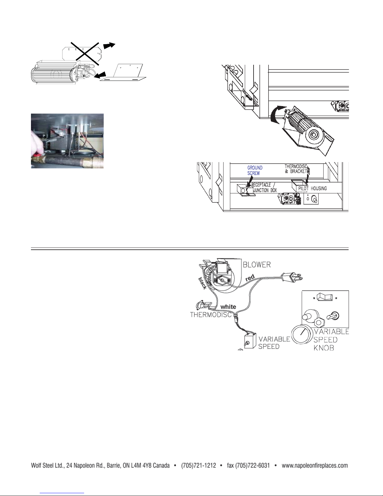
Tilt the blower assembly onto its side. Slide it past the controls and into the clip (C). Secure to the threaded stud using
the lock washer and wing nut provided. Ensure that the blower does not touch the fi replace base or the fi rebox.
Attach the connectors from the black and white wires to the thermodisc and secure the thermodisc bracket to the
securing stud at the bottom left of the unit using a lock washer and wing nut. Ensure that the thermodisc touches the
fi rebox wall.
B
A
Continue with ALL MODELS
C
W415-0135 / B / 01.11.07
MODEL SERIES 40 :
Remove the blower from its mounting bracket and attach to the bracket
supplied with the fi replace. This bracket is found secured on the mount-
ing studs located at the
bottom of the vent side
wall .
Position the vibration reducing pad, centered, onto the 2 threaded studs,
piercing 2 holes into the pad. The blower must be able to be positioned
entirely onto the pad.
Tilt the blower onto its side and slide it past the controls. Position the blower onto the studs.
The blower bracket contains slots that allow the blower to
be positioned away from the intended gas supply hole.
Secure the blower using the lock washers and wing nuts provided.
Remove the "Z" shaped mounting bracket secured to
the burner, by the pilot. Remove the thermodisc from
the bracket supplied in the blower kit and attach to the
mounting bracket.
Do not overtighten thermodisc or distort housing.
Attach the connectors from the black and white wires to the thermodisc.
Continue with ALL MODELS.
ALL MODELS:
Attach the connectors from the black and red wires to the
blower.
Attach and secure the variable speed switch using the nut
provided. Plug the harness cord into the receptacle.
The wire harness provided in this kit is a universal harness. When installed, ensure that any excess wire is contained,
preventing it from making contact with moving or hot objects.
Because the blower is thermally activated, when turned on, it will automatically start approximately 15-30 minutes
after lighting the fi replace and will run for approximately 30-45 minutes after the fi replace has been turned off. Use
of the fan increases the output of heat.
 Loading...