

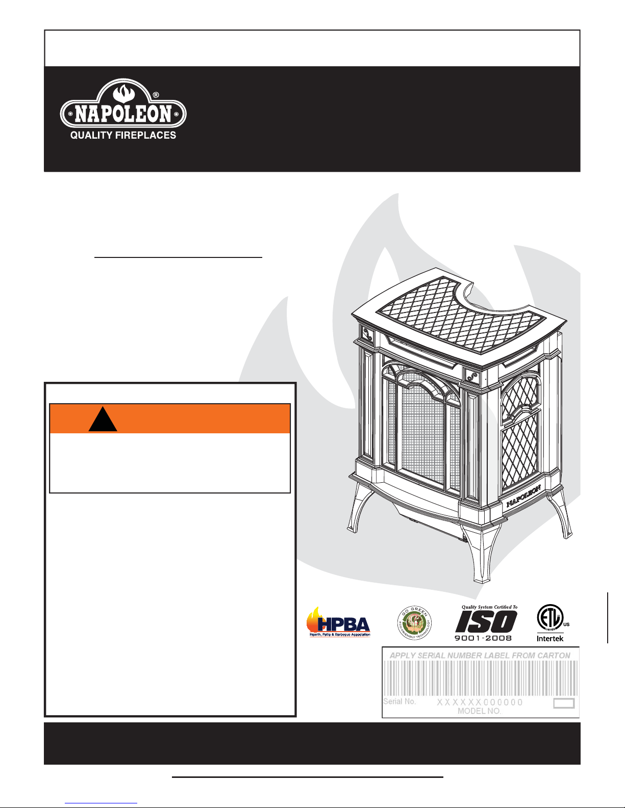
Napoleon GVFS20P, GVFS20N Installation And Operating Instructions Manual
INSTALLER: LEAVE THIS MANUAL WITH THE APPLIANCE.
CONSUMER: RETAIN THIS MANUAL FOR FUTURE REFERENCE.
INSTALLATION AND
OPERATING INSTRUCTIONS
CERTIFIED UNDER CANADIAN AND AMERICAN NATIONAL STANDARDS: ANSI Z21.11.2B, VOLUME II FOR UNVENTED ROOM HEATERS.
GVFS20P
PROPANE
GVFS20N
NATURAL GAS
UNVENTED MILLIVOLT
1
SYSTEM
CERTIFIED FOR THE UNITED STATES USING ANSI METHODS.
SAFETY INFORMATION
!
WARNING
If the information in these instructions are
not followed exactly, a fi re or explosion
may result causing property damage,
personal injury or loss of life.
- Do not store or use gasoline or other fl ammable
vapors and liquids in the vicinity of this or any
other appliance.
- WHAT TO DO IF YOU SMELL GAS:
• Do not try to light any appliance.
• Do not touch any electrical switch; do not use
any phone in your building.
• Immediately call your gas supplier from a
neighbour’s phone. Follow the gas supplier’s
instructions.
• If you cannot reach your gas supplier, call the
fi re department.
- Installation and service must be performed by a
qualifi ed installer, service agency or the supplier.
- This is an unvented gas-fi red heater that
uses air (oxygen) from the room in which it is
installed. Provisions for adequate combustion and
ventilation air must be provided.
Wolf Steel Ltd., 24 Napoleon Rd., Barrie, ON, L4M 4Y8 Canada /
103 Miller Drive, Crittenden, Kentucky, USA, 41030
Phone (705)721-1212 • Fax (705)722-6031 • www.napoleonfi replaces.com • ask@napoleonproducts.com
10.00$
1.23
W415-0559 / C / 10.04.10

2
TABLE OF CONTENTS
1.0 INSTALLATION OVERVIEW 3
2.0 INTRODUCTION 4
3.0 INSTALLATION 8
4.0 FINISHING 12
5.0 OPTIONAL BLOWER INSTALLATION 14
6.0 OPERATION 15
7.0 ADJUSTMENT 16
8.0 MAINTENANCE 17
9.0 REPLACEMENTS 19
10.0 TROUBLE SHOOTING 21
11.0 WARRANTY 24
12.0 SERVICE HISTORY 25
2.1 DIMENSIONS 5
2.2 GENERAL INSTRUCTIONS 5
2.3 GENERAL INFORMATION 6
2.4 RATING PLATE INFORMATION 7
3.1 COMBUSTION AND VENTILATION AIR PROVISIONS 8
3.2 DETERMINING CONFINED OR UNCONFINED SPACE 9
3.3 GAS INSTALLATION 10
3.4 OPTIONAL WALL SWITCH / THERMOSTAT 11
3.5 MOBILE HOME INSTALLATION 11
4.1 CAST FRONT INSTALLATION AND REMOVAL 12
4.2 SCREEN INSTALLATION AND REMOVAL 12
4.3 LOGO PLACEMENT 12
4.4 LOG PLACEMENT 13
5.1 BLOWER INSTALLATION AND CONNECTION 14
5.2 SWITCH CONNECTIONS 14
7.1 VENTURI ADJUSTMENT 16
7.2 FLAME CHARACTERISTICS 16
8.1 OXYGEN DEPLETION SENSOR PILOT CLEANING 17
8.3 PILOT INDICATOR LIGHT BATTERY REPLACEMENT 18
8.2 ORIFICE REPLACEMENT 18
NOTE: Changes, other than editorial, are denoted by a vertical line in the margin.
W415-0559 / C / 10.04.10
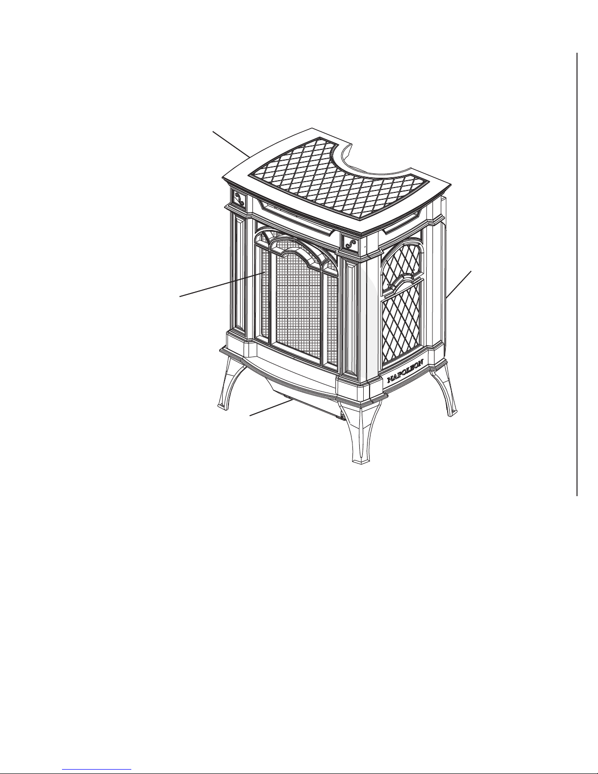
1.0 INSTALLATION OVERVIEW
Cast top, see “FINISHING - CAST
FRONT INSTALLATION AND
REMOVAL” section.
Door, see “FINISHING
- SCREEN
INST ALLA TION AND
REMOVAL” section.
3
Blower, see “OPTIONAL
BLOWER
INSTALLATION” section.
Rating Plate, see
“RATING PLATE
INFORMATION”
section.
W415-0559 / C / 10.04.10

4
2.0 INTRODUCTION
• THIS APPLIANCE IS HOT WHEN OPERATED AND CAN CAUSE SEVERE BURNS IF CONTACTED.
• ANY CHANGES TO THIS APPLIANCE OR ITS CONTROLS CAN BE DANGEROUS AND IS PROHIBITED.
• Under no circumstances should this appliance be modifi ed.
• Do not operate appliance before reading and understanding operating instructions. Failure to operate
appliance according to operating instructions could cause fi re or injury.
• Risk of burns. The appliance should be turned off and cooled before servicing.
• Do not install damaged, incomplete or substitute components.
• Risk of cuts and abrasions. Wear protective gloves and safety glasses during installation. Sheet metal edges
may be sharp.
• Provide adequate ventilation and combustion air. Provide adequate accessibility clearance for servicing and
operating the appliance. Never obstruct the front opening of the appliance.
• If the appliance shuts off, do not re-light until you provide fresh air. If appliance keeps shutting off, have it
serviced. Keep burner and control compartment clean.
• Do not burn wood or other materials in this appliance.
• Children and adults should be alerted to the hazards of high surface temperature and should stay away to
avoid burns or clothing ignition.
• Young children should be carefully supervised when they are in the same room as the appliance. Toddlers,
young children and others may be susceptible to accidental contact burns. A physical barrier is recommended
if there are at risk individuals in the house. To restrict access to an appliance, install an adjustable safety gate
to keep toddlers, young children and other at risk individuals out of the room and away from hot surfaces.
• Due to high temperatures, the appliance should be located out of traffi c and away from furniture and
draperies.
• Ensure you have incorporated adequate safety measures to protect infants/toddlers from touching hot
surfaces.
• Clothing or other fl ammable material should not be placed on or near the appliance.
• Check with your local hearth specialty dealer for safety screens and hearth guards to protect children from
hot surfaces. These screens and guards must be fastened to the fl oor.
• Any safety screen or guard removed for servicing must be replaced prior to operating the appliance.
• It is imperative that the control compartments, burners and circulating blower and its passageway in the
appliance are kept clean. The appliance should be inspected before use and at least annually by a qualifi ed
service person. More frequent cleaning may be required due to excessive lint from carpeting, bedding
material, etc. The appliance area must be kept clear and free from combustible materials, gasoline and other
fl ammable vapours and liquids.
• Furniture or other objects must be kept a minimum of 4 feet away from the front of the appliance.
• Do not use this appliance if any part has been under water. Immediately call a qualifi ed service technician
to inspect the appliance and to replace any part of the control system and any gas control which has been
under water.
• Do not allow fans to blow directly into the appliance. Avoid any drafts that alter burner fl ame patterns.
• Do not use a blower insert, heat exchanger insert or other accessory not approved for use with this appliance.
• Carbon or soot should not occur in a vent free appliance as it can distribute into the living area of your home.
If you notice any signs of carbon or soot, immediately turn off your appliance and arrange to have it serviced
by a qualifi ed technician before operating it again.
• Keep the packaging material out of reach of children and dispose of the material in a safe manner. As with all
plastic bags, these are not toys and should be kept away from children and infants.
• As with any combustion appliance, we recommend having your appliance regularly inspected and serviced as
well as having a Carbon Monoxide Detector installed in the same area to defend you and your family against
Carbon Monoxide.
• The appliance screen must be in place when the appliance is operating.
• Ensure clearances to combustibles are maintained when building a mantel or shelves above the appliance.
Elevated temperatures on the wall or in the air above the appliance can cause melting, discolouration or
damage to decorations, a T.V. or other electronic components.
!
WARNING
3.4B
W415-0559 / C / 10.04.10

2.1 DIMENSIONS
19 1/4"
9
5
/8"
25 3/8"
15 3/4"
2.2 GENERAL INSTRUCTIONS
* CARBON MONOXIDE POISONING MAY LEAD TO DEATH
EARLY SIGNS OF CARBON MONOXIDE POISONING RESEMBLE THE FLU, WITH HEADACHE,
DIZZINESS AND/OR NAUSEA. IF YOU HAVE THESE SIGNS, THE HEATER MAY NOT BE WORKING
PROPERLY. GET FRESH AIR AT ONCE! HAVE HEATER SERVICED.
SOME PEOPLE---PREGNANT WOMEN, PERSONS WITH HEART OR LUNG DISEASE, ANEMIA,
THOSE UNDER THE INFLUENCE OF ALCOHOL, THOSE AT HIGH ALTITUDES--- ARE MORE
AFFECTED BY CARBON MONOXIDE THAN OTHERS.
!
WARNING
5
THE APPLIANCE IS ONLY FOR USE WITH THE TYPE OF GAS INDICATED ON THE RATING PLATE.
THIS APPLIANCE IS NOT CONVERTIBLE FOR USE WITH OTHER GASES.
OBJECTS PLACED IN FRONT OF THE HEATER SHOULD BE KEPT A MINIMUM OF 48” AWAY FROM
THE FRONT FACE OF THE APPLIANCE.
USE ONLY WOLF STEEL APPROVED OPTIONAL ACCESSORIES AND REPLACEMENT PARTS WITH
THIS APPLIANCE. USING NON-LISTED ACCESSORIES AND REPLACEMENT PARTS (BLOWERS,
LOUVRES, TRIMS, GAS COMPONENTS, VENT COMPONENTS, ETC.) COULD RESULT IN A SAFETY
HAZARD AND WILL VOID THE LIMITED LIFETIME WARRANTY.
NOT DESIGNED FOR USE WITH A GLASS DOOR. SCREEN MUST BE CLOSED WHEN APPLIANCE IS
IN OPERATION.
THIS APPLIANCE MUST NOT BE INSTALLED IN A BEDROOM OR BATHROOM.
This gas appliance should be installed and serviced by a qualifi ed installer to conform with local codes.
Installation practices vary from region to region and it is important to know the specifi cs that apply to your
area, for example: in Massachusetts State:
• The appliance off valve must be a “T” handle gas cock.
• The fl exible connector must not be longer than 36“.
• The appliance is not approved for installation in a bedroom or bathroom unless the appliance is a direct
vent sealed combustion product.
• A carbon monoxide detector is required in all rooms containing gas fi red appliances.
• WARNING: This product must be installed by a licensed plumber or gas fi tter when installed within the
commonwealth of Massachusetts.
• Un-vented room appliance shall be installed in accordance with 527 CMR 30.00 and 248 CMR 3.00
through 7.00.
• Sellers of un-vented propane or natural gas-fi red space / room appliances shall provide to each purchaser
a copy of 527 CMR 30.00 upon the sale of the appliance from http://www.napoleonfi replaces.com/
Webshare/installation_manuals/mass_requirements.pdf
W415-0559 / C / 10.04.10

6
In absence of local codes, install the appliance to the current National Fuel Gas Code, ANSI Z223.1
Installation Code which can be obtained from:
American National Standards Institute Inc. or National Fire Protection Association Inc.
1430 Broadway Batterymarch Park
New York, NY 10018 Quincy, MA 02269
The appliance and its individual shutoff valve must be disconnected from the gas supply piping system during
any pressure testing of that system at test pressures in excess of 1/2 psig (3.5 kPa). The appliance must be
isolated from the gas supply piping system by closing its individual manual shutoff valve during any pressure
testing of the gas supply piping system at test pressures equal to or less than 1/2 psig (3.5 kPa). When
installed with a blower the junction box must be electrically connected and grounded in accordance with local
codes. In the absence of local codes, use the current ANSI / NFPA 70 National Electric Code. In the case
where the blower is equipped with a power cord it must be connected into a properly grounded receptacle.
The grounding prong must not be removed from the cord plug.
We suggest that our gas
As long as the required clearance to combustibles is maintained,
the most desirable and benefi cial location for the appliance is in the
center of a building, thereby allowing the most effi cient use of the
heat created. The location of windows, doors and the traffi c fl ow in
the room where the appliance is to be located should be considered.
www.ncertied.org
hearth products be installed
and serviced by professionals
who are certied in the U.S.
by the National Fireplace
®
Institute
Specialists
(NFI) as NFI Gas
If the appliance is installed directly on carpeting, vinyl tile or other
combustible material other than wood fl ooring, the appliance shall be installed on a metal or wood panel
extending the full width and depth. NOTE: This does not apply to stoves.
* Air shortage caused by an inadequate air supply, improper log positions, the addition of foreign or
unapproved materials or the failure to properly maintain the appliance, may result in incomplete combustion of
the fuel. Incomplete combustion results in soot being deposited inside the fi rebox as well as surfaces outside
the appliance. If any soot deposits are observed, shut off the appliance immediately and arrange for it to be
serviced by a qualifi ed technician.
2.3 GENERAL INFORMATION
FOR YOUR SA TISFACTION, THIS APPLIANCE HAS BEEN TEST-FIRED TO ASSURE ITS OPERATION AND
QUALITY!
Altitude (FT) 0-2,000 0-2,000
Max. Input (BTU/HR) 23,000 23,000
Min. Inlet Gas Supply Pressure 4.5" Water Column 11" Water Column
Max. Inlet Gas Supply Pressure 7" Water Column 13" Water Column
Manifold Pressure (Under Flow Conditions) 3.5" Water Column 10" Water Column
When the appliance is installed at elevations above 2,000ft, and in the absence of specifi c recommendations from
the local authority having jurisdiction, the certifi ed high altitude input rating shall be reduced at the rate of 4% for each
additional 1,000ft. Expansion / contraction noises during heating up and cooling down cycles are normal and to be
expected.
4.2C
GVFS20
NG LP
No external electricity (1 10 volts or 24volts) is required for the gas system operation.
This appliance is equipped with a pilot light safety system referred to as an oxygen depletion sensor and is designed to
turn off the appliance if not enough fresh air is available.
W415-0559 / C / 10.04.10

2.4 RATING PLATE INFORMATION
OF THIS OF THIS
RNING:RNIN
DO NOT ADD ANY MATERIAADD ANY MATERIA
WILL COME IN CONTACT WILL COME IN CONTAC
THAT SUPPLIED BY THE MANTHAT SUPPLIED BY THE MA
SCREEN MUST BE IN PLACEEEN MUST BE IN PLAC
00
mm
))
BTUBTU
//hh0000
TBT
UU
//
hh
WWATERER
COLUMCOLUM
NN111WWAATETE
RR
CCOOLUM
N
RESSUREESSURE
::
3"13"
WATT
ERER
CCOOLUMLUM
820.63366ILOT ILOT
O
COXYPROTEC
TT
OROR::# 8#
4366
YYHHAAVVII
NN
GGJJURURISIS
D
I
CC
TIOTIO
FUEL
..
PP
TARIO L4M 4Y8 CANADA
RIO L4M 4Y8 CANAD
CONFORMS TO: ANSI Z21.11.2a-2008, UNVENTED GAS FIRED ROOM HEATER
THIS IS A GAS-FIRED UNVENTED
ROO M HEATER THAT REQUIRES
ADEQUATE COMBUSTION
AND VENTILATION AIR.
THIS APPLIANCE IS NOT FIELD
CONVERTIBLE FOR USE WITH
MODEL GVFS20-N
**0-2000FT (0-610m)
23,000 BTU/h
18,000BTU/h
MANIFOLD PRESSURE: 3.5" WATER COLUMN
MINIMUM SUPPLY PRESSURE: 4.5" WATER COLUMN
MAXIMUM SUPPLY PRESSURE: 7.0" WATER COLUMN
OPERATING PILOT OXYPROTECTOR: # 8214
**ABOVE 2,000FT, CONSULT LOCAL AUTHORITY HAVING JURISDICTION
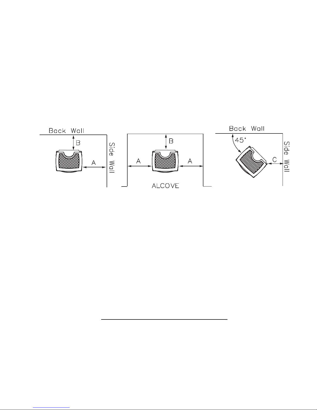
MINIMUM CLEARANCE TO COMBUSTIBLE MA TERIALS
A 4”
B 2"
C 2"
48” MIN I M U M TO CEILING FROM STOVE TOP
WOLF STEEL LTD.
24 NAPOLEON ROAD. BARRIE, ONTARIO L4M 4Y8 CANADA
OTHER FUELS.
ALTITUDE
INPUT
REDUCED INPUT
MANIFOLD PRESSURE: 10" WATER COLUMN
MINIMUM SUPPLY PRESSURE: 11" WATER COLUMN
SIT CONTROL: # 820.638
MAXIMUM SUPPLY PRESSURE: 13" WATER COLUMN
SIT CONTROL: # 820.636
OPERATING PILOT OXYPROTECTOR: # 8436
NOT FOR USE WITH SOLID FUEL.
WARNING: DO NOT ADD ANY MATERIAL TO THE APPLIANCE, WHICH
o
B
45
A
C
THAT SUPPLIED BY THE MANUFACTURER WITH THE APPLIANCE.
SCREEN MUST BE IN PLACE WHILE THE APPLIANCE IS IN OPERATION.
WILL COME IN CONTACT WITH THE FLAMES, OTHER THAN
THIS UNIT IS NOT APPROVED FOR
BEDROOM, BATHROOM AND
BED-SITTING ROOM
INSTALLATION.
MODEL GVFS20-P
**0-2000FT (0-610m)
23,000 BTU/h
B
18,000BTU/h
1
XYPROTE
D
FUEL
ELECTRICAL RATING: 115V 0.82AMP, 60HZ
SERIAL NUMBER
OPTIONAL FAN KIT: GS-64KT
GVFS20
DIAGRAM TO AID THE OPERATION
OF THIS FIREPLACE
FLAME
ADJUSTMENT
ON / OFF
CONTROL
IGNITOR
W385-0337 / J
7
INSTALLER: It is your responsibility to check off the appropriate box on the rating plate according to
the model, venting and gas type of the appliance.
For rating plate location, see “INSTALLATION OVERVIEW” section.
This illustration is for reference only. Refer to the rating plate on the appliance for accurate information.
W415-0559 / C / 10.04.10
8
3.0 INSTALLATION
THIS GAS HEATER SHOULD BE INSTALLED AND SERVICED BY A QUALIFIED INSTALLER to conform
with local codes. Installation practices vary from region to region and it is important to know the specifi cs that
apply to your area.
Provide adequate ventilation and combustion air. Provide adequate accessibility clearance for servicing
and operating the heater. Never obstruct the front opening of the heater.
As long as clearances to combustibles is kept within the required distances, the most desirable and benefi cial
location for a heater is in the centre of a building, thereby allowing the most effi cient use of the heat created.
The location of windows, doors and the traffi c fl ow in the room where the heater is to be located should be
considered.
MAINTAIN THESE MINIMUM CLEARANCES TO COMBUSTIBLES:
A. 4" B. 2"* C. 2"
Heater should not be installed directly on carpeting.
Minimum 48" from top to ceiling.
* If less than 5" clearance is maintained between the back of the heater and the back wall, it will be necessary
to disconnect the gas pipe to move the heater out for installation or service of the blower.
3.1 COMBUSTION AND VENTILATION AIR PROVISIONS
This appliance shall not be installed in a confi ned space or unusually tight construction unless provisions are
provided for adequate combustion and ventilation air.
The National Fuel Gas Code, ANSI Z223.1 / NFPA 54 defi nes a confi ned space as a space whose volume is
less than 50 cubic feet per 1,000 Btu per hour (4.8 m3 per kw) of the aggregate input rating of all appliances
installed in that space and an unconfi ned space as a space whose volume is not less than 50 cubic feet per
1,000 Btu per hour (4.8 m3 per kw) of the aggregate input rating of all appliances installed in that space.
Rooms communicating directly with the space in which the appliances are installed, through openings not
furnished with doors are considered a part of the unconfi ned space.
The GVFS20 is rated at 23,000 BTU's per hour for natural gas and propane gas and therefore requires a
minimum unconfined space of 1,150 cubic feet.
17.1A
W415-0559 / C / 10.04.10

9
A
A
LENGTH
HEIGHT
ROOM 2
ROOM 1
WIDTH
3.2 DETERMINING CONFINED OR UNCONFINED SPACE
To determine the volume of the room where the appliance is to be installed, multiply the width x the length x
the ceiling height of that room measured in feet. If any adjoining rooms are connected by grilles or openings
such as kitchen pass-throughs, etc., the volume of those rooms may be added to the total.
Multiply the room volume by 1000 and divide this amount by 50 to determine the maximum BTU/hr that the
space can support with adequate combustion and ventilation air.
dd the Btu/hr of all fuel burning appliances located within the space such as gas furnace, gas water
appliance, etc. Do not include direct vent gas appliances which draw their input and output air from and to the
outdoors.
Unusually tight construction is defi ned as construction where:
A) Walls and ceilings exposed to the outside atmosphere have a continuous water vapour retarder with a
rating of 1 perm (6 x 10-11 kg per pa-sec-m2) or less with openings gasketed or sealed, and
!
WARNING
IF THE AREA IN WHICH THE APPLIANCE MAY BE OPERATED IS SMALLER THAN THAT DEFINED AS
AN UNCONFINED SP ACE OR IF THE BUILDING IS OF UNUSUALLY TIGHT CONSTRUCTION, PROVIDE
ADEQUA TE COMBUSTION AND VENTILATION AIR BY ONE OF THE METHODS DESCRIBED IN THE
NA TIONAL FUEL GAS CODE ANSI Z223.1/ NFPA 54 , AIR FOR COMBUSTION AND VENTILATION, OR THE
APPLICABLE LOCAL CODE.
IF THE AREA IN WHICH THE APPLIANCE MAY BE OPERATED DOES NOT MEET THE REQUIRED VOLUME
FOR INDOOR COMBUSTION AIR, COMBUSTION AND VENTILATION AIR SHALL BE PROVIDED BY ONE
OF THE METHODS DESCRIBED IN THE ANSI Z223.1 / NFPA 54, THE INTERNATIONAL FUEL GAS CODE,
OR APPLICABLE LOCAL CODES.
B) Weather stripping has been added on openable windows and doors, and
C) Caulking or sealants are applied to areas such as joints around window and door frames, between sole
plates and fl oors, between wall-ceiling joints, between wall panels, at penetrations for plumbing, electrical,
and gas lines, and at other openings.
n unvented room appliance is recommended for use as a secondary heat source rather than as a primary
source. Gas combustion produces water vapour which could occur at the rate of approximately one ounce of
water for every 1,000 BTU/hr of gas input. During the cold weather season, indoor humidity levels tend to be
low. Consequently, this water vapour can enhance the living space. However if a problem should occur:
A) Ensure suffi cient combustion and circulation air
B) Use a dehumidifi er
C) Do not use the unvented room appliance as a primary heat source
Without suffi cient fresh air for proper operation, poor fuel combustion can result. Carbon Monoxide is a result
of poor combustion.
If additional fresh air is required, use one of the methods described in the National Fuel
Gas Code, ANSI Z223.1 / NFPA54 or the applicable local code.
Room Volume = Length x Width x Height
Max BTU/hr = Room Volume x 1000 / 50
If for example:
The length of the rooms is 10 feet,
The width of Room 1 is 10 feet,
The width of Room 2 is 15 feet,
The height of the rooms is 8 feet.
The volume of Room 1: 10x10x8 = 800 cubic feet
The volume of Room 2: 10x15x8 = 1200 cubic feet
19.1B
W415-0559 / C / 10.04.10
 Loading...