

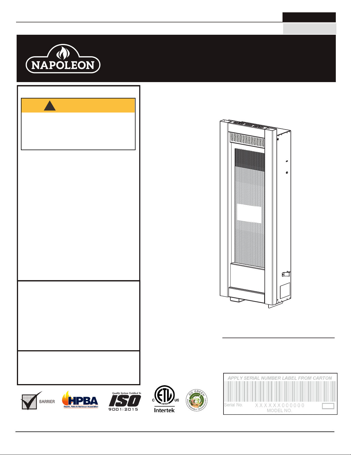
Napoleon GT8P Installation And Operation Manual
NATURAL GAS MODELS:
GT8N
ADD PRODUCT CODE HERE (TRADE GOTHIC LT STD FONT)
ENGLISH
PROPANE GAS MODELS:
SAFETY INFORMATION
!
WARNING
FIRE OR EXPLOSION HAZARD
Failure to follow safety warnings exactly
could result in serious injury, death, or
property damage.
- Do not store or use gasoline or other
fl ammable vapors and liquids in the vicinity of
this or any other appliance.
- WHAT TO DO IF YOU SMELL GAS:
• Do not try to light any appliance.
• Do not touch any electrical switch; do not
use any phone in your building.
• Immediately call your gas supplier from a
neighbour’s phone. Follow the gas
supplier’s instructions.
• If you cannot reach your gas supplier, call
the fi re department.
GT8P
FRENCH
PG. 43
INSTALLATION AND
ADD MANUAL TITLE
OPERATION MANUAL
Product Name / Code
Torch
(MUST use title from Price Book)
ADD ____ ILLUSTRATED
SAFETY
ADD PRODUCT IMAGE
BARRIER
(GT8 illustrated)
®
- Installation and service must be
performed by a qualifi ed installer, service
agency, or the supplier.
This appliance may be installed in an aftermarket,
permanently located, manufactured home (USA
only) or mobile home, where not prohibited by
local codes.
This appliance is only for use with the type of gas
indicated on the rating plate. This appliance is
not convertible for use with other gases, unless
a certifi ed kit is used.
INSTALLER:
Leave this manual with the appliance
CONSUMER:
Retain this manual for future reference
Wolf Steel Ltd., 24 Napoleon Rd., Barrie, ON, L4M 0G8 Canada / 103 Miller Drive, Crittenden, Kentucky, USA, 41030
Phone 1 (866) 820-8686 • www.napoleon.com • hearth@napoleon.com
CSA 2.22 AND ANSI Z21.50 FOR VENTED DECORATIVE GAS APPLIANCES
CSA /
INTERTEK
LOGO
FOR INDOOR USE ONLY
CERTIFIED TO THE CANADIAN AND AMERICAN NATIONAL STANDARDS:
IF INSTALLATION + OPERATION, ADD SERIAL
NUMBER LABEL HERE
IF SEPARATE MANUALS, ADD “PLACE
BARCODE LABEL ON THE OWNER’S MANUAL”
$10.00
W415-1367 / B / 01.09.19

EN
HOT GLASS WILL CAUSE
BURNS.
DO NOT TOUCH GLASS UNTIL
COOLED.
NEVER ALLOW CHILDREN TO
TOUCH GLASS.
!
DANGER
A barrier designed to reduce the risk of burns from the
hot viewing glass is provided with this appliance and
shall be installed for the protection of children and other
at-risk individuals.
!
WARNING
safety information
• This appliance is hot when operated and
can cause severe burns if contacted.
• Any changes or alterations to this
appliance or its controls can be
dangerous and is prohibited.
• Do not operate appliance before reading and
understanding operating instructions. Failure
to operate appliance according to operating
instructions could cause fi re or injury.
• Ensure the glass door is opened or removed
when lighting the pilot for the fi rst time and
when the gas supply has run out.
• Risk of fi re or asphyxiation, do not operate
appliance with fi xed glass removed and never
obstruct the front opening of the appliance.
• Do not connect 110 volts to the control valve,
with the exception of models; GSST8 and
GT8.
• Risk of burns. The appliance should be turned off and cooled before servicing.
• Do not install damaged, incomplete or substitute components.
• Risk of cuts and abrasions. Wear protective gloves, protective footwear, and safety glasses during
installation. Sheet metal edges may be sharp.
• Do not burn wood or other materials in this appliance.
• Provide adequate ventilation and combustion air. Provide adequate accessibility clearance for servicing
and operating the appliance.
• High pressure will damage valve. Disconnect gas supply piping before pressure testing gas line at
test pressures above 1/2 psig. Close the manual shut-off valve before pressure testing gas line at test
pressures equal to or less than 1/2 psig (35mb).
• The appliance must not be operated at temperatures below freezing (32°F / 0°C). Allow the appliance
to warm to above freezing prior to operation, with the exception of models; GSS36, GSS42; these
appliances are suitable for 0°F / -18°C.
• Children and adults should be alerted to hazards of high surface temperature and should stay
away to avoid burns or clothing ignition.
• Young children should be carefully supervised when they are in the same room as the
appliance. Toddlers, young children and others may be susceptible to accidental contact
burns. A physical barrier is recommended if there are at risk individuals in the house. To
restrict access to an appliance or stove, install an adjustable safety gate to keep toddlers,
young children and other at risk individuals out of the room and away from hot surfaces.
• Clothing or other fl ammable material should not be placed on or near the appliance.
• Due to high temperatures, the appliance should be located out of traffi c and away from
furniture and draperies.
• Furniture or other objects must be kept a minimum of 4 feet (1.22m) away from the front of the appliance.
• Ensure you have incorporated adequate safety measure to protect infants/toddlers from touching hot
surfaces.
• Even after the appliance is off, it will remain hot for an extended period of time.
• Check with your local hearth specialty dealer for safety screens and hearth guards to protect children
from hot surfaces. These screens and guards must be fastened to the fl oor.
• Any safety screen, guard or barrier removed for servicing the appliance, must be replaced prior
to operating the appliance.
• It is imperative that the control compartments, burners and circulating blower and its passageway in the
appliance and venting system are kept clean. The appliance and its venting system should be inspected
before use and at least annually by a qualifi ed service person. More frequent cleaning may be required
due to excessive lint from carpeting, bedding material, etc. The appliance area must be kept clear and
free from combustible materials, gasoline and other fl ammable vapors and liquids.
• If the appliance shuts off, do not re-light until you provide fresh air. If appliance keeps shutting off, have it
serviced. Keep burner and control compartment clean.
• Under no circumstances should this appliance be modifi ed.
• Do not allow wind or fans to blow directly into the appliance. Avoid any drafts that alter burner fl ame
patterns.
2
W415-1367 / B / 01.09.19
due to excessive lint from carpeting, bedding material, etc. The appliance area must be kept clear and
free from combustible materials, gasoline and other fl ammable vapors and liquids.
• If the appliance shuts off, do not re-light until you provide fresh air. If appliance keeps shutting off, have it
serviced. Keep burner and control compartment clean.
• Under no circumstances should this appliance be modifi ed.
• Do not allow wind or fans to blow directly into the appliance. Avoid any drafts that alter burner fl ame
patterns.
HOT GLASS WILL CAUSE
BURNS.
DO NOT TOUCH GLASS UNTIL
COOLED.
NEVER ALLOW CHILDREN TO
TOUCH GLASS.
!
DANGER
A barrier designed to reduce the risk of burns from the
hot viewing glass is provided with this appliance and
shall be installed for the protection of children and other
at-risk individuals.
!
WARNING
!
WARNING
WARNING
!
WARNING:
Electric
This product can expose you to chemicals including lead and lead compounds,
Gas, Wood
which are known to the State of California to cause cancer, and chemicals including BBP and
DEHP, which are known to the State of California to cause birth defects or other reproductive
harm. For more information, go to www.P65Warnings.ca.gov.
!
AVERTISSEMENT:
Ce produit peut vous exposer à des substances chimiques incluant le
plomb et les composés de plomb qui, selon l’État de Californie, causeraient le cancer, et des
substances chimiques incluant le BBP et DEHP qui, selon d’État de Californie, causeraient des
malformations congénitales ou autres dangers pour la reproduction.
Pour de plus amples renseignements, visitez le www.P65Warnings.ca.gov.
!
ADVERTENCIA:
Este producto puede exponerlo a productos químicos, entre ellos, plomo
y compuestos con plomo, que el Estado de California reconoce como causantes de cáncer, y
productos químicos, entre ellos, bencilbutilftalato (BBP, por sus siglas en inglés) y di(2-etilhex-
il) ftalato (DEHP, por sus siglas en inglés), que el Estado de California reconoce como caus-
antes de malformaciones congénitas u otros daños para la reproducción. Para obtener más
información, visite www.P65Warnings.ca.gov.
• Do not use a blower insert, heat exchanger insert or other accessory not approved for use with this
appliance.
• This appliance must not be connected to a chimney fl ue pipe serving a separate solid fuel burning
appliance.
• Do not use this appliance if any part has been under water. Immediately call a qualifi ed service technician
to inspect the appliance and to replace any part of the control system and any gas control which has
been under water.
• Do not operate the appliance with the glass door removed, cracked or broken. Replacement of the glass
should be done by a licensed or qualifi ed service person, if equipped.
• Do not strike or slam shut the appliance glass door, if equipped.
• Only doors / optional fronts certifi ed with the appliance are to be installed on the appliance.
• Keep the packaging material out of reach of children and dispose of the material in a safe manner. As
with all plastic bags, these are not toys and should be kept away from children and infants.
• Carbon or soot should not occur in a vent free appliance as it can distribute into the living area of your
home. If you notice any signs of carbon or soot, immediately turn off your appliance and arrange to have
it serviced by a qualifi ed technician before operating it again.
• If equipped, the screen must be in place (closed) when the appliance is in operation.
• When equipped with pressure relief doors, they must be kept closed while the appliance is operating
to prevent exhaust fumes containing carbon monoxide, from entering into the home. Temperatures of
the exhaust escaping through these openings can also cause the surrounding combustible materials to
overheat and catch fi re.
• Carbon monoxide poisoning may lead to death; early signs of carbon monoxide poisoning resemble the
fl u, with headache, dizziness and/or nausea. If you have these signs, the appliance may not be working
properly. Get fresh air at once! Have appliance serviced. Some people; pregnant women, persons with
heart or lung disease, anemia, those under the infl uence of alcohol, those at high altitudes are more
affected by carbon monoxide than others. Failure to keep the primary air opening(s) of the burner(s) clean
may result in sooting and property damage.
• As with any combustion appliance, we recommend having your appliance regularly inspected and
serviced as well as having a Carbon Monoxide Detector installed in the same area to defend you and
your family against Carbon Monoxide (not applicable for outdoor appliances).
• Ensure clearances to combustibles are maintained when building a mantel or shelves above the
appliance. Elevated temperatures on the wall or in the air above the appliance can cause melting,
discolouration or damage to decorations, a TV or other electronic components.
• For appliances equipped with a safety barrier; if the barrier becomes damaged, the barrier
shall be replaced with the manufacturer’s barrier for this appliance.
• Installation and repair should be done by a qualifi ed service person. It is imperative that control
• For outdoor products only: this appliance must not be installed indoors or within any structure that
• If applicable, the millivolt version of this appliance uses and requires a fast acting thermocouple. Replace
compartments, burners and circulating air passageways of the appliance be kept clean.
prevents or inhibits the exhaust gases from dissipating in the outside atmosphere.
only with a fast acting thermocouple supplied by Wolf Steel Ltd.
safety information
EN
!
WARNING:
which are known to the State of California to cause cancer, and chemicals including carbon
monoxide, which are known to the State of California to cause birth defects or other reproductive harm. For more information, go to www.P65Warnings.ca.gov.
This product can expose you to chemicals including lead and lead compounds,
Add California Prop 65 warning
!
FIRE RISK HAZARD / DELAYED IGNITION
High supply pressure will damage the valve / controls.
Disconnect the appliance main gas valve/control
from the supply piping when pressure testing that
system at pressures in excess of 1/2 psi (3.5 kPa).
Isolate the appliance with it’s shut off valve during
any pressure testing of the supply piping at
pressures equal to or less than 1/2 psi (3.5 kPa).
!
W415-1367 / B / 01.09.19
3

EN
table of contents
1.0 general information 5
1.1 dimensions 7
1.2 rating plate information 7
2.0 venting 8
2.1 cold climate 8
2.2 venting lengths and components 8
2.3 vent terminal clearances 9
2.4 horizontal termination 10
2.5 vertical termination 11
3.0 installation 12
3.1 horizontal installation 12
3.2 vertical installation 13
3.3 using flexible vent components 13
3.3.1 horizontal air terminal installation 14
3.3.2 vertical air terminal installation 15
3.3.3 appliance vent connection 15
3.4 gas installation 16
3.5 mobile home 16
4.0 framing 17
4.1 minimum clearance to combustibles 18
4.2 minimum enclosure clearances 19
4.3 nailing tab installation 20
4.4 stand-off assembly 20
5.0 finishing 21
5.1 mounting cabinet installation 21
5.2 safety barrier installation and removal 23
5.3 door removal 24
5.4 frame/front installation 25
5.5 glass media installation 26
5.6 LK8 light installation (optional) 27
6.0 electrical information 28
6.1 hard wiring connection 28
7.0 operation 29
8.0 adjustments 30
8.1 gas pressure adjustment 30
8.2 venturi adjustment 30
8.3 flame characteristics 30
9.0 maintenance 31
9.2 annual maintenance 32
9.1 care of glass 32
9.3 door glass replacement 33
10.0 replacement parts 34
10.1 overview 35
11.0 accessories 37
12.0 troubleshooting 38
13.0 warranty 40
14.0 service history 41
NOTE: Changes, other than editorial, are denoted by a line in the margin.
4
W415-1367 / B / 01.09.19

standard checklist
Installer, please fill out the following information:
Customer:
Address:
Date of Installation:
Location of appliance:
Installer:
Dealer/Distributor contact number:
Serial #:
Model:
Natural Gas: GT8N Propane: GT8P
1.0 general information
RATES AND EFFICIENCIES
NATURAL GAS PROPANE GAS
Maximum Input 6,000 6,000
Maximum Output 4,680 4,680
Efficiency 78% 78%
Minimum Inlet Gas Supply Pressure 4.5” (11mb) Water Column 11” (27mb) Water Column
Maximum Inlet Gas Supply Pressure 7” (17mb) Water Column 13” (32mb) Water Column
Manifold Pressure Under Flow Conditions 3.5” (9mb) Water Column 10” (25mb) Water Column
EN
This appliance is approved for bathroom, bedroom and bed-sitting room installations and is suitable for mobile
home installation. The natural gas model can only be installed in a mobile home that is permanently positioned
on its site and fueled with natural gas. This appliance may be installed in an aftermarket permanently located,
manufactured (mobile) home, where not prohibited by local codes.
This appliance is only for use with the type of gas indicated on the rating plate. This appliance is not convertible for
use with other gases, unless a certified kit is used.
Expansion / contraction noises during heating up and cooling down cycles are normal and are to be expected.
A barrier designed to reduce the risk of burns from the hot viewing glass is provided with the appliance
and must be installed.
Batteries must be disposed of according to the local laws and regulations. Some batteries may be
recycled, and may be accepted for disposal at your local recycling center. Check with your
municipality for recycling instructions.
W415-1367 / B / 01.09.19
5

EN
roof joist. If the appliance is installed directly on carpeting, vinyl tile or other combustible material other than wood fl ooring, the
appliance shall be installed on a metal or wood panel extending the full width and depth, unless otherwise tested.
general information
WARNING
!
• Always light the pilot whether for the first time or if the gas supply has run out, with the glass door opened
or removed.
• Provide adequate clearance for servicing and operating the appliance.
• Provide adequate ventilation.
• Never obstruct the front opening of the appliance.
• Objects placed in front of the appliance must be kept a minimum of 48” (121.9cm) from the front face of
the appliance.
• Surfaces around and especially above the appliance can become hot. Avoid contact when appliance is
operating.
• Fire risk. Explosion hazard.
• High pressure will damage valve. Disconnect gas supply piping before pressure testing gas line at test
pressures above 1/2 PSIG. Close the manual shut-off valve before pressure testing gas line at test
pressures equal to or less than 1/2 PSIG (35mb).
• Use only Wolf Steel approved optional accessories and replacement parts with this appliance using nonlisted accessories (blowers, doors, louvres, trims, gas components, venting components, etc.) could result
in a safety hazard and will void the warranty and certification.
• The appliance must not be operated at temperatures below freezing (32ºF / 0ºC). Allow the appliance to
warm, to above freezing prior to operation.
THIS GAS APPLIANCE MUST BE INSTALLED AND SERVICED BY A QUALIFIED INSTALLER to conform with local
codes. Installation practices vary from region to region and it is important to know the specifi cs that apply to your area, for
example in the state of Massachusetts:
• This product must be installed by a licensed plumber or gas fi tter when installed within the commonwealth of
Massachusetts.
• The appliance damper must be removed or welded in the open position prior to installation of an appliance insert or gas
log.
• The appliance off valve must be a “T” handle gas cock.
• The fl exible connector must not be longer than 36 inches (0.9m).
• A carbon monoxide detector is required in all rooms containing gas fi red appliances.
• The appliance is not approved for installation in a bedroom or bathroom unless the unit is a direct vent sealed
combustion product.
The installation must conform with local codes or, in absence of local
codes, the National Gas and Propane Installation Code CSA B149.1
in Canada, or the National Fuel Gas Code, ANSI Z223.1 / NFPA 54
in the United States. Suitable for mobile home installation if installed
in accordance with the current standard CAN/CSA Z240MH Series,
for gas equipped mobile homes, in Canada or ANSI Z223.1 and
NFPA 54 in the United States.
The appliance and its individual shutoff valve must be disconnected
from the gas supply piping system during any pressure testing
of that system at test pressures in excess of 1/2 psig (35 mb).
The appliance must be isolated from the gas supply piping system by closing its individual manual shutoff valve during any
pressure testing of the gas supply piping system at test pressures equal to or less than 1/2 psig (35 mb). When installed
with a blower or fan, the junction box must be electrically connected and grounded in accordance with local codes. In the
absence of local codes, use the current CSA C22.1 Canadian Electrical Code in Canada or the ANSI / NFPA 70 National
Electric Code in the United States. In the case where the blower is equipped with a power cord, it must be connected into a
properly grounded receptacle. The grounding prong must not be removed from the cord plug.
The following does not apply to inserts; as long as the required clearance to combustibles is maintained, the most desirable
and benefi cial location for an appliance is in the center of a building, thereby allowing the most effi cient use of the heat
created. The location of windows, doors and, the traffi c fl ow in the room where the appliance is to be located should be
considered. If possible, you should choose a location where the vent will pass through the house without cutting a fl oor or
www.ncertied.org
We suggest that our gas
hearth products be installed
and serviced by professionals
who are certied in the U.S.
by the National Fireplace
®
Institute
(NFI) as NFI Gas
Specialists
6
W415-1367 / B / 01.09.19
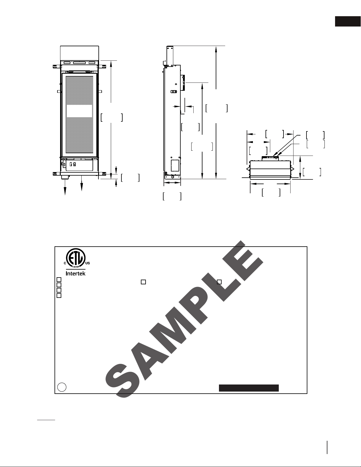
1.1 dimensions
SAMPLE
SAFETY
BARRIER
37 3/4"
959mm
1 1/4"
32mm
30 11/16"
779mm
43 3/4"
1111mm
general information
14"
356mm
7"
178mm
76mm
3"
127mm
5"
DIA.
DIA.
EN
1 1/4"
32mm
12"
305mm
ELECTRICAL
GAS
5 1/2"
140mm
INLET
INLET
1.2 rating plate information
RATING LABEL LOCATION: THE RATING LABEL IS LOCATED UNDER THE CONTROL PANEL AND IS
CHAINED TO THE APPLIANCE. DO NOT REMOVE.
CONFORMS TO ANSI Z21.50-2016, CERTIFIED TO CSA 2.22-2016 VENTED DECORATIVE GAS APPLIANCE
DIRECT VENT GAS APPLIANCE. APPROVED FOR BEDROOM, BATHROOM AND BED SITTING ROOM INSTALLATION. SUITABLE FOR MOBILE
HOME INSTALLATION IF INSTALLED IN ACCORDANCE WITH THE CURRENT STANDARD CAN/CSA Z240MH SERIES GAS EQUIPPED MOBILE
HOMES. IN CANADA OR IN THE UNITED STATES THE MANUFACTURED HOME CONSTRUCTION AND SAFETY STANDARD. TITLE 24 DFR,
PART 3280. WHEN THIS US STANDARD IS NOT APPLICABLE USE THE STANDARD FOR FIRE SAFETY CRITERIA FOR MANUFACTURED HOME
INSTALLATIONS, SITES AND COMMUNITIES, ANSI/NFPA 501A. FOR USE ONLY WITH BARRIER W565-0187. FOLLOW THE INSTALLATION
INSTRUCTIONS LOCATED IN THE INSTALLATION MANUAL.
9700539 (WSL)
GT8N MODEL GT8P
4001657 (NGZ)
(NATURAL GAS) (PROPANE)
4001658 (NAC)
0-4500FT (0-1370m) ALTITUDE 0-4500FT (0-1370m)
4001659 (WUSA)
6,000 BTU/h INPUT 6,000BTU/h
MANIFOLD PRESSURE: 3.5" WATER COLUMN MANIFOLD PRESSURE: 10" WATER COLUMN
MINIMUM SUPPLY PRESSURE: 4.5" WATER COLUMN MINIMUM SUPPLY PRESSURE: 11" WATER COLUMN
MAXIMUM SUPPLY PRESSURE: 7.0" WATER COLUMN MAXIMUM SUPPLY PRESSURE: 13" WATER COLUMN
WARNING: DO NOT ADD ANY MATERIAL TO THE
APPLIANCE, WHICH WILL COME IN CONTACT WITH
THE FLAMES, OTHER THAN THAT SUPPLIED BY THE
MANUFACTURER WITH THE APPLIANCE.
MINIMUM CLEARANCES TO COMBUSTIBLE MATERIALS
TOP 6" RECESSED DEPTH 7"
FLOOR 0" VENT TOP 2"
SIDES 0" VENT SIDES & BOTTOM 1"
BACK 1 1/2"
TOP, SIDES & BACK AS PER ABOVE. FOR FINISHING
MATERIAL, SEE OWNERS MANUAL.
ELECTRICAL RATING: 115v 0.82AMP, 60HZ
MINIMUM AND MAXIMUM HORIZONTAL VENT LENGTHS
ARE 4 INCHES AND 10 FEET RESPECTIVELY.
MINIMUM AND MAXIMUM VERTICAL VENT LENGTHS
ARE 36 INCHES AND 10 FEET RESPECTIVELY.
VENTED DECORATIVE GAS APPLIANCE NOT FOR USE WITH SOLID FUEL. FOR
USE WITH GLASS DOOR. CERTIFIED WITH THIS UNIT ONLY.
THE APPLIANCE MUST BE VENTED USING THE APPROPRIATE NAPOLEON VENT
KITS, SEE OWNERS INSTALLATION MANUAL FOR VENTING SPECIFICS. PROPER
REINSTALLATION AND RESEALING IS NECESSARY AFTER SERVICING THE
VENT-AIR INTAKE SYSTEM.
THIS APPLIANCE IS ONLY FOR USE WITH THE TYPE OF GAS INDICATED ON THE
RATING PLATE AND MY BE INSTALLED IN AN AFTERMARKET, PERMANENTLY
LOCATED, MANUFACTURED HOME (USA ONLY) OR MOBILE HOME WHERE NOT
PROHIBITED BY LOCAL CODES. SEE OWNER’S MANUAL FOR DETAILS. THIS
APPLIANCE IS NOT CONVERTIBLE FOR USE WITH OTHER GASES, UNLESS A
CERTIFIED KIT IS USED.SYSTEM.
WOLF STEEL LTD.
24 NAPOLEON ROAD. BARRIE, ONTARIO L4M 0G8 CANADA
SERIAL NUMBER:
GT8
W385-1981 / A
6 3/4"
171mm
This illustration is for reference only. Refer to the rating plate on the appliance for accurate information.
NOTE: The rating plate must remain with the appliance at all times. It must not be removed.
W415-1367 / B / 01.09.19
7

EN
venting
2.0 venting
WARNING
!
• Risk of fire. Maintain specified air space clearances to vent pipe and appliance.
• If venting is included with spacers, the vent system must be supported every 3 feet (0.9m) for both vertical
and horizontal runs. Use supports or equivalent combustibles. Use Wolf Steel Ltd. support ring assembly
W010-0370 or equivalent non-combustible strapping to maintain the minimum clearance to combustibles
for both vertical and horizontal runs. Spacers are attached to the inner pipe at predetermined intervals to
maintain an even air gap to the outer pipe. This gap is required for safe operation. A spacer is required at the
start, middle and end of each elbow to ensure this gap is maintained. These spacers must not be removed.
This appliane uses a 3” (76.2mm) exhaust / 5” (127mm) air intake vent pipe system. Refer to the section
applicable to your installation.
For safe and proper operation of the appliance follow the venting instruction exactly. Deviation from the minimum
vertical vent length can create difficulty in burner start-up and/or carboning. Under extreme vent configurations,
allow several minutes (5-15) for the flame to stabilize after ignition. Provide a means for visually checking the vent
connection to the appliance after the appliance is installed. Use a firestop, vent pipe shield or attic insulation shield
when penetrating interior walls, floor or ceiling.
NOTE: If for any reason the vent air intake system is disassembled; reinstall per the instructions
provided for the initial installation.
2.1 cold climate
For horizontal and vertical vent runs that pass through unheated spaces (attics, garages, crawl spaces) it is
recommended they be insulated with the insulation wrapped in a protective sleeve to minimize condensation.
Vent lengths terminating vertically should be kept to short lengths (maximum 5ft / 1.5m) in areas with colder
climates, especially in installations where the majority of the vent length is to be installed outside the building
envelope (such as in the attic).
2.2 venting lengths and components
The vent connection to the appliance can be viewed by removing the baffle from the top, inside of the firebox.
Use only Wolf Steel venting components. Minimum and maximum vent lengths, for both horizontal and vertical
installations, and air terminal locations for either system are set out in this manual and must be adhered to. Use
only Wolf Steel Ltd. flexible vent components with the Wolf Steel Ltd. GD179 termination kit. This
appliance uses a 3” (76.2mm) diameter exhaust and a 5” (127mm) diameter intake coaxial vent system.
All outer pipe joints of these venting systems must be sealed using Red RTV and/or Mill Pac high temperature
sealant (not supplied) hereafter referred to as high temperature sealant W573-0002 (Red RTV) and the high
temperature sealant W573-0007 (Mill Pac).
For vent systems that provide seals on the inner exhaust flue, only the outer air intake joints must be sealed using
a red high temperature silicone (RTV). This same sealant may be used on both the inner exhaust and outer intake
vent pipe joints of all other approved vent systems except for the exhaust vent pipe connection to the appliance
flue collar which must be sealed using the black high temperature sealant Mill Pac.
With flexible venting, in conjunction with the GD178 wall terminal kit, use either the 5 foot (1.5m) vent kit GDT5
or the 10 foot (3.1m) vent kit GDT10. These kits allow for extended horizontal venting of the appliance.
When using approved Wolf Steel venting components, use only the following termination kits: wall terminal kit
GD178, or 1/12 to 7/12 pitch roof terminal kit GDT110, 8/12 to 12/12 roof terminal kit GDT111, flat roof terminal
kit GDT112.
For optimum flame appearance and appliance performance, keep the vent length and number of
elbows to a minimum. The air terminal must remain unobstructed at all times. Examine the air terminal
at least once a year to verify that it is unobstructed and undamaged.Rigid and flexible venting systems
must not be combined. Different venting manufacturer components must not be combined. Vent
terminals shall not be recessed into a wall or siding.
These vent kits allow for either horizontal or vertical venting of the appliance. The maximum allowable horizontal
run is 7 feet (2.1m). The maximum allowable vertical vent length is 19 ½ feet (5.9m). The maximum number of vent
connections is two horizontally or three vertically (excluding the appliance and the air terminal connections) when
using flexible venting.
8
W415-1367 / B / 01.09.19
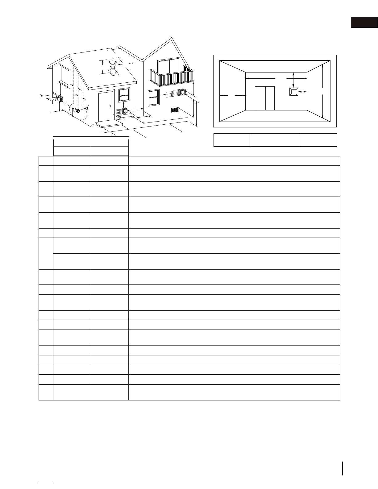
2.3 vent terminal clearances
D
E
N
H
C
F
H
A
O
B
O
B
venting
EN
COVERED BALCONY APPLICATIONS
Q
M
M
R
G
P
J
K
L
G
Q
= 3 feet
INSTALLATIONS
CANADA U.S.A.
12” (304.8mm) 12” (304.8mm) Clearance above grade, veranda porch, deck or balcony.
A
B
C
D
E
F
G
H
I
J
K
L
M
N
O
P
Q
R
Δ
* Recommended to prevent condensation on windows and thermal breakage
** it is recommended to use a heat shield and to maximize the distance to vinyl clad soffits.
*** The periscope requires a minimum 18 inches (457.2mm) clearance from an inside corner.
**** This is a recommended distance. For additional requirements check local codes.
† 3 feet (0,9m) above if within 10 feet (3.1m) horizontally.
‡ A vent shall not terminate where it may cause hazardous frost or ice accumulations on adjacent property surfaces.
†† Permitted only if the veranda, porch, or deck is fully open on a minimum of two sides beneath the floor.
†* Recommended to prevent recirculation of exhaust products. For additional requirements check local codes.
NOTE: Clearances are in accordance with local installation codes and the requirements of the gas supplier.
12”
(304.8mm)
12”
(304.8mm)*
18”
(457.2mm)**
12”
(304.8mm)**
0” (0mm) 0” (0mm) Clearance to an outside corner wall.
0” (0mm)*** 0” (0mm)***
2” (50.8mm)*** 2” (50.8mm)***
3’ (0.9m) 3’ (0.9m)****
3’ (0.9m) 3’ (0.9m)**** Clearance to a service regulator vent outlet.
12” (304.8mm) 9” (228.6mm)
6’ (1.8m) 3’ (0.9m) † Clearance to a mechanical air supply inlet.
7’ (2.1m) ‡ 7’ (2.1m)**** Clearance above a paved sidewalk or paved driveway located on public property.
12”
(304.8mm)††
16” (406.4mm) 16” (406.4mm) Clearance above the roof.
2’ (0.6m) †* 2’ (0.6m)†* Clearance from an adjacent wall including neighbouring buildings.
8’ (2.4m) 8’ (2.4m)
3’ (0.9m) 3’ (0.9m) See chart for wider wall dimensions.
6’ (1.8m) 6’ (1.8m)
The terminal shall not be located less than 6 feet (1.8m) under a window that opens on a horizontal plane in a structure with three walls and a roof.
9” (228.6mm)ΔClearance to windows or doors that open.
Δ
12”
(304.8mm)*
18”
(457.2mm)**
12”
(304.8mm)**
12”
(304.8mm)****
Clearance to permanently closed windows.
Vertical clearance to ventilated soffits located above the terminal within a horizontal distance of 2’
(0.6m) from the centerline of the terminal.
Clearance to unventilated soffit.
Clearance to an inside non-combustible corner wall or protruding non-combustible obstructions
(chimney, etc.).
Clearance to an inside combustible corner wall or protruding combustible obstructions (vent chase,
etc.).
Clearance to each side of the centerline extended above the meter / regulator assembly to a
maximum vertical distance of 15’ (4.6m).
Clearance to a non-mechanical air supply inlet to the building or a combustion air inlet to any other appliance.
Clearance under a veranda, porch, deck or balcony.
Roof must be non-combustible without openings.
See chart for deeper wall dimensions. The terminal shall not be installed on any wall that has an
opening between the terminal and the open side of the structure.
MIN
(0.9m)
R
= 2 x
MAX
Q
ACTUAL
R
≤ 15 feet
MAX
(4.6m)
W415-1367 / B / 01.09.19
9
EN
8"
(457mm)
18"
(457mm)
MAXIMUM
HORIZONTAL
7' (2m) MAX.
4"
(102mm)
MIN.
8"
(457mm)
18"
(457mm)
MAXIMUM
HORIZONTAL
7' (2m) MAX.
4"
(102mm)
MIN.
8"
7' (2m) MAX.
venting
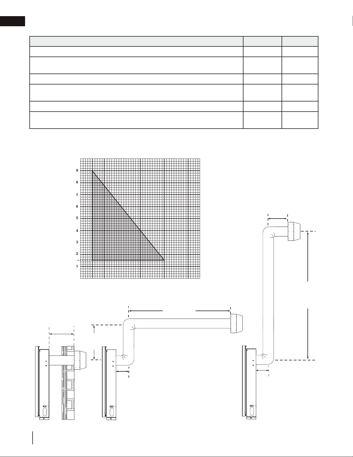
2.4 horizontal termination
MIN MAX
Allowable 3/5 vent connections (excluding appliance and air terminal connections)
Rise per foot (recommended)
Rise per foot (allowable)
Horizontal run (If vent run does not include vertical rise)
Horizontal run (if vent run includes vertical rise)
Vertical run
(* Immediately off the appliance, if 7' (2m) maximum horizontal run is required)
N/A 1
1/4"
(6.4mm)
N/A
0” N/A
4" (102mm)
24"
(610mm)
4" (102mm) 7' (2m)
18"
(457mm)*
7' (2m)
Any offsets other than 2-90° elbows used in the vent run - must be deducted from the maximum horizontal vent
run based upon the offset value.
See graph to determine the required vertical rise VT for the required horizontal rise HT.
10
9
8
7
6
1.5
5
4
3
2
1
(457mm)
REQUIRED
VERTICAL
RISE IN
FEET (V
T)
10
W415-1367 / B / 01.09.19
4" (102mm)
MIN.
24" (610mm)
MAX.
0
1 2 3 4 5 6 7 8 9 10
HORIZONTAL VENT RUN PLUS OFFSET IN FEET (HT)
4"
(102mm)
MIN.
9'
(2.7m)
MAX.
MAXIMUM
VERITICAL
15'
(4.5m)
MAX.
19 1/2'
(6m)
MAX.
24" (610mm)
MIN.
MINIMUM
VERITICAL
MAXIMUM
HORIZONTAL
5' (1.5m) MAX.
15'
(4.5m)
MAX.
MAXIMUM
VERTICAL
19 1/2'
(6m)
MAX.
4"
(102mm)
MIN.
4"
(102mm)
MIN.
MAXIMUM
VERTICAL
19 1/2'
(6m)
MAX.
4"
(102mm)
MIN.
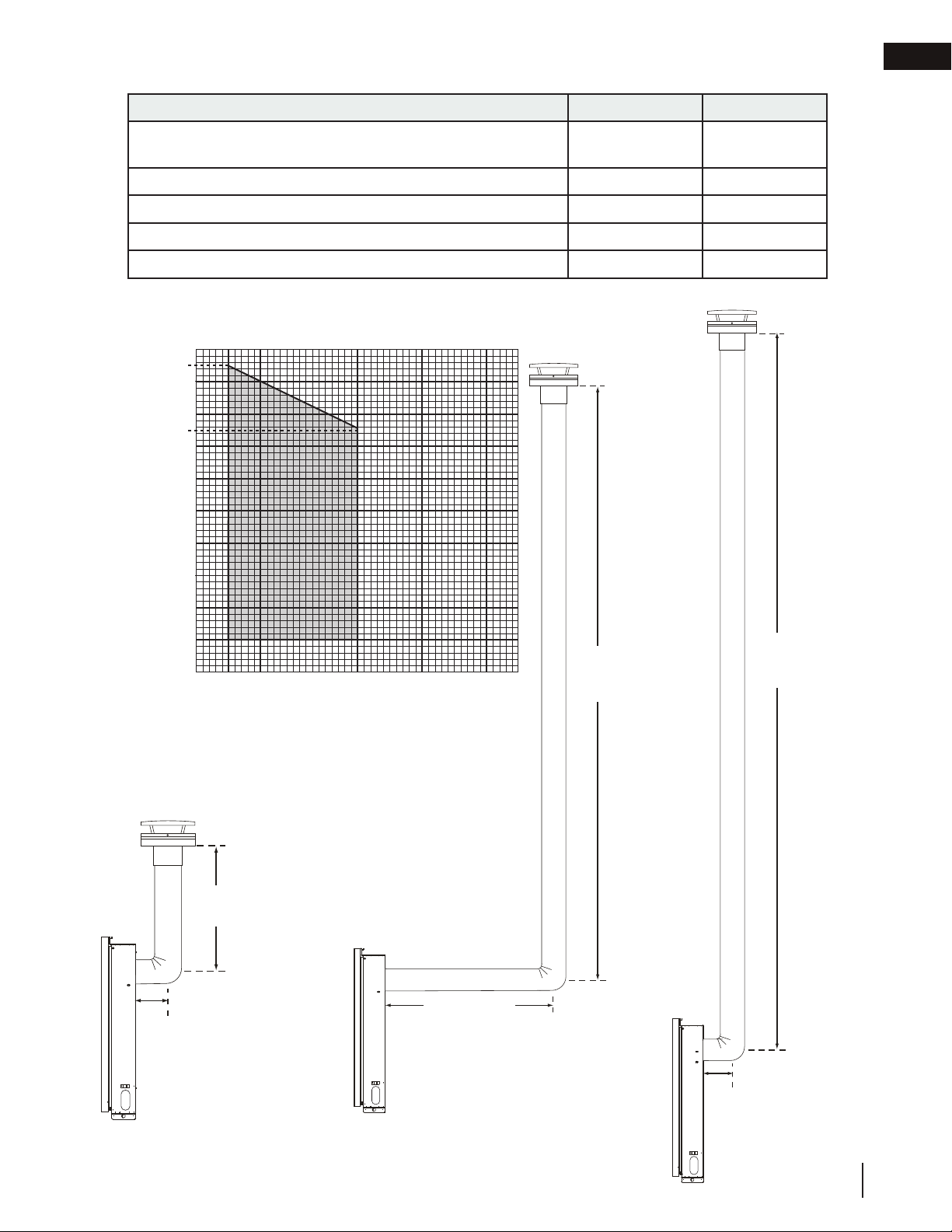
2.5 vertical termination
MIN MAX
venting
EN
Allowable 3/5 vent connections (excluding appliance and air
terminal connections)
Rise per foot (recommended)
Rise per foot (allowable)
Vertical run (when not venting horizontally)
Horizontal run
N/A 2
1/4" (6.3mm) N/A
0" N/A
24" (610mm) 19 1/2' (6m)
4" (102mm) 5' (1.5m)
Any offsets other than 1-90° elbows used in the vent run - must be deducted from the maximum vertical
vent run based upon the offset value.
See graph to determine the required vertical rise VT for the required horizontal rise HT.
20
19.5
18
16
15
14
REQUIRED
VERTICAL
RISE IN
FEET (V
12
10
T)
8
6
4"
(102mm)
MIN.
4
2
0
1 2 3 4 5 6 7 8 9 10
HORIZONTAL VENT RUN PLUS OFFSET IN FEET (HT)
24" (610mm)
MIN.
MINIMUM
VERITICAL
W415-1367 / B / 01.09.19
11

EN
!
WARNING
between the pipe and the fi restop.
WARNING
installation
3.0 installation
• Ensure to unpack all loose materials from inside the fi rebox prior to connecting the gas and electrical supply
• If your appliance is supplied with a remote, ensure the remote receiver is in the “OFF” position prior
to connecting the gas and electrical supply to the appliance.
• For safe and proper operation of the appliance, follow the venting instructions exactly.
• The appliance exhaust fl ue collar must be sealed using Mill Pac. All exhaust and intake vent pipe joints
must be sealed using red RTV high temp silicone sealant (W573-0002) (not supplied) or black high temp Mill
Pac (W573-0007) (not supplied).
• If using pipe clamps to connect rigid vent components, a minimum of 3 screws must also be used to ensure
the connection cannot slip off.
• Do not clamp the fl exible vent pipe.
• Risk of fi re, explosion, or asphyxiation. Improper support of the entire venting system may allow vent to sag
and separate. Use vent run supports and connect vent sections per installation instructions.
• Risk of fi re, do not allow loose materials or insulation to touch the vent pipe. Remove insulation to allow for the
installation of the attic shield and to maintain clearances to combustibles.
• Do not fi ll the space between the vent pipe and enclosure with any type of material. Do not pack insulation
or combustibles between ceiling fi restops. Always maintain specifi ed clearances around venting and fi restop
systems. Install wall shields and fi restops as specifi ed. Failure to keep insulation or other materials away from
vent pipe may cause fi re.
3.1 horizontal installation
!
• The fi restop assembly must be installed with the vent shield to the top.
• Terminals must not be recessed into a wall or siding more than the depth of the return fl ange of the mounting
plate.
This application occurs when venting through an exterior
wall. Having determined the correct height for the air
terminal location, cut and frame a hole in the exterior wall,
as illustrated, to accommodate the fi restop assembly. Dry
fi t the fi restop assembly before proceeding to ensure the
brackets on the rear surface fi t to the inside surface of the
horizontal framing.
The length of the vent shield may be cut shorter for
combustible walls that are less than 8 1/2” (215.9mm)
thick but the vent shield must extend the full depth of the
combustible wall.
note:
Do not fi ll the air space between the fi restop spacer and the
exterior wall with any type of insulating material (i.e. spray foam).
A. Apply a bead of caulking (not supplied) around the outer edge of
the hole of the fi restop assembly, fi t the fi restop assembly to the
hole and secure using 4 screws.
B. Once the vent pipe is installed in its fi nal position, apply red RTV silicone (W573-0002) (not supplied)
CAULKING
FIRESTOP
SPACER
CAULKING
VENT
SHIELD
FINISHING
MATERIAL
note:
The above is for illustration purposes only. Vents
do not always pass through center of frame.
ADD
9”
HEIGHT
(22.9cm)
(20.3cm)
DETERMINE
THE
CORRECT
HEIGHT
8”
ADD
WIDTH
12
W415-1367 / B / 01.09.19
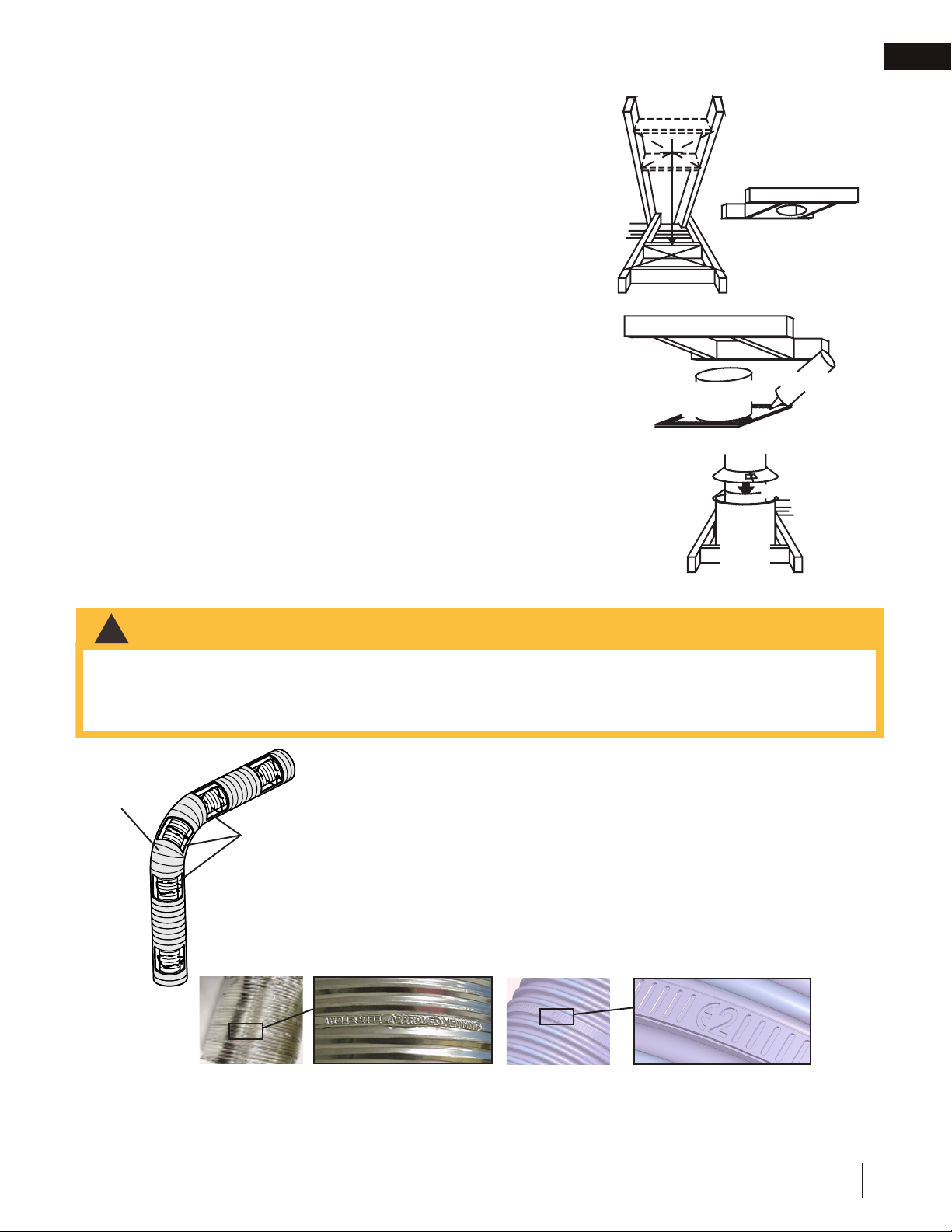
3.2 vertical installation
This application occurs when venting through a roof. Installation kits for
insulation, from fi lling up the 1" (25mm) air space around the pipe.
“Wolf Steel Approved Venting” or “E2” as identifi ed by the stamp only on the fl ex pipes.
!
WARNING
various roof pitches are available from your authorized dealer / distributor.
See the “accessories” section to order specifi c kits required.
A. Determine the air terminal location, cut and frame a square opening,
as illustrated, in the ceiling and the roof to provide the minimum 1"
(25mm) clearance between the vent pipe and any combustible material.
Try to center the vent pipe location midway between two joists to
prevent having to cut them. Use a plumb bob to line up the center of
the openings. A vent pipe shield will prevent any materials such as
insulation, from fi lling up the 1" (25mm) air space around the pipe. Nail
headers between the joist for extra support.
B. Apply a bead of caulking (not supplied) to the framework or to the
Wolf Steel vent pipe shield plate or equivalent (in the case of a fi nished
ceiling), and secure over the opening in the ceiling. A fi restop must be
placed on the bottom of each framed opening in a roof or ceiling that
the venting system passes through. Apply a bead of caulking all around
and place a fi restop spacer over the vent shield to restrict cold air from
being drawn into the room or around the fi replace. Ensure that both
spacer and shield maintain the required clearance to combustibles.
Once the vent pipe is installed in its fi nal position, apply red RTV
silicone (W573-0002) (not supplied) between the pipe and the fi restop
assembly.
C. In the attic, slide the vent pipe collar down to cover up the open end
of the shield and tighten. This will prevent any materials, such as
installation
Vent Pipe
Shield
Vent
Pipe
Shield
EN
Firestop
underside
of joist
Caulking
Vent
Pipe
Collar
3.3 using flexible vent components
• Do not allow the inner fl ex pipe to bunch up on horizontal or vertical runs and elbows. Keep it pulled tight.
• Spacers are attached to the inner fl ex pipe at predetermined intervals to maintain an even air gap to the outer
fl ex pipe. This gap is required for safe operation. A spacer is required at the start, middle, and end of each
elbow to ensure this gap is maintained. These spacers must not be removed.
Elbow
Spacers
For safe and proper operation of the appliance, follow the venting instructions
exactly.
The vent system must be supported approximately every 3 feet (0.9m) for
both vertical and horizontal runs. Use Wolf Steel Ltd. support ring assembly
or equivalent noncombustible strapping to maintain the minimum clearance to
combustibles for both vertical and horizontal runs.
All inner fl ex pipe and outer fl ex pipe joints may be sealed using high temperature
red RTV silicone W573-0002 (not supplied) or the high temperature sealant W5730007 Mill Pac (not supplied). However, the high temperature sealant W573-0007
Mill Pac (not supplied) must be used on the joint connecting the inner fl ex pipe and
the exhaust fl ue collar.
Use only approved fl exible vent pipe kits marked:
W415-1367 / B / 01.09.19
13
EN
Outer Flex
HI-TEMP
SEALANT
installation
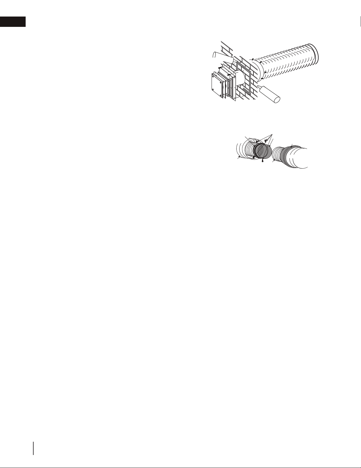
3.3.1 horizontal air terminal installation
A. Stretch the inner flex pipe to the required length taking into
account the additional length needed for the finsihed wall
surface. Slip the vent pipe a minimum of 2" (51mm) over the
inner sleeve of the air terminal and secure with 3#8 screws.
Apply a heavy bead of the Mill Pac sealant (W573-0007)
(not supplied).
B. Using the outer flex pipe, slide over the outer combustion air sleeve
of the air terminal and secure the 3#8 screws. Seal using Red RTV
Silicone (W573-0002) (not supplied).
C. Insert the vent pipes through thee firestop maintaining the required
clearances to combustibles. Holding the sir terminal (lettering in an upright,
readable position), secure to the exterior wall and make
weather tight by sealing with caulking (not supplied).
D. If more vent pipe needs to be used to reach the fireplace,
cople them together as illustrated. The vent system must be
supported approximately every 3 feet (0.9m) for both vertical and
horizontal runs. Use noncombustible strapping to maintain the
minimum clearance to combustibles.
CAULKING
Hi-Temp Sealant
Outer Flex
#10 X 2”
SCREWS
EXTERIOR
WALL
Pipe
OUTER FLEX
PIPE
P
X
E
L
F
NNER
I
1 1/2” (38.1mm)
OVERLAP
HIGH
TEMPERATURE
SEALANT
Screws
Inner Coupler
Outer Coupler
Inner Flex
Pipe
IPE
Pipe
14
W415-1367 / B / 01.09.19
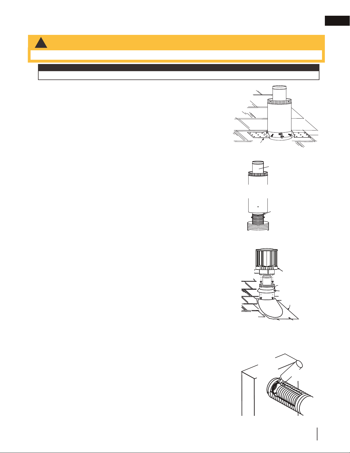
3.3.2 vertical air terminal installation
air terminal installation
!
WARNING
temperature red RTV silicone (W573-0002) (not supplied).
ADD FASTENER TYPE
REAR VENT
1 1/4” (31.8mm)
Overlap
TOP VENT - FLEX TOP VENT - RIGID/FLEX
#8 X 1/2”
Self Drilling
Screws
45 VENT - FLEX 45 VENT - RIGID/FLEX
#8 X 1/2”
Self Drilling
Screws
Mill-Pac Sealant
Red RTV
Silicone
2” (50.8mm)
Overlap
Mill-Pac
Sealant
#8 X 1/2”
Self Drilling
Screws
• Maintain a minimum 2” (51mm) space between the air inlet base and the storm collar.
note:
Fastening hardware provided with appropriate roof terminal and liner kits.
A. Fasten the roof support to the roof using 6 screws. The roof support is
optional. In this case, the venting is to be adequately supported using
either an alternate method suitable to the authority having jurisdiction or
the optional roof support.
B. Stretch the inner fl ex pipe to the required length. Slip the inner fl ex
pipe a minimum of 2” (51mm) over the inner pipe of the air terminal
connector and secure with a minimum of three screws, when 4/7, 5/8
and 3/5 venting is used and a minimum of six screws when using 8/10
or 8/11 venting. Seal using a heavy bead of red RTV silicone sealant
(W573-0002) (not supplied).
C. Repeat using the outer fl ex pipe, using a heavy bead of red RTV
silicone sealant (W573-0002) (not supplied) and a minimum of three
screws, when 4/7, 5/8 and 3/5 venting is used and a minimum of six
screws when using 8/10 or 8/11 venting.
D. Thread the air terminal connector / vent pipe assembly down through
the roof. The air terminal must be positioned vertically and plumb.
Attach the air terminal connector to the roof support, ensuring that the
top of the air terminal is 16” (40.6cm) above the highest point that it
penetrates the roof.
E. Remove nails from the shingles, above and to the sides of the air
terminal connector. Place the fl ashing over the air terminal connector
leaving a min. 3/4” (19mm) of the air terminal connector showing above
the top of the fl ashing. Slide the fl ashing underneath the sides and
upper edge of the shingles. Ensure that the air terminal connector is
properly centered within the fl ashing, giving a 3/4” (19mm) margin all
around. Fasten to the roof. Do not nail through the lower portion of the
fl ashing. Make weather-tight by sealing with caulking. Where possible,
cover the sides and top edges of the fl ashing with roofi ng material.
F. Aligning the seams of the terminal and air terminal connector, place the
terminal over the air terminal connector making sure the vent pipe goes
into the hole in the terminal. Secure with a minimum of three screws,
when 4/7, 5/8 and 3/5 venting is used and a minimum of six screws
when using 8/10 or 8/11 venting.
G. Apply a heavy bead of weatherproof caulking 2” (51mm) above the
fl ashing. Install the storm collar around the air terminal and slide down
to the caulking. Tighten to ensure that a weather-tight seal between the
air terminal and the collar is achieved.
H. If more vent pipe needs to be used to reach the appliance, see “horizontal
” section.
3.3.3 appliance vent connection
A. Install the inner fl ex pipe to the appliance. Secure with a minimum of
three screws when installing 3”/5”, 4”/7” or 5”/8” venting, or six screws
when installing 8”/10” or 8”/11” venting. Seal the joint and screw holes
using Mill Pac sealant (W573-0007) (not supplied).
B. Install the outer fl ex pipe to the appliance. Secure with a minimum of
three screws when installing 3”/5”, 4”/7” or 5”/”8 venting, or six screws
when installing 8”/10” or 8”/11” venting. Seal the joints using high
installation
Roof Support
Inner Pipe
Air
Terminal
Connector
Red RTV
Silicone
(W572-0002)
Inner Flex Pipe
Outer Flex Pipe
2” (51mm)
#8 X 1/2”
Self
Drilling
Screws
INSERT
Air Inlet
Base
Caulking
Sto r m Collar
Weather
Sealant
Flashing
IMAGE HERE
1 1/2”
(38.1mm)
Overlap
Mill Pac
Sealant
EN
W415-1367 / B / 01.09.19
15
EN
!
WARNING
• Check for gas leaks by brushing on a soap and water solution. Do not use open fl ame.
To convert from one gas to another, consult your Authorized dealer/distributor.
installation
3.4 gas installation
• Risk of fi re, explosion, or asphyxiation. Ensure there are no ignition sources such as sparks or open fl ames.
• Support gas control when attaching gas supply pipe to prevent damaging gas line.
• Always light the pilot whether for the fi rst time or if the gas supply has run out with the glass door opened
or removed. Purging of the gas supply line should be performed by a qualifi ed service technician. Ensure
that a continuous gas fl ow is at the burner before closing the door. Ensure adequate ventilation. For gas and
electrical locations, see “dimensions” section.
• All gas connections must be contained within the appliance when complete (gas fi replaces only).
• High pressure will damage valve. Disconnect gas supply piping before testing gas line at test pressures above
1/2 PSIG.
• Valve settings have been factory set, do not change.
Installation and servicing to be done by a qualifi ed installer.
• Move the appliance into position and secure.
• If equipped with a fl ex connector, the appliance is designed to accept a 1/2” (13mm) gas supply. Without the
connector, it is designed to accept a 3/8” (9.5mm) gas supply. The appliance is equipped with a manual shut
off valve to turn off the gas supply to the appliance.
• Connect the gas supply in accordance to local codes. In the absence of local codes, install to the current
CAN/CSA-B149.1 Installation Code in Canada or to the current National Fuel Gas Code, ANSI Z223.1 / NFPA
54 in the United States.
• When fl exing any gas line, support the gas valve so that the lines are not bent or kinked.
• The gas line fl ex-connector should be installed to provide suffi cient movement for shifting the burner assembly
on its side to aid with servicing components.
3.5 mobile home
This appliance must be installed in accordance with the manufacturer’s instructions and the Manufactured
Home Construction and Safety Standard, Title 24 CFR, Part 3280, in the United States or the Mobile Home
Standard, CAN/CSA Z240 MH Series, in Canada. This appliance is only for use with the type(s) of gas
indicated on the rating plate.
This mobile/manufactured home listed appliance comes factory equipped with a means to secure the appliance. Built
in appliances are equipped with 1/4” (6.4mm) diameter holes located in the front left and right corners of the base.
Use appropriate fasteners, inserted through the holes in the base to secure. For free standing products contact your
local authorized dealer / distributor for the appropriate securing kit. For mobile home installations, the appliance must
be fastened in place. It is recommended that the appliance be secured in all installations. Always turn off the pilot and
the fuel supply at the source, prior to moving the mobile home. After moving the mobile home and prior to lighting the
appliance, ensure that the logs are positioned correctly.
This appliance is certifi ed to be installed in an aftermarket permanently located, manufactured (mobile) home,
where not prohibited by local codes.
This appliance is only for use with the type of gas indicated on the rating plate. This appliance is not convertible
for use with other gases, unless a certifi ed kit is used.
Conversion Kits
This appliance is fi eld convertible between Natural Gas (NG) and Propane (P).
16
W415-1367 / B / 01.09.19

4.0 framing
!
WARNING
note:
When using optional fi nishing accessories, the framing dimensions and fi nishing materials may differ from
what is outlined in the section below; refer to the leafl et instructions supplied in the accessory kit for specifi c
framing and fi nishing specifi cations.
• Risk of fi re!
• In order to avoid the possibility of exposed insulation or vapour barrier coming in contact with the appliance
body, it is recommended that the walls of the appliance enclosure be “fi nished” (i.e. drywall / sheetrock),
as you would fi nish any other outside wall of a home. This will ensure that clearance to combustibles is
maintained within the cavity.
• Do not notch the framing around the appliance stand offs. Failure to maintain air space clearance may cause
over heating and fi re. Prevent contact with sagging or loose insulation or framing and other combustible
materials. Block opening into the chase to prevent entry of blown-in insulation. Make sure insulation and
other materials are secured.
• When constructing the enclosure, allow for fi nishing material thickness to maintain clearances. Framing or
fi nishing material closer than the minimums listed must be constructed entirely of non-combustible materials.
Materials consisting entirely of steel, iron, brick, tile, concrete, slate, glass or plasters, or any combination
thereof are suitable. Materials that are reported as passing ASTM E136, standard test method for behaviour
of materials in a vertical tube furnace at 1382ºF (750ºC) and UL763 shall be considered non-combustible
materials.
• Minimum clearance to combusibles must be maintained or a serious fi re hazard could result.
• The appliance requires a minimum enclosure height. Measure from the appliance base.
• If steel stud framing kits with cement board are provided, or specifi ed in the installation instructions, they
must be installed.
• If specifi ed in the installation instruction, fi nishing must be done using a non-combustible board, ceramic tile,
marble, etc. Do NOT use wood or drywall. Any fi re rated drywall is not acceptable.
framing
EN
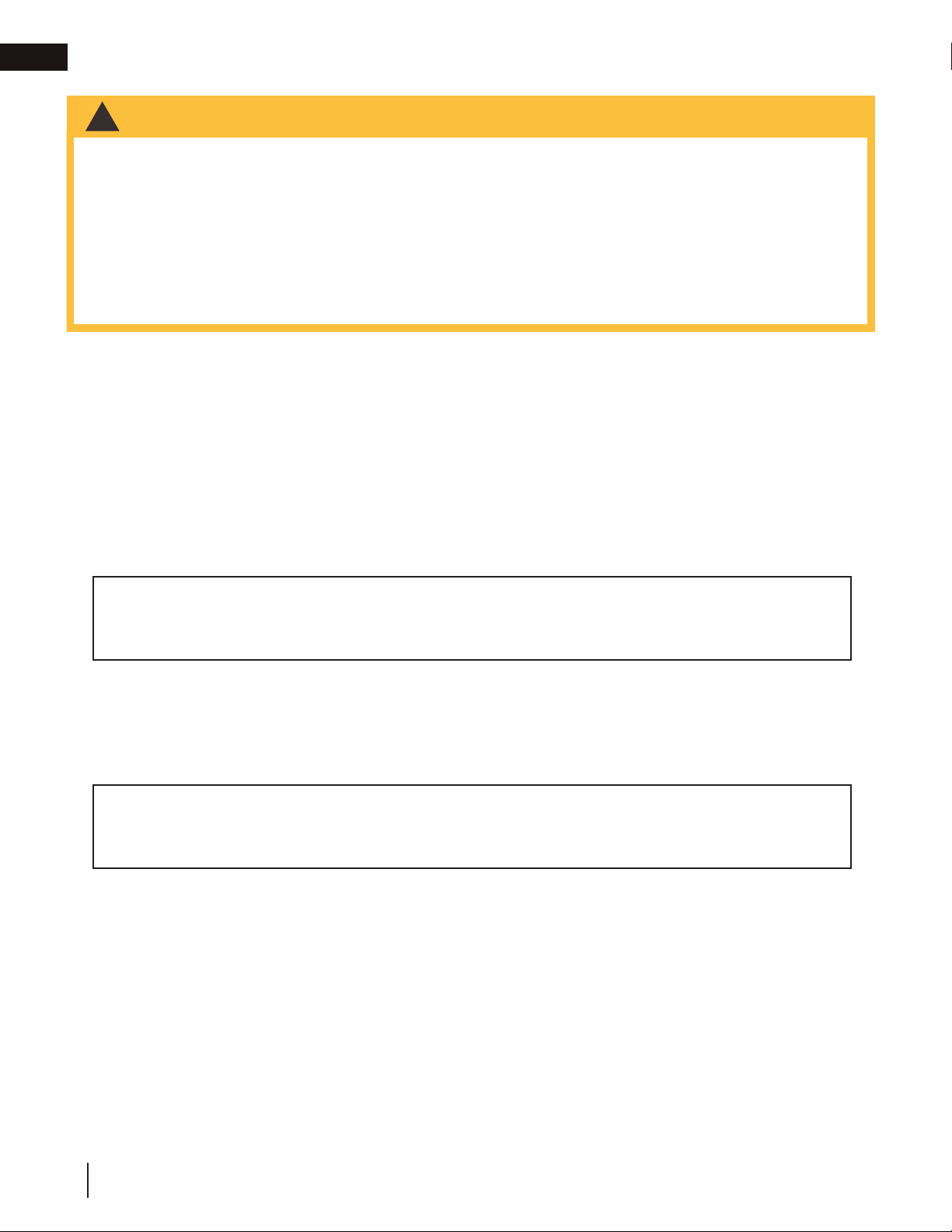
The has been designed to be installed mid-way up a wall. If installing this appliance close to the finished
floor, the appliance must be raised a minimum of 2" (51mm) (unobstructed) to allow for full rotation of the control
door. It is not necessary to install floor protection. Although the appliance fits between studs, most jurisdictions
will not allow a “hole” in the warm air envelope of a residential structure. It is recommended to build either an
interior or exterior chase with a minimum depth of 7" (178mm).
It is best to frame your appliance after it is positioned and the vent system is installed. Frame to local building
codes.
To install the appliance face flush with the finished surface, position the framework to accommodate the thickness
of the finished surface. Use 4 flat-head screws to secure the nailing tabs to the framing. Cover the nailing tabs
with your finishing material.
W415-1367 / B / 01.09.19
17
EN
2" (51mm)
MIN.*
12" (305mm)
MIN. TO
COMBUSTIBLES
(to ceiling or mantle)
1
1
/2" (38mm)
MIN.
material installed in this
space (ie. baseboards)
control door.
COMBUSTIBLE
NON-COMBUSTIBLE
1" (25mm)
1" (25mm)
0” IF
NON-COMBUSTIBLE
FINISHING IS USED
SUCH AS BRICK AND
STONE.
BRICK
6" (152mm)
MIN.
framing
4.1 minimum clearance to combustibles
Minimum clearance to combustible construction from appliance and vent surfaces:
Appliance framing: - 6" (152mm) to top
- 0" to stand-offs
(Rear and sides)
Vent pipe*: - 2" (51mm) top
- 1" (25mm) sides and bottom
Recessed depth: - 7" (178mm)
* HORIZONTAL VENT SECTIONS: A minimum clearance of 1" (25mm) at the bottom and sides and 2" (51mm)
at the top of the vent pipe in all horizontal runs to combustibles is required. Use firestop spacer W010-1961
(supplied).
* VERTICAL VENT SECTIONS: A minimum of 1" (25mm) all around the vent pipe on all vertical runs to
combustibles is required. Use firestop spacer W500-0358 (not supplied).
COMBUSTIBLE
NON-COMBUSTIBLE
(to ceiling or mantle)
* Any protruding finishing
material installed in this
space (ie. baseboards)
must leave 2" (51mm) of
unobstructed clearance to
allow for full rotation of the
12" (305mm)
MIN. TO
COMBUSTIBLES
control door.
2" (51mm)
MIN.*
BRICK
6" (152mm)
MIN.
1" (25mm)
1" (25mm)
1
/2" (38mm)
1
MIN.
FRAME
0” IF
NON-COMBUSTIBLE
FINISHING IS USED
SUCH AS BRICK AND
STONE.
CONTROL DOOR
(OPEN POSITION)
18
WITHOUT FRAME INSTALLED
W415-1367 / B / 01.09.19
WITH FRAME INSTALLED

4.2 minimum enclosure clearances
INTERIOR BUILT-OUT
framing
EN
21 1/4"
540mm
368mm
762mm
14 1/2"
30"
OUTSIDE
CHASE
INSIDE
CHASE
14 1/2"
368mm
EXTERIOR CHASE
14 1/2"
368mm
PROTRUSION
2"
51mm
4"
102mm
6"
152mm
7"
178mm
7"
178mm
2"
51mm
4"
SIDE
WALL
102mm
7"
(178mm)
44 1/4"
(1124mm)
14 1/2"
(368mm)
TM
RCH
O
T
TM
CH
R
O
T
11 5/8"
(295mm)
34 7/8"
(886mm)
1 2 3
FRAMING
OPENING DIMENSIONS
NOTE: Finished opening is smaller than the framed opening. We recommend installing The
Torch™ in the centre of the wall so that it is at eye level.
INSTALLATION
FINISHING
OPENING DIMENSIONS
W415-1367 / B / 01.09.19
19
EN
W385-0380
1
2
2
framing
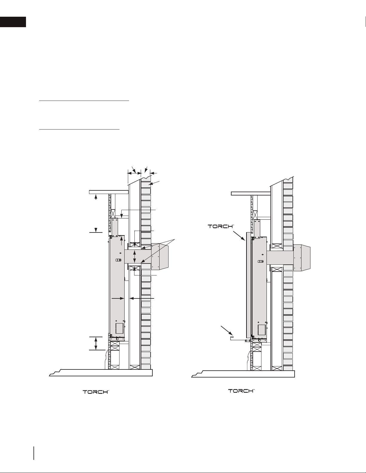
4.3 nailing tab installation
Attach the 4 nailing tabs supplied to the sides of the
outer shell as illustrated using the 8 self-tapping screws
included in the manual baggie.
4.4 stand-off assembly
20
W415-1367 / B / 01.09.19
5.0 finishing
WARNING
finishing
!
• Risk of fi re!
• Never obstruct the front opening of the appliance.
• The front of the appliance must be fi nished with any non-combustible materials such as brick, marble, granite,
etc., provided that these materials do not go below the specifi ed dimension, as illustrated.
• Do not strike, slam, or scratch. Do not operate appliance with glass removed, cracked, or scratched.
• Facing and/or fi nishing material must never overhang into the appliance opening.
• The glass door assembly is a safety device designed to pivot forward when relieving excess pressure that
might occur. Finishing or other materials must not be located in the opening surrounding the door as this will
interfere with the doors ability to relieve pressure.
• If applicable, drywall dust will penetrate into the blower bearings, causing irreparable damage. Care must
be taken to prevent drywall dust from coming into contact with the blower or its compartment. Any damage
resulting from this condition is not covered by the warranty policy.
5.1 mounting cabinet installation
WARNING
!
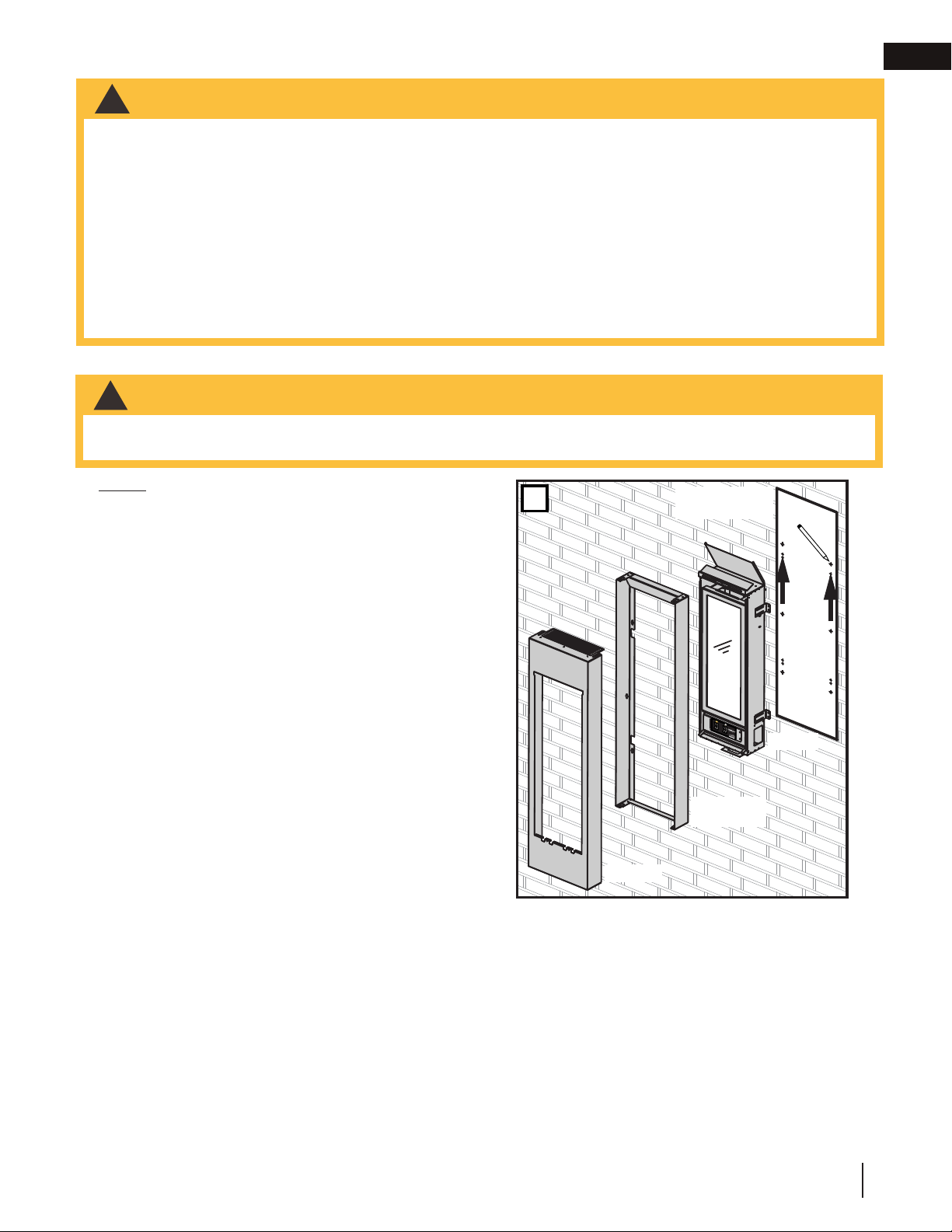
• Before starting the installation, remove the protective layer from all three components that make up the GT8
(cabinet, frame and torch).
EN
NOTE: It is recommended that all fasteners be stainless
steel.
A. Using the installation template (W122-0401) supplied
with the TMCK or TMCSS kit, determine the best
mounting location for your new Torch. See “minimum
clearance to combustibles” section. Mark all 14 hole
centres on the wall (surface) using the template.
1
INSTALLATION
TEMPLATE
TORCH
MOUNTING
FRAME
CABINET
W415-1367 / B / 01.09.19
21
EN
INSTALLATION
TEMPLATE
TORCH
MOUNTING
FRAME
CABINET
1
finishing
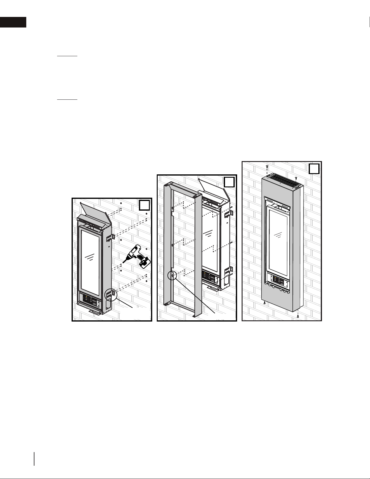
B. Remove the template. Depending on the surface and fasteners, drill the appropriate holes. Hold the
Torch up, aligning the mounting brackets to the mounting holes. Secure the Torch to the wall using the
appropriate fasteners.
NOTE: The Torch has been designed to have a 1/2" (13mm) clearance between the rear outer
panel and the mounting surface.
C. Start the fasteners into each of the six remaining mounting holes. Align the keyholes of the frame to the
heads of the fasteners and slide the frame down onto the fasteners. Ensure the frame is plumb and level
before tightening the fasteners.
NOTE: It is recommended that the gas and electrical be connected to the appliance at this
stage. Both must enter the appliance at the opening created between the bottom of the Torch
and the bottom of the mounting frame.
D. Slide the front of the cabinet over the mounting frame, ensuring the “mesh” is to the top. Start each of the
four screws (supplied) through the slots. Once the cabinet has been adjusted for depth the four screws
can be tightened.
3
4
2
MOUNTING
BRACKET
KEYHOLE
22
W415-1367 / B / 01.09.19

finishing
!
WARNING
5.2 safety barrier installation and removal
• Glass may be hot. Do not touch glass until cooled.
• If equipped with door latches that are part of a safety system, they must be properly engaged. Do not
operate the appliance with latches disengaged.
• Facing and/or fi nishing materials must not interfere with air fl ow through air openings, louvre openings,
operation of louvres, or doors/access for service. Observe all clearances when applying combustible
materials.
• Before door is removed, turn the appliance off and wait until appliance is cool to the touch. Doors are heavy
and fragile so handle with care.
A barrier designed to reduce the risk of burns from the hot viewing glass is provided with the appliance
and must be installed.
Before the glass door can be removed, the front frame and safety screen must be removed. Lift the front frame
up and away from the appliance. Remove the two side screws securing the safety screen. Lift and tilt the bottom
forward and remove from the appliance.
EN
SAFETY
SCREEN
SAFETY
SCREEN
SAFETY
SCREEN
W415-1367 / B / 01.09.19
23
EN
!
WARNING
finishing
5.3 door removal
• Glass may be hot. Do not touch glass until cooled.
• If equipped with door latches that are part of a safety system, they must be properly engaged. Do not
operate the appliance with latches disengaged.
• Facing and/or fi nishing materials must not interfere with air fl ow through air openings, louvre openings,
operation of louvres, or doors/access for service. Observe all clearances when applying combustible
materials.
• Before door is removed, turn the appliance off and wait until appliance is cool to the touch. Doors are heavy
and fragile so handle with care.
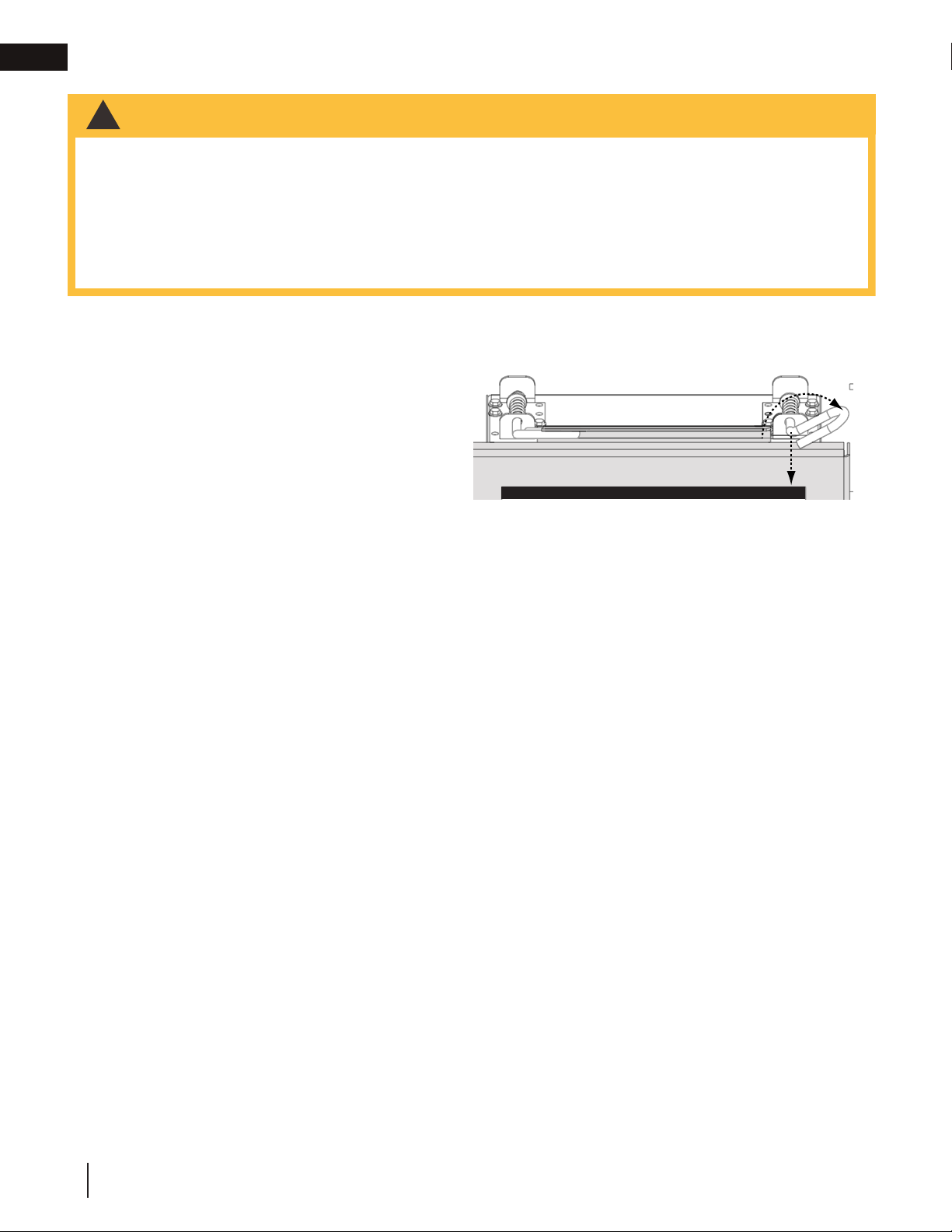
Before the glass door can be removed, the optional frame/front must be
removed.
The glass door is secured to the top front edge of the
firebox. Pull the handles of the latches forward, then lift
the hooks out from the slots in the door frame to release
the top of the door. Then, pivot forward until the top
edge of the door clears the front of the appliance. Next
gripping the sides of the door lift the door out from the
retainer along the bottom of the door.
Reverse these steps to re-install the screen and door.
Ensure safety screen is installed correctly.
CLOSED
OPEN
24
W415-1367 / B / 01.09.19

finishing
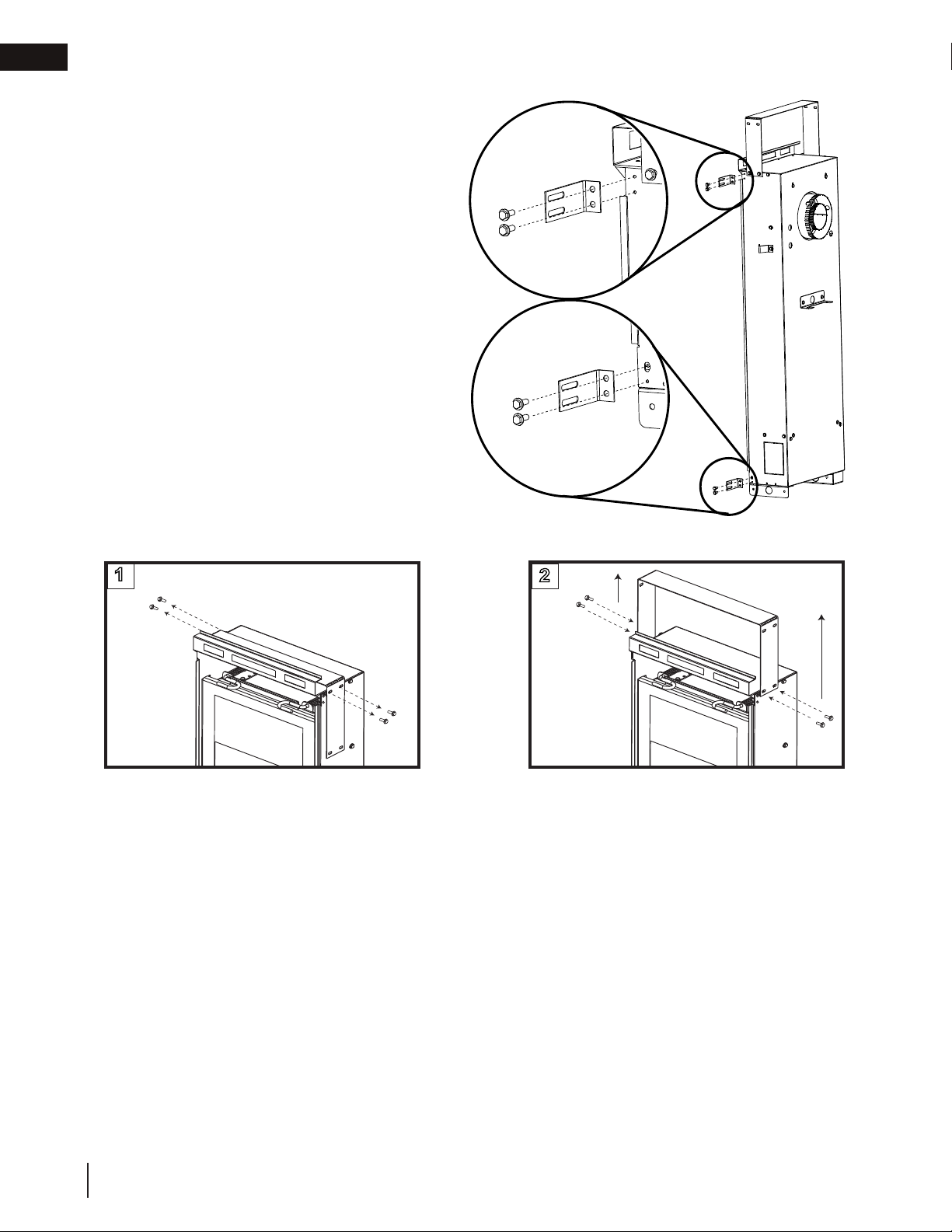
5.4 frame/front installation
A. Align the two holes in the upper portion
of the hinge on the control door to those
in the bottom trim bracket, secure using
two of the #8 x 1/2" hex head screws
supplied.
B. Install the top trim bracket to the firebox
using the three #9 - 14 x 1/2" hex head
screws supplied in the manual
baggie.
C. Rest the top lip of the frame on
the top trim bracket, and the securing tabs at the bottom of the frame on the bottom trim bracket.
D. Align the two slots in the top of the frame with the two holes in the top trim bracket and secure
using the two #10 pan head screws supplied however do not fully tighten to leave room for adjustment.
E. Align the holes in the securing tabs at the bottom of the frame with the holes in the bottom trim
bracket and secure using the two remaining #8 x 1/2" hex
head screws, however do not fully tighten to leave room for
adjustment.
F. If required, the bottom trim bracket can be adjusted by
loosening it’s securing screws.
G. Once the frame is perfectly square and the control
door will close without rubbing against the sides of the
frame, tighten all screws.
H. Open the control door.
I. Insert the door stop chain into the receiving slot in the control
door.
J. Insert the door stop chain into the receiving slot in the
frame so that when fully open the control door has a
clearance of 1/8" to the finished wall. NOTE: In most cases,
a count of 9 balls between receiving slots will give the
desired clearance.
K. Close the control door.
CONTROL
DOOR
TOP
TRIM
BRACKET
BOTTOM
TRIM
BRACKET
TOP
TRIM
BRACKET
EN
The frame has been designed to accommodate finished
material thicknesses of 1/2" - 3/4" (13mm - 19mm). If it is necessary
to pull the frame out to the max. 3/4" (19mm) the magnetic
catch will need to be adjusted. Minor adjustment can be made by
removing shims from behind the magnet. Major adjustments can be
made by moving the magnet to the outside of the panel.
Adjustment may be required to accommodate the door stop chain
slack when the control door is closed. The control door securing
screws can be loosened to allow adjustment. Before re-tightening
the screws ensure the control door is still recessed into the
frame at a
similar offset to the
top trim piece.
BOTTOM
TRIM
BRACKET
W415-1367 / B / 01.09.19
25
EN
!
WARNING
finishing
5.5 glass media installation
• Clean the glass media prior to installation. Before applying the cleaned glass, ensure that it is dry.
• Do not change or substitute the glass media material provided with this appliance. If replacing, use only the
replacement glass media available from your local authorized dealer / distributor.
• Glass media over the burner must not be more than one layer high. More than one layer over the burner will
cause fl ame lifting and sooting problems.
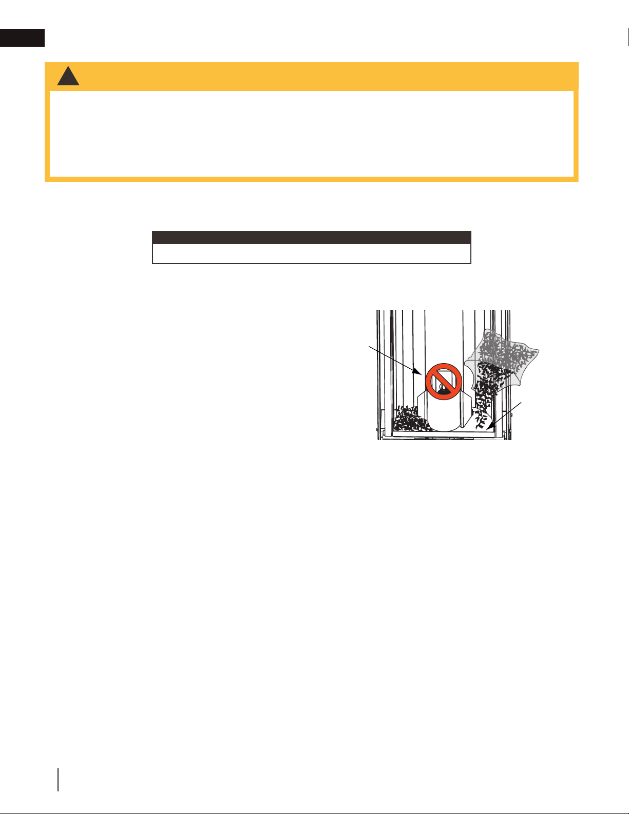
• Do not place any media (glass or vermiculite) in or around the pilot opening and/or on the burner ports. This
will interfere with the pilot operation.
Evenly spread the glass media onto the media tray, covering the burner tube and tray. Ensure no glass
media falls into the pilot opening. If this happens, insert a clean bag into your vacuum cleaner and vacuum
out the glass media. Replacement glass can be purchased from your local dealer / distributor.
note:
Do not use more media than what was supplied with the appliance.
Cleaning Glass Media
Glass media may have a fi ne oil residue that needs to be cleaned prior to installation. Clean the glass with
mild dish soap, drain, rinse thoroughly and dry before placing over the burner.
BURNER
ACCENT
GLASS
GLASS
MEDIA
TRAY
26
W415-1367 / B / 01.09.19
 Loading...