

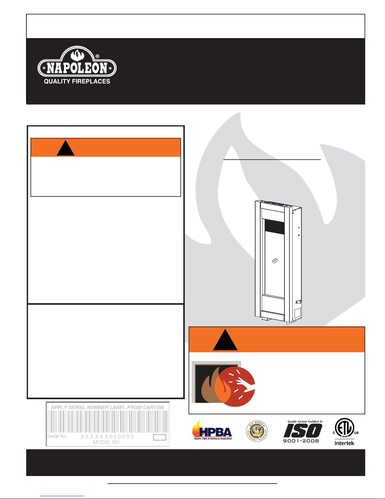
Napoleon GT8N, GT8P Installation And Operating Instructions Manual
INSTALLER: LEAVE THIS MANUAL WITH THE APPLIANCE.
CONSUMER: RETAIN THIS MANUAL FOR FUTURE REFERENCE.
INSTALLATION AND
OPERATING INSTRUCTIONS
CERTIFIED UNDER CANADIAN AND AMERICAN NATIONAL STANDARDS: CSA 2.22, ANSI Z21.50 FOR VENTED GAS FIREPLACE.
CERTIFIED FOR CANADA AND UNITED STATES USING ANSI/CSA METHODS.
1
SAFETY INFORMATION
!
WARNING
If the information in these instructions
are not followed exactly, a fi re or
explosion may result causing property
damage, personal injury or loss of life.
- Do not store or use gasoline or other fl ammable
vapors and liquids in the vicinity of this or any
other appliance.
- WHAT TO DO IF YOU SMELL GAS:
• Do not try to light any appliance.
• Do not touch any electrical switch; do not use
any phone in your building.
• Immediately call your gas supplier from a
neighbour’s phone. Follow the gas supplier’s
instructions.
• If you cannot reach your gas supplier, call the
fi re department.
- Installation and service must be performed by a
qualifi ed installer, service agency or the supplier.
This appliance may be installed as an OEM
installation in manufactured home (USA only) or
mobile home and must be installed in accordance
with the manufacturer’s instructions and the
Manufactured Home Construction and Safety
Standard, Title 24 CFR, Part 3280, in the United
States or the Standard for Installation in Mobile
Homes, CAN/CSA Z240 MH, in Canada.
This appliance is only for use with the type(s) of
gas indicated on the rating plate. A conversion kit
is supplied with the appliance.
!
GT8N
NATURAL GAS
GT8P
PROPANE
WARNING
HOT GLASS WILL CAUSE
BURNS.
DO NOT TOUCH GLASS UNTIL
COOLED.
NEVER ALLOW CHILDREN TO
TOUCH GLASS.
Wolf Steel Ltd., 24 Napoleon Rd., Barrie, ON, L4M 0G8 Canada /
103 Miller Drive, Crittenden, Kentucky, USA, 41030
Phone (705)721-1212 • Fax (705)722-6031 • www.napoleonfi replaces.com • ask@napoleonproducts.com
$10.00
1.28A
W415-0794 / D / 05.30.11

2
TABLE OF CONTENTS
1.0 INSTALLATION OVERVIEW 3
2.0 INTRODUCTION 4
2.1 DIMENSIONS 5
2.2 GENERAL INSTRUCTIONS 5
2.3 GENERAL INFORMATION 6
2.4 RATING PLATE INFORMATION 7
3.0 VENTING 8
3.1 COLD CLIMATE 8
3.2 VENTING LENGTHS AND COMPONENTS 9
3.3 VENT TERMINAL CLEARANCES 10
3.4 HORIZONTAL TERMINATION 11
3.5 VERTICAL TERMINATION 12
4.0 INSTALLATION 13
4.1 WALL AND CEILING PROTECTION 13
4.2 HORIZONTAL INSTALLATION 14
4.3 VERTICAL INSTALLATION 14
4.4 USING FLEXIBLE VENT COMPONENTS 15
4.4.1 HORIZONTAL AIR TERMINAL INSTALLATION 15
4.4.2 VERTICAL AIR TERMINAL INSTALLATION 16
4.4.3 APPLIANCE VENT CONNECTION 17
4.5 GAS INSTALLATION 17
4.6 MOBILE HOME 18
5.0 FRAMING 19
5.1 MINIMUM CLEARANCE TO COMBUSTIBLES 20
5.2 MINIMUM ENCLOSURE CLEARANCES 21
5.3 NAILING TAB INSTALLATION 22
5.4 STAND-OFF ASSEMBLY 22
6.0 FINISHING 23
6.1 MOUNTING CABINET INSTALLATION 23
6.2 DOOR REMOVAL 25
6.3 FRAME/FRONT INSTALLATION 26
6.4 GLASS MEDIA INSTALLATION 27
6.5 LK8 LIGHT INSTALLATION (OPTIONAL) 28
7.0 ELECTRICAL INFORMATION 29
7.1 HARD WIRING CONNECTION 29
8.0 OPERATION 30
9.0 ADJUSTMENTS 31
9.1 GAS PRESSURE ADJUSTMENT 31
9.2 VENTURI ADJUSTMENT 31
9.3 FLAME CHARACTERISTICS 31
10.0 MAINTENANCE 32
10.1 CARE OF GLASS 32
10.2 DOOR GLASS REPLACEMENT 33
11.0 REPLACEMENTS 34
12.0 TROUBLE SHOOTING 37
13.0 WARRANTY 39
14.0 SERVICE HISTORY 40
NOTE: Changes, other than editorial, are denoted by a line in the margin.
W415-0794 / D / 05.30.11

1.0 INSTALLATION OVERVIEW
Door, see “DOOR
REMOVAL / INSTALLATION”
section.
3
Cabinet, see “MOUNTING
CABINET INSTALLATION”
section.
Glass, see “GLASS
REMOVAL / INSTALLATION”
section.
Frame, see “FRAME /
FRONT INSTALLATION”
section.
Rating plate, see “RATING PLATE
INFORMATION” section.
W415-0794 / D / 05.30.11
4
2.0 INTRODUCTION
• THIS APPLIANCE IS HOT WHEN OPERATED AND CAN CAUSE SEVERE BURNS IF CONTACTED.
• ANY CHANGES TO THIS APPLIANCE OR IT’S CONTROLS CAN BE DANGEROUS AND IS PROHIBITED.
• Do not operate appliance before reading and understanding operating instructions. Failure to operate appliance
according to operating instructions could cause fi re or injury.
• Risk of fi re or asphyxiation do not operate appliance with fi xed glass removed.
• Do not connect 110 volts to the control valve.
• Risk of burns. The appliance should be turned off and cooled before servicing.
• Do not install damaged, incomplete or substitute components.
• Risk of cuts and abrasions. Wear protective gloves and safety glasses during installation. Sheet metal edges may be
sharp.
• Do not burn wood or other materials in this appliance.
• Children and adults should be alerted to the hazards of high surface temperature and should stay away to avoid burns or
clothing ignition.
• Young children should be carefully supervised when they are in the same room as the appliance.
young children and others may be susceptible to accidental contact burns. A physical barrier is recommended if there
are at risk individuals in the house. To restrict access to an appliance or stove, install an adjustable safety gate to keep
toddlers, young children and other at risk individuals out of the room and away from hot surfaces.
• Clothing or other fl ammable material should not be placed on or near the appliance.
• Due to high temperatures, the appliance should be located out of traffi c and away from furniture and draperies.
• Ensure you have incorporated adequate safety measure to protect infants/toddlers from touching hot surfaces.
• Even after the appliance is out, the glass and/or screen will remain hot for an extended period of time.
• Check with your local hearth specialty dealer for safety screens and hearth guards to protect children from hot surfaces.
These screens and guards must be fastened to the fl oor.
• Any safety screen or guard removed for servicing must be replaced prior to operating the appliance.
• The appliance is a vented gas-fi red appliance. Do not burn wood or other materials in the appliance.
• It is imperative that the control compartments, burners and circulating blower and its passageway in the appliance
and venting system are kept clean. The appliance and its venting system should be inspected before use and at least
annually by a qualifi ed service person. More frequent cleaning may be required due to excessive lint from carpeting,
bedding material, etc. The appliance area must be kept clear and free from combustible materials, gasoline and other
fl ammable vapors and liquids.
• Under no circumstances should this appliance be modifi ed.
• This appliance must not be connected to a chimney fl ue pipe serving a separate solid fuel burning appliance.
• Do not use this appliance if any part has been under water. Immediately call a qualifi ed service technician to inspect the
appliance and to replace any part of the control system and any gas control which has been under water.
• Do not operate the appliance with the glass door removed, cracked or broken. Replacement of the glass should be done
by a licensed or qualifi ed service person.
• Do not strike or slam shut the appliance glass door.
• When equipped with pressure relief doors, they must be kept closed while the appliance is operating to prevent exhaust
fumes containing carbon monoxide, from entering into the home. Temperatures of the exhaust escaping through these
openings can also cause the surrounding combustible materials to overheat and catch fi re.Only doors / optional fronts
certifi ed with the unit are to be installed on the appliance.
• Only doors / optional fronts certifi ed with the unit are to be installed on the appliance.
• Keep the packaging material out of reach of children and dispose of the material in a safe manner. As with all plastic
bags, these are not toys and should be kept away from children and infants.
• As with any combustion appliance, we recommend having your appliance regularly inspected and serviced as well as
having a Carbon Monoxide Detector installed in the same area to defend you and your family against Carbon Monoxide.
• Ensure clearances to combustibles are maintained when building a mantel or shelves above the appliance. Elevated
temperatures on the wall or in the air above the appliance can cause melting, discolouration or damage to decorations, a
T.V. or other electronic components.
• This appliance uses and requires a fast acting thermocouple. Replace only with a fast acting thermocouple supplied by
Wolf Steel Ltd.
!
WARNING
Toddlers,
3.1C
W415-0794 / D / 05.30.11
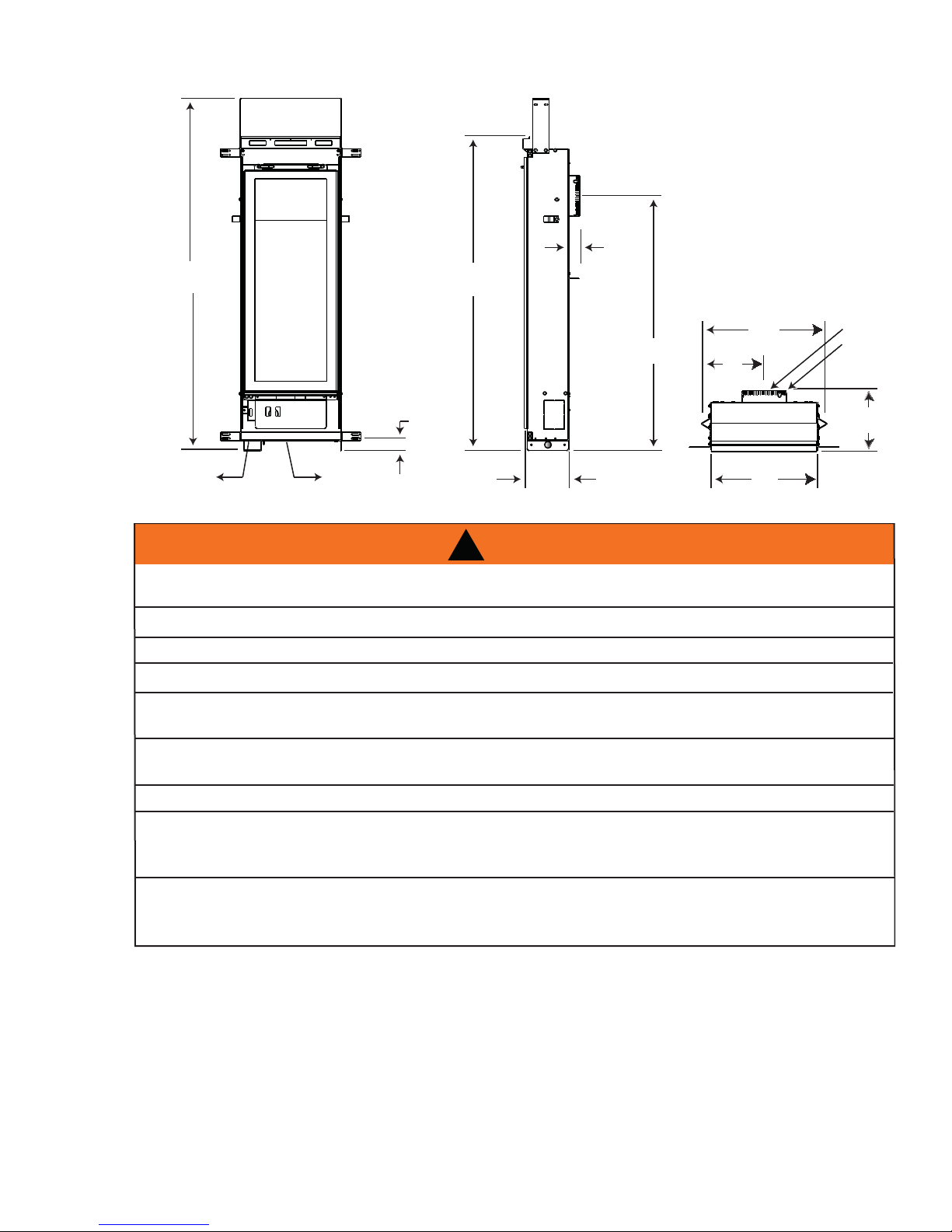
2.1 DIMENSIONS
1
5
1
/4”
43 3/4”
ELECTRICAL
ACCESS
GAS LINE
ACCESS
2.2 GENERAL INSTRUCTIONS
ALWAYS LIGHT THE PILOT WHETHER FOR THE FIRST TIME OR IF THE GAS SUPPLY HAS RUN OUT,
WITH THE GLASS DOOR OPENED OR REMOVED.
PROVIDE ADEQUATE CLEARANCE FOR SERVICING AND OPERATING THE APPLIANCE.
NEVER OBSTRUCT THE FRONT OPENING OF THE APPLIANCE.
OBJECTS PLACED IN FRONT OF THE APPLIANCE MUST BE KEPT A MINIMUM OF 48” FROM THE
37 3/4”
30
1 1/4”
1
5
/2”
!
WARNING
PROVIDE ADEQUA TE VENTILA TION.
FRONT FACE OF THE UNIT.
14”
11
/16”
7”
12”
3” DIA.
5” DIA.
3
/4”
6
SURFACES AROUND AND ESPECIALLY ABOVE THE APPLIANCE CAN BECOME HOT. AVOID CONTACT
HIGH PRESSURE WILL DAMAGE VALVE. DISCONNECT GAS SUPPLY PIPING BEFORE PRESSURE TESTING GAS
LINE AT TEST PRESSURES ABOVE 1/2 PSIG. CLOSE THE MANUAL SHUT-OFF VALVE BEFORE PRESSURE
TESTING GAS LINE AT TEST PRESSURES EQUAL TO OR LESS THAN 1/2 PSIG.
USE ONLY WOLF STEEL APPROVED OPTIONAL ACCESSORIES AND REPLACEMENT PARTS WITH THIS APPLIANCE.
USING NON-LISTED ACCESSORIES (BLOWERS, DOORS, LOUVRES, TRIMS, GAS COMPONENTS, VENTING
COMPONENTS, ETC.) COULD RESULT IN A SAFETY HAZARD AND WILL VOID THE WARRANTY AND CERTIFICATION.
THIS GAS APPLIANCE SHOULD BE INSTALLED AND SERVICED BY A QUALIFIED INSTALLER to
conform with local codes. Installation practices vary from region to region and it is important to know the
specifi cs that apply to your area, for example in Massachusetts State:
• This product must be installed by a licensed plumber or gas fi tter when installed within the commonwealth
of Massachusetts.
• The appliance damper must be removed or welded in the open position prior to installation of a appliance
insert or gas log.
• The appliance off valve must be a “T” handle gas cock.
• The fl exible connector must not be longer than 36 inches.
• A Carbon Monoxide detector is required in all rooms containing gas fi red appliances.
• The appliance is not approved for installation in a bedroom or bathroom unless the unit is a direct vent
sealed combustion product.
WHEN THE APPLIANCE IS OPERATING.
FIRE RISK. EXPLOSION HAZARD.
W415-0794 / D / 05.30.11
6
A
A
The installation must conform with local codes or, in
absence of local codes, the National Gas and Propane
Installation Code CSA B149.1 in Canada, or the National
Fuel Gas Code, ANSI Z223.1 / NFPA 54 in the United
States. Suitable for mobile home installation if installed in
accordance with the current standard CAN/CSA Z240MH
Series, for gas equipped mobile homes, in Canada or
NSI Z223.1 and NFPA 54 in the United States.
s long as the required clearance to combustibles is
maintained, the most desirable and benefi cial location for an appliance is in the center of a building, thereby
allowing the most effi cient use of the heat created. The location of windows, doors and the traffi c fl ow in the
room where the appliance is to be located should be considered. If possible, you should choose a location
where the vent will pass through the house without cutting a fl oor or roof joist.
If the appliance is installed directly on carpeting, vinyl tile or other combustible material other than wood
fl ooring, the appliance shall be installed on a metal or wood panel extending the full width and depth.
Some appliances have optional fans or blowers. If an optional fan or blower is installed, the junction box must
be electrically connected and grounded in accordance with local codes, use the current CSA C22.1 Canadian
Electrical Code in Canada or the ANSI/NFPA 70 National Electrical code in the United States.
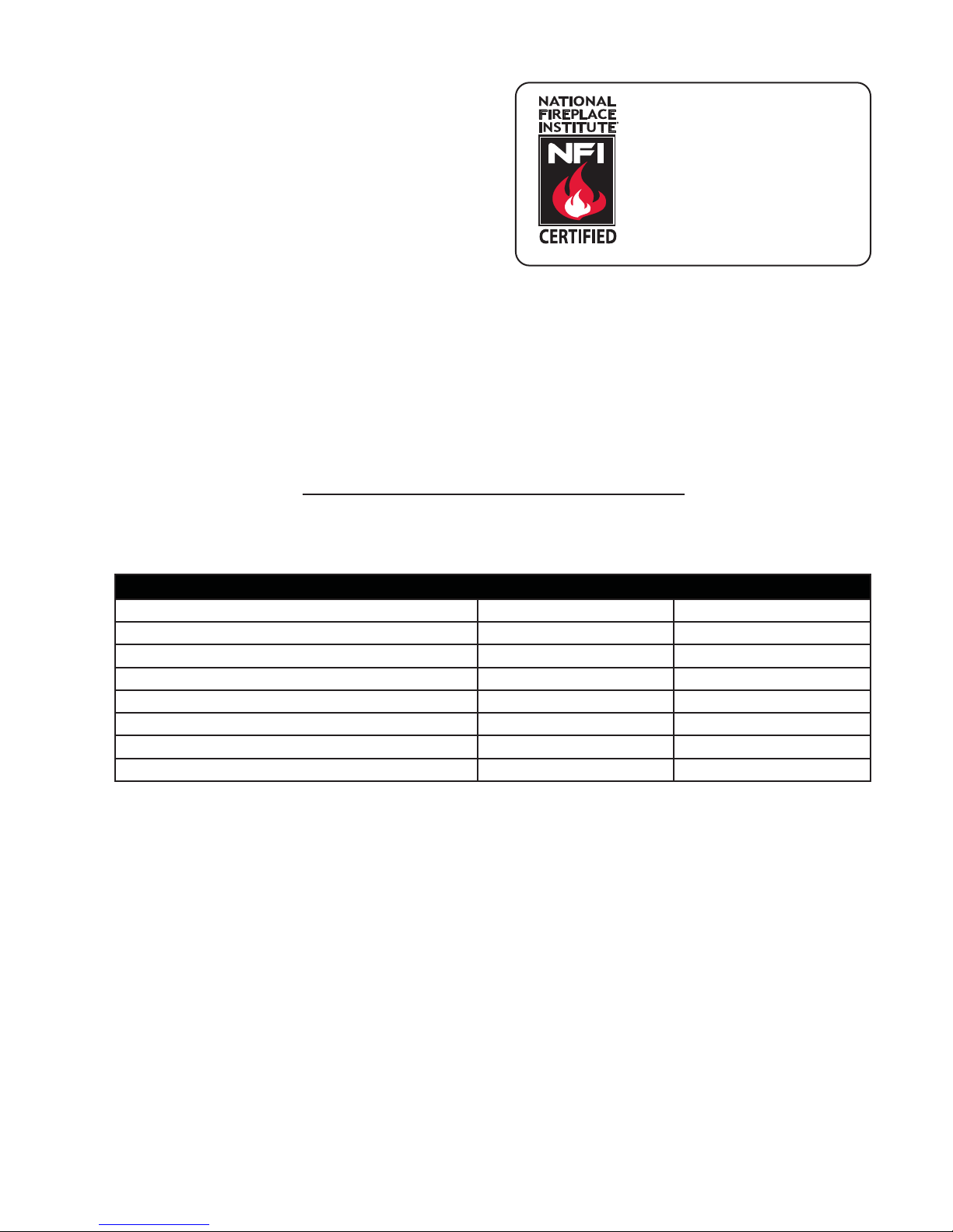
2.3 GENERAL INFORMATION
FOR YOUR SATISFACTION, THIS APPLIANCE HAS BEEN TEST-FIRED TO ASSURE ITS OPERATION
AND QUALITY!
www.ncertied.org
We suggest that our gas
hearth products be installed
and serviced by professionals
who are certied in the U.S.
by the National Fireplace
®
Institute
(NFI) as NFI Gas
Specialists
4.1A
RATES AND EFFICIENCIES
NATURAL GAS PROPANE GAS
Altitude 0 - 4,500* 0 - 4,500*
Maximum Input 6,000 6,000
Maximum Output 4,680 4,680
Effi ciency 78% 78%
Minimum Inlet Gas Supply Pressure 4.5” Water Column 11” Water Column
Maximum Inlet Gas Supply Pressure 7” Water Column 13” Water Column
Manifold Pressure Under Flow Conditions 3.5” Water Column 10” Water Column
* When the appliance is installed at elevations above 4,500ft, and in the absence of specifi c recommendations
from the local authority having jurisdiction, the certifi ed high altitude input rating shall be reduced at the rate of
4% for each additional 1,000ft.
This appliance is approved for bathroom, bedroom and bed-sitting room installations and is suitable for mobile
home installation. The natural gas model can only be installed in a mobile home that is permanently positioned
on its site and fueled with natural gas. This appliance may be installed in an aftermarket permanently located,
manufactured (mobile) home, where not prohibited by local codes.
This appliance is only for use with the type of gas indicated on the rating plate. This appliance is not convertible for use with other gases, unless a certifi ed kit is used.
Expansion / contraction noises during heating up and cooling down cycles are normal and are to be expected.
W415-0794 / D / 05.30.11
2.4 RATING PLATE INFORMATION
UNITED STA TES THE MA
8P
N N
”72”2”
BOTTOM 1“OM 1“
82AMP, 60HZ
D 10 FEET RESPECTIVELY
10 FEET RESPECTIVELY
VENTED GAS FIREPVENTED GAS FIREP
THE APPLIANCTHE APPLIANC
VENT-AVENT
THISTHI
RATING LABEL LOCATION: THE RATING LABEL IS LOCATED UNDER THE CONTROL PANEL AND IS
CHAINED TO THE APPLIANCE. DO NOT REMOVE.
CERTIFIED UNDER : CSA 2.22b-2009, ANSI 21.50b-2009 VENTED GAS FIREPLACE
DIRECT VENT GAS FIREPLACE. APPROVED FOR BEDROOM, BA THROOM AND BED SITTING ROOM INST ALLA TION.
SUITABLE FOR MOBILE HOME INST ALLA TION IF INST ALLED IN ACCORDANCE WITH THE CURRENT ST ANDARD CAN/CSA
Z240MH SERIES GAS EQUIPPED MOBILE HOMES. IN CANADA OR IN THE UNITED ST A TES THE MANUF ACTURED HOME
CONSTRUCTION AND SAFETY ST ANDARD. TITLE 24 DFR, P ART 3280. WHEN THIS US ST ANDARD IS NOT APPLICABLE USE
THE STANDARD FOR FIRE SAFETY CRITERIA FOR MANUF ACTURED HOME INST ALLA TIONS, SITES AND COMMUNITIES,
9700539 (WSL)
GT8N MODEL GT8P
4001657 (NGZ)
(NATURAL GAS) (PROPANE)
4001658 (NAC)
0-4500FT (0-1370m) ALTITUDE 0-4500FT (0-1370m)
4001659 (WUSA)
6,000 BTU/h INPUT 6,000BTU/h
MANIFOLD PRESSURE: 3.5" WATER COLUMN MANIFOLD PRESSURE: 10" WA TER COLUMN
MINIMUM SUPPLY PRESSURE: 4.5" WATER COLUMN MINIMUM SUPPLY PRESSURE: 1 1" W A TER COLUMN
MAXIMUM SUPPLY PRESSURE: 7.0" WATER COLUMN MAXIMUM SUPPLY PRESSURE: 13" W A TER COLUMN
ANSI/NFPA 501A.
7
T8P
WARNING: DO NOT ADD ANY MATERIAL TO THE
APPLIANCE, WHICH WILL COME IN CONTACT WITH
THE FLAMES, OTHER THAN THAT SUPPLIED BY THE
MANUFACTURER WITH THE APPLIANCE.
MINIMUM CLEARANCES TO COMBUSTIBLE MATERIALS
TOP 6” RECESSED DEPTH 7”
FLOOR 0” VENT TOP 2”
SIDES 0” VENT SIDES & BOTTOM 1“
BACK 1 1/2”
TOP, SIDES & BACK AS PER ABOVE. FOR FINISHING
MATERIAL, SEE OWNERS MANUAL.
ELECTRICAL RATING: 115v 0.82AMP, 60HZ
MINIMUM AND MAXIMUM HORIZONTAL VENT LENGTHS
ARE 4 INCHES AND 10 FEET RESPECTIVELY.
MINIMUM AND MAXIMUM VERTICAL VENT LENGTHS
ARE 36 INCHES AND 10 FEET RESPECTIVELY.
VENTED GAS FIREPLACE NOT FOR USE WITH SOLID FUEL. FOR USE WITH
GLASS DOOR. CERTIFIED WITH THIS UNIT ONLY.
THE APPLIANCE MUST BE VENTED USING THE APPROPRIATE NAPOLEON VENT
KITS, SEE OWNERS INSTALLATION MANUAL FOR VENTING SPECIFICS. PROPER
7
REINSTALLATION AND RESEALING IS NECESSARY AFTER SERVICING THE
VENT-AIR INTAKE SYSTEM.
THIS APPLIANCE IS ONLY FOR USE WITH THE TYPE OF GAS INDICATED ON THE
RATING PLATE AND MY BE INSTALLED IN AN AFTERMARKET, PERMANENTLY
LOCATED, MANUFACTURED HOME (USA ONLY) OR MOBILE HOME WHERE NOT
PROHIBITED BY LOCAL CODES. SEE OWNER’S MANUAL FOR DETAILS. THIS
APPLIANCE IS NOT CONVERTIBLE FOR USE WITH OTHER GASES, UNLESS A
CERTIFIED KIT IS USED.SYSTEM.
WOLF STEEL LTD.
24 NAPOLEON ROAD. BARRIE, ONTARIO L4M 0G8 CANADA
SERIAL NUMBER:
GT8
W385-0381 / F
For rating plate location, see “INSTALLATION OVERVIEW” section.
This illustration is for reference only. Refer to the rating plate on the appliance for accurate information.
W415-0794 / D / 05.30.11
8
3.0 VENTING
RISK OF FIRE, MAINTAIN SPECIFIED AIR SPACE CLEARANCES TO VENT PIPE AND APPLIANCE.
IF VENTING IS INCLUDED WITH SPACERS THE VENT SYSTEM MUST BE SUPPORTED EVERY 3 FEET
FOR BOTH VERTICAL AND HORIZONTAL RUNS. USE SUPPORTS OR EQUIVALENT
NON-COMBUSTIBLE STRAPPING TO MAINTAIN THE REQUIRED CLEARANCE FROM
COMBUSTIBLES. USE WOLF STEEL LTD. SUPPORT RING ASSEMBLY W010-0370 OR EQUIVALENT
NON-COMBUSTIBLE STRAPPING TO MAINTAIN THE MINIMUM CLEARANCE TO COMBUSTIBLES
FOR BOTH VERTICAL AND HORIZONTAL RUNS. SPACERS ARE ATTACHED TO THE INNER PIPE AT
PREDETERMINED INTERVALS TO MAINTAIN AN EVEN AIR GAP TO THE OUTER PIPE. THIS GAP IS
REQUIRED FOR SAFE OPERATION. A SPACER IS REQUIRED AT THE START, MIDDLE AND END OF
EACH ELBOW TO ENSURE THIS GAP IS MAINTAINED. THESE SPACERS MUST NOT BE REMOVED.
THIS APPLIANCE USES A 3” EXHAUST / 5” AIR INTAKE VENT PIPE SYSTEM.
For safe and proper operation of the appliance follow the venting instruction exactly. Deviation from the
minimum vertical vent length can create diffi culty in burner start-up and/or carboning. Under extreme vent
confi gurations, allow several minutes (5-15) for the fl ame to stabilize after ignition. Provide a means for
visually checking the vent connection to the appliance after the appliance is installed. Use a fi restop, vent pipe
shield or attic insulation shield when penetrating interior walls, fl oor or ceiling.
!
WARNING
Refer to the section applicable to your installation.
NOTE: If for any reason the vent air intake system is disassembled; reinstall per the instructions
provided for the initial installation.
3.1 COLD CLIMATE
For horizontal and vertical vent runs that pass through unheated spaces (attics, garages, crawl spaces) it is
recommended they be insulated with the insulation wrapped in a protective sleeve to minimize condensation.
Vent lengths terminating vertically should be kept to short lengths (maximum 5FT) in areas with colder
climates, especially in installations where the majority of the vent length is to be installed outside the building
envelope (such as in the attic).
7.4A
W415-0794 / D / 05.30.11

3.2 VENTING LENGTHS AND COMPONENTS
The vent connection to the appliance can be viewed by removing the baffl e from the top, inside of the fi rebox.
Use only Wolf Steel venting components. Minimum and maximum vent lengths, for both horizontal and
vertical installations, and air terminal locations for either system are set out in this manual and must be
adhered to. Use only Wolf Steel Ltd. fl exible vent components with the Wolf Steel Ltd. GD179
termination kit. This appliance uses a 3” diameter exhaust and a 5” diameter intake coaxial vent system.
All outer pipe joints of these venting systems must be sealed using Red RTV and/or Mill Pac high temperature
sealant (not supplied) hereafter referred to as high temperature sealant W573-0002 (Red RTV) and the high
temperature sealant W573-0007 (Mill Pac).
For vent systems that provide seals on the inner exhaust fl ue, only the outer air intake joints must be sealed
using a red high temperature silicone (RTV). This same sealant may be used on both the inner exhaust and
outer intake vent pipe joints of all other approved vent systems except for the exhaust vent pipe connection to
the appliance fl ue collar which must be sealed using the black high temperature sealant Mill Pac.
With fl exible venting, in conjunction with the GD178 wall terminal kit, use either the 5 foot vent kit GDT5 or
the 10 foot vent kit GDT10. These kits allow for extended horizontal venting of the appliance.
When using approved Wolf Steel venting components, use only the following termination kits: WALL
TERMINAL KIT GD178, or 1/12 TO 7/12 PITCH ROOF TERMINAL KIT GDT110, 8/12 TO 12/12 ROOF
TERMINAL KIT GDT111, FLAT ROOF TERMINAL KIT GDT112.
9
For optimum fl ame appearance and appliance performance, keep the vent length and number of
elbows to a minimum.
The air terminal must remain unobstructed at all times. Examine the air terminal at least once a year
to verify that it is unobstructed and undamaged.
Rigid and fl exible venting systems must not be combined. Different venting manufacturer
components must not be combined.
Vent terminals shall not be recessed into a wall or siding.
These vent kits allow for either horizontal or vertical venting of the appliance. The maximum allowable
horizontal run is 7 feet. The maximum allowable vertical vent length is 19 ½ feet. The maximum number
of vent connections is two horizontally or three vertically (excluding the appliance and the air terminal
connections) when using fl exible venting.
8.6
W415-0794 / D / 05.30.11
10
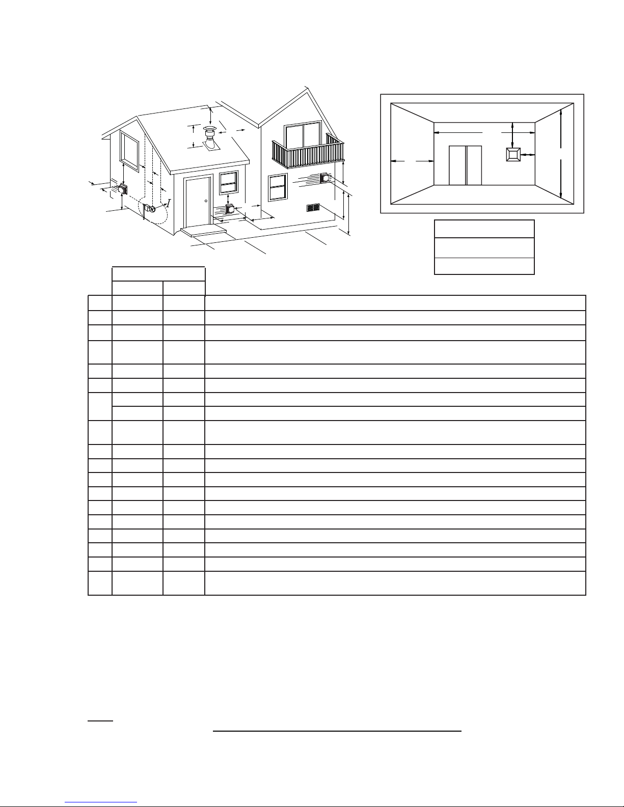
3.3 VENT TERMINAL CLEARANCES
D
E
N
H
C
F
H
A
INSTALLATIONS
CANADA U.S.A.
A 12” 12” Clearance above grade, veranda porch, deck or balcony.
B 12”
C 12” * 12” * Clearance to permanently closed windows.
D 18” ** 18” **
E 12” ** 12” ** Clearance to unventilated soffi t.
F 0” 0” Clearance to an outside corner wall.
G
H 3’ 3’ ****
I 3’ 3’ **** Clearance to a service regulator vent outlet.
J 12” 9” Clearance to a non-mechanical air supply inlet to the building or a combustion air inlet to any other appliance.
K 6’ 3’ † Clearance to a mechanical air supply inlet.
L 7’ ‡ 7’ **** Clearance above a paved sidewalk or paved driveway located on public property.
M 12” †† 12” **** Clearance under a veranda, porch, deck or balcony.
N 16” 16” Clearance above the roof.
O 2’ †* 2’ †* Clearance from an adjacent wall including neighbouring buildings.
P 8’ 8’ Roof must be non-combustible without openings.
Q 3’ 3’ See chart for wider wall dimensions.
R 6’ 6’
Δ
* Recommended to prevent condensation on windows and thermal breakage
** it is recommended to use a heat shield and to maximize the distance to vinyl clad soffi ts.
*** The periscope requires a minimum 18 inches clearance from an inside corner.
**** This is a recommended distance. For additional requirements check local codes.
† 3 feet above if within 10 feet horizontally.
‡ A vent shall not terminate where it may cause hazardous frost or ice accumulations on adjacent property surfaces.
†† Permitted only if the veranda, porch, or deck is fully open on a minimum of two sides beneath the fl oor.
†* Recommended to prevent recirculation of exhaust products. For additional requirements check local codes.
NOTE: Clearances are in accordance with local installation codes and the requirements of the gas supplier.
Δ
0” *** 0” *** Clearance to an inside non-combustible corner wall or protruding non-combustible obstructions (chimney, etc.).
2” *** 2” *** Clearance to an inside combustible corner wall or protruding combustible obstructions (vent chase, etc.).
The terminal shall not be located less than 6 feet under a window that opens on a horizontal plane in a structure with three walls and a roof.
9”
Δ
O
B
O
G
B
Clearance to windows or doors that open.
Vertical clearance to ventilated soffi ts located above the terminal within a horizontal distance of 2’ from
the centerline of the terminal.
Clearance to each side of the centerline extended above the meter / regulator assembly to a maximum
vertical distance of 15’.
See chart for deeper wall dimensions. The terminal shall not be installed on any wall that has an opening between the terminal and the open side of the structure.
COVERED BALCONY APPLICATIONS
Q
M
R
G
P
M
J
K
L
Q
R
R
MIN
MAX
MAX
= 3 feet
= 2 x
feet
12.5B
Q
ACTUAL
W415-0794 / D / 05.30.11
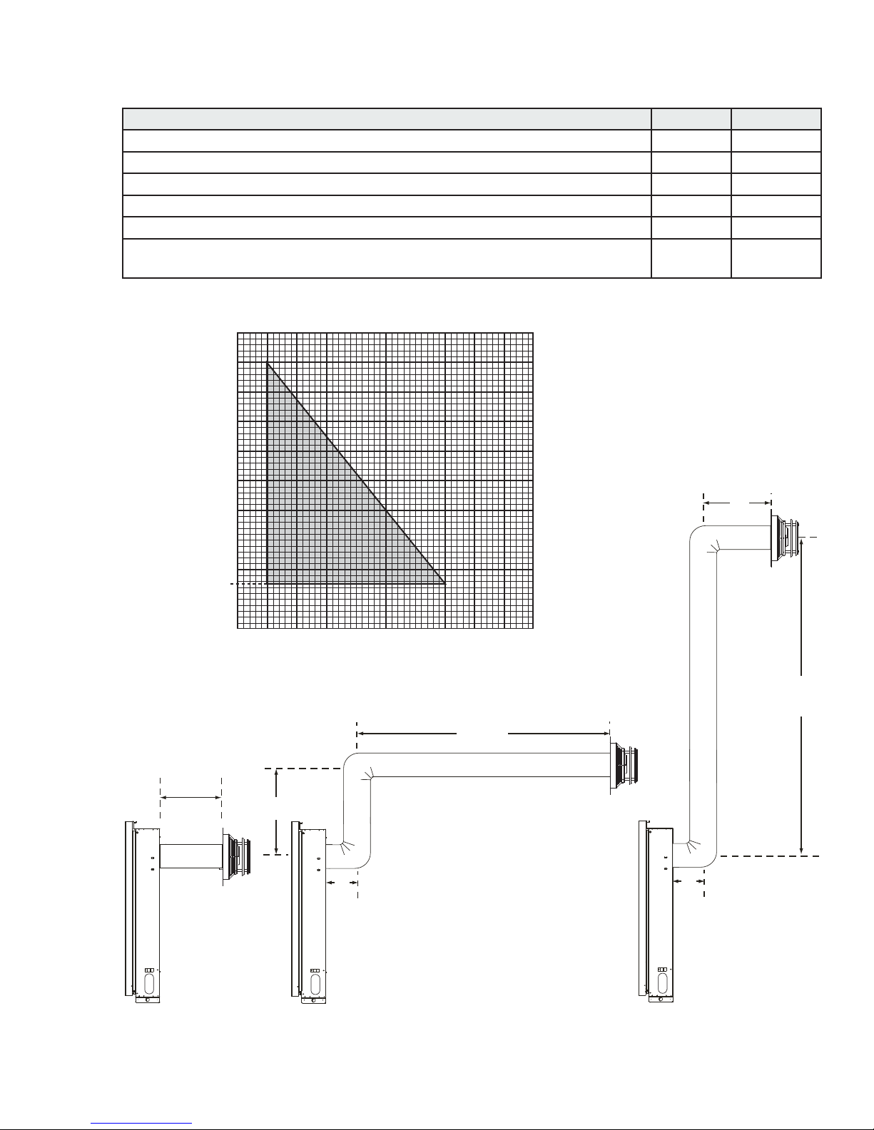
3.4 HORIZONTAL TERMINATION
8”
18” MINIMUM
MAXIMUM
HORIZONTAL
7 FT MAX.
4”
MIN.
Allowable 3” vent connections (excluding appliance and air terminal connections) N/A 1
Rise per foot (recommended) 1/4” N/A
Rise per foot (allowable) 0” N/A
Horizontal run (If vent run does not include vertical rise) 4” 24”
Horizontal run (if vent run includes vertical rise) 4” 7 FT
Vertical run
(* Immediately off the appliance, if 7 FT maximum horizontal run is required)
11
MIN MAX
18”* 7 FT
See graph to determine the required vertical rise VT for the required horizontal rise H
10
9
8
7
6
REQUIRED
VERTICAL
RISE IN
FEET (V
T)
5
4
3
2
1.5
1
0
1 2 3 4 5 6 7 8 9 10
HORIZONTAL VENT RUN PLUS OFFSET IN FEET (HT)
T
.
8”
9 FT
MAX.
4” MIN.
24” MAX.
4”
MIN.
MAXIMUM
VERITICAL
W415-0794 / D / 05.30.11
12
24”
MIN.
MINIMUM
VERITICAL
MAXIMUM
HORIZONTAL
5 FT MAX.
15 FT
MAX.
4”
MIN.
MAXIMUM
VERTICAL
19 1/2 FT
MAX.
4”
MIN.
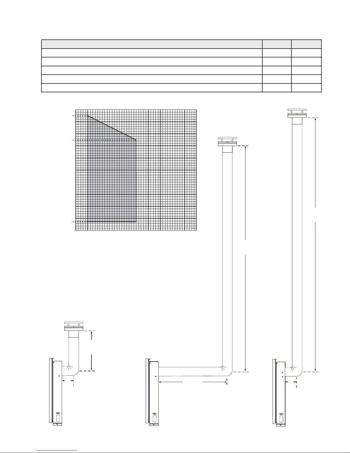
3.5 VERTICAL TERMINATION
Allowable 3” vent connections (excluding appliance and air terminal connections) N/A 2
Rise per foot (recommended) 1/4” N/A
Rise per foot (allowable) 0” N/A
Vertical run (when not venting horizontally) 24” 19 1/2 FT
Horizontal run 4” 5 FT
See graph to determine the required vertical rise VT for the required horizontal rise H
20
19.5
18
16
15
14
MIN MAX
T
.
REQUIRED
VERTICAL
RISE IN
FEET (V
12
10
T)
8
6
4
2
1.33
0
1 2 3 4 5 6 7 8 9 10
HORIZONTAL VENT RUN PLUS OFFSET IN FEET (HT)
24”
MIN.
MINIMUM
4”
VERITICAL
MIN.
W415-0794 / D / 05.30.11
 Loading...