

Napoleon GSS42CFN, GSS42CFP Installation And Operating Instructions Manual
INSTALLER: LEAVE THIS MANUAL WITH THE APPLIANCE.
CONSUMER: RETAIN THIS MANUAL FOR FUTURE REFERENCE.
NEVER LEAVE CHILDREN OR OTHER AT RISK INDIVIDUALS ALONE WITH THE APPLIANCE.
INSTALLATION AND
OPERATING INSTRUCTIONS
SAFETY INFORMATION
!
WARNING
If the information in these instructions are
not followed exactly, a fi re or explosion
may result causing property damage,
personal injury or loss of life.
- Do not store or use gasoline or other fl ammable
vapors and liquids in the vicinity of this or any
other appliance.
- WHAT TO DO IF YOU SMELL GAS:
• Do not try to light any appliance.
• Do not touch any electrical switch; do not use
any phone in your building.
• Immediately call your gas supplier from a
neighbour’s phone. Follow the gas supplier’s
instructions.
• If you cannot reach your gas supplier, call the
fi re department.
- Installation and service must be performed by a
qualifi ed installer, service agency or the supplier.
CERTIFIED FOR CANADA AND UNITED STATES USING ANSI/CSA METHODS.
HOT GLASS WILL CAUSE
BURNS.
DO NOT TOUCH GLASS UNTIL
COOLED.
NEVER ALLOW CHILDREN TO
TOUCH GLASS.
!
DANGER
A barrier designed to reduce the risk of burns from
This appliance is only for use with the type of gas
indicated on the rating plate. This appliance is
not convertible for use with other gases, unless a
certifi ed kit is used.
CERTIFIED UNDER CANADIAN AND AMERICAN NATIONAL STANDARDS, Z21.97 - CSA 2.41.
INSTALLER: LEAVE THIS MANUAL WITH THE APPLIANCE.
CONSUMER: RETAIN THIS MANUAL FOR FUTURE REFERENCE.
NEVER LEAVE CHILDREN OR OTHER AT RISK INDIVIDUALS ALONE WITH THE APPLIANCE.
INSTALLATION AND
OPERATING INSTRUCTIONS
EN
FR
PG
25
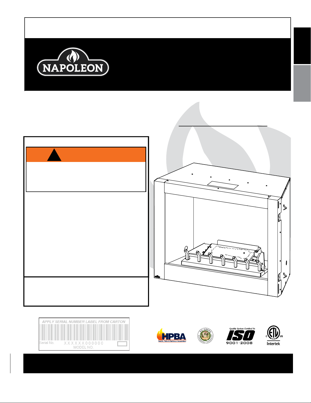
OUTDOOR GAS FIREPLACE
GSS42CFN
NATURAL GAS MODEL
GSS42CFP
PROPANE GAS MODEL
Decorative Product: Not for use as heating appliance.
$10.00
Wolf Steel Ltd., 24 Napoleon Rd., Barrie, ON, L4M 0G8 Canada /
Phone (705)721-1212 • Fax (705)720-9081 • www.napoleonfireplaces.com • hearth@napoleonproducts.com
103 Miller Drive, Crittenden, Kentucky, USA, 41030
WARNING: FOR OUTDOOR USE ONLY
W415-2164 / A / 07.21.16
2
EN
TABLE OF CONTENTS
NOTE: The camera icon indicates video tutorials are available as additional reference, visit
http://mynapoleon.napoleonproducts.com/download/index/44/1
1.0 INSTALLATION OVERVIEW 2
2.0 INTRODUCTION 3
3.0 INSTALLATION 6
4.0 FRAMING 8
5.0 FINISHING 12
6.0 OPTIONAL REMOTE INSTALLATION 14
7.0 OPERATION 15
8.0 ADJUSTMENT 16
9.0 MAINTENANCE 17
10.0 REPLACEMENTS 18
11.0 ACCESSORIES 20
12.0 TROUBLESHOOTING 21
13.0 WARRANTY 23
2.1 DIMENSIONS 4
2.2 GENERAL INSTRUCTIONS 4
2.3 GENERAL INFORMATION 5
2.4 RATING PLATE INFORMATION 5
3.1 GAS INSTALLATION 6
3.2 GAS INLET LOCATIONS 7
3.3 OPTIONAL WALL SWITCH INSTALLATION 7
3.4 COMBUSTION AND VENTILATION AIR 8
4.1 CLEARANCE TO COMBUSTIBLES 8
4.2 MINIMUM ENCLOSURE CLEARANCES 10
4.3 MINIMUM MANTEL CLEARANCES 11
4.4 NAILING TAB 11
5.1 LOG PLACEMENT 12
5.2 GLOWING EMBERS (OPTIONAL) 13
5.3 CHARCOAL LUMPS/LAVA ROCK 13
5.4 LOGO PLACEMENT 14
8.1 VENTURI ADJUSTMENT 16
8.2 FLAME CHARACTERISTICS 16
10.1 OVERVIEW AND VALVE TRAIN ASSEMBLY 19
NOTE: Changes, other than editorial, are denoted by a vertical line in the margin.
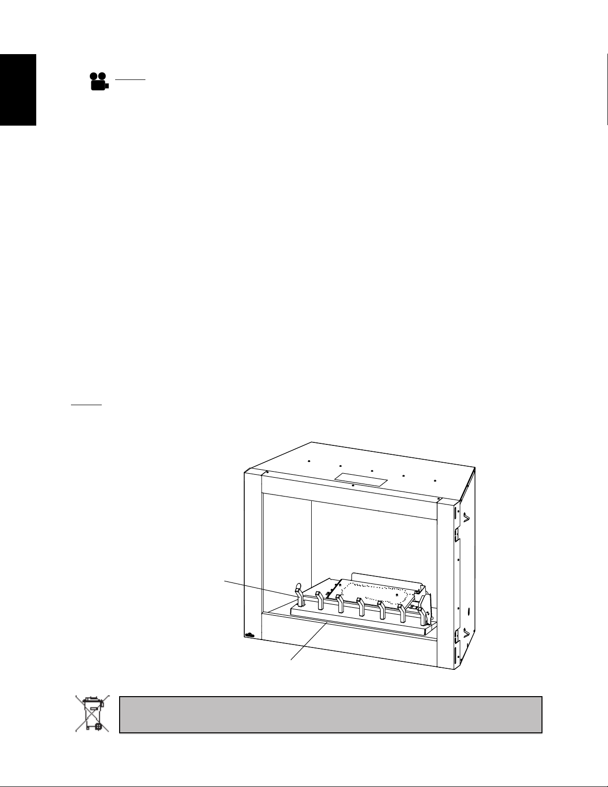
1.0 INSTALLATION OVERVIEW
Refer to “GRATE
ASSEMBLY” section.
Refer to “RATING
PLATE INFORMATION”
section.
Batteries must be disposed of according to the local laws and regulations. Some batteries may be
recycled, and may be accepted for disposal at your local recycling center. Check with your municipality
for recycling instructions.
W415-2164 / A / 07.21.16

!
WARNING
Provide adequate ventilation and combustion air. Provide adequate accessibility clearance for servicing
2.0 INTRODUCTION
• THIS APPLIANCE IS HOT WHEN OPERATED AND CAN CAUSE SEVERE BURNS IF CONTACTED.
• Do not operate appliance before reading and understanding operating instructions. Failure to operate
appliance according to operating instructions could cause fi re or injury.
• Any changes to this appliance or its controls can be dangerous and is prohibited.
• Risk of burns. The appliance should be turned off and cooled before servicing.
• Do not install damaged, incomplete or substitute components.
• Risk of cuts and abrasions. Wear protective gloves and safety glasses during installation. Sheet metal
edges may be sharp.
• Do not burn wood or other materials in this appliance.
•
and operating the appliance. Never obstruct the front opening of the appliance.
• If appliance keeps shutting off, have it serviced. Keep burner and control compartment clean.
• Do not allow wind to blow directly into the appliance. Avoid any drafts that alter burner fl ame patterns.
• Children and adults should be alerted to the hazards of high surface temperature and should stay away
to avoid burns or clothing ignition.
• Young children should be carefully supervised when they are in the same area as the appliance.
Toddlers, young children and others may be susceptible to accidental contact burns. A physical
barrier is recommended if there are at risk individuals in the vicinity of the appliance. To restrict access
to an appliance, install an adjustable safety gate to keep toddlers, young children and other at risk
individuals away from hot surfaces.
• Clothing or other fl ammable material should not be placed on or near the appliance.
• Furniture or other objects must be kept a minimum of 4 feet away from the front of the appliance.
• Ensure you have incorporated adequate safety measures to protect infants/toddlers from touching hot
surfaces.
• Even after the appliance is off, it will remain hot for an extended period of time.
• Check with your local hearth specialty dealer for safety screens and hearth guards to protect children
from hot surfaces. These screens and guards must be fastened to the fl oor.
• Any safety screen or guard removed for servicing must be replaced prior to operating the appliance.
• It is imperative that the control compartments, burners and circulating blower and its passageway in
the appliance and venting system are kept clean. The appliance should be inspected before use and
at least annually by a qualifi ed service person. The appliance area must be kept clear and free from
combustible materials, gasoline and other fl ammable vapors and liquids.
• Under no circumstances should this appliance be modifi ed.
• Do not use this appliance if any part has been under water. Immediately call a qualifi ed service
technician to inspect the appliance and to replace any part of the control system and any gas control
which has been under water.
• Keep the packaging material out of reach of children and dispose of the material in a safe manner. As
with all plastic bags, these are not toys and should be kept away from children and infants.
• This appliance must not be installed indoors or within any structure that prevents or inhibits the
exhaust gases from dissipating in the outside atmosphere.
3.14C
3
EN
W415-2164 / A / 07.21.16
4
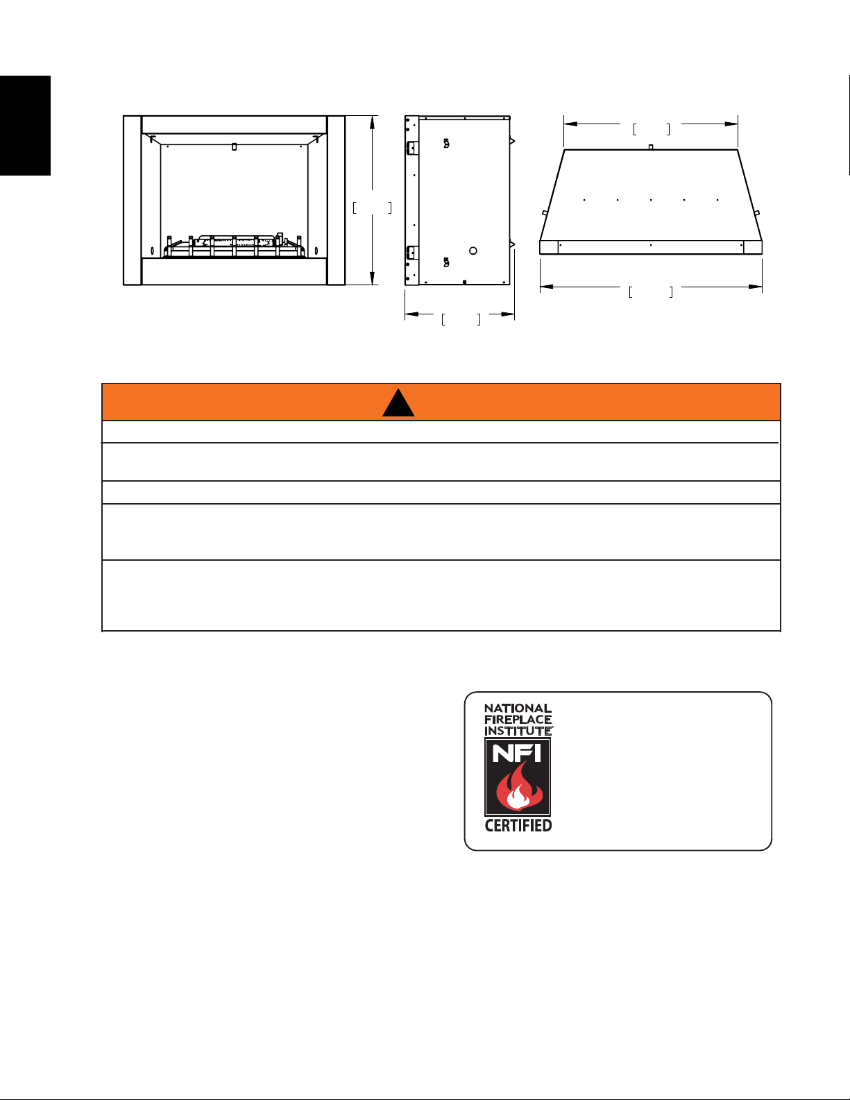
FRONT VIEW RIGHT SIDE VIEW TOP VIEW
WARNING
ALWAYS LIGHT THE PILOT WHETHER FOR THE FIRST TIME OR IF THE GAS SUPPLY HAS RAN OUT,
WITH THE GLASS DOOR OPENED OR REMOVED.
ING GAS LINE AT TEST PRESSURES ABOVE 1/2 PSIG. CLOSE THE MANUAL SHUT-OFF VALVE BEFORE
!
WARNING
2.1 DIMENSIONS
EN
35 5/8"
905mm
36 5/16"
922mm
46 11/16"
1186mm
23"
585mm
2.2 GENERAL INSTRUCTIONS
!
NEVER OBSTRUCT THE FRONT OPENING OF THE APPLIANCE.
OBJECTS PLACED IN FRONT OF THE APPLIANCE MUST BE KEPT A MINIMUM OF 48” (1219.2mm)
FROM THE FRONT FACE OF THE APPLIANCE.
FIRE RISK. EXPLOSION HAZARD.
HIGH PRESSURE WILL DAMAGE VALVE. DISCONNECT GAS SUPPLY PIPING BEFORE PRESSURE TEST-
PRESSURE TESTING GAS LINE AT TEST PRESSURES EQUAL TO OR LESS THAN 1/2 PSIG (35mb).
USE ONLY WOLF STEEL APPROVED OPTIONAL ACCESSORIES AND REPLACEMENT PARTS WITH
THIS APPLIANCE. USING NON-LISTED ACCESSORIES (BLOWERS, DOORS, LOUVRES, TRIMS, GAS
COMPONENTS, VENTING COMPONENTS, ETC.) COULD RESULT IN A SAFETY HAZARD AND WILL
VOID THE WARRANTY AND CERTIFICATION.
THIS GAS APPLIANCE SHOULD BE INSTALLED AND SERVICED BY A QUALIFIED INSTALLER to
conform with local codes. Installation practices vary from region to region and it is important to know
the specifics that apply to your area, for example in
Massachusetts State:
• The appliance off valve must be a “T” handle gas
cock.
• The flexible connector must not be longer than 36”
(914.4mm).
The installation must conform with local codes or, in
absence of local codes, the National Gas and Propane
Installation Code CSA B149.1 in Canada, or the National
Fuel Gas Code, ANSI Z223.1 / NFPA 54 in the United States.
The appliance and its individual shutoff valve must be disconnected from the gas supply piping system during
any pressure testing of that system at test pressures in excess of 1/2 psig (3.5 kPa). The appliance must be
isolated from the gas supply piping system by closing its individual manual shutoff valve during any pressure
testing of the gas supply piping system at test pressures equal to or less than 1/2 psig (3.5 kPa).
When the appliance is installed directly on combustible material other than wood flooring, the appliance shall
be installed on a metal or wood panel extending the full width and depth.
www.ncertied.org
We suggest that our gas
hearth products be installed
and serviced by professionals
who are certied in the U.S.
by the National Fireplace
®
Institute
(NFI) as NFI Gas
Specialists
W415-2164 / A / 07.21.16
SI L’APPAREIL EST ÉQUIPÉ D’UN RÉGULATEUR DE PRESSION D’ALIMENTATION, IL DOIT ÊTRE
UTILISÉ. LORSQUE CET APPAREIL N’EST PAS UTILISÉ, VOUS DEVEZ FERMER L’ALIMENTATION EN
AUTRE APPAREIL. UNE INSTALLATION NON CONFORME, DES AJUSTEMENTS, DES
ALTÉRATIONS, UN SERVICE OU UN ENTRETIEN INADÉQUATS PEUVENT CAUSER DES
DOMMAGES À LA PROPRIÉTÉ OU DES BLESSURES CORPORELLES. RÉFÉREZ-VOUS AU
MANUEL D’INSTRUCTIONS FOURNI AVEC CET APPAREIL. POUR DE L’ASSISTANCE OU POUR
OU LE FOURNISSEUR DE GAZ. NE PAS UTILISER POUR LA CUISSON. POUR USAGE
EXTÉTIEUR SEULEMENT. SI ENTREPOSÉ À L’INTÉRIEUR, DÉTACHER LA BONBONNE DE
PROPANE ET LA LAISSER À L’EXTÉRIEUR.
2.3 GENERAL INFORMATION
SAMPLE
FOR YOUR SATISFACTION, THIS APPLIANCE HAS BEEN TEST-FIRED TO ASSURE ITS OPERATION
Altitude (FT) 0-2,000 * 0-2,000
Max. Input (BTU/HR) 65,000 65,000
Min. Inlet Gas Supply Pressure 4.5" (11mb) w.c. 11" (27mb) w.c.
Max. Inlet Gas Supply Pressure 13" (32mb) w.c. 13" (32mb) w.c.
Manifold Pressure (Under Flow Conditions) 3.5" (9mb) w.c. 10" (25mb) w.c.
* When the appliance is installed at elevations above 2,000ft, and in the absence of specific recommendations
from the local authority having jurisdiction, the certified high altitude input rating shall be reduced at the rate
of 4% for each additional 1,000ft.
It is highly recommended to protect the logs from moisture (rain, snow). Cover the enclosure opening when
not in use.
This appliance is only for use with the type of gas indicated on the rating plate. This appliance is not
convertible for use with other gases, unless a certified kit is used.
No external electricity (110 volts or 24 volts) is required for the millivolt operating system.
Expansion / contraction noises during heating up and cooling down cycles are normal and are to be
expected.
AND QUALITY!
RATES AND EFFICIENCIES
5
EN
NG LP
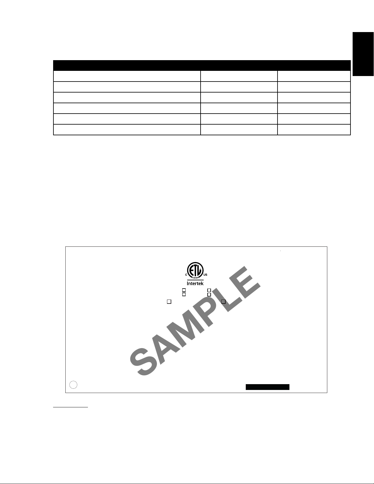
2.4 RATING PLATE INFORMATION
IF APPLIANCE HAS BEEN SUPPLIED WITH A GAS PRESSURE REGULATOR, IT MUST BE USED. THE
GAS SUPPLY MUST BE TURNED OFF AT THE LP-GAS SUPPLY CYLINDER WHEN THIS APPLIANCE IS
NOT IN USE. DO NOT STORE OR USE GASOLINE OR OTHER FLAMMABLE VAPOURS AND
LIQUIDS IN THE VICINITY OF THIS OR ANY OTHER APPLIANCE.
IMPROPER INSTALLATION, ADJUSTMENT, ALTERATION, SERVICE OR MAINTENANCE CAN
CAUSE INJURY OR PROPERTY DAMAGE. REFER TO THE OWNER’S MANUAL PROVIDED
WITH THIS APPLIANCE. FOR ASSISTANCE OR ADDITIONAL INFORMATION, CONSULT A
QUALIFIED INSTALLER, SERVICE AGENCY OR GAS SUPPLIER. MUST NOT BE USED FOR
COOKING. FOR OUTDOOR USE ONLY. IF STORED INDOORS, DETACH AND LEAVE CYLINDER
OUTDOORS.
NOT FOR USE WITH SOLID FUEL.
WARNING: THIS FIREPLACE USES AND REQUIRES A FAST ACTING THERMOCOUPLE.
REPLACE ONLY WITH A FAST ACTING THERMOCOUPLE SUPPLIED BY WOLF STEEL LTD.
DO NOT ADD ANY MATERIAL TO THE APPLIANCE, WHICH WILL COME IN CONTACT WITH THE
FLAMES, OTHER THAN THAT SUPPLIED BY THE MANUFACTURER WITH THE APPLIANCE.
MINIMUM CLEARANCE TO COMBUSTIBLE MATERIALS:
TOP 18” BACK 1”
FLOOR 0“ MANTEL NON-COMBUSTIBLE
SIDES 1”
SEE INSTALLATION INSTRUCTIONS FOR FRAMING CLEARANCES.
INSTALLER: It is your responsibility to check off the appropriate box on the rating plate according to
the model, venting and gas type of the appliance.
For rating plate location, see “INSTALLATION OVERVIEW” section.
This illustration is for reference only. Refer to the rating plate on the appliance for accurate information.
NOTE: The rating plate must remain with the appliance at all times. It must not be removed.
CERTIFIED UNDER / HOMOLOGUÉ SELON LES NORMES: ANSI Z21.97 - CSA 2.41. OUTDOOR GAS FIREPLACE / FOYER AU GAZ EXTÉRIEUR
9700539 (WSL) 4001657 (NGZ)
4001658 (NAC) 4001659 (WUSA)
GSS42CFN MODEL GSS42CFP
65,000 BTU/h INPUT / ALIMENTATION 65,000 BTU/h
40,000 BTU/h REDUCED INPUT / ALIMENTATION RÉDUITE 50,000 BTU/h
PRESSION AU COLLECTEUR: 3.5" D'UNE COLONNE D'EAU PRESSION AU COLLECTEUR: 10" D'UNE COLONNE D'EAU
PRESSION D'ALIMENTATION MINIMALE: 4.5" D'UNE COLONNE D'EAU PRESSION D'ALIMENTATION MINIMALE: 11" D'UNE COLONNE D'EAU
PRESSION D'ALIMENTATION MAXIMALE: 7.0" D'UNE COLONNE D'EAU PRESSION D'ALIMENTATION MAXIMALE: 13" D'UNE COLONNE D'EAU
WOLF STEEL LTD.
24 NAPOLEON ROAD, BARRIE, ON, L4M 0G8 CANADA
0-4500FT (0-1370m) ALTITUDE / ÉLÉVATION 0-4500FT (0-1370m)
MANIFOLD PRESSURE: 3.5" WATER COLUMN MANIFOLD PRESSURE: 10" WATER COLUMN
MINIMUM SUPPLY PRESSURE: 4.5" WATER COLUMN MINIMUM SUPPLY PRESSURE: 11" WATER COLUMN
MAXIMUM SUPPLY PRESSURE: 7.0" WATER COLUMN MAXIMUM SUPPLY PRESSURE: 13" WATER COLUMN
GAZ SUR LA BONBONNE DE PROPANE. N’ENTREPOSEZ PAS ET N’UTILISEZ PAS D’ESSENCE
OU AUTRES LIQUIDES ET VAPEURS INFLAMMABLES À PROXIMITÉ DE CET APPAREIL OU TOUT
PLUS D’INFORMATION, CONSULTEZ UN INSTALLATEUR QUALIFIÉ, UNE AGENCE D’ENTRETIEN
UN COMBUSTIBLE SOLIDE NE DOIT PAS ÊTRE UTILISÉ
AVEC CET APPAREIL
AVERTISSEMENT: CE FOYER UTILISE ET REQUIERT UN THERMOCOUPLE À ACTION
RAPIDE. REPLACEZ UNIQUEMENT AVEC UN THERMOCOUPLE À ACTION RAPIDE DE WOLF STEEL
LTÉE. N'AJOUTEZ PAS A CET APPAREIL AUCUN MATÉRIAUX DEVANT ENTRER EN CONTACT AVEC
LES FLAMMES AUTRE QUE CELUI QUI EST FOURNI AVEC CET APPAREIL PAR LE FABRICANT.
DÉGAGEMENTS MINIMAUX DES MATÉRIAUX COMBUSTIBLES:
DESSUS 18” ARRIÈRE 1”
PLANCHER 0“ MANTEAU INCOMBUSTIBLE
CÔTÉS 1”
POUR LES DÉGAGEMENTS AUX MATÉRIAUX D’OSSATURE, VOIR LE MANUEL D’INSTRUCTIONS.
SERIAL NUMBER/NO. DE SÉRIE:
GSS42
W385-2161 / A
W415-2164 / A / 07.21.16
6
WARNING
RISK OF FIRE, EXPLOSION OR ASPHYXIATION. ENSURE THERE ARE NO IGNITION SOURCES SUCH AS
SUPPORT GAS CONTROL WHEN ATTACHING GAS SUPPLY PIPE TO PREVENT DAMAGING GAS LINE.
!
WARNING
RISK OF FIRE, EXPLOSION OR ASPHYXIATION. ENSURE THERE ARE NO IGNITION SOURCES SUCH AS
SPARKS OR OPEN FLAMES.
SUPPORT GAS CONTROL WHEN ATTACHING GAS SUPPLY PIPE TO PREVENT DAMAGING GAS LINE.
ALWAYS LIGHT THE PILOT WHETHER FOR THE FIRST TIME OR IF THE GAS SUPPLY HAS RUN OUT
WITH THE GLASS DOOR OPENED OR REMOVED. PURGING OF THE GAS SUPPLY LINE SHOULD BE
PERFORMED BY A QUALIFIED SERVICE TECHNICIAN. ASSURE THAT A CONTINUOUS GAS FLOW IS AT
THE BURNER BEFORE CLOSING THE DOOR. ENSURE ADEQUATE VENTILATION. FOR GAS AND
ELECTRICAL LOCATIONS, SEE “DIMENSIONS” SECTION.
3.0 INSTALLATION
3.1 GAS INSTALLATION
EN
PURGING OF THE GAS SUPPLY LINE SHOULD BE PERFORMED BY A QUALIFIED SERVICE
TECHNICIAN. ASSURE THAT A CONTINUOUS GAS FLOW IS AT THE BURNER BEFORE CLOSING
THE DOOR. ENSURE ADEQUATE VENTILATION. FOR GAS AND ELECTRICAL LOCATIONS, SEE
ALL GAS CONNECTIONS MUST BE CONTAINED WITHIN THE APPLIANCE WHEN COMPLETE.
HIGH PRESSURE WILL DAMAGE VALVE. DISCONNECT GAS SUPPLY PIPING BEFORE TESTING GAS
Installation and servicing to be done by a qualified installer.
• Move the appliance into position and secure.
• If equipped with a flex connector the appliance is designed to accept a 1/2” (13mm) gas supply.
Without the connector it is designed to accept a 3/8” (9.5mm) gas supply. The appliance is equipped
with a manual shut off valve to turn off the gas supply to the appliance.
• Connect the gas supply in accordance to local codes. In the absence of local codes, install to the
current CAN/CSA-B149.1 Installation Code in Canada or to the current National Fuel Gas Code, ANSI
Z223.1 / NFPA 54 in the United States.
• When flexing any gas line, support the gas valve so that the lines are not bent or kinked.
• The gas line flex-connector should be installed to provide sufficient movement for shifting the burner
assembly on its side to aid with servicing components.
• Check for gas leaks by brushing on a soap and water solution. Do not use open flame.
!
SPARKS OR OPEN FLAMES.
“DIMENSION” SECTION.
LINE AT TEST PRESSURES ABOVE 1/2 PSIG.
VALVE SETTINGS HAVE BEEN FACTORY SET, DO NOT CHANGE.
W415-2164 / A / 07.21.16
For ease of accessibility, an optional remote wall switch or millivolt thermostat may be installed in a convenient
location. Route a 2 strand, solid core millivolt wire from the valve to the wall switch or millivolt thermostat. The
recommended maximum lead length depends on wire size:
14 gauge 100 feet
16 gauge 60 feet
18 gauge 40 feet
Disconnect the existing wires from terminals 1 and 3 (from the
ON/OFF switch) and replace with the leads from the wall switch / millivolt thermostat.
50.3
WARNING
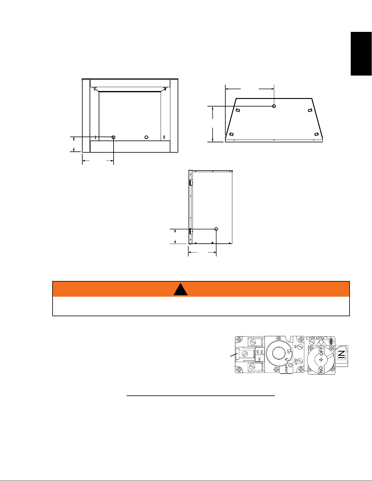
3.2 GAS INLET LOCATIONS
7 1/
8
"
"14
"23
5
/
16
16 1/
16
"
"15
/
"23 5/
16
16 1/
16
"
7
There are five gas inlet locations on the ventless firebox enclosure. One on each side of the appliance, two
at the rear, and one on the bottom. Using the following illustrations identify the preferred inlet and remove
corresponding knock out.
"23 5/
16
"
16 1/
16
"
7 1/
8
5
16
EN
"
7 1/
8
"14
3.3 OPTIONAL WALL SWITCH INSTALLATION
!
DO NOT CONNECT EITHER THE WALL SWITCH, THERMOSTAT OR GAS VALVE DIRECTLY TO 110
VOLT ELECTRICITY.
WIRE SIZE MAX. LENGTH
TP
W415-2164 / A / 07.21.16
P
I
L
O
T
8
WARNING
3.4 COMBUSTION AND VENTILATION AIR
EN
This appliance is intended for installation on an outdoor patio or in your yard. It must never be installed inside
the warm air envelope of your structure.
It is highly recommended that this appliance be installed in a “sheltered” area. Direct wind will cause an
erratic flame and possible pilot or main burner outage.
An erratic flame could also lead to excessive carboning (black soot) which is not a safety issue but is visually
undesirable.
Typical installation may include covered patio, screened porch, gazebo or on an outside wall of a house.
* If installing a propane appliance, the propane cylinder must always be on the exterior of such a
structure.
NOTE: Ensure the area has adequate ventilation.
4.0 FRAMING
4.1 CLEARANCE TO COMBUSTIBLES
IN ORDER TO AVOID THE POSSIBILITY OF EXPOSED INSULATION OR VAPOUR BARRIER COMING
IN CONTACT WITH THE APPLIANCE BODY, IT IS RECOMMENDED THAT THE WALLS OF THE
APPLIANCE ENCLOSURE BE “FINISHED” (IE: DRYWALL / SHEETROCK), AS YOU WOULD FINISH
ANY OTHER OUTSIDE WALL OF A HOME. THIS WILL ENSURE THAT CLEARANCE TO
COMBUSTIBLES IS MAINTAINED WITHIN THE CAVITY.
DO NOT NOTCH THE FRAMING AROUND THE APPLIANCE STAND-OFFS. FAILURE TO MAINTAIN
AIR SPACE CLEARANCE MAY CAUSE OVER HEATING AND FIRE. PREVENT CONTACT WITH
SAGGING OR LOOSE INSULATION OR FRAMING AND OTHER COMBUSTIBLE MATERIALS. BLOCK
OPENING INTO THE CHASE TO PREVENT ENTRY OF BLOWN-IN INSULATION. MAKE SURE
WHEN CONSTRUCTING THE ENCLOSURE ALLOW FOR FINISHING MATERIAL THICKNESS TO
MAINTAIN CLEARANCES. FRAMING OR FINISHING MATERIAL CLOSER THAN THE MINIMUMS
LISTED MUST BE CONSTRUCTED ENTIRELY OF NON-COMBUSTIBLE MATERIALS. MATERIALS
CONSISTING ENTIRELY OF STEEL, IRON, BRICK, TILE, CONCRETE, SLATE, GLASS OR PLASTERS,
OR ANY COMBINATION THEREOF ARE SUITABLE. MATERIALS THAT ARE REPORTED AS PASSING
ASTM E 136, STANDARD TEST METHOD FOR BEHAVIOUR OF MATERIALS IN A VERTICAL TUBE
FURNACE AT 1382° F (750°C) AND UL763 SHALL BE CONSIDERED NON-COMBUSTIBLE
MINIMUM CLEARANCE TO COMBUSTIBLES MUST BE MAINTAINED OR A SERIOUS FIRE HAZARD
THE APPLIANCE REQUIRES A MINIMUM ENCLOSURE HEIGHT. MEASURE FROM THE APPLIANCE
IF STEEL STUD FRAMING KITS WITH CEMENT BOARD ARE PROVIDED, OR SPECIFIED IN THE
IF SPECIFIED IN THE INSTALLATION INSTRUCTION FINISHING MUST BE DONE USING A NON-
COMBUSTIBLE MATERIAL SUCH AS NON-COMBUSTIBLE BOARD, CERAMIC TILE, MARBLE, ETC.
DO NOT USE WOOD OR DRYWALL. ANY FIRE RATED DRYWALL IS NOT ACCEPTABLE
INSULATION AND OTHER MATERIALS ARE SECURED.
INSTALLATION INSTRUCTIONS, THEY MUST BE INSTALLED.
!
RISK OF FIRE!
MATERIALS.
COULD RESULT.
BASE.
71.1C
W415-2164 / A / 07.21.16
9
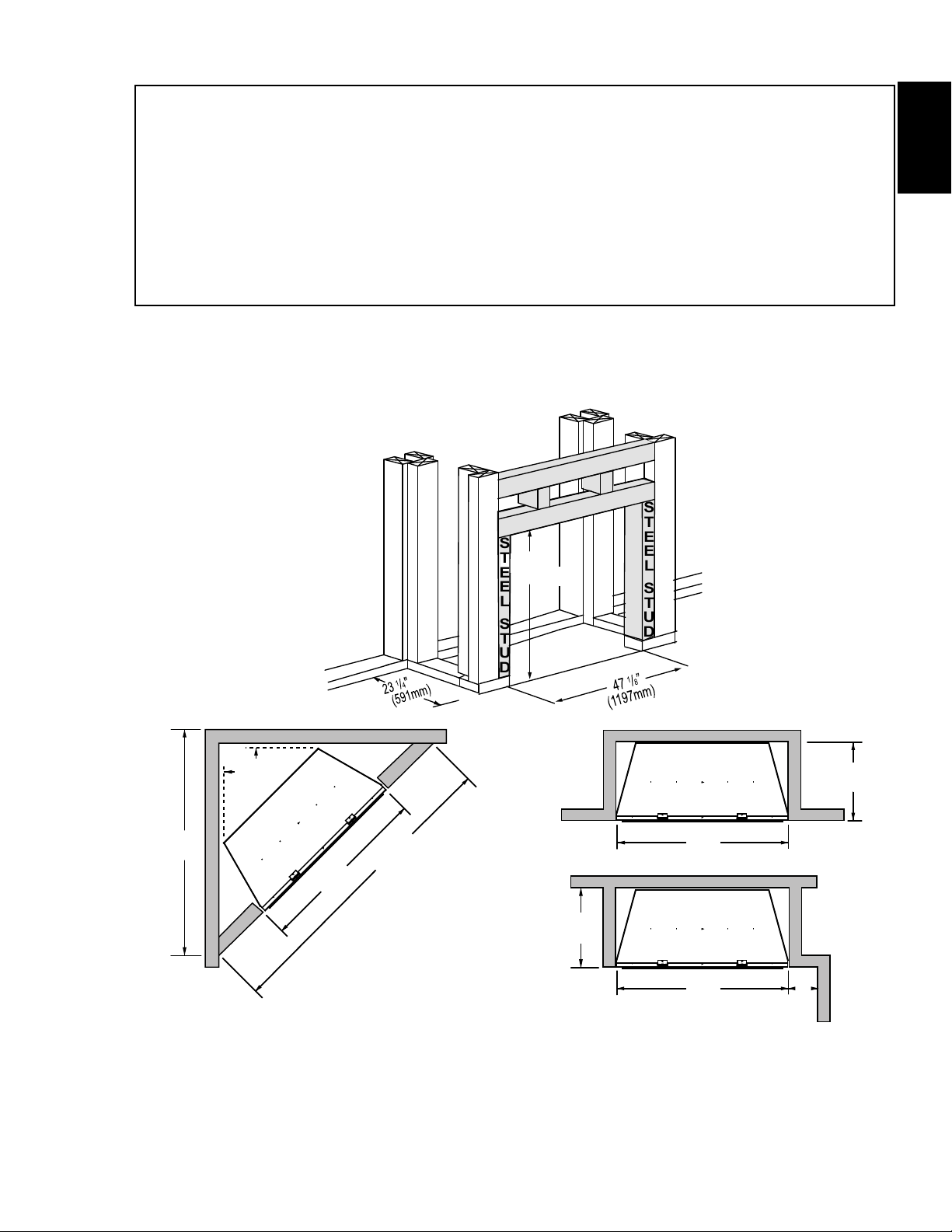
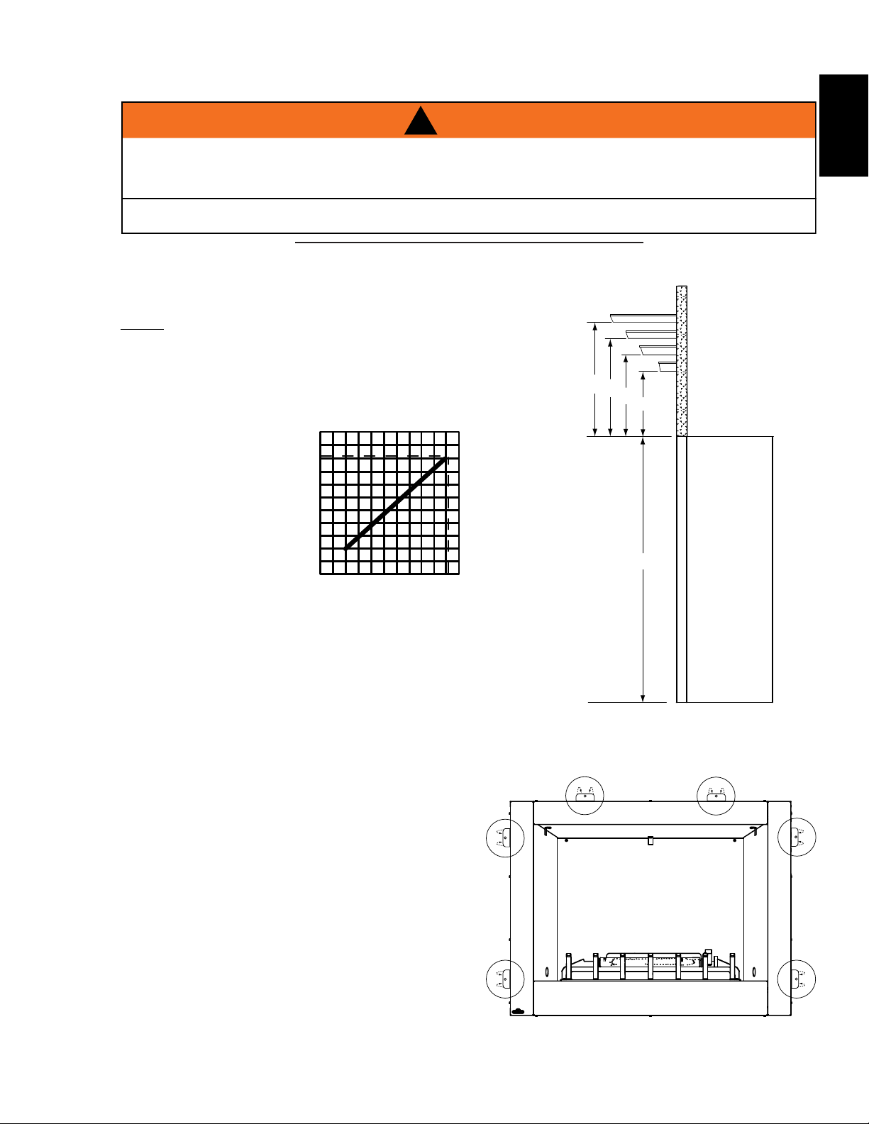
Minimum Clearance to Combustibles construction from appliance and vent surfaces:
Framing 0” (0mm) to stand-offs (rear and sides only)
Use a steel header for the top and two steel studs on the sides.
Finishing 1” (25mm) to back and sides
Non-combustible finishing 18” (457mm)to top
4”(102mm) to sides of appliance opening
Non-combustible finishing material (ie. cement board, brick, stone, tile)
may be used to finish the front of the appliance.
Recessed depth 23 1/4” (587mm)
Enclosure top 58 1/2” (1486mm) from bottom of appliance
Clearance to ceiling 84” (2134mm) from bottom of appliance.
It is recommended that the walls of the appliance enclosure be finished. This would ensure that clearance to
combustibles is maintained within the cavity.
It is best to frame your appliance after it is positioned. Use 2x4’s and frame to local building codes.
EN
"70 1/
8
(1781mm)
"1
(25mm)
"47 1/
8
(1197mm)
"
99 3/16
(2519mm)
STEEL HEADER
STEEL HEADER
STEEL
36"
(914mm)
STUD
OUTSIDE
CHASE
1
23
/
4
"
(591mm)
STEEL
STUD
"47 1/
8
(1197mm)
(591mm)
INSIDE
CHASE
23 1/
"
4
"47 1/
8
(1197mm)
"18
(457mm)
W415-2164 / A / 07.21.16

10
55 1/8"
4"
4"
47
1
/8"
53 3/4"
18" *
OUTDOOR
SEALANT **
NON-COMBUSTIBLE
FINISHING MATERIAL
STEEL
HEADER
STEEL
STUD
STEEL
STUD
EN
4.2 MINIMUM ENCLOSURE CLEARANCES
USE ONLY NON-COMBUSTIBLE MATERIAL SUCH AS CEMENT BOARD, CERAMIC TILE, MARBLE,
ETC. WHEN FINISHING TO THE APPLIANCE. DO NOT USE WOOD OR DRYWALL.
*From top of unit.
** An outdoor sealant must be used along the
edge of the fireplace and the non-combustible
material to keep water from entering the chase.
!
WARNING
W415-2164 / A / 07.21.16
This appliance requires a minimum enclosure height of 58 1/2”.
For temperature requirements, the enclosure space around and above the fireplace must be left unobstructed.
WARNING
4.3 MINIMUM MANTEL CLEARANCES
11
!
RISK OF FIRE, MAINTAIN ALL SPECIFIED AIR SPACE CLEARANCES TO COMBUSTIBLES. FAILURE
TO COMPLY WITH THESE INSTRUCTIONS MAY CAUSE A FIRE OR CAUSE THE APPLIANCE TO
OVERHEAT. ENSURE ALL CLEARANCES (I.E. BACK, SIDE, TOP, VENT, MANTEL, FRONT, ETC.) ARE
CLEARLY MAINTAINED.
WHEN USING PAINT OR LACQUER TO FINISH THE MANTEL, THE PAINT OR LACQUER MUST BE
HEAT RESISTANT TO PREVENT DISCOLOURATION.
73.1
We recommend all mantels made from non-combustible material. If using combustible materials, follow the
chart below.
8” MANTEL
NOTE: Mantel temperatures will rise above normal
temperatures and may be hot to the touch.
32
30
MANTEL
HEIGHT
28
26
TOP OF
FIREPLACE
30”
28”
6”
26”
4”
2”
24”
EN
4.4 NAILING TAB
To install the appliance face flush with the finished
surface, position the framework to accommodate
the thickness of the finished surface. Bend out the
six nailing tabs, attached on top and on either side
of the appliance and secure to the 2x4 framing. The
tabs will facilitate the installation of either a
finished surface thickness.
24
42
86 10
MANTEL
DEPTH
1
/
” or 3/4”
2
35 3/4”
W415-2164 / A / 07.21.16
12
WARNING
5
PINS
5
PINS
PORT CAVITY
5
PINS
PORT CAVITY
5
PINS
PINS
PORT CAVITY
5.0 FINISHING
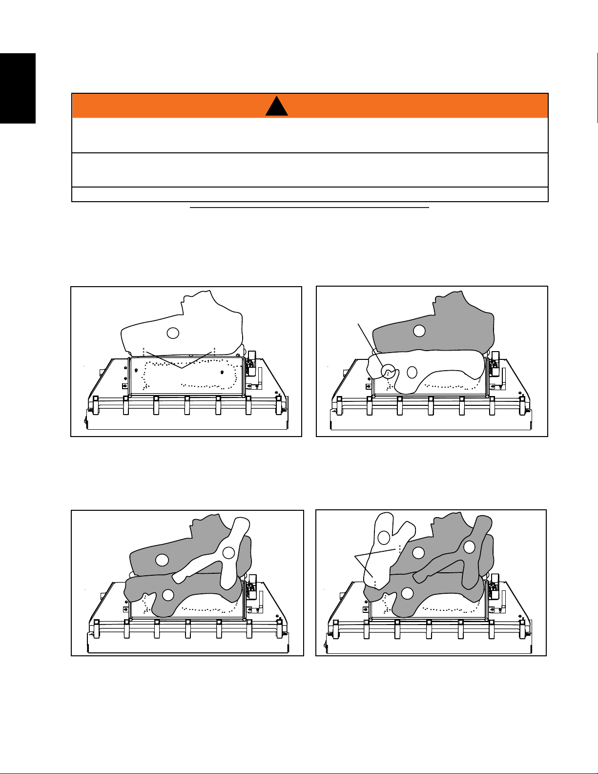
5.1 LOG PLACEMENT
EN
FAILURE TO POSITION THE LOGS IN ACCORDANCE WITH THESE DIAGRAMS OR FAILURE TO USE
ONLY LOGS SPECIFICALLY APPROVED WITH THIS APPLIANCE MAY RESULT IN PROPERTY
LOGS MUST BE PLACED IN THEIR EXACT LOCATION IN THE APPLIANCE. DO NOT MODIFY THE
PROPER LOG POSITIONS, SINCE APPLIANCE MAY NOT FUNCTION PROPERLY AND DELAYED
PHAZERTM logs and glowing embers exclusive to Napoleon, provide a unique and realistic glowing effect that
is different in every installation. Take the time to carefully position the glowing embers for a maximum glowing
effect.
Log colours may vary. During the initial use of the appliance, the colours will become more uniform as colour
pigments burn in during the heat activated curing process.
!
DAMAGE OR PERSONAL INJURY.
IGNITION MAY OCCUR.
THE LOGS ARE FRAGILE AND SHOULD BE HANDLED WITH CARE.
76.1A
A
A. Place the rear log (W135-0668) onto the
locating pins along the back edge of the
burner.
C
A
B
A
B
B. Position the middle log (W135-0669) onto
the locator pins on the burner. Ensure the
port cavity on the underside of the log is
positioned such that it runs over the ports
allowing them to be exposed.
D
A
C
B
W415-2164 / A / 07.21.16
C. Place the end of the crossover log
(W135-0672) on the right side of the knot of
log A. The “Y” in the log should straddle the
knot on top of log B.
D. Place one pin into the left side of log A and
one into the left side of log B. Place the left
side log (W135-0671) onto the pins located in
the left side of logs A and B.
13
5
5
5
D
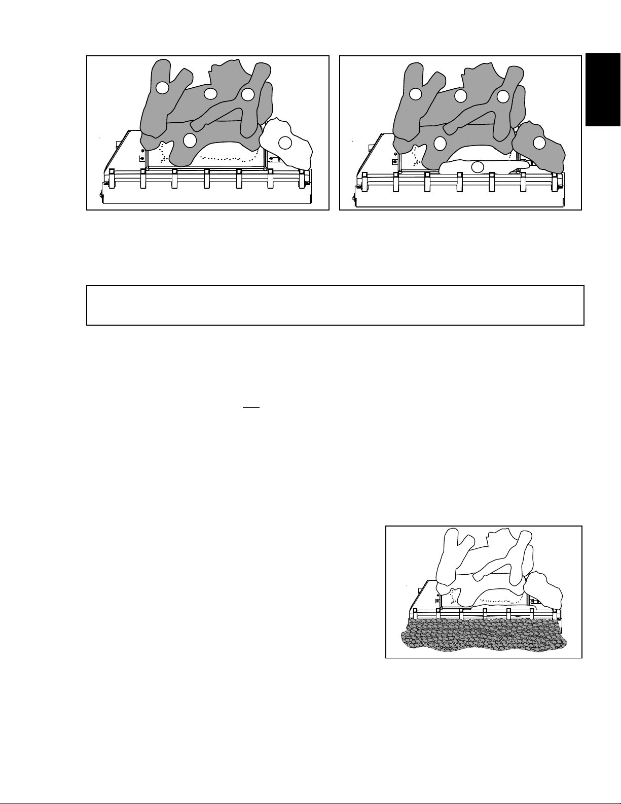
E. Position the slot in the bottom of the right
log (W135-0670) onto the bracket beside the
burner on the right, with the charred face of
the log to the front.
A
B
IT IS HIGHLY RECOMMENDED TO PROTECT THE LOGS FROM MOISTURE.
C
COVER THE FIREBOX WHEN NOT IN USE.
5.2 GLOWING EMBERS (OPTIONAL)
Glowing embers (not supplied) may be used to enhance the flame’s appearance. Tear the embers into pieces
and place along the front row of ports covering all of the burner area in front of the small logs. Care should
be taken to shred the embers into thin, small irregular pieces as only the exposed edges of the fibre hairs will
glow. The ember material will only glow when exposed to direct flame; however, care should be taken
to not block the burner ports.
Blocked burner ports can cause an incorrect flame pattern, carbon deposits and delayed ignition. PHAZERTM
logs glow when exposed to direct flame. Use only certified "glowing embers" and PHAZERTM logs available
from your authorized dealer / distributor.
E
IMPORTANT
D
F. Position log F (W135-0481) in front of the
front row of burner ports, and allow it to rest
against the backside of the grate assembly.
A
B
C
E
F
EN
5.3 CHARCOAL LUMPS/LAVA ROCK
A. Place lava rock around the base of the fireplace,
making sure not to block any burner ports or valve
access. Retain a small amount of lava rock for step C.
B. Place formed charcoal lumps around the front and
sides of the unit.
C. Use remaining lava rock to blend with the charcoal
lumps.
W415-2164 / A / 07.21.16
14
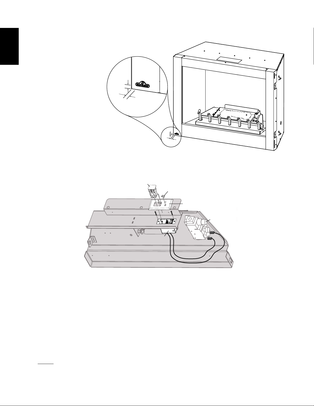
5.4 LOGO PLACEMENT
EN
Remove the backing of the logo supplied. Centre the
logo on the front of the appliance, ½” in from the left
side, as shown.
½"
½"
½"
½"
6.0 OPTIONAL REMOTE INSTALLATION
BATTERY
PACK
TO OPEN
PRESS
SLIDE
SWITCH
BA
T.LOW
FIREPLACEREMOTE
R
EMOTE
OFF
ON
FACEPLATE
VALVE
RECEIVER
REAR BURNER BASE
A. Remove the battery pack from the receiver. Then by pulling down, remove the receiver cover and
slide the receiver into the hole located at the rear of the burner base. Secure using the two screws
provided.
B. Secure the faceplate to the receiver with two of the screws provided.
C. Insert the battery pack (with batteries installed) through the opening in the faceplate and into the
receiver. The battery pack is secured and released with a catch mechanism. Push the receiver into
the catch to secure.
D. Insert the slide switch into its marked position on the faceplate.
E. Replace the existing switch wires connected to the terminals on the valve marked TH/TP and TH
with those running from the receiver.
NOTE: The remote switch on the side of the unit is no longer operational.
W415-2164 / A / 07.21.16
7.0 OPERATION
When lit for the fi rst time, the appliance will emit an odor for a few hours. This is a normal temporary condition
caused by the “burn-in” of paints and lubricants used in the manufacturing process and will not occur again.
After extended periods of non-operation such as following a vacation or a warm weather season, the appliance
may emit a slight odor for a few hours. This is caused by dust particles in the heat exchanger burning off. In
both cases, suffi ciently ventilate the area.
• This appliance is equipped with a pilot which must be lit by hand while following these instructions exactly.
• Before operating smell all around the appliance area for gas and next to the fl oor because some gas is
heavier than air and will settle on the fl oor.
• Use only your hand to turn the gas control knob. Never use tools. If the knob will not turn by hand, do not
try to repair it. Call a qualifi ed service technician. Force or attempted repair may result in a fi re or
explosion.
• Do not use this appliance if any part has been under water. Immediately call a qualifi ed service technician
to inspect the appliance and replace any part of the control system and any gas control which has been
under water.
• Do not use a mobile or land phone.
• If you cannot reach your gas supplier, call the fi re
department.
• Do not try to light any appliance.
A.
B.
C.
Follow “B” in the
above safety information on this label. If you don’t smell gas go to the next step.
D.
E.
F.
G.
for one minute, then release. If pilot does not continue to burn repeat steps 3 through 7.
H.
I.
J.
Remote switch must be in the on position to ignite burner.
A.
WARNING
15
!
IF YOU DO NOT FOLLOW THESE INSTRUCTIONS EXACTLY, A FIRE OR EXPLOSION MAY RESULT
CAUSING PROPERTY DAMAGE, PERSONAL INJURY OR LOSS OF LIFE.
FOR YOUR SAFETY READ BEFORE LIGHTING:
Stop! Read the above safety information on this label.
Turn the gas knob clockwise to off.
Wait fi ve (5) minutes to clear out any gas. If you smell gas including near the fl oor, STOP!
If the appliance is equipped with fl ame adjustment valve turn clockwise to off.
Find pilot located in front of back log.
Turn gas knob counter-clockwise to pilot.
Depress and hold gas knob while lighting the pilot with the push button igniter. Keep knob fully depressed
With pilot lit, turn gas knob counter-clockwise to on.
If equipped with fl ame adjustment valve, push and turn knob to high.
If equipped with remote on-off switch, main burner may not come on when you turn the valve to on or high.
Push in gas control knob slightly and turn clock- wise to off. DO NOT FORCE.
WHAT TO DO IF YOU SMELL GAS:
• Immediately call your gas supplier from a
neighbour’s phone. Follow the gas supplier’s
instructions.
• Turn off all gas to the appliance.
LIGHTING INSTRUCTIONS:
TO TURN OFF GAS:
47.9
EN
W415-2164 / A / 07.21.16
 Loading...