

Napoleon GPV GAS POWER VENT Installation Instructions Manual
INSTALLER: LEAVE THESE INSTRUCTIONS WITH THE APPLIANCE THIS TERMINAL IS SERVING.
CONSUMER: RETAIN THESE INSTRUCTIONS FOR FUTURE REFERENCE. THESE INSTRUCTIONS
ARE TO BE USED IN CONJUNCTION WITH THE APPLIANCE AND PVA INSTRUCTIONS.
INSTALLATION
INSTRUCTIONS
1
EN
CERTIFIED UNDER CANADIAN AND AMERICAN NATIONAL STANDARDS: ANSI Z21.88 CSA 2.33 FOR VENTED GAS FIREPLACE HEATERS
$1'$16,=&6$)259(17('*$6),5(3/$&(6
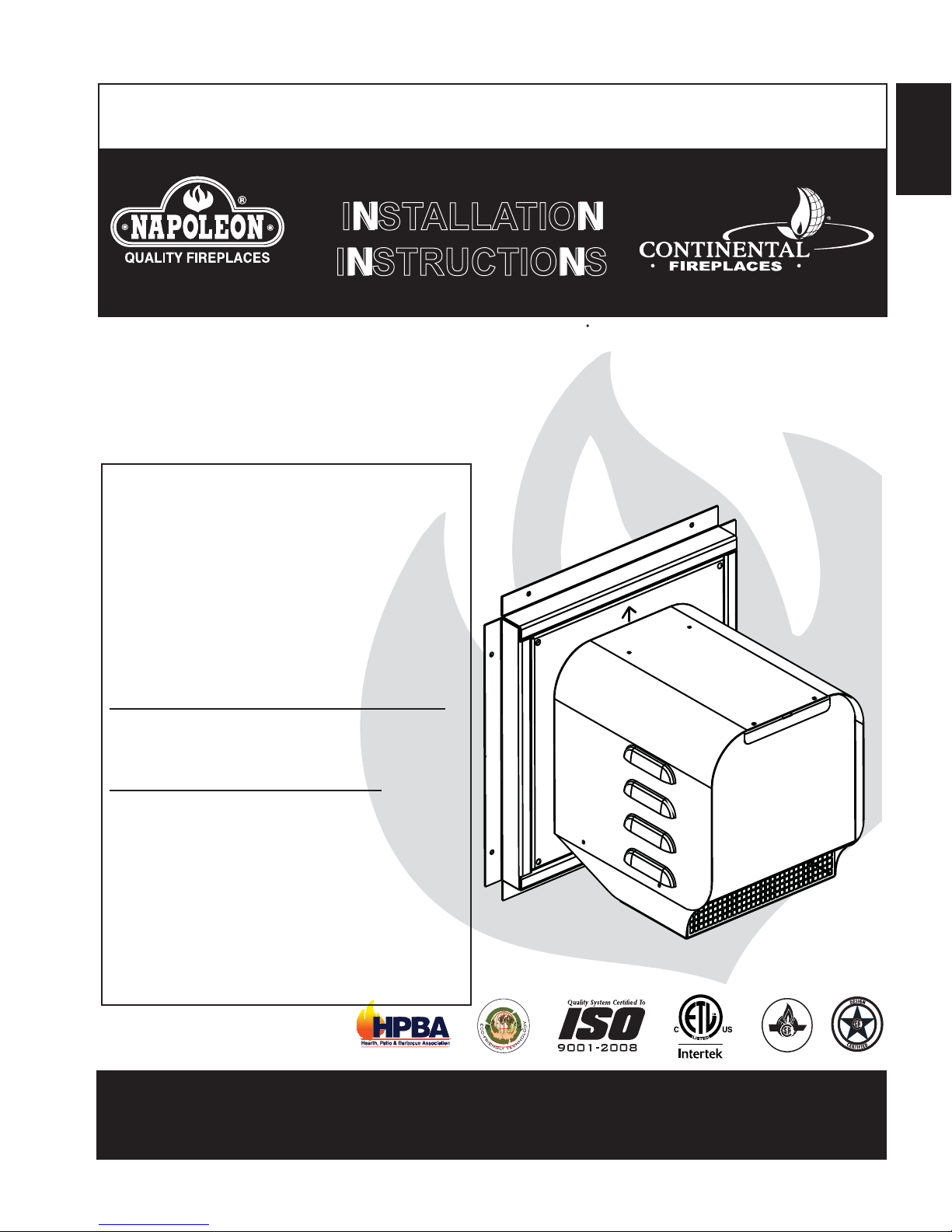
The GPV is a Direct Vent Terminal
GAS POWER
designed to allow installation of
VENT
(GPV)
GENERAL INFORMATION
These Installation Instructions must be used in conjunction
with the appliance and appropriate PVA adapter kit Installation
Instructions. Clearances listed in these Instructions supersede
those in the appliance's Installation Instructions.
Power venting of direct vent appliances may result in the
reduction of efficiencies by as much as ten percent. Consider
this in making any venting and heating decisions in any
installation application.
SELECTING AND INSTALLING THE APPLIANCE
When selecting a gas appliance for use with the GPV, take into
consideration the various requirements and limitations in the
venting installation section for the following models:
Models Equipped with an Intermittent Pilot Ignition (I.P.I.)
It is recommended that the GPV be used with a gas appliance
equipped with an Intermittent Pilot Ignition (I.P.I.). Downward
vertical vent runs are permitted with an I.P.I. system. See
venting section in appropriate PVA Installation Instructions.
Models Equipped with Millivolt/ Standing Pilot
Downward vertical vent runs are not permitted with a standing
pilot system. See venting section in appropriate PVA Installation
Instructions.
INSTALLATION TO BE DONE BY A QUALIFIED INSTALLER
to conform with local codes. In absence of local codes install
to the current National Building Code in Canada or to regional
building codes in the United States. It must be electrically
connected and grounded in accordance with local codes. In
the absence of local codes, use the current CSA C22.1
CANADIAN ELECTRICAL CODE in Canada or the ANSI/NFPA
70 NATIONAL ELECTRIC CODE in the United States.
The GPV operates on 120 VAC 60 HZ electrical service which is
supplied at the firebox junction box.
gas appliances where typical vent
configurations cannot be achieved.
Wolf Steel Ltd., 24 Napoleon Rd., Barrie, ON, L4M 4Y8 Canada /
103 Miller Drive, Crittenden, Kentucky, USA, 41030
ID[ZZZQDSROHRQILUHSODFHVFRPDVN#QDSROHRQRQFD
ZZZFRQWLQHQWDOILUHSODFHVFRPDVN#FRQWLQHQWDOILUHRQFD
CERTIFIED
W415-1160 / 03.06.13

2
TABLE OF CONTENTS
EN
1.0 VENTING 2
1.1 INSTALLATION OVERVIEW 3
1.2 VENT TERMINAL CLEARANCES 4
1.3 VENT LENGTHS 5
1.4 POWER VENT TERMINAL 5
1.4.1 TERMINAL INSTALLATION 5
1.4.2 POWER VENT INSTALLATION 6
1.4.3 INITIAL FIRING PROCEDURES 6
1.4.4 ELECTRICAL CONNECTION 7
1.4.5 HARD WIRING CONNECTION 7
1.4.6 RECEPTACLE WIRING DIAGRAM 7
1.4.7 ELECTRICAL BOX INSTALLATION 8
1.5 RESTRICTOR PLATE INSTALLATION 8
1.6 WIRING DIAGRAM AND INSTALLATION 8
1.6.1 SIT IPI 885 PROFLAME 1 9
1.6.2 SIT IPI PROFLAME 2 10
1.6.3 SIT MILLIVOLT 820 REQUIRING A DOUBLE POLE SWITCH 11
1.6.4 SIT MILLIVOLT 820 NOVA FOR SINGLE POLE SWITCH 12
1.6.5 SIT MILLIVOLT 820 NOVA REMOTE CONTROLLED SYSTEM REQUIRING A DOUBLE POLE SWITCH 13
1.6.6 SIT IPI 880/886 PROFLAME REQUIRING A DOUBLE POLE SWITCH 14
1.6.7 SIT IPI 880/886 FOR SINGLE POLE SWITCH 15
1.6.8 DEXEN IPI 6003-3V REQUIRING A DOUBLE POLE SWITCH 16
1.6.9 DEXEN IPI 6003-3V REQUIRING A SINGLE POLE SWITCH 17
2.0 ADJUSTMENTS 18
2.1 VENTURI ADJUSTMENTS 18
3.0 REPLACEMENTS 18
4.0 TROUBLESHOOTING 19
5.0 NOTES 20
NOTE: Changes, other than editorial, are denoted by a vertical line in the margin.
1.0 VENTING
There are specifi c adaptors and venting requirements for each appliance, refer to your power vent adaptor
leafl et for more information.
For complete installation instructions refer to the following web sites:
Manufacturer Website
Napoleon - English http://www.napoleonfi replaces.com/Tech/installation_manuals/installations.html
Napoleon - French http://www.napoleonfoyers.com/Fireplaces/powervent.html
Continental http://www.continentalfi replaces.com/fi replaces/gas/powervent.html
W415-1160 / 03.06.13
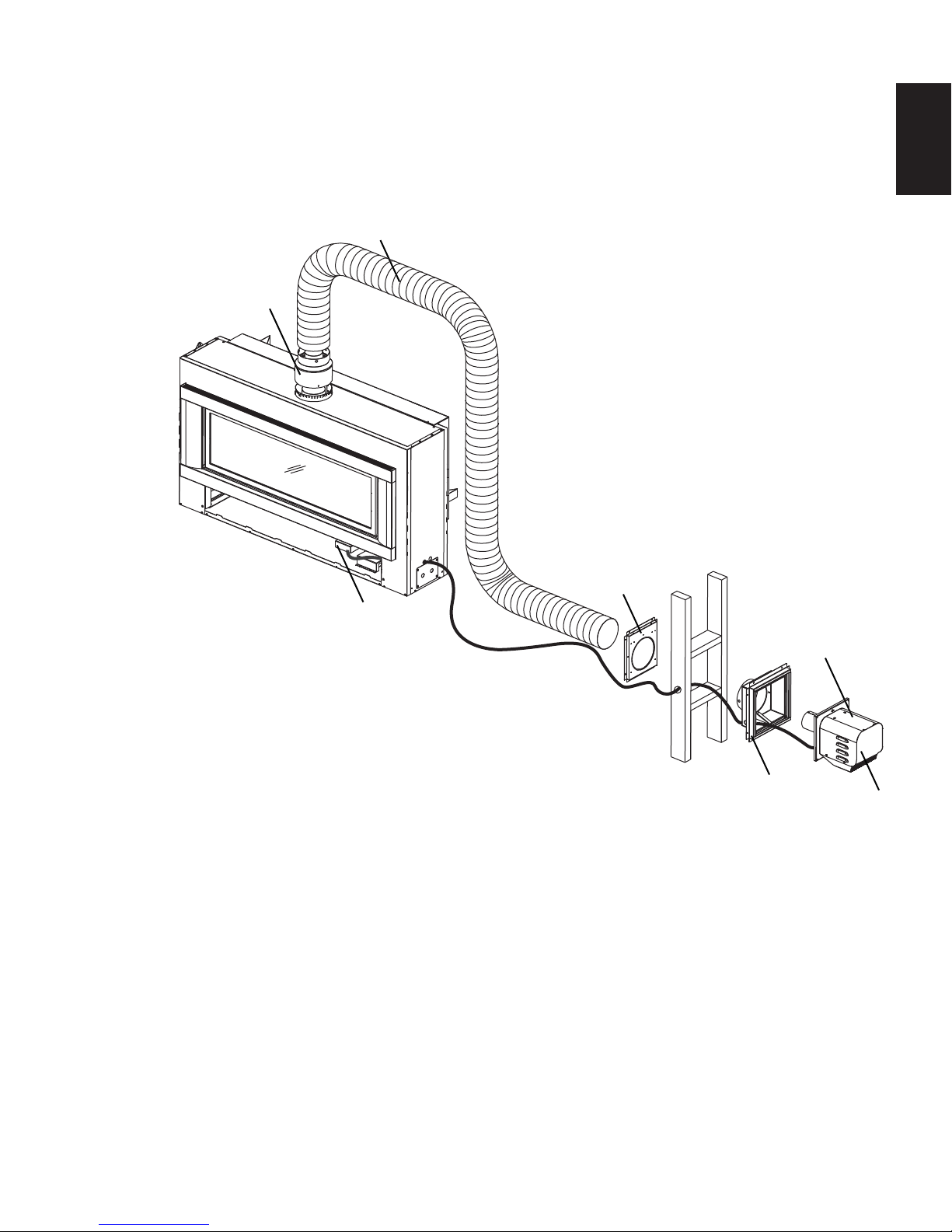
1.1 INSTALLATION OVERVIEW
Reducer, refer to
power vent
adapter kit (PVA)
A typical vent
configuration
for specific venting instructions
where applicable.
3
EN
LHD50 Illustrated
Electrical Box
(velcro to base)
Firestop
Spacer
Gas Power
Vent Terminal
Frame Assembly
Terminal
Access
Cover
W415-1160 / 03.06.13

4
1.2 VENT TERMINAL CLEARANCES
EN
COVERED BALCONY APPLICATIONS ††*
Q
S
R
G
P
A
B
C
D
E
F 0” (0mm) 0” (0mm) Clearance to an outside corner wall.
G
H 3’ (0.9m) 3’ (0.9m)***
I 3’ (0.9m) 3’ (0.9m)*** Clearance to a service regulator vent outlet.
J
K 6’ (1.8m) 3’ (0.9m) Clearance to a mechanical air supply inlet.
L 7’ (2.1m) ‡ 7’ (2.1m)*** Clearance above a paved sidewalk or paved driveway located on public property.
M
N
O 2’ (0.6m) †* 2’ (0.6m) †* Clearance from an adjacent wall including neighbouring buildings.
P 8’ (2.4m) 8’ (2.4m) Roof must be non-combustible without openings.
Q 3’ (0.9m) 3’ (0.9m) See chart for wider wall dimensions.
R 6’ (1.8m) 6’ (1.8m)
S
Δ The terminal shall not be located less than 6 feet (1.8m) under a window that opens on a horizontal plane in a structure with three walls and a roof.
* Recommended to prevent condensation on windows and thermal breakage
** It is recommended to maximize the distance to vinyl clad soffi ts.
*** This is a recommended distance. For additional requirements check local codes.
‡ A vent shall not terminate where it may cause hazardous frost or ice accumulations on adjacent property surfaces..
†† Permitted only if the veranda, porch, or deck is fully open on a minimum of two sides beneath the fl oor.
†* Recommended to prevent recirculation of exhaust products. For additional requirements check local codes.
††* Permitted only if the balcony is fully open on a minimum of one side.
W415-1160 / 03.06.13
INSTALLATIONS
CANADA U.S.A.
12”
(304.8mm)
12”
(304.8mm)
12”
(304.8mm)*
18”
(457.2mm)**
12”
(304.8mm)**
Δ
12”
(304.8mm)
9” (228.6mm)
Δ
12”
(304.8mm)*
18”
(457.2mm)**
12”
(304.8mm)**
0” (0mm) 0” (0mm)
2” (50.8mm) 2” (50.8mm)
12”
(304.8mm)
12”
(304.8mm)††
12”
(304.8mm)
12”
(304.8mm)
9” (228.6mm)
12”
(304.8mm)***
12”
(304.8mm)
12”
(304.8mm)
Q
= 3 feet
MIN
(0.9m)
R
= 2 x
MAX
Q
ACTUAL
R
MAX
IHHW
(4.6m)
Clearance above grade, veranda porch, deck or balcony.
Clearance to windows or doors that open.
Clearance to permanently closed windows.
Vertical clearance to ventilated soffi ts located above the terminal within a horizontal distance of
2’ (0.6m) from the center line of the terminal.
Clearance to unventilated soffi t.
Clearance to an inside non-combustible corner wall or protruding non-combustible obstructions (chimney,
etc.).
Clearance to an inside combustible corner wall or protruding combustible obstructions (vent chase,
etc.).
Clearance to each side of the center line extended above the meter / regulator assembly to a
maximum vertical distance of 15’ (4.6m).
Clearance to a non-mechanical air supply inlet to the building or a combustion air inlet to any other
appliance.
Clearance under a veranda, porch or deck.
Clearance above the roof.
See chart for deeper wall dimensions. The terminal shall not be installed on any wall that has an
opening between the terminal and the open side of the structure.
Clearance under a covered balcony
12.2D

1.3 VENT LENGTHS
DETERMINE
THE
CORRECT
HEIGHT
5
REFER TO POWER VENT ADAPTER KIT (PVA) FOR SPECIFIC VENTING INSTRUCTIONS.
NOTE: If equipped, ACS switch must be disabled if there is any downward venting. Downward venting is not
allowed with appliances that use standing pilots.
1.4 POWER VENT TERMINAL
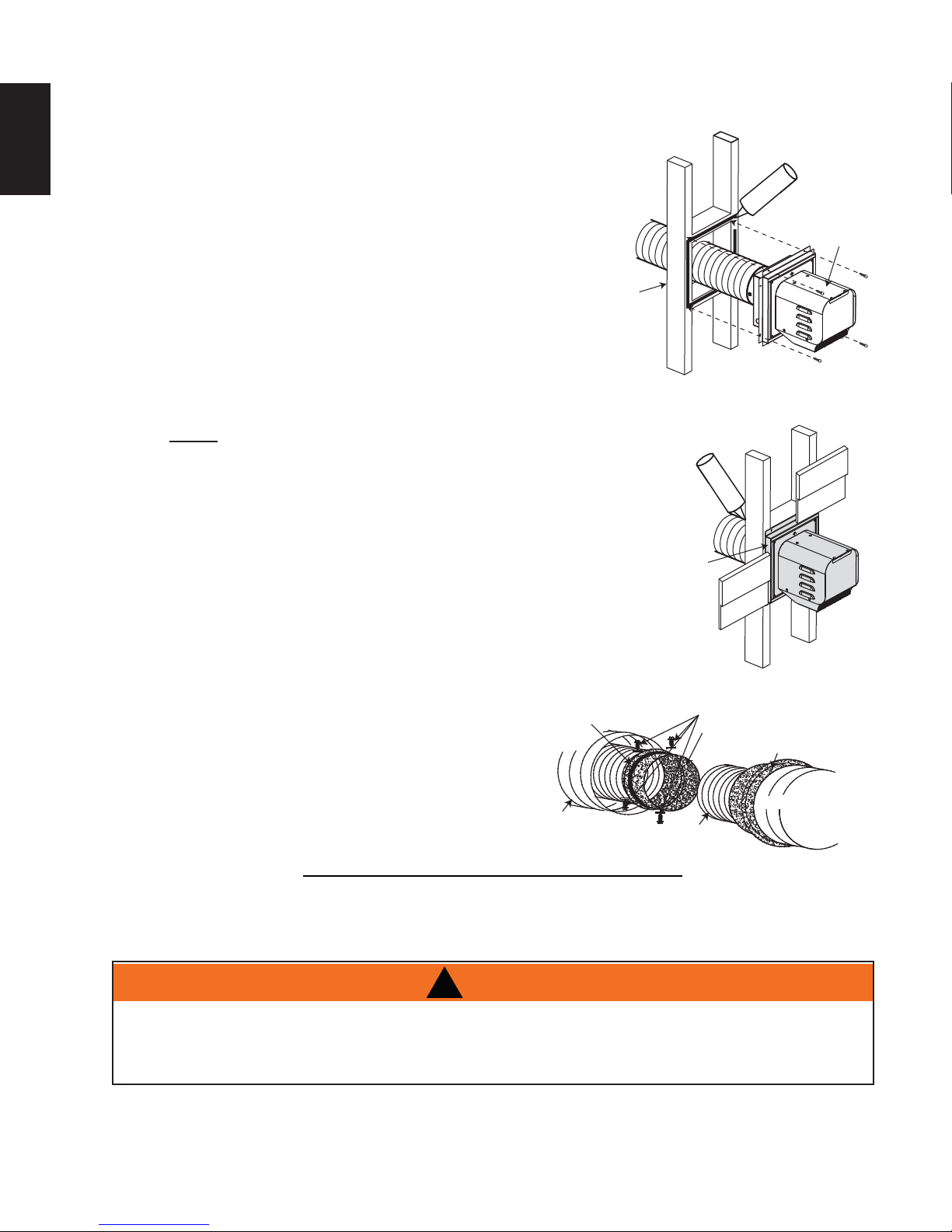
1.4.1 TERMINAL INSTALLATION
This application occurs when venting through an exterior wall. Having determined the correct
height for the terminal location, cut and frame a hole in the exterior wall as illustrated to
accommodate the GPV.
A. Remove the electrical access plate from the frame assembly, then
remove the knock out from this plate.
B. Insert the wiring through the electrical access plate and engage the
conduit bushing. Re-secure this plate. NOTE: The GPV includes a
20 foot (6.1m) wire harness cable. If this cable does not reach
the appliance, then it may be cut and a splice added. These
connections must conform with local codes or, in the absence of
local codes, use the current CSA C22.1 Canadian Electrical Code in
Canada or the ANSI/NFPA 70 National Electrical Code in the United
States.
11 1/4”
(285.8mm)
EN
10 1/4”
(260.4mm)
C. Remove terminal access cover, see “INSTALLATION OVERVIEW” for
location and route cable through terminal.
D. Assemble gas power vent terminal to frame assembly.
E. Connect the male and female connectors.
F. Replace terminal access cover.
NOTE: Where possible, it is strongly recommended to have an access panel inside the building for
servicing the unit.
MALE MOLEX
ELECTRICAL
ACCESS PLATE
CONNECTOR
TERMINAL
FEMALE
MOLEX
CONNECTOR
20.4A
W415-1160 / 03.06.13
6
1.4.2 POWER VENT INSTALLATION
EN
A. Stretch the inner fl ex pipe to the required length taking
into account the additional length needed for the
fi nished wall surface. Slip the vent pipe a minimum of
3” (76.2mm) over the inner sleeve of the terminal and
secure with 3 #8 screws. Apply a heavy bead of the
high temperature sealant W573-0007 Mill Pac (not
supplied).
B. Using the outer fl ex pipe, slide over the outer
combustion air sleeve of the terminal and secure with
3 #8 screws. Seal using high temperature sealant
W573-0002 (not supplied).
C.
D. Route venting through framed opening and fi restop spacer to the
E. The terminal mounting plate may be recessed into the exterior
Apply a bead of caulking (not supplied) to the framed
opening and secure the terminal. Ensure the arrows
stamped into the frame assembly are pointing upwards.
NOTE: For fi restop spacer installation instructions, see PVA
kit or the appliance Installation Manual.
appliance.
wall or siding no greater than the depth of its return fl ange.
FIRESTOP
SPACER
CAULKING
TERMINAL
#10 X 2”
SCREWS
HIGH
TEMPERATURE
SEALANT
RETURN
FLANGE
F. If more vent pipe needs to be used to reach the appliance, couple
them together as illustrated. The vent system must be supported
approximately every 3 feet (0.9m) for both vertical and horizontal
runs. Use noncombustible strapping to maintain the minimum
clearance to combustibles.
G. Install the reducer (if required) or vent and
properly secure and seal to the unit using high
temperature sealant W573-0007 Mill Pac (not
supplied).
1.4.3 INITIAL FIRING PROCEDURES
ALWAYS LIGHT THE PILOT WHETHER FOR THE FIRST TIME OR IF THE GAS SUPPLY HAS RUN
OUT WITH THE GLASS DOOR OPENED OR REMOVED. PURGE SHOULD BE PERFORMED BY A
QUALIFIED SERVICE TECHNICIAN. ASSURE THAT A CONTINUOUS GAS FLOW IS AT THE BURNER
BEFORE CLOSING THE DOOR. ENSURE ADEQUATE VENTILATION.
HI-TEMP
SEALANT
OUTER
FLEX PIPE
!
WARNING
#8 X 1/2” SELF DRILLING
SCREWS & WASHERS
INNER COUPLER
OUTER COUPLER
OUTER
FLEX PIPE
INNER
FLEX PIPE
23.6A
In some instances the system may not light pilot/burner with the door open/removed. Partially blocking the
exhaust fl ue collar will allow the safety pressure switch to activate and allow gas fl ow to the pilot during the
initial test fi ring.
W415-1160 / 03.06.13
 Loading...