

Napoleon GL18N, GL24N, GL24P, GL30P, GL30N Installation And Operating Instructions Manual
...
INSTALLER: LEAVE THIS MANUAL WITH THE APPLIANCE.
CONSUMER: RETAIN THIS MANUAL FOR FUTURE REFERENCE.
INSTALLATION AND
OPERATING INSTRUCTIONS
CERTIFIED UNDER: ANSI Z21.60-2002 / CSA 2.26-2002 DECORATIVE GAS APPLIANCES FOR INSTALLATION IN SOLID-FUEL BURNING APPLIANCES
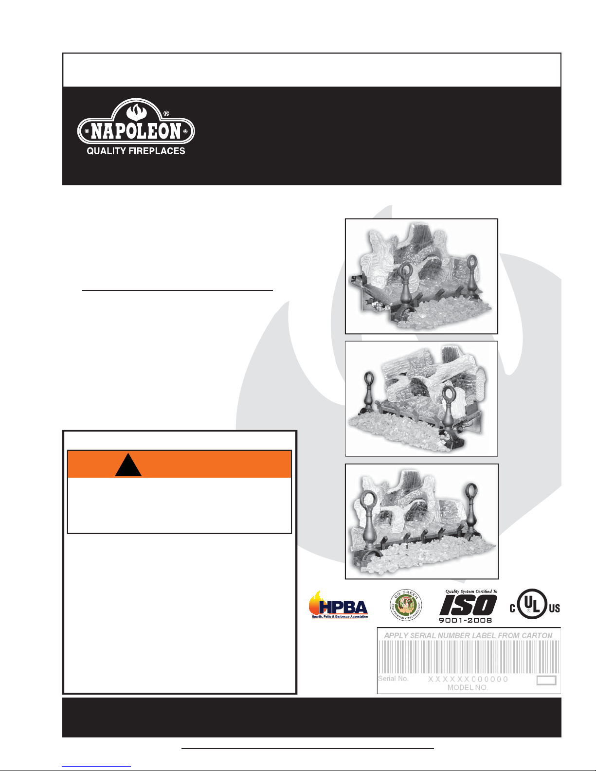
GL18N, GL24N,
GL30N
NATURAL GAS
1
GL18P, GL24P,
GL30P
PROPANE
CERTIFIED FOR CANADA AND UNITED STATES USING ANSI/CSA METHODS.
SAFETY INFORMATION
!
WARNING
If the information in these instructions are
not followed exactly, a fi re or explosion
may result causing property damage,
personal injury or loss of life.
- Do not store or use gasoline or other fl ammable
vapors and liquids in the vicinity of this or any
other appliance.
- WHAT TO DO IF YOU SMELL GAS:
• Do not try to light any appliance.
• Do not touch any electrical switch; do
not use any phone in your building.
• Immediately call your gas supplier from
a neighbour’s phone. Follow the gas
supplier’s instructions.
• If you cannot reach your gas supplier,
call the fi re department.
- Installation and service must be performed by a
qualifi ed installer, service agency or the supplier.
GL18
GL24
GL30
Wolf Steel Ltd., 24 Napoleon Rd., Barrie, ON, L4M 4Y8 Canada /
Phone (705)721-1212 • Fax (705)722-6031 • www.napoleonfi replaces.com • ask@napoleonproducts.com
$10.00
103 Miller Drive, Crittenden, Kentucky, USA, 41030
1.4A
W415-0472 / D / 11.24.10

2
TABLE OF CONTENTS
1.0 INSTALLATION OVERVIEW 2
2.0 INTRODUCTION 3
2.1 GENERAL INSTRUCTIONS 4
2.2 GENERAL INFORMATION 5
2.3 MINIMUM APPLIANCE SIZE 5
2.4 RATING PLATE 5
3.0 INSTALLATION 6
3.1 GAS PIPING 6
3.2 DAMPER STOP INSTALLATION 7
4.0 FINISHING 8
4.1 ANDIRON AND GRATE ASSEMBLY 8
4.2 REMOTE INSTALLATION 8
4.3 LOG PLACEMENT 9
4.4 MEDIA 10
4.5 LOGO PLACEMENT 10
5.0 OPERATING INSTRUCTIONS 11
5.1 LIGHTING INSTRUCTIONS 11
6.0 OPERATION 12
7.0 ADJUSTMENTS 13
7.1 PILOT BURNER ADJUSTMENT 13
7.2 VENTURI ADJUSTMENT 13
7.3 FLAME ADJUSTMENT 14
7.4 FLAME CHARACTERISTICS 14
8.0 MAINTENANCE 14
9.0 REPLACEMENTS 15
10.0 TROUBLE SHOOTING 17
11.0 WARRANTY 19
12.0 SERVICE HISTORY 20
NOTE: Changes, other than editorial, are denoted by a vertical line in the margin.
1.0 INSTALLATION OVERVIEW
Logs, see “LOG PLACEMENT”
section.
Andiron, see “ANDIRON AND
GRATE ASSEMBLY” section.
Rating Plate, see “RATING
PLATE INFORMATION”
section.
W415-0472 / D / 11.24.10
Media, see “MEDIA” section.
2.0 INTRODUCTION
• THIS APPLIANCE IS HOT WHEN OPERATED AND CAN CAUSE SEVERE BURNS IF CONTACTED.
• ANY CHANGES OR ALTERATIONS TO THIS APPLIANCE OR IT’S CONTROLS CAN BE
DANGEROUS AND IS PROHIBITED.
• Do not operate appliance before reading and understanding operating instructions. Failure to operate
appliance according to operating instructions could cause fi re or injury.
• Risk of fi re or asphyxiation do not operate appliance with fi xed glass removed.
• Do not connect 110 volts to the control valve.
• Risk of burns. The appliance should be turned off and cooled before servicing.
• Do not install damaged, incomplete or substitute components.
• Risk of cuts and abrasions. Wear protective gloves and safety glasses during installation. Sheet metal
edges may be sharp.
• Do not burn wood or other materials in this appliance.
• Children and adults should be alerted to the hazards of high surface temperature and should stay away
to avoid burns or clothing ignition. Toddlers, young children and others may be susceptible to accidental
contact burns. A physical barrier is recommended if there are at risk individuals in the house. To restrict
access to an appliance or stove, install an adjustable safety gate to keep toddlers, young children and
other at risk individuals out of the room and away from hot surfaces.
• Clothing or other fl ammable material should not be placed on or near the appliance.
• Due to high temperatures, the appliance should be located out of traffi c and away from furniture and
draperies.
• Ensure you have incorporated adequate safety measure to protect infants/toddlers from touching hot
surfaces.
• Even after the appliance is out, the glass and/or screen will remain hot for an extended period of time.
• Check with your local hearth specialty dealer for safety screens and hearth guards to protect children
from hot surfaces. These screens and guards must be fastened to the fl oor.
• Any safety screen or guard removed for servicing must be replaced prior to operating the appliance.
• This appliance is a vented gas-fi red appliance. Do not burn wood or other materials in this appliance.
• It is imperative that the control compartments, burners and circulating blower and its passageway in the
appliance and venting system are kept clean. The appliance and its venting system should be inspected
before use and at least annually by a qualifi ed service person. More frequent cleaning may be required
due to excessive lint from carpeting, bedding material, etc. The appliance area must be kept clear and
free from combustible materials, gasoline and other fl ammable vapors and liquids.
• Under no circumstances should this appliance be modifi ed.
• This appliance must not be connected to a chimney fl ue pipe serving a separate solid fuel burning
appliance.
• Do not use this appliance if any part has been under water. Immediately call a qualifi ed service
technician to inspect the appliance and to replace any part of the control system and any gas control
which has been under water.
• Do not operate the appliance with the glass door removed, cracked or broken. Replacement of the glass
should be done by a licensed or qualifi ed service person.
• Do not strike or slam shut the appliance glass door.
• Only doors / optional fronts certifi ed with the unit are to be installed on the appliance.
• Keep the packaging material out of reach of children and dispose of the material in a safe manner. As
with all plastic bags, these are not toys and should be kept away from children and infants.
• As with any combustion appliance, we recommend having your appliance regularly inspected and
serviced as well as having a Carbon Monoxide Detector installed in the same area to defend you and
your family against Carbon Monoxide.
• Ensure clearances to combustibles are maintained when building a mantel or shelves above the
appliance. Elevated temperatures on the wall or in the air above the appliance can cause melting,
discolouration or damage to decorations, a T.V. or other electronic components.
!
WARNING
3
3.16B
W415-0472 / D / 11.24.10
4
2.1 GENERAL INSTRUCTIONS
ALWAYS LIGHT THE PILOT WHETHER FOR THE FIRST TIME OR IF THE GAS SUPPLY HAS RAN OUT,
WITH THE GLASS DOOR OPENED OR REMOVED.
PROVIDE ADEQUATE CLEARANCE FOR SERVICING AND OPERATING THE APPLIANCE.
NEVER OBSTRUCT THE FRONT OPENING OF THE APPLIANCE.
OBJECTS PLACED IN FRONT OF THE APPLIANCE MUST BE KEPT A MINIMUM OF 48” FROM THE
SURFACES AROUND AND ESPECIALLY ABOVE THE APPLIANCE CAN BECOME HOT. AVOID CONTACT
WHEN THE APPLIANCE IS OPERATING.
HIGH PRESSURE WILL DAMAGE VALVE. DISCONNECT GAS SUPPLY PIPING BEFORE PRESSURE TESTING GAS
LINE AT TEST PRESSURES ABOVE 1/2 PSIG. CLOSE THE MANUAL SHUT-OFF VALVE BEFORE PRESSURE
TESTING GAS LINE AT TEST PRESSURES EQUAL TO OR LESS THAN 1/2 PSIG.
USE ONLY WOLF STEEL APPROVED OPTIONAL ACCESSORIES AND REPLACEMENT PARTS WITH THIS APPLIANCE.
USING NON-LISTED ACCESSORIES (BLOWERS, DOORS, LOUVRES, TRIMS, GAS COMPONENTS, VENTING
COMPONENTS, ETC.) COULD RESULT IN A SAFETY HAZARD AND WILL VOID THE WARRANTY AND CERTIFICATION.
!
WARNING
PROVIDE ADEQUA TE VENTILA TION.
FRONT FACE OF THE UNIT.
FIRE RISK. EXPLOSION HAZARD.
Thoroughly clean the chimney, fl ue and existing appliance before installing the new appliance into it. Do not
burn solid fuels in any appliance that is equipped with this gas log set.
The installation of this appliance must conform with local
codes or in the absence of local codes, it must conform to
ANSI Z.223.1 or the CAN/CGA B149.
We suggest that our gas
hearth products be installed
and serviced by profes-
Do not operate appliance in the presence of gasoline or
other fl ammable liquids and vapours. Keep area clear of
other combustible materials. The appliance and its shut off
must be disconnected from the gas supply piping system
before any pressure testing of the system is done.
Installation practices vary from region to region and it is important to know the specifi cs that apply to your area,
For example: in Massachusetts State:
• This product must be installed by a licensed plumber or gas fi tter when installed within the
commonwealth of Massachusetts.
• The appliance damper must be removed or welded in the open position prior to installation of a
appliance
• insert or gas log.
• The appliance off valve must be a “T” handle gas cock.
• The fl exible connector must not be longer than 36 inches.
• The appliance is not approved for installation in a bedroom or bathroom unless the appliance is a
direct vent sealed combustion product.
• A carbon monoxide detector is required in all rooms containing gas fi red appliances.
www.nficertified.org
sionals who are certified in
the U.S. by the National
®
Fireplace Institute
(NFI) as
NFI Gas Specialists.
No external electricity (110 volts or 24 volts) is required for the gas system operation.
W415-0472 / D / 11.24.10
2.2 GENERAL INFORMATION
RIA
APPLIANCE
24 NAPOLEON ROAD.
THIS APPLIANCE MUST NOT BE INSTALLED IN A BEDROOM OR BATHROOM.
THE APPLIANCE IS ONLY FOR USE WITH THE TYPE OF GAS INDICATED ON THE RATING PLATE.
THIS APPLIANCE IS NOT CONVERTIBLE FOR USE WITH OTHER GASES.
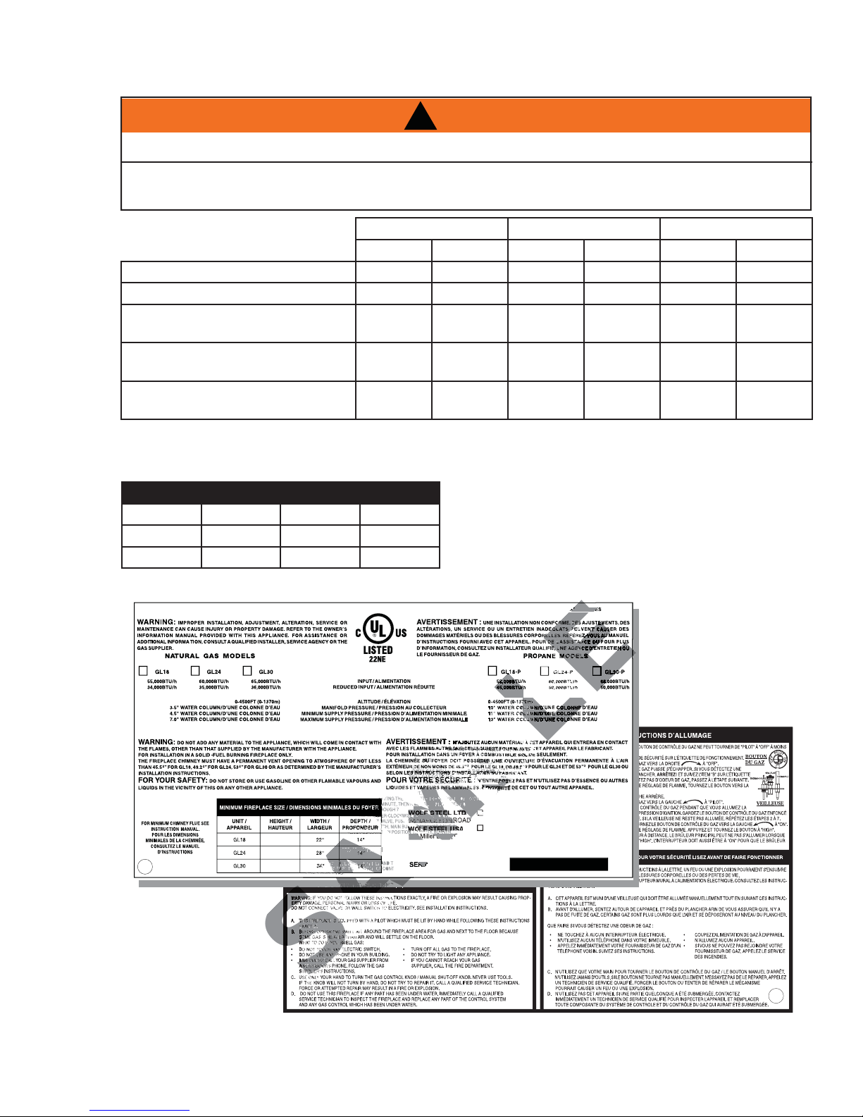
Altitude (FT) 0-4,500 0-4,500 0-4,500 0-4,500 0-4,500 0-4,500
Max input (BTU/HR) 55,000 55,000 60,000 60,000 65,000 65,000
Min Inlet Gas Supply Pressure 4.5“ Water
Max Inlet Gas Supply Pressure 7“ Water
Manifold Pressure (Under Flow
Conditions)
!
WARNING
GL18 GL24 GL30
NG LP NG LP NG LP
Column
Column
3.5“ Water
Column
11“ Water
Column
13“ Water
Column
10“ Water
Column
4.5“ Water
Column
7“ Water
Column
3.5“ Water
Column
11“ Water
Column
13“ Water
Column
10“ Water
Column
4.5“ Water
Column
7“ Water
Column
3.5“ Water
Column
5
11“ Water
Column
13“ Water
Column
10“ Water
Column
2.3 MINIMUM APPLIANCE SIZE
LOG SET HEIGHT WIDTH DEPTH
GVFL18 18” 22” 14”
GVFL24 20” 28” 14”
GVFL30 22” 34” 14”
2.4 RATING PLATE
CERTIFIED UNDER / HOMOLOGUE SELON LES NORMES: ANSI Z21.60b-2004 CGA 2.26b-2004, DECORATIVE APPLIANCE FOR INSTALLATION IN SOLID-FUEL BURNING APPLIANCES
REFERENCE # W/N 15987
18”
18”
18”
Each gas log set must be installed into an appliance cavity
with a minimum size.
Refer to the table to determine the appropriate minimum
appliance size.
THE RATING PLATE
IS CHAINED TO THE
PIEZO IGNITOR
BRACKET AND
SHOULD BE TUCKED
UNDER THE ENTIRE
ASSEMBLY
24 NAPOLEON ROAD. BARRIE, ONTARIO L4M 4Y8 CANADA
103 Miller Drive, Crittenden, Kentucky, USA, 41030
SERIAL NUMBER/NO. DE SERIE: GL
W385-0301_E
This rating plate is for reference only. Refer to the rating plate on the appliance for accurate information.
W415-0472 / D / 11.24.10
6
3.0 INSTALLATION
The appliance and gas logs function as a system. If the appliance is not drafting properly and spilling into the
room (check with a match or a smoke stick), reposition the damper clamp until a positive draft is obtained
by opening the damper. If negative pressure in home prevents having a positive draft, consult an air quality
specialist.
3.1 GAS PIPING
DO NOT CONNECT EITHER THE WALL SWITCH, THERMOSTAT OR GAS VALVE TO ELECTRICITY
This appliance must be isolated from the gas supply piping system by closing the individual manual shut off
valve during any pressure testing of the gas supply piping system at test pressure equal to or less than ½ psi
(3.5 kPa)
!
WARNING
(110 VOLTS).
A. Centre the appliance in the fi replace opening, making
sure the appliance has enough room behind it for the
gas line to run behind the log set under the log support.
B. Route the gas line and sizing using piping ½” diameter
or greater to allow the full volume of gas to the
appliance. The routing of the gas line has to be done to
local and / or national codes.
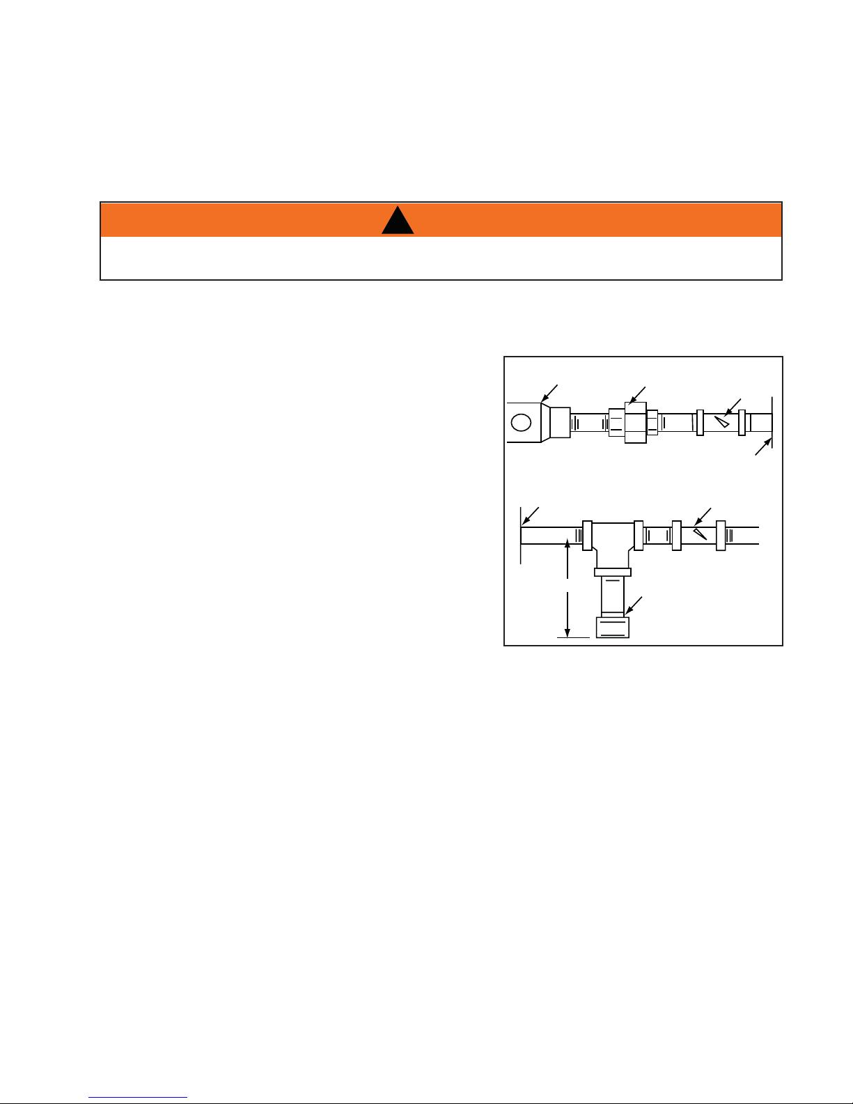
C. When rigid pipe is used an ANSI approved manual shut
off and a union must be installed upstream within the
appliance cavity.
D. To ensure the appliance operates reliably install a
sediment trap upstream of the appliance within the
structures of the piping system.
E. When using propane, a regulator must be used between
the tank and the outside wall of the house to ensure the line pressure does not exceed 14” w.c.
F. Check gas connections with a gas detection device to test for leaks in the system. Soapy water
mixture can also be used to check for leaks.
G. Once all the gas connections are tested for leaks, start the appliance. Follow the lighting instructions
to ensure the appliance is working properly before fi nishing.
Regulator
Appliance
3"
Union
Sediment
Trap
Manual
Shut-Off
Valve
Appliance
Wall
Shut-Off
Key
W415-0472 / D / 11.24.10
 Loading...