

Napoleon GDS60N, GS60N, GS60P, GDS60P Installation And Operating Instrictions
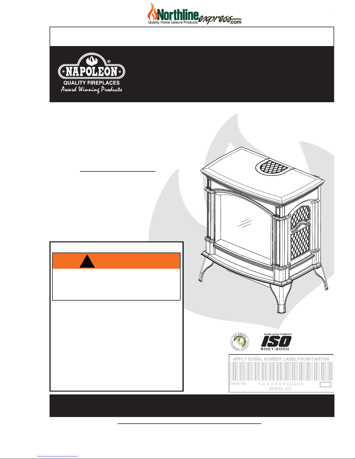
INSTALLER: LEAVE THIS MANUAL WITH THE APPLIANCE.
NorthlineExpress.com
http://www.northlineexpress.com
Toll-Free 1-866-667-8454
CONSUMER: RETAIN THIS MANUAL FOR FUTURE REFERENCE.
OPERATING INSTRUCTIONS
CERTIFIED UNDER CANADIAN AND AMERICAN NATIONAL STANDARDS, CSA 2.33, ANSI Z21.88 FOR VENTED GAS FIREPLACE HEATERS
GDS60N & GS60N
NATURAL GAS
1
INSTALLATION AND
GDS60P & GS60P
PROPANE GAS
CERTIFIED FOR CANADA AND UNITED STATES USING ANSI/CSA METHODS.
SAFETY INFORMATION
!
WARNING
If the information in these instructions are
not followed exactly, a fi re or explosion
may result causing property damage,
personal injury or loss of life.
- Do not store or use gasoline or other fl ammable
vapors and liquids in the vicinity of this or any
other appliance.
- WHAT TO DO IF YOU SMELL GAS:
• Do not try to light any appliance.
• Do not touch any electrical switch; do not use
any phone in your building.
• Immediately call your gas supplier from a
neighbour’s phone. Follow the gas supplier’s
instructions.
• If you cannot reach your gas supplier, call the
fi re department.
- Installation and service must be performed by a
qualifi ed installer, service agency or the supplier.
SHOWN WITH OPTIONAL
TRIVET
Phone (705)721-1212 • Fax (705)722-6031 • www.napoleonfi replaces.com • ask@napoleon.on.ca
$10.00
Wolf Steel Ltd., 24 Napoleon Rd., Barrie, ON, L4M 4Y8 Canada /
103 Miller Drive, Crittenden, Kentucky, USA, 41030
1.2
W415-0788 / 05.15.09

2
NorthlineExpress.com
http://www.northlineexpress.com
Toll-Free 1-866-667-8454
TABLE OF CONTENTS
1.0 INTRODUCTION 3
1.1 WARRANTY 4
1.2 DIMENSIONS 5
1.3 GENERAL INSTRUCTIONS 5
1.4 GENERAL INFORMATION 6
1.5 CARE OF GLASS 7
1.6 SHIPPING BRACKET 7
2.0 VENTING - MODEL GDS60 8
2.1 VENTING LENGTHS AND AIR TERMINAL LOCATIONS 9
2.2 TYPICAL VENT INSTALLATIONS 10
2.3 SPECIAL VENT INSTALLATIONS 12
2.4 CORNER INSTALLATION 12
2.5 VENT TERMINAL CLEARANCES 13
2.6 VENTING APPLICATION FLOW CHART 14
2.7 DEFINITIONS 15
2.8 ELBOW VENT LENGTH VALUES 15
2.9 TOP EXIT HORIZONTAL TERMINATION 16
2.10 TOP EXIT HORIZONTAL TERMINATION 17
2.11 REAR EXIT HORIZONTAL TERMINATION 18
2.12 TOP OR REAR EXIT VERTICAL TERMINATION 20
3.0 INSTALLATION PREPARATION - MODEL GDS60 22
3.1 ORIFICE REPLACEMENT 22
3.2 CHANGING A TOP VENT TO A REAR VENT 23
4.0 INSTALLATION 24
4.1 MINIMUM CLEARANCE TO COMBUSTIBLES 24
4.2 WALL AND CEILING PROTECTION 25
4.2.1 HORIZONTAL INSTALLATION 25
4.2.2 VERTICAL INSTALLATION 26
4.2.3 HORIZONTAL AIR TERMINAL INSTALLATION - MODEL GDS60 26
4.2.4 VERTICAL AIR TERMINAL INSTALLATION - MODEL GDS60 27
4.3 APPLIANCE VENT CONNECTION - MODEL GDS60 28
4.4 MOBILE HOME INSTALLATION - MODEL GDS60 28
4.5 GAS INSTALLATION 28
4.6 OPTIONAL WALL SWITCH / THERMOSTAT 28
4.7 RATING PLATE 29
4.8 B-VENT SPECIFICS - MODEL GS60 29
4.8.1 CHIMNEY INSTALLATION 29
4.8.2 INSTALLING "B" VENT 30
4.8.3 COMBUSTION AIR 30
4.8.4 ADDING VENT SECTIONS 31
4.8.5 INSTALLING FLASHING AND STORM COLLAR 31
5.0 FINISHING 32
5.1 LOGO PLACEMENT 32
5.2 SWITCH AND BRACKET INSTALLATION 32
5.3 FRONT CAST REMOVAL 33
5.4 GLASS DOOR INSTALLATION AND REMOVAL 33
5.5 GLASS / DOOR REPLACEMENT 33
5.6 LOG PLACEMENT 34
6.0 OPERATION 35
6.1 OPERATING INSTRUCTIONS 35
6.2 OPERATING INSTRUCTIONS - FOR YOUR SAFETY READ BEFORE OPERATING 36
6.3 LIGHTING INSTRUCTIONS 36
7.0 WIRING DIAGRAM 37
8.0 BLOWER INSTALLATION 38
9.0 ADJUSTMENT 38
9.1 PILOT BURNER ADJUSTMENT 38
9.2 VENTURI ADJUSTMENT 39
9.3 FLAME CHARACTERISTICS 39
9.4 RESTRICTING VERTICAL VENTS - MODEL GDS60 39
10.0 MAINTENANCE 39
11.0 REPLACEMENTS 40
12.0 TROUBLE SHOOTING 44
13.0 SERVICE HISTORY 46
14.0 NOTES 47
NOTE: Changes, other than editorial, are denoted by a vertical line in the margin.
W415-0788 / 05.15.09

1.0 INTRODUCTION
NorthlineExpress.com
http://www.northlineexpress.com
Toll-Free 1-866-667-8454
• Do not operate heater before reading and understanding operating instructions. Failure to operate heater
according to operating instructions could cause fi re or injury.
• Risk of fi re or asphyxiation do not operate heater with fi xed glass removed.
• Do not connect 110 volts to the control valve.
• Risk of burns. The heater should be turned off and cooled before servicing.
• Do not install damaged, incomplete or substitute components.
• Risk of cuts and abrasions. Wear protective gloves and safety glasses during installation. Sheet metal
edges may be sharp.
• Do not burn wood or other materials in this heater.
• Young children should be carefully supervised when they are in the same room as the appliance. Tod-
dlers, young children and others may be susceptible to accidental contact burns. A physical barrier is
recommended if there are at risk individuals in the house. To restrict access to an appliance or stove,
install an adjustable safety gate to keep toddlers, young children and other at risk individuals out of the
room and away from hot surfaces.
• Clothing or other fl ammable material should not be placed on or near the heater.
• Due to high temperatures, the heater should be located out of traffi c and away from furniture and
draperies.
• Ensure you have incorporated adequate safety measure to protect infants/toddlers from touching hot
surfaces.
• Even after the heater is out, the glass and/or screen will remain hot for an extended period of time.
• Check with your local hearth specialty dealer for safety screens and hearth guards to protect children
from hot surfaces. These screens and guards must be fastened to the fl oor.
• Any safety screen or guard removed for servicing must be replaced prior to operating the heater.
• It is imperative that the control compartments, burners and circulating blower and its passageway in the
heater and venting system are kept clean. The heater and its venting system should be inspected before
use and at least annually by a qualifi ed service person. More frequent cleaning may be required due to
excessive lint from carpeting, bedding material, etc. The heater area must be kept clear and free from
combustible materials, gasoline and other fl ammable vapors and liquids.
• Under no circumstances should this heater be modifi ed.
• This heater must not be connected to a chimney fl ue pipe serving a separate solid fuel burning
appliance.
• Do not use this heater if any part has been under water. Immediately call a qualifi ed service technician
to inspect the heater and to replace any part of the control system and any gas control which has been
under water.
• Do not operate the heater with the glass door removed, cracked or broken. Replacement of the glass
should be done by a licensed or qualifi ed service person.
• Do not strike or slam shut the heater glass door.
• When equipped with pressure relief doors must be kept closed while the heater is operating to prevent
exhaust fumes containing carbon monoxide, from entering into the home. Temperatures of the exhaust
escaping through these openings can also cause the surrounding combustible materials to overheat and
catch fi re.
• When equipped with pressure relief doors, they must be kept closed while the heater is operating to
prevent exhaust fumes containing carbon monoxide, from entering into the home. Temperatures of the
exhaust escaping through these openings can also cause the surrounding combustible materials to
overheat and catch fi re.
• Only doors / optional fronts certifi ed with the unit are to be installed on the appliance.
• Keep the packaging material out of reach of children and dispose of the material in a safe manner. As
with all plastic bags, these are not toys and should be kept away from children and infants.
• As with any combustion appliance, we recommend having your appliance regularly inspected and
serviced as well as having a Carbon Monoxide Detector installed in the same area to defend you and
your family against Carbon Monoxide.
!
WARNING
3
3.2
W415-0788 / 05.15.09

4
NorthlineExpress.com
http://www.northlineexpress.com
Toll-Free 1-866-667-8454
1.1 WARRANTY
NAPOLEON® products are manufactured under the strict Standard of the world recognized ISO 9001 : 2000
NAPOLEON® products are designed with superior components and materials assembled by trained
craftsmen who take great pride in their work. The burner and valve assembly are leak and test-fi red at a
quality test station. The complete heater is again thoroughly inspected by a qualifi ed technician before
packaging to ensure that you, the customer, receives the quality product that you expect from NAPOLEON®.
NAPOLEON® GAS FIREPLACE PRESIDENT’S LIFETIME LIMITED WARRANTY
The following materials and workmanship in your new NAPOLEON® gas heater are warranted against
defects for as long as you own the heater. This covers: combustion chamber, heat exchanger, stainless
steel burner, phazer™ logs and embers, rocks, ceramic glass (thermal breakage only), gold plated parts
against tarnishing, porcelainized enameled components and aluminum extrusion trims.*
Electrical (110V and millivolt) components and wearable parts such as blowers, gas valves, thermal switch,
switches, wiring, remote controls, ignitor, gasketing, and pilot assembly are covered and NAPOLEON® will
provide replacement parts free of charge during the fi rst year of the limited warranty.*
Labour related to warranty repair is covered free of charge during the fi rst year. Repair work, however,
requires the prior approval of an authorized company offi cial. Labour costs to the account of NAPOLEON®
are based on a predetermined rate schedule and any repair work must be done through an authorized
NAPOLEON® dealer.
* Construction of models vary. Warranty applies only to components included with your specifi c heater.
Quality Assurance Certifi cate.
CONDITIONS AND LIMITATIONS
NAPOLEON® warrants its products against manufacturing defects to the original purchaser only. Registering your warranty is not
necessary. Simply provide your proof of purchase along with the model and serial number to make a warranty claim. NAPOLEON®
reserves the right to have its representative inspect any product or part thereof prior to honouring any warranty claim. Provided that the
purchase was made through an authorized NAPOLEON® dealer your heater is subject to the following conditions and limitations:
This factory warranty is non-transferable and may not be extended whatsoever by any of our representatives.
The gas heater must be installed by a licensed, authorized service technician or contractor. Installation must be done in accordance
with the installation instructions included with the product and all local and national building and fi re codes. This limited warranty does
not cover damages caused by misuse, lack of maintenance, accident, alterations, abuse or neglect and parts installed from other
manufacturers will nullify this warranty.
This limited warranty further does not cover any scratches, dents, corrosion or discoloring caused by excessive heat, abrasive and
chemical cleaners nor chipping on porcelain enamel parts, mechanical breakage of PHAZER™ logs and embers.
NAPOLEON® warrants its stainless steel burners against defects in workmanship and material for life, subject to the following
conditions: During the fi rst 10 years NAPOLEON® will replace or repair the defective parts at our option free of charge. From 10 years
to life, NAPOLEON® will provide replacement burners at 50% of the current retail price.
In the fi rst year only, this warranty extends to the repair or replacement of warranted parts which are defective in material or
workmanship provided that the product has been operated in accordance with the operation instructions and under normal conditions.
After the fi rst year, with respect to this President’s Lifetime Limited Warranty, NAPOLEON® may, at its discretion, fully discharge all
obligations with respect to this warranty by refunding to the original warranted purchaser the wholesale price of any warranted but
defective part(s).
NAPOLEON® will not be responsible for installation, labour or any other expenses related to the reinstallation of a warranted part and
such expenses are not covered by this warranty.
Notwithstanding any provisions contained in the President’s Lifetime Limited Warranty, NAPOLEON’S responsibility under this
warranty is defi ned as above and it shall not in any event extend to any incidental, consequential or indirect damages.
This warranty defi nes the obligations and liability of NAPOLEON® with respect to the NAPOLEON® gas heater and any other
warranties expressed or implied with respect to this product, its components or accessories are excluded.
NAPOLEON® neither assumes, nor authorizes any third party to assume, on its behalf, any other liabilities with respect to the sale of
this product.
NAPOLEON® will not be responsible for: over-fi ring, downdrafts, spillage caused by environmental conditions such as rooftops,
buildings, nearby trees, hills, mountains, inadequate vents or ventilation, excessive venting confi gurations, insuffi cient makeup air, or
negative air pressures which may or may not be caused by mechanical systems such as exhaust fans, furnaces, clothes dryers, etc.
Any damages to heater, combustion chamber, heat exchanger, brass trim or other components due to water, weather damage, long
periods of dampness, condensation, damaging chemicals or cleaners will not be the responsibility of NAPOLEON®.
ALL SPECIFICATIONS AND DESIGNS ARE SUBJECT TO CHANGE WITHOUT PRIOR NOTICE DUE TO ON-GOING PRODUCT
IMPROVEMENTS. NAPOLEON® IS A REGISTERED TRADEMARK OF WOLF STEEL LTD. PATENTS U.S. 5.303.693.801 - CAN.
2.073.411, 2.082.915. © WOLF STEEL LTD.
2.1
W415-0788 / 05.15.09

1.2 DIMENSIONS
NorthlineExpress.com
http://www.northlineexpress.com
Toll-Free 1-866-667-8454
5
4" DIA.
7" DIA.
31 1/4"
1
30
/2"
RATING PLATE
LOCATION
1.3 GENERAL INSTRUCTIONS
ALWAYS LIGHT THE PILOT WHETHER FOR THE FIRST TIME OR IF THE GAS SUPPLY HAS RUN OUT
WITH THE GLASS DOOR OPENED OR REMOVED. PURGING AT THE GAS SUPPLY LINE SHOULD BE
PERFORMED BY A QUALIFIED SERVICE TECHNICIAN. ASSURE THAT A CONTINUOUS GAS FLOW IS
AT THE BURNER BEFORE CLOSING THE DOOR.
PROVIDE ADEQUATE ACCESSIBILITY CLEARANCE FOR SERVICING AND OPERATING THE APPLIANCE.
PROVIDE ADEQUA TE VENTILA TION.
NEVER OBSTRUCT THE FRONT OPENING OF THE FIREPLACE.
7
/8"
17
!
WARNING
24"
27"
51/2"
19 1/2"
OBJECTS PLACED IN FRONT OF THE FIREPLACE MUST BE KEPT A MINIMUM 48” FROM THE
FRONT FACE OF THE UNIT.
THIS PRODUCT MUST BE INSTALLED BY A LICENSED PLUMBER OR GAS FITTER WHEN
INSTALLED WITHIN THE COMMONWEALTH OF MASSACHUSETTS.
HIGH PRESSURE WILL DAMAGE VALVE. DISCONNECT GAS SUPPLY PIPING BEFORE TESTING GAS
LINE AT TEST PRESSURES ABOVE 1/2 PSIG. CLOSE THE MANUAL SHUT-OFF VALVE BEFORE
PRESSURE TESTING GAS LINE AT TEST PRESSURES EQUAL TO OR LESS THAN 1/2 PSIG.
USE ONLY WOLF STEEL APPROVED OPTIONAL ACCESSORIES AND REPLACEMENT PARTS WITH
THIS APPLIANCE. USING NON-LISTED ACCESSORIES (BLOWERS, DOORS, LOUVRES, TRIMS, GAS
COMPONENTS, VENTING COMPONENTS, ETC.) COULD RESULT IN A SAFETY HAZARD AND WILL
VOID THE WARRANTY AND CERTIFICATION.
W415-0788 / 05.15.09
6
A
NorthlineExpress.com
http://www.northlineexpress.com
Toll-Free 1-866-667-8454
THIS GAS APPLIANCE SHOULD BE INSTALLED AND SERVICED BY A QUALIFIED INSTALLER to
conform with local codes. Installation practices vary from region to region and it is important to know the
specifi cs that apply to your area, for example in Massachusetts State:
• The appliance damper must be removed or welded in the open position prior to installation of a appliance
insert or gas log.
• The appliance off valve must be a “T” handle gas cock.
• The fl exible connector must not be longer than 36 inches.
• A Carbon Monoxide detector is required in all rooms containing gas fi red appliances.
• The appliance is not approved for installation in a bedroom or bathroom unless the unit is a direct vent
sealed combustion product.
The installation must conform with local codes or, in
absence of local codes, the National Gas and Propane
Installation Code CSA B149.1 in Canada, or the
National Fuel Gas Code, ANSI Z223.1 / NFPA 54 in the
United States. Suitable for mobile home installation if
installed in accordance with the current standard CAN/
CSA Z240MH Series, for gas equipped mobile homes,
in Canada or ANSI Z223.1 and NFPA 54 in the United
States.
s long as the required clearance to combustibles is maintained, the most desirable and benefi cial location
for a Napoleon® appliance is in the center of a building, thereby allowing the most effi cient use of the heat
created. The location of windows, doors and the traffi c fl ow in the room where the appliance is to be located
should be considered. If possible, you should choose a location where the vent will pass through the house
without cutting a fl oor or roof joist.
When the appliance is installed directly on carpeting, vinyl tile or other combustible material other than wood
fl ooring, the appliance shall be installed on a metal or wood panel extending the full width and depth.
The appliance, when installed with a blower, must be electrically connected and grounded in accordance with
local codes. In the absence of local codes, use the current CSA C22.1 Canadian Electrical Code in Canada or
the ANSI/NFPA 70-1996 National Electrical Code in the United States. The blower power cord must be connected into a properly grounded receptacle. The grounding prong must not be removed from the cord plug.
www.ncertied.org
We suggest that our gas
hearth products be installed
and serviced by professionals
who are certied in the U.S.
by the National Appliance
®
Institute
(NFI) as NFI Gas
Specialists
4.1
1.4 GENERAL INFORMATION
FOR YOUR SATISFACTION, THIS APPLIANCE HAS BEEN TEST-FIRED TO ASSURE ITS OPERATION
Minimum inlet: Gas supply pressure is 4.5 inches water column for natural gas and 11 inches water column
for propane.
Maximum inlet: Gas pressure is 7 inches water column for natural gas and 13 inches water column for propane.
When the valve is set to "HI", the manifold pressure under fl ow conditions is 3.5 inches water column for natu-
ral gas and 10 inches water column for propane. When the appliance is installed at elevations above 4,500ft,
and in the absence of specifi c recommendations from the local authority having jurisdiction, the certifi ed high
altitude input rating shall be reduced at the rate of 4% for each additional 1,000ft.
Change in fl ame appearance from "HI" to "LO" is more evident in natural gas than in propane. Expansion /
contraction noises during heating up and cooling down cycles are normal and to be expected.
This appliance is only for use with the type of gas indicated on the rating plate. This appliance is not convertible for use with other gases, unless a certifi ed kit is used.
INSTALLER: It is your responsibility to check off the appropriate box on the rating plate according to the
model, venting and gas type of the unit.
W415-0788 / 05.15.09
AND QUALITY!
GDS60: TOP VENT / REAR VENT VERTICAL TERMINATION:
NorthlineExpress.com
http://www.northlineexpress.com
Toll-Free 1-866-667-8454
Maximum input is 35,000 BTU/hr for natural gas and 31,500 BTU/hr for propane. Maximum output for natural
gas is 27,300 BTU/hr at an effi ciency of 78%. Maximum output for propane is 24,570 BTU/hr at an effi ciency of
78%. Maximum A.F.U.E. (Annual Fuel Utilization Effi ciency) rating is 72% for natural gas and 71% for propane.
REAR VENT HORIZONTAL TERMINATION:
Maximum input is 21,000 BTU/hr for natural and propane gas. This application requires changing the main
burner orifi ce.
This appliance is not approved for closet or recessed installations. It is approved for bathroom, bedroom and
bedsitting room installations.
This appliance may be installed in an aftermarket permanently located, manufactured (mobile) home, where
not prohibited by local codes.
GS60:
Maximum input is 35,000 BTU/hr for natural gas and 31,500 BTU/hr for propane. This appliance is approved
for bedroom and bed-sitting room installations.
1.5 CARE OF GLASS
7
DO NOT CLEAN GLASS WHEN HOT! DO NOT USE
ABRASIVE CLEANERS TO CLEAN GLASS.
Buff lightly with a clean dry soft cloth. Clean the glass after
the fi rst 10 hours of operation with a recommended fi replace
glass cleaner. Thereafter clean as required. If the glass is not
kept clean permanent discoloration and / or blemishes may
result.
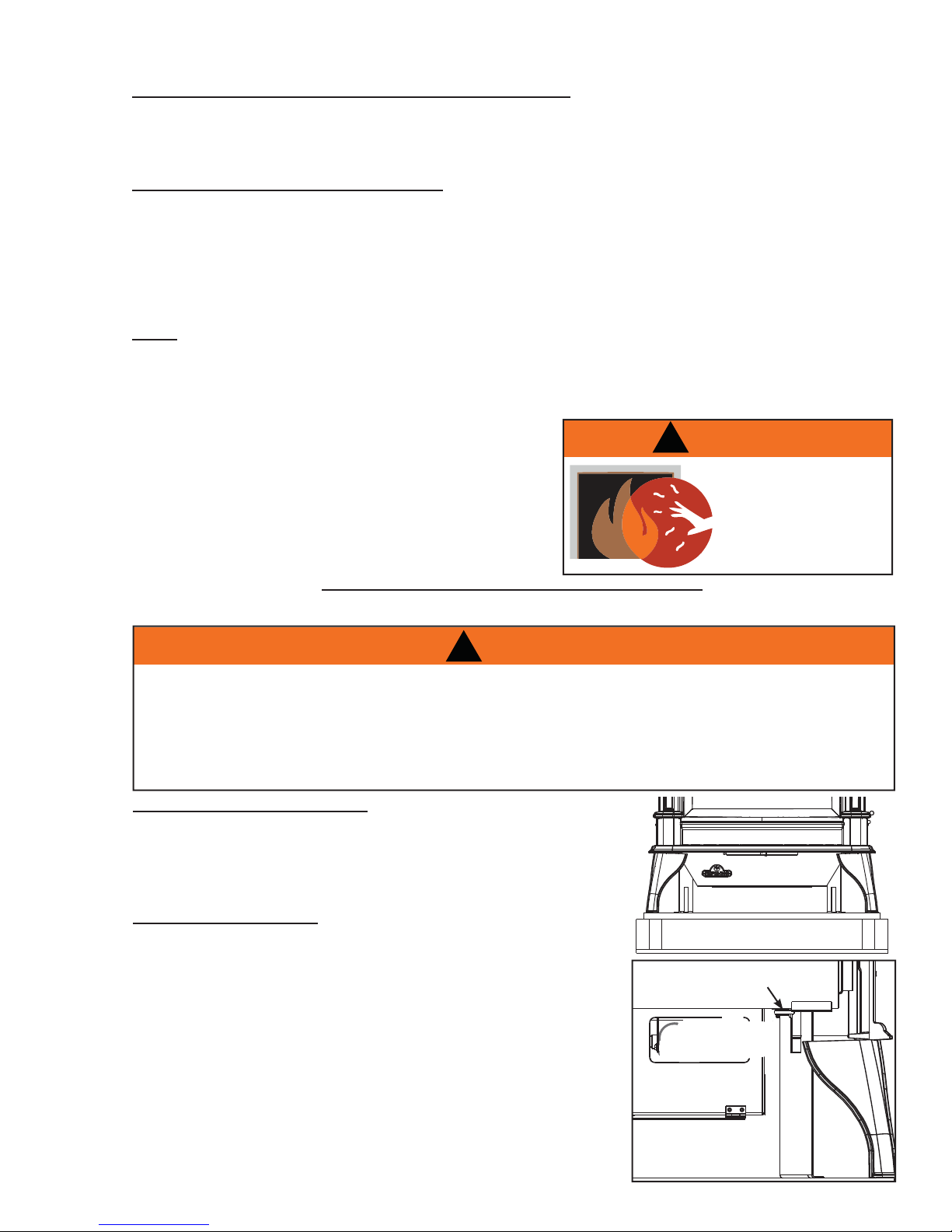
1.6 SHIPPING BRACKET
THE TOP CASTING IS NOT FASTENED TO THE STOVE ASSEMBLY. IT SIMPLY SITS ON THE STOVE
AS A LID. FOR SHIPPING PURPOSES IT IS HELD IN PLACE BY PLASTIC STRAPPING. ONCE THE
STRAPPING IS CUT, THE TOP SHOULD BE LIFTED OFF CAREFULLY AND STORED IN A SAFE PLACE
TO AVOID DAMAGE WHILE COMPLETING THE INSTALLATION OF THE STOVE. TO AVOID THE APPLI-
ANCE BEING DAMAGED DURING SHIPPING, A SHIPPING BRACKET HAS BEEN USED AND MUST BE
UNBOLTED BEFORE THE APPLIANCE CAN BE INSTALLED.
SHIPPING BRACKET REMOVAL
A. Remove the four screws holding the shipping bracket to the bot-
tom of the appliance.
B. Lift the appliance off the skid and set on a fl at surface.
C. Discard the screws, brackets and skid.
GLASS DOOR REMOVAL
A. Lift the top casting off.
B. Open the valve control cover. Pull the latch handles forward to
release. The door may now be safely removed by swinging the
bottom out and lifting it off.
!
WARNING
!
WARNING
HOT GLASS WILL
CAUSE BURNS.
DO NOT TOUCH GLASS
UNTIL COOLED.
NEVER ALLOW CHILDREN
TO TOUCH GLASS.
5.1
SHIPPING BRACKET
LATCH
W415-0788 / 05.15.09

8
NorthlineExpress.com
http://www.northlineexpress.com
Toll-Free 1-866-667-8454
2.0 VENTING - MODEL GDS60
!
WARNING
RISK OF FIRE, MAINTAIN SPECIFIED AIR SPACE CLEARANCES TO VENT PIPE AND APPLIANCE.
THE VENT SYSTEM MUST BE SUPPORTED EVERY 3 FEET FOR BOTH VERTICAL AND HORIZONTAL RUNS. USE
SUPPORTS OR EQUIVALENT NON-COMBUSTIBLE STRAPPING TO MAINTAIN THE REQUIRED CLEARANCE FROM
COMBUSTIBLES. SPACERS ARE ATTACHED TO THE INNER FLEX PIPE AT PREDETERMINED INTERVALS TO
MAINTAIN AN EVEN AIR GAP TO THE OUTER FLEX PIPE. THIS GAP IS REQUIRED FOR SAFE OPERATION. A
SPACER IS REQUIRED AT THE START, MIDDLE AND END OF EACH ELBOW TO ENSURE THIS GAP IS MAINTAINED.
THESE SPACERS MUST NOT BE REMOVED. USE WOLF STEEL LTD. SUPPORT RING ASSEMBLY W010-0370 OR
EQUIVALENT NON-COMBUSTIBLE STRAPPING TO MAINTAIN THE MINIMUM CLEARANCE TO COMBUSTIBLES
FOR BOTH VERTICAL AND HORIZONTAL RUNS.
THIS APPLIANCE USES A 4” EXHAUST / 7” AIR INTAKE VENT PIPE SYSTEM.
Refer to the section applicable to your installation.
For safe and proper operation of the appliance follow the venting instruction exactly. Deviation from the
minimum vertical vent length can create diffi culty in burner start-up and/or carboning. Under extreme vent
confi gurations, allow several minutes (5-15) for the fl ame to stabilize after ignition. Vent lengths that pass
through unheated spaces (attics, garages, crawl spaces) should be insulated with the insulation wrapped in
a protective sleeve to minimize condensation. Provide a means for visually checking the vent connection to
the appliance after the appliance is installed. Use a fi restop, vent pipe shield or attic insulation shield when
penetrating interior walls, fl oor or ceiling.
NOTE: If for any reason the vent air intake system is disassembled; reinstall per the instructions
provided for the initial installation.
7.1
A terminal shall not terminate directly above a sidewalk or paved driveway which is located between two single family dwellings and serves both dwellings. Local codes or regulations may require different clearances.
Do not allow the inside liner to bunch up on horizontal or vertical runs and elbows. Keep it pulled tight.
A 1-1/4" air gap all around between the inner liner and outer appliance pipe is required for safe operation. Use a fi restop when penetrating interior walls, fl
Use only Wolf Steel, Simpson Dura-Vent, Selkirk Direct Temp or American Metal Amerivent venting components. Minimum and maximum vent lengths, for both horizontal and vertical installations, and air terminal locations for either systems are set out in this manual and must be adhered to.
oor or ceiling.
W415-0788 / 05.15.09
2.1 VENTING LENGTHS AND AIR TERMINAL LOCATIONS
NorthlineExpress.com
http://www.northlineexpress.com
Toll-Free 1-866-667-8454
Use only Wolf Steel, Simpson Dura-V ent, Selkirk Direct Temp, American Metal Amerivent or Metal-Fab venting
components. Minimum and maximum vent lengths, for both horizontal and vertical installations, and air terminal
locations for either system are set out in this manual and must be adhered to. For Simpson Dura-Vent, Selkirk
Direct Temp, American Metal Amerivent and Metal-Fab follow the installation procedure provided with the venting
components.
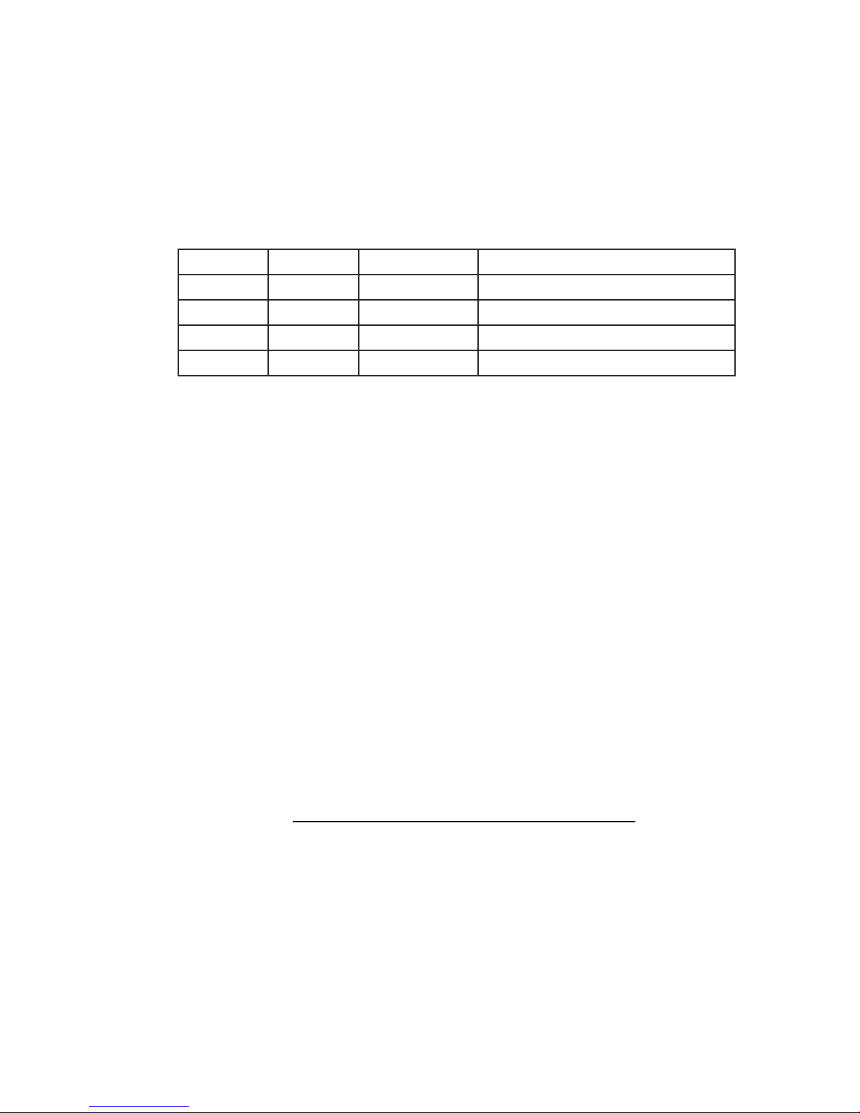
A starter adaptor must be used with the following vent systems and may be purchased from the corresponding
supplier:
PART 4”/7” SUPPLIER WEBSITE
Duravent W175-0053 Wolf Steel www.duravent.com
Amerivent 4DSC-N2 American Metal www.americanmetalproducts.com
Direct Temp 4DT-AAN Selkirk www.selkirkcorp.com
SuperSeal 4DNA Metal-Fab www.mtlfab.com
* For Simpson Dura-Vent, Selkirk Direct Temp, American Metal Amerivent and Metal-Fab follow the
installation procedure found on the website for your venting supplier.
For vent systems that provide seals on the inner exhaust fl ue, only the outer air intake joints must be sealed using a
red high temperature silicone (RTV). This same sealant may be used on both the inner exhaust and outer intake vent
pipe joints of all other approved vent systems except for the exhaust vent pipe connection to the appliance fl ue collar
which must be sealed using the black high temperature sealant Mill Pac.
9
When using Wolf Steel venting components, use only approved Wolf Steel termination kits: wall terminal kit GD175
(7/12’ of venting included), or 1/12 to 7/12 pitch roof terminal kit GD1 10, 8/12 to 12/12 roof terminal kit GD111, fl at
roof terminal kit GD112 or periscope kit GD180 (for wall penetration below grade) in conjunction with the appropriate
venting components.
For optimum fl ame appearance and appliance operation, keep the vent length and number of elbows to a
minimum. It is recommended that all horizontal runs have a minimum 1/4” rise per foot. The air terminal must
remain unobstructed at all times. Examine the air terminal at least once a year to verify that it is unobstructed
and undamaged. Rigid and fl exible venting systems must not be combined. Different venting manufacturers
components must not be combined.
These vent kits allow for either horizontal or vertical venting of the appliance. The maximum allowable horizontal run
is 20 feet. The maximum allowable vertical vent length is 40 feet. The maximum number of vent connections is two
horizontally or three vertically (excluding the appliance and the air terminal connections) when using fl exible venting.
Deviation from the minimum vertical vent length can create diffi culty in burner start-up and/or carboning.
Use an adjustable pipe as the fi nal length of rigid piping to the stove for ease of installation.
8.5
W415-0788 / 05.15.09
10
NorthlineExpress.com
http://www.northlineexpress.com
Toll-Free 1-866-667-8454
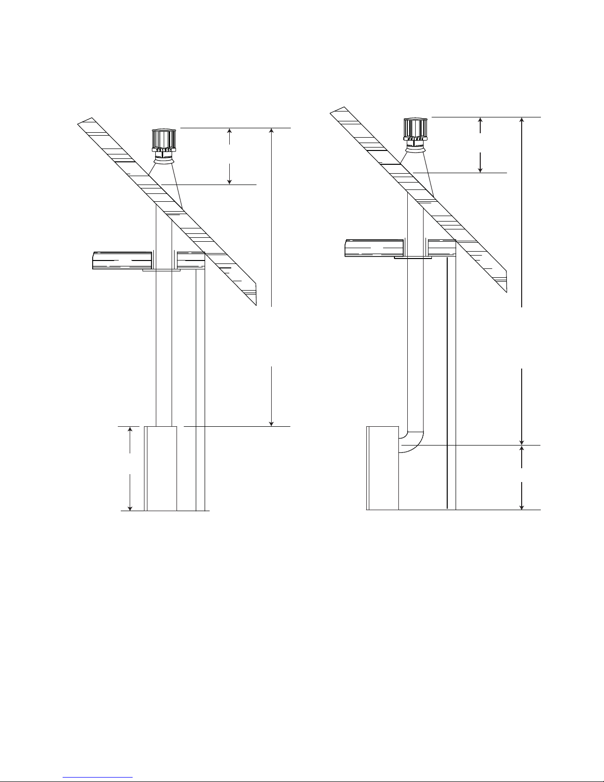
2.2 TYPICAL VENT INSTALLATIONS
16" MINIMUM
16" MINIMUM
30 1/2"
TOP VENT
40 FEET
MAXIMUM
34"
MINIMUM
40 FEET
MAXIMUM
34"
MINIMUM
24"
REAR VENT
W415-0788 / 05.15.09
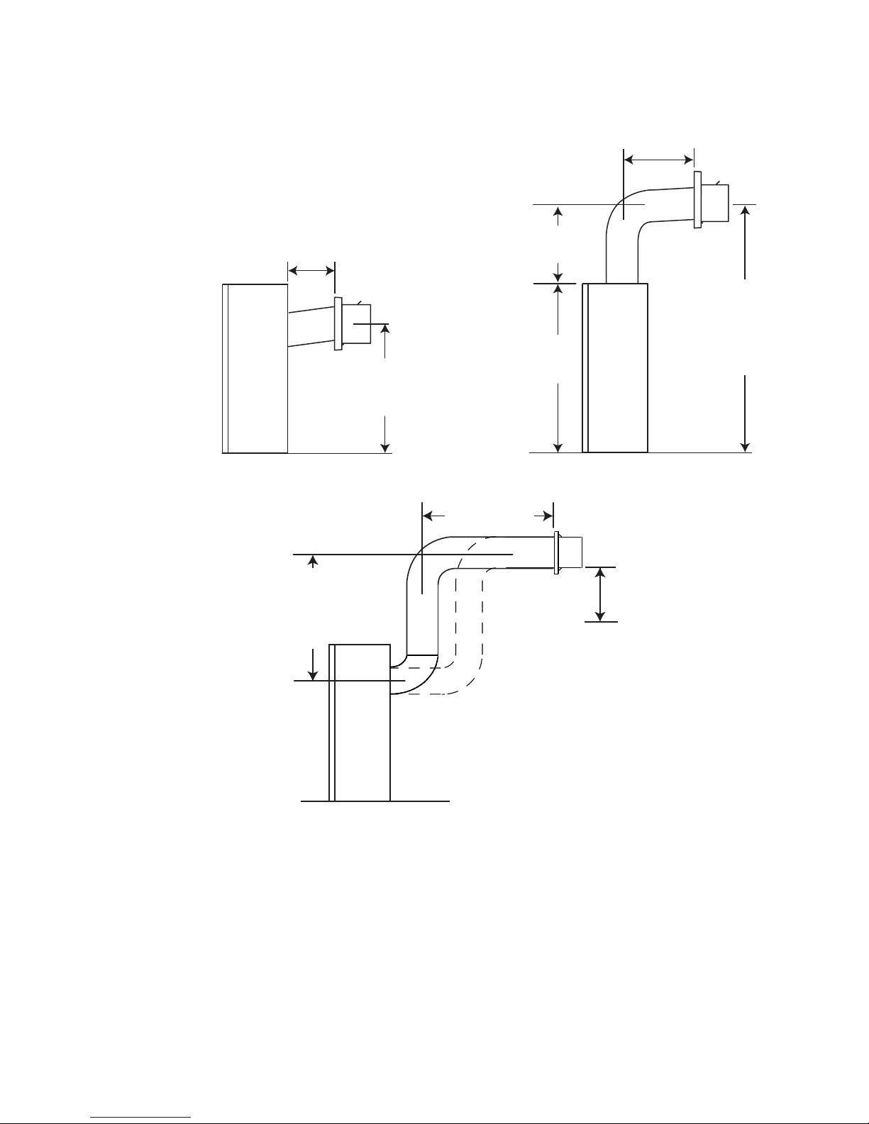
34" MAXIMUM
NorthlineExpress.com
http://www.northlineexpress.com
Toll-Free 1-866-667-8454
11
24" MAX
24"
MINIMUM
PLUS RISE*
24” MINIMUM
REGARDLESS OF
HORIZONTAL
VENT LENGTH
29" MINIMUM
20 FT MAX
30 1/2"
59 1/2"
MINIMUM
PLUS
RISE*
12” MINIMUM
TO GRADE
* See "VENTING" section.
MAX. HORIZONTAL
RUN
W415-0788 / 05.15.09
12
NorthlineExpress.com
http://www.northlineexpress.com
Toll-Free 1-866-667-8454
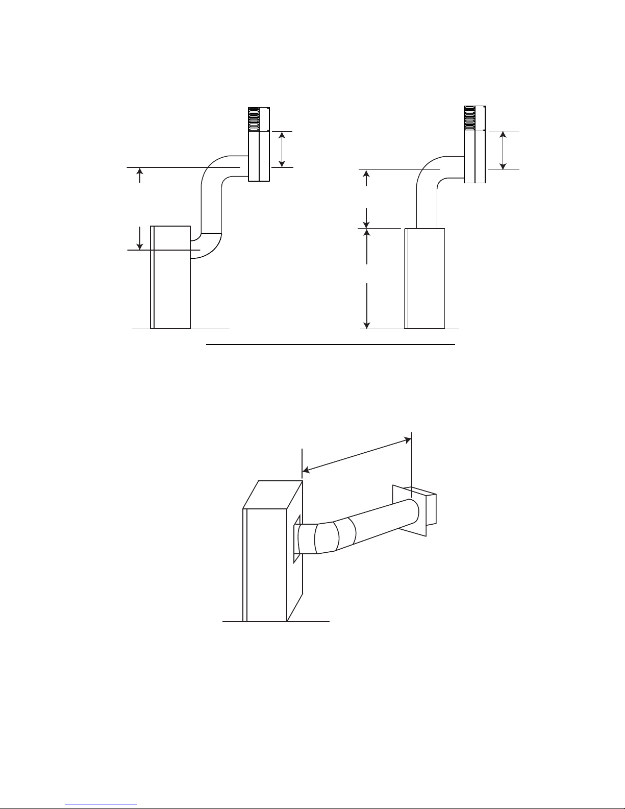
2.3 SPECIAL VENT INSTALLATIONS
Use the periscope kit to locate the air termination above grade. The periscope must be installed so that when
fi nal grading is completed, the bottom air slot is located a minimum 12” above grade. The maximum allowable
vent length is 10’.
12" MIN. TO
GRADE
24" MINIMUM
2.4 CORNER INSTALLATION REAR EXIT
The maximum vent length for a corner installation is 24".
12" MIN.
TO GRADE
29" MINIMUM
30 1/2"
9.4
24” MAXIMUM
CORNER INSTALLATION
0” RISE
W415-0788 / 05.15.09
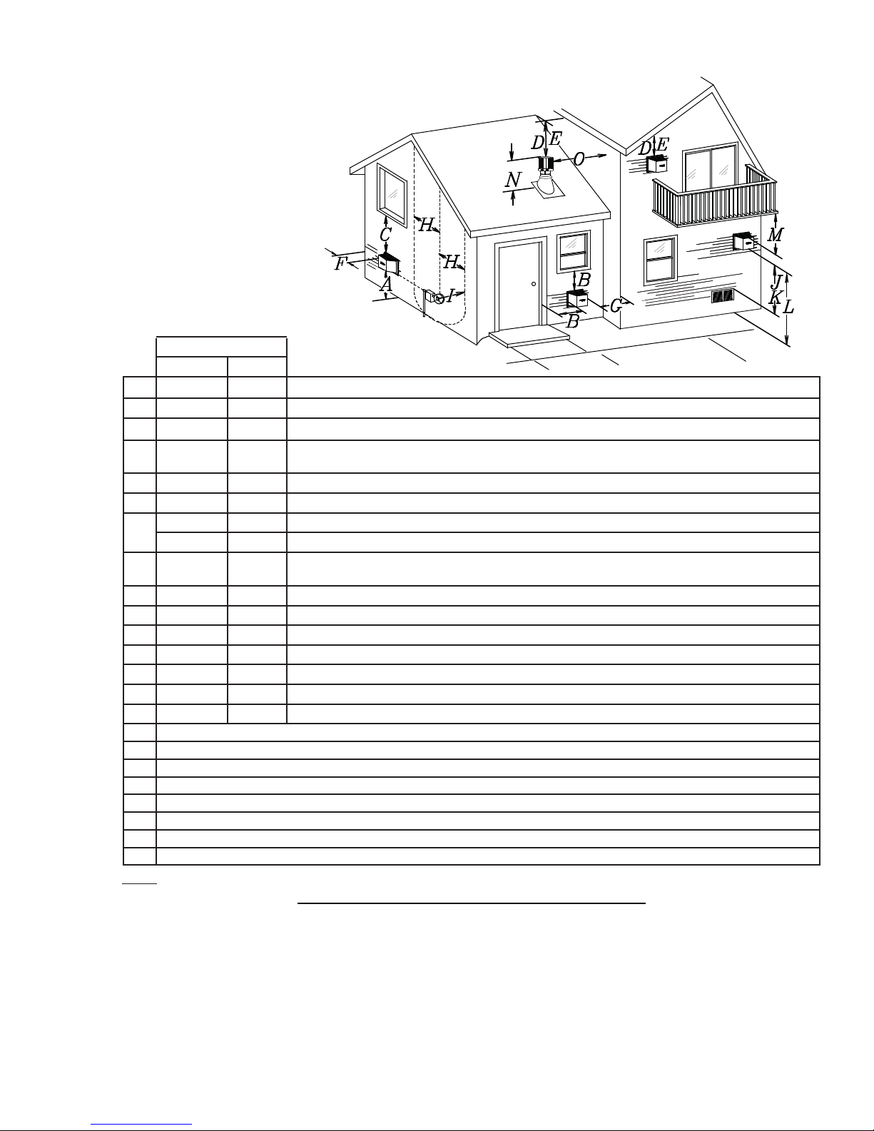
2.5 VENT TERMINAL CLEARANCES
NorthlineExpress.com
http://www.northlineexpress.com
Toll-Free 1-866-667-8454
INSTALLATIONS
CANADA U.S.A.
A 12” 12” Clearance above grade, veranda porch, deck or balcony.
B 12” 9” Clearance to windows or doors that open.
C 12” * 12” * Clearance to permanently closed windows.
D 18” ** 18” **
E 12” ** 12” ** Clearance to unventilated soffi t.
F 0” 0” Clearance to an outside corner wall.
G
0” *** 0” *** Clearance to an inside non-combustible corner wall or protruding non-combustible obstructions (chimney , etc.).
2” *** 2” *** Clearance to an inside combustible corner wall or protruding combustible obstructions (vent chase, etc.).
H 3’ 3’ ****
I 3’ 3’ **** Clearance to a service regulator vent outlet.
J 12” 9” Clearance to a non-mechanical air supply inlet to the building or a combustion air inlet to any other appliance.
K 6’ 3’ † Clearance to a mechanical air supply inlet.
L 7’ ‡ 7’ **** Clearance above a paved sidewalk or paved driveway located on public property.
M 12” †† 12” **** Clearance under a veranda, porch, deck or balcony.
N 16” 16” Clearance above the roof.
O 2’ †* 2’ †* Clearance from an adjacent wall including neighbouring buildings.
* Recommended to prevent condensation on windows and thermal breakage
** it is recommended to use a heat shield and to maximize the distance to vinyl clad soffi ts.
*** The periscope requires a minimum 18 inches clearance from an inside corner.
**** This is a recommended distance. For additional requirements check local codes.
† 3 feet above if within 10 feet horizontally.
‡ A vent shall not terminate directly above a sidewalk or paved driveway that is located between two single family dwellings and serves both dwellings.
†† Permitted only if the veranda, porch, or deck is fully open on a minimum of two sides beneath the fl oor.
†* Recommended to prevent recirculation of exhaust products. For additional requirements check local codes.
NOTE: Clearances are in accordance with local installation codes and the requirements of the gas supplier.
Vertical clearance to ventilated soffi ts located above the terminal within a horizontal distance of 2’ from
the centerline of the terminal.
Clearance to each side of the centerline extended above the meter / regulator assembly to a maximum
vertical distance of 15’.
13
12.1
W415-0788 / 05.15.09
14
NorthlineExpress.com
http://www.northlineexpress.com
Toll-Free 1-866-667-8454
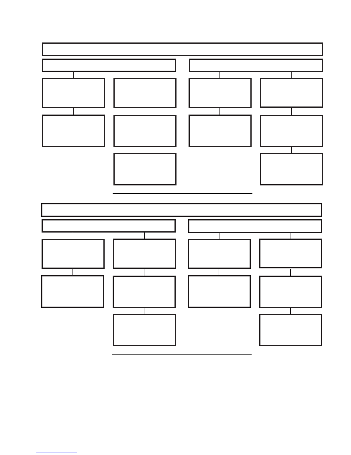
2.6 VENTING APPLICATION FLOW CHART
TOP EXIT
Horizontal Termination
Vertical rise is equal
to or greater than
the horizontal run
Horizontal run +
vertical rise to
maximum of 40 feet
Horizontal Termination
Vertical rise is less
than horizontal run
Horizontal run +
vertical rise to
maximum of 24.75
feet
4.2 times the
vertical rise equal to
or greater than the
horizontal run
REAR EXIT
Vertical Termination
Vertical rise is equal
to or greater than
the horizontal run
Horizontal run +
vertical rise to
maximum of 40 feet
Vertical Termination
Vertical rise is less
than horizontal run
Horizontal run +
vertical rise to
maximum of 40 feet
3 times the vertical
rise equal to or
greater than the
horizontal run
13.1
Vertical rise is equal
to or greater than
the horizontal run
Horizontal run +
vertical rise to
maximum of 40 feet
Vertical rise is less
than horizontal run
Horizontal run +
vertical rise to
maximum of 24.75
feet
3.5 times the
vertical rise equal to
or greater than the
horizontal run
Vertical rise is equal
to or greater than
the horizontal run
Horizontal run +
vertical rise to
maximum of 40 feet
Vertical rise is less
than horizontal run
Horizontal run +
vertical rise to
maximum of 40 feet
3 times the vertical
rise equal to or
greater than the
horizontal run
13.2
W415-0788 / 05.15.09

2.7 DEFINITIONS
NorthlineExpress.com
http://www.northlineexpress.com
Toll-Free 1-866-667-8454
For the following symbols used in the venting calculations and examples are:
> - greater than
> - equal to or greater than
< - less than
< - equal to or less than
- total of both horizontal vent lengths (Hr) and offsets (Ho) in feet
H
T
HR - combined horizontal vent lengths in feet
HO - offset factor: .03 (total degrees of offset - 90°*) in feet
VT - combined vertical vent lengths in feet
2.8 ELBOW VENT LENGTH VALUES
FEET INCHES
1° 0.03 0.5
15° 0.45 6.0
30° 0.9 11.0
45° 1.35 16.0
90°* 2.7 32.0
* The fi rst 90° offset has a zero value and is shown in the formula as - 90°
15
14.1
15.1
W415-0788 / 05.15.09
 Loading...