

Napoleon GDS25N-1, GDS25P-1 Installation And Operating Instructions Manual

INSTALLER: LEAVE THIS MANUAL WITH THE APPLIANCE.
NEVER LEAVE CHILDREN OR OTHER AT RISK INDIVIDUALS ALONE WITH THE APPLIANCE
DANGER
the hot viewing glass is provided with this appliance
HOT GLASS WILL CAUSE
BURNS.
DO NOT TOUCH GLASS UNTIL
COOLED.
NEVER ALLOW CHILDREN TO
TOUCH GLASS.
!
WARNING
ADD SAFETY STANDARD INFORMATION...
ADD
PRODUCT
IMAGE
CONSUMER: RETAIN THIS MANUAL FOR FUTURE REFERENCE.
INSTALLATION AND
EN
OPERATING INSTRUCTIONS
CERTIFIED TO CANADIAN AND AMERICAN NATIONAL STANDARDS: CSA 2.22 AND ANSI z21.50 FOR VENTED GAS FIREPLACES
SAFETY INFORMATION
!
WARNING
If the information in these instructions
are not followed exactly, a fi re or
explosion may result causing property
damage, personal injury or loss of life.
- Do not store or use gasoline or other fl ammable
vapors and liquids in the vicinity of this or any
other appliance.
- WHAT TO DO IF YOU SMELL GAS:
• Do not try to light any appliance.
• Do not touch any electrical switch; do not use
any phone in your building.
• Immediately call your gas supplier from a
neighbour’s phone. Follow the gas supplier’s
instructions.
• If you cannot reach your gas supplier, call the
fi re department.
- Installation and service must be performed by a
qualifi ed installer, service agency or the supplier.
FR
PG
51
GDS25N-1
NATURAL GAS
GDS25P-1
PROPANE
SAFETY BARRIER
FOR INDOOR USE ONLY!
!
This appliance may be installed in an aftermarket,
permanently located, manufactured home (USA
only) or mobile home, where not prohibited by
local codes.
This appliance is only for use with the type of gas
indicated on the rating plate. This appliance is
not convertible for use with other gases, unless a
certifi ed kit is used.
Wolf Steel Ltd., 24 Napoleon Rd., Barrie, ON, L4M 0G8 Canada /
$10.00
Phone 1 (866) 820-8686 • www.napoleonfi replaces.com • hearth@napoleonproducts.com
103 Miller Drive, Crittenden, Kentucky, USA, 41030
HOT GLASS WILL CAUSE
BURNS.
DO NOT TOUCH GLASS UNTIL
COOLED.
NEVER ALLOW CHILDREN TO
TOUCH GLASS.
A barrier designed to reduce the risk of burns from
and shall be installed for the protection of children
and other at-risk individuals.
ADD ETL,
OMNI or CSA
LOGO HERE
1.1A
W415-2207 / A / 08.28.17

2
EN
TABLE OF CONTENTS
NOTE: The camera icon indicates video tutorials are available as additional reference, visit
http://www.napoleonfireplaces.com/category/product-support/support-centre/
1.0 INSTALLATION OVERVIEW 3
2.0 INTRODUCTION 4
3.0 VENTING 8
4.0 INSTALLATION 18
5.0 FINISHING 26
6.0 OPTIONAL BLOWER INSTALLATION 29
7.0 WIRING DIAGRAM 31
8.0 OPERATION 32
9.0 ADJUSTMENT 37
10.0 MAINTENANCE 39
11.0 REPLACEMENT PARTS 42
12.0 ACCESSORIES 45
13.0 TROUBLESHOOTING 46
14.0 WARRANTY 48
15.0 SERVICE HISTORY 49
2.2 GENERAL INSTRUCTIONS 5
2.1 DIMENSIONS 5
2.3 GENERAL INFORMATION 6
2.4 RATING PLATE INFORMATION 7
3.1 SPECIAL VENT INSTALLATIONS 10
3.1.1 PERISCOPE TERMINATION 10
3.1.2 CORNER TERMINATION 10
3.2 VENT TERMINAL CLEARANCES 11
3.3 DEFINITIONS 12
3.4 ELBOW VENT LENGTH VALUES 12
3.5 HORIZONTAL TERMINATION 13
3.6 VERTICAL TERMINATION 15
3.7 VERTICAL THROUGH EXISTING CHIMNEY 17
4.1 HORIZONTAL INSTALLATION 19
4.2 VERTICAL INSTALLATION 19
4.3 HORIZONTAL AIR TERMINAL INSTALLATION 20
4.4 EXTENDED HORIZONTAL AND CORNER AIR TERMINAL INSTALLATION 20
4.5 VERTICAL AIR TERMINAL INSTALLATION 21
4.6 APPLIANCE VENT CONNECTION 22
4.7 GAS INSTALLATION 22
4.8 MOBILE HOME 23
4.9 MINIMUM CLEARANCE TO COMBUSTIBLES 24
4.10 MINIMUM MANTEL OR SHELF CLEARANCES 25
5.1 CAST FRONT INSTALLATION AND REMOVAL 26
5.2 SAFETY BARRIER INSTALLATION AND REMOVAL 26
5.3 GLASS DOOR INSTALLATION AND REMOVAL 27
5.4 LOG PLACEMENT 27
5.5 LOGO PLACEMENT 28
8.1 GENERAL TRANSMITTER LAYOUT 33
8.2 INITIALIZING THE TRANSMITTER/BATTERY HOLDER FOR THE FIRST TIME 33
8.3 TEMPERATURE DISPLAY 34
8.4 FLAME HEIGHT 34
8.5 BLOWER SPEED 34
8.6 NIGHT LIGHT DIMMER CONTROL 34
8.7 CONTINUOUS PILOT / INTERMITTENT PILOT (CPI / IPI) SELECTION 35
8.8 KEY LOCK 35
8.9 LOW BATTERY 35
8.10 LOW BATTERY / MANUAL BYPASS 36
9.1 RESTRICTING VERTICAL VENTS 37
9.2 VENTURI ADJUSTMENT 37
9.3 PILOT BURNER ADJUSTMENT 37
9.4 FLAME CHARACTERISTICS 38
10.1 ANNUAL MAINTENANCE 40
10.2 NIGHT LIGHT REPLACEMENT 41
10.3 PILOT INJECTOR AND ORIFICE REPLACEMENT 41
10.4 CARE OF GLASS 42
10.5 CARE OF PLATED PARTS 42
11.1 OVERVIEW 43
11.2 VALVE TRAIN ASSEMBLY 44
NOTE: Changes, other than editorial, are denoted by a vertical line in the margin.
W415-2207 / A / 08.28.17
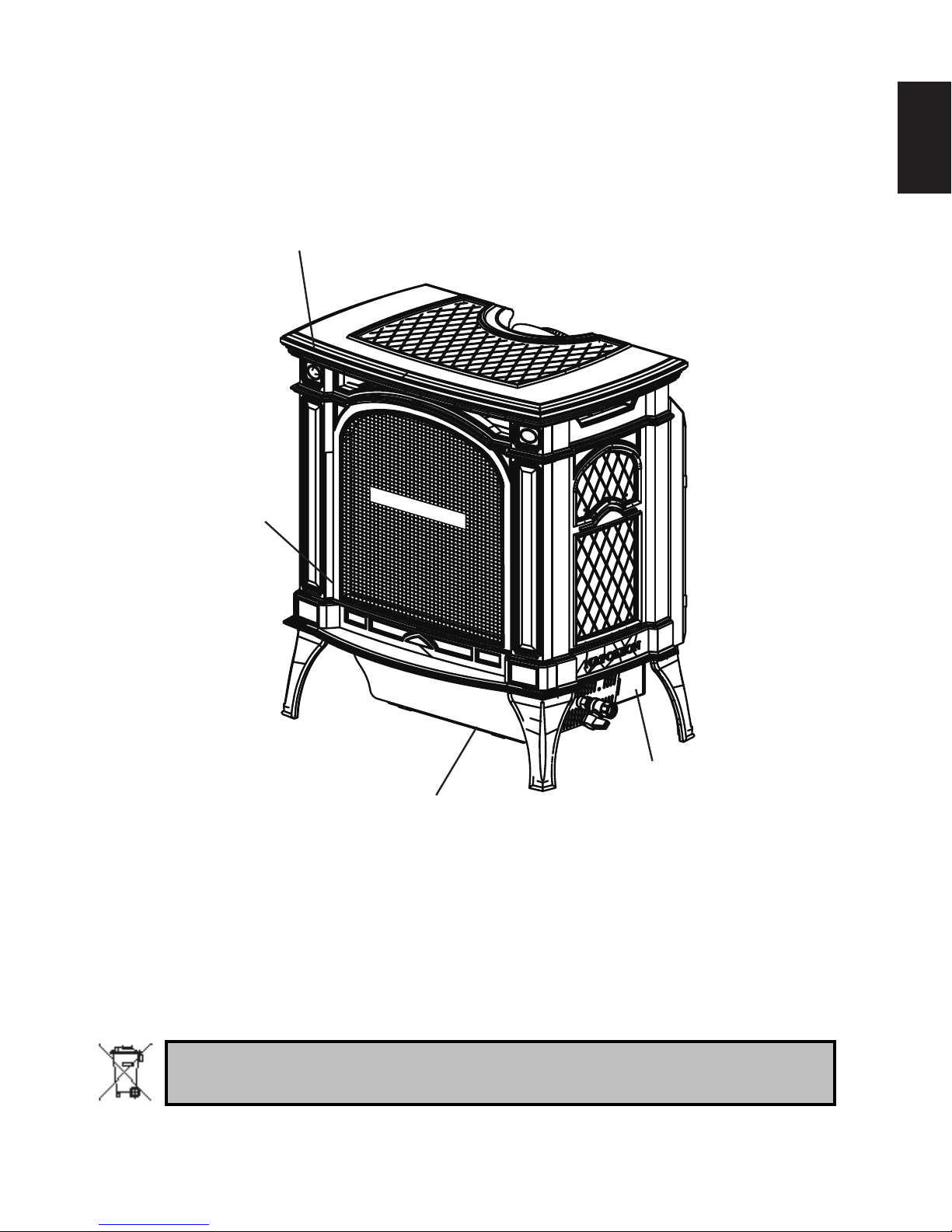
1.0 INSTALLATION OVERVIEW
Cast, see “CAST FRONT
INSTALLATION AND
REMOVAL” section.
Door, see “GLASS
DOOR INSTALLATION
AND REMOVAL”
section.
SAFETY BARRIER
3
EN
Rating plate, see “RATING
PLATE INFORMATION”
section.
Batteries must be disposed of according to the local laws and regulations. Some batteries may be
recycled, and may be accepted for disposal at your local recycling center. Check with your
municipality for recycling instructions.
Blower, see
“OPTIONAL BLOWER
INSTALLATION”
section.
W415-2207 / A / 08.28.17
!
WARNING
3.1A
• THIS APPLIANCE IS HOT WHEN OPERATED AND CAN CAUSE SEVERE BURNS IF CONTACTED.
• ANY CHANGES OR ALTERATIONS TO THIS APPLIANCE OR IT’S CONTROLS CAN BE DANGEROUS AND IS PROHIBITED.
• Do not operate appliance before reading and understanding operating instructions. Failure to operate appliance according to operating
instructions could cause fi re or injury.
• Ensure the glass door is opened or removed when lighting the pilot for the fi rst time and when the gas supply has run out.
• Risk of fi re or asphyxiation do not operate appliance with fi xed glass removed and never obstruct the front opening of the appliance.
• Objects placed in front of the appliance must be kept a minimum of 4 feet (1.22m) from the front face of the appliance.
• Do not connect 110 volts to the control valve, with the exception of models; GSST8 and GT8.
• Risk of burns. The appliance should be turned off and cooled before servicing.
• Do not install damaged, incomplete or substitute components.
• Risk of cuts and abrasions. Wear protective gloves, protective footwear, and safety glasses during installation. Sheet metal edges may be
sharp.
• Do not burn wood or other materials in this appliance.
• Provide adequate ventilation and combustion air. Provide adequate accessibility clearance for servicing and operating the appliance.
Never obstruct the front opening of the appliance.
• The appliance area must be kept clear and free from combustible materials, gasoline and other fl ammable vapors and liquids.
• High pressure will damage valve. Disconnect gas supply piping before pressure testing gas line at test pressures above 1/2 psig. Close
the manual shut-off valve before pressure testing gas line at test pressures equal to or less than 1/2 psig (35mb).
• The appliance must not be operated at temperatures below freezing (32°F / 0°C). Allow the appliance to warm to above freezing prior to
operation, with the exception of models; GSS36, GSS42; these appliances are suitable for 0°F / -18°C.
• Children and adults should be alerted to hazards of high surface temperature and should stay away to avoid burns or clothing ignition.
• Young children should be carefully supervised when they are in the same room as the appliance. Toddlers, young children and
others may be susceptible to accidental contact burns. A physical barrier is recommended if there are at risk individuals in the
house. To restrict access to an appliance or stove, install an adjustable safety gate to keep toddlers, young children and other at
risk individuals out of the room and away from hot surfaces.
• Clothing or other fl ammable material should not be placed on or near the appliance.
• Due to high temperatures, the appliance should be located out of traffi c and away from furniture and draperies.
• Furniture or other objects must be kept a minimum of 4 feet (1.22m) away from the front of the appliance.
• Ensure you have incorporated adequate safety measure to protect infants/toddlers from touching hot surfaces.
• Even after the appliance is off, it will remain hot for an extended period of time.
• Check with your local hearth specialty dealer for safety screens and hearth guards to protect children from hot surfaces. These screens
and guards must be fastened to the fl oor.
• Any safety screen, guard or barrier removed for servicing the appliance, must be replaced prior to operating the appliance.
• It is imperative that the control compartments, burners and circulating blower and its passageway in the appliance and venting system
are kept clean. The appliance and its venting system should be inspected before use and at least annually by a qualifi ed service person.
More frequent cleaning may be required due to excessive lint from carpeting, bedding material, etc. The appliance area must be kept
clear and free from combustible materials, gasoline and other fl ammable vapors and liquids.
• If the appliance shuts off, do not re-light until you provide fresh air. If appliance keeps shutting off, have it serviced. Keep burner and
control compartment clean.
• Under no circumstances should this appliance be modifi ed.
• Do not allow wind or fans to blow directly into the appliance. Avoid any drafts that alter burner fl ame patterns.
• Do not use a blower insert, heat exchanger insert or other accessory not approved for use with this appliance.
• This appliance must not be connected to a chimney fl ue pipe serving a separate solid fuel burning appliance.
• Do not use this appliance if any part has been under water. Immediately call a qualifi ed service technician to inspect the appliance and to
replace any part of the control system and any gas control which has been under water.
• Do not operate the appliance with the glass door removed, cracked or broken. Replacement of the glass should be done by a licensed or
qualifi ed service person, if equipped.
• Do not strike or slam shut the appliance glass door, if equipped.
• Only doors / optional fronts certifi ed with the appliance are to be installed on the appliance.
• Keep the packaging material out of reach of children and dispose of the material in a safe manner. As with all plastic bags, these are not
toys and should be kept away from children and infants.
• Carbon or soot should not occur in a vent free appliance as it can distribute into the living area of your home. If you notice any signs of
carbon or soot, immediately turn off your appliance and arrange to have it serviced by a qualifi ed technician before operating it again.
• If equipped, the screen must be in place (closed) when the appliance is in operation.
• When equipped with pressure relief doors, they must be kept closed while the appliance is operating to prevent exhaust fumes
containing carbon monoxide, from entering into the home. Temperatures of the exhaust escaping through these openings can also cause
the surrounding combustible materials to overheat and catch fi re.
• Carbon monoxide poisoning may lead to death; early signs of carbon monoxide poisoning resemble the fl u, with headache, dizziness
and/or nausea. If you have these signs, the heater may not be working properly. Get fresh air at once! Have heater serviced. Some
people; pregnant women, persons with heart or lung disease, anemia, those under the infl uence of alcohol, those at high altitudes are
more affected by carbon monoxide than others. Failure to keep the primary air opening(s) of the burner(s) clean may result in sooting and
property damage.
• As with any combustion appliance, we recommend having your appliance regularly inspected and serviced as well as having a Carbon
Monoxide Detector installed in the same area to defend you and your family against Carbon Monoxide.(Not applicable for outdoor
appliances).
• Ensure clearances to combustibles are maintained when building a mantel or shelves above the appliance. Elevated temperatures on the
wall or in the air above the appliance can cause melting, discolouration or damage to decorations, a T.V. or other electronic components.
• For appliances equipped with a safety barrier; the barrier is designed to reduce the risk of burns from the hot viewing glass
is provided with this appliance and shall be installed. If the barrier becomes damaged, the barrier shall be replaced with the
manufacturer’s barrier for this appliance.
• Installation and repair should be done by a qualifi ed service person. The appliance should be inspected before use and at least
annually by a professional service person. More frequent cleaning may be required due to excessive lint from carpeting, bedding
material, etc. It is imperative that control compartments, burners and circulating air passageways of the appliance be kept clean.
• For outdoor products only: this appliance must not be installed indoors or within any structure that prevents or inhibits the exhaust gases
from dissipating in the outside atmosphere.
• If applicable, the millivolt version of this appliance uses and requires a fast acting thermocouple. Replace only with a fast acting
thermocouple supplied by Wolf Steel Ltd.
4
2.0 INTRODUCTION
EN
W415-2207 / A / 08.28.17
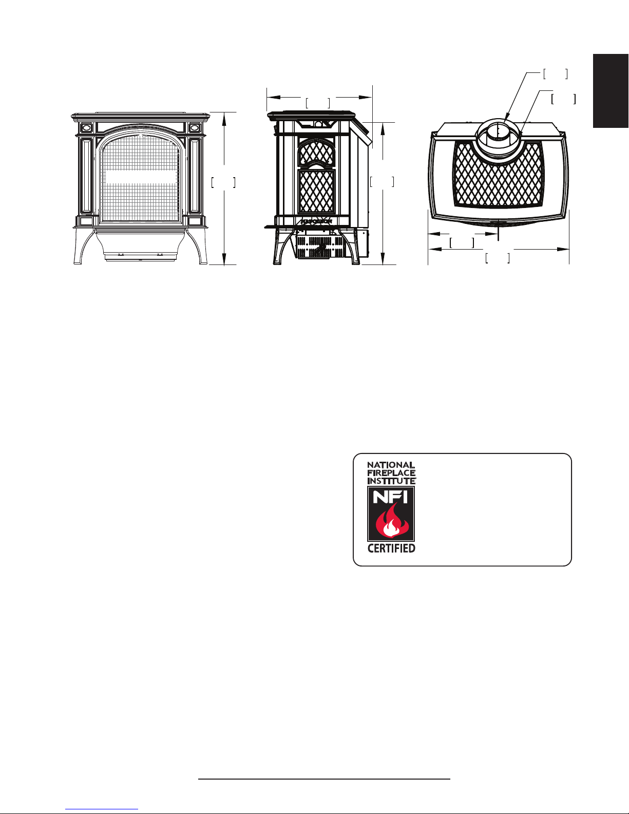
2.1 DIMENSIONS
25 5/8"
651mm
23 5/8"
600mm
17 1/2"
445mm
23 1/2"
597mm
12 3/4"
324mm
Ø
4"
102mm
Ø
7"
178mm
SAFETY BARRIER
the most desirable and benefi cial location for an appliance is in the center of a building, thereby allowing the
most effi cient use of the heat created. The location of windows, doors and the traffi c fl ow in the room where
2.2 GENERAL INSTRUCTIONS
THIS GAS APPLIANCE SHOULD BE INSTALLED AND SERVICED BY A QUALIFIED INSTALLER to
conform with local codes. Installation practices vary from region to region and it is important to know the
specifi cs that apply to your area, for example in Massachusetts State:
• This product must be installed by a licensed plumber or gas fi tter when installed within the
commonwealth of Massachusetts.
• The appliance damper must be removed or welded in the open position prior to installation of an
appliance insert or gas log.
• The appliance off valve must be a “T” handle gas cock.
• The fl exible connector must not be longer than 36 inches (0.9m).
• A Carbon Monoxide detector is required in all rooms containing gas fi red appliances.
• The appliance is not approved for installation in a bedroom or bathroom unless the unit is a direct vent
sealed combustion product.
The installation must conform with local codes or, in
absence of local codes, the National Gas and Propane
Installation Code CSA B149.1 in Canada, or the National
Fuel Gas Code, ANSI Z223.1 / NFPA 54 in the United
States. Suitable for mobile home installation if installed in
accordance with the current standard CAN/CSA Z240MH
Series, for gas equipped mobile homes, in Canada or ANSI
Z223.1 and NFPA 54 in the United States.
The appliance and its individual shutoff valve must be disconnected from the gas supply piping system
during any pressure testing of that system at test pressures in excess of 1/2 psig (35 mb). The appliance
must be isolated from the gas supply piping system by closing its individual manual shutoff valve during
any pressure testing of the gas supply piping system at test pressures equal to or less than 1/2 psig (35
mb). When installed with a blower or fan, the junction box must be electrically connected and grounded in
accordance with local codes. In the absence of local codes, use the current CSA C22.1 Canadian Electrical
Code in Canada or the ANSI / NFPA 70 National Electric Code in the United States. In the case where
the blower is equipped with a power cord it must be connected into a properly grounded receptacle. The
grounding prong must not be removed from the cord plug.
The following does not apply to inserts; as long as the required clearance to combustibles is maintained,
www.ncertied.org
We suggest that our gas
hearth products be installed
and serviced by professionals
who are certied in the U.S.
by the National Fireplace
®
Institute
(NFI) as NFI Gas
Specialists
5
EN
the appliance is to be located should be considered. If possible, you should choose a location where the
vent will pass through the house without cutting a fl oor or roof joist. If the appliance is installed directly on
carpeting, vinyl tile or other combustible material other than wood fl ooring, the appliance shall be installed
on a metal or wood panel extending the full width and depth, unless otherwise tested.
4.1
W415-2207 / A / 08.28.17
EN
6
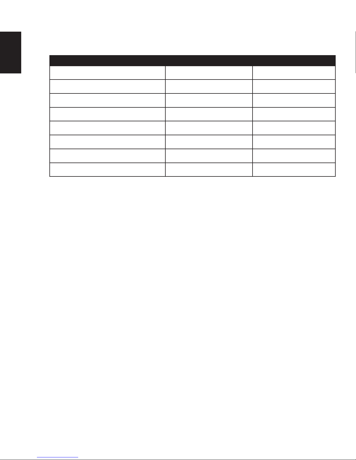
2.3 GENERAL INFORMATION
FOR YOUR SATISFACTION, THIS APPLIANCE HAS BEEN TEST-FIRED TO ASSURE ITS OPERATION
AND QUALITY!
GDS25-1
NG P
Altitude (FT) 0-4,500 0-4,500
Max. Input (BTU/HR) 24,500 23,000
Max. Output (BTU/HR) 19,600 18,400
Efciency (w/the fan on) 80% 80%
Min. Inlet Gas Supply Pressure 4.5" Water Column (11mb) 11" Water Column (27mb)
Max. Inlet Gas Supply Pressure 13" Water Column (17mb) 13" Water Column (32mb)
Manifold Pressure (Under Flow Conditions) 3.5" Water Column (9mb) 10" Water Column (25mb)
When the appliance is installed at elevations above 4,500ft (1372m), and in the absence of specific recommendations
from the local authority having jurisdiction, the certified high altitude input rating shall be reduced at the rate of 4% for
each additional 1,000ft (305m).
Expansion / contraction noises during heating up and cooling down cycles are normal and to be expected.
This appliance is only for use with the type of gas indicated on the rating plate. This appliance is not
convertible for use with other gases, unless a certified kit is used.
The blower power cord must be connected into a properly grounded receptacle. The grounding prong must
not be removed from the cord plug.
This appliance is approved for closet or recessed installations, as well as for bathroom, bedroom and
bed-sitting room installations and is suitable for mobile home installations. The natural gas model can be
installed in a mobile home that is permanently positioned on its site and fueled with natural gas.
W415-2207 / A / 08.28.17
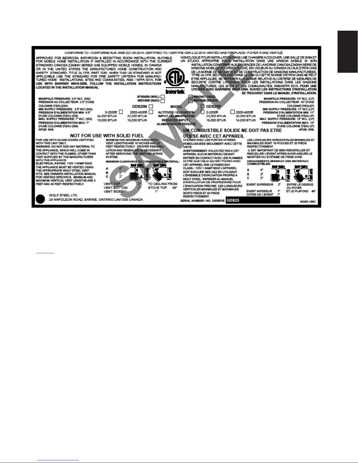
2.4 RATING PLATE INFORMATION
SAMPLE
7
EN
For rating plate location, see “INSTALLATION OVERVIEW” section.
This illustration is for referece only. Refer to the rating plate on the appliance for accurate information.
NOTE: The rating plate must remain with the appliance at all times. It must not be removed.
A barrier designed to reduce the risk of burns from the hot viewing glass is provided with the appliance
and shall be installed.
W415-2207 / A / 08.28.17

pass through unheated spaces (attics, garages, crawl spaces) be insulated with the insulation wrapped in a protective sleeve
(for wall penetration below grade). With fl exible
These vent kits allow for either horizontal or vertical venting of the appliance. The maximum allowable horizontal run is 20
!
WARNING
THE INNER PIPE AT PREDETERMINED INTERVALS TO MAINTAIN AN EVEN AIR GAP TO THE OUTER PIPE. THIS GAP
8
3.0 VENTING
EN
BOTH VERTICAL AND HORIZONTAL RUNS. USE SUPPORTS OR EQUIVALENT NON-COMBUSTIBLE STRAPPING
CLEARANCE TO COMBUSTIBLES FOR BOTH VERTICAL AND HORIZONTAL RUNS. SPACERS ARE ATTACHED TO
IS REQUIRED FOR SAFE OPERATION. A SPACER IS REQUIRED AT THE START, MIDDLE AND END OF EACH ELBOW
For safe and proper operation of the appliance, follow the venting instruction exactly. Deviation from the minimum vertical
vent length can create diffi culty in burner start-up and/or carboning. Under extreme vent confi gurations, allow several
minutes (5-15) for the fl ame to stabilize after ignition. Although not a requirement, it is recommended for vent lengths that
to minimize condensation. Provide a means for visually checking the vent connection to the appliance after the appliance is
installed. Use a fi restop, vent pipe shield or attic insulation shield when penetrating interior walls, fl oor or ceiling.
The vent terminal may be painted with a high temperature paint to match exterior colours. Use an outdoor paint suitable
for 400°F (200°C). Application and performance of paint is the consumer’s responsibility. Spot testing is recommended.
NOTE: If for any reason the vent air intake system is disassembled; reinstall per the instructions provided for the
initial installation.
NOTE: This appliance must be installed with a continuous connection of exhaust and air intake vent pipes.
Utilizing alternate constructions such as a chimney as part of the vent system is not permitted.
Use only Wolf Steel, Simpson Dura-Vent, Selkirk Direct Temp, American Metal Amerivent or Metal-Fab venting
components. Minimum and maximum vent lengths, for both horizontal and vertical installations, clearances from vent
pipes to combustibles and air terminal locations as set out in this manual apply to all vent systems and must be adhered
to. For Simpson Dura-Vent, Selkirk Direct Temp, American Metal Amerivent and Metal-Fab, follow the installation
procedure provided with the venting components or on the website for your venting supplier.
A starter adaptor must be used with the following vent systems and may be purchased from the corresponding supplier:
RISK OF FIRE, MAINTAIN SPECIFIED AIR SPACE CLEARANCES TO VENT PIPE AND APPLIANCE.
IF VENTING IS INCLUDED WITH SPACERS THE VENT SYSTEM MUST BE SUPPORTED EVERY 3FT (0.9m) FOR
TO MAINTAIN THE REQUIRED CLEARANCE FROM COMBUSTIBLES. USE WOLF STEEL LTD. SUPPORT RING
ASSEMBLY W010-0370 OR EQUIVALENT NON-COMBUSTIBLE STRAPPING TO MAINTAIN THE MINIMUM
TO ENSURE THIS GAP IS MAINTAINED. THESE SPACERS MUST NOT BE REMOVED.
THIS APPLIANCE USES A 4” (102mm) EXHAUST / 7” (178mm) AIR INTAKE VENT PIPE SYSTEM.
Refer to the section applicable to your installation.
VENT
MANUFACTURER
Duravent W175-0053 Wolf Steel www.duravent.com
Amerivent 4DSC-N2 American Metal www.americanmetalproducts.com
Direct Temp 4DT-AAN Selkirk www.selkirkcorp.com
SuperSeal 4DNA Metal-Fab www.mtlfab.com
For vent systems that provide seals on the inner exhaust fl ue, only the outer air intake joints must be sealed using a red
high temperature silicone (RTV). This same sealant may be used on both the inner exhaust and outer intake vent pipe
joints of all other approved vent systems except for the exhaust vent pipe connection to the appliance fl ue collar which
must be sealed using the black high temperature sealant Mill Pac. High temperature sealant must be ordered separately.
When using Wolf Steel venting components, use only approved Wolf Steel rigid / fl exible components with the following
termination kits: wall terminal kit GD-222, GD-222R, or 1/12 to 7/12 pitch roof terminal kit GD-110, 8/12 to 12/12 roof
terminal kit GD-111, fl at roof terminal kit GD-112 or periscope kit GD-201
venting, in conjunction with the various terminations, use either the 5 foot (1.5m) vent kit GD-220 or the 10 foot (3.1m)
vent kit GD-330. For stoves only: wall terminal kit GD175 (venting included).
For optimum fl ame appearance and appliance performance, keep the vent length and number of elbows to a minimum.
The air terminal must remain unobstructed at all times. Examine the air terminal at least once a year to verify that
it is unobstructed and undamaged.
Rigid and fl exible venting systems must not be combined. Different venting manufacturer components must not
be combined.
feet (6.1m). The maximum allowable vertical vent length is 40 feet (12.2m). The maximum number of vent connections is
W415-2207 / A / 08.28.17
two horizontally or three vertically (excluding the appliance and the air terminal connections) when using fl exible venting.
A terminal shall not terminate directly above a sidewalk or paved driveway which is located between two single family dwellings
and serves both dwellings. Local codes or regulations may require different clearances.
For stoves only: deviation from the minimum vertical vent length can create diffi culty in burner start-up and/or
carboning. Use an adjustable pipe as the fi nal length of rigid piping to the stove for ease of installation.
STARTER ADAPTER
PART NUMER
SUPPLIER WEBSITE
7.1

24” (61cm) MIN.
REGARDLESS OF
HORIZONTAL VENT
LENGTH
9
EN
16” (40.6cm)
25 5/8”
(65.1cm)
40FT (12m)
MAX
3FT (1m)
MIN
24” (61cm)
MAXIMUM
25 5/8”
(65.1cm)
The maximum horizontal run with a 57” (1.45m) vertical rise immediately above the appliance is 20 feet
(6.1m).
W415-2207 / A / 08.28.17

10
3.1 SPECIAL VENT INSTALLATIONS
3.1.1 PERISCOPE TERMINATION
EN
Use the periscope kit to locate the air termination above grade. The periscope must
be installed so that when nal grading is completed, the bottom air slot is located a
minimum of 12” (305mm) above grade. The maximum allowable vent length is
10’ (3.1m) for a replace and 8’ (2.4m) for a stove.
BELOW GRADE INSTALLATION
MAXIMUM 8FT (2.4M) VENT LENGTH
USE GD201 PERISCOPE KIT
HORIZONTAL RUN NOT TO EXCEED
VERTICAL RISE
12”
(305mm) MIN
TO GRADE
24” (610mm) MIN.
REGARDLESS OF OF
HORIZONTAL VENT
LENGTH
25 5/8”
(651mm)
3.1.2 CORNER TERMINATION
8.2
24” (610mm)
MAX.
SAFETY
SCREEN
W415-2207 / A / 08.28.17
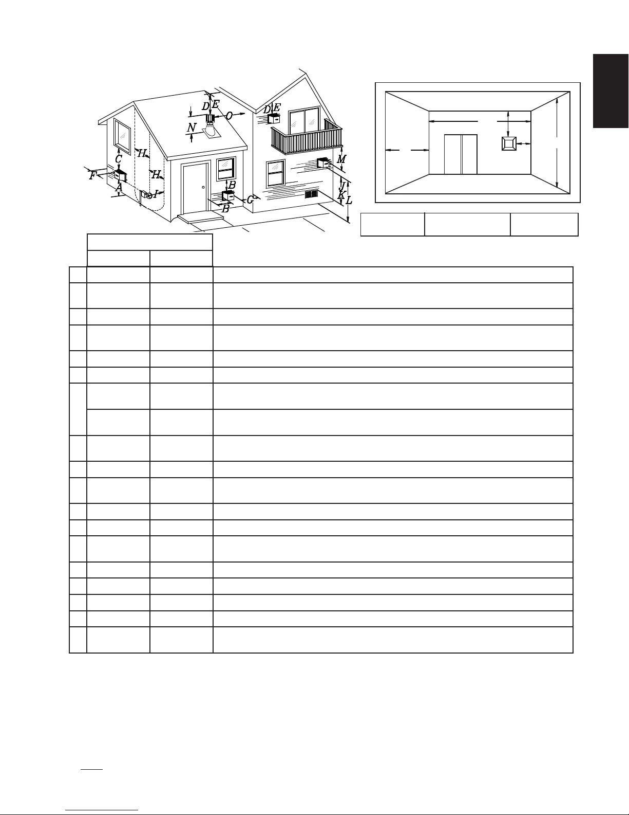
3.2 VENT TERMINAL CLEARANCES
COVERED BALCONY APPLICATIONS
Q
M
R
G
P
11
EN
Q
= 3 feet
MIN
(0.9m)
R
= 2 x
MAX
INSTALLATIONS
CANADA U.S.A.
12” (30.5cm) 12” (30.5cm) Clearance above grade, veranda porch, deck or balcony.
A
B
C
D
E
F
12”
(30.5cm)
12” (30.5cm)* 12” (30.5cm)* Clearance to permanently closed windows.
18” (45.7cm)** 18” (45.7cm)**
18” (45.7cm)** 18” (45.7cm)** Clearance to unventilated soffit.
0” (0mm) 0” (0mm) Clearance to an outside corner wall.
0” (0mm)*** 0” (0mm)***
G
2” (50.8mm)*** 2” (50.8mm)***
3’ (0.9m) 3’ (0.9m)****
H
3’ (0.9m) 3’ (0.9m) **** Clearance to a service regulator vent outlet.
I
12” (30.5cm) 9” (228.6mm)
J
6’ (1.8m) 3’ (0.9m) † Clearance to a mechanical air supply inlet.
K
7’ (2.1m) ‡ 7’ (2.1m) **** Clearance above a paved sidewalk or paved driveway located on public property.
L
M
N
O
P
Q
R
Δ
* Recommended to prevent condensation on windows and thermal breakage
** It is recommended to use a heat shield and to maximize the distance to vinyl clad soffits.
*** The periscope requires a minimum 18” (45.cm) clearance from an inside corner.
**** This is a recommended distance. For additional requirements check local codes.
† 3 feet above if within 10 feet (3.1m) horizontally.
‡ A vent shall not terminate where it may cause hazardous frost or ice accumulations on adjacent property surfaces.
†† Permitted only if the veranda, porch, or deck is fully open on a minimum of two sides beneath the floor.
†* Recommended to prevent recirculation of exhaust products. For additional requirements check local codes.
NOTE: Clearances are in accordance with local installation codes and the requirements of the gas supplier.
12”
(30.5cm)††
16” (40.6cm) 16” (40.6cm) Clearance above the roof.
2’ (0.6m)†* 2’ (0.6m)†* Clearance from an adjacent wall including neighbouring buildings.
8’ (2.4m) 8’ (2.4m)
3’ (0.9m) 3’ (0.9m) See chart for wider wall dimensions.
6’ (1.8m) 6’ (1.8m)
In a structure with three walls and a roof, the terminal shall not be located less than 6 feet (1.8m) under a window that opens on a horizontal plane.
9” (228.6mm)ΔClearance to windows or doors that open.
Δ
Vertical clearance to ventilated soffits located above the terminal within a horizontal distance of
2’ (50.8mm) from the centerline of the terminal.
Clearance to an inside non-combustible corner wall or protruding non-combustible obstructions (chimney, etc.).
Clearance to an inside combustible corner wall or protruding combustible obstructions (vent
chase, etc.).
Clearance to each side of the centerline extended above the meter / regulator assembly to a
maximum vertical distance of 15’ (4.6m).
Clearance to a non-mechanical air supply inlet to the building or a combustion air inlet to any other
appliance.
12”
(30.5cm)****
Clearance under a veranda, porch, deck or balcony.
Roof must be non-combustible without openings.
See chart for deeper wall dimensions. The terminal shall not be installed on any wall that has an
opening between the terminal and the open side of the structure.
R
Q
ACTUAL
MAX
W415-2207 / A / 08.28.17
≤ 15 feet
(4.6m)

Feet Inches Millimeters
1° 0.03 0.5 12.7
15° 0.45 6.0 152.4
For the following symbols used in the venting calculations and
examples are:
> - greater than
12
3.3 DEFINITIONS
EN
> - equal to or greater than
< - less than
< - equal to or less than
HT - total of both horizontal vent lengths (Hr) and offsets (Ho) in feet
HR - combined horizontal vent lengths in feet
HO - offset factor: .03 (total degrees of offset - 90°*) in feet
HO - offset factor: .03 (total degrees of offset - 135°*) in feet
VT - combined vertical vent lengths in feet
3.4 ELBOW VENT LENGTH VALUES
30° 0.9 11.0 279.4
45° 1.35 16.0 406.4
90°* 2.7 32.0 812.8
* The fi rst 90° offset has a zero value and is shown in the formula as - 90°
* The fi rst 45° and° offset have a zero value and is shown in the formula as -45° and -90°
respectively or -135° when combined (for 45° exit only).
12.1
W415-2207 / A / 08.28.17
REQUIRED
VERTICAL RISE
IN INCHES
(METERS) VT
0
5
(1.5)
15
(4.6)
20
(6.1)
100 (2.54)
50 (12.7)
150 (3.81)
12.5
(3.8)
57 (1447.8)
147 (3.73)
10
(3.1)
HORIZONTAL VENT RUN PLUS
H
4
V
2
REQUIRED
VERTICAL RISE
IN INCHES
(METERS) VT
0
5
(1.5)
15
(4.6)
20
(6.1)
100 (2.54)
50 (12.7)
150 (3.81)
12.5
(3.8)
57 (1447.8)
147 (3.73)
10
(3.1)
0
2.5
(0.8)5 (1.5)
7.5
(2.3)
10
(3.1)
12.5
(3.8)
15
(4.6)
40 (12.2)
10 (3.1)
20 (6.1)
30 (9.1)
17.5
(5.3)
20
(6.1)
39 (11.9)
REQUIRED
VERTICAL
RISE IN FEET
(METERS) VT
HORIZONTAL VENT RUN PLUS OFFSET IN
FEET (METERS) H
T
HORIZONTAL VENT RUN PLUS
OFFSET IN FEET (METERS) H
T
REQUIRED
VERTICAL RISE
IN INCHES
(METERS) VT
0
5
(1.5)
15
(4.6)
20
(6.1)
100 (2.54)
50 (12.7)
150 (3.81)
12.5
(3.8)
57 (1447.8)
147 (3.73)
10
(3.1)
HORIZONTAL VENT RUN PLUS
OFFSET IN FEET (METERS) H
T
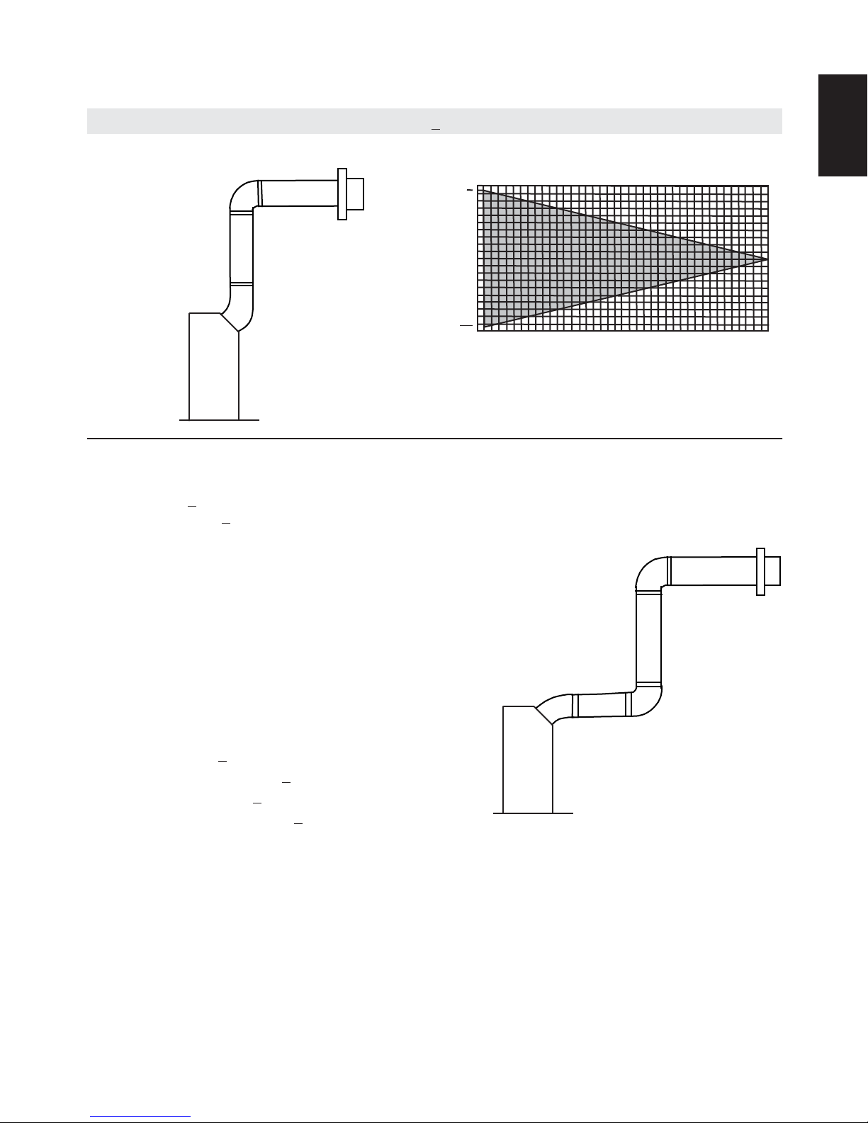
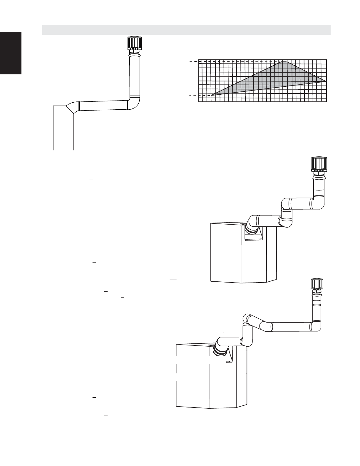
3.5 HORIZONTAL TERMINATION
13
(HT) < (VT)
Simple venting confi guration (only one 45° and 90° elbow)
See graph to determine the required vertical
EN
rise VT for the required horizontal run HT.
40 (12.2)
39 (11.9)
REQUIRED
VERTICAL
RISE IN FEET
30 (9.1)
20 (6.1)
(METERS) VT
24" (610mm)
MIN. RISE
10 (3.1)
0
2.5
(0.8)5 (1.5)
HORIZONTAL VENT RUN PLUS OFFSET IN
The shaded area within the lines represents
FEET (METERS) H
acceptable values for HT and V
7.5
(2.3)
10
(3.1)
12.5
(3.8)
15
17.5
(5.3)
20
(6.1)
T
(4.6)
T
For vent confi gurations requiring more than one 45° elbow and 90° elbow, the following formulas
apply:
Formula 1: HT < V
Formula 2: HT + VT < 40 feet (12.2m)
Example:
V
= 8 FT (2.4m)
1
VT = V1 = 8 FT (2.4m)
H1 = 2.5 FT (0.8m)
H2 = 2 FT (0.6m)
HR = H1 + H2 = 2.5 FT (0.8m) + 2 FT (0.6m) = 4.5 FT (1.4m)
HO = .03 (one 45° elbow + two 90° elbows - 135°) = .03 (225 - 135°) = 2.7 FT (0.8m)
HT = HR + HO = 4.5 FT (1.4m) + 2.7 FT (0.8m) = 7.2 FT (2.2m)
HT + VT = 7.2 FT (2.2m) + 8 FT (2.4m) = 15.2 FT (4.6m)
Formula 1: HT < V
7.2 FT (2.2m) < 8 FT (2.4m)
Formula 2: HT + VT < 40 FT (12.2m)
T
T
45°
90°
V
1
H
1
90°
H
2
15.2 FT (4.6m) < 40 FT (12.2m)
Since both formulas are met, this vent confi guration is acceptable.
W415-2207 / A / 08.28.17
REQUIRED
VERTICAL RISE
IN INCHES
(METERS) VT
100 (2.54)
50 (12.7)
150 (3.81)
57 (1447.8)
147 (3.73)
HORIZONTAL VENT RUN PLUS
Since both formulas are met, this vent confi guration is acceptable.
REQUIRED
VERTICAL RISE
IN INCHES
(METERS) VT
100 (2.54)
50 (12.7)
150 (3.81)
57 (1447.8)
147 (3.73)
40 (12.2)
10 (3.1)
20 (6.1)
30 (9.1)
39 (11.9)
REQUIRED
VERTICAL
RISE IN FEET
(METERS) VT
HORIZONTAL VENT RUN PLUS
OFFSET IN FEET (METERS) H
OFFSET IN FEET (METERS) H
EN
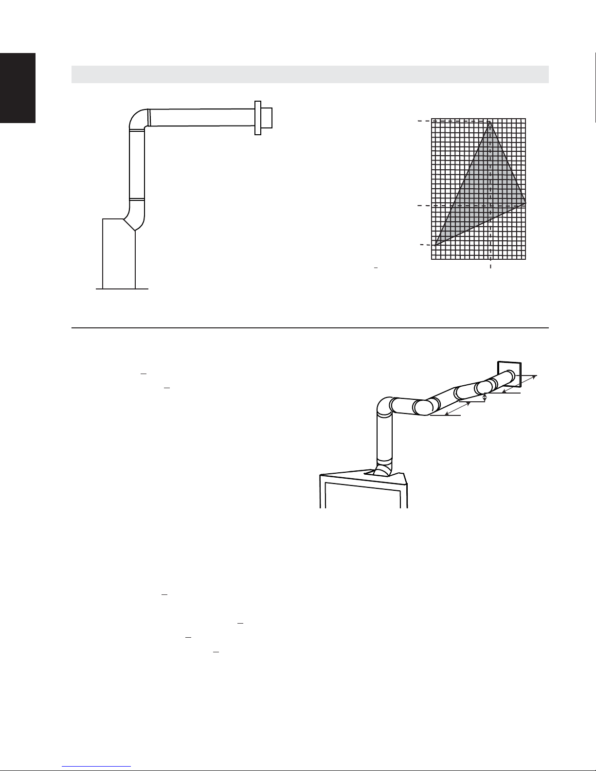
14
(HT) > (VT)
Simple venting confi guration (only one 45° and 90°
elbow)
See graph to determine the required vertical
rise VT for the required horizontal run HT.
REQUIRED
VERTICAL RISE
IN INCHES
(METERS) VT
H
T must be > 24” (610mm)
150 (3810)
150 (3.81)
147 (3733.8)
147 (3.73)
100 (2540)
100 (2.54)
57 (1447.8)
57 (1447.8)
50 (12.7)
24” (610mm)
MIN.
50 (1270)
0
5
5
0
(1.5)
(1.5)
(3.1)
10
(3.1)
12.5
(3.8)
15
15
10
(4.6)
(4.6)
12.5
(3.8)
HORIZONTAL VENT RUN PLUS
(6.1)
20
20
(6.1)
For vent confi gurations requiring more than one 45° elbow and 90° elbow, the following formulas
apply:
Formula 1: HT < 4.2 V
Formula 2: HT + VT < 24.75 feet (7.5m)
Example:
= 4 FT (1.2m)
V
1
V2 = 1.5 FT (0.5m)
VT = V1 + V2= 4 FT (1.2m) + 1.5 FT (0.5m) = 5.5 FT (1.7m)
H1 = 2 FT (0.6m)
H2 = 1 FT (0.3m)
H3 = 1 FT (0.3m)
H4 = 1.5 FT (0.5m)
HR = H1 + H2 + H3 + H4 = 2FT (0.6m) + 1FT (0.3m) + 1FT (0.3m) + 1.5FT (0.5m) = 5.5 FT (1.7m)
HO = .03 (one 45° elbow + four 90° elbows - 135°) = .03 (405 - 135°) = 8.1 FT (2.5m)
HT = HR + HO = 5.5 FT (1.7m) + 8.1 FT (2.5m) = 13.6 FT (4.2m)
HT + VT = 13.6 FT (4.2m) + 5.5 FT (1.7m) = 19.1 FT (5.8m)
Formula 1: HT < 4.2FT (1.3m) V
4.2FT (1.3m) VT = 4.2 FT (1.3m) x 5.5 FT (1.7m)= 23.1 FT (7m)
13.6 FT (4.2m) < 23.1 FT (7M)
Formula 2: HT + VT < 24.75 FT (7.5m)
19.1 FT (5.8m) < 24.75 FT (7.5m)
W415-2207 / A / 08.28.17
The shaded area within the lines represents acceptable values for HT and V
T
90°
H
1
90°
90°
H
3
V
2
H
2
T
H
4
90°
V
1
45°
T

H
= .03 (45 + 270 -
H
H
3.6 VERTICAL TERMINATION
15
Simple venting configurations.
(HT) < (VT)
See graph to determine the required vertical rise V
required horizontal run H
40 (12.2)
30 (9.1)
.
T
REQUIRED
VERTICAL
20 (6.1)
RISE IN FEET
(METERS) V
T
3 (0.9)
10 (3.1)
0
5
(1.5)
10
(3.1)
15
(4.6)
HORIZONTAL VENT RUN PLUS OFFSET IN FEET (METERS) H
The shaded area within the lines represents acceptable
values for H
and VT
T
T
20
(6.1)
EN
for the
T
For vent configurations requiring more than one 45° and one 90° elbow, the following formulas apply:
Formula 1: H
Formula 2: HT + V
< V
T
T
< 40 feet (12.2m)
T
Example:
= 5 FT (1.5m)
V
1
= 10 FT (3.1m)
V
2
V
= V
+ V
T
= 3 FT (0.9m)
H
1
H
= 2.5 FT (0.8m)
2
= H
H
R
= .03 (one 45° + three 90° elbows - 135°)
O
= H
T
+ V
T
Formula 1: H
10.9FT (3.3m) < 15 (4.6m)
Formula 2: HT + V
25.9FT (7.9m) < 40 (12.2m)
= 5 FT (1.5m) + 10 FT (3.1m) = 15 FT (4.6m)
1
2
+ H
= 3FT (0.9m) + 2.5FT (0.8m) = 5.5 FT (1.7m)
1
2
135°) = 5.4 FT (1.6m)
+ H
= 5.5 FT (1.7m)+ 5.4 FT (1.m) = 10.9 FT (3.3m)
R
O
= 10.9 FT (3.3m)+ 15 FT (4.6m) = 25.9 FT (7.9m)
T
< V
T
T
< 40 FT (12.2m)
T
45°
90°
H
1
H
V
1
90°
Since both formulas are met, this vent configuration is acceptable.
V
2
2
90°
W415-2207 / A / 08.28.17
(HT) > (VT)
for the
For vent configurations requiring more than one 45° and one 90° elbow, the following formulas apply:
Formula 1:
Formula 2:
Example:
V
V
V
H
H
H
H
= .03 (45 + 270 -
H
H
Formula 1:
3V
13.4 FT (4.1m) > 7.5 FT (2.3m)
Since this formula is not met, this vent configuration is
Formula 2:
Since only formula 2 is met, this vent configuration in unacceptable and a new fireplace location or vent
configuration will need to be established to satisfy both formulas.
Example:
V
V
V
H
H
H
H
H
= .03 (270 + 90 -
H
H
Formula 1:
3V
19.5 FT (5.9m)
Formula 2:
Since both formulas are met, this vent configuration is acceptable.
EN
16
Simple venting configurations.
REQUIRED
VERTICAL RISE
IN FEET
(METERS) V
20 (6.1)
19 (5.8)
10 (3.1)
T
3 (0.9)
See graph to determine the required vertical rise V
required horizontal run HT.
0
5
(1.5)
10
(3.1)
15
(4.6)
20
(6.1)
25
(7.6)
T
30
(9.1)
HORIZONTAL VENT RUN PLUS OFFSET IN FEET (METERS)H
The shaded area within the lines represents acceptable
values for H
HT < 3V
HT + V
= 1 FT (0.3m)
1
= 1.5 FT (0.5m)
2
= V
+ V
T
1
= 6 FT (1.8m)
1
= 2 FT (0.6m)
2
= H
R
= .03 (one 45° + three 90° elbows - 135°)
O
= H
T
+ V
T
2
+ H
1
2
+ H
R
O
= 13.4FT (4.1m)+ 2.5FT (0.8m) = 15.9FT (4.8m)
T
T
< 40 feet (12.2m)
T
= 1 FT (0.3m)+ 1.5 FT (0.5m)= 2.5 FT (0.8m)
= 6FT (1.8m) + 2FT (0.6m) = 8 FT (2.4m)
135°) = 5.4 FT (1.6m)
= 8FT (2.4m) + 5.4FT (1.6m) = 13.4FT (4.1m)
HT < 3V
T
= 3FT (0.9m) x 2.5FT(0.8m) = 7.5FT (2.3m)
T
unacceptable.
HT + V
15.9FT (4.8m) < 40FT (12.2m)
< 40 FT (12.2m)
T
45°
= 1.5 FT (0.5m)
1
= 8 FT (2.4m)
2
= V
+ V
T
= 1 FT (0.3m)
1
= 1 FT (0.3m)
2
= 10.75 FT (3.3m)
3
= H
R
= .03 (three 90° elbows + two 45° elbows - 135°)
O
= H
T
+ V
T
= 1.5 FT (0.5m) + 8 FT (2.4m) = 9.5 FT (2.9m)
1
2
+ H2 + H3 = 1FT(0.3m) + 1FT(0.3m) + 10.75FT(3.3m) = 12.75FT(3.9m)
1
135°) = 6.75 FT (2.1m)
+ H
= 12.75 FT (3.9m) + 6.75 FT (2.1m) = 19.5 FT (5.9m)
R
O
= 19.5FT (5.9m) + 9.5FT (2.9m) = 29 FT (8.8m)
T
HT < 3V
HT + V
29 FT (8.8m) < 40 FT (12.2m)
T
= 3 x 9.5 = 28.5 FT (8.7m)
T
< 40 FT (12.2m)
T
< 28.5 (8.7m)
45°
90°
V
H
1
1
H
90°
and VT
T
H
2
45°
T
V
2
90°
H
2
V
1
1
90°
90°
V
2
H
3
90°
W415-2207 / A / 08.28.17

3.7 VERTICAL THROUGH EXISTING CHIMNEY
This appliance is designed to be attached to a 3” (76.2mm) co-linear aluminum fl ex vent system running the
full length of a masonry chimney.
The fl ex liners accommodate any contours of a
masonry chimney, however, it is necessary to keep
the fl exible liners as straight as possible. The inlet air
collar of the termination cap must be connected to
the air intake fl ex liner and the exhaust collar must be
connected to the exhaust fl exible liner.
Both Simpson Duravent and Selkirk co-linear to
co-axial adaptors have been approved on this
appliance (
directly off the appliance
Follow vent manufacturer’s installation instructions.
Different manufacturer’s venting components must
not be combined. Once the preferred manufacturer’s
appliance adaptor has been attached, the
remainder of the system must be that of the
same manufacturer.
The only exception to this rule is to use Wolf
Steel’s approved 3” (76.2mm) fl ex liner and
co-linear termination.
WARNING
17
CO-AXIAL TO CO-LINEAR VENTING CONFIGURATIONS MUST ONLY BE USED IN A NON-COMBUSTIBLE
CHIMNEY OR ENCLOSURE. INSTALLATION IN A COMBUSTIBLE ENCLOSURE COULD RESULT IN A FIRE.
!
RISK OF FIRE!
TERMINATION
AIR
INTAKE
EXHAUST
FLUE
FLEX
LINER
NOTE: A vent adaptor will be required
).
* 40 FT (12.2m)
10 FT (3.1m)
EN
MAX.
MIN
* Measured from appliance fl ue collar
to termination fl ue collar
COAXIAL TO
CO-LINEAR
ADAPATOR
APPLIANCE
VENT ADAPTOR
7.6
W415-2207 / A / 08.28.17
WARNING
18
4.0 INSTALLATION
EN
!
ENSURE TO UNPACK ALL LOOSE MATERIALS FROM INSIDE THE FIREBOX PRIOR TO HOOKING UP
THE GAS AND ELECTRICAL SUPPLY.
IF YOUR APPLIANCE IS SUPPLIED WITH A REMOTE ENSURE THE REMOTE RECEIVER IS IN THE
“OFF” POSITION PRIOR TO HOOKING UP THE GAS AND ELECTRICAL SUPPLY TO THE APPLIANCE.
FOR SAFE AND PROPER OPERATION OF THE APPLIANCE, FOLLOW THE VENTING
INSTRUCTIONS EXACTLY.
ALL EXHAUST AND INTAKE VENT PIPE JOINTS MUST BE SEALED USING RED RTV HIGH TEMP
SILICONE SEALANT W573-0002 (NOT SUPPLIED) OR BLACK HIGH TEMP MILL PAC W573-0007 (NOT
SUPPLIED) WITH THE EXCEPTION OF THE APPLIANCE EXHAUST FLUE COLLAR WHICH MUST BE
SEALED USING MILL PAC.
IF USING PIPE CLAMPS TO CONNECT VENT COMPONENTS, A MINIMUM OF 3 SCREWS MUST
ALSO BE USED TO ENSURE THE CONNECTION CANNOT SLIP OFF.
DO NOT CLAMP THE FLEXIBLE VENT PIPE.
RISK OF FIRE, EXPLOSION OR ASPHYXIATION. IMPROPER SUPPORT OF THE ENTIRE VENTING
SYSTEM MAY ALLOW VENT TO SAG AND SEPARATE. USE VENT RUN SUPPORTS AND CONNECT
VENT SECTIONS PER INSTALLATION INSTRUCTIONS.
RISK OF FIRE, DO NOT ALLOW LOOSE MATERIALS OR INSULATION TO TOUCH THE VENT PIPE.
REMOVE INSULATION TO ALLOW FOR THE INSTALLATION OF THE ATTIC SHIELD AND TO
MAINTAIN CLEARANCES TO COMBUSTIBLES.
DO NOT FILL THE SPACE BETWEEN THE VENT PIPE AND ENCLOSURE WITH ANY TYPE OF
MATERIAL. DO NOT PACK INSULATION OR COMBUSTIBLES BETWEEN CEILING FIRESTOPS.
ALWAYS MAINTAIN SPECIFIED CLEARANCES AROUND VENTING AND FIRESTOP SYSTEMS.
INSTALL WALL SHIELDS AND FIRESTOPS AS SPECIFIED. FAILURE TO KEEP INSULATION OR
OTHER MATERIALS AWAY FROM VENT PIPE MAY CAUSE FIRE.
W415-2207 / A / 08.28.17
This application occurs when venting through a roof. Installation kits for
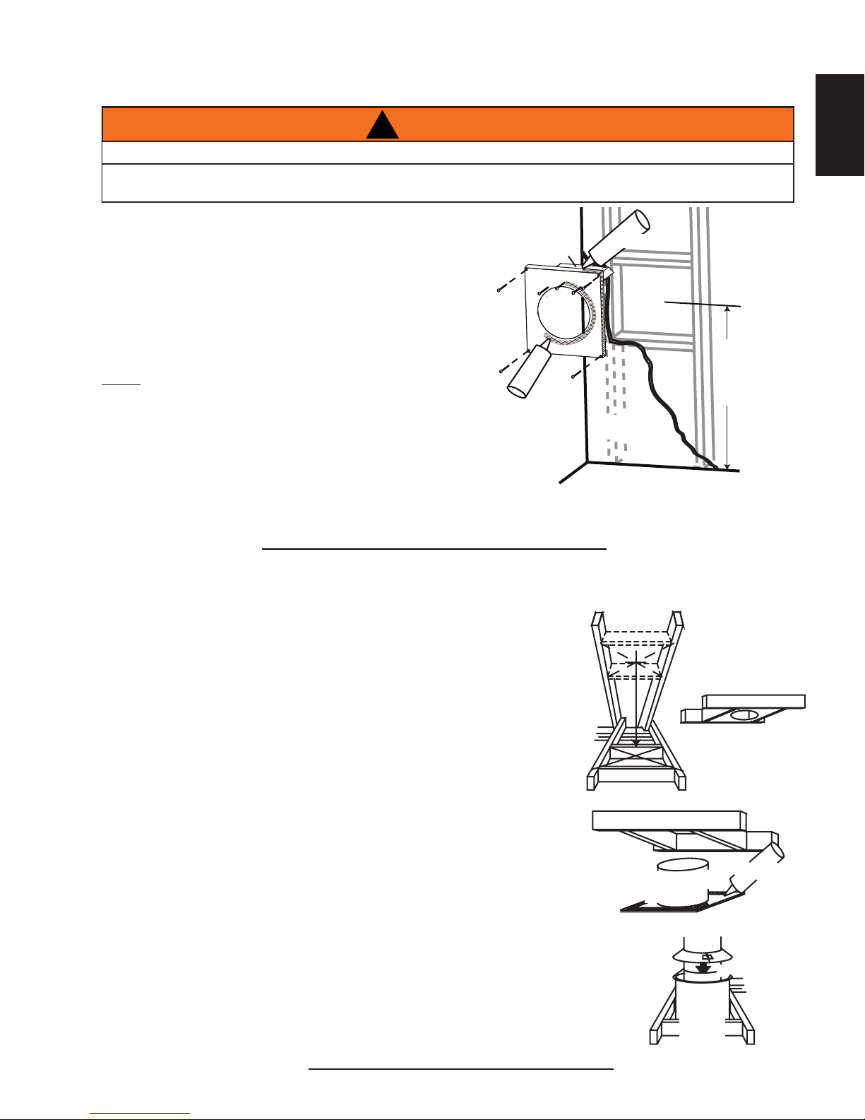
4.1 HORIZONTAL INSTALLATION
This application occurs when venting through an exterior
wall. Having determined the correct height for the air terminal
location, cut and frame a hole in the exterior wall as illustrated
to accommodate the fi restop assembly. Dry fi t the fi restop
assembly before proceeding to ensure the brackets on the
rear surface fi t to the inside surface of the horizontal framing.
The length of the vent shield may be cut shorter for
combustible walls that are less than 8 1/2” (215.9mm)
thick but the vent shield must extend the full depth of
the combustible wall.
NOTE
spacer and the exterior wall with any type of insulating
material (i.e., spray foam).
A.
B.
C.
WARNING
19
!
THE FIRESTOP ASSEMBLY MUST BE INSTALLED WITH THE VENT SHIELD TO THE TOP.
TERMINALS MUST NOT BE RECESSED INTO A WALL OR SIDING MORE THAN THE DEPTH OF THE
RETURN FLANGE OF THE MOUNTING PLATE.
VENT
SHIELD
FIRESTOP
SPACER
: Do not fi ll the air space between the fi restop
Assemble the shield to the spacer as shown, using the 3
shorter screws supplied.
Place the fi restop top so that the vent shield covers the top of
the vent within the opening. Ensure that both spacer and shield
maintain the required clearance to combustibles.
Secure the spacer in place using the 4 longer screws supplied. Once the vent pipe is installed in its fi nal
position, apply sealant between the pipe and the fi restop spacer.
CAULKING
DETERMINE
THE
CORRECT
HEIGHT
FINISHING
MATERIAL
16.4
EN
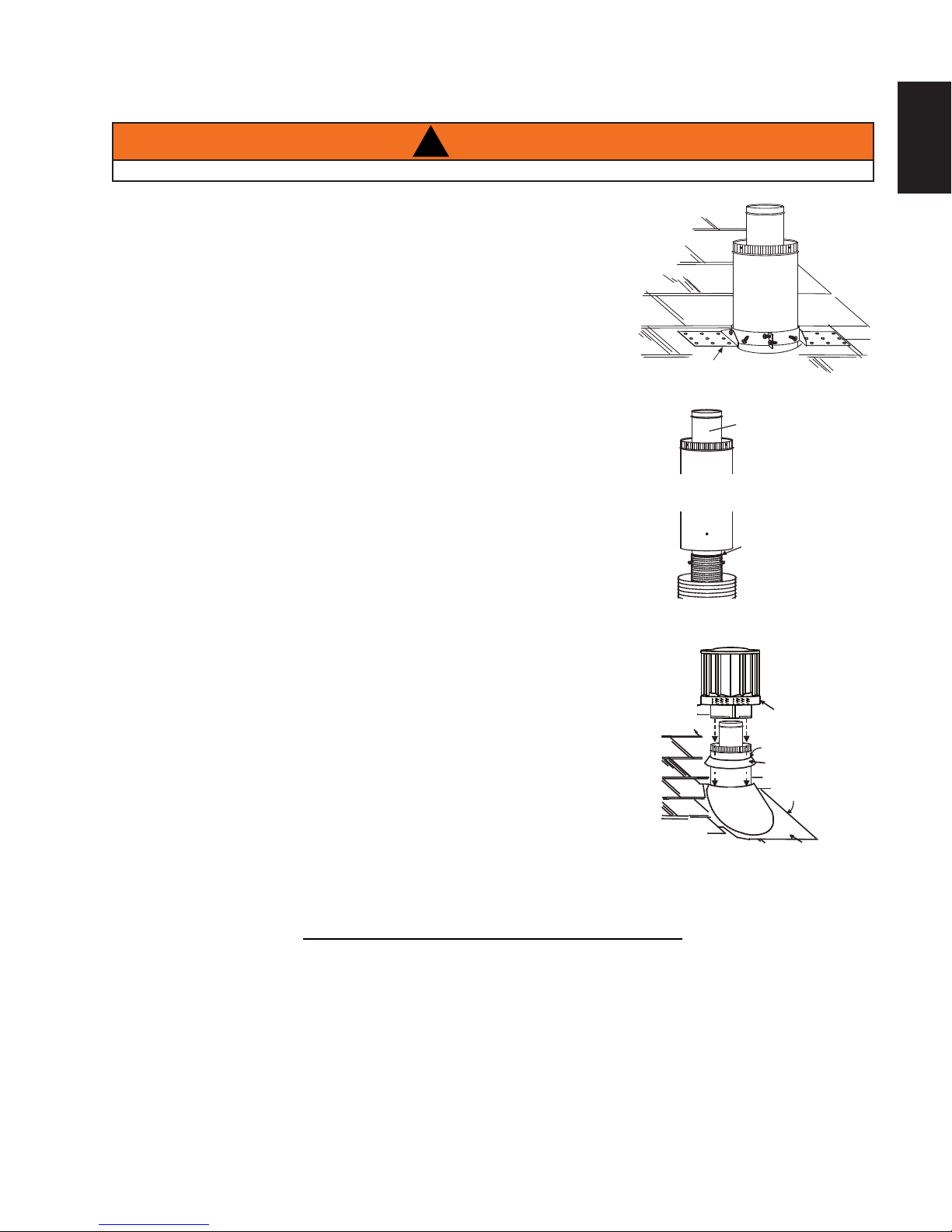
4.2 VERTICAL INSTALLATION
various roof pitches are available from your authorized dealer / distributor.
See accessories to order specifi c kits required.
A. Determine the air terminal location, cut and frame a square opening as
illustrated in the ceiling and the roof to provide the minimum 1" (25mm)
clearance between the vent pipe and any combustible material. Try to
center the vent pipe location midway between two joists to prevent
having to cut them. Use a plumb bob to line up the center of the
openings. A vent pipe shield will prevent any materials such as insulation,
from fi lling up the 1" (25mm) air space around the pipe. Nail headers
between the joist for extra support.
B. Apply a bead of caulking (not supplied) to the framework or to the Wolf
Steel vent pipe shield plate or equivalent (in the case of a fi nished ceiling),
and secure over the opening in the ceiling. A fi restop must be placed on
the bottom of each framed opening in a roof or ceiling that the venting
system passes through. Apply a bead of caulking all around and place a
fi restop spacer over the vent shield to restrict cold air from being drawn
into the room or around the fi replace. Ensure that both spacer and shield
maintain the required clearance to combustibles. Once the vent pipe is
installed in its fi nal position, apply Mill Pac sealant (W573-0007) (not
supplied) or red RTV silicone (W573-0002) (not supplied) between the
pipe and the fi restop assembly.
C. In the attic, slide the vent pipe collar down to cover up the open end of
the shield and tighten. This will prevent any materials, such as insulation,
from fi lling up the 1" (25mm) air space around the pipe.
VENT PIPE
SHIELD
VENT
PIPE
SHIELD
FIRESTOP
UNDERSIDE
OF JOIST
CAULKING
VENT
PIPE
COLLAR
16.5
W415-2207 / A / 08.28.17

A. Stretch the inner fl ex pipe to the required length taking
ADD FASTENER TYPE
to the air terminal assembly. Fasten with self tapping screws and seal.
WARNING
20
4.3 HORIZONTAL AIR TERMINAL INSTALLATION
EN
TERMINALS MUST NOT BE RECESSED INTO A WALL OR SIDING MORE THAN THE DEPTH OF THE
RETURN FLANGE OF THE MOUNTING PLATE.
DO NOT ALLOW THE INNER FLEX PIPE TO BUNCH UP ON HORIZONTAL OR VERTICAL RUNS AND
ELBOWS. KEEP IT PULLED TIGHT.
into account the additional length needed for the
fi nished wall surface. Apply a heavy bead of the Mill
Pac sealant (W573-0007) (not supplied) to the inner
sleeve of the air terminal. Slip the vent pipe a minimum
of 2” (50.8mm) over the inner sleeve of the air terminal
and secure with a minimum of 3 screws.
B. Using the outer fl ex pipe, slide over the outer
combustion air sleeve of the air terminal and secure
with a minimum of 3 screws. Seal using red RTV
silicone (W573-0002) (not supplied).
C. Insert the vent pipes through the fi restop maintaining
the required clearance to combustibles. Holding the
air terminal (lettering in an upright, readable position),
secure to the exterior wall and make weather tight by
sealing with caulking (not supplied).
D. If more vent pipe needs to be used to reach the
fi replace, couple them together as illustrated. The
vent system must be supported approximately every
3 feet (0.9m) for both vertical and horizontal runs. Use
noncombustible strapping to maintain the minimum
clearance to combustibles.
E. Stove Appliances Only: From inside the house, using Red
RTV Silicone (W573-0002) (not supplied), seal between
the vent pipe and the fi restop. Then slide the black trim collar over the vent pipe up to the fi restop.
The air terminal mounting plate may be recessed into the exterior wall or siding no greater than the
depth of its return fl ange.
!
Caulking
Screws
(Supplied)
Red RTV Silicone
Outer Flex
Pipe
Inner Flex
Pipe
2" (50.8mm) Overlap
Red RTV Silicone
Inner Flex
Pipe
18.1
Outer Flex Pipe
Screws
Inner Coupler
Outer Coupler
Outer Flex
Pipe
4.4 EXTENDED HORIZONTAL AND CORNER AIR TERMINAL INSTALLATION
FOR REAR VENT ONLY: A 45° corner installation can have 0” (0mm)
rise between the appliance combustion air collar and the air terminal.
In this case, vent lengths must be kept to a maximum of 24” (61cm).
For longer vent lengths, a minimum vertical rise of 24” (61cm) is required.
A. Follow the instructions for "HORIZONTAL AIR TERMINAL
INSTALLATIONS" section.
B. Continue adding components alternating inner rigid pipe and outer
rigid pipe. Ensure that all inner rigid pipe and elbows have sufficient
vent spacers attached and each component is sealed and securely
fastened to the one prior. Attach the inner telescopic sleeve to the
vent run. Repeat using the outer telescopic sleeve. Seal and secure
as before. To facilitate completion, attach inner and outer couplers
to the air terminal.
C. Install the air terminal. See “HORIZONTAL AIR TERMINAL
INSTALLATION” section. Extend the outer telescopic sleeve; connect
W415-2207 / A / 08.28.17
AIR TERMINAL
20" (508mm)
COUPLER
TELESCOPIC SLEEVE
Add
Image
VENTING
4.5 VERTICAL AIR TERMINAL INSTALLATION
A.
B.
C.
D.
E.
F.
G.
H.
WARNING
21
!
MAINTAIN A MINIMUM 2” (51mm) SPACE BETWEEN THE AIR INLET BASE AND THE STORM COLLAR.
Fasten the roof support to the roof using the screws provided. The
roof support is optional. In this case the venting is to be adequately
supported using either an alternate method suitable to the authority
having jurisdiction or the optional roof support.
Stretch the inner fl ex pipe to the required length. Slip the inner fl ex
pipe a minimum of 2” (51mm) over the inner pipe of the air terminal
connector and secure with a minimum of three #8 screws, when 4/7,
5/8 and 3/5 venting is used and a minimum of six #8 screws when
using 8/10 or 8/11 venting. Seal using a heavy bead of Mill Pac
sealant (W573-0007) (not supplied).
Repeat using the outer fl ex pipe, using a heavy bead of red RTV
silicone (W573-0002) (not supplied) and a minimum of three #8
screws, when 4/7, 5/8 and 3/5 venting is used and a minimum of six
#8 screws when using 8/10 or 8/11 venting.
Thread the air terminal connector / vent pipe assembly down
through the roof. The air terminal must be positioned vertically
and plumb. Attach the air terminal connector to the roof support,
ensuring that the top of the air terminal is 16” (406mm) above the
highest point that it penetrates the roof.
Remove nails from the shingles, above and to the sides of the air
terminal connector. Place the fl ashing over the air terminal connector
leaving a min. 3/4” (19mm) of the air terminal connector showing
above the top of the fl ashing. Slide the fl ashing underneath the
sides and upper edge of the shingles. Ensure that the air terminal
connector is properly centered within the fl ashing, giving a 3/4”
(19mm) margin all around. Fasten to the roof. Do not nail through
the lower portion of the fl ashing. Make weather-tight by sealing
with caulking. Where possible, cover the sides and top edges of the
fl ashing with roofi ng material.
Aligning the seams of the terminal and air terminal connector, place
the terminal over the air terminal connector making sure the vent
pipe goes into the hole in the terminal. Secure with a minimum
of three #8 screws, when 4/7, 5/8 and 3/5 venting is used and a
minimum of six #8 screws when using 8/10 or 8/11 venting.
Apply a heavy bead of weatherproof caulking 2” (51mm) above the
fl ashing. Install the storm collar around the air terminal and slide
down to the caulking. Tighten to ensure that a weather-tight seal
between the air terminal and the collar is achieved.
If more vent pipe needs to be used to reach the appliance see “HORIZONTAL AIR TERMINAL
INSTALLATION” section.
Connector
2” (51mm)
Roof Support
Inner Pipe
Air
Terminal
Red RTV
Silicone
(W572-0002)
Inner Flex Pipe
Outer Flex Pipe
Air Inlet
Base
Caulking
Sto r m Collar
Weather
Sealant
Flashing
EN
18.5
W415-2207 / A / 08.28.17

PERFORMED BY A QUALIFIED SERVICE TECHNICIAN. ASSURE THAT A CONTINUOUS GAS FLOW IS
Installation and servicing to be done by a qualifi ed installer.
Without the connector it is designed to accept a 3/8” (9.5mm) gas supply. The appliance is equipped
F. Check for gas leaks by brushing on a soap and water solution. Do not use open fl ame.
WARNING
A.
NOTE:
is not visible on the exterior pipes once installation is completed. An optional decorative black band may
be available with this appliance. In the event that the venting must be disassembled, care must be taken to
reseal the venting.
High Temperature
22
4.6 APPLIANCE VENT CONNECTION
EN
Attach the adjustable pipe to the last section of rigid pipe. Secure
with screws and seal.
B. Install the inner fl ex pipe to the appliance. Secure with a minimum of
three screws and fl at washers when installing 3”/5”, 4”/7” or 5”/8”
venting, or six screws and fl at washers when installing 8”/10” or
8”/11” venting. Seal the joint and screw holes using Mill Pac sealant
(W573-0007) (not supplied).
C. Run a bead of high temperature red RTV silicone (W573-0002)
(not supplied) around the inside of the air intake collar. Pull the
adjustable pipe a minimum 2” (50.8mm) into the air intake collar.
Always fi nish vent system installation with the appliance vent connection. Ensure that the sealant
4.7 GAS INSTALLATION
RISK OF FIRE, EXPLOSION OR ASPHYXIATION. ENSURE THERE ARE NO IGNITION SOURCES SUCH
SUPPORT GAS CONTROL WHEN ATTACHING GAS SUPPLY PIPE TO PREVENT DAMAGING GAS LINE.
ALWAYS LIGHT THE PILOT WHETHER FOR THE FIRST TIME OR IF THE GAS SUPPLY HAS RUN OUT
WITH THE GLASS DOOR OPENED OR REMOVED. PURGING OF THE GAS SUPPLY LINE SHOULD BE
!
AS SPARKS OR OPEN FLAMES.
#8 X 1/2”
Self Drilling
Screws
INSERT
IMAGE
HERE
2” (50.8mm)
Overlap
Sealant
AT THE BURNER BEFORE CLOSING THE DOOR. ENSURE ADEQUATE VENTILATION. FOR GAS AND
ELECTRICAL LOCATIONS, SEE “DIMENSION” SECTION.
ALL GAS CONNECTIONS MUST BE CONTAINED WITHIN THE APPLIANCE WHEN COMPLETE. (THIS
STATEMENT ONLY APPLIES TO GAS FIREPLACES, NOT TO GAS INSERT OR STOVE APPLICATIONS).
HIGH PRESSURE WILL DAMAGE VALVE. DISCONNECT GAS SUPPLY PIPING BEFORE TESTING GAS
VALVE SETTINGS HAVE BEEN FACTORY SET, DO NOT CHANGE.
A. Move the appliance into position and secure.
B. If equipped with a fl ex connector the appliance is designed to accept a 1/2” (13mm) gas supply.
with a manual shut off valve to turn off the gas supply to the appliance.
C. Connect the gas supply in accordance to local codes. In the absence of local codes, install to the
D. When fl exing any gas line, support the gas valve so that the lines are not bent or kinked.
E. The gas line fl ex-connector should be installed to provide suffi cient movement for shifting the burner
current CAN/CSA-B149.1 Installation Code in Canada or to the current National Fuel Gas Code,
ANSI Z223.1 / NFPA 54 in the United States.
assembly on its side to aid with servicing components.
LINE AT TEST PRESSURES ABOVE 1/2 PSIG.
W415-2207 / A / 08.28.17

4.8 MOBILE HOME
This Mobile/Manufactured Home Listed appliance comes factory equipped with a means to secure the appliance.
23
This appliance must be installed in accordance with the manufacturer’s instructions and the Manufactured
Home Construction and Safety Standard, Title 24 CFR, Part 3280, in the United States or the Mobile Home
Standard, CAN/CSA Z240 MH Series, in Canada. This appliance is only for use with the type(s) of gas
indicated on the rating plate.
Built in appliances are equipped with 1/4” (6.4mm) diameter holes located in the front left and right corners of
the base. Use appropriate fasteners, inserted through the holes in the base to secure. For free standing products
contact your local authorized dealer / distributor for the appropriate securing kit. For mobile home installations,
the appliance must be fastened in place. It is recommended that the appliance be secured in all installations.
Always turn off the pilot and the fuel supply at the source, prior to moving the mobile home. After moving the
mobile home and prior to lighting the appliance, ensure that the logs are positioned correctly.
This appliance is certifi ed to be installed in an aftermarket permanently located, manufactured (mobile)
home, where not prohibited by local codes.
This appliance is only for use with the type of gas indicated on the rating plate. This appliance is not
convertible for use with other gases, unless a certifi ed kit is used.
Conversion Kits
This appliance is fi eld convertible between Natural Gas (NG) and Propane (P).
To convert from one gas to another consult your local authorized dealer / distributor.
NOTE: Conversion Kits are not available for Vent Free Appliances.
20.1
EN
W415-2207 / A / 08.28.17
!
WARNING
MINIMUM CLEARANCE TO COMBUSTIBLES MUST BE MAINTAINED OR A SERIOUS FIRE HAZARD
COULD RESULT.
ENTIRELY OF NON-COMBUSTIBLE MATERIALS (I.E. STEEL STUDS, CEMENT BOARD, ETC.).
NEVER OBSTRUCT THE FRONT OPENING OF THE APPLIANCE.
!
WARNING
24
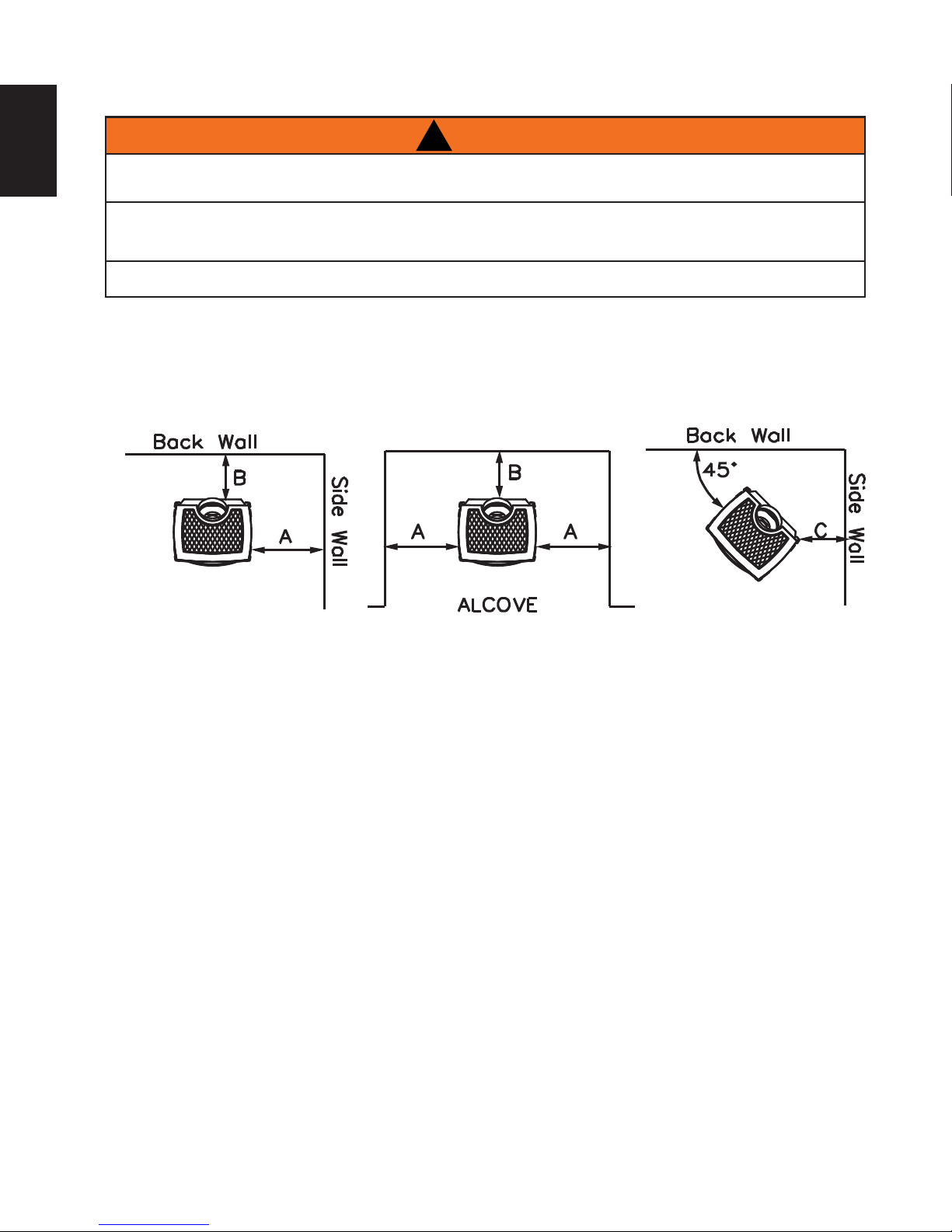
4.9 MINIMUM CLEARANCE TO COMBUSTIBLES
EN
MINIMUM CLEARANCE TO COMBUSTIBLES MUST BE MAINTAINED OR A SERIOUS FIRE HAZARD
FRAMING OR FINISHING MATERIAL CLOSER THAN THE MINIMUMS LISTED MUST BE CONSTRUCT-
ED ENTIRELY OF NON-COMBUSTIBLE MATERIALS (I.E. STEEL STUDS, CEMENT BOARD, ETC.).
NEVER OBSTRUCT THE FRONT OPENING OF THE APPLIANCE.
As long as clearance to combustibles is kept within the required distances, the most desirable and beneficial
location for a Napoleon® appliance is in the centre of a building, thereby allowing the most efficient use of
the heat created. The location of windows, doors and the traffic flow in the room where the appliance is to be
located should be considered. If possible, you should choose a location where the vent will pass through the
house without cutting a floor or roof joist.
COULD RESULT.
A. 4” (102mm) B. 2” (51mm)* C. 2” (51mm)
To ceiling from appliance top 48” (1219mm)
Horizontal vent
Sides and bottom 1” (25mm)
Top 2” (51mm)
Vertical vent
All sides 1” (25mm)
*At a distance of 2” (51mm) from the wall, installation or service to the blower may not be practical. A
minimum of 5” (127mm) will be required in order to install the blower.
If less than 5” (127mm) clearance is maintained between the back of the appliance and the back wall, it will
be necessary to disconnect the venting and gas pipe to move the appliance out for installation or service of
the blower.
W415-2207 / A / 08.28.17
COMBUSTIBLE
MANTE
TRIM M
ETC.) ARE CLEARLY MAINTAINED.
!
WARNING
25
EN
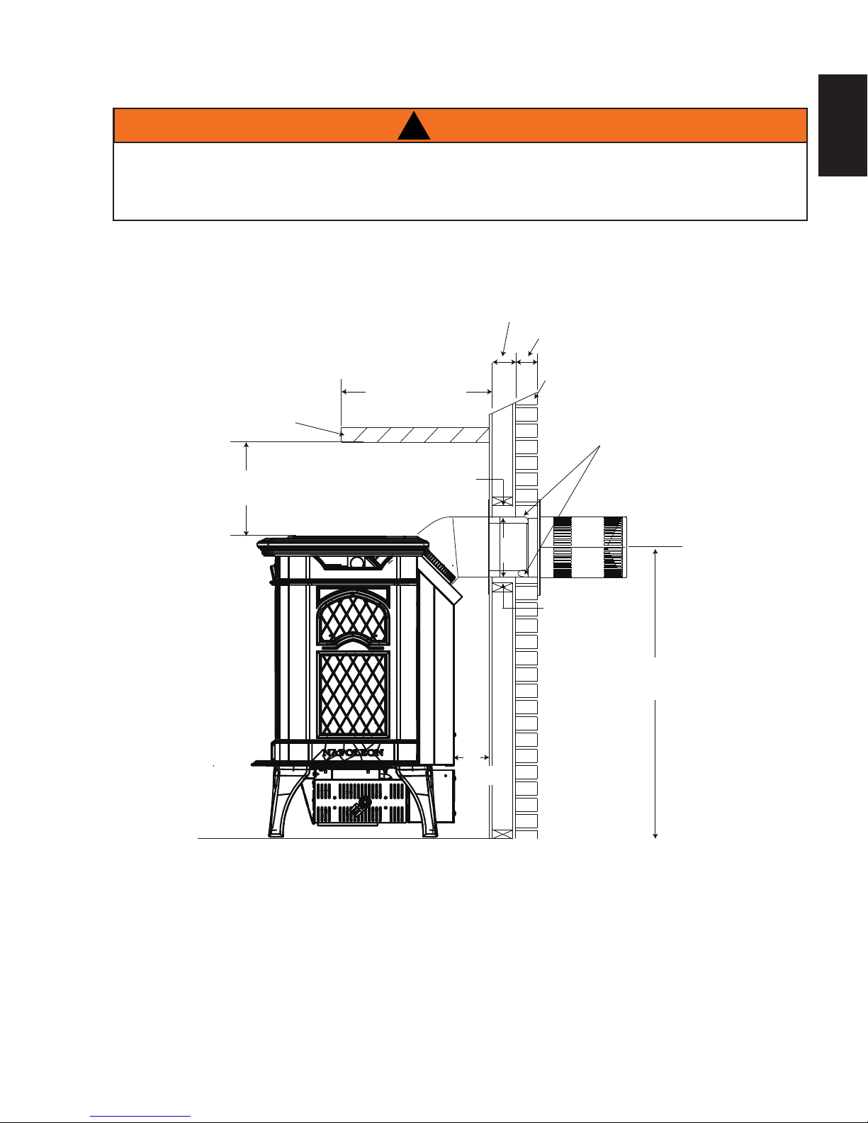
4.10 MINIMUM MANTEL OR SHELF CLEARANCES
!
WARNING
RISK OF FIRE, MAINTAIN ALL SPECIFIED AIR SPACE CLEARANCES TO COMBUSTIBLES. FAILURE
TO COMPLY WITH THESE INSTRUCTIONS MAY CAUSE A FIRE OR CAUSE THE APPLIANCE TO
OVERHEAT. ENSURE ALL CLEARANCES (I.E. BACK, SIDE, TOP, VENT, HEARTH, MANTEL, FRONT,
ETC.) ARE CLEARLY MAINTAINED.
When the appliance is rear vented, a mantel or shelf may be installed above the GDS25 at a minimum
distance of 8” (203mm).
25
EN
COMBUSTIBLE
NON-COMBUSTIBLE
L OR
ATERIAL
8” (203mm)
MIN.
12” (305mm)
MAX. MANTEL DEPTH
2” (51mm)
2”
(51mm)
BRICK
1” (25mm)
0” (0mm) IF NONCOMBUSTIBLE
FINISHING IS
USED SUCH AS
BRICK AND STONE
24.5”
(622mm)
W415-2207 / A / 08.28.17
!
WARNING
Retainer
Door
Tab
Front
Bracket
Screws
Front
Front Legs
WARNING
!
WARNING
GLASS MAY BE HOT, DO NOT TOUCH GLASS UNTIL COOLED.
the appliance.
from the side pieces by
removing the screws from
the brackets located in the
upper inside corners.
remove.
FRONT
SCREWS
BRACKET
3
2
DOOR
RETAINER
FRONT
LEGS
TAB
FRONT
!
WARNING
RISK OF FIRE!
NEVER OBSTRUCT THE FRONT OPENING OF THE APPLIANCE.
REMOVED, CRACKED, BROKEN OR SCRATCHED.
72.4
casting.
26
5.0 FINISHING
EN
DO NOT STRIKE, SLAM OR SCRATCH GLASS. DO NOT OPERATE APPLIANCE WITH GLASS
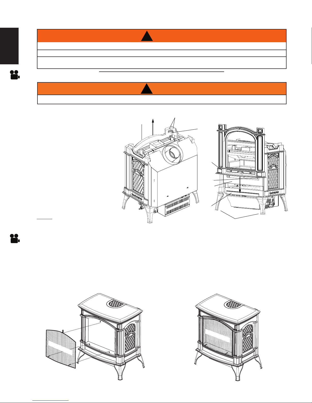
5.1 CAST FRONT INSTALLATION AND REMOVAL
5.2 SAFETY BARRIER INSTALLATION AND REMOVAL
A. Remove safety barrier.
B. Lift the top cast piece off of
the appliance.
C. Detach the front cast piece
from the side pieces by
removing the screws from
the brackets located in the
upper inside corners.
D. Slide the front straight up to
remove.
Follow the above steps in reverse
in order to reinstall the cast
front. Ensure that the tabs on the
underside of the front fit behind the
front legs.
NOTE: It is not necessary to
remove the cast front, in order to
remove the door.
A barrier designed to reduce the risk of burns from the hot viewing glass, is provided with the
appliance and shall be installed.
A. Lift the top casting up and remove the safety barrier. Remove and discard plastic.
B. Tilt the top of the safety barrier and hook under the top casting, make sure to hold the safety barrier.
C. Slightly lift the bottom of the safety barrier and push onto theappliance. Careful not to scratch the
bottom casting.
D. Reverse these steps to remove.
!
RISK OF FIRE!
NEVER OBSTRUCT THE FRONT OPENING OF THE APPLIANCE.
REMOVED, CRACKED, BROKEN OR SCRATCHED.
GLASS MAY BE HOT, DO NOT TOUCH GLASS UNTIL COOLED.
72.4
SAFETY BARRIER
W415-2207 / A / 08.28.17
SAFETY BARRIER
!
WARNING
LATCHES
DOOR
5.3 GLASS DOOR INSTALLATION AND REMOVAL
!
WARNING
DO NOT USE SUBSTITUTE MATERIALS.
GLASS MAY BE HOT, DO NOT TOUCH GLASS UNTIL COOLED.
A. Remove safety barrier.
B. Lift the top cast piece off of the appliance.
C. Pull handle and rotate 90°.
D. Slide the door straight up to remove.
Follow the above steps in reverse in order to reinstall the door. Ensure that the bottom of the door engages the door retainer before
closing the latches.
27
EN
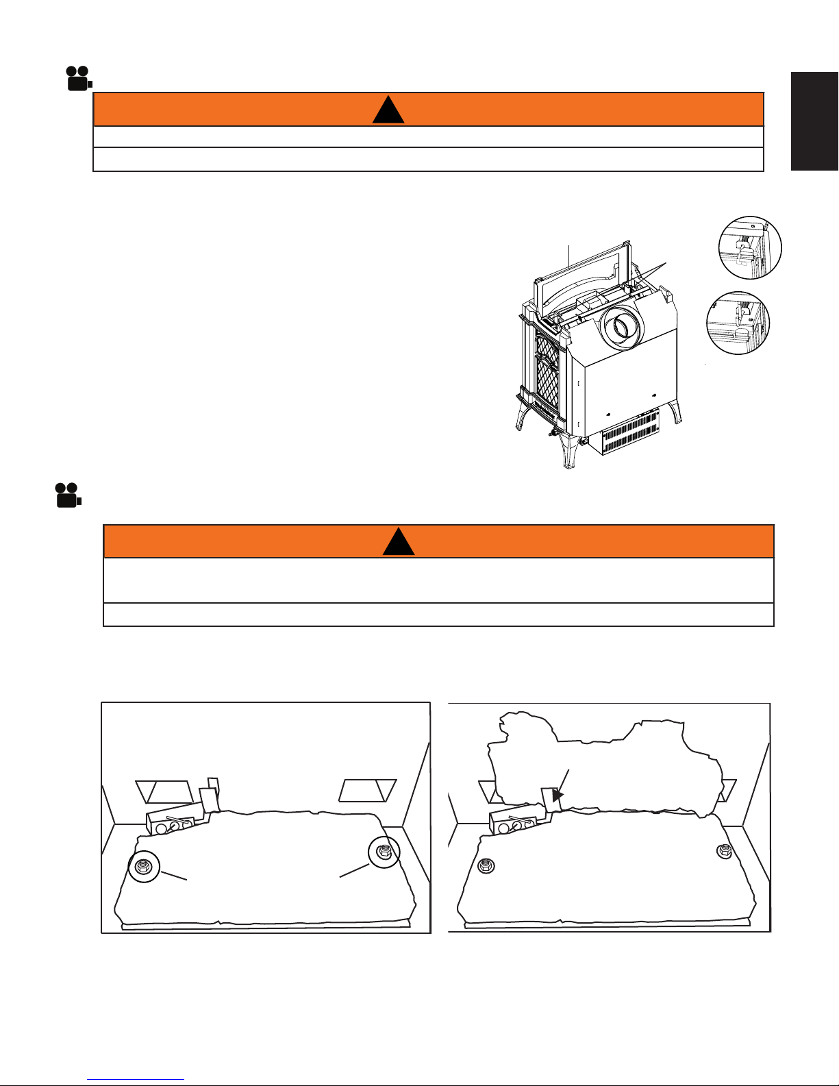
5.4 LOG PLACEMENT
LOGS MUST BE PLACED IN THE EXACT LOCATION IN APPLIANCE. DO NOT CHANGE FROM THE
PROPER LOG POSITIONS. APPLIANCE MAY NOT FUNCTION PROPERLY.
THE LOGS ARE FRAGILE AND SHOULD BE HANDLED WITH CARE.
It is not necessary to remove the cast front, however, this will make for a more simple log installation.
In order to assemble the log set, the glass door must be removed, see “CAST FRONT / GLASS DOOR
INSTALLATION AND REMOVAL” section.
BRACKET
LOG LOCATING SCREWS
A. Place the rear log, as shown, onto the rear
log support brackets. Ensure the cutout on
the left underside of the log, fits over the pilotassembly. Bend the bracket on the left side
to help retain the rear log.
W415-2207 / A / 08.28.17
MAIN
BURNER
SWITCH
ACCENT
LIGHT
SWITCH
FAN
CONTROL
LOGO
1/2”
1/2”
C. Place the hole in the underside of log #3 onto
the locating screw, on the right side of the
burner. The bottom branch of log #3 sits in
front of, and against, the right end of log #2.
D. Reinstall the glass door & front.
EN
28
B. Place the hole in the underside of log #2 onto
the locating screw, on the left side of the
burner. The fibre burner is formed to cradle
the centre of the log.
5.5 LOGO PLACEMENT
Remove the backing from the logo and position onto the control door as shown.
C. Place the hole in the underside of log #3
onto the locating screw, on the right side of
the burner. The bottom branch of log #3 sits
in front of, and against, the right end of log
#2.
D. Reinstall the glass door & front.
W415-2207 / A / 08.28.17

6.0 OPTIONAL BLOWER INSTALLATION
!
WARNING
ENSURE THEAPPLIANCE IS COMPLETELY COOL BEFORE STARTING INSTALLATION.
TO AVOID DANGER OF SUFFOCATION KEEP THE PACKAGING BAG AWAY FROM BABIES AND
CHILDREN. DO NOT USE IN CRIBS, BED, CARRIAGES, OR PLAY PENS. THIS BAG IS NOT A TOY.
KNOT BEFORE THROWING AWAY.
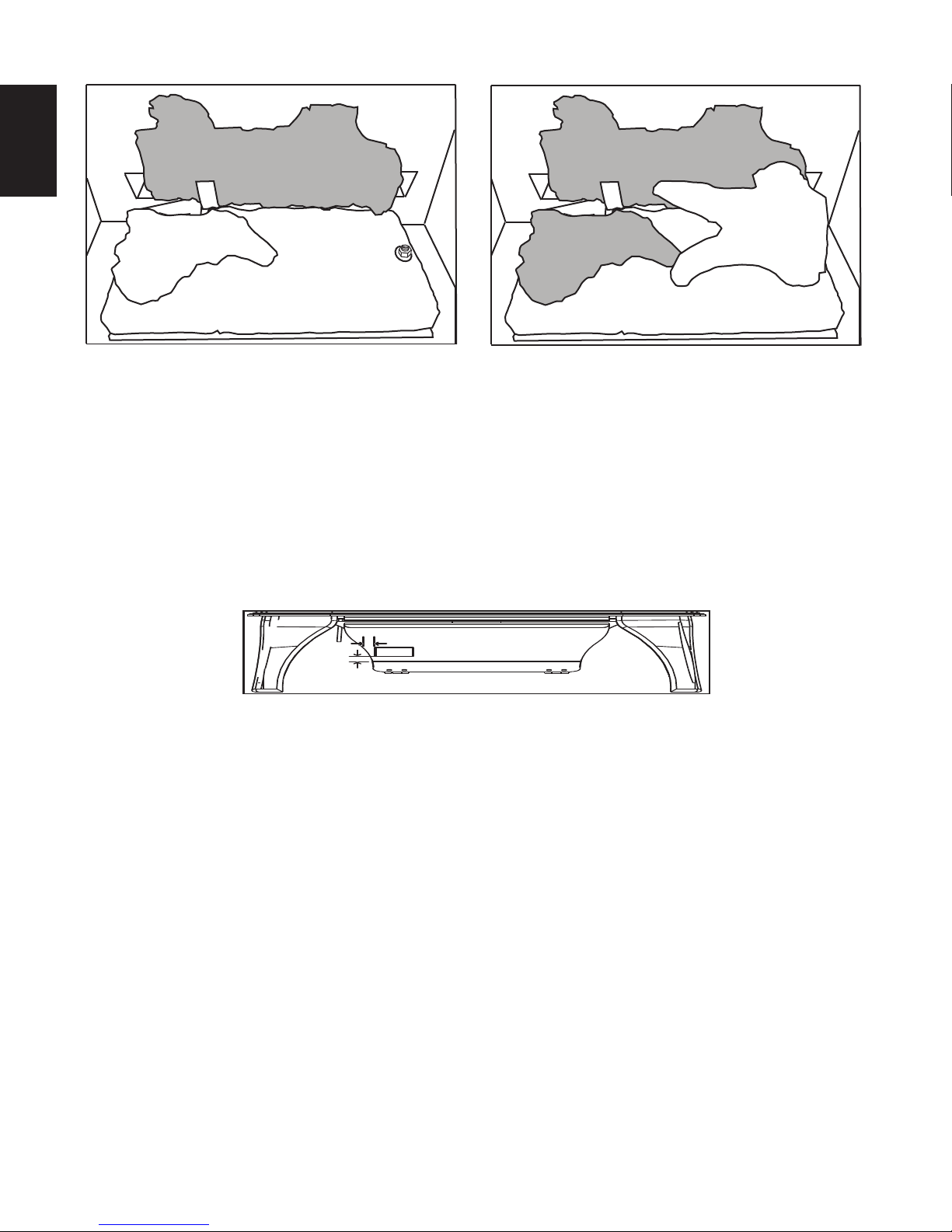
A. Disconnect power supply from the appliance.
B. Open the control door located at the bottom front of the appliance (Figure 1).
C. Remove the 2 screws holding the left control box cover (Figure 2).
D. Slide the control box cover forward and remove from the appliance (Figure 3 and 4).
29
EN
Figure 1 Figure 2
Figure 3
Figure 4
W415-2207 / A / 08.28.17
EN
30
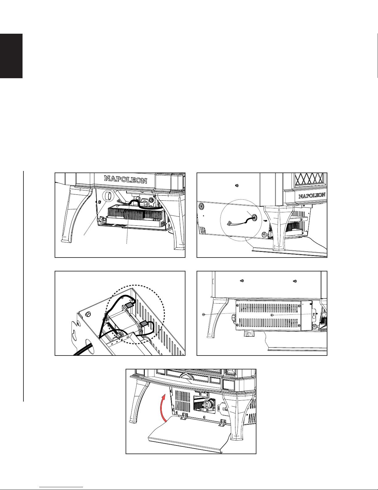
E. Access blower wire leads. Remove 2 insulation connectors from blower wire leads.
F. Route the blower wire through the rear hole of the housing (Figure 5 and 6).
G. Snap bushing over blower wire and press into rear hole of housing.
H. Place blower housing close to the rear of the appliance. Route wire through hole in blower housing and
connect the spade connectors to blower (Figure 7).
I. Align the blower to the rear side of the control box and fasten it with 2 screws included with the kit
(Figure 8).
J. Re-install control box side cover to the control box using the 2 screws previously removed in Step C.
K. Close the control door (Figure 9).
L. Reconnect power supply to the appliance.
Figure 5
Rear Hole
Figure 7
Figure 6
BUSHING
Wire Harness
Figure 8
Spade Connectors
Figure 9
W415-2207 / A / 08.28.17
 Loading...