

Napoleon Inspiration ZC, GDIZCN-SB, GDIZCP-SB Installation And Operation Manual
NATURAL GAS MODELS:
GDIZCN-SB
ADD PRODUCT CODE HERE (TRADE GOTHIC LT STD FONT)
ENGLISH
PROPANE GAS MODELS:
SAFETY INFORMATION
!
WARNING
FIRE OR EXPLOSION HAZARD
Failure to follow safety warnings exactly
could result in serious injury, death, or
property damage.
- Do not store or use gasoline or other
fl ammable vapors and liquids in the vicinity of
this or any other appliance.
- WHAT TO DO IF YOU SMELL GAS:
• Do not try to light any appliance.
• Do not touch any electrical switch; do not
use any phone in your building.
• Immediately call your gas supplier from a
neighbour’s phone. Follow the gas
supplier’s instructions.
• If you cannot reach your gas supplier, call
the fi re department.
GDIZCP-SB
FRENCH
PG. 33
INSTALLATION AND
ADD MANUAL TITLE
OPERATION MANUAL
Product Name / Code
Inspiration™ ZC
(MUST use title from Price Book)
ADD ____ ILLUSTRATED
SAFETY BARRIER
ADD PRODUCT IMAGE
- Installation and service must be
performed by a qualifi ed installer, service
agency, or the supplier.
This appliance may be installed in an aftermarket,
permanently located, manufactured home (USA
only) or mobile home, where not prohibited by
local codes.
This appliance is only for use with the type of gas
indicated on the rating plate. This appliance is
not convertible for use with other gases, unless
a certifi ed kit is used.
INSTALLER:
Leave this manual with the appliance
CONSUMER:
Retain this manual for future reference
Wolf Steel Ltd., 24 Napoleon Rd., Barrie, ON, L4M 0G8 Canada / 103 Miller Drive, Crittenden, Kentucky, USA, 41030
Phone 1 (866) 820-8686 • www.napoleon.com • hearth@napoleon.com
CSA 2.22 AND ANSI Z21.50 FOR VENTED DECORATIVE GAS APPLIANCES
CSA /
INTERTEK
LOGO
FOR INDOOR USE ONLY
CERTIFIED TO THE CANADIAN AND AMERICAN NATIONAL STANDARDS:
IF INSTALLATION + OPERATION, ADD SERIAL
NUMBER LABEL HERE
IF SEPARATE MANUALS, ADD “PLACE
BARCODE LABEL ON THE OWNER’S MANUAL”
$10.00
W415-1366 / D / 12.07.18
EN
safety information
WARNING
!
• This appliance is hot when operated and
can cause severe burns if contacted.
• Any changes or alterations to this
appliance or its controls can be
dangerous and is prohibited.
• Do not operate appliance before reading and
understanding operating instructions. Failure
to operate appliance according to operating
instructions could cause fi re or injury.
• Ensure the glass door is opened or removed
when lighting the pilot for the fi rst time and
when the gas supply has run out.
• Risk of fi re or asphyxiation, do not operate
appliance with fi xed glass removed and never
obstruct the front opening of the appliance.
• Do not connect 110 volts to the control valve,
with the exception of models; GSST8 and
GT8.
• Risk of burns. The appliance should be turned off and cooled before servicing.
• Do not install damaged, incomplete or substitute components.
• Risk of cuts and abrasions. Wear protective gloves, protective footwear, and safety glasses during
installation. Sheet metal edges may be sharp.
• Do not burn wood or other materials in this appliance.
• Provide adequate ventilation and combustion air. Provide adequate accessibility clearance for servicing
and operating the appliance.
• High pressure will damage valve. Disconnect gas supply piping before pressure testing gas line at
test pressures above 1/2 psig. Close the manual shut-off valve before pressure testing gas line at test
pressures equal to or less than 1/2 psig (35mb).
• The appliance must not be operated at temperatures below freezing (32°F / 0°C). Allow the appliance
to warm to above freezing prior to operation, with the exception of models; GSS36, GSS42; these
appliances are suitable for 0°F / -18°C.
• Children and adults should be alerted to hazards of high surface temperature and should stay
away to avoid burns or clothing ignition.
• Young children should be carefully supervised when they are in the same room as the
appliance. Toddlers, young children and others may be susceptible to accidental contact
burns. A physical barrier is recommended if there are at risk individuals in the house. To
restrict access to an appliance or stove, install an adjustable safety gate to keep toddlers,
young children and other at risk individuals out of the room and away from hot surfaces.
• Clothing or other fl ammable material should not be placed on or near the appliance.
• Due to high temperatures, the appliance should be located out of traffi c and away from
furniture and draperies.
• Furniture or other objects must be kept a minimum of 4 feet (1.22m) away from the front of the appliance.
• Ensure you have incorporated adequate safety measure to protect infants/toddlers from touching hot
surfaces.
• Even after the appliance is off, it will remain hot for an extended period of time.
• Check with your local hearth specialty dealer for safety screens and hearth guards to protect children
from hot surfaces. These screens and guards must be fastened to the fl oor.
• Any safety screen, guard or barrier removed for servicing the appliance, must be replaced prior
to operating the appliance.
• It is imperative that the control compartments, burners and circulating blower and its passageway in the
appliance and venting system are kept clean. The appliance and its venting system should be inspected
before use and at least annually by a qualifi ed service person. More frequent cleaning may be required
due to excessive lint from carpeting, bedding material, etc. The appliance area must be kept clear and
free from combustible materials, gasoline and other fl ammable vapors and liquids.
• If the appliance shuts off, do not re-light until you provide fresh air. If appliance keeps shutting off, have it
serviced. Keep burner and control compartment clean.
• Under no circumstances should this appliance be modifi ed.
• Do not allow wind or fans to blow directly into the appliance. Avoid any drafts that alter burner fl ame
patterns.
!
DANGER
HOT GLASS WILL CAUSE
BURNS.
DO NOT TOUCH GLASS UNTIL
COOLED.
NEVER ALLOW CHILDREN TO
TOUCH GLASS.
A barrier designed to reduce the risk of burns from the
hot viewing glass is provided with this appliance and
shall be installed for the protection of children and other
at-risk individuals.
2
W415-1366 / D / 12.07.18
safety information
WARNING
!
• Do not use a blower insert, heat exchanger insert or other accessory not approved for use with this
appliance.
• This appliance must not be connected to a chimney fl ue pipe serving a separate solid fuel burning
appliance.
• Do not use this appliance if any part has been under water. Immediately call a qualifi ed service technician
to inspect the appliance and to replace any part of the control system and any gas control which has
been under water.
• Do not operate the appliance with the glass door removed, cracked or broken. Replacement of the glass
should be done by a licensed or qualifi ed service person, if equipped.
• Do not strike or slam shut the appliance glass door, if equipped.
• Only doors / optional fronts certifi ed with the appliance are to be installed on the appliance.
• Keep the packaging material out of reach of children and dispose of the material in a safe manner. As
with all plastic bags, these are not toys and should be kept away from children and infants.
• Carbon or soot should not occur in a vent free appliance as it can distribute into the living area of your
home. If you notice any signs of carbon or soot, immediately turn off your appliance and arrange to have
it serviced by a qualifi ed technician before operating it again.
• If equipped, the screen must be in place (closed) when the appliance is in operation.
• When equipped with pressure relief doors, they must be kept closed while the appliance is operating
to prevent exhaust fumes containing carbon monoxide, from entering into the home. Temperatures of
the exhaust escaping through these openings can also cause the surrounding combustible materials to
overheat and catch fi re.
• Carbon monoxide poisoning may lead to death; early signs of carbon monoxide poisoning resemble the
fl u, with headache, dizziness and/or nausea. If you have these signs, the appliance may not be working
properly. Get fresh air at once! Have appliance serviced. Some people; pregnant women, persons with
heart or lung disease, anemia, those under the infl uence of alcohol, those at high altitudes are more
affected by carbon monoxide than others. Failure to keep the primary air opening(s) of the burner(s) clean
may result in sooting and property damage.
• As with any combustion appliance, we recommend having your appliance regularly inspected and
serviced as well as having a Carbon Monoxide Detector installed in the same area to defend you and
your family against Carbon Monoxide (not applicable for outdoor appliances).
• Ensure clearances to combustibles are maintained when building a mantel or shelves above the
appliance. Elevated temperatures on the wall or in the air above the appliance can cause melting,
discolouration or damage to decorations, a TV or other electronic components.
• For appliances equipped with a safety barrier; if the barrier becomes damaged, the barrier
shall be replaced with the manufacturer’s barrier for this appliance.
• Installation and repair should be done by a qualifi ed service person. It is imperative that control
compartments, burners and circulating air passageways of the appliance be kept clean.
• For outdoor products only: this appliance must not be installed indoors or within any structure that
prevents or inhibits the exhaust gases from dissipating in the outside atmosphere.
• If applicable, the millivolt version of this appliance uses and requires a fast acting thermocouple. Replace
only with a fast acting thermocouple supplied by Wolf Steel Ltd.
EN
!
WARNING:
which are known to the State of California to cause cancer, and chemicals including carbon
Add California Prop 65 warning
monoxide, which are known to the State of California to cause birth defects or other reproductive harm. For more information, go to www.P65Warnings.ca.gov.
This product can expose you to chemicals including lead and lead compounds,
!
WARNING
FIRE RISK HAZARD / DELAYED IGNITION
High supply pressure will damage the valve / controls.
Disconnect the appliance main gas valve/control
from the supply piping when pressure testing that
system at pressures in excess of 1/2 psi (3.5 kPa).
Isolate the appliance with it’s shut off valve during
any pressure testing of the supply piping at
pressures equal to or less than 1/2 psi (3.5 kPa).
!
W415-1366 / D / 12.07.18
3

EN
table of contents
1.0 general information 5
1.1 dimensions 5
1.2 minimum opening 5
1.3 general instructions 6
1.4 rates and effi ciencies 7
1.5 rating plate information 7
2.0 installation 8
2.1 levelling the appliance 8
2.2 chimney connection 9
2.3 gas installation 10
2.4 optional wall switch 10
3.0 finishing 11
3.1 minimum mantel clearances 11
3.2 safety screen & door removal and installation 12
3.3 log placement 13
3.4 glowing embers 13
3.5 logo placement 14
3.6 aluminum extrusion trim kit installation 14
4.0 operation 15
5.0 adjustments 16
5.1 pilot burner adjustment 16
5.2 venturi adjustment 16
5.3 fl ame characteristics 17
5.4 restricting vertical vents 17
6.0 maintenance 18
6.1 annual maintenance 19
6.2 care of glass 20
6.4 care of plated parts 20
6.3 door glass replacement 20
6.5 replacement blower installation 21
7.0 replacement parts 22
7.1 overview 23
7.2 valve train assembly 24
8.0 accessories 25
9.0 troubleshooting 27
10.0 warranty 29
11.0 service history 30
NOTE: changes, other than editorial, are denoted by a vertical line in the margin.
4
W415-1366 / D / 12.07.18

1.1 dimensions
1.0 general information
general information
EN
4 SIDED BACKER PLATE
ALUMINUM TRIM
SAFETY BARRIER
FRONT VIEW
20 3/4"
[527mm]
44 7/8" [1140mm]
15 1/2"
[394mm]
14"
[356mm]
36 1/2"
[927mm]
24 1/8"
[613mm]
3 SIDED BACKER PLATE
ALUMINUM TRIM
27"
[686mm]
SAFETY BARRIER
44 7/8" [1140mm]
FRONT VIEW
3 & 4 SIDED BACKER PLATES - SIDE VIEWS
25" [635mm]
15 1/2" [394mm]
11 5/8" [295mm]
7 3/8"
[187mm]
15 1/2"
[394mm]
4 15/16"
5 1/2"
[140mm]
AIR
INLET
3" [76mm] Ø
36" [914mm]
TOP VIEW
EXHAUST
10 9/16"
[268mm]
[125mm]
1.2 minimum opening
This appliance must be recessed into a vented noncombustible solid fuel-burning fi replace (prefabricated or masonry)
only. The minimum fi replace opening size in which the appliance is to be installed is:
HEIGHT 14.5" (368mm) WIDTH 25" (635mm) DEPTH 11" (279mm)
The minimum allowable chimney fl ue size is 6" (152mm) round.
W415-1366 / D / 12.07.18
5

EN
general information
1.3 general instructions
THIS GAS APPLIANCE MUST BE INSTALLED AND SERVICED BY A QUALIFIED INSTALLER to conform with local
codes. Installation practices vary from region to region and it is important to know the specifi cs that apply to your area, for
example in the state of Massachusetts:
• This product must be installed by a licensed plumber or gas fi tter when installed within the commonwealth of
Massachusetts.
• The appliance damper must be removed or welded in the open position prior to installation of an appliance insert or gas
log.
• The appliance off valve must be a “T” handle gas cock.
• The fl exible connector must not be longer than 36 inches (0.9m).
• A carbon monoxide detector is required in all rooms containing gas fi red appliances.
• The appliance is not approved for installation in a bedroom or bathroom unless the unit is a direct vent sealed
combustion product.
The installation must conform with local codes or, in absence of local
codes, the National Gas and Propane Installation Code CSA B149.1
in Canada, or the National Fuel Gas Code, ANSI Z223.1 / NFPA 54
in the United States. Suitable for mobile home installation if installed
in accordance with the current standard CAN/CSA Z240MH Series,
for gas equipped mobile homes, in Canada or ANSI Z223.1 and
NFPA 54 in the United States.
The appliance and its individual shutoff valve must be disconnected
from the gas supply piping system during any pressure testing
of that system at test pressures in excess of 1/2 psig (35 mb).
The appliance must be isolated from the gas supply piping system by closing its individual manual shutoff valve during any
pressure testing of the gas supply piping system at test pressures equal to or less than 1/2 psig (35 mb). When installed
with a blower or fan, the junction box must be electrically connected and grounded in accordance with local codes. In the
absence of local codes, use the current CSA C22.1 Canadian Electrical Code in Canada or the ANSI / NFPA 70 National
Electric Code in the United States. In the case where the blower is equipped with a power cord, it must be connected into a
properly grounded receptacle. The grounding prong must not be removed from the cord plug.
The following does not apply to inserts; as long as the required clearance to combustibles is maintained, the most desirable
and benefi cial location for an appliance is in the center of a building, thereby allowing the most effi cient use of the heat
created. The location of windows, doors and, the traffi c fl ow in the room where the appliance is to be located should be
considered. If possible, you should choose a location where the vent will pass through the house without cutting a fl oor or
roof joist. If the appliance is installed directly on carpeting, vinyl tile or other combustible material other than wood fl ooring, the
appliance shall be installed on a metal or wood panel extending the full width and depth, unless otherwise tested.
When the appliance is installed at elevations above 4,500ft (1372m), and in the absence of specifi c
recommendations from the local authority having jurisdiction, the certifi ed high altitude input rating shall be
reduced at the rate of 4% for each additional 1,000ft (305m). Expansion /
contraction noises during heating up and cooling down cycles are normal
and to be expected.
www.ncertied.org
We suggest that our gas
hearth products be installed
and serviced by professionals
who are certied in the U.S.
by the National Fireplace
®
Institute
(NFI) as NFI Gas
Specialists
6
This appliance is not approved for closet or recessed installations. It
is approved for bathroom, bedroom and bed-sitting room installations
and is suitable for mobile homes. The natural gas model is suitable for
installation in a mobile home that is permanently positioned on its site and
fuelled with natural gas.
A barrier designed to reduce the risk of burns from the hot viewing glass is provided with the
appliance and must be installed.
W415-1366 / D / 12.07.18
65.5%
GDIZC
general information
a
talled in accordaalled in acc
ns une maison mobile si son instal
s-Unis selo
eis selon la n
24 CFR, Part4 CFR, Par
NFPA 501A, Fire Safety Criteria for1A, Fire Safety Criteria fo
eil utilise et requiert un thermocouple à aceil utilise et requiert un thermocouple à a
24 Napoleon Road, Barrie24 Napoleon Road, Ba
ÉlévationÉléva
AlimentationAlimenta
A
eAlimentation R
P
CDIZC-P CDIZC-P
THIS VENTED GATHIS VENTED G
WITH AIR FILTWITH AIR FIL
WITH THEWITH THE
.UEL.
NE
Manifold Pressure
Manifold Pressure:
)10
M
Minimum Supply Pressure:
M
ximum Supply Pressure:
tible mantel
to the top of
nsions.
ATTENTION: ATTENTION:
Pour installation dans un appaPour installation dans un app
maçon
Dimensions minimDimensions min
Diamètre intérieur minimaDiamètre intérieur minim
Distance minimalDistance minima
décorative combdécorative comb
3 po,
Voir la manuelVoir la
1.4 rates and effi ciencies
NG P
Altitude (FT) 0-4,500 0-4,500
Max. Input (BTU/HR) 25,000 25,000
Min. Inlet Gas Supply Pressure 4.5" (11mb) Water Column 11" (27mb) Water Column
Max. Inlet Gas Supply Pressure 7" (17mb) Water Column* 13" (32mb) Water Column
Manifold Pressure (Under Flow Conditions) 3.5" (9mb) Water Column 10" (25mb) Water Column
Max. inlet gas supply pressure not to exceed 13" w.c.
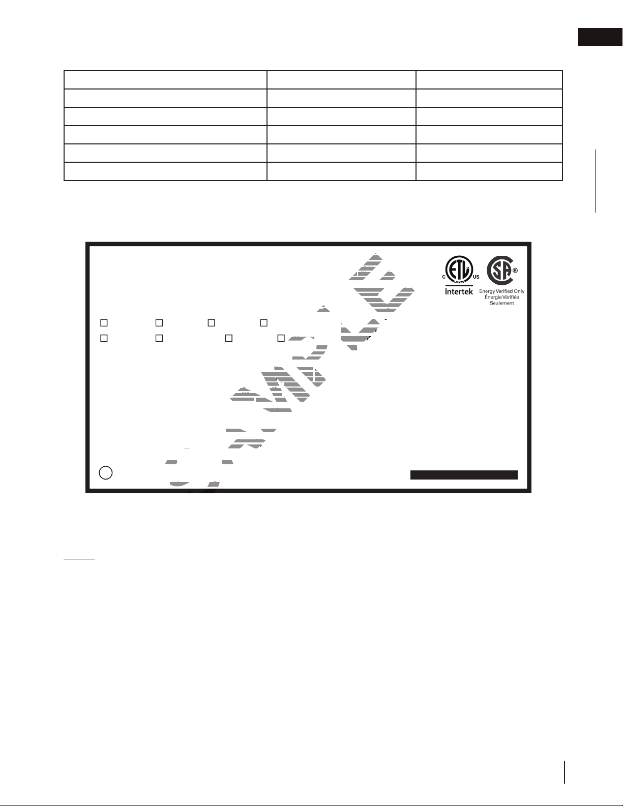
1.5 rating plate information
Certified to Canadian and American National Standards: CSA 2.22-2016 / ANSI Z21.50-2016 for Vented Decorative Gas Appliances
Certifié selon les normes Nationales Canadiennes et Américaines: CSA 2.22-2016 / ANSI Z21.50-2016 pour les Appareils à gaz décoratif à évacuation
Direct vent, vented gas fireplaces. Approved for bedroom, bathroom and bed-sitting room installation. Suitable for mobile home installation, if installed in accordance with the current
standard CAN / CSA Z240MH Series gas equipped mobile homes in Canada, or, in the United States, the Manufactured Home Construction and Safety Standard, Title 24 CFR, Part 3280.
When this US Standard is not applicable, use the Standard for Fire Safety Criteria for Manufactured Home Installations, Sites and Communities, ANSI / NFPA 501A. This appliance must be
installed in accordance with local codes, if any; if none, follow the current ANSI Z223.1 or CSA B149. For use with barrier W565-0181. Follow installation instructions. This appliance
uses and requires a fast-acting thermocouple. Replace only with a fast-acting thermocouple supplied by Wolf Steel Ltd.
Foyer à gaz ventilé. Homologué pour installation dans une chambre à coucher, une salle de bain et un studio. Approprié pour installation dans une maison mobile si son installation
conforme aux exigences de la norme CAN / CSA Z240MH Séries de maisons mobile équipées au gaz en vigueur au Canada, ou, aux États-Unis selon la norme 24 CFR, Part 3280,
Manufactured Home Construction and Safety Standard. Dans le cas ou cette norme d’États-Unis n’est pas pertinentes, utiliser la norme NFPA 501A, Fire Safety Criteria for Manufactured
Home Installations, Sites and Communities. Installer l’appareil selon les codes ou règlements locaux ou, en l’absence de tels règlements, selon les codes d’installation ANSI Z223.1 ou CSA
B149 en vigueur. Utiliser uniquement avec l’écran W565-0181. Suivre les instructions d’installation. Cet appareil utilise et requiert un thermocouple à action rapide.
Remplacez uniquement avec un thermocouple à action rapide de Wolf Steel Ltée.
9700539 (WSL) 4001658 (NAC) 4001657 (NGZ) 4001659 (WUSA)
GDIZC-N CDIZC-N GDIZC-P CDIZC-P
Altitude
Input
Reduced Input
P4
Manifold Pressure: 3.5” w.c. (NG)
Minimum Supply Pressure: 4.5” w.c. (NG)
Maximum Supply Pressure: 7” w.c. (NG)
Pression au Collecteur: 3,5” d’une colonne d’eau (GN)
Pression d’Alimentation Min.: 4,5” d’une colonne d’eau (GN)
Pression d’Alimentation Max.: 7” d’une colonne d’eau (GN)
WARNING: For installation into a vented non-combustible
appliance only.
Minimum appliance size:
Height 14 1/2”
Depth 11”
Width 25“
Minimum inside flue size:
7”
Minimum distance from bottom of a combustible mantel
projecting a maximum of 3” from the wall to the top of
standard trim:
3”
See installation manual for greater extensions.
WOLF STEEL LTD. 24 Napoleon Road, Barrie, ON, L4M 0G8 Canada
MODEL / MODÈLE
0 - 4500ft (0 - 1370m)
25,000 BTU/h
16,000 BTU/h
58.0%
Pression d’Alimentation Min.: 11” d’une colonne d’eau (P)
Pression d’Alimentation Max.: 13” d’une colonne d’eau (P)
ATTENTION: Pour installation dans un appareil ventilé en
Diamètre intérieur minimale de conduit d’évacuation:
décorative combustible, qui ressort un maximum de
Voir la manuel d’installation pour les extensions plus grandes.
Élévation
Alimentation
limentation Réduit
Alimentation Réduite
:
Manifold Pressure: 10” w.c. (P)
inimum Supply Pressure:
Minimum Supply Pressure: 11” w.c. (P)
aximum Supply Pressure:
Maximum Supply Pressure: 13” w.c. (P)
Pression au Collecteur: 10” d’une colonne d’eau (P)
Dimensions minimales de l’appareil:
Distance minimale entre le dessous d’une tablette
3 po, et le dessus de la garniture standard:
10” w.c. (P
maçonnerie seulement.
Hauteur 14 1/2”
Profondeur 11”
Largeur 25”
4
P4
7”
3”
n la norm
THIS VENTED GAS FIREPLACE HEATER IS NOT FOR USE
WITH AIR FILTERS. FOR USE WITH GLASS DOORS CERTIFIED
WITH THE APPLIANCE ONLY. NOT FOR USE WITH SOLID
FUEL.
FUEL
NE PAS UTILISER DE FILTRE À AIR AVEC CE FOYER AU GAZ À
ÉVACUATION. POUR UTILISATION UNIQUEMENT AVEC LES
PORTES EN VERRE CERTIFIÉES AVEC L’APPAREIL. NE PAS
UTILISER AVEC DU COMBUSTIBLE SOLIDE.
WARNING: Do not add any material to the appliance which will come in contact with the
flames, other than that supplied by the manufacturer with the appliance.
AVERTISSEMENT: N’ajoutez pas à cet appareil aucun matériau devant entretien
contact avec les flammes autre que celui qui est fourni avec cet appareil par le fabricant.
The appliance must be vented using the appropriate Napoleon vent kits. See installation
manual for venting specifications. Proper reinstallation and resealing is necessary after servicing
the vent-air intake system.
L’appareil doit être ventilé à l’aide de l’ensemble d’évacuation propre à Napoleon. Référez au
manuel d’installation pour les spécifications d’évacuation. Il est nécessaire de bien réinstaller et
resceller l’évacuation après avoir executer l’entretien du système de prise d’air.
Electrical rating: 115V, 60HZ. Less than 12 amperes.
Spécifications électriques: 115V, 60HZ. Moins de 12 ampère.
Serial Number / N° de Série:
GDIZC
W385-1984 / B
EN
This illustration is for reference only. Refer to the rating plate on the appliance for accurate information.
NOTE: The rating plate must remain with the appliance at all times. It must not be removed.
W415-1366 / D / 12.07.18
7

2.0 installation
EN
installation
WARNING
!
• Risk of fi re! Maintain specifi ed air space clearances to vent pipe and appliance.
Clean out ashes from the inside of the wood-burning appliance. Make sure that the chimney and wood-burning
appliance are in a clean and sound condition and constructed of non-combustible materials. If necessary have any
repair work done by a qualifi ed person before installing the insert. Remove the existing appliance damper or lock
into an open position.
Using screws, attach the appliance warning tag to the inside
of the fi rebox of the appliance into which the insert is being
installed.
The sheet-metal parts of the appliance, in which the gas
appliance insert is to be installed, must not be cut.
If the wood-burning factory-built appliance has no gas access
hole(s) provided, an access hole of 1½ inch (38.1mm) or less
may be drilled through the lower sides or bottom of the appliance in a proper workman like manner. This access
hole must be plugged with non-combustible insulation after the gas supply line has been installed.
Ensure that existing chimney cleanouts fi t properly.
The refractory, glass doors, screen rails, screen mesh and log grates may be removed from the existing appliance
before installing the gas appliance insert.
Smoke shelves, shields and baffl es may be removed if attached by mechanical fasteners.
The ventilation openings in the existing appliance may be obstructed by the backer plates, aluminium trim etc. but
these parts are not to be applied so as to have an airtight seal.
WARNING: THIS FIREPLACE HAS BEEN CONVERTED FOR USE WITH A
GAS FIREPLACE INSERT ONLY AND CANNOT BE USED FOR BURNING
WOOD OR SOLID FUELS UNLESS ALL ORIGINAL PARTS HAVE BEEN
REPLACED AND THE FIREPLACE IS RE-APPROVED BY THE AUTHORITY
HAVING JURISDICTION.
ATTENTION: CE FOYER A ETE CONVERTI AFIN D'ETRE UTILISE
SEULEMENT COMME FOYER ENCASTRE AU GAZ ET NE PEUT ETRE UTILSE
POUR BRULER DU BOIS OU TOUT AUTRE COMBUSTIBLE SOLIDE, SANS
QUE TOUTES LES PIECES ORIGINALES AIENT ETE REMPLACEES ET QUE
LE FOYER SOIT APPROUVE DE NOUVEAU PAR LES AUTORITES AYANT
JURIDICTION.
W385-0199
W385-0199
2.1 levelling the appliance
Have an authorized dealer install the appliance. If you install the appliance yourself, have your dealer review your
installation plans and/or installation. Draw out a detailed plan of the installation including dimensions and verify the
dimensions with the requirements listed in this manual.
You may wish to adjust the appliance position slightly to ensure the vent does not intersect with a framing
member. Appliance must be positioned so that no combustibles are within, or can swing within (e.g. drapes,
doors), 48” (121.9cm) of the front of the appliance.
Inserts only: This appliance is equipped with levelling screws, level the appliance before installing into the fi nal
position. Levelling the appliance will eliminate rocking or excessive noise when the fan is in operation. Once the
appliance is level, move it partially into place to allow for all connections to be made. It is not practical to level the
appliance once it has been installed. Determine the required depth prior to installing the appliance and adjust the
levelling screws accordingly.
8
W415-1366 / D / 12.07.18
installation
2.2 chimney connection
Chimney installation must conform to both national and local code requirements. The chimney must be lined with
one 2" (51mm) or 3" (76mm) diameter liner for intake and one 3" (76mm) diameter liner for exhaust. The minimum
and maximum vent lengths are 10ft (3m) and 35ft (10m) respectively. Recommended kits come in 3 lengths:
1-2" (25-51mm) & 1-3" (25-76mm) DOUBLE PLY ALUMINUM LINER-INLET AND EXHAUST &
2-3" (51-76mm) TO 2" (51mm) REDUCER:
GDI-2320KT VENT KIT 20FT (6m)
GDI-2325KT VENT KIT 25FT (7m)
GDI-2335KT VENT KIT 35FT (11m)
2-3" (50.8-76.2mm) DOUBLE PLY ALUMINUM LINER-INLET AND EXHAUST:
GDI-320KT VENT KIT 20FT (6m)
GDI-325KT VENT KIT 25 FT (7m)
GDI-335KT VENT KIT 35 FT (11m)
While the liners must be continuous from the appliance to the chimney cap, to
achieve the needed length, they may be coupled, using an approved coupler.
We recommend that exhaust vents that pass through unheated spaces, such as tall
exterior chimneys, be wrapped in a protective sleeve to minimize condensation and
reverse fl ow symptoms. See the "TROUBLESHOOTING" section for details.
This appliance is approved for use with a 2" (51mm) liner for air intake and a 3"
(76mm) liner for exhaust. For best performance, however, it is recommended to use
two 3" (76mm) liners.
If a 2" (51mm) liner is used for the intake, it may be necessary to adjust the
primary air shutter.
Exhaust
Intake
Flashing Plate
2” (51mm)
Overlap
EN
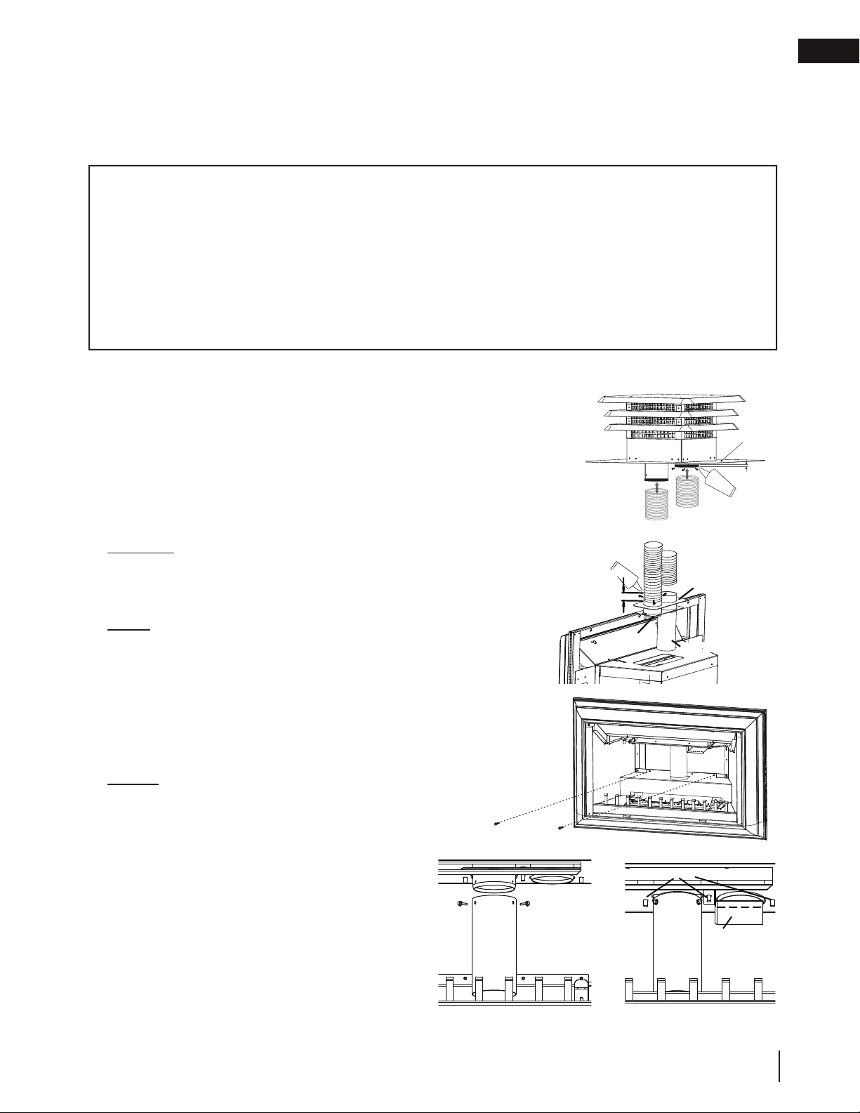
A. OUTSIDE: Slip the one end of a liner a minimum of
2"
(51mm)
over the sleeve of the air terminal. Secure
using 3 screws. Then seal the joint and screw heads
with high temperature sealant Mill-Pac (not supplied).
Repeat with the other liner.
NOTE: We recommend that the other end of the
exhaust liner be marked to eliminate the exhaust
liner being connected to the intake collar at the
appliance.
B. Gently stretch the liners to the required lengths and
insert into the chimney. Trim and fi t the fl ashing plate
to suit the chimney termination. Place the air terminal
onto the top of the chimney. Make weather tight by
sealing with caulking (not supplied). Fasten to the
chimney with screws and plugs (not supplied).
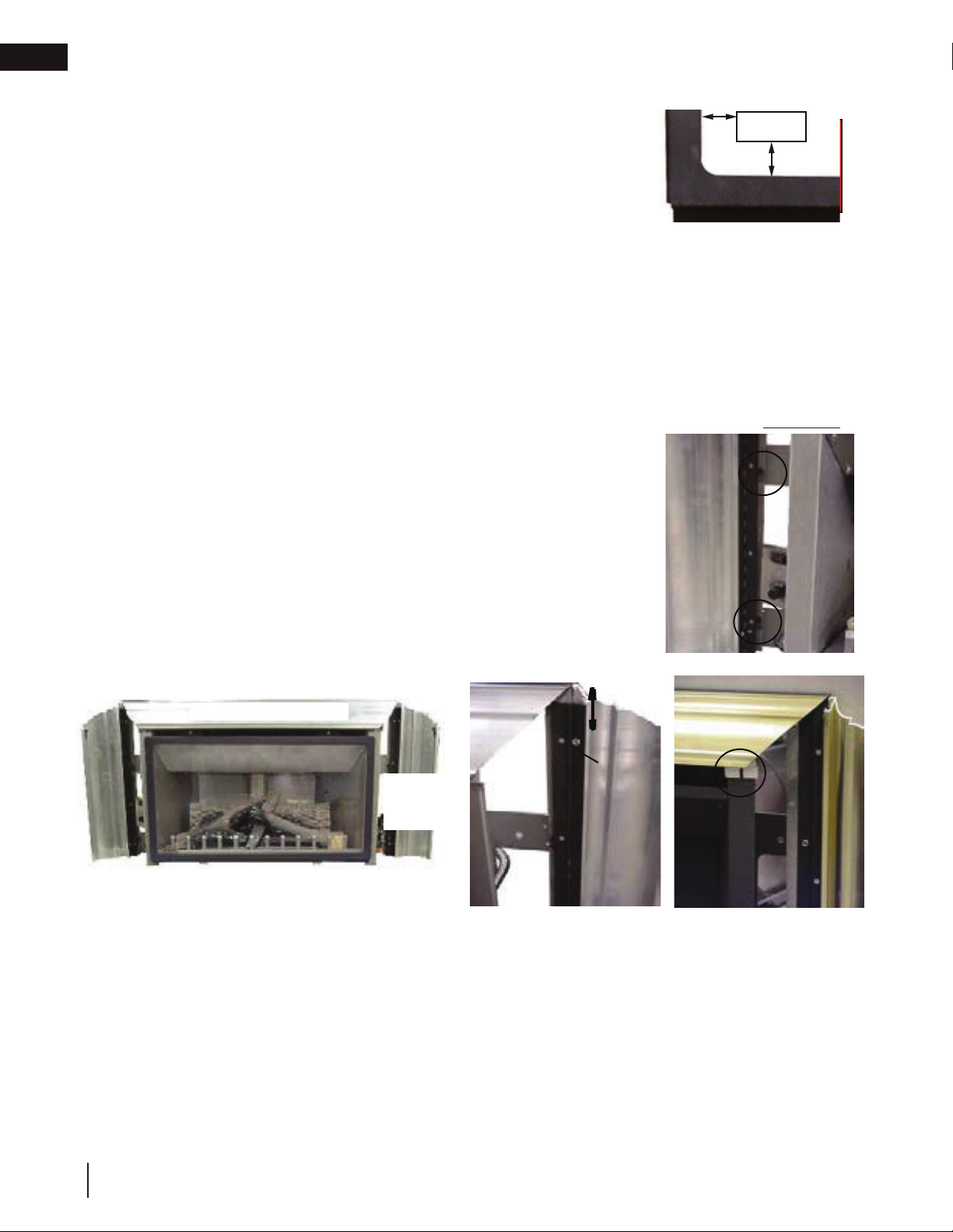
C. INSIDE: Attach and secure the fl ex liners to the vent
connection assembly using the same procedure as
before, ensuring that the marked exhaust liner is
attached to the exhaust collar.
D. Detach the two screws from the back of the fi rebox
and remove the panel, as illustrated.
E. Reaching in through the appliance, manoeuvre the
vent connection assembly through the openings in the
fi rebox top, taking care not to damage the gasket. In
case of a low ceiling fi replace, the extension should be
removed and reinstalled after the vent connection is
secured to the fi rebox. Attach the restrictor plate to the
centre stud and secure the assembly using the three
studs and 1/4-20 hex nuts.
HI-TEMP
SEALANT
2” (50.8mm)
OVERLAP
VENT
CONNECTOR
eXteNSiON
EXHAUST
VENT
CONNECTION
ASSEMBLY
INTAKE
STUDS
RESTRICTOR
PLATE
W415-1366 / D / 12.07.18
9

EN
installation
2.3 gas installation
WARNING
!
• Risk of fi re, explosion, or asphyxiation. Ensure there are no ignition sources such as sparks or open fl ames.
• Support gas control when attaching gas supply pipe to prevent damaging gas line.
• Always light the pilot whether for the fi rst time or if the gas supply has run out with the glass door opened
or removed. Purging of the gas supply line should be performed by a qualifi ed service technician. Ensure
that a continuous gas fl ow is at the burner before closing the door. Ensure adequate ventilation. For gas and
electrical locations, see “dimensions” section.
• All gas connections must be contained within the appliance when complete (gas fi replaces only).
• High pressure will damage valve. Disconnect gas supply piping before testing gas line at test pressures above
1/2 PSIG.
• Valve settings have been factory set, do not change.
Installation and servicing to be done by a qualifi ed installer.
• Move the appliance into position and secure.
• If equipped with a fl ex connector, the appliance is designed to accept a 1/2” (13mm) gas supply. Without the
connector, it is designed to accept a 3/8” (9.5mm) gas supply. The appliance is equipped with a manual shut
off valve to turn off the gas supply to the appliance.
• Connect the gas supply in accordance to local codes. In the absence of local codes, install to the current
CAN/CSA-B149.1 Installation Code in Canada or to the current National Fuel Gas Code, ANSI Z223.1 / NFPA
54 in the United States.
• When fl exing any gas line, support the gas valve so that the lines are not bent or kinked.
• The gas line fl ex-connector should be installed to provide suffi cient movement for shifting the burner assembly
on its side to aid with servicing components.
• Check for gas leaks by brushing on a soap and water solution. Do not use open fl ame.
The appliance may now be pushed into its fi nal position inside the wood burning
appliance. Secure the appliance to the fi replace using perforated strapping attached to
the two securing holes on either side of the appliance as shown. We recommend that the
trim be installed before the appliance is placed into its fi nal position.
SECURING
HOLES
2.4 optional wall switch
WARNING
!
• Do not connect either the wall switch, thermostat or gas valve directly to 110 volt electricity.
For ease of accessibility, an optional remote wall switch or millivolt thermostat may be installed in a convenient
location. Route a 2 strand, solid core millivolt wire from the valve to the wall switch or millivolt thermostat. The
recommended maximum lead length depends on wire size:
WIRE SIZE MAX. LENGTH
14 gauge (1.8mm) 100 feet (30.5m)
16 gauge (1.5mm) 60 feet (18.3m)
18 gauge (1.2mm) 40 feet (12.2m)
3
ADD IMAGE
2
HERE
1
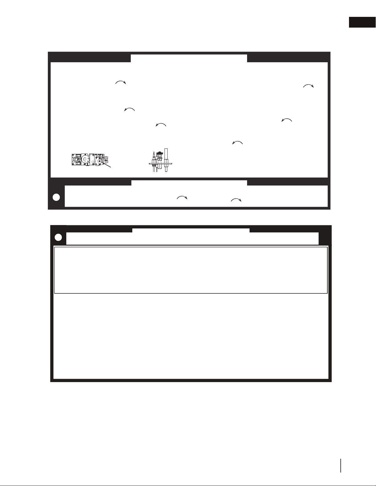
Disconnect the existing wires from terminals 1 and 3 (from the
ON/OFF switch) and replace with the leads from the wall switch / millivolt thermostat.
P
I
L
O
T
10
W415-1366 / D / 12.07.18
3.0 fi nishing
WARNING
!
• Risk of fi re!
• Never obstruct the front opening of the appliance.
• The front of the appliance must be fi nished with any non-combustible materials such as brick, marble, granite,
etc., provided that these materials do not go below the specifi ed dimension, as illustrated.
• Do not strike, slam, or scratch. Do not operate appliance with glass removed, cracked, or scratched.
• Facing and/or fi nishing material must never overhang into the appliance opening.
• The glass door assembly is a safety device designed to pivot forward when relieving excess pressure that
might occur. Finishing or other materials must not be located in the opening surrounding the door as this will
interfere with the doors ability to relieve pressure.
• If applicable, drywall dust will penetrate into the blower bearings, causing irreparable damage. Care must
be taken to prevent drywall dust from coming into contact with the blower or its compartment. Any damage
resulting from this condition is not covered by the warranty policy.
fi nishing
3.1 minimum mantel clearances
WARNING
!
• Risk of fi re. Maintain all specifi ed air space clearances to combustibles. Failure to comply with these instructions
may cause a fi re or cause the appliance to overheat. Ensure all clearances (i.e. back, side, top, vent, mantel,
front, etc.) are clearly maintained.
• When using paint or lacquer to fi nish the mantel, the paint or lacquer must be heat resistant to prevent
discolouration.
EN
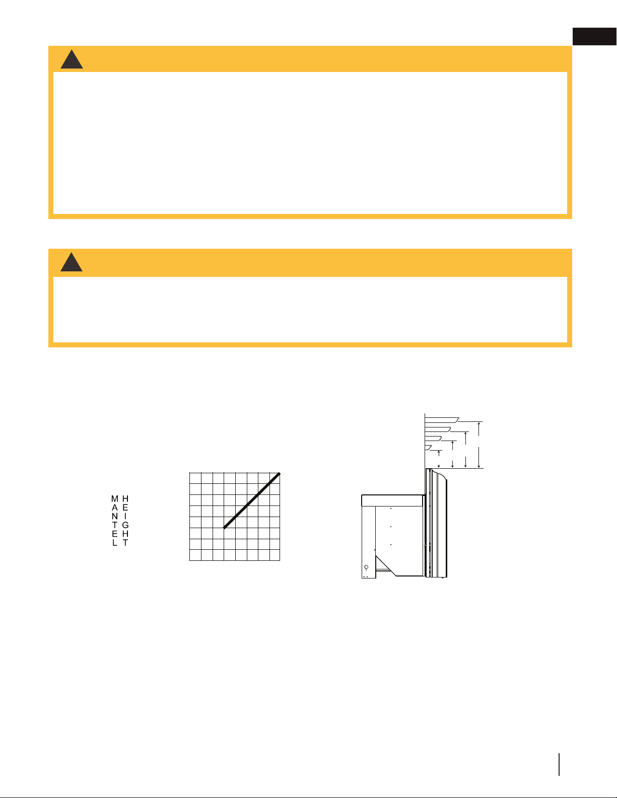
Combustible mantel clearance can vary according to the mantel depth. Use the graph to help evaluate the
clearance needed. These same requirements apply to any combustibles protruding on either side of the appliance.
6” (152mm) MANTEL
B
C
D
D
A
B
C
7” (178mm)
6” (152mm)
5” (127mm)
4” (102mm)
3” (76mm)
2” (51mm)
1” (25mm)
0
1
234567
MANTEL WIDTH
A = 6” (152mm)
B = 5” (127mm)
C = 4” (102mm)
D = 3” (76mm)
W415-1366 / D / 12.07.18
11
EN
fi nishing
3.2 safety barrier & door removal and installation
WARNING
!
• Glass may be hot. Do not touch glass until cooled.
• If equipped with door latches that are part of a safety system, they must be properly engaged. Do not
operate the appliance with latches disengaged.
• Facing and/or fi nishing materials must not interfere with air fl ow through air openings, louvre openings,
operation of louvres, or doors/access for service. Observe all clearances when applying combustible
materials.
• Before door is removed, turn the appliance off and wait until appliance is cool to the touch. Doors are heavy
and fragile so handle with care.
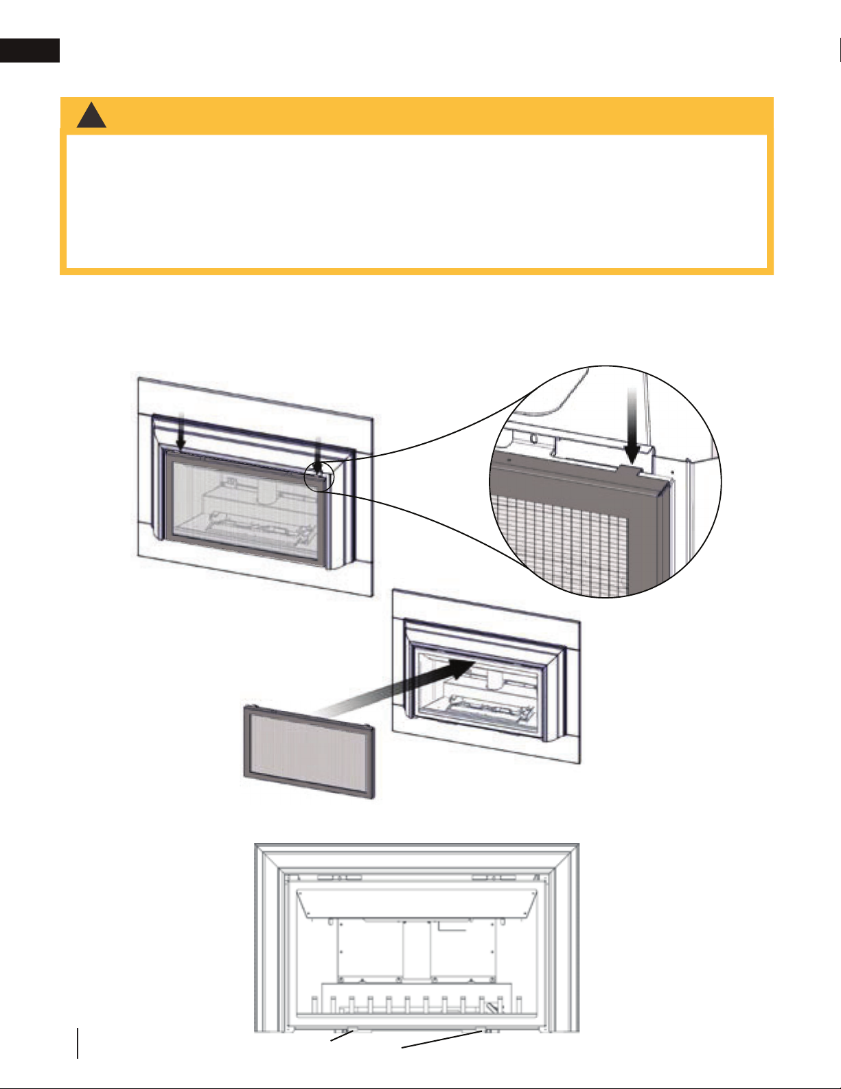
A barrier designed to reduce the risk of burns from the hot viewing glass is provided with the appliance and shall
be installed. Before the glass door can be removed, the safety barrier must be removed. Lift the safety barrier up
and remove from the appliance. Reverse these steps to reinstall the safety barrier.
ONLY:
!
ONLY:
!
Place the door into the two lower door brackets then secure at the top of the appliance with two #10-24 machine
screws. Reverse these steps to reinstall the safety barrrier and door. Ensure safety barrier is installed correctly.
12
W415-1366 / D / 12.07.18
LOWER DOOR BRACKET
fi nishing
3.3 log placement
WARNING
!
• Failure to position the logs in accordance with these diagrams or failure to use only logs specifi cally approved
with this appliance may result in property damage or personal injury.
• Logs must be placed in their exact location in the appliance. Do not modify the proper log positions, since
appliance may not function properly and delayed ignition may occur.
• The logs are fragile and should be handled with care.
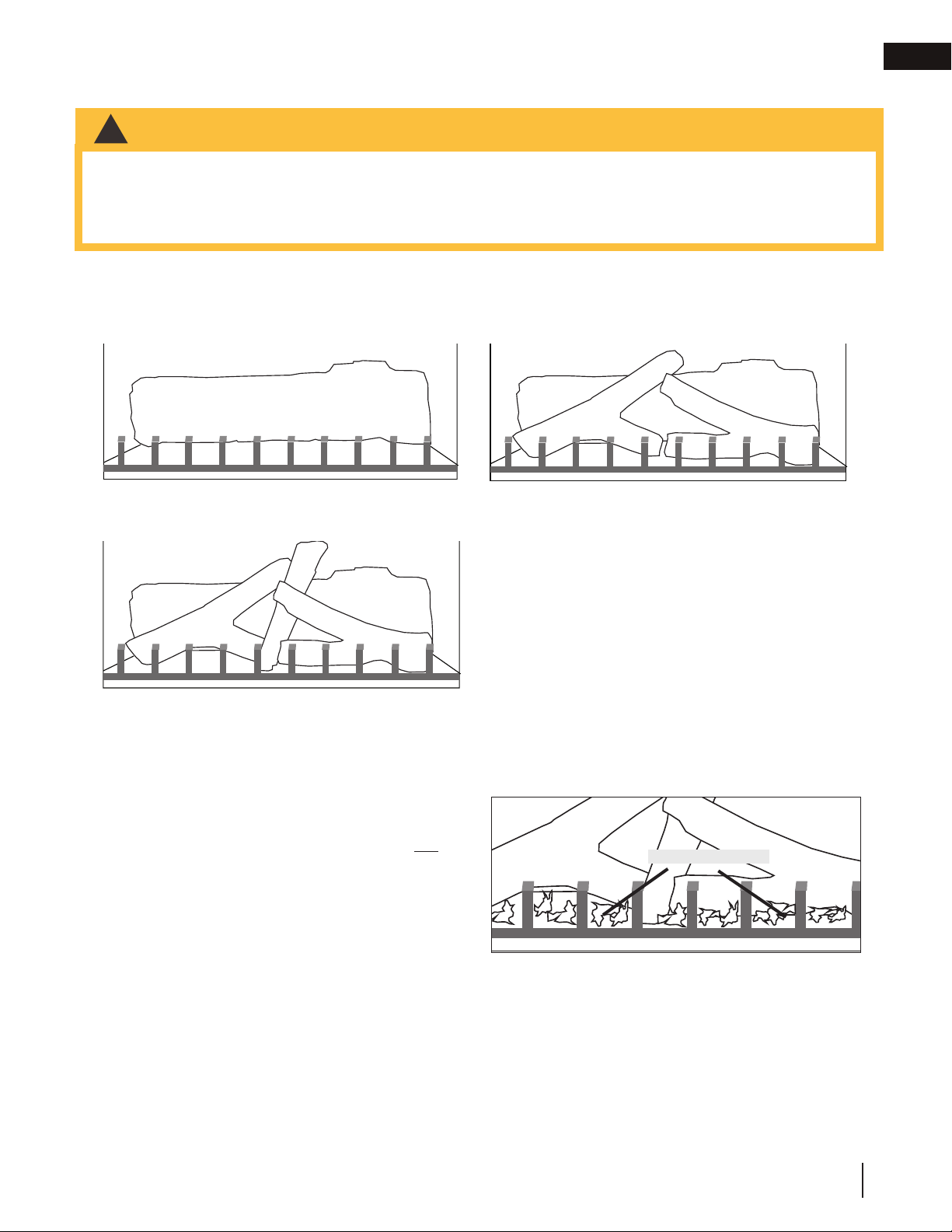
PHAZERTM logs and glowing embers exclusive to Napoleon Fireplaces, provide a unique and realistic glowing effect that is
different in every installation. Take the time to carefully position the glowing embers for a maximum glowing effect.
Log colours may vary. During the initial use of the fi replace, the colours will become more uniform as colour
pigments burn in during the heat activated curing process.
BA
B
EN
A.
Place the rear log (W135-0136) onto the two log
supports and against the air intake pipe.
B. Position the left log (W135-0137) and the right log
(W135-0138) against the grate posts and line up the
studs located on the burner with the holes on the
bottom of the logs. Keep slightly back of the front
row of ports.
C
C.
Fit the centre log (W135-0139) into place behind the
left log and into the pocket provided on the rear log.
3.4 glowing embers
Tear the embers into pieces and place along the front row
of ports covering all of the burner area in front of the logs.
Care should be taken to shred the embers into thin, small
irregular pieces as only the exposed edges of the fi bre
hairs will glow. The ember material will only glow when
exposed to direct fl ame; however, care should be
taken to not block the burner ports.
Blocked burner ports can cause an incorrect fl ame
pattern, carbon deposits and delayed ignition. PHAZERTM
logs glow when exposed to direct fl ame. Use only certifi ed "glowing embers" and PHAZERTM logs available from
your authorized dealer / distributor.
GLOWING EMBERS
W415-1366 / D / 12.07.18
13
EN
m
fi nishing
3.5 logo placement
1/2"(12.7mm)
Remove the backing of the logo supplied and place, as illustrated.
LOGO
INSERT
IMAGE
HERE
3.6 aluminum extrusion trim kit installation
In order to close off the fi replace opening or if the opening is larger than the 3- or 4-sided aluminum extrusion trim
kits, it is recommended to reduce the opening using a non-combustible material such as ceramic tile, marble,
etc. or the GIZBP6-3 or GIZBP6-4 backer plate kits. The outside edge of teh backer plate is fi nished off with
gold trim included in each kit. A deluxe fl ashing kit complete with marquis trim may also be used to complete the
installation. These fl ashing and trim combinations are available in 6 inch (152.4mm) and 9 inch (228.6mm) widths
as well as many fi nishes to accent any room decor. Mounting brackets, GIZBRKT, are required to install the
deluxe fl ashing. Detailed installation instructions are included with each kit.
If this appliance is being installed into an existing wood burning, zero clearance fi replace, then be aware of this
precaution: Any circulation air opening may be covered (with non-combustible material) but not sealed!
The appliance can be equipped with either a 3- or 4-sided trim kit to fi nish off
the fi replace opening. Slide the trim assembly over the keyholes (2 per side) and
drop into place. If installing the optional 3- or 4-sided backer plate (GIZBP6-3
or GIZBP6-4), it must be hung prior to the trim kit installation using the same
keyholes.
To adjust the trim: If the mitre is out of alignment, open each side and loosen the
two screws at either side trim hinge. Slide the trim up or down to adjust and retighten the screws. There is also a very slight in/out adjustment that can be made.
Note: Since the side panels open and close, to access the controls, a gap is
necessary at the mitre joint.
The top trim piece has an adjustable securing bracket which enables the trim to be
secured to the fi rebox shell.
1/2"(12.7
FIRE VIEWING DOOR
SLIDE TO
ADJUST
LOOSEN
SCREWS
VALVE
CONTROL
DOOR
14
W415-1366 / D / 12.07.18
The on-off switch is located behind the left side control door.
LIGHTING INSTRUCTIONS / INSTRUCTIONS D'ALLUMAGE
WHEN LIGHTING AND RE-LIGHTING, THE GAS KNOB CANNOT BE TURNED FROM PILOT
UNLESS THE KNOB IS DEPRESSED.
1. STOP! READ THE SAFETY INFORMATION ON THE OPERATING LABEL.
2. TURN OFF ALL ELECTRIC POWER TO THE FIREPLACE.
3. TURN THE GAS KNOB CLOCKWISE TO OFF.
4. WAIT FIVE (5) MINUTES TO CLEAR OUT ANY GAS. IF YOU SMELL GAS, INCLUDING
NEAR THE FLOOR, STOP! FOLLOW “B” ON THE OPERATING LABEL. IF YOU DON’T
SMELL GAS GO TO THE NEXT STEP.
5. IF FIREPLACE IS EQUIPPED WITH FLAME ADJUSTMENT VALVE TURN CLOCKWISE TO
OFF.
6. FIND PILOT LOCATED IN FRONT OF BACK LOG.
7. TURN GAS KNOB COUNTER-CLOCKWISE TO PILOT.
8. DEPRESS AND HOLD GAS KNOB WHILE LIGHTING THE PILOT WITH THE PUSH
BUTTON IGNITOR. KEEP KNOB FULLY DEPRESSED FOR ONE MINUTE, THEN
RELEASE. IF PILOT DOES NOT CONTINUE TO BURN REPEAT STEPS 3 THROUGH 7.
9. WITH PILOT LIT, TURN GAS KNOB COUNTER-CLOCKWISE TO ON.
10. IF EQUIPPED WITH FLAME ADJUSTMENT VALVE, PUSH AND TURN KNOB TO HIGH.
11. IF EQUIPPED WITH REMOTE ON-OFF SWITCH, MAIN BURNER MAY NOT COME ON
WHEN YOU TURN THE VALVE TO ON OR HIGH. REMOTE SWITCH MUST BE IN THE ON
POSITION TO IGNITE BURNER.
12. TURN ON ALL ELECTRIC POWER TO THE FIREPLACE.
GAS KNOB TO OFF
BOUTON DU GAZ A
“OFF”
LORSQUE LE GAZ EST ALLUME OU RE-ALLUME LE BOUTON DE GAZ NE PEUT PAS
ETRE TOURNE DE PILOTE A FERME A MOINS QU'IL SOIT ENFONCE.
1. ARRETEZ! LISEZ LES INSTRUCTIONS DE SECURITE SUR L’ETIQUETTE DE
2. COUPEZ L'ALIMENTATION ELECTRIQUE AU FOYER.
3. TOURNEZ LE BOUTON DE CONTROLE DU GAZ VERS LA DROITE A
4. ATTENDEZ CINQ (5) MINUTES AFIN D'EVACUER TOUT LES GAZ. SI VOUS
5. SI L'APPAREIL EST MUNI D'UNE SOUPAPE DE REGLAGE DE LA FLAMME.
6. LOCA LISEZ LA V EILLEUS E DEVENT LA BUCHE ARRIERE.
7. TOURNE LE BOUTON DU GAZ VERS LA GAUCHE A PILOTE.
8. ENFONCEZ ET GARDEZ LE BOUTON DU GAZ ENFONCE PENDANT QUE
9. LORSQUE LA VEILLEUSE EST ALLUMEE, TOURNEZ LE BOUTON DU GAZ
10. SI L'APPAREIL EST MUNI D'UNE SOUPAPE DE REGLAGE DE LA FLAMME,
11. SI L'APPAREIL EST MUNI D'UNE INTERRUPTEUR OUVERT/FERME A DISTANCE,
12. RE-ALIMENTEZ L'APPAREIL EN ELECTRICITE.
4.0 operation
FONCTIONNEMENT.
"OFF".
SENTEZ LE GAZ COMPRIS PRES DU REVETEMENT, ARRETEZ! OBSERVEZ
L'ITEM "B" SUR L’ETIQUETTE DE FONCTIONNEMENT. SI VOUS NE SENTEZ
PAS LE GAZ, CONTINUEZ A L'ETAPE SUIVANTE.
TOURNEZ LE BOUTON VER S LA DROITE A "OFF".
VOUS ALLUMEZ LA VEILLEUSE EN PRENFONCE PENDANT UNE MINUTE ET
RE-LA CHEZ-L E. SI LA VEILL EUSE NE RESTE PAS ALLUMEE, REPETEZ LES
ETAPES DE 3 A 7.
VERS LA GAU CHE A "ON".
PRESSEZ ET TOURNEZ LE BOUTON A "HIGH".
LE BRULEUR PRINCIPAL PEUT NE PAS S'ALLUMER QUAND VOUS TOURNEZ
LA SOUPAPE OUVERT OU "HIGH". L'INTERRUPTEUR A DISTANCE DOIT ETRE
EN POSITION OUVERT POUR QUE LE BRULEUR PRINCIPAL S 'ALLUM E.
operation
EN
TO TURN OFF GAS / COUPER L’ALIMENTATION EN GAZ
1. TURN OFF ALL ELECTRIC POWER TO THE FIREPLACE IF SERVICE IS TO
BE PERFORMED.
2. PU SH IN GAS CONTRO L KNOB SLIGHT LY AND TURN CLOCKWISE
TO OFF. DO NOT FORCE.
OPERATING INSTRUCTIONS / INSTRUCTIONS D'OPERATION
FOR YOUR SAFETY READ BEFORE OPERATING / POUR VOTRE SECURITE LIRE AVANT DE FAIRE FONCTIONNER
WARNING: DO NOT TURN ON IF CHILDREN OR OTHER AT RISK
INDIVIDUALS ARE NEAR THE FIREPLACE. IF YOU DO NOT FOLLOW
THESE INSTRUCTIONS EXACTLY, A FIRE OR EXPLOSION MAY RESULT
CAUSING PROPERTY DAMAGE, PERSONAL INJURY OR LOSS OF LIFE.
INITIAL LIGHTING OF THE PILOT AND MAIN BURNERS MUST BE DONE
WITH THE GLASS DOOR OFF.DO NOT CONNECT VALVE OR WALL
SWITCH TO ELECTRICITY. SEE INSTALLATION INSTRUCTIONS.
DO NOT CONNECT VALVE OR WALL SWITCH TO ELECTRICITY.
SEE INSTALLATION INSTRUCTIONS.
A. THIS FIREPLACE IS EQUIPPED WITH A PILOT WHICH MUST BE LIT BY
HAND WHILE FOLLOWING THESE INSTRUCTIONS EXACTLY.
B. BEFORE OPERATING SMELL ALL AROUND THE FIREPLACE AREA FOR GAS AND
NEXT TO THE FLOOR BECAUSE SOME GAS IS HEAVIER THAN AIR AND WILL
SETTLE ON THE FLOOR.
WHAT TO DO IF YOU SMELL GAS:
• TURN OFF ALL GAS TO THE FIREPLACE.
• OPEN WINDOWS.
• DO NOT TRY TO LIGHT ANY APPLIANCE.
• DO NOT TOUCH ANY ELECTRIC SWITCH; DO NOT USE ANY PHONE IN
YOUR BUI LDING.
• IMMEDIATELY CALL YOUR GAS SUPPLIER FROM A NEIGHBOUR’S PHONE.
FOLLOW THE GAS SUPPLIER’S INSTRUCTIONS.
• IF YOU CANNOT REACH YOUR GAS SUP PLIER, CALL THE FIRE DEPARTMENT.
C. USE ONLY YOUR HAND TO TURN THE GAS CONTROL KNOB / MANUAL SHUT-OFF
KNOB. NEVER USE TOOLS. IF THE KNOB WILL NOT TURN BY HAND, DO NOT TRY
TO REPAIR IT. CALL A QUALIFIED SERVICE TECHNICIAN. FORCE OR ATTEMPTED
REPAIR MAY RESULT IN A FIRE OR EXPLOSION.
D. DO NOT USE THIS FIREPLACE IF ANY PART HAS BEEN UNDER WATER. IMMEDI-
ATELY CALL A QUALIFIED SERVICE TECHNICIAN TO INSPECT THE FIREPLACE AND
REPLACE ANY PART OF THE CONTROL SYSTEM AND ANY GAS CONTROL WHICH
HAS BEEN UNDER WATER.
1. COUPEZ L'ALIMENTATION ELECTRIQUE AU FOYER SI LE SERVICE EST
EFFECTUE.
2. ENFONCEZ LEGEREMENT LE BOUTON DE CONTROLE DU GAZ ET TOURNEZ
VERS LA DROITE A “OFF”. NE FO RCEZ PAS.
ATTENTION:
INDIVIDUS À RISQUE SONT À PROXIMITÉ DU FOYER. QUICONQUE NE
RESPECTE PAS À LA LETTRE LES INSTRUCTIONS DANS LA PRÉSENTE
NOTICE RISQUE DE DÉCLENCHER UN INCENDIE OU UN EXPLOSION
ENTRAÎNANT DES DOMMAGES, DES BLESSURES OU LA MORT.
L’ALLUMAGE INITIAL DE LA VEILLEUSE ET DU BRÛLEUR PRINCIPAL
DOIT SE FAIRE AVEC LA PORTE VITRÉE ENLEVÉE.
NE RACCORDEZ PAS LA SOUPAPE OU L’INTERRUPTEUR MURAL A
L’ÉLECTRICITÉ. CONSULTEZ LES INSTRUCTIONS D’INSTALLATION.
A. CET APPAREIL EST MUNI D’UNE VEILLEUSE QUI DOIT ÊTRE ALLUMEÉ MANUELLEMENT.
RESPECTEZ LES INSTRUCTIONS CI-DESSOUS À LA LETTRE.
B. AVANT D’ALLUMER LA VEILLEUSE, RENIFLEZ TOUT AUTOUR DE L’APPAREIL POUR DÉCELER
UNE ODOUR DE GAZ. RENIFLEZ PRÈS DU PLANCHER, CAR CERTAINS GAZ SONT PLUS
LOURDS QUE L’AIR ET PEUVENT S’ACCUMULER AU NIVEAU DU SOL.
QUE FAIRE SI VOUS SENTEZ UN ODEUR DE GAZ :
• COUPEZ ENTIEREMENT L'ALIMENTTION DE GAZ PRINCIPALE.
• OUVREZ LES FENETRES.
• NE PAS TENTER D’ALLUMER D’APPAREIL.
• NE TOUCHEZ À AUCUN INTERRUPTEUR ; NE PAS VOUS SERVIR DES TÉLÉPHONES SE
TROUVANT DANS LE BÂTIMENT.
• APPELEZ IMMÉDIATEMENT VOTRE FOURNISSEUR DE GAZ DEPUIS UN VOISIN. SUIVEZ LES
INSTRUCTIONS DU FOURNISSEUR.
• SI VOUS NE POUVEZ REJOINDRE LE FOURNISSEUR, APPELEZ LE SERVICE DES INCENDIES.
C. NE POUSSER OU TOURNER LA MANETTE D’ADMISSION DU GAZ QU’À LA MAIN. NE JAMAIS
EMPLOYER D’OUTIL À CETTE FIN. SI LA MANETTE RESTE COINCÉE, NE TENTEZ PAS DE LA
RÉPARER; APPELEZ UN TECHNICIEN QUALIFIÉ. QUICONQUE TENTE DE FORCER LA
MANETTE OU DE LA RÉPARER PEUT PROVOQUER UNE EXPLOSION OU UN INCENDIE.
D. N’UTILISEZ PAS CET APPAREIL S’IL A ÉTÉ PLONGÉ DANS L’EAU, MÊME PARTIELLEMENT.
FAITES INSPECTER L’APPAREIL PAR UN TECHNICIEN QUALIFIÉ ET REMPLACEZ TOUTE
PARTIE DU SYSTÈME DE CONTRÔLE ET TOUTE COMMANDE QUI ONT ÉTÉ PLONGÉS DANS
L’EAU.
NE PAS ALLUMER SI DES ENFANTS OU D’AUTRES
W385-0201 / C
W415-1366 / D / 12.07.18
15
EN
5.0 adjustments
adjustments
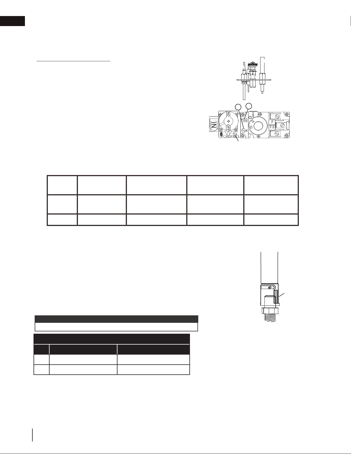
5.1 pilot burner adjustment
Adjust the pilot screw to provide properly sized fl ame. Turn in a clockwise direction to reduce the gas fl ow.
PILOT
Check Pressure Readings:
Inlet pressure can be checked by turning screw (A) counter-
THERMOCOUPLE
BURNER
THERMOPILE
clockwise 2 or 3 turns and then placing pressure gauge tubing
over the test point. Gauge should read as described on the chart
below. Check pressure with main burner operating on “HI”.
Outlet pressure can be checked the same as above using screw
(B). Gauge should read as described on the chart below. Check
pressure with main burner operating on “HI”.
After taking pressure readings, be sure to turn screws
INSERT PILOT ASSEMBLY
B
A
T
O
L
I
P
clockwise fi rmly to reseal. Do not overtorque.
Leak test with a soap and water solution.
PILOT SCREW
Prior to pilot adjustment, ensure that the pilot assembly has not been painted. If overspray or painting of
the pilot assembly has occurred remove the paint from the pilot assembly, or replace. Fine emery cloth or a
synthetic scrub pad (such as Scotch-Brite
™)
can be used to remove the paint from the pilot hood, electrode
and fl ame sensor.
Pressure Natural Gas
(inches)
Inlet
*7”
(minimum 4.5”)
Natural Gas
(millibars)
17.4mb
(minimum 11.2mb)
Propane
(inches)
13”
(minimum 11”)
Propane
(millibars)
32.4mb
(minimum 27.4mb)
Outlet
3.5” 8.7mb 10” 24.9mb
*Maximum inlet pressure not to exceed 13”
5.2 venturi adjustment
This appliance has an air shutter that has been factory set open according to
the chart below:
Regardless of venturi orientation, closing the air shutter will cause a more
yellow flame, but can lead to carbonization. Opening the air shutter will cause
a more blue flame, but can cause flame lifting from the burner ports. The flame
may not appear yellow immediately; allow 15 to 30 minutes for the final flame
colour to be established.
AIR SHUTTER ADJUSTMENT MUST ONLY BE DONE BY A QUALIFIED
INSTALLER!
note:
It is important that the orifice is securely inserted into the venturi.
AIR SHUTTER SETTING
3" / 3" Liner System 2" / 3" Liner System
NG
P
This appliance is approved for use with a 2" (51mm) liner for air intake and a 3" (76mm) liner for exhaust. For best performance,
however, it is recommended to use two 3" (76mm) liners.
1/16” (2mm) 1/8" (3mm)
3/16” (5mm) 5/16" (8mm)
VENTURI
BURNER
AIR
SHUTTER
OPENING
ORIFICE
16
W415-1366 / D / 12.07.18
5.3 fl ame characteristics
adjustments
EN
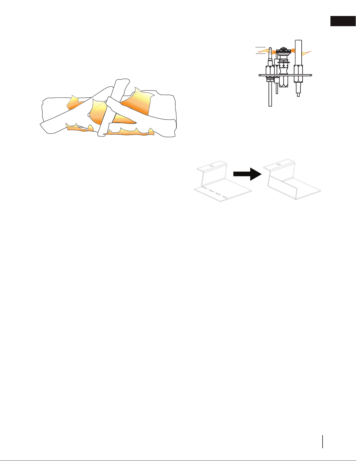
It’s important to periodically perform a visual check of
the pilot and burner flames. Compare them to the
illustration provided. If any flames appear abnormal,
call a service person.
5.4 restricting vertical vents
Some vent confi gurations may display a very active fl ame.
If this appearance is not desirable, the vent exit may be
restricted using a restrictor plate. Bend the fl ap up as shown
to reduce the velocity of the exhaust gases, slowing down the
fl ame pattern and creating a more traditional appearance.
(9.5mm - 12.7mm)
Flame must envelop
(12.7mm - 9.5mm) of
3/8” - 1/2”
ADD IMAGE
upper
3/8" to 1/2"
thermocouple &
thermopile
HERE
W415-1366 / D / 12.07.18
17

6.0 maintenance
EN
maintenance
WARNING
!
• Turn off the gas and electrical power before servicing the appliance.
• Appliance may be hot. Do not service until appliance has cooled.
• Do not use abrasive cleaners on glass.
• Do not paint the pilot assembly.
This appliance and its venting system should be inspected before use and at least annually by a qualifi ed
service person. The following suggested checks should be performed by a qualifi ed technician. The appliance
area must be kept clear and free of combustible materials, gasoline, or other fl ammable vapors and liquids.
The fl ow of combustion and ventilation air must not be obstructed.
note:
Caution: Label all wires prior to disconnection when servicing controls. Wiring errors can cause improper and
dangerous operation. Verify proper operation after servicing.
1. In order to properly clean the burner and pilot assembly, remove the logs, rocks and/or glass to ex-
pose both assemblies.
2. Keep the control compartment, media, burner, air shutter opening and the area surrounding the appli-
ance clean by vacuuming or brushing, at least once a year.
3. Check to see that all burner ports are burning. Clean out any of the ports which may not be burning
or are not burning properly.
4. Check to see that the pilot fl ame is large enough to engulf the fl ame sensor and/or thermocouple /
thermopile as well as it reaches the burner.
5. If your appliance is equipped with a safety barrier, cleaning may be necessary due to excessive lint /
dust from carpeting, pets, etc. simply vacuum using the brush attachment.
6. If your appliance is equipped with relief doors, ensure the system performs effectively. Check that the
gasket is not worn or damaged. Replace if necessary.
7. Replace the cleaned logs, rocks or glass. Failure to properly position the media may cause carboning
which can be distributed in the surrounding living area, inside the fi rebox and on exterior surfaces surrounding vent termination.
8. Check to see that the main burner ignites completely on all ports when turned on. A 5 to 10 second
total light-up period is satisfactory. If ignition takes longer, consult your local authorized dealer / distributor.
9. Visually inspect the appliance for carbon build up. Using a small whisk or brush, brush off the carbon
and vacuum up or sweep into garbage.
10. This step is not applicable for Vent Free appliances: Check to see that the appliance is vent-
ing correctly. Ensure chimney system is safe and unobstructed. (If for any reason the vent air intake
system is disassembled, re-install and re-seal per the instructions provided for the initial installation).
18
W415-1366 / D / 12.07.18

maintenance
6.1 annual maintenance
WARNING
!
• Annual maintenance should be performed by a qualifi ed service technician
• The fi rebox becomes very hot during operation. Let the appliance cool completely or wear heat resistant
gloves before conducting service.
• Never vacuum hot embers.
• Do not paint the pilot assembly
• This appliance will require maintenance which should be planned on an annual basis.
• Service should include cleaning, battery replacement, venting inspection and inspection of the burner,
media, and fi rebox. Refer to the door removal section and remove the door as instructed.
• Carefully remove media if necessary (logs, glass, brick panels, etc.).
• Using a vacuum with soft brush attachment, gently remove any dirt, debris, or carbon build up from the
logs, fi rebox, and burner. For glass media, follow the installation instructions for pre-cleaning.
• Gently remove any build-up on the pilot assembly including thermopile, thermocouple, fl ame sensor, and
igniter (if equipped).
note:
Clean fl ame sensor using a fi ne emery cloth or a synthetic scrub pad (such as Scotch-Brite™) to remove any
oxides. Clean the pilot assembly using a vacuum with a soft brush attachment. It is important that the pilot
assembly is not painted.
EN
• Inspect all accessible gaskets and replace as required.
• If equipped with a blower, access the blower and clean using a soft brush and vacuum.
• Re-assemble the various components in reverse order.
• Inspect the relief system. The appliance relieves through the main glass door or through the fl aps on the
fi rebox top. Ensure they open freely, and close sealed.
• Check the gas control valve pilot and Hi / Lo knobs move freely, if equipped. Replace if any stiffness in
movement is experienced.
• Check for gas leaks on all gas connections up and downstream from the gas valve including pilot tube
connections.
W415-1366 / D / 12.07.18
19
EN
maintenance
6.2 care of glass
WARNING
!
• Do not clean glass when hot! Do not use abrasive cleaners to clean glass.
Buff lightly with a clean dry soft cloth to remove accumulated dust or fi ngerprints. Clean both sides of the glass
after the fi rst 10 hours of operation with an ammonia-free glass cleaner.
note:
Vinegar-based glass cleaners have demonstrated an ability to provide a clean, streak free glass surface.
Thereafter, clean as required. If the glass is not kept clean permanent discoloration and / or blemishes may
result. Contact you local authorized dealer / distributor for complete cleaning instructions.
Razor blades, steel wool, or other metallic objects must not be used on both surfaces of the glass. Doing so
can remove a thin layer of metal from the razor blades, steel wool, or other metallic objects that may then be
deposited onto the coating. This can result in a discoloured stain or scratch-like mark. More importantly, this can
scratch the glass surface, thereby reducing its strength.
Do not operate the appliance with broken glass, as leakage of fl ue gases may result.
Contact your local authorized dealer / distributor for complete cleaning instructions.
If the glass should ever crack or break while the fi re is burning, do not open the door until the fi re is out. Do not
operate the appliance until the glass has been replaced. Contact you local authorized dealer / distributor for
replacement parts. DO NOT SUBSTITUTE MATERIALS.
This appliance is factory equipped with 5mm ceramic glass. Use only replacement parts as supplied by the
appliance manufacturer. DO NOT SUBSTITUTE MATERIALS.
6.3 care of plated parts
If the appliance is equipped with plated parts, you must clean fi ngerprints or other marks from the plated surfaces
before operating the appliance for the fi rst time. Use an ammonia-free or vinegar-based cleaner and a towel
to clean. If not cleaned properly before operating for the fi rst time, the marks can cause permanent blemishes
on the plating. After the plating is cured, the fi ngerprints and oils will not affect the fi nish and little maintenance
is required, just wipe clean as needed. Prolonged high temperature burning with the door ajar may cause
discolouration on plated parts.
note:
The protective wrap on plated parts is best removed when the assembly is at room temperature but this can
be improved if the assembly is warmed (i.e. using a hair dryer or similar heat source).
6.4 door glass replacement
WARNING
!
• Do not use substitute materials.
• Glass may be hot. Do not touch glass until cooled.
• Care must be taken when removing and disposing of any broken door glass or damaged components. Be
sure to vacuum up any broken glass from inside appliance before operation.
• Do not strike, slam, or scratch. Do not operate appliance with glass removed, cracked, broken, or scratched.
Replacement glass/frame assembly shall be replaced as a complete unit as supplied by the appliance
manufacturer.
20
W415-1366 / D / 12.07.18
 Loading...