

Napoleon GDS 50 - N, GDI 50 - N, GDI 50 - P, GDS 50 - P, GS 50 - N Installation And Operation Instruction Manual
...
INSTALLER: THESE INSTRUCTIONS MUST BE CONVEYED TO AND REMAIN WITH THE HOMEOWNER.
CERTIFIED UNDER CANADIAN AND AMERICAN NATIONAL STANDARDS, CSA 2.33, ANSI Z21.88 FOR VENTED GAS FIREPLACE HEATERS
GAS-FIRED STOVES
INSTALLATION AND OPERATION INSTRUCTIONS FOR:
VENTED GAS FIREPLACE HEATER
1
NATURAL GAS MODELS
PROPANE GAS MODELS GDS 50 - P and GDI 50 - P PROPANE GAS MODEL GS 50 - P
GDS 50 - N and GDI 50 - N NATURAL GAS MODEL GS 50 - N
Model GS50 is made up of Model GDS50 and B-Vent Adapter Kit GS-150KT
WARNING: If the information in these instructions is not followed exactly, a fire or
explosion may result causing property damage, personal injury or death.
FOR YOUR SAFETY
Do not store or use gasoline or other flammable vapours and liquids in the vicinity of
this or any other appliance.
WHAT TO DO IF YOU SMELL GAS:
• Do not try to light any appliance.
• Do not touch any electrical switch.
• Do not use any phone in your building.
• Immediately call your gas supplier from
a neighbour's phone. Follow the gas
supplier's instructions.
• If you cannot reach your gas supplier,
call the fire department.
Installation and service must be performed by a qualified installer, service
agency or the gas supplier .
Barrie, ON., Canada L4M 4Y8 (705)721-1212
Fax: (705)722-6031 Email: ask@napoleon.on.ca
Web: www.napoleon.on.ca
Wolf Steel Ltd., RR#1, 9 Napoleon Rd.,
R-2000
WS-415-098 / 04.11.00
2
PLEASE RETAIN THIS MANUAL FOR FUTURE REFERENCE
TABLE OF CONTENTS
Pg 2-4 INTRODUCTION
Warranty
General Instructions
General Information
Care of Glass & Plated Parts
5 LOCATION & CLEARANCES
6-11 DIRECT VENT SPECIFICS
MODEL GDS50
Vent Lengths/Air Terminal Locations
Special Installation Example
Offset Installation Example
Wall & Ceiling Protection
Horizontal Venting Installation
Vertical Venting Installation
Stove Vent Connection
Mobile Home Installation
12 INSERT VENT SPECIFICS
MODEL GDI50
Chimney Connection
Gas Installation
Insert Vent Connection
13-14 B-VENT SPECIFICS
MODEL GS50
Chimney Installation
'B' Vent Installation
Adding Vent Sections
Flashing and Storm Collar Installation
'B' Vent Adaptations
Combustion Air
Pg 15 GAS INSTALLATION
16-17 FINISHING
Door Opening & Closing
Louvre & Trivet Installation
Log Placement
Variable Speed Switch Installation
Flashing Installation
Mantle Clearances
18-1 9 OPERATION / MAINTENANCE
Spill Switch
Venting Action Check
Turbo Burner
Operating Instructions
Maintenance
20 REPLACEMENT BLOWER
21 ADJUSTMENTS
Pilot Burner Adjustment
Venturi Adjustments
22-24 REPLACEMENTS
Ordering Replacement Parts
Terminal Kits
Accessories
Replacement Parts
25-26 TROUBLE SHOOTING GUIDE
27 SERVICE HISTORY
• The stove is a vented gas-fired heater. Do not burn wood or other materials in this stove.
• Adults and especially children should be alerted to the hazards of high surface temperatures and should stay away
to avoid burns or clothing ignition. Supervise young children when they are in the same room as the stove.
• Due to high temperatures, the stove should be located out of traffic and away from furniture and draperies.
• Clothing or other flammable material should not be placed on or near the stove.
• Any safety screen or guard removed for servicing must be replaced prior to operating the stove.
• It is imperative that the control compartments, burners and circulating blower and its passageway in the stove and
venting system are kept clean. The stove and its venting system should be inspected before use and at least annually
by a qualified service person. More frequent cleaning may be required due to excessive lint from carpeting, bedding
material, etc. The stove area must be kept clear and free from combustible materials, gasoline and other flammable
vapours and liquids.
• Under no circumstances should this stove be modified.
• This stove must not be connected to a chimney flue pipe serving a separate solid fuel burning appliance.
• Do not use this stove if any part has been under water. Immediately call a qualified service technician to inspect the
stove and to replace any part of the control system and any gas control which has been under water.
• Do not operate the stove with the glass door opened, cracked or broken. Replacement of the glass should be done
by a licensed or qualified service person.
• Do not strike or slam shut the stove glass door.
WS-415-098 / 04.11.00
WARNING

NAPOLEON gas fireplaces are manufactured under the strict Standard of the world recognized
ISO9002 Quality Assurance Certificate.
NAPOLEON products are designed with superior components and materials, assembled by trained craftsmen
who take great pride in their work. The burner and valve assembly are leak and test-fired at a quality test
station. The complete fireplace is thoroughly inspected by a qualified technician before packaging to ensure that
you, the customer, receives the quality product that you expect from NAPOLEON.
NAPOLEON GAS FIREPLACE PRESIDENT'S LIFETIME LIMITED WARRANTY
3
The following materials and workmanship in your new The following materials and workmanship in your new
The following materials and workmanship in your new
The following materials and workmanship in your new The following materials and workmanship in your new
warranted against defects for as long as you own the fireplace. This covers: combustionwarranted against defects for as long as you own the fireplace. This covers: combustion
warranted against defects for as long as you own the fireplace. This covers: combustion
warranted against defects for as long as you own the fireplace. This covers: combustionwarranted against defects for as long as you own the fireplace. This covers: combustion
chamber, heat exchanger, stainless steel burner, phazer™ logs and embers, ceramic glasschamber, heat exchanger, stainless steel burner, phazer™ logs and embers, ceramic glass
chamber, heat exchanger, stainless steel burner, phazer™ logs and embers, ceramic glass
chamber, heat exchanger, stainless steel burner, phazer™ logs and embers, ceramic glasschamber, heat exchanger, stainless steel burner, phazer™ logs and embers, ceramic glass
(thermal breakage only), gold plated parts against tarnishing, porcelainized enamelled com-(thermal breakage only), gold plated parts against tarnishing, porcelainized enamelled com-
(thermal breakage only), gold plated parts against tarnishing, porcelainized enamelled com-
(thermal breakage only), gold plated parts against tarnishing, porcelainized enamelled com-(thermal breakage only), gold plated parts against tarnishing, porcelainized enamelled components and aluminum extrusion trims.ponents and aluminum extrusion trims.
ponents and aluminum extrusion trims.
ponents and aluminum extrusion trims.ponents and aluminum extrusion trims.
Electrical (110V and millivolt) components and wearable parts such as blowers, gas valves,Electrical (110V and millivolt) components and wearable parts such as blowers, gas valves,
Electrical (110V and millivolt) components and wearable parts such as blowers, gas valves,
Electrical (110V and millivolt) components and wearable parts such as blowers, gas valves,Electrical (110V and millivolt) components and wearable parts such as blowers, gas valves,
thermal switch, switches, wiring, remote controls, ignitor, gasketing, and pilot assembly arethermal switch, switches, wiring, remote controls, ignitor, gasketing, and pilot assembly are
thermal switch, switches, wiring, remote controls, ignitor, gasketing, and pilot assembly are
thermal switch, switches, wiring, remote controls, ignitor, gasketing, and pilot assembly arethermal switch, switches, wiring, remote controls, ignitor, gasketing, and pilot assembly are
covered and covered and
covered and
covered and covered and
of the limited warranty.of the limited warranty.
of the limited warranty.
of the limited warranty.of the limited warranty.
Labour related to warranty repair is covered free of charge during the first year. RepairLabour related to warranty repair is covered free of charge during the first year. Repair
Labour related to warranty repair is covered free of charge during the first year. Repair
Labour related to warranty repair is covered free of charge during the first year. RepairLabour related to warranty repair is covered free of charge during the first year. Repair
work, however, requires the prior approval of an authorized company official. Labour costswork, however, requires the prior approval of an authorized company official. Labour costs
work, however, requires the prior approval of an authorized company official. Labour costs
work, however, requires the prior approval of an authorized company official. Labour costswork, however, requires the prior approval of an authorized company official. Labour costs
to the account of to the account of
to the account of
to the account of to the account of
work must be done through an authorized work must be done through an authorized
work must be done through an authorized
work must be done through an authorized work must be done through an authorized
NAPOLEONNAPOLEON
NAPOLEON
NAPOLEONNAPOLEON
NAPOLEONNAPOLEON
NAPOLEON
NAPOLEONNAPOLEON
will provide replacement parts free of charge during the first yearwill provide replacement parts free of charge during the first year
will provide replacement parts free of charge during the first year
will provide replacement parts free of charge during the first yearwill provide replacement parts free of charge during the first year
are based on a predetermined rate schedule and any repair are based on a predetermined rate schedule and any repair
are based on a predetermined rate schedule and any repair
are based on a predetermined rate schedule and any repair are based on a predetermined rate schedule and any repair
NAPOLEONNAPOLEON
NAPOLEON
NAPOLEONNAPOLEON
NAPOLEONNAPOLEON
NAPOLEON
NAPOLEONNAPOLEON
dealer. dealer.
dealer.
dealer. dealer.
gas fireplace are gas fireplace are
gas fireplace are
gas fireplace are gas fireplace are
CONDITIONS AND LIMITATIONS
NAPOLEON warrants its products against manufacturing defects to the original purchaser only -- i.e., the individual or legal entity (registered customer) whose name appears on the
warranty registration card filed with NAPOLEON -- provided that the purchase was made through an authorized NAPOLEON dealer and is subject to the following conditions and limitations:
This factory warranty is nontransferable and may not be extended whatsoever by any of our representatives.
The gas fireplace must be installed by a licenced, authorized service technician or contractor. Installation must be done in accordance with the installation instructions included with the
product and all local and national building and fire codes.
This limited warranty does not cover damages caused by misuse, lack of maintenance, accident, alterations, abuse or neglect and parts installed from other manufacturers will nullify
this warranty.
This limited warranty further does not cover any scratches, dents, corrosion or discolouring caused by excessive heat, abrasive and chemical cleaners nor chipping on porcelain enamel
parts, mechanical breakage of PHAZER™ logs and embers, nor any venting components used in the installation of the fireplace.
NAPOLEON warrants its stainless steel burners against defects in workmanship and material for life, subject to the following conditions: During the first 10 years NAPOLEON will replace
or repair the defective parts at our option free of charge. From 10 years to life, NAPOLEON will provide replacement burners at 50% of the current retail price.
In the first year only, this warranty extends to the repair or replacement of warranted parts which are defective in material or workmanship provided that the product has been operated
in accordance with the operation instructions and under normal conditions.
After the first year, with respect to this President's Limited Lifetime Warranty , NAPOLEON may , at its discretion, fully discharge all obligations with respect to this warranty by refunding
to the original warranted purchaser the wholesale price of any warranted but defective part(s).
After the first year, NAPOLEON will not be responsible for installation, labour or any other costs or expenses related to the reinstallation of a warranted part, and such expenses are not
covered by this warranty.
Notwithstanding any provisions contained in this President's Limited Lifetime Warranty, NAPOLEON’S responsibility under this warranty is defined as above and it shall not in any event
extend to any incidental, consequential or indirect damages.
This warranty defines the obligations and liability of NAPOLEON with respect to the NAPOLEON gas fireplace and any other warranties expressed or implied with respect to this product,
its components or accessories are excluded.
NAPOLEON neither assumes, nor authorizes any third party to assume, on its behalf, any other liabilities with respect to the sale of this product. NAPOLEON will not be responsible
for: over-firing, downdrafts, spillage caused by environmental conditions such as rooftops, buildings, nearby trees, hills, mountains, inadequate vents or ventilation, excessive venting
configurations, insufficient makeup air, or negative air pressures which may or may not be caused by mechanical systems such as exhaust fans, furnaces, clothes dryers, etc.
Any damages to fireplace, combustion chamber, heat exchanger, brass trim or other component due to water, weather damage, long periods of dampness, condensation, damaging
chemicals or cleaners will not be the responsibility of NAPOLEON.
The bill of sale or copy will be required together with a serial number and a model number when making any warranty claims from your authorized dealer. The warranty registration
card must be returned within fourteen days to register the warranty.
NAPOLEON reserves the right to have its representative inspect any product or part thereof prior to honouring any warranty claim.
ALL SPECIFICATIONS AND DESIGNS ARE SUBJECT TO CHANGE WITHOUT PRIOR NOTICE DUE T O ON-GOING PRODUCT IMPROVEMENTS. NAPOLEON® IS A REGISTERED
TRADEMARK OF WOLF STEEL LTD. PA TENTS U.S. 5.303.693.801 - CAN. 2.073.41 1, 2.082.915 & DES 417,497(12.07.1999). © WOLF STEEL L TD.
WS-415-098 / 04.11.00

GENERAL INSTRUCTIONS
4
THIS GAS STOVE SHOULD BE INSTALLED AND SERVICED BY A QUALIFIED INSTALLER to conform with local
codes. In absence of local codes, install to the current CAN1B149 Installation Code in Canada or to the National Fuel
Gas Code, ANSI Z223.1-1988, and NFPA 54-1988 in the
United States. Mobile home installation must conform with
local codes or in the absence of local codes, install to the
current standard for gas equipped mobile housing CAN/
CSA Z240 MH Series in Canada or ANSI Z223.1-1988 and
NFPA 54-1988 in the United States.
Purge all gas lines with the glass door of the stove
opened. Assure that a continuous gas flow is at the
burner before c losing the door.
Under extreme vent configurations, allow several minutes (5-15) for the flame to stabilize after ignition.
All horizontal runs must have a ¼ inch rise per foot.
Objects placed in front of the fireplace must be kept a
minimum of 48" away from the front face of the unit.
The stove and its individual shutoff valve must be disconnected from the gas supply piping system during any pressure testing of that system at test pressures in excess of 1/
2 psig (3.5 kPa). The stove must be isolated from the gas
supply piping system by closing its individual manual shutoff
valve during any pressure testing of the gas supply piping
system at test pressures equal to or less than 1/2 psig (3.5
kPa).
A 1/8 inch NPT plug, accessible for test gauge connection,
must be installed immediately upstream of the gas supply
connection to the stove.
The stove, when installed with a blower, must be electrically
connected and grounded in accordance with local codes. In
the absence of local codes, use the current CSA C22.1
CANADIAN ELECTRICAL CODE in Canada or the ANSI/NFPA
70-1990 NATIONAL ELECTRICAL CODE in the United
States. The blower power cord must be connected into a
properly grounded receptacle. The grounding prong must
not be removed from the cord plug.
GENERAL INFORMATION
FOR YOUR SATISF ACTION, THIS STOVE HAS BEEN TESTFIRED TO ASSURE ITS OPERATION AND QUALITY!
Minimum inlet gas supply pressure is 4.5 inches water column for natural gas and 11 inches water column for propane. Maximum inlet gas pressure is 7 inches water column for natural gas and 13 inches water column for propane. Manifold pressure under flow conditions is 3.5 inches
water column for natural gas and 10 inches water column
for propane. When the fireplace is installed at elevations
above 4,500ft, and in the absense of specific recommendations from the local authority having jurisdiction, the certified high altitude input rating shall be reduced at the rate of
4% for each additional 1,000ft.
Change in flame appearance from "HI" to "LO" is more evident in natural gas than in propane. Expansion / contraction
noises during heating up and cooling down cycles are normal and to be expected.
GDS50:GDS50:
GDS50: Maximum input is 44,000 BTU/hr for natural
GDS50:GDS50:
gas and 40,000 BTU/hr for propane. Maximum output for
natural gas is 37,000 BTU/hr at an efficiency of 84% with the
fan on; Maximum output for propane is 34,400 BTU/hr at an
efficiency of 86% with the fan on. Maximum A.F.U.E. (annual
fuel utilization efficiency) rating is 77% for natural gas and
79% for propane. This stove is not approved for closet or
recessed installations. It is approved for bathroom, bedroom and bed-sitting room installations and is suitable for
mobile homes. The natural gas model is suitable for installation in a mobile home that is permanently positioned on
its site and fueled with natural gas.
GDI50: GDI50:
GDI50: This insert must be recessed into a vented
GDI50: GDI50:
noncombustible woodburning fireplace (prefabricated or
masonry) only. The minimum fireplace size in which the
heater is to be installed is:
HEIGHT 21 inches WIDTH 27 INCHES DEPTH 14 inches
The minimum distance, from the bottom of a combustible
mantle projecting 2" maximum from the wall to the top of the
unit, is 18".
Maximum input is 44,000 BTU/hr for natural gas and 40,000
BTU/hr for propane. Maximum output for natural gas is
37,000 BTU/hr at an efficiency of 84% with the fan on; Maximum output for propane is 34,000 BTU/hr at an efficiency of
85% with the fan on. Maximum A.F.U.E. (annual fuel utilization efficiency) rating is 73% for natural gas and 74% for
propane. The insert is approved for bathroom, bedroom
and bed-sitting room installations.
GS50: GS50:
GS50: Maximum input is 44,000 BTU/hr for
GS50: GS50:
natural gas and 40,000 BTU/hr for propane. Maximum output for natural gas is 31,200 BTU/hr at an
efficiency of 77% with the fan on and 71% with the
fan off; and 30,000 BTU/hr for propane at an efficiency of 78% with the fan on and 73% with the fan
off. Minimum A.F.U.E. (annual fuel utilization efficiency) rating is 65% for natural gas and 67% for propane. This stove
is approved for bedroom and bed-sitting room installations.
CARE OF GLASS, AND PLATED PARTS
Do not use abrasive cleaners to clean these parts. Buff
lightly with a clean dry cloth.
The glass is 3/16" ceramic glass available from your Napoleon / Wolf Steel Ltd. dealer. DO NOT SUBSTITUTE MATERIALS. Clean the glass after the first 10 hours of operation
with a recommended gas fireplace glass cleaner. Thereafter clean as required. DO NOT CLEAN GLASS WHEN HOT!
If the glass is not kept clean permanent discolouration and
/ or blemishes may result.
WS-415-098 / 04.11.00

LOCATION AND CLEARANCES
Provide adequate ventilation and combustion air.
Provide adequate accessibility clearance for servicing and operating the stove.
Never obstruct the front opening of the stove.
Objects placed in front of the fireplace must be kept a minimum of 48" away from the front face of the unit.
21-5/8"
GDS50 AND GS50:
As long as clearance to combustibles is
kept within the required distances, the most
desirable and benefical location for a Napoleon stove is in the centre of a building,
thereby allowing the most efficient use of
the heat created. The location of windows,
doors and the traffic flow in the room where
the stove is to be located should be considered. If possible, you should choose a
location where the vent will pass through
the house without cutting a floor or roof
joist.
28¼"
14-1/8"
16-7/8"
WINDOW OPENING
FIGURE 1
13-3/4"
21"
11"
7"ø
AIR INTAKE
4"ø
FLUE
8"
5
MAINTMAINT
MAINT
MAINTMAINT
A. 7"
B. 2"
C. 1"
D. 17½"
E. 6¼"
F. 9½"
*
AIN AIN
THESE MINIMUM CLEARANCES THESE MINIMUM CLEARANCES
AIN
THESE MINIMUM CLEARANCES
AIN AIN
THESE MINIMUM CLEARANCES THESE MINIMUM CLEARANCES
FIGURE 2
GDI50: Clean out ashes
from the inside of the woodburning fireplace. Make
sure that the chimney and
woodburning fireplace are
in a clean and sound condition. Do not remove bricks
or mortar from the woodburning fireplace. If necessary have any repair work
done by a qualified person
before installing the insert.
Remove the existing fireplace damper or lock into an
open position.
** Flashing & trim kits are available in 2 sizes:
WINDOW OPENING
16-7/8"
B"**
FIGURES 3
30-3/4"
TT
O COMBO COMB
T
O COMB
TT
O COMBO COMB
GAS LINE LOCATED
IN PEDESTAL REAR
USTIBLES:USTIBLES:
USTIBLES:
USTIBLES:USTIBLES:
NO ADDITIONAL FLOOR PROTECTION IS REQUIRED
MINIMUM 20" FROM STOVE TOP TO CEILING
*AT A DISTANCE OF 1" FROM THE WALL, ACCESS
TO
THE BLOWER SWITCH, ON-OFF SWITCH OR THE
BLOWER
A"**
POWER CORD MAY NOT BE PRACTICAL.
13/8"
9½"
211/8"
11"
133/4"
263/4"
EXHAUST
3"ø
2½"
63/8"
43/4"
AIR INLET
127/8"
20½"
227/8"
24½
GDI 345-K / GDI-1PB GDI 545-K / GDI-2PB
(7") (10")
Dimension A 273/4" 31"
Dimension B 403/4" 46½"
10¼
28¼"
WS-415-098 / 04.11.00
6
DIRECT VENT SPECIFICS - MODEL GDS50
VENTING LENGTHS AND AIR TERMINAL LOCATIONS
Use only Napoleon or Simpson Dura-Vent Model DV-GS
venting components. Minimum and maximum vent lengths,
for both horizontal and vertical installations, and air terminal locations for either system are set out in this manual
and must be adhered to. For Simpson Dura-Vent, follow
the installation procedure provided with the venting components.
When using Napoleon venting components, use only the
following vent kits: WALL TERMINAL KIT GD175 (7-1/2' of
venting included), or 1/12 TO 7/12 PITCH ROOF TERMINAL
KIT GD110, 8/12 TO 12/12 ROOF TERMINAL KIT GD111,
FLAT ROOF TERMINAL KIT GD1 12 or STOVE PERISCOPE
KIT GD180 (for wall penetration below grade) in conjunc-
tion with the appropriate venting components.
These vent kits allow for either horizontal or vertical venting of the
stove. FIGURES 4, 5, & 6. The maxi-
mum number of 4" flexible connections is two horizontally or three
vertically (excluding the stove and
the air terminal connections).
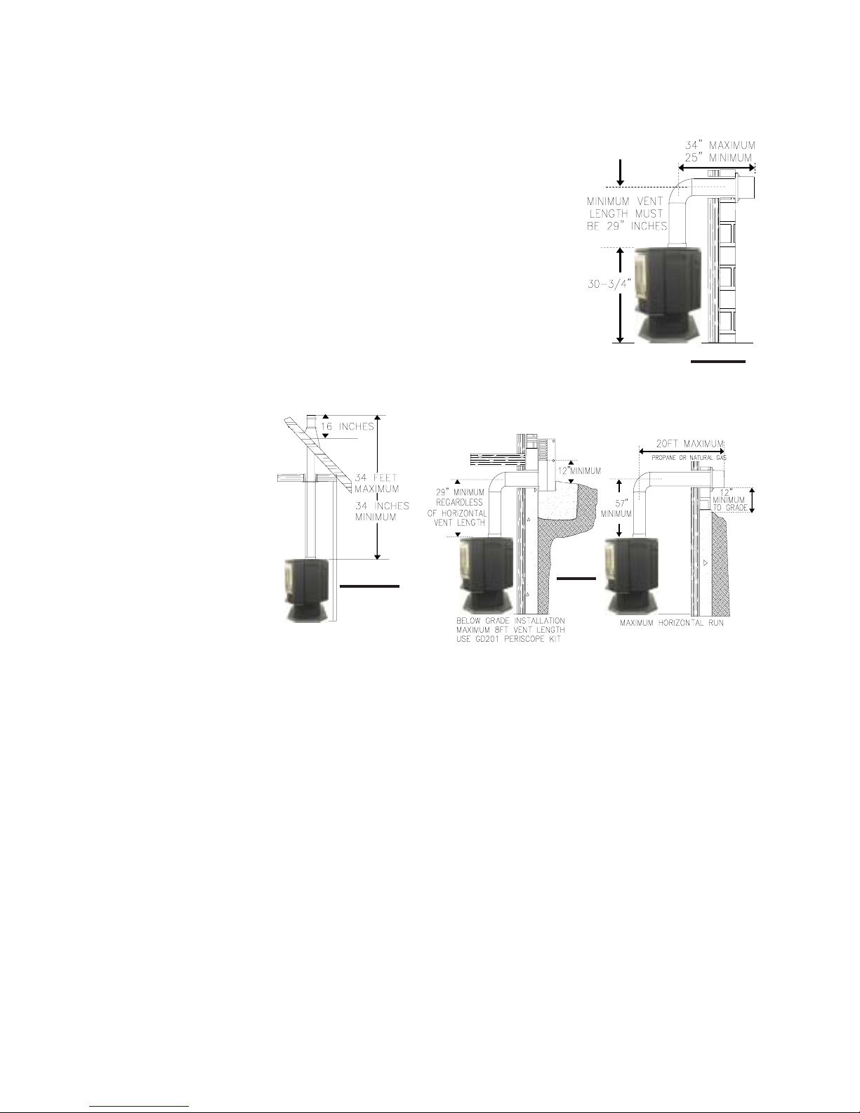
When terminating vertically, the
minimum vertical rise is 34 inches
above the stove and the maximum
vertical rise is 34 feet. FIGURE 4.
Deviation from the minimum vertical vent length can create difficulty in burner start-up and/or
carboning.
Use an adjustable pipe as the final length of rigid piping
to the stove for ease of installation.
We recommend that exhaust vents that pass through
unheated spaces be wrapped in a protective sleeve to
minimize condensation and re verse flow symptoms . See
Tr oub le Shooting for details.
FIGURE 4
For optimum flame appearance and stove performance, keep the vent
length and number of elbows to a minimum. On
extreme vent configurations, allow several minutes (5-15) for the flame to
stabilize after lighting. The
air terminal must remain
unobstructed at all times.
Examine the air terminal at
least once a year to verify
that it is unobstructed and
undamaged.
The maximum horizontal run is 34 inches with a 90o elbow
located 29" above the stove. FIGURE 5.
The maximum horizontal run with a 57 inch vertical rise
immediately above the stove is 20 feet FIGURES 6.
FIGS 6
HORIZONTAL RUN NOT TO EXCEED VERTICAL RISE
IF VERTICAL RISES GREATER THAN 57 INCHES
ARE NECESSARY, THE INCREASED RISE MUST
BE DEDUCTED FROM THE HORIZONTAL RUN.
FIGURE 5
A terminal shall not terminate directly above a sidewalk or paved driveway which is located betweeen
two single family dwellings and serves both dwellings. Local codes or regulations may require different clearances.
Do not allow the inside liner to bunch up on horizontal or vertical runs and elbows. Keep it pulled
tight. a 1-1/4" air gap all around between the inner
liner and outer stove pipe is required for safe operation. Use a firestop when penetrating interior
walls, floor or ceiling.
All horizontal runs must have a minimum ¼ inch
rise per foot.
WS-415-098 / 04.11.00

AIR AIR
AIR
AIR AIR
FIGURE 7
A
TERMINTERMIN
TERMIN
TERMINTERMIN
INSTALLATIONS
AL INSTAL INST
AL INST
AL INSTAL INST
CANADIAN U.S.A.
12 INCHES
12 INCHES
ALLAALLA
ALLA
ALLAALLA
TIONS:TIONS:
TIONS:
TIONS:TIONS:
Clearance above grade, veranda porch, deck or balcony .
7
B
C
D
E
F
12 INCHES
12 INCHES*
18 INCHES**
12 INCHES**
0 INCHES
0 INCHES***
9 INCHES
12 INCHES*
18 INCHES**
12 INCHES**
0 INCHES
0 INCHES***
G
2 INCHES***
H
I
J
K
L
M
N
O
**
* Recommended to prevent condensation on windows and thermal breakage
**
****
** It is recommended to use a heat shield and to maximize the distance to vinyl clad sof fits.
****
******
*** The periscope GD-201 requires a minimum 18 inches clearance from an inside corner.
******
********
**** This is a recommended distance. For additional requirements check local codes.
********
††
† Three feet above if within 10 feet horizontally.
††
‡‡
‡ A vent shall not terminate directly above a sidewalk or paved driveway that is located between two single family
‡‡
††††
† † Permitted only if the veranda, porch, or deck is fully open on a minimum of two sides beneath the floor.
††††
†*†*
†* Recommenced to prevent recirculation of exhaust products. For additional requirements check local codes.
†*†*
3 FEET
6 FEET
12 INCHES
6 FEET
7 FEET‡
12 INCHES††
16 INCHES
2 FEET†*
dwellings and serves both dwellings.
2 INCHES***
3 FEET****
3 FEET****
9 INCHES
3 FEET†
7 FEET****
12 INCHES****
16 INCHES
2 FEET†*
Clearance to windows or doors that open.
Clearance to permanently closed windows.
Vertical clearance to ventilated sof fit located above the terminal within
a horizontal distance of 2 feet from the centerline of the terminal.
Clearance to unventilated soffit.
Clearance to an outside corner wall.
Clearance to an inside non-combustible corner wall or protruding
non-combustible obstructions (chimney , etc.).
Clearance to an inside combustible corner wall or protruding com-
bustible obstructions ( vent chase, etc.).
Clearance to each side of the centerline extended above the meter
/ regulator assembly .
Clearance to a service regulator vent outlet.
Clearance to a non-mechanical air supply inlet to the building or a
combustion air inlet to any other appliance.
Clearance to a mechanical air supply inlet.
Clearance above a paved sidewalk or paved driveway located on
public property unless fitted with a heat shield kit GD-301.
Clearance under a veranda, porch, deck or balcony .
Clearance above the roof.
Clearance from an adjacent wall including neighbouring buildings.
WS-415-098 / 04.11.00
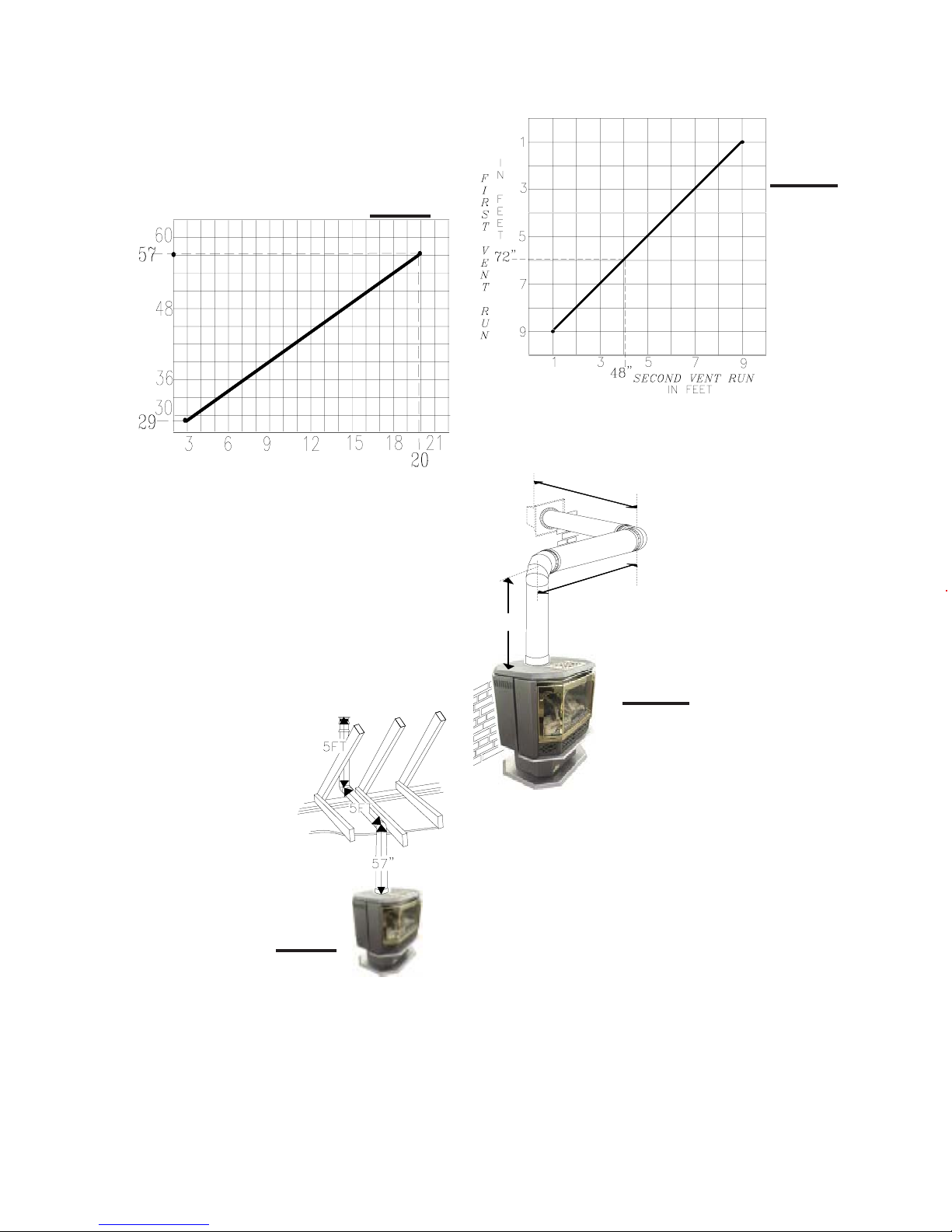
Use the chart on this page to calculate horizontal runs for
8
vertical rises between 29 and 57 inches. FIGURE 8.
When calculating maximum run lengths, include 10 feet for
each 90° elbow or 5 feet for each 45° elbow.
(DO NOT INCLUDE THE FIRST ELBOW DIRECTLY OFF
THE UNIT.)
FIGURE 8
REQUIRED
VERTICAL
RISE FROM
FIREPLACE
TO FIRST
ELBOW IN
INCHES
CALCULATED HORIZONTAL VENT RUN IN FEET
SPECIAL INSTALLATION EXAMPLE
When a horizontal run is introduced, even though the terminal may be vertical, the installation must be considered
HORIZONT AL.
A through the roof installation requires a total 5 foot rise.
FIGURE 9. The location of the fireplace dictates a horizontal
run of 5 feet. What is the required vertical rise to the centre
of the initial 90° elbow?
The total run is: 5 ft. (through the roof vertical rise)
10 ft. (90° elbow)
5 ft. (horizontal run)
20 ft. (total run)
Using the chart, will determine
that a 57 inch minimum vertical
rise immediately off the unit is
required for satisfactory venting
conditions.
OFFSET INSTALLATION EXAMPLE
FIGURE 10
If a first run of 72 inches is
required, using the "First Vent
Run" on the chart shows that
a maximum second run of
48 inches is allowable.
IF NECESSARY, THE
FIRST RUN AND THE SECOND RUN MAY BE REVERSED.
FIGURE 11
57"
48"
s
e
c
o
n
d
r
u
first run
72"
n
ALTHOUGH THE IMMEDIATE VERTICAL
RUN MAY BE GREATER THAN 57
INCHES, THE MAXIMUM COMBINATION OF HORIZONTAL AND VERTICAL
RUNS, BEYOND THE 57 INCHES,
MUST NOT EXCEED 20 FEET.
FIGURE 9
WS-415-098 / 04.11.00
WALL AND CEILING PROTECTION
FOR SAFE AND PROPER OPERA TION OF THE STOVE, FOLLOW THE VENTING INSTRUCTIONS EXACTL Y .
9
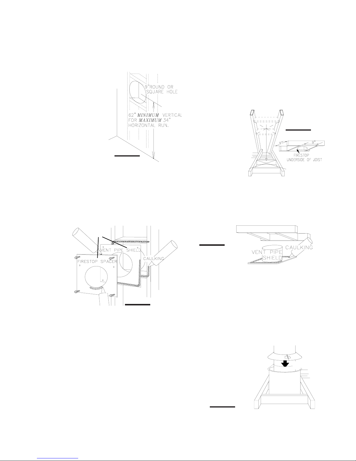
HORIZONTAL INST ALLATION: This application oc-
curs when venting through
an exterior wall. FIGURES
5, 6, & 13. Having determined the air terminal location, cut and frame a hole in
an exterior wall with a minimum square or round opening of 9". (As an alternative
to framing, a vent pipe
shield may be installed, ensuring a 1" clearance to
combustibles. See
Figure 12.)
THE STOVE PIPE MUST RISE ¼" PER FOOT OF RUN.
1. Mark and cut the vent pipe shield to the determined
depth of the combustible wall. Apply a bead of caulking (not
supplied) to the framework or to the shield plate (in the
case of a finished wall) and secure the shield through the
opening to the interior wall. The final location of the vent
pipe shield should maintain the required clearance to the
7" vent pipe. Do not fill this cavity with any type of material.
FIGURE 12
OR
VERTICAL INSTALLATION: This application occurs when
venting through a roof. FIGURE 4. Installation kits for various roof pitches are available from your Napoleon dealer.
See Accessories to order the specific kit required.
1. Determine the air terminal location and move
the stove into position.
Cut and frame 9 inch
openings in the ceiling
and the roof to provide the
minimum 1 inch clearance between the stove
pipe and any combustible
material. Try to center the
exhaust pipe location
midway between two joist
to prevent having to cut
them. Use a plumb bob
to line up the center of the
openings.
Do not fill this space with any type of material.
A vent pipe shield will prevent any materials such as insulation, from filling up the 1" air space around the pipe.
FIGURE 16. Nail headers between the joist for extra support.
FIGURE 15
FIGURE 14
FIGURE 13
Apply a bead of caulking all around and place a firestop
spacer over the vent shield to restrict cold air from being
drawn into the room or around the stove. Ensure that both
spacer and shield maintain the required clearance to combustibles. Once the vent pipe is installed in its final position, apply sealant between the pipe and the firestop spacer.
2. Apply a bead of caulking (not supplied) to the framework or to the Wolf Steel vent pipe shield plate or equivalent
(in the case of a finished ceiling), and secure over the opening in the ceiling. FIGURE 15. A firestop must be placed on
the bottom of each framed opening in a roof or ceiling that
the venting system passes through. FIGURE 14. Apply a
bead of caulking all around and place a firestop spacer
over the vent shield to restrict cold air from being drawn into
the room or around the stove. Ensure that both spacer and
shield maintain the required clearance to combustibles.
Once the vent pipe is installed in its final position, apply
sealant between the pipe and the firestop spacer.
3. In the attic, after the pipe
has been installed, slide the
vent pipe collar down to cover up
the open end of the shield and
tighten. This will prevent any materials, such as insulation, from
filling up the 1" air space around
the pipe.
FIGURE 16
VENT PIPE
SHIELD
VENT
PIPE
COLLAR
WS-415-098 / 04.11.00
 Loading...