

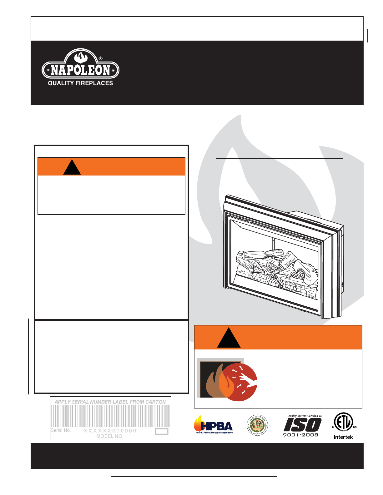
Napoleon GDI-44N, GDI-44P Installation And Operating Instructions Manual
INSTALLER: LEAVE THIS MANUAL WITH THE APPLIANCE.
CONSUMER: RETAIN THIS MANUAL FOR FUTURE REFERENCE.
NEVER LEAVE CHILDREN OR OTHER AT RISK INDIVIDUALS ALONE WITH THE APPLIANCE
INSTALLATION AND
OPERATING INSTRUCTIONS
CERTIFIED UNDER CANADIAN AND AMERICAN NATIONAL STANDARDS: CSA 2.33, ANSI Z21.50 FOR VENTED GAS FIREPLACE.
1
CERTIFIED FOR CANADA AND UNITED STATES USING ANSI/CSA METHODS.
SAFETY INFORMATION
CERTIFIED FOR CANADA AND UNITED STATES USING ANSI/CSA METHODS.
If the information in these instructions
are not followed exactly, a fi re or
explosion may result causing property
damage, personal injury or loss of life.
- Do not store or use gasoline or other fl ammable
vapors and liquids in the vicinity of this or any
other appliance.
- WHAT TO DO IF YOU SMELL GAS:
• Do not try to light any appliance.
• Do not touch any electrical switch; do not use
any phone in your building.
• Immediately call your gas supplier from a
neighbour’s phone. Follow the gas supplier’s
instructions.
• If you cannot reach your gas supplier, call the
fi re department.
- Installation and service must be performed by a
qualifi ed installer, service agency or the supplier.
This appliance may be installed in an aftermarket,
permanently located, manufactured home (USA
only) or mobile home, where not prohibited by
local codes.
This appliance is only for use with the type of gas
indicated on the rating plate. This appliance is
not convertible for use with other gases, unless a
certifi ed kit is used.
!
WARNING
GDI-44N
NATURAL GAS
GDI-44P
PROPANE
!
WARNING
HOT GLASS WILL CAUSE
BURNS.
DO NOT TOUCH GLASS UNTIL
COOLED.
NEVER ALLOW CHILDREN TO
TOUCH GLASS.
Wolf Steel Ltd., 24 Napoleon Rd., Barrie, ON, L4M 0G8 Canada /
103 Miller Drive, Crittenden, Kentucky, USA, 41030
Phone (705)721-1212 • Fax (705)722-6031 • www.napoleonfi replaces.com • ask@napoleonproducts.com
$10.00
1.28C
W415-0734 / D / 02.03.12
2
1.0 INSTALLATION OVERVIEW 2
TABLE OF CONTENTS
2.0 INTRODUCTION 3
3.0 INSTALLATION 7
4.0 FINISHING 11
5.0 REPLACEMENT BLOWER INSTALLATION 15
6.0 OPERATION 16
7.0 ADJUSTMENTS 17
8.0 MAINTENANCE 19
9.0 REPLACEMENTS 21
10.0 TROUBLE SHOOTING 24
11.0 WARRANTY 26
12.0 SERVICE HISTORY 27
2.1 DIMENSIONS 4
2.2 GENERAL INSTRUCTIONS 5
2.3 GENERAL INFORMATION 6
2.4 RATING PLATE INFORMATION 6
3.1 LEVELLING THE APPLIANCE 7
3.2 CHIMNEY CONNECTION 8
3.3 GAS INSTALLATION 10
3.4 OPTIONAL ACCESSORY REQUIREMENTS 10
4.1 MINIMUM MANTEL CLEARANCE 11
4.2 DOOR REMOVAL AND INSTALLATION 12
4.3 LOG PLACEMENT 13
4.4 GLOWING EMBERS 13
4.5 ALUMINUM EXTRUSION TRIM KIT INSTALLATION 14
6.1 REAR BURNER CONTROL 16
7.1 VENT RESTRICTION 17
7.2 PILOT BURNER ADJUSTMENT 17
7.3 VENTURI ADJUSTMENT 18
7.4 FLAME CHARACTERISTICS 18
8.1 DOOR GLASS REPLACEMENT 20
8.2 CARE OF GLASS 20
8.3 CARE OF PLATED PARTS 20
NOTE: Changes, other than editorial, are denoted by a vertical line in the margin.
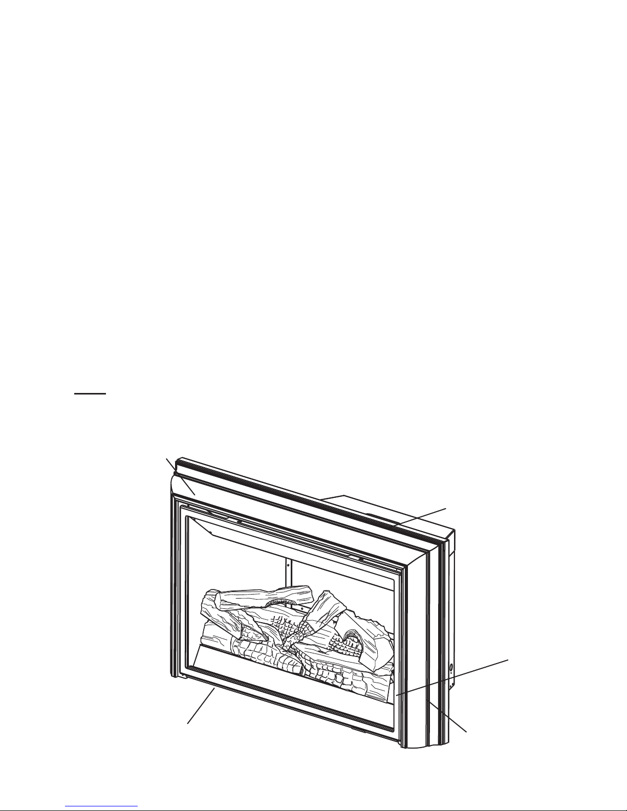
1.0 INSTALLATION OVERVIEW
Trim, see “ALUMINUM EXTRUSION TRIM
KIT INSTALLATION” section.
Venting, see “CHIMNEY
CONNECTION” section.
Logs, see “LOG
PLACEMENT”
section.
Door, see “DOOR REMOVAL
AND INSTALLATION” section.
W415-0734 / D / 02.03.12
Rating plate, see
“RATING PLATE
INFORMATION”
section.

2.0 INTRODUCTION
• THIS APPLIANCE IS HOT WHEN OPERATED AND CAN CAUSE SEVERE BURNS IF CONTACTED.
• ANY CHANGES TO THIS APPLIANCE OR IT’S CONTROLS CAN BE DANGEROUS AND IS PROHIBITED.
• Do not operate appliance before reading and understanding operating instructions. Failure to operate appliance
according to operating instructions could cause fi re or injury.
• Risk of fi re or asphyxiation do not operate appliance with fi xed glass removed.
• Do not connect 110 volts to the control valve.
• Risk of burns. The appliance should be turned off and cooled before servicing.
• Do not install damaged, incomplete or substitute components.
• Risk of cuts and abrasions. Wear protective gloves and safety glasses during installation. Sheet metal edges may be
sharp.
• Do not burn wood or other materials in this appliance.
• Children and adults should be alerted to the hazards of high surface temperature and should stay away to avoid burns or
clothing ignition.
• Young children should be carefully supervised when they are in the same room as the appliance.
young children and others may be susceptible to accidental contact burns. A physical barrier is recommended if there
are at risk individuals in the house. To restrict access to an appliance or stove, install an adjustable safety gate to keep
toddlers, young children and other at risk individuals out of the room and away from hot surfaces.
• Clothing or other fl ammable material should not be placed on or near the appliance.
• Due to high temperatures, the appliance should be located out of traffi c and away from furniture and draperies.
• Ensure you have incorporated adequate safety measure to protect infants/toddlers from touching hot surfaces.
• Even after the appliance is out, the glass and/or screen will remain hot for an extended period of time.
• Check with your local hearth specialty dealer for safety screens and hearth guards to protect children from hot surfaces.
These screens and guards must be fastened to the fl oor.
• Any safety screen or guard removed for servicing must be replaced prior to operating the appliance.
• The appliance is a vented gas-fi red appliance. Do not burn wood or other materials in the appliance.
• It is imperative that the control compartments, burners and circulating blower and its passageway in the appliance
and venting system are kept clean. The appliance and its venting system should be inspected before use and at least
annually by a qualifi ed service person. More frequent cleaning may be required due to excessive lint from carpeting,
bedding material, etc. The appliance area must be kept clear and free from combustible materials, gasoline and other
fl ammable vapors and liquids.
• Under no circumstances should this appliance be modifi ed.
• This appliance must not be connected to a chimney fl ue pipe serving a separate solid fuel burning appliance.
• Do not use this appliance if any part has been under water. Immediately call a qualifi ed service technician to inspect the
appliance and to replace any part of the control system and any gas control which has been under water.
• Do not operate the appliance with the glass door removed, cracked or broken. Replacement of the glass should be done
by a licensed or qualifi ed service person.
• Do not strike or slam shut the appliance glass door.
• When equipped with pressure relief doors, they must be kept closed while the appliance is operating to prevent exhaust
fumes containing carbon monoxide, from entering into the home. Temperatures of the exhaust escaping through these
openings can also cause the surrounding combustible materials to overheat and catch fi re.Only doors / optional fronts
certifi ed with the unit are to be installed on the appliance.
• Only doors / optional fronts certifi ed with the unit are to be installed on the appliance.
• Keep the packaging material out of reach of children and dispose of the material in a safe manner. As with all plastic
bags, these are not toys and should be kept away from children and infants.
• As with any combustion appliance, we recommend having your appliance regularly inspected and serviced as well as
having a Carbon Monoxide Detector installed in the same area to defend you and your family against Carbon Monoxide.
• Ensure clearances to combustibles are maintained when building a mantel or shelves above the appliance. Elevated
temperatures on the wall or in the air above the appliance can cause melting, discolouration or damage to decorations, a
T.V. or other electronic components.
• This appliance uses and requires a fast acting thermocouple. Replace only with a fast acting thermocouple supplied by
Wolf Steel Ltd.
!
WARNING
3
Toddlers,
3.1C
W415-0734 / D / 02.03.12
4
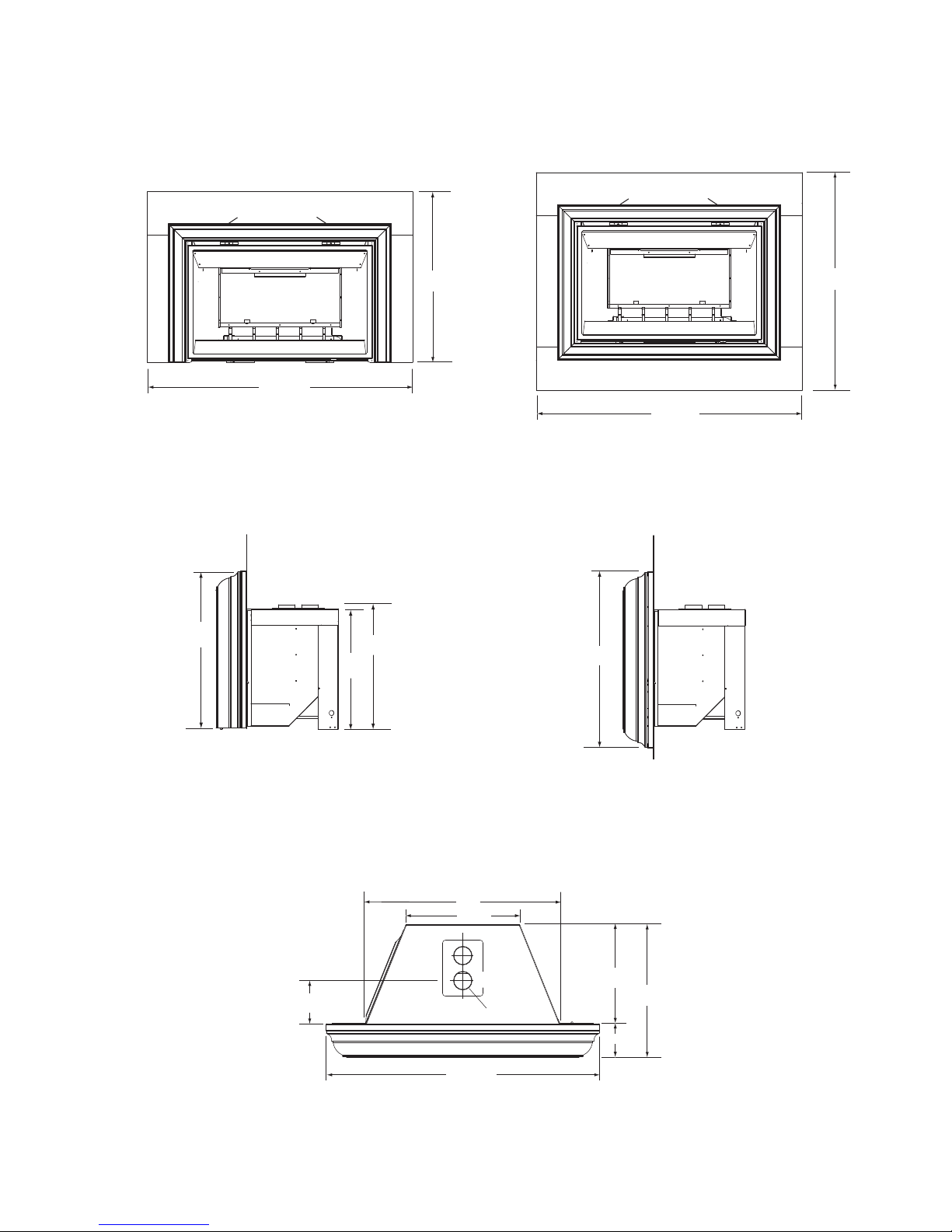
43 7/8"
18 ½"
32"
15 ½"
6 ½"
AIR
INLET
EXHAUST
3"ø
5 ¼"
20 ¾"
30 ½"
21"
22"
27 ¼"
52 1/8"
42 ¾"
ALUMINUM TRIM
52 1/8"
33 ½"
ALUMINUM TRIM
2.1 DIMENSIONS
3 SIDED BACKER PLATE - FRONT VIEW
3 SIDED BACKER PLATE - SIDE VIEW
4 SIDED BACKER PLATE - FRONT VIEW
4 SIDED BACKER PLATE - SIDE VIEW
W415-0734 / D / 02.03.12
TOP VIEW

2.2 GENERAL INSTRUCTIONS
A
ALWAYS LIGHT THE PILOT WHETHER FOR THE FIRST TIME OR IF THE GAS SUPPLY HAS RUN OUT,
WITH THE GLASS DOOR OPENED OR REMOVED.
PROVIDE ADEQUATE CLEARANCE FOR SERVICING AND OPERATING THE APPLIANCE.
NEVER OBSTRUCT THE FRONT OPENING OF THE APPLIANCE.
OBJECTS PLACED IN FRONT OF THE APPLIANCE MUST BE KEPT A MINIMUM OF 48” FROM THE
SURFACES AROUND AND ESPECIALLY ABOVE THE APPLIANCE CAN BECOME HOT. AVOID CONTACT
WHEN THE APPLIANCE IS OPERATING.
HIGH PRESSURE WILL DAMAGE VALVE. DISCONNECT GAS SUPPLY PIPING BEFORE PRESSURE TESTING GAS
LINE AT TEST PRESSURES ABOVE 1/2 PSIG. CLOSE THE MANUAL SHUT-OFF VALVE BEFORE PRESSURE
TESTING GAS LINE AT TEST PRESSURES EQUAL TO OR LESS THAN 1/2 PSIG.
USE ONLY WOLF STEEL APPROVED OPTIONAL ACCESSORIES AND REPLACEMENT PARTS WITH THIS APPLIANCE.
USING NON-LISTED ACCESSORIES (BLOWERS, DOORS, LOUVRES, TRIMS, GAS COMPONENTS, VENTING
COMPONENTS, ETC.) COULD RESULT IN A SAFETY HAZARD AND WILL VOID THE WARRANTY AND CERTIFICATION.
THIS GAS APPLIANCE SHOULD BE INSTALLED AND SERVICED BY A QUALIFIED INSTALLER to
conform with local codes. Installation practices vary from region to region and it is important to know the
specifi cs that apply to your area, for example in Massachusetts State:
• This product must be installed by a licensed plumber or gas fi tter when installed within the commonwealth
of Massachusetts.
• The appliance damper must be removed or welded in the open position prior to installation of a appliance
insert or gas log.
• The appliance off valve must be a “T” handle gas cock.
• The fl exible connector must not be longer than 36 inches.
• A Carbon Monoxide detector is required in all rooms containing gas fi red appliances.
• The appliance is not approved for installation in a bedroom or bathroom unless the unit is a direct vent
sealed combustion product.
The installation must conform with local codes or, in
absence of local codes, the National Gas and Propane
Installation Code CSA B149.1 in Canada, or the National
Fuel Gas Code, ANSI Z223.1 / NFPA 54 in the United
States. Suitable for mobile home installation if installed in
accordance with the current standard CAN/CSA Z240MH
Series, for gas equipped mobile homes, in Canada or
NSI Z223.1 and NFPA 54 in the United States.
!
WARNING
PROVIDE ADEQUA TE VENTILA TION.
FRONT FACE OF THE APPLIANCE.
FIRE RISK. EXPLOSION HAZARD.
www.ncertied.org
5
We suggest that our gas
hearth products be installed
and serviced by professionals
who are certied in the U.S.
by the National Fireplace
®
Institute
Specialists
(NFI) as NFI Gas
Some appliances have optional fans or blowers. If an optional fan or blower is installed, the junction box must
be electrically connected and grounded in accordance with local codes, use the current CSA C22.1 Canadian
Electrical Code in Canada or the ANSI/NFPA 70 National Electrical code in the United States.
4.12
W415-0734 / D / 02.03.12
6
HOME OME
UR AU CANADA OU AUX UR AU
NCENDIE POUR LES INSTALLATIONS ENDIE POUR LES INSTALLATIONS
S W.C. (NG) / 10 INCHES W.C.(LP)W.C. (NG) / 10 INCHES W.C
4.5" D'UNE COLONNE D'EAU (GN 4.5" D'UNE COLONNE D'EAU
)7" W.C. (NG) / 13" W.C. (LP)
MENTATION MAX :MENTATION MAX :
7" D'UNE COLONNE D'EA 7" D'UNE COLONNE D'E
DO NOT ADD ANY MATERIAL TO THNOT ADD ANY MATERIAL TO T
WITH THE APPLIANCE.WITH THE APPLIANCE.
:AVERTISSEM
N'AJOUTEZ PAS A COUTEZ PAS
THE APPLIANCE MUST BE VETHE APPLIANCE MUST BE V
SEE OWNERS INSTALLATISEE OWNERS INSTALLAT
NTAKE SYSTE
WARNINWA
ONLYON
2.3 GENERAL INFORMATION
FOR YOUR SATISFACTION, THIS APPLIANCE HAS BEEN TEST-FIRED TO ASSURE ITS
OPERA TION AND QUALITY!
GDI44
NG LP
Altitude (FT) 0-4,500 0-4,500
Max. Input (BTU/HR) 40,000 40,000
Max. Output (BTU/HR) 27,600 27,600
Effi ciency (w/the fan on) 69% 69%
Min. Inlet Gas Supply
Pressure
Max. Inlet Gas Supply
Pressure
Manifold Pressure (Under
Flow Conditions)
When the appliance is installed at elevations above 4,500ft, and in the absence of specifi c recommendations
from the local authority having jurisdiction, the certifi ed high altitude input rating shall be reduced at the rate of
4% for each additional 1,000ft.
Expansion / contraction noises during heating up and cooling down cycles are normal and to be expected.
In order to achieve maximum turn down rate, the rear burner must be turned off. See Operating Instructions in
the owner's manual for more information.
This appliance is not approved for closet or recessed installations. It is approved for bathroom, bedroom and
bed-sitting room installations and is suitable for mobile homes. The natural gas model is suitable for installation
in a mobile home that is permanently positioned on its site and fuelled with natural gas.
This appliance must be recessed into a vented noncombustible wood-burning fi replace (prefabricated or
masonry) only.
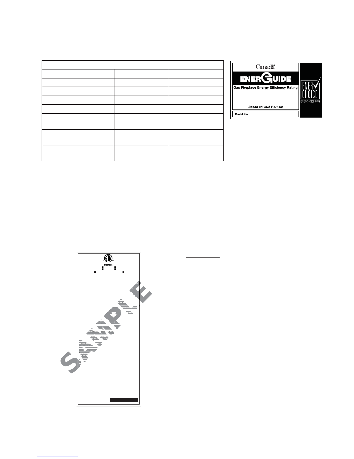
2.4 RATING PLATE INFORMATION
CERTIFIED UNDER: CSA 2.22b-2009, ANSI
Z21.50b-2009 VENTED GAS FIREPLACE.
9700539 (WSL) 4001657 (NGZ)
4001658 (NAC) 4001659 (WUSA)
GDI-44N / CDI-44N MODEL GDI-44P / CDI-44P
0 - 4500FT ALTITUDE/ELEVATION 0 - 4500FT
40,000 BTU/h INPUT / ALIMENTATION 40,000 BTU/h
13,000 BTU/h REDUCED INPUT / ALIMENTATION REDUITE 10,000 BTU/h
THIS FIREPLACE USES AND REQUIRES A FAST ACTING THERMOCOUPLE. REPLACE
ONLY WITH A FAST ACTING THERMOCOUPLE SUPPLIED BY WOLF STEEL LTD.
APPROVED FOR BEDROOM, BATHROOM & BEDSITTING ROOM INSTALLATION. SUITABLE
FOR MOBILE HOME INSTALLATION IF INSTALLED IN ACCORDANCE WITH THE CURRENT
STANDARD CAN/CSA Z240MH SERIES GAS EQUIPPED MOBILE HOMES, IN CANADA OR IN
THE UNITED STATES THE MANUFACTURED HOME CONSTRUCTION AND SAFETY
STANDARD, TITLE 24 CFR, PART 3280. WHEN THIS US STANDARD IS NOT APPLICABLE
USE THE STANDARD FOR FIRE SAFETY CRITERIA FOR MANUFACTURED HOME
INSTALLATIONS, SITES AND COMMUNITIES, ANSI / NFPA 501A.
HOMOLOGUE POUR INSTALLATION DANS UNE CHAMBRE A COUCHER, UNE SALLE DE
BAIN ET UN STUDIO. APPROPRIE POUR INSTALLATION DANS UNE MAISON MOBILE SI
SON INSTALLATION CONFORME AUX EXIGENCES DE LA NORME CAN/CSA Z240MH
SERIE DE MAISONS MOBILES EQUIPEES AU GAZ, EN VIGUEUR AU CANADA OU AUX
ETATS-UNIS DE LA NORME DE SECURITE ET DE CONSTRUCTION DE MAISONS
MANUFACTUREES, TITRE 24 CFR, SECTION 3280. DANS LE CAS OU CETTE NORME
D'ETATS-UNIS NE PEUT ETRE APPLIQUEE, SE REFERER A LA NORME RELATIVE AU
CRITERE DE MESURES DE SECURITE CONTRE L'INCENDIE POUR LES INSTALLATIONS
DANS LES MAISONS MANUFACTURES, LES SITES ET LES COMMUNAUTES, ANSI/NFPA
501A.
MINIMUM AND MAXIMUM VERTICAL VENT LENGTHS ARE 7 FEET AND 40 FEET
RESPECTIVELY. LES LONGUEURS VERTICALES MINIMALES ET MAXIMALES SONT 7
PIEDS ET 40 PIEDS RESPECTIVEMENT.
MANIFOLD PRESSURE: 3.5 INCHES W.C. (NG) / 10 INCHES W.C.(LP)
PRESSION AU COLLECTEUR : 3.5" D'UNE COLONNE D'EAU(GN) / 10" D'UNE COLONNE
D'EAU (P)
MIN SUPPLY PRESSURE: 4.5" W.C.(NG) / 11" W.C. (LP)
PRESSION D'ALIMENTATION MIN : 4.5" D'UNE COLONNE D'EAU (GN) / 11" D'UNE
COLONNE D'EAU (P)
MAX. SUPPLY PRESSURE: 7" W.C. (NG) / 13" W.C. (LP)
PRESSION D'ALIMENTATION MAX : 7" D'UNE COLONNE D'EAU (GN) / 13" D'UNE
COLONNE D'EAU (P)
FOR USE WITH GLASS DOORS CERTIFIED WITH THIS UNIT ONLY.
UTILISER AVEC LES PORTES VITREES HOMOLOGUEES SEULEMENT AVEC CETTE
UNITE.
WARNING: DO NOT ADD ANY MATERIAL TO THE APPLIANCE, WHICH WILL COME IN
CONTACT WITH THE FLAMES, OTHER THAN THAT SUPPLIED BY THE MANUFACTURER
WITH THE APPLIANCE.
AVERTISSEMENT
AVERTISSEMENT : N'AJOUTEZ PAS A CET APPAREIL AUCUN MATERIAU DEVANT
ENTRER EN CONTACT AVEC LES FLAMMES AUTRE QUE CELUI QUI EST FOURNI AVEC
CET APPAREIL P AR LE FABRICANT.
ELECTRICAL RATING / CLASS.: 115V 1.5AMP 60HZ
THE APPLIANCE MUST BE VENTED USING THE APPROPRIATE WOLF STEEL VENT KITS.
SEE OWNERS INSTALLATION MANUAL FOR VENTING SPECIFICS. PROPER
REINSTALLATION AND RESEALING IS NECESSARY AFTER SERVICING THE VENTAIR
INTAKE SYSTEM.
INTAKE SYSTEM.
L'APPAREIL DOIT EVACUER SES GAZ EN UTILISANT L'ENSEMBLE D'EVACUATION
PROPRE A WOLF STEEL. REFERER AU MANUEL D'INSTALLATION DE PROPRIETAIRE
POUR L'EVACUATION PRECISE. IL EST IMPORTANT DE BIEN REINSTALLER ET
RESCELLER L'EVENT APRES AVOIR ASSURE LE MAINTIEN DU SYSTEME DE PRISE D'AIR.
WARNING: FOR INSTALLATION INTO A VENTED NON-COMBUSTIBLE FIREPLACE
ONLY. THE MINIMUM FIREPLACE SIZE IS: HEIGHT 21”, DEPTH 16”, WIDTH 32”. THE
MINIMUM INSIDE FLUE SIZE IS 7”. THE MINIMUM DISTANCE, FROM THE BOTTOM OF A
COMBUSTIBLE MANTLE PROJECTING A MAXIMUM 3” FROM THE WALL TO THE TOP OF
THE STANDARD TRIM IS 12”. SEE OWNERS MANUAL FOR GREATER EXTENSIONS.
A HEARTH MUST PROTRUDE A MINIMUM OF 12” FROM THE UNIT.
ATTENTION : POUR INSTALLATION DANS UN FOYER VENTILE EN MACONNERIE.
LES DIMENSIONS MINIMUMS SONT: HAUTEUR 21”, PROFONDEUR 16”, LARGEUR 32”. LE
DIAMETRE INTERIEUR MINIMUM DE CONDUIT D’EVACUATION EST DE 7”.
LA DISTANCE MINIMALE, DU BAS DU MANTEAU COMBUSTIBLE FORMANT UNE
PROJECTION MAXIMALE DE 3” DU MUR AU DESSUS DE LA GARNITURE NORMALE EST
12”. REFERER AU MANUEL D’INSTALLATION POUR DES EXTENSIONS PLUS GRANDES.
UNE DALLE DE PROTECTION INCOMBUSTIBLE DOIT SE PROLONGER D’AU MOINS 12" DE
L’UNITÉ.
7" W.C. (NG) / 13" W.C. (LP
NOT FOR USE WITH SOLID FUEL / UN COMBUSTIBLE
SOLIDE NE DOIT PAS ETRE UTILSE A VEC CET APPAREIL
24 NAPOLEON ROAD, BARRIE, ON, L4M 0G8 CANADA
SERIAL NUMBER
NO. DE SERIE
4.5" Water Column 11" Water Column
7" Water Column 13" Water Column
3.5" Water Column 10" Water Column
HOMOLOGUE SELON LES NORMES: CSA
2.22b-2009, ANSI Z21.50b-2009 FOYER
GAZ AVEC EVACUATION.
WOLF STEEL LTD.
GDI / CDI-44
W385-0252 / F
61.4%
GDI44
INSTALLER: It is your responsibility to check off
the appropriate box on the rating plate according
to the model, venting and gas type of the
appliance.
For rating plate location, see “INSTALLATION
OVERVIEW” section.
This illustration is for reference only. Refer to the
rating plate on the appliance for accurate information.
W415-0734 / D / 02.03.12

3.0 INSTALLATION
RISK OF FIRE, MAINTAIN SPECIFIED AIR SPACE CLEARANCES TO VENT PIPE AND APPLIANCE.
Clean out ashes from the inside of the wood-burning appliance. Make sure that the chimney and wood-burning
appliance are in a clean and sound condition and constructed of non-combustible materials. If necessary have
any repair work done by a qualifi ed person before installing the insert. Remove the existing appliance damper
or lock into an open position.
Using screws, attach the appliance warning tag
to the inside of the fi rebox of the appliance into
which the insert is being installed.
The sheet-metal parts of the appliance, in which
the gas appliance insert is to be installed, must
not be cut.
If the wood-burning factory-built appliance has
no gas access hole(s) provided, an access hole of 1½ inch or less may be drilled through the lower sides or
bottom of the appliance in a proper workman like manner. This access hole must be plugged with non-combustible insulation after the gas supply line has been installed.
!
WARNING
WARNING: THIS FIREPLACE HAS BEEN CONVERTED FOR USE WITH A GAS FIREPLACE
INSERT ONLY AND CANNOT BE USED FOR BURNING WOOD OR SOLID FUELS UNLESS ALL ORIGINAL
PARTS HAVE BEEN REPLACED AND THE FIREPLACE IS RE-APPROVED BY THE AUTHORITY HAVING
JURISDICTION.
ATTENTION: CE FOYER A ETE CONVERTI AFIN D’ETRE UTILISE SEULEMENT
COMME FOYER ENCASTRE AU GAZ ET NE PEUT ETRE UTILSE POUR BRULER DU BOIS OU
TOUT AUTRE COMBUSTIBLE SOLIDE, SANS QUE TOUTES LES PIECES ORIGINALES AIENT
ETE REMPLACEES ET QUE LE FOYER SOIT APPROUVE DE NOUVEAU PAR LES AUTORITES
AYANT JURIDICTION.
ADVERTENCIA: ESTA CHIMENEA SE REMODELÓ PARA USARSE SOLO CON UNA
INSERCIÓN DE CHIMENEA A GAS Y NO PUEDE USARSE PARA QUEMAR MADERA NI COMBUSTIBLES
SÓLIDOS, A MENOS QUE SE HAYAN REEMPLAZADO TODAS LAS PIEZAS ORIGINALES, Y LA AUTORIDAD JURISDICCIONAL LA HAYA VUELTO A APROBAR.
7
W385-0199_B
Ensure that existing chimney cleanouts fi t properly .
The refractory, glass doors, screen rails, screen mesh and log grates may be removed from the existing appli-
ance before installing the gas appliance insert.
Smoke shelves, shields and baffl es may be removed if attached by mechanical fasteners.
The ventilation openings in the existing appliance may be obstructed by the backer plates, aluminium trim etc.
but these parts are not to be applied so as to have an airtight seal.
3.1 LEVELLING THE APPLIANCE
Move the appliance close to its fi nal position. This appliance is equipped with levelling screws located on the
base. Level using the levelling screws. Levelling the appliance will eliminate rocking or excessive noise when
the fan is in operation. Once the appliance is level, move it partially into place to allow for all connections to be
made. It is not practical to level the appliance once it has been installed. Determine the required depth prior to
installing the appliance and adjust the levelling screws accordingly.
68.4A
67.2
W415-0734 / D / 02.03.12
8
3.2 CHIMNEY CONNECTION
Chimney installation must conform to both national and local code requirements. The chimney must be lined
with one 2" or 3" diameter liner for intake and one 3" diameter liner for exhaust. The minimum and maximum
vent lengths are 10 and 35 feet respectively. Recommended Napoleon® kits come in 3 lengths:
1-2" & 1-3" DOUBLE PLY ALUMINUM LINER-INLET AND EXHAUST &
2-3" TO 2" REDUCER:
GDI-2320KT VENT KIT 20FT
GDI-2325KT VENT KIT 25FT
GDI-2335KT VENT KIT 35FT
2-3" DOUBLE PLY ALUMINUM LINER-INLET AND EXHAUST:
GDI-320KT VENT KIT 20FT
GDI-325KT VENT KIT 25 FT
GDI-335KT VENT KIT 35 FT
While the liners must be continuous from the appliance to the chimney cap, to achieve the needed length, they
may be coupled, using an aluminium coupler, provided installation is sealed & secured.
We recommend that exhaust vents that pass through unheated spaces, such as a garage or attic, be
wrapped in a protective sleeve to minimize condensation and reverse fl ow symptoms.
This appliance is approved for use with a 2" liner for air intake and a 3" liner for exhaust. For best
performance, however, it is recommended to use two 3" liners.
If a 2" liner is used for the intake, it is necessary to adjust the primary air shutter. See "Air Shutter
Settings".
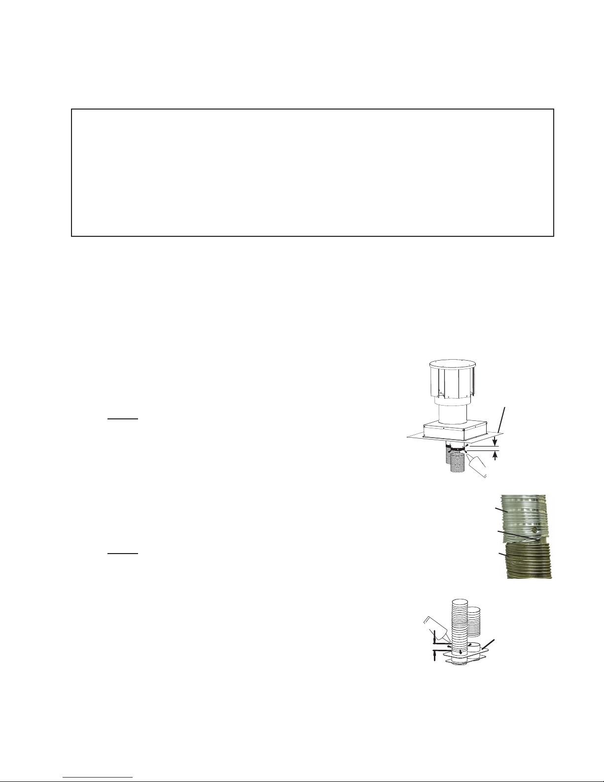
A. OUTSIDE: Slip the one end of a liner a minimum of 2" over the
collar of the air terminal. Secure using 3 screws. Then seal the
joint and screw heads with high temperature sealant. Repeat
with the other liner to the exhaust collar of the terminal.
NOTE: Connect the supplied 3' of stainless steel fl ex liner
to the exhaust liner (already attached to the terminal)
using the coupler (also supplied). Secure and seal before
dropping down the chimney.
EXHAUST
B. Gently stretch the liners to the required lengths and appliance
into the chimney. Place the terminal onto the top of the chimney
cap and fi t the fl ashing plate to suit. Make weather tight by sealing with
caulking (not supplied) and fasten to the chimney with screws and plugs
(not supplied).
C. NOTE: If there is not enough ceiling height between the fi replace
and the appliance to allow the fl ex liner connection on the top of
the appliance to be made, see "D". If there is enough ceiling height,
connect the 3" stainless steel fl ex liner to the exhaust collar closest to the
top front on the appliance. Connect the intake fl ex liner to
the remaining rear collar. Secure and seal.
HI-TEMP
SEALANT
2" OVERLAP
INTAKE
ALUMINUM
FLEX LINER
COUPLER
STAINLESS
STEEL
FLEX LINER
FLASHING
PLATE
2"
OVERLAP
SEALANT
HI-TEMP
VENT
CONNECTION
ASSEMBLY
W415-0734 / D / 02.03.12
9
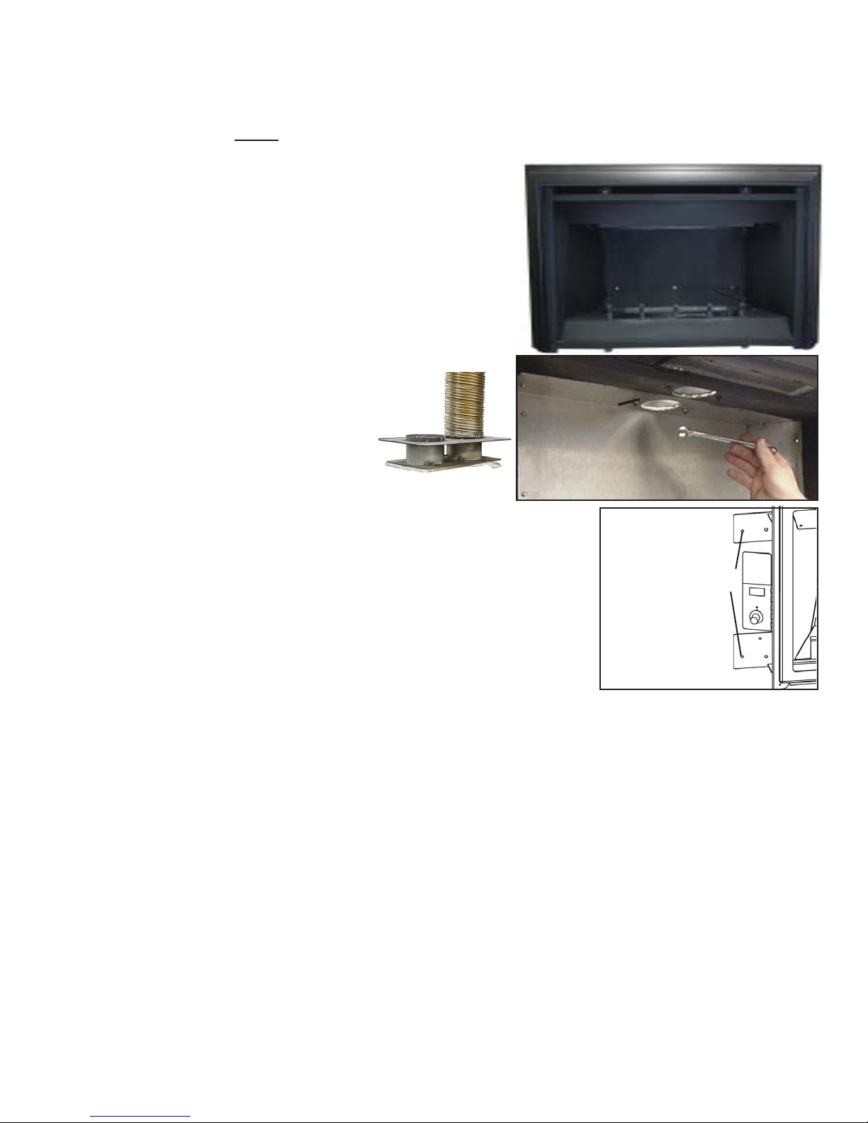
D. Both the log support and the back wall must be removed in order to gain access to the vent connection
assembly. Both the back wall and log support are detached by removing the 12 perimeter screws of
the back wall and the 3 screws located at the back of the log support. Remove the vent connection
assembly. NOTE: The vent connection assembly collars are not specifi c until the stainless steel
fl ex liner has been attached to one side. This now designates the side as exhaust. The exhaust
collar must be positioned closest to the front
opening of the appliance. Secure and seal the fl ex
liners.
E. To reinstall the vent connection assembly, reach
in through the appliance and manoeuvre the vent
connection assembly through the opening in the fi rebox
top. Take care not to damage the gasket. Secure the
assembly using the four studs and ¼-20 hex nuts.
F. Reinstall the back wall, followed by the log support,
using the perimeter screws
removed in "D". The appliance
may now bepushed into its fi nal
position inside the wood burning
fi replace.Secure the appliance
to the fi replace using perforated
strapping attached to the two
securing holes on either side
of the appliance as shown. We
VENT CONNECTION
ASSEMBLY
recommend that the trim be installed before the appliance is placed
into its fi nal position.
BACK WALL
LOG SUPPORT
VENT
CONNECTION
ASSEMBLY
SECURING
HOLES
W415-0734 / D / 02.03.12

10
3.3 GAS INSTALLATION
RISK OF FIRE, EXPLOSION OR ASPHYXIATION. ENSURE THERE ARE NO IGNITION SOURCES SUCH AS
SUPPORT GAS CONTROL WHEN ATTACHING GAS SUPPLY PIPE TO PREVENT DAMAGING GAS LINE.
ALWAYS LIGHT THE PILOT WHETHER FOR THE FIRST TIME OR IF THE GAS SUPPLY HAS RUN OUT
WITH THE GLASS DOOR OPENED OR REMOVED. PURGING OF THE GAS SUPPLY LINE SHOULD BE
PERFORMED BY A QUALIFIED SERVICE TECHNICIAN. ASSURE THAT A CONTINUOUS GAS FLOW IS AT
THE BURNER BEFORE CLOSING THE DOOR. ENSURE ADEQUATE VENTILATION. FOR GAS AND
ELECTRICAL LOCATIONS, SEE “DIMENSION” SECTION.
ALL GAS CONNECTIONS MUST BE CONTAINED WITHIN THE APPLIANCE WHEN COMPLETE.
HIGH PRESSURE WILL DAMAGE VALVE. DISCONNECT GAS SUPPLY PIPING BEFORE TESTING GAS
VALVE SETTINGS HAVE BEEN FACTORY SET, DO NOT CHANGE.
Installation and servicing to be done by a qualifi ed installer.
A. Move the appliance into position and secure.
B. If equipped with a fl ex connector the appliance is designed to accept a 1/2” gas supply. Without the
connector it is designed to accept a 3/8” gas supply. The appliance is equipped with a manual shut off
valve to turn off the gas supply to the appliance.
C. Connect the gas supply in accordance to local codes. In the absence of local codes, install to the
current CAN/CSA-B149.1 Installation Code in Canada or to the current National Fuel Gas Code, ANSI
Z223.1 / NFPA 54 in the United States.
D. When fl exing any gas line, support the gas valve so that the lines are not bent or kinked.
E. The gas line fl ex-connector should be installed to provide suffi cient movement for shifting the burner
assembly on it’s side to aid with servicing components.
F. Check for gas leaks by brushing on a soap and water solution. Do not use open fl ame.
For ease of accessibility, an optional remote wall switch or millivolt thermostat may be installed in a convenient
location. Route 2-strand solid core millivolt wire from the gas appliance to the wall switch / millivolt thermostat.
The recommended maximum lead length depends on the wire size:
WIRE SIZE MAX. LENGTH
14gauge 100 feet
16gauge 60 feet
18gauge 40 feet
Do not connect either the wall switch, thermostat or gas valve to electricity (110 VOLTS).
!
WARNING
SPARKS OR OPEN FLAMES.
LINE AT TEST PRESSURES ABOVE 1/2 PSIG.
30.1A
3.4 OPTIONAL ACCESSORY REQUIREMENTS
A. This appliance may be used with a wall switch, wall mounted thermostat and/or a remote control.
B. Wiring for optional Napoleon® approved accessories should be done now to avoid reconstruction.
Follow instructions that come with those accessories.
W415-0734 / D / 02.03.12
4.0 FINISHING
The minimum fi replace opening size in which the appliance is to be installed is:
HEIGHT 21 inches WIDTH 32 inches DEPTH 16 inches
The minimum allowable chimney fl ue size is 7" round.
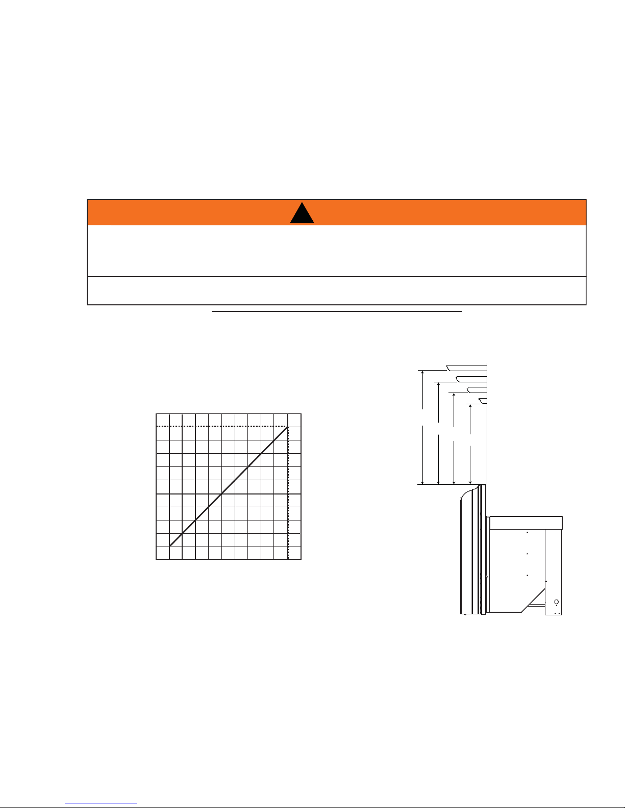
The minimum distance, from the bottom of a combustible mantle projecting 3" maximum from the wall to the
top of the aluminium trim, is 12". A hearth must protrude a minimum of 12" from the appliance.
4.1 MINIMUM MANTEL CLEARANCE
RISK OF FIRE, MAINTAIN ALL SPECIFIED AIR SPACE CLEARANCES TO COMBUSTIBLES. FAILURE
TO COMPLY WITH THESE INSTRUCTIONS MAY CAUSE A FIRE OR CAUSE THE APPLIANCE TO
OVERHEAT. ENSURE ALL CLEARANCES (I.E. BACK, SIDE, TOP, VENT, MANTEL, FRONT, ETC.) ARE
CLEARLY MAINTAINED.
WHEN USING PAINT OR LACQUER TO FINISH THE MANTEL, THE PAINT OR LACQUER MUST BE
HEAT RESISTANT TO PREVENT DISCOLOURATION.
This can vary according to the mantle depth. Use the graph to help evaluate the clearance needed.
!
WARNING
11
73.1
0
$
1
7
(
/
+
(
*
+
7
6” MANTEL
5”
4”
3”
15
15”
14”
13”
12”
14
,
13
12
0
35
4
6
MANTEL DEPTH
W415-0734 / D / 02.03.12
12
!
WARNING
RISK OF FIRE!
NEVER OBSTRUCT THE FRONT OPENING OF THE APPLIANCE.
THE FRONT OF THE APPLIANCE MUST BE FINISHED WITH ANY NON-COMBUSTIBLE MATERIALS
SUCH AS BRICK, MARBLE, GRANITE, ETC., PROVIDED THAT THESE MATERIALS DO NOT GO
BELOW THE SPECIFIED DIMENSION AS ILLUSTRATED.
DO NOT STRIKE, SLAM OR SCRATCH GLASS. DO NOT OPERATE APPLIANCE WITH GLASS
REMOVED, CRACKED, BROKEN OR SCRATCHED.
FACING AND/OR FINISHING MATERIAL MUST NEVER OVERHANG INTO THE APPLIANCE OPENING.
THE GLASS DOOR ASSEMBLY IS DESIGNED TO PIVOT FORWARD WHEN RELIEVING EXCESS
PRESSURE THAT MIGHT OCCUR. FINISHING OR OTHER MATERIALS MUST NOT BE LOCATED IN
THE OPENING SURROUNDING THE DOOR AS THIS WILL INTERFERE WITH THE DOORS ABILITY TO
RELIEVE THE PRESSURE.
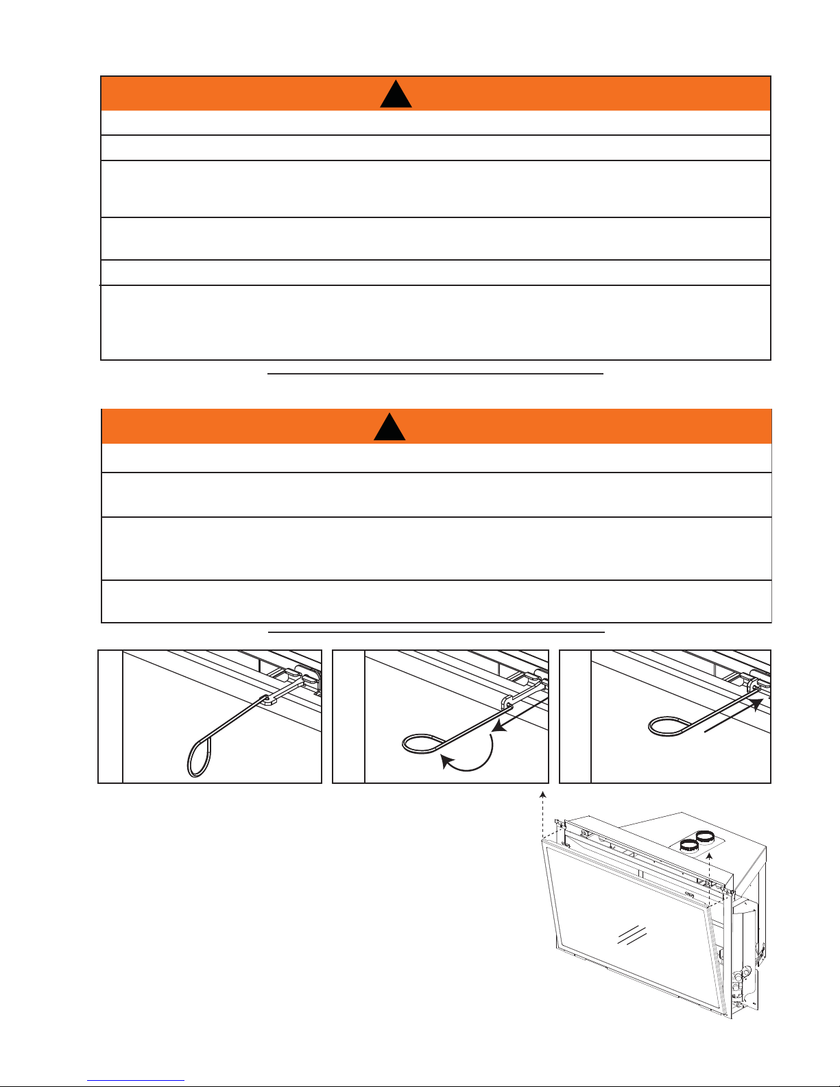
4.2 DOOR REMOVAL AND INSTALLATION
!
WARNING
GLASS MAY BE HOT, DO NOT TOUCH GLASS UNTIL COOLED.
72.6
THE DOOR LATCHES ARE PART OF A SAFETY SYSTEM AND MUST BE PROPERLY ENGAGED. DO
NOT OPERATE THE APPLIANCE WITH LATCHES DISENGAGED.
FACING AND/OR FINISHING MATERIALS MUST NOT INTERFERE WITH AIR FLOW THROUGH AIR
OPENINGS, LOUVRES OPENINGS, OPERATION OF LOUVRES OR DOORS OR ACCESS FOR
SERVICE. OBSERVE ALL CLEARANCES WHEN APPLYING COMBUSTIBLE MATERIALS.
BEFORE DOOR IS REMOVED TURN THE APPLIANCE OFF AND WAIT UNTIL APPLIANCE IS COOL TO
THE TOUCH. DOORS ARE HEAVY AND FRAGILE SO HANDLE WITH CARE.
75.1
A. Insert the tool supplied (which is
located behind the left side trim) into
spring loaded door latch.
B. Pull and turn the latch 90°.
C. Release the latch.
D. Tilt the top of the door forward until you
can grab the sides of the door. Lift up
and out of the bottom door retainer.
E. To install, reverse the order of these
instructions.
W415-0734 / D / 02.03.12
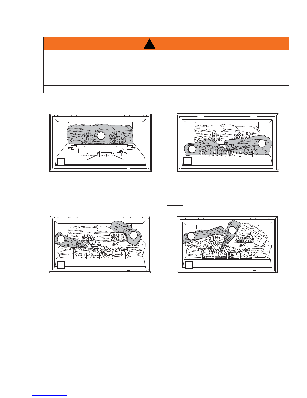
4.3 LOG PLACEMENT
FAILURE TO POSITION THE LOGS IN ACCORDANCE WITH THESE DIAGRAMS OR FAILURE TO USE
ONLY LOGS SPECIFICALLY APPROVED WITH THIS APPLIANCE MAY RESULT IN PROPERTY
LOGS MUST BE PLACED IN THEIR EXACT LOCATION IN THE APPLIANCE. DO NOT MODIFY THE
PROPER LOG POSITIONS, SINCE APPLIANCE MAY NOT FUNCTION PROPERLY AND DELAYED
THE LOGS ARE FRAGILE AND SHOULD BE HANDLED WITH CARE.
POSITIONING THE LOGS IMPROPERLY WILL CAUSE FLAME IMPINGEMENT AND CARBONING.
13
!
WARNING
DAMAGE OR PERSONAL INJURY.
IGNITION MAY OCCUR.
76.1A
1
2
3
LOCATING PIN
A
The rear log should be centred on the log support
and rest against the rear wall.
CENTRE
SUPPORT
LOCATING
PIN
4
6
C
Log (#6) has a leg that fi ts into an indentation on the
top of log (#3). Log (#4) rests in the indentations on
the tops of logs (#2) and (#1).
B
Log #3 rests against the far left grate post and onto
the locating pin on the centre support. Log #2 rests
against the far right grate post and over the locating
pin on the centre support and against the tip of log #3.
NOTE: Skewering log#2 onto the locating pin may
be necessary.
5
7
D
Logs (#5) and (#7) fi t onto the indentations of the
lower logs.
4.4 GLOWING EMBERS
Tear the embers into pieces and place along the front row of ports covering all of the burner area in front of
logs (#2 & #3). Care should be taken to shred the embers into thin, small irregular pieces as only the exposed
edges of the fi bre hairs will glow. The ember material will only glow when exposed to direct fl ame; how-
ever, care should be taken to not block the burner ports.
Blocked burner ports can cause an incorrect fl ame pattern, carbon deposits and delayed ignition. PHAZERTM
logs glow when exposed to direct fl ame. Use only certifi ed "glowing embers" and PHAZERTM logs available
from your Napoleon® dealer.
W415-0734 / D / 02.03.12
14
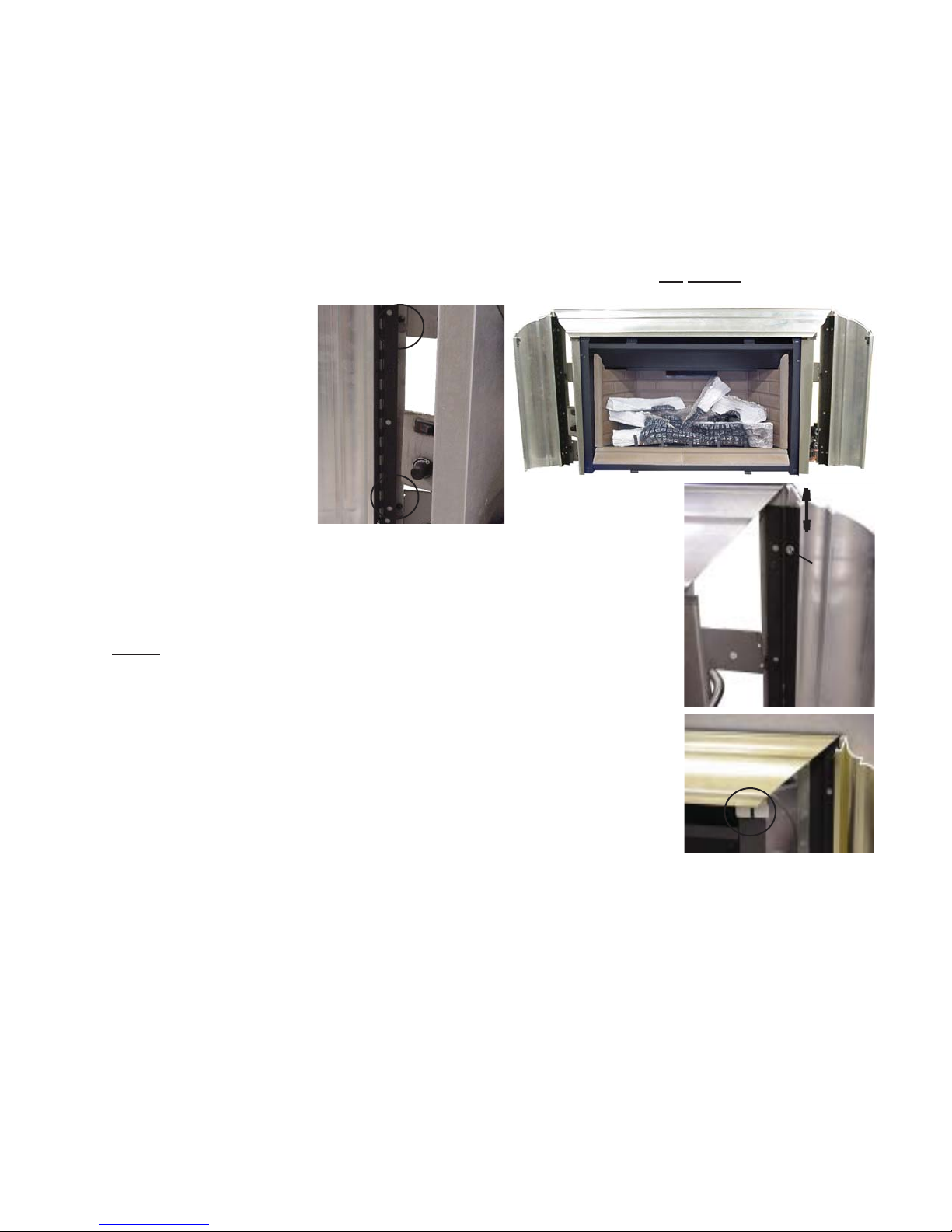
4.5 ALUMINUM EXTRUSION TRIM KIT INSTALLATION
In order to close off the fi replace opening or if the opening is larger than the 3- or 4-sided aluminium extrusion
trim kits, it is recommended to reduce the opening using a noncombustible material such as ceramic tile, marble, etc or the GDIBP3 or GDIBP4 backer plate kits. The GDIBP3 backer plate is able to fi t an opening of 52" x
33½". The GDIBP4 backer plate is able to fi t an opening of 52" x 42¾". The outside edge of the backer plate is
fi nished off with gold trim included in each kit. A GDIBP3D 3 sided deluxe backer plate complete with marquis
trim may also be used to complete the installation
installation instructions are included with each kit.
If this appliance is being installed into an existing wood burning, zero clearance fi replace, then be aware of this
precaution: Any circulation air opening may be covered (with material) but not sealed!
The appliance can be
equipped with either a 3- or
4-sided trim kit to fi nish off
the fi replace opening. Slide
the trim assembly over the
keyholes (2 per side) and
drop into place. If installing
the optional 3- or 4-sided
backer plate (GDIBP3 or
GDIBP4), it must be hung
prior to the trim kit installation
using the same keyholes.
. This kit is able to fi t an opening of 57" x 33½". Detailed
SLIDE TO
ADJUST
TO ADJUST THE TRIM:
If the mitre is out of alignment, open each side and loosen the two screws at
either side trim hinge. Slide the trim up or down to adjust and re-tighten screws.
There is also a very slight in/out adjustment that can be made.
NOTE: Since the side panels open and close, to access the controls, a gap
is necessary at the mitre joint.
The top trim piece has an adjustable securing bracket which enables the trim to
be secured to the fi rebox shell.
LOOSEN
SCREWS
W415-0734 / D / 02.03.12
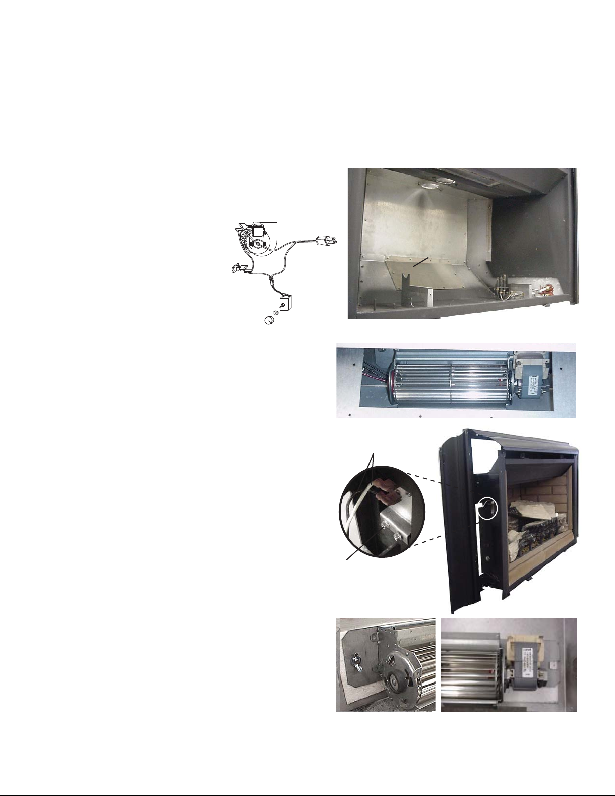
5.0 REPLACEMENT BLOWER INSTALLATION
The Napoleon® gas appliance comes standard with a blower, a heat sensor, variable on/off speed control
and a power cord. Because the blower is thermally activated, when turned on, it will automatically start
approximately 15 minutes after lighting the appliance and will run for approximately 30 minutes after the
appliance has been turned off. Use of the fan increases the output of heat. Air, drawn in through the lower slot,
is driven up the back of the fi rebox, and exhausted as hot air through the upper slot.
A. Turn off the electrical power and the gas supply to the appliance.
B. Remove the fi re viewing door. Remove the logs,
log support and back wall.
15
C. Remove the blower
access door held
black
BLOWER
red
on with 10 screws.
Replace the blower
access door gasket
when changing the
blower.
THERMAL
SWITCH
white
VARIABLE
SPEED
SWITCH
D. Disconnect the
two blower wires. Remove the blower bracket
secured with one wing nut and lock washer.
For thermodisc replacement: Remove the "Z"
shaped mounting bracket secured to the fi rebox
wall behind the left side control door. Remove
the thermodisc from the bracket and replace.
E. Replace the blower using the existing bracket.
Slide the vibration reducing pad (A) into the
clip (C) and up against the threaded stud (B) at
the other end. The blower must be able to be
positioned entirely onto the pad.
Slide the blower into the clip (C). Secure to the
threaded stud using the existing lock washer and
wing nut. Ensure that the blower does not touch
the fi replace base or the fi rebox.
BLOWER
ACCESS
DOOR
SHOWN WITH LOG SUPPORT AND BACK WALL REMOVED.
BLOWER THROUGH ACCESS DOOR
BLOWER WIRES
F. Reconnect the two wires. Holding the
replacement gasket in place, re-attach the blower
access door. Replace the backwall, logs and log
support. Reinstall the fi re viewing door.
G. Turn the gas supply and electricity back on.
Drywall dust will penetrate into the blower
bearings causing irreparable damage and must
be prevented from coming into contact with the
blower or its compartment. Any damage resulting
from this condition is not covered by the warranty
policy.
THERMODISC BRACKET
ASSEMBLY
B
b
a
A
C
W415-0734 / D / 02.03.12
16
6.0 OPERATION
WHEN LIGHTING AND RE-LIGHTING, THE GAS KNOB CANNOT BE TURNED FROM PILOT
UNLESS THE KNOB IS DEPRESSED.
1. STOP! READ THE SAFETY INFORMATION ON THE OPERATING LABEL.
2. TURN OFF ALL ELECTRIC POWER TO THE FIREPLACE.
3. TURN THE GAS KNOB CLOCKWISE TO OFF.
4. WAIT FIVE (5) MINUTES TO CLEAR OUT ANY GAS. IF YOU SMELL GAS, INCLUDING
NEAR THE FLOOR, STOP! FOLLOW “B” ON THE OPERATING LABEL. IF YOU DON’T
SMELL GAS GO TO THE NEXT STEP.
5. IF FIREPLACE IS EQUIPPED WITH FLAME ADJUSTMENT VALVE TURN CLOCKWISE TO
OFF.
6. FIND PILOT LOCATED IN FRONT OF BACK LOG.
7. TURN GAS KNOB COUNTER-CLOCKWISE TO PILOT.
8. DEPRESS AND HOLD GAS KNOB WHILE LIGHTING THE PILOT WITH THE PUSH
BUTTON IGNITOR. KEEP KNOB FULLY DEPRESSED FOR ONE MINUTE, THEN
RELEASE. IF PILOT DOES NOT CONTINUE TO BURN REPEAT STEPS 3 THROUGH 7.
9. WITH PILOT LIT, TURN GAS KNOB COUNTER-CLOCKWISE TO ON.
10. IF EQUIPPED WITH FLAME ADJUSTMENT VALVE, PUSH AND TURN KNOB TO HIGH.
11. IF EQUIPPED WITH REMOTE ON-OFF SWITCH, MAIN BURNER MAY NOT COME ON
WHEN YOU TURN THE VALVE TO ON OR HIGH. REMOTE SWITCH MUST BE IN THE ON
POSITION TO IGNITE BURNER.
12. TURN ON ALL ELECTRIC POWER TO THE FIREPLACE.
GAS KNOB TO OFF
BOUTON DU GAZ A
“OFF”
LIGHTING INSTRUCTIONS / INSTRUCTIONS D'ALLUMAGE
LORSQUE LE GAZ EST ALLUME OU RE-ALLUME LE BOUTON DE GAZ NE PEUT PAS
ETRE TOURNE DE PILOTE A FERME A MOINS QU'IL SOIT ENFONCE.
1. ARRETEZ! LISEZ LES INSTRUCTIONS DE SECURITE SUR L’ETIQUETTE DE
FONCTIONNEMENT.
2. COUPEZ L'ALIMENTATION ELECTRIQUE AU FOYER.
3. TOURNEZ LE BOUTON DE CONTROLE DU GAZ VERS LA DROITE A
"OFF".
4. ATTENDEZ CINQ (5) MINUTES AFIN D'EVACUER TOUT LES GAZ. SI VOUS
SENTEZ LE GAZ COMPRIS PRES DU REVETEMENT, ARRETEZ! OBSERVEZ
L'ITEM "B" SUR L’ETIQUETTE DE FONCTIONNEMENT. SI VOUS NE SENTEZ
PAS LE GAZ, CONTINUEZ A L'ETAPE SUIVANTE.
5. SI L'APPA REIL EST MUNI D' UNE SOUPAPE DE REGLAGE DE LA FLAMME.
TOURNEZ LE BOUTON VERS LA DROITE A "OFF".
6. LOCALISEZ LA VEILLEUSE DEVENT LA BUCHE ARRIERE.
7. TOURNE LE BOUTON DU GAZ VERS LA GAUCHE A PILOTE.
8. ENFONCEZ ET GARDEZ LE BOUTON DU GAZ ENFONCE PENDANT QUE
VOUS ALLUMEZ LA VEILLEUSE EN PRENFONCE PENDANT UNE MINUTE ET
RE-LA CHEZ-LE . SI LA VEI LLEUSE NE RE STE PAS A LLUMEE, REPETEZ LES
ETAPES DE 3 A 7.
9. LORSQUE LA VEILLEUSE EST ALLUMEE, TOURNEZ LE BOUTON DU GAZ
VERS LA GAUCHE A "ON".
10. SI L'APPAREIL EST MUNI D'UNE SOUPAPE DE REGLAGE DE LA FLAMME,
PRESSEZ ET TOURNEZ LE BOUTON A "HIGH".
11. SI L'APPAREIL EST MUNI D'UNE INTERRUPTEUR OUVERT/FERME A DISTANCE,
LE BRULEUR PRINCIPAL PEUT NE PAS S'ALLUMER QUAND VOUS TOURNEZ
LA SOUPAPE OUVERT OU "HIGH". L'INTERRUPTEUR A DISTANCE DOIT ETRE
EN POSITION OUVERT POUR QUE LE B RULEUR PRINCIPAL S'ALLUME.
12. RE-ALIMENTEZ L'APPAREIL EN ELECTRICIT E.
TO TURN OFF GAS / COUPER L’ALIMENTATION EN GAZ
1. TURN OFF ALL ELECTRIC POWER TO THE FIREPLACE IF SERVICE IS TO
BE PERFORMED.
2. PUSH IN GAS CONTROL KNOB SLIGHTLY AND TURN CLOCKWISE
TO OFF. DO NOT FORCE.
OPERATI NG IN STRU CTION S / IN STRU CTION S D'O PERATION
FOR YOUR SAFETY READ BEFORE OPERATING / POUR VOTRE SECURITE LIRE AVANT DE FAIRE FONCTIONNER
WARNING: DO NOT TURN ON IF CHILDREN OR OTHER AT RISK
INDIVIDUALS ARE NEAR THE FIREPLACE. IF YOU DO NOT FOLLOW
THESE INSTRUCTIONS EXACTLY, A FIRE OR EXPLOSION MAY RESULT
&$86,1*3523(57<'$0$*(3(5621$/,1-85<25/2662)/,)(
INITIAL LIGHTING OF THE PILOT AND MAIN BURNERS MUST BE DONE
WITH THE GLASS DOOR OFF.DO NOT CONNECT VALVE OR WALL
SWITCH TO ELECTRICITY. SEE INSTALLATION INSTRUCTIONS.
DO NOT CONNECT VALVE OR WALL SWITCH TO ELECTRICITY.
SEE INSTALLATION INSTRUCTIONS.
A. THIS FIREPLACE IS EQUIPPED WITH A PILOT WHICH MUST BE LIT BY
HAND WHILE FOLLOWING THESE INSTRUCTIONS EXACTLY.
B. BEFORE OPERATING SMELL ALL AROUND THE FIREPLACE AREA FOR GAS AND
NEXT TO THE FLOOR BECAUSE SOME GAS IS HEAVIER THAN AIR AND WILL
SETTLE ON THE FLOOR.
WHAT TO DO IF YOU SMELL GAS:
7URN OFF ALL GAS TO THE FIREPLACE.
OPEN WINDOWS.
DO NOT TRY TO LIGHT ANY APPLIANCE.
DO NOT TOUCH ANY ELECTRIC SWITCH; DO NOT USE ANY PHONE IN
YOUR BUILDING.
IMMEDIATELY CALL YOUR GAS SUPPLIER FROM A NEIGHBOUR’S PHONE.
FOLLOW THE GAS SUPPLIER’S INSTRUCTIONS.
IF YOU CANNOT REACH YOUR GAS SUPPLIER , CALL THE FIRE DEPARTMENT.
C. USE ONLY YOUR HAND TO TURN THE GAS CONTROL KNOB / MANUAL SHUT-OFF
KNOB. NEVER USE TOOLS. IF THE KNOB WILL NOT TURN BY HAND, DO NOT TRY
TO REPAIR IT. CALL A QUALIFIED SERVICE TECHNICIAN. FORCE OR ATTEMPTED
REPAIR MAY RESULT IN A FIRE OR EXPLOSION.
D. DO NOT USE THIS FIREPLACE IF ANY PART HAS BEEN UNDER WATER. IMMEDI-
ATELY CALL A QUALIFIED SERVICE TECHNICIAN TO INSPECT THE FIREPLACE AND
REPLACE ANY PART OF THE CONTROL SYSTEM AND ANY GAS CONTROL WHICH
HAS BEEN UNDER WATER.
1. COUPEZ L'ALIMENTATION ELECTRIQUE AU FOYER SI LE SERVICE EST
EFFECTUE.
2. ENFONCEZ LEGEREMENT LE BOUTON DE CONTROLE DU GAZ ET TOURNEZ
VERS LA DROITE A “OFF”. NE FORCEZ PAS.
ATTENTION:
INDIVIDUS À RISQUE SONT À PROXIMITÉ DU FOYER. QUICONQUE NE
RESPECTE PAS À LA LETTRE LES INSTRUCTIONS DANS LA PRÉSENTE
NOTICE RISQUE DE DÉCLENCHER UN INCENDIE OU UN EXPLOSION
ENTRAÎNANT DES DOMMAGES, DES BLESSURES OU LA MORT.
L’ALLUMAGE INITIAL DE LA VEILLEUSE ET DU BRÛLEUR PRINCIPAL
DOIT SE FAIRE AVEC LA PORTE VITRÉE ENLEVÉE.
NE RACCORDEZ PAS LA SOUPAPE OU L’INTERRUPTEUR MURAL A
L’ÉLECTRICITÉ. CONSULTEZ LES INSTRUCTIONS D’INSTALLATION.
A. CET APPAREIL EST MUNI D’UNE VEILLEUSE QUI DOIT ÊTRE ALLUMEÉ MANUELLEMENT.
RESPECTEZ LES INSTRUCTIONS CI-DESSOUS À LA LETTRE.
B. AVANT D’ALLUMER LA VEILLEUSE, RENIFLEZ TOUT AUTOUR DE L’APPAREIL POUR DÉCELER
UNE ODOUR DE GAZ. RENIFLEZ PRÈS DU PLANCHER, CAR CERTAINS GAZ SONT PLUS
LOURDS QUE L’AIR ET PEUVENT S’ACCUMULER AU NIVEAU DU SOL.
QUE FAIRE SI VOUS SENTEZ UN ODEUR DE GAZ :
&283(=(17,(5(0(17/$/,0(177,21'(*$=35,1&,3$/(
2895(=/(6)(1(75(6
1(3$67(17(5'¶$//80(5'¶$33$5(,/
1(728&+(=¬$8&81,17(55837(851(3$692866(59,5'(67e/e3+21(66(
TROUVANT DANS LE BÂTIMENT.
$33(/(=,00e',$7(0(179275()2851,66(85'(*$='(38,68192,6,168,9(=/(6
INSTRUCTIONS DU FOURNISSEUR.
6,92861(3289(=5(-2,1'5(/()2851,66(85$33(/(=/(6(59,&('(6,1&(1'-
IES.
& 1(32866(52872851(5/$0$1(77('¶$'0,66,21'8*$=48¶¬/$0$,11(-$0$,6
EMPLOYER D’OUTIL À CETTE FIN. SI LA MANETTE RESTE COINCÉE, NE TENTEZ PAS DE LA
RÉPARER; APPELEZ UN TECHNICIEN QUALIFIÉ. QUICONQUE TENTE DE FORCER LA
MANETTE OU DE LA RÉPARER PEUT PROVOQUER UNE EXPLOSION OU UN INCENDIE.
D. N’UTILISEZ PAS CET APPAREIL S’IL A ÉTÉ PLONGÉ DANS L’EAU, MÊME PARTIELLEMENT.
FAITES INSPECTER L’APPAREIL PAR UN TECHNICIEN QUALIFIÉ ET REMPLACEZ TOUTE
PARTIE DU SYSTÈME DE CONTRÔLE ET TOUTE COMMANDE QUI ONT ÉTÉ PLONGÉS DANS
L’EAU.
NE PAS ALLUMER SI DES ENFANTS OU D’AUTRES
W385-0201 / C
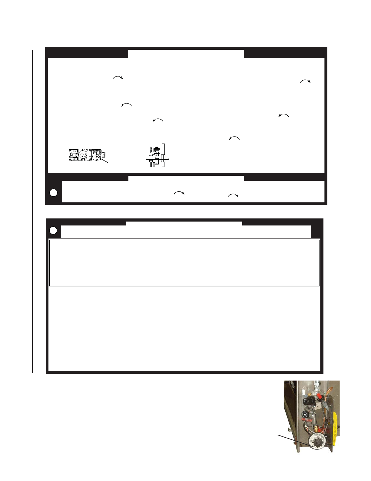
6.1 REAR BURNER CONTROL
The purpose of the rear burner is to increase heat output or BTUs of the appliance
and will only operate when the main burner is functioning. To turn the rear burner on,
simply depress the burner control knob (located in the valve compartment at the left
hand side below the piezo ignitor) and rotate the knob counter-clockwise to 'high'.
In order to achieve maximum turn down rate, the rear burner must be turned off.
W415-0734 / D / 02.03.12
Rear burner
control knob
7.0 ADJUSTMENTS
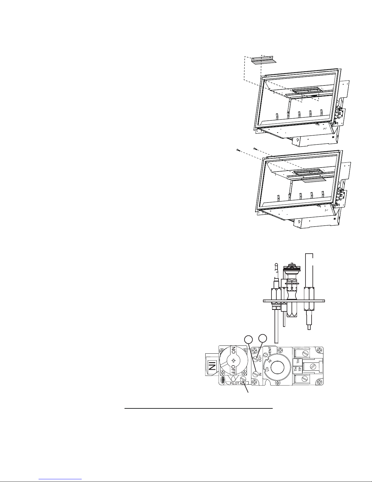
7.1 VENT RESTRICTION
Vertical terminations running longer than fi fteen feet may display a
very active fl ame. When this is not desirable, a vent restrictor could
be installed. This restrictor plate will reduce the velocity of the exhaust
gases, slowing down the fl ame pattern and creating a more traditional
appearance.
A. Remove the glass viewing door and logs.
B. Secure the restrictor plate as described.
C. Replace logs and viewing door.
Line up the holes on the vent restrictor with the holes on the bracket
attached to the roof of the fi rebox.
Secure the vent restrictor into position using the two screws supplied.
17
7.2 PILOT BURNER ADJUSTMENT
Remove the pilot screw cap. Adjust the pilot screw to provide properly
sized fl ame. Turn in a clockwise direction to reduce the gas fl ow.
Re-install the pilot screw cap.
Inlet pressure can be checked by turning screw (A)
counter-clockwise until loosened and then placing pressure
gauge tubing over the test point. Gauge should read 7”
(minimum 4.5”) water column for natural gas or 13” (11” minimum)
water column for propane. Check that main burner is operating on “HI”.
Outlet pressure can be checked the same as above using screw (B).
Gauge should read 3.5” water column for natural gas or 10” water
column for propane. Check that main burner is operating on “HI”.
AFTER TAKING PRESSURE READINGS, TIGHTEN
SCREWS FIRMLY TO SEAL. DO NOT OVER
TORQUE. LEAK TEST.
PILOT
BURNER
THERMOCOUPLE
B
A
T
O
L
I
P
PILOT SCREW
39.6
THERMOPILE
W415-0734 / D / 02.03.12
 Loading...