

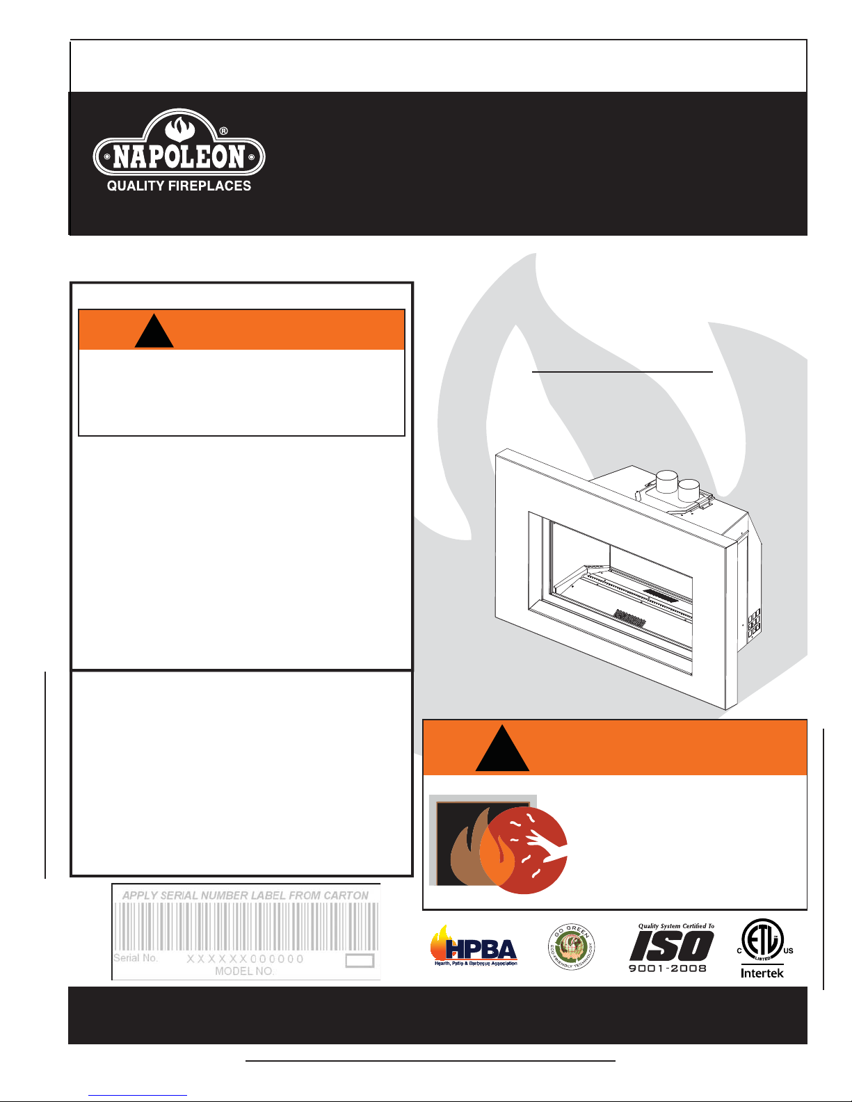
Napoleon GDI-30GN, GDI-30GP Installation And Operating Instructions Manual
INSTALLER: LEAVE THIS MANUAL WITH THE APPLIANCE.
CONSUMER: RETAIN THIS MANUAL FOR FUTURE REFERENCE.
INSTALLATION AND
OPERATING INSTRUCTIONS
CERTIFIED UNDER CANADIAN AND AMERICAN NATIONAL STANDARDS: CSA 2.33, ANSI Z21.88 FOR VENTED GAS FIREPLACE HEATERS.
CERTIFIED FOR CANADA AND UNITED STATES USING ANSI/CSA METHODS.
SAFETY INFORMATION
1
!
WARNING
If the information in these instructions
are not followed exactly, a fi re or
explosion may result causing property
damage, personal injury or loss of life.
- Do not store or use gasoline or other fl ammable
vapors and liquids in the vicinity of this or any
other appliance.
- WHAT TO DO IF YOU SMELL GAS:
• Do not try to light any appliance.
• Do not touch any electrical switch; do not use
any phone in your building.
• Immediately call your gas supplier from a
neighbour’s phone. Follow the gas supplier’s
instructions.
• If you cannot reach your gas supplier, call the
fi re department.
- Installation and service must be performed by a
qualifi ed installer, service agency or the supplier.
This appliance may be installed as an OEM
installation in manufactured home (USA only) or
mobile home and must be installed in accordance
with the manufacturer’s instructions and the
Manufactured Home Construction and Safety
Standard, Title 24 CFR, Part 3280, in the United
States or the Standard for Installation in Mobile
Homes, CAN/CSA Z240 MH, in Canada.
This appliance is only for use with the type(s) of
gas indicated on the rating plate. A conversion kit
is supplied with the appliance.
GDI-30GN
NATURAL GAS
GDI-30GP
PROPANE
!
WARNING
HOT GLASS WILL CAUSE
BURNS.
DO NOT TOUCH GLASS UNTIL
COOLED.
NEVER ALLOW CHILDREN TO
TOUCH GLASS.
Wolf Steel Ltd., 24 Napoleon Rd., Barrie, ON, L4M 0G8 Canada /
103 Miller Drive, Crittenden, Kentucky, USA, 41030
Phone (705)721-1212 • Fax (705)722-6031 • www.napoleonfi replaces.com • ask@napoleonproducts.com
$10.00
1.28A
W415-0832 / A / 02.14.11

2
TABLE OF CONTENTS
1.0 INSTALLATION OVERVIEW 3
2.0 INTRODUCTION 4
2.1 DIMENSIONS 5
2.2 GENERAL INSTRUCTIONS 5
2.3 GENERAL INFORMATION 6
2.4 RATING PLATE INFORMATION 7
3.0 INSTALLATION 8
3.1 INSERT LEVELLING 8
3.2 CHIMNEY CONNECTION 9
3.3 GAS INSTALLATION 10
3.4 OPTIONAL WALL SWITCH / THERMOSTAT 10
4.0 FRAMING 11
4.1 MINIMUM MANTEL CLEARANCES 11
5.0 FINISHING 12
5.1 4 SIDED SURROUND 12
5.2 DOOR REMOVAL AND INSTALLATION 12
5.3 MEDIA TRAY INSTALLATION 13
5.4 MEDIA INSTALLATION 13
5.5 LOGO PLACEMENT 13
6.0 REPLACEMENT BLOWER INSTALLATION 14
7.0 OPERATION 15
7.1 OPERATING AND LIGHTING INSTRUCTIONS 15
7.2 ANTI CONDENSATION SWITCH 16
8.0 WIRING DIAGRAM 16
8.1 NIGHT LIGHTTM WIRING DIAGRAM 17
9.0 ADJUSTMENTS 18
9.1 PILOT BURNER ADJUSTMENT 18
9.2 VENTURI ADJUSTMENT 18
9.3 FLAME CHARACTERISTICS 19
10.0 MAINTENANCE 19
10.1 LAMP REPLACEMENT 20
10.2 LAMP ASSEMBLY REPLACEMENT 20
10.3 DOOR GLASS REPLACEMENT 21
10.4 CARE OF GLASS 21
11.0 REPLACEMENTS 22
12.0 TROUBLE SHOOTING 24
13.0 WARRANTY 27
14.0 SERVICE HISTORY 28
NOTE: Changes, other than editorial, are denoted by a vertical line in the margin.
W415-0832 / A / 02.14.11
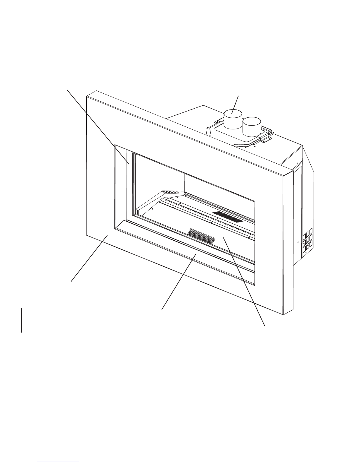
1.0 INSTALLATION OVERVIEW
Door, see “FINISHING - DOOR
REMOV AL AND INST ALLA TION”
section.
3
Venting, see “INSTALLATION - CHIMNEY
CONNECTION” section.
Surround, see “FINISHING - 4 SIDED
SURROUND INSTALLATION” section.
Rating Plate, see “RATING PLATE
INFORMATION” section.
Glass, see “FINISHING - GLASS
BURNER INSTALLATION” section.
W415-0832 / A / 02.14.11

4
2.0 INTRODUCTION
• THIS APPLIANCE IS HOT WHEN OPERATED AND CAN CAUSE SEVERE BURNS IF CONTACTED.
• ANY CHANGES OR ALTERATIONS TO THIS APPLIANCE OR ITS CONTROLS CAN BE DANGEROUS
AND IS PROHIBITED.
• Do not operate appliance before reading and understanding operating instructions. Failure to operate
appliance according to operating instructions could cause fi re or injury.
• Risk of fi re or asphyxiation do not operate appliance with fi xed glass removed.
• Do not connect 110 volts to the control valve.
• Risk of burns. The appliance should be turned off and cooled before servicing.
• Do not install damaged, incomplete or substitute components.
• Risk of cuts and abrasions. Wear protective gloves and safety glasses during installation. Sheet metal edges
may be sharp.
• Do not burn wood or other materials in this appliance.
• Children and adults should be alerted to the hazards of high surface temperature and should stay away to
avoid burns or clothing ignition.
• Young children should be carefully supervised when they are in the same room as the appliance. Toddlers,
young children and others may be susceptible to accidental contact burns. A physical barrier is recommended
if there are at risk individuals in the house. To restrict access to an appliance or stove, install an adjustable
safety gate to keep toddlers, young children and other at risk individuals out of the room and away from hot
surfaces.
• Clothing or other fl ammable material should not be placed on or near the appliance.
• Due to high temperatures, the appliance should be located out of traffi c and away from furniture and draperies.
• Ensure you have incorporated adequate safety measure to protect infants/toddlers from touching hot surfaces.
• Even after the appliance is out, the glass and/or screen will remain hot for an extended period of time.
• Check with your local hearth specialty dealer for safety screens and hearth guards to protect children from hot
surfaces. These screens and guards must be fastened to the fl oor.
• Any safety screen or guard removed for servicing must be replaced prior to operating the appliance.
• The appliance is a vented gas-fi red appliance. Do not burn wood or other materials in the appliance
• It is imperative that the control compartments, burners and circulating blower and its passageway in the
appliance and venting system are kept clean. The appliance and its venting system should be inspected
before use and at least annually by a qualifi ed service person. More frequent cleaning may be required due
to excessive lint from carpeting, bedding material, etc. The appliance area must be kept clear and free from
combustible materials, gasoline and other fl ammable vapors and liquids.
• Under no circumstances should this appliance be modifi ed.
• This appliance must not be connected to a chimney fl ue pipe serving a separate solid fuel burning appliance.
• Do not use this appliance if any part has been under water. Immediately call a qualifi ed service technician to
inspect the appliance and to replace any part of the control system and any gas control which has been under
water.
• Do not operate the appliance with the glass door removed, cracked or broken. Replacement of the glass
should be done by a licensed or qualifi ed service person.
• Do not strike or slam shut the appliance glass door.
• When equipped with pressure relief doors, they must be kept closed while the appliance is operating to
prevent exhaust fumes containing carbon monoxide, from entering into the home. Temperatures of the exhaust
escaping through these openings can also cause the surrounding combustible materials to overheat and catch
fi re.
• Only doors / optional fronts certifi ed with the unit are to be installed on the appliance.
• Keep the packaging material out of reach of children and dispose of the material in a safe manner. As with all
plastic bags, these are not toys and should be kept away from children and infants.
• As with any combustion appliance, we recommend having your appliance regularly inspected and serviced as
well as having a Carbon Monoxide Detector installed in the same area to defend you and your family against
Carbon Monoxide.
• Ensure clearances to combustibles are maintained when building a mantel or shelves above the appliance.
Elevated temperatures on the wall or in the air above the appliance can cause melting, discolouration or
damage of decorations, a T.V. or other electronic components.
!
WARNING
3.2B
W415-0832 / A / 02.14.11
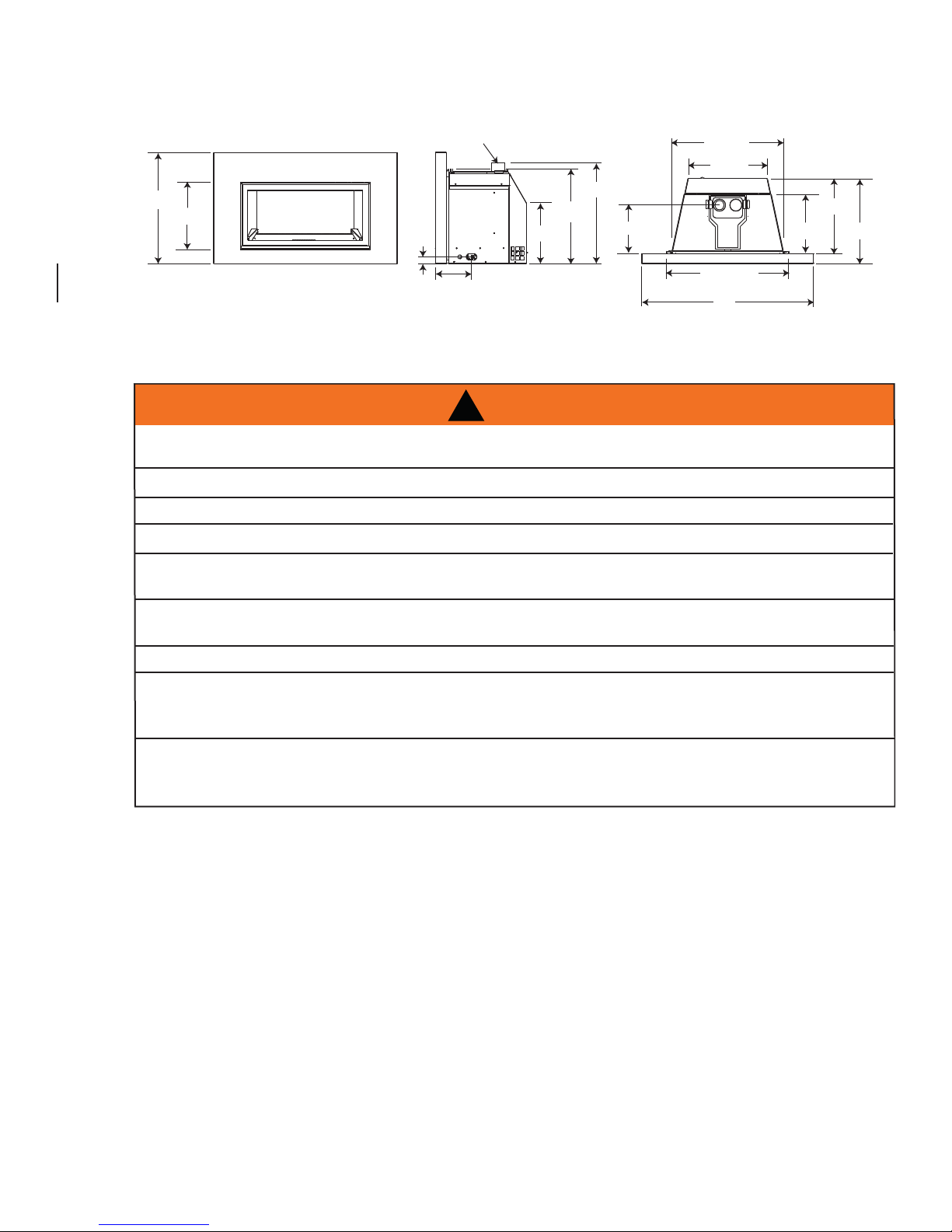
2.1 DIMENSIONS
5
25 ½”
15
1
/8”
2.2 GENERAL INSTRUCTIONS
ALWAYS LIGHT THE PILOT WHETHER FOR THE FIRST TIME OR IF THE GAS SUPPLY HAS RUN OUT,
WITH THE GLASS DOOR OPENED OR REMOVED.
PROVIDE ADEQUATE CLEARANCE FOR SERVICING AND OPERATING THE APPLIANCE.
NEVER OBSTRUCT THE FRONT OPENING OF THE APPLIANCE.
OBJECTS PLACED IN FRONT OF THE APPLIANCE MUST BE KEPT A MINIMUM OF 48” FROM THE
3” Ø COLLARS
23 1/8”
21 3/4”
3
/8”
1
7 ¼”
!
13 ¾”
WARNING
11
1
PROVIDE ADEQUA TE VENTILA TION.
FRONT FACE OF THE UNIT.
/8”
27 ½”
5
19
1
30
42”
/8”
/16”
13 ¾”
17
7
/8”
20
3
/8”
SURFACES AROUND AND ESPECIALLY ABOVE THE APPLIANCE CAN BECOME HOT. AVOID CONTACT
WHEN THE APPLIANCE IS OPERATING.
FIRE RISK. EXPLOSION HAZARD.
HIGH PRESSURE WILL DAMAGE VALVE. DISCONNECT GAS SUPPLY PIPING BEFORE PRESSURE TESTING GAS
LINE AT TEST PRESSURES ABOVE 1/2 PSIG. CLOSE THE MANUAL SHUT-OFF VALVE BEFORE PRESSURE
TESTING GAS LINE AT TEST PRESSURES EQUAL TO OR LESS THAN 1/2 PSIG.
USE ONLY WOLF STEEL APPROVED OPTIONAL ACCESSORIES AND REPLACEMENT PARTS WITH THIS APPLIANCE.
USING NON-LISTED ACCESSORIES (BLOWERS, DOORS, LOUVRES, TRIMS, GAS COMPONENTS, VENTING
COMPONENTS, ETC.) COULD RESULT IN A SAFETY HAZARD AND WILL VOID THE WARRANTY AND CERTIFICATION.
THIS GAS APPLIANCE SHOULD BE INSTALLED AND SERVICED BY A QUALIFIED INSTALLER to
conform with local codes. Installation practices vary from region to region and it is important to know the
specifi cs that apply to your area, for example in Massachusetts State:
• This product must be installed by a licensed plumber or gas fi tter when installed within the commonwealth
of Massachusetts.
• The appliance damper must be removed or welded in the open position prior to installation of a appliance
insert or gas log.
• The appliance off valve must be a “T” handle gas cock.
• The fl exible connector must not be longer than 36 inches.
• A Carbon Monoxide detector is required in all rooms containing gas fi red appliances.
• The appliance is not approved for installation in a bedroom or bathroom unless the unit is a direct vent
sealed combustion product.
W415-0832 / A / 02.14.11
6
A
A
The installation must conform with local codes or, in
absence of local codes, the National Gas and Propane
Installation Code CSA B149.1 in Canada, or the National
Fuel Gas Code, ANSI Z223.1 / NFPA 54 in the United
States. Suitable for mobile home installation if installed in
accordance with the current standard CAN/CSA Z240MH
Series, for gas equipped mobile homes, in Canada or
NSI Z223.1 and NFPA 54 in the United States.
s long as the required clearance to combustibles is
maintained, the most desirable and benefi cial location for an appliance is in the center of a building, thereby
allowing the most effi cient use of the heat created. The location of windows, doors and the traffi c fl ow in the
room where the appliance is to be located should be considered. If possible, you should choose a location
where the vent will pass through the house without cutting a fl oor or roof joist.
If the appliance is installed directly on carpeting, vinyl tile or other combustible material other than wood
fl ooring, the appliance shall be installed on a metal or wood panel extending the full width and depth.
Some appliances have optional fans or blowers. If an optional fan or blower is installed, the junction box must
be electrically connected and grounded in accordance with local codes, use the current CSA C22.1 Canadian
Electrical Code in Canada or the ANSI/NFPA 70 National Electrical code in the United States.
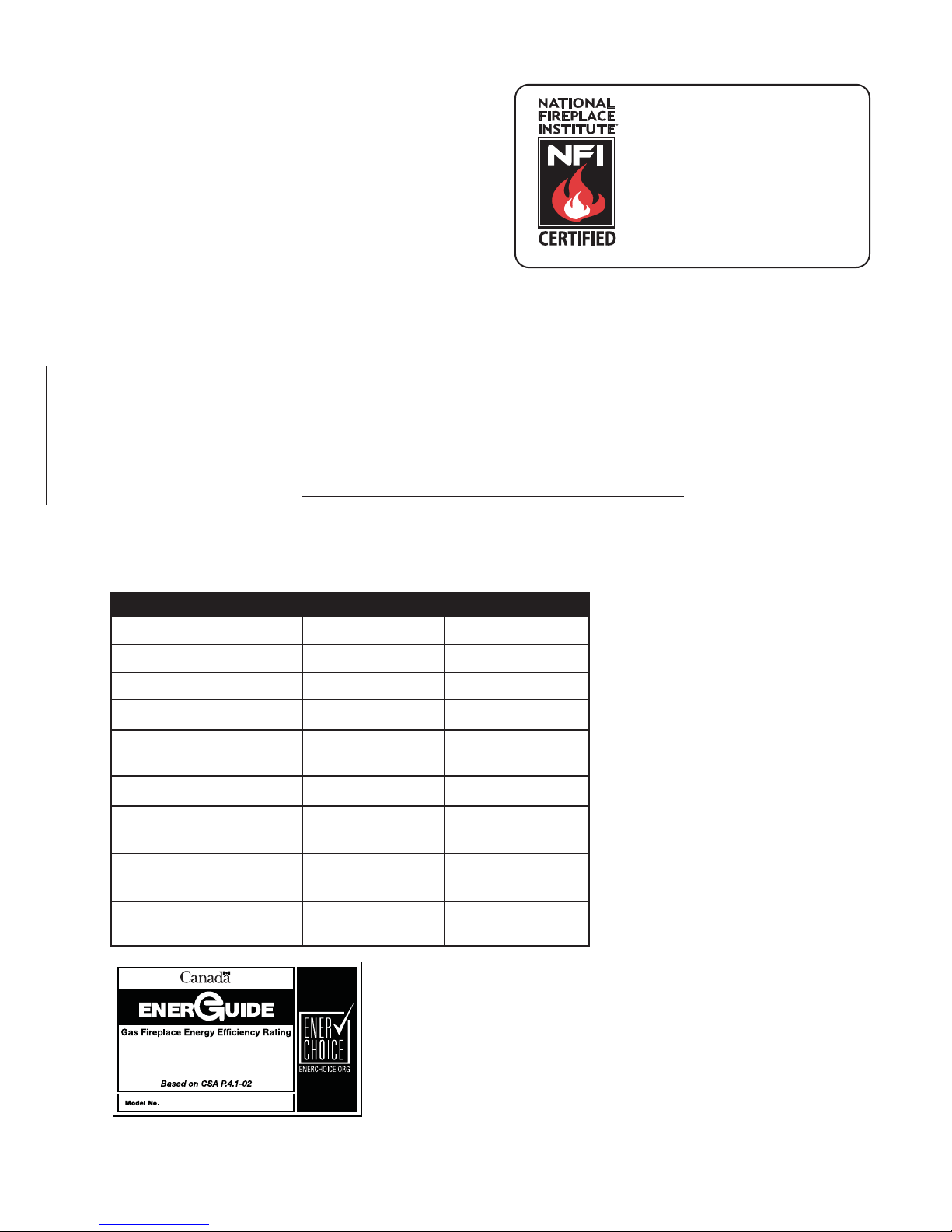
2.3 GENERAL INFORMATION
www.ncertied.org
We suggest that our gas
hearth products be installed
and serviced by professionals
who are certied in the U.S.
by the National Fireplace
®
Institute
(NFI) as NFI Gas
Specialists
4.1A
FOR YOUR SA TISFACTION, THIS APPLIANCE HAS BEEN TEST-FIRED TO ASSURE ITS OPERATION AND
QUALITY!
GDI-30G
NG LP
Altitude (FT) 0-4,500 0-4,500
Max. Input (BTU/HR) 24,500 24,500
Max. Output (BTU/HR) 20,825 20,825
Effi ciency
(w/the fan on)
A.F.U.E. 82% 82%
Min. Inlet Gas Supply
Pressure
Max. Inlet Gas Supply
Pressure
Manifold Pressure (Under
Flow Conditions)
4.5" Water Column 1 1" Water Column
3.5" Water Column 10" Water Column
85% 85%
7" Water Column 13" Water Column
When the appliance is installed at elevations above 4,500ft, and in the absence of
specifi c recommendations from the local
authority having jurisdiction, the certifi ed
high altitude input rating shall be reduced
at the rate of 4% for each additional
1,000ft. Expansion / contraction noises
during heating up and cooling down
cycles are normal and to be expected.
This appliance is not approved for closet
or recessed installations. It is approved for
bathroom, bedroom and bed-sitting room
installations and is suitable for mobile
homes. The natural gas model is suitable
for installation in a mobile home that is
permanently positioned on its site and
fuelled with natural gas.
64.5%
GDI-30G
W415-0832 / A / 02.14.11
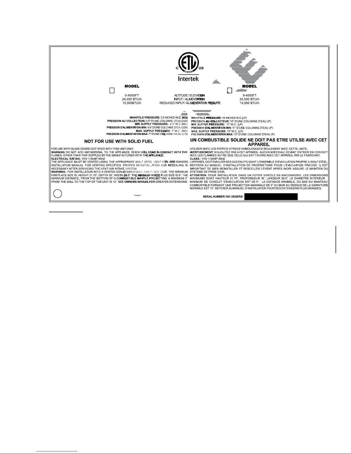
2.4 RATING PLATE INFORMATION
FO
FO
VIGUEUR AU CANADA OU AUVIGUEUR AU CANADA OU AU
RUCTION DE MAISONS MAN
MENT.MENT.
7
DIRECT VENT GAS FIREPLACE. APPROVED FOR BEDROOM, BATHROOM AND
BED-SITTING ROOM INSTALLATION. SUITABLE FOR MOBILE HOME INSTALLATION IF
INSTALLED IN ACCORDANCE WITH THE CURRENT STANDARD CAN/CSA Z240MH
SERIES GAS EQUIPPED MOBILE HOMES, IN CANADA OR IN THE UNITED STATES THE
MANUFACTURED HOME CONSTRUCTION AND SAFETY STANDARD, TITLE 24 CFR,
PART 3280. WHEN THIS US STANDARD IS NOT APPLIACABLE USE THE STANDARD FOR
FIRE SAFETY CRITERIA FOR MANUFACTURED HOME INSTALLATIONS, SITES AND
COMMUNITIES, ANSI / NFPA 501A.
MINIMUM AND MAXIMUM VERTICAL VENT LENGTHS ARE 10 FEET AND 35 FEET RESPECTIVELY. LES
LONGUEURS VERTICALES MINIMALES ET MAXIMALES SONT 10 PIEDS ET 35 PIEDS RESPECTIVEMENT.
CERTIFIED UNDER / HOMOLOGUE SELON LES NORMES: CSA 2.22b-2009, ANSI Z21.50b-2009 VENTED GAS FIREPLACE / FOYER AU GAZ AVEC EVACUATION.
GDI-30GN / CDI-30GN GDI-30GP / CDI-30GP
WOLF STEEL LTD.
24 NAPOLEON ROAD, BARRIE. ONTARIO L4M 4Y8 CANADA
MINIMUM AND MAXIMUM VERTICAL VENT LENGTHS ARE 10 FEET AND 35 FEET RESPECTIVELY. LES
LONGUEURS VERTICALES MINIMALES ET MAXIMALES SONT 10 PIEDS ET 35 PIEDS RESPECTIVEMENT.
FOYER A GAZ VENTILE DIRECT. HOMOLOGUE POUR INSTALLATION DANS UNE
CHAMBRE A COUCHER, UNE SALLE DE BAIN ET UN STUDIO. APPROPRIE POUR
INSTALLATION DANS UNE MAISON MOBILE SI SON INSTALLATION CONFORME AUX
EXIGENCES DE LA NORME CAN/CSA Z240MH SERIE DE MAISONS MOBILES EQUIPEES
AU GAZ, EN VIGUEUR AU CANADA OU AUX ETATS-UNE DE LA NORME DE SECURITE
ET DE CONSTRUCTION DE MAISONS MANUFACTUREES, TITRE 24 CFR, SECTION
3280. DANS LE CAS OU CETTE NORME D’ETATS-UNIS NE PEUT ETRE APPLIQUEE, SE
REFERER A LA NORME RELATIVE AU CRITERE DE MESURES DE SECURITE CONTRE
L’INCENDIE POUR LES INSTALLATIONS DANS LES MAISONS MANUFACTURES, LES
SITES ET LES COMMUNAUTES, ANSI/NFPA 501A.
GDI/CDI-30G
W385-0492 / C
INSTALLER: It is your responsibility to check off the appropriate box on the rating plate according to
the model, venting and gas type of the appliance.
For rating plate location, see “INSTALLATION OVERVIEW” section.
This illustration is for reference only. Refer to the rating plate on the appliance for accurate information.
W415-0832 / A / 02.14.11
8
-
3.0 INSTALLATION
RISK OF FIRE, MAINTAIN SPECIFIED AIR SPACE CLEARANCES TO VENT PIPE AND APPLIANCE.
IF USING CO-AXIAL VENTING WITH SPACERS, THE VENT SYSTEM MUST BE SUPPORTED EVERY 3
FEET FOR BOTH VERTICAL AND HORIZONTAL RUNS. USE SUPPORTS OR EQUIVALENT
NON-COMBUSTIBLE STRAPPING TO MAINTAIN THE REQUIRED CLEARANCE FROM
COMBUSTIBLES. USE WOLF STEEL LTD. SUPPORT RING ASSEMBLY W010-0370 OR EQUIVALENT
NON-COMBUSTIBLE STRAPPING TO MAINTAIN THE MINIMUM CLEARANCE TO COMBUSTIBLES
FOR BOTH VERTICAL AND HORIZONTAL RUNS. SPACERS ARE ATTACHED TO THE INNER PIPE AT
PREDETERMINED INTERVALS TO MAINTAIN AN EVEN AIR GAP TO THE OUTER PIPE. THIS GAP IS
REQUIRED FOR SAFE OPERATION. A SPACER IS REQUIRED AT THE START, MIDDLE AND END OF
EACH ELBOW TO ENSURE THIS GAP IS MAINTAINED. THESE SPACERS MUST NOT BE REMOVED.
Clean out ashes from the inside of the wood-burning appliance. Make sure that the chimney and wood-burning
appliance are in a clean and sound condition and constructed of non-combustible materials. If necessary have
any repair work done by a qualifi ed person before installing the insert. Remove the existing appliance damper
or lock into an open position.
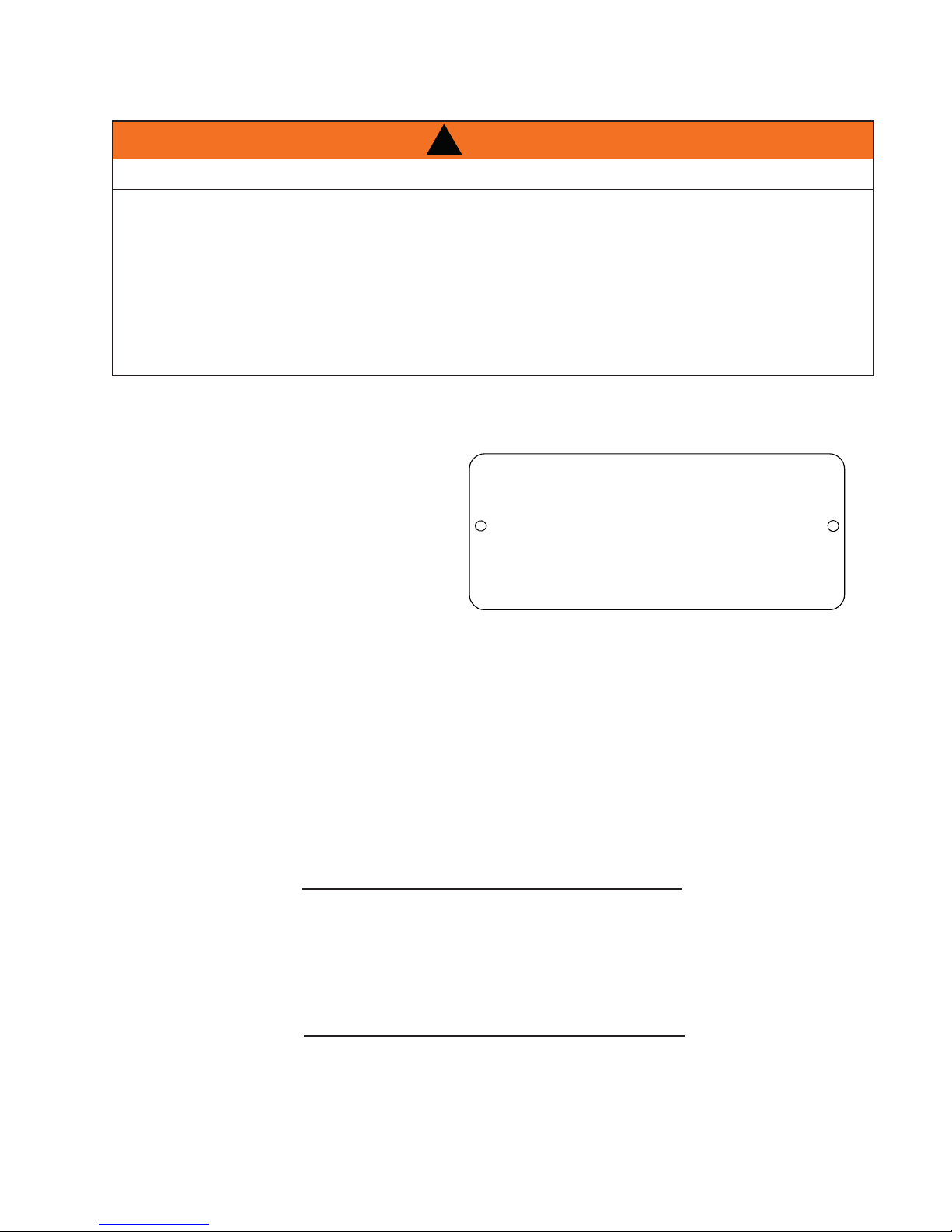
Using screws, attach the appliance warning tag
to the inside of the fi rebox of the appliance into
which the insert is being installed.
The sheet-metal parts of the appliance, in which
the gas appliance insert is to be installed, must
not be cut.
!
WARNING
WARNING: THIS FIREPLACE HAS BEEN CONVERTED FOR USE WITH A GAS FIREPLACE
INSERT ONLY AND CANNOT BE USED FOR BURNING WOOD OR SOLID FUELS UNLESS ALL ORIGINAL
PARTS HAVE BEEN REPLACED AND THE FIREPLACE IS RE-APPROVED BY THE AUTHORITY HAVING
JURISDICTION.
ATTENTION: CE FOYER A ETE CONVERTI AFIN D’ETRE UTILISE SEULEMENT
COMME FOYER ENCASTRE AU GAZ ET NE PEUT ETRE UTILSE POUR BRULER DU BOIS OU
TOUT AUTRE COMBUSTIBLE SOLIDE, SANS QUE TOUTES LES PIECES ORIGINALES AIENT
ETE REMPLACEES ET QUE LE FOYER SOIT APPROUVE DE NOUVEAU PAR LES AUTORITES
AYANT JURIDICTION.
ADVERTENCIA: ESTA CHIMENEA SE REMODELÓ PARA USARSE SOLO CON UNA
INSERCIÓN DE CHIMENEA A GAS Y NO PUEDE USARSE PARA QUEMAR MADERA NI COMBUSTIBLES
SÓLIDOS, A MENOS QUE SE HAYAN REEMPLAZADO TODAS LAS PIEZAS ORIGINALES, Y LA AUTORIDAD JURISDICCIONAL LA HAYA VUELTO A APROBAR.
W385-0199_B
If the wood-burning factory-built appliance has
no gas access hole(s) provided, an access hole of 1½ inch or less may be drilled through the lower sides or
bottom of the appliance in a proper workman like manner. This access hole must be plugged with non-combus
tible insulation after the gas supply line has been installed.
Ensure that existing chimney cleanouts fi t properly.
The refractory, glass doors, screen rails, screen mesh and log grates may be removed from the existing appli-
ance before installing the gas appliance insert.
Smoke shelves, shields and baffl es may be removed if attached by mechanical fasteners.
The ventilation openings in the existing appliance may be obstructed by the backer plates, aluminium trim etc.
but these parts are not to be applied so as to have an airtight seal.
3.1 INSERT LEVELLING
Move the appliance close to its fi nal position. This appliance is equipped with levelling screws located on the
base. Level using the levelling screws. Levelling the appliance will eliminate rocking or excessive noise when
the fan is in operation. Once the appliance is level, move it partially into place to allow for all connections to be
made. It is not practical to level the appliance once it has been installed. Determine the required depth prior to
installing the appliance and adjust the levelling screws accordingly.
68.4
67.2
W415-0832 / A / 02.14.11
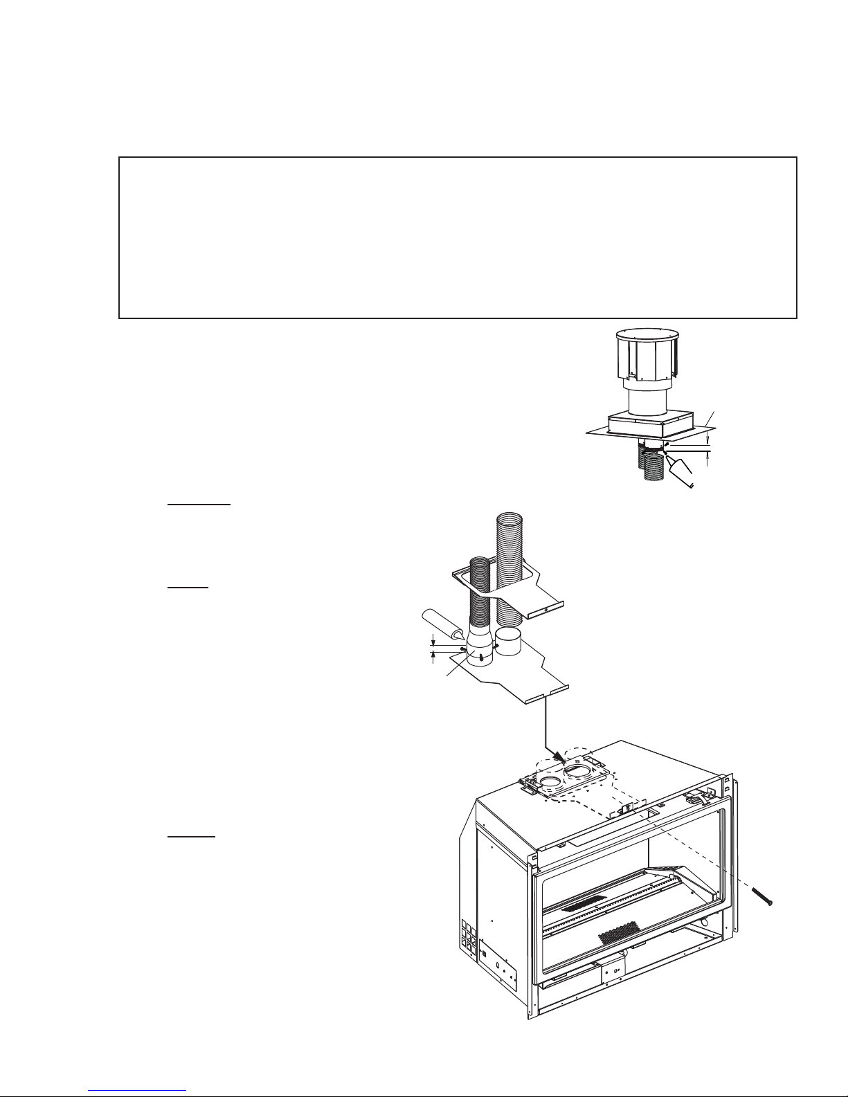
3.2 CHIMNEY CONNECTION
Chimney installation must conform to both national and local code requirements. The chimney must be lined
with one 2" or 3" diameter liner for intake and one 3" diameter liner for exhaust. The minimum and maximum
vent lengths are 10 and 35 feet respectively. Recommended Napoleon kits come in 3 lengths:
1-2" & 1-3" DOUBLE PLY ALUMINUM LINER-INLET AND EXHAUST & 2-3" TO 2" REDUCER:
2-3" DOUBLE PLY ALUMINUM LINER-INLET AND EXHAUST:
While the liners must be continuous from the appliance to the chimney cap, to
achieve the needed length, they may be coupled, using an approved coupler.
We recommend that exhaust vents that pass through unheated spaces, such as
tall exterior chimneys, be wrapped in a protective sleeve to minimize condensation and reverse fl ow symptoms. See Trouble Shooting for details.
This appliance is approved for use with a 2" liner for air intake and a 3" liner for
exhaust. For best performance, however, it is recommended to use two 3" liners.
If a 2" liner is used for the intake, it may be necessary to adjust the primary air
shutter.
A. OUTSIDE: Slip the one end of a liner a minimum of 2" over the sleeve
of the air terminal. Secure using
3 screws. Then seal the joint and
screw heads with high temperature
sealant. Repeat with the other liner.
NOTE: We recommend that the
other end of the exhaust liner be
marked to eliminate the exhaust
liner being connected to the
intake collar at the appliance.
B. Gently stretch the liners to the
required lengths and insert into the
chimney . Trim and fi t the fl ashing
plate to suit the chimney termination. Place the
air terminal onto the top of the chimney . Make
weather tight by sealing with caulking (not supplied). Fasten to the chimney with screws and
plugs (not supplied).
GDI-2320KT VENT KIT 20FT
GDI-2325KT VENT KIT 25FT
GDI-2335KT VENT KIT 35FT
GDI-320KT VENT KIT 20FT
GDI-325KT VENT KIT 25 FT
GDI-335KT VENT KIT 35 FT
3"
2"
LINER
LINER
HI-TEMP
SEALANT
SLIDER
2"
OVERLAP
MOUNTING
REDUCER
PLATE
INTAKE
INTAKE
EXHAUST
CONNECTION
ILLUSTRATED WITH A 2"
INTAKE LINER.
EXHAUST
9
FLASHING
PLATE
2” OVERLAP
SEALANT
HI-TEMP
C. INSIDE: Remove the securing screw from the
front of the vent mounting plate. Pull the vent
mounting plate only , back into the track, to the
front stop. Start the slider back into position.
Re-secure the screw. The insert may now be
pushed into its fi nal position inside the wood
burning appliance, and the screw tightened until
the slider has been pulled tight to the front stop.
D. Route the fl ex liners through the slider. Attach
and secure the liners to the vent mounting plate
using the same procedure as before, ensuring
that the marked exhaust liner is attached to the exhaust collar.
SECURING
SCREW
W415-0832 / A / 02.14.11
 Loading...