

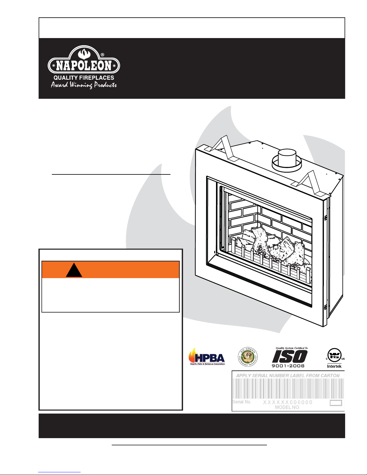
Napoleon BGD36CFPTR, GD36MN, GD36MP, BGD36CFGP, BGD36CFGN Installation And Operating Instructions Manual
INSTALLER: LEAVE THIS MANUAL WITH THE APPLIANCE.
CONSUMER: RETAIN THIS MANUAL FOR FUTURE REFERENCE.
INSTALLATION AND
OPERATING INSTRUCTIONS
CERTIFIED UNDER CANADIAN AND AMERICAN NATIONAL STANDARDS: CSA 2.33, ANSI Z21.88 FOR VENTED GAS FIREPLACE HEATERS.
BGD36CFNTR,
BGD36CFGN &
GD36MN
NATURAL GAS MODEL
BGD36CFPTR,
1
BGD36CFGP &
GD36MP
PROPANE GAS MODEL
CERTIFIED FOR CANADA AND UNITED STATES USING ANSI/CSA METHODS.
SAFETY INFORMATION
!
WARNING
If the information in these instructions are
not followed exactly, a fi re or explosion
may result causing property damage,
personal injury or loss of life.
- Do not store or use gasoline or other fl ammable
vapors and liquids in the vicinity of this or any
other appliance.
- WHAT TO DO IF YOU SMELL GAS:
• Do not try to light any appliance.
• Do not touch any electrical switch; do not use
any phone in your building.
• Immediately call your gas supplier from a
neighbour’s phone. Follow the gas supplier’s
instructions.
• If you cannot reach your gas supplier, call the
fi re department.
- Installation and service must be performed by a
qualifi ed installer, service agency or the supplier.
BGD36CFNTR ILLUSTRATED
Wolf Steel Ltd., 24 Napoleon Rd., Barrie, ON, L4M 4Y8 Canada /
Phone (705)721-1212 • Fax (705)722-6031 • www.napoleonfi replaces.com • ask@napoleonproducts.com
$10.00
103 Miller Drive, Crittenden, Kentucky, USA, 41030
1.2A
W415-0899 / 06.01.10

2
TABLE OF CONTENTS
1.0 INSTALLATION OVERVIEW 3
2.0 INTRODUCTION 4
3.0 VENTING 8
4.0 PRE-INSTALLATION PREPARATION 20
5.0 INSTALLATION 22
6.0 FRAMING 31
7.0 FINISHING 40
8.0 BGD36CF FINISHING 42
9.0 BGD36CFG / GD36M FINISHING 44
10.0 OPTIONAL BLOWER INSTALLATION 47
11.0 WIRING DIAGRAM 48
12.0 OPERATION 51
13.0 ADJUSTMENTS 53
2.1 DIMENSIONS 5
2.1.1 BGD36CF / BGD36CFG 5
2.1.2 GD36M 5
2.2 GENERAL INSTRUCTIONS 5
2.3 GENERAL INFORMATION 7
2.4 RATING PLATE INFORMATION 7
3.1 VENTING LENGTHS AND COMPONENTS 8
3.2 TYPICAL VENT INSTALLATIONS 9
3.3 SPECIAL VENT INSTALLATIONS 11
3.3.1 PERISCOPE TERMINATION 11
3.3.2 CORNER TERMINATION 11
3.4 MINIMUM AIR TERMINAL LOCATION CLEARANCES 12
3.5 VENT APPLICATION FLOW CHART 13
3.6 DEFINITIONS 13
3.7 ELBOW VENT LENGTH VALUES 14
3.8 TOP EXIT HORIZONTAL TERMINATION 14
3.9 REAR EXIT HORIZONTAL TERMINATION 16
3.10 TOP OR REAR EXIT VERTICAL TERMINATION 18
4.1 REMOVING THE VALVE ACCESS DOOR AND TOP DOOR TRIM 20
4.2 DOOR OPERATION 21
4.3 REAR EXIT 21
4.4 TOP VENT 21
5.1 WALL AND CEILING PROTECTION 22
5.2 HORIZONTAL INSTALLATION 23
5.3 VERTICAL INSTALLATION 23
5.4 USING FLEXIBLE VENT COMPONENTS 24
5.4.1 HORIZONTAL AIR TERMINAL INSTALLATION 24
5.4.2 VERTICAL AIR TERMINAL INSTALLATION 25
5.4.3 APPLIANCE VENT CONNECTION 26
5.5 USING RIGID VENT COMPONENTS 26
5.5.1 HORIZONTAL AIR TERMINAL INSTALLATION 26
5.5.2 EXTENDED HORIZONTAL AND CORNER TERMINAL INSTALLATION 27
5.5.3 VERTICAL AIR TERMINAL INSTALLATION 28
5.6 MOBILE HOME INSTALLATION 29
5.7 GAS INSTALLATION 29
5.8 OPTIONAL WALL SWITCH EXCLUDING BGD36CFG & GD36M 30
6.1 INSTALLING STAND-OFFS 32
6.2 MINIMUM FRAMING DIMENSIONS 33
6.2.1 STEEL HEADER INSTALLATION FOR CLEAN FACE SURROUND AND STYLO GLASS FACIA 34
6.3 MINIMUM ENCLOSURE CLEARANCES 35
6.3.1 REAR VENT ENCLOSURE 35
6.3.2 TOP VENT ENCLOSURE 36
6.3.3 ALCOVE ENCLOSURE 36
6.3.4 ENCLOSURE INSTALLATION WITH CLEAN FACE SURROUND OR STYLO GLASS FACIA (GD36M) 37
6.4 CLEAN FACE SURROUND FRAMING AND FINISHING EXCLUDING GD36M 38
6.4.1 FINISHED FLOOR INSTALLATION 38
6.4.2 HEARTH INSTALLATION 39
6.5 MINIMUM MANTEL CLEARANCES 39
7.1 DOOR INSTALLATION & REMOVAL 40
7.2 CLEAN FACE TRIM KIT INSTALLATION EXCLUDING GD36M 41
8.1 LOG PLACEMENT 42
8.2 GLOWING EMBERS 43
8.3 CHARCOAL EMBERS 43
8.4 LOGO PLACEMENT 43
8.5 OPTIONAL ROCK KIT 43
9.1 GLASS BURNER INSTALLATION 44
9.2 GD36M GLASS FRONT INSTALLATION / REMOVAL 45
9.3 TOP PRP PANEL INSTALLATION GD36M 46
10.1 ACCESSING THE BLOWER 47
11.1 BGD36CFG / GD36M BURNER SWITCH 48
11.2 BGD36CFG / GD36M LIGHT SWITCH 49
11.3 RECEPTACLE WIRING DIAGRAM 50
12.1 BGD36CF 51
12.2 BGD36CFG / GD36M 52
13.1 PILOT BURNER ADJUSTMENT 53
13.2 VENTURI ADJUSTMENT 53
13.2.1 BGD36CF VENTURI ADJUSTMENT 53
13.2.2 BGD36CFG / GD36M VENTURI ADJUSTMENT 54
13.3 FLAME ADJUSTMENT 54
13.4 BGD36CF FLAME CHARACTERISTICS 55
13.5 BGD36CFG / GD36M FLAME CHARACTERISTICS 55
W415-0899 / 06.01.10
NOTE: Changes, other than editorial, are denoted by a vertical line in the margin.
3
14.0 MAINTENANCE 56
15.0 REPLACEMENTS 59
16.0 TROUBLE SHOOTING 63
17.0 WARRANTY 67
18.0 SERVICE HISTORY 68
14.1 BULB REPLACEMENT BGD36CFG / GD36M 56
14.2 LENS ASSEMBLY REPLACEMENT BGD36CFG / GD36M 57
14.3 DOOR GLASS REPLACEMENT 57
14.4 CARE OF GLASS 58
16.1 BGD36CF 63
16.2 BGD36CFG / GD36M 65
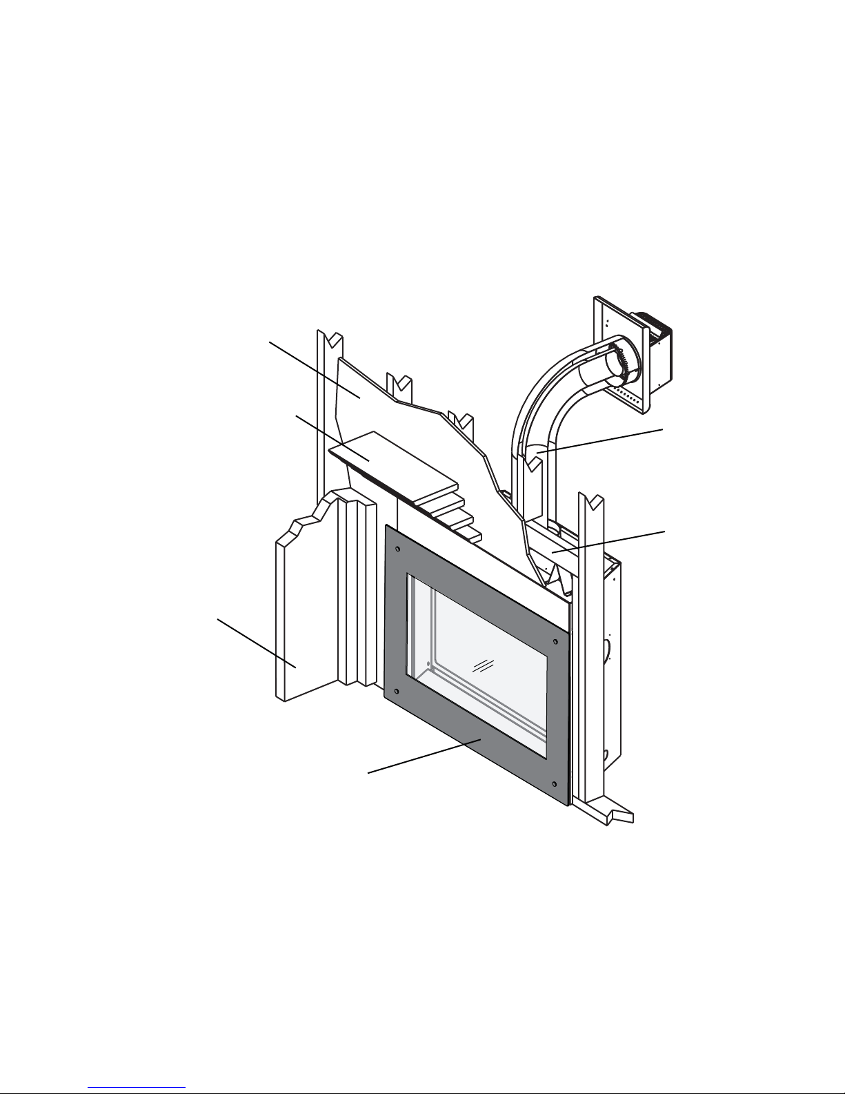
1.0 INSTALLATION OVERVIEW
See the sections “MINIMUM
ENCLOSURE CLEARANCES”
for drywall (or other
combustible material)
See the section “MINIMUM
MANTEL AND ENCLOSURE
CLEARANCES”
See the section
“VENTING” and
“INSTALLATION”
See the section
“FRAMING”
See the section
“INSTALLATION FRAMING”
Side
Wall
See the section “GD36M GLASS
FRONT INSTALLATION /
REMOVAL”
W415-0899 / 06.01.10

4
2.0 INTRODUCTION
• THIS APPLIANCE IS HOT WHEN OPERATED AND CAN CAUSE SEVERE BURNS IF CONTACTED.
• Do not operate appliance before reading and understanding operating instructions. Failure to operate
appliance according to operating instructions could cause fi re or injury.
• Risk of fi re or asphyxiation do not operate appliance with fi xed glass removed.
• Do not connect 110 volts to the control valve.
• Risk of burns. The appliance should be turned off and cooled before servicing.
• Do not install damaged, incomplete or substitute components.
• Risk of cuts and abrasions. Wear protective gloves and safety glasses during installation. Sheet metal
edges may be sharp.
• Do not burn wood or other materials in this appliance.
• Young children should be carefully supervised when they are in the same room as the appliance.
Toddlers, young children and others may be susceptible to accidental contact burns. A physical barrier
is recommended if there are at risk individuals in the house. To restrict access to an appliance or stove,
install an adjustable safety gate to keep toddlers, young children and other at risk individuals out of the
room and away from hot surfaces.
• Clothing or other fl ammable material should not be placed on or near the appliance.
• Due to high temperatures, the appliance should be located out of traffi c and away from furniture and
draperies.
• Ensure you have incorporated adequate safety measure to protect infants/toddlers from touching hot
surfaces.
• Even after the appliance is out, the glass and/or screen will remain hot for an extended period of time.
• Check with your local hearth specialty dealer for safety screens and hearth guards to protect children
from hot surfaces. These screens and guards must be fastened to the fl oor.
• Any safety screen or guard removed for servicing must be replaced prior to operating the appliance.
• It is imperative that the control compartments, burners and circulating blower and its passageway in the
appliance and venting system are kept clean. The appliance and its venting system should be inspected
before use and at least annually by a qualifi ed service person. More frequent cleaning may be required
due to excessive lint from carpeting, bedding material, etc. The appliance area must be kept clear and
free from combustible materials, gasoline and other fl ammable vapors and liquids.
• Under no circumstances should this appliance be modifi ed.
• This appliance must not be connected to a chimney fl ue pipe serving a separate solid fuel burning
appliance.
• Do not use this appliance if any part has been under water. Immediately call a qualifi ed service
technician to inspect the appliance and to replace any part of the control system and any gas control
which has been under water.
• Do not operate the appliance with the glass door removed, cracked or broken. Replacement of the glass
should be done by a licensed or qualifi ed service person.
• Do not strike or slam shut the appliance glass door.
• This appliance uses and requires a fast acting thermocouple. Replace only with a fast acting
thermocouple supplied by Wolf Steel Ltd.
• Pressure relief doors must be kept closed while the appliance is operating to prevent exhaust fumes
containing carbon monoxide, from entering into the home. Temperatures of the exhaust escaping
through these openings can also cause the surrounding combustible materials to overheat and catch
fi re.
• Only doors / optional fronts certifi ed with the unit are to be installed on the appliance.
• Keep the packaging material out of reach of children and dispose of the material in a safe manner. As
with all plastic bags, these are not toys and should be kept away from children and infants.
• As with any combustion appliance, we recommend having your appliance regularly inspected and
serviced as well as having a Carbon Monoxide Detector installed in the same area to defend you and
your family against Carbon Monoxide.
• Ensure clearances to combustibles are maintained when building a mantel or shelves above the
appliance. Elevated temperatures can cause melting, deformation, discolouration or premature failure of
T.V. or other electronic components.
!
WARNING
3.1A
W415-0899 / 06.01.10
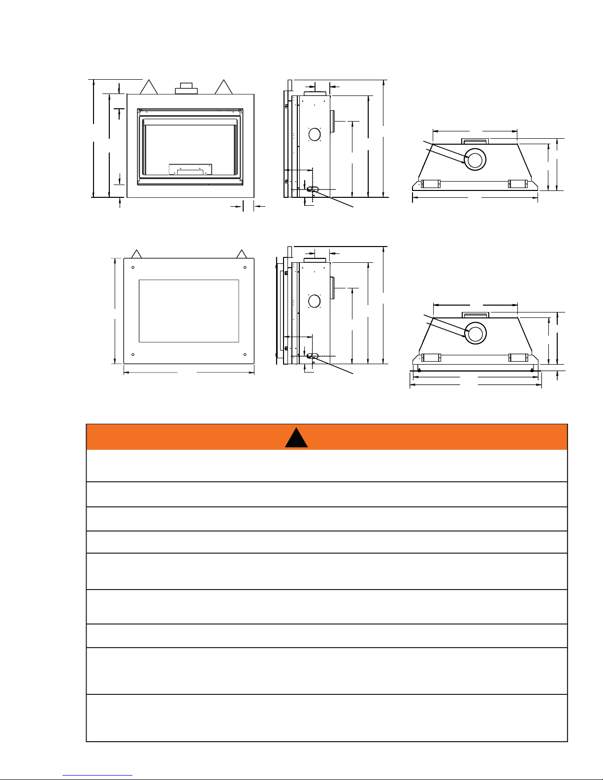
2.1 DIMENSIONS
2.1.1 BGD36CF / BGD36CFG
ǩ”
5
5”
38 ½”
34”
4 ǩ”
2.1.2 GD36M
34”
42”
2.2 GENERAL INSTRUCTIONS
3 ǫ”
8”
ELECTRICAL INLET
ELECTRICAL INLET
3”
LEFT SIDE
5”
8”
3”
LEFT SIDE
24 ¼”
24 ¼”
GAS
INLET
GAS
INLET
33”
33”
38 ½”
38 ½”
4" DIA.
7" DIA.
4" DIA.
7" DIA.
27”
17”
15”
40”
27”
17”
15”
2”
40”
42”
!
WARNING
ALWAYS LIGHT THE PILOT WHETHER FOR THE FIRST TIME OR IF THE GAS SUPPLY HAS RAN OUT,
WITH THE GLASS DOOR OPENED OR REMOVED.
PROVIDE ADEQUATE CLEARANCE FOR SERVICING AND OPERATING THE APPLIANCE.
PROVIDE ADEQUA TE VENTILA TION.
NEVER OBSTRUCT THE FRONT OPENING OF THE APPLIANCE.
OBJECTS PLACED IN FRONT OF THE APPLIANCE MUST BE KEPT A MINIMUM OF 48” FROM THE
FRONT FACE OF THE UNIT.
SURFACES AROUND AND ESPECIALLY ABOVE THE APPLIANCE CAN BECOME HOT. AVOID CONTACT
WHEN THE APPLIANCE IS OPERATING.
FIRE RISK. EXPLOSION HAZARD.
HIGH PRESSURE WILL DAMAGE VALVE. DISCONNECT GAS SUPPLY PIPING BEFORE PRESSURE TESTING
GAS LINE AT TEST PRESSURES ABOVE 1/2 PSIG. CLOSE THE MANUAL SHUT-OFF VALVE BEFORE
PRESSURE TESTING GAS LINE AT TEST PRESSURES EQUAL TO OR LESS THAN 1/2 PSIG.
USE ONLY WOLF STEEL APPROVED OPTIONAL ACCESSORIES AND REPLACEMENT PARTS WITH THIS APPLIANCE.
USING NON-LISTED ACCESSORIES (BLOWERS, DOORS, LOUVRES, TRIMS, GAS COMPONENTS, VENTING
COMPONENTS, ETC.) COULD RESULT IN A SAFETY HAZARD AND WILL VOID THE WARRANTY AND CERTIFICATION.
W415-0899 / 06.01.10
6
A
A
THIS GAS APPLIANCE SHOULD BE INSTALLED AND SERVICED BY A QUALIFIED INSTALLER to
conform with local codes. Installation practices vary from region to region and it is important to know the
specifi cs that apply to your area, for example in Massachusetts State:
• This product must be installed by a licensed plumber or gas fi tter when installed within the commonwealth
of Massachusetts.
• The appliance damper must be removed or welded in the open position prior to installation of a appliance
insert or gas log.
• The appliance off valve must be a “T” handle gas cock.
• The fl exible connector must not be longer than 36 inches.
• A Carbon Monoxide detector is required in all rooms containing gas fi red appliances.
• The appliance is not approved for installation in a bedroom or bathroom unless the unit is a direct vent
sealed combustion product.
The installation must conform with local codes or, in
absence of local codes, the National Gas and Propane
Installation Code CSA B149.1 in Canada, or the National
Fuel Gas Code, ANSI Z223.1 / NFPA 54 in the United
States. Suitable for mobile home installation if installed in
accordance with the current standard CAN/CSA Z240MH
Series, for gas equipped mobile homes, in Canada or
NSI Z223.1 and NFPA 54 in the United States.
www.ncertied.org
s long as the required clearance to combustibles is
maintained, the most desirable and benefi cial location for an appliance is in the center of a building, thereby
allowing the most effi cient use of the heat created. The location of windows, doors and the traffi c fl ow in the
room where the appliance is to be located should be considered. If possible, you should choose a location
where the vent will pass through the house without cutting a fl oor or roof joist.
If the appliance is installed directly on carpeting, vinyl tile or other combustible material other than wood
fl ooring, the appliance shall be installed on a metal or wood panel extending the full width and depth.
If the optional fan or blower is installed, the junction box must be electrically connected and grounded in
accordance with local codes, use the current CSA C22.1 Canadian Electrical Code in Canada or the ANSI/
NFPA 70 National Electrical code in the United States.
All sections of this manual with BGD36CF(G) are common to BGD36CF, BGD36CFG and GD36M. All sections
with BGD36CFG / GD36M are common to both the BGD36CFG and GD36M
We suggest that our gas
hearth products be installed
and serviced by professionals
who are certied in the U.S.
by the National Fireplace
Institute
®
(NFI) as NFI Gas
Specialists
4.1
W415-0899 / 06.01.10
2.3 GENERAL INFORMATION
FOR YOUR SATISFACTION, THIS APPLIANCE HAS BEEN TEST-FIRED TO ASSURE ITS OPERATION AND
QUALITY!
Altitude (FT) 0-4,500 0-4500
Max. Input (BTU/HR) 17,000 17,000
Max. Output Steady State (BTU/HR) 10,900 10,900
Effi ciency (w/the fan on) 64% 64%
A.F.U.E. (Annual Fuel Utilization Effi ciency) 53% 53%
Min. Inlet Gas Supply Pressure 4.5" Water Column 11" Water Column
Max. Inlet Gas Supply Pressure 7" Water Column 13" Water Column
Manifold Pressure (Under Flow Conditions) 3.5" Water Column 10" Water Column
This appliance is approved for bathroom, bedroom and bed-sitting room installations and is suitable for mobile
home installation.
7
APPLIANCE
NG LP
No external electricity (110 volts or 24 volts) is required for the gas system operation.
Expansion / contraction noises during heating up and cooling down cycles are normal and are to be expected.
Use only accessories designed for and listed with your specifi c appliance.
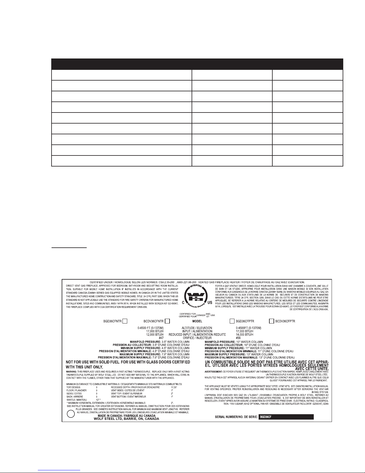
2.4 RATING PLATE INFORMATION
INSTALLER: It is your responsibility to check off the appropriate box on the rating plate according to
the model, venting and gas type of the appliance.
For rating plate location, see “INSTALLATION OVERVIEW” section.
99
REFERENCE # W/N 15538
W385-0342 / F
W415-0899 / 06.01.10

8
3.0 VENTING
!
WARNING
RISK OF FIRE, MAINTAIN SPECIFIED AIR SPACE CLEARANCES TO VENT PIPE AND APPLIANCE.
IF VENTING IS INCLUDED WITH SPACERS THE VENT SYSTEM MUST BE SUPPORTED EVERY 3 FEET
FOR BOTH VERTICAL AND HORIZONTAL RUNS. USE SUPPORTS OR EQUIVALENT
NON-COMBUSTIBLE STRAPPING TO MAINTAIN THE REQUIRED CLEARANCE FROM
COMBUSTIBLES. USE WOLF STEEL LTD. SUPPORT RING ASSEMBLY W010-0370 OR EQUIVALENT
NON-COMBUSTIBLE STRAPPING TO MAINTAIN THE MINIMUM CLEARANCE TO COMBUSTIBLES
FOR BOTH VERTICAL AND HORIZONTAL RUNS. SPACERS ARE ATTACHED TO THE INNER PIPE AT
PREDETERMINED INTERVALS TO MAINTAIN AN EVEN AIR GAP TO THE OUTER PIPE. THIS GAP IS
REQUIRED FOR SAFE OPERATION. A SPACER IS REQUIRED AT THE START, MIDDLE AND END OF
EACH ELBOW TO ENSURE THIS GAP IS MAINTAINED. THESE SPACERS MUST NOT BE REMOVED.
THIS APPLIANCE USES A 4” EXHAUST / 7” AIR INTAKE VENT PIPE SYSTEM.
Refer to the section applicable to your installation.
For safe and proper operation of the appliance follow the venting instruction exactly. Deviation from the
minimum vertical vent length can create diffi culty in burner start-up and/or carboning. Under extreme vent
confi gurations, allow several minutes (5-15) for the fl ame to stabilize after ignition. Vent lengths that pass
through unheated spaces (attics, garages, crawl spaces) should be insulated with the insulation wrapped in
a protective sleeve to minimize condensation. Provide a means for visually checking the vent connection to
the appliance after the appliance is installed. Use a fi restop, vent pipe shield or attic insulation shield when
penetrating interior walls, fl oor or ceiling.
NOTE: If for any reason the vent air intake system is disassembled; reinstall per the instructions
provided for the initial installation.
3.1 VENTING LENGTHS AND COMPONENTS
7.1
Use only Wolf Steel, Simpson Dura-Vent, Selkirk Direct Temp, American Metal Amerivent or Metal-Fab venting
components. Minimum and maximum vent lengths, for both horizontal and vertical installations, and air terminal
locations for either system are set out in this manual and must be adhered to. For Simpson Dura-Vent, Selkirk Direct
Temp, American Metal Amerivent and Metal-Fab follow the installation procedure provided with the venting components.
A starter adaptor must be used with the following vent systems and may be purchased from the corresponding supplier:
PART 4”/7” SUPPLIER WEBSITE
Duravent W175-0053 Wolf Steel www.duravent.com
Amerivent 4DSC-N2 American Metal www.americanmetalproducts.com
Direct Temp 4DT-AAN Selkirk www.selkirkcorp.com
SuperSeal 4DNA Metal-Fab www.mtlfab.com
For Simpson Dura-Vent, Selkirk Direct Temp, American Metal Amerivent and Metal-Fab follow the installation
procedure found on the website for your venting supplier.
For vent systems that provide seals on the inner exhaust fl ue, only the outer air intake joints must be sealed using a red
high temperature silicone (RTV). This same sealant may be used on both the inner exhaust and outer intake vent pipe
joints of all other approved vent systems except for the exhaust vent pipe connection to the appliance fl ue collar which must
be sealed using the black high temperature sealant Mill Pac. High temperature sealant must be ordered separately.
When using Wolf Steel venting components, use only approved Wolf Steel rigid / fl exible components with the following
termination kits: wall terminal kit GD222, GD222R, or 1/12 to 7/12 pitch roof terminal kit GD110, 8/12 to 12/12 roof terminal
kit GD111, fl at roof terminal kit GD112 or periscope kit GD201 (for wall penetration below grade). With fl exible venting, in
conjunction with the various terminations, use either the 5 foot vent kit GD220 or the 10 foot vent kit GD330.
W415-0899 / 06.01.10
For optimum flame appearance and appliance performance, keep the vent length and number of elbows to a minimum.
The air terminal must remain unobstructed at all times. Examine the air terminal at least once a year to verify that
it is unobstructed and undamaged.
Rigid and fl exible venting systems must not be combined. Different venting manufacturer components must not
be combined.
These vent kits allow for either horizontal or vertical venting of the appliance. The maximum allowable horizontal run is 20
feet. The maximum allowable vertical vent length is 40 feet. The maximum number of vent connections is two horizontally
or three vertically (excluding the appliance and the air terminal connections) when using fl exible venting.
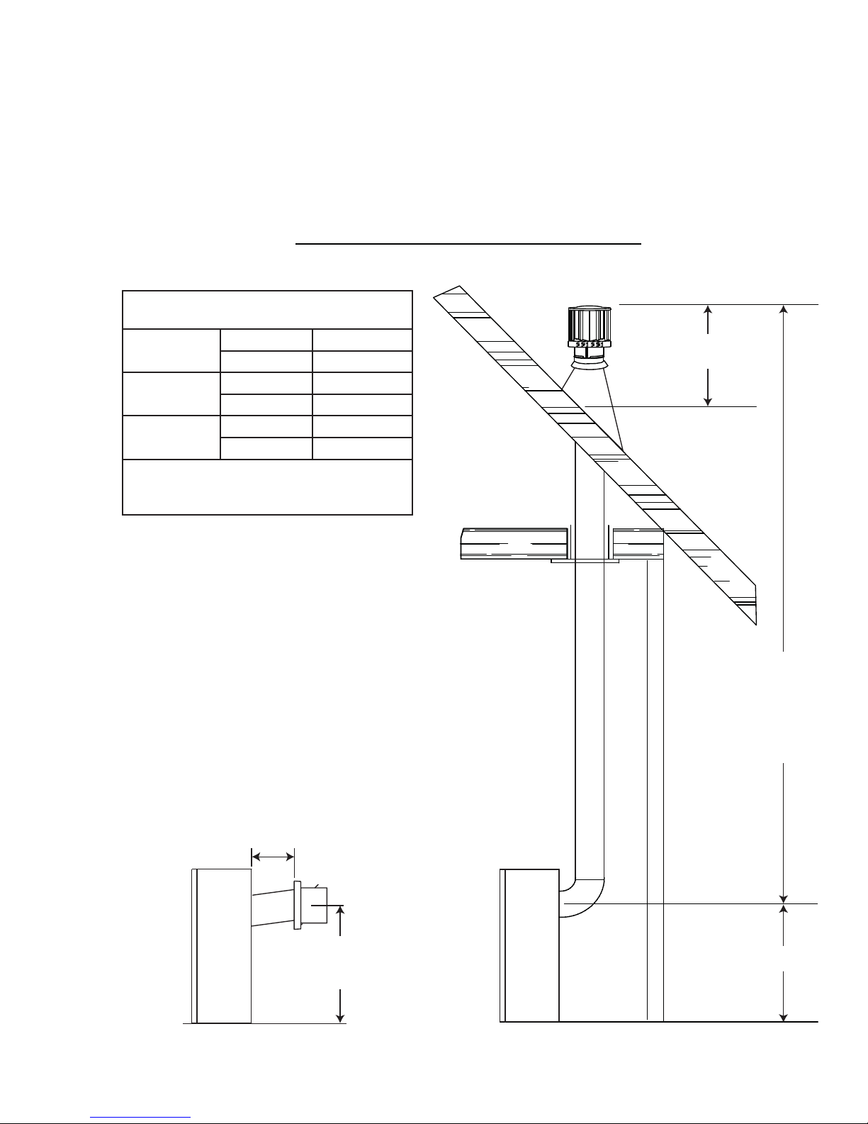
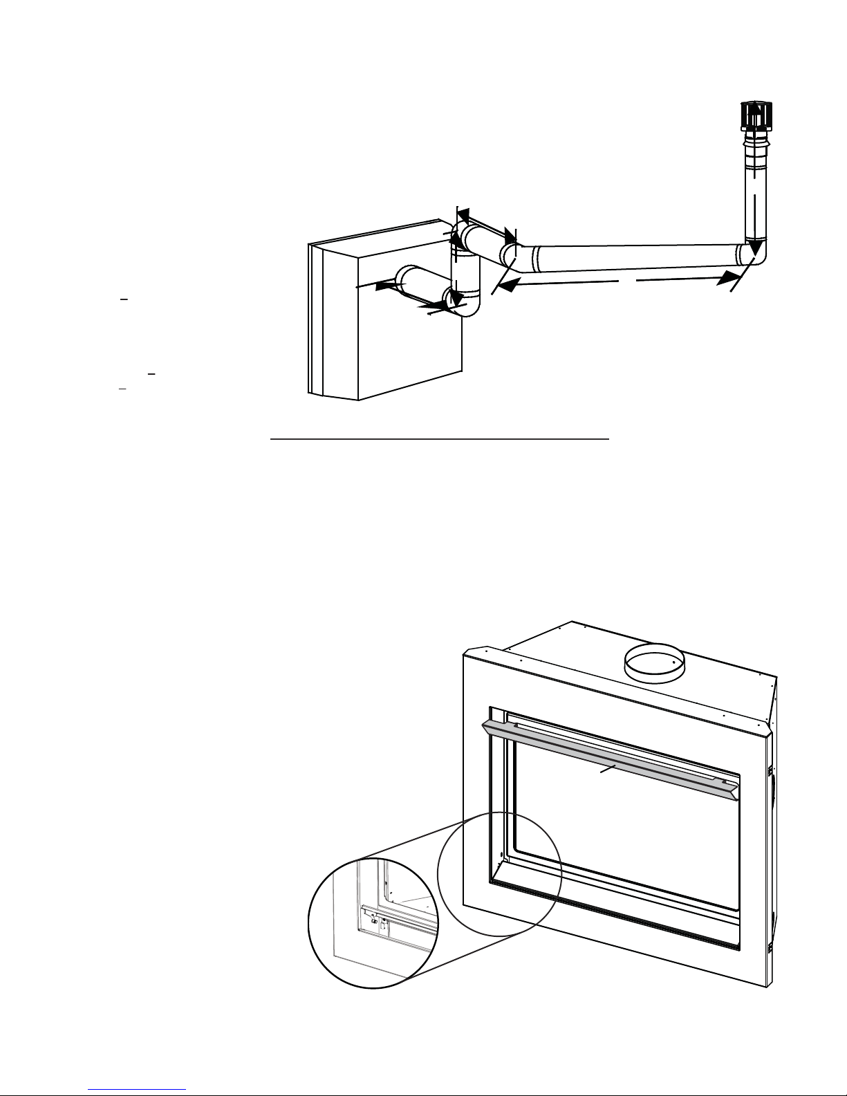
3.2 TYPICAL VENT INSTALLATIONS
REQUIRED RISE ON HORIZONTAL
VENTING
REAR VENT RIGID 0" / FT
FLEXIBLE 0" / FT
TOP VENT RIGID 0" / FT
FLEXIBLE 0" / FT
CORNER
VENT
For optimum performance, it is recommended that all horizontal runs have a 1" rise per
foot.
RIGID 0"
FLEXIBLE 6"
9
8.1
16" MINIMUM
20" MAXIMUM
* See "VENTING" section.
24 1/4"
MINIMUM
PLUS RISE*
40 FT
MAXIMUM
3 FT
MINIMUM
24 1/4"
REAR VENT
W415-0899 / 06.01.10
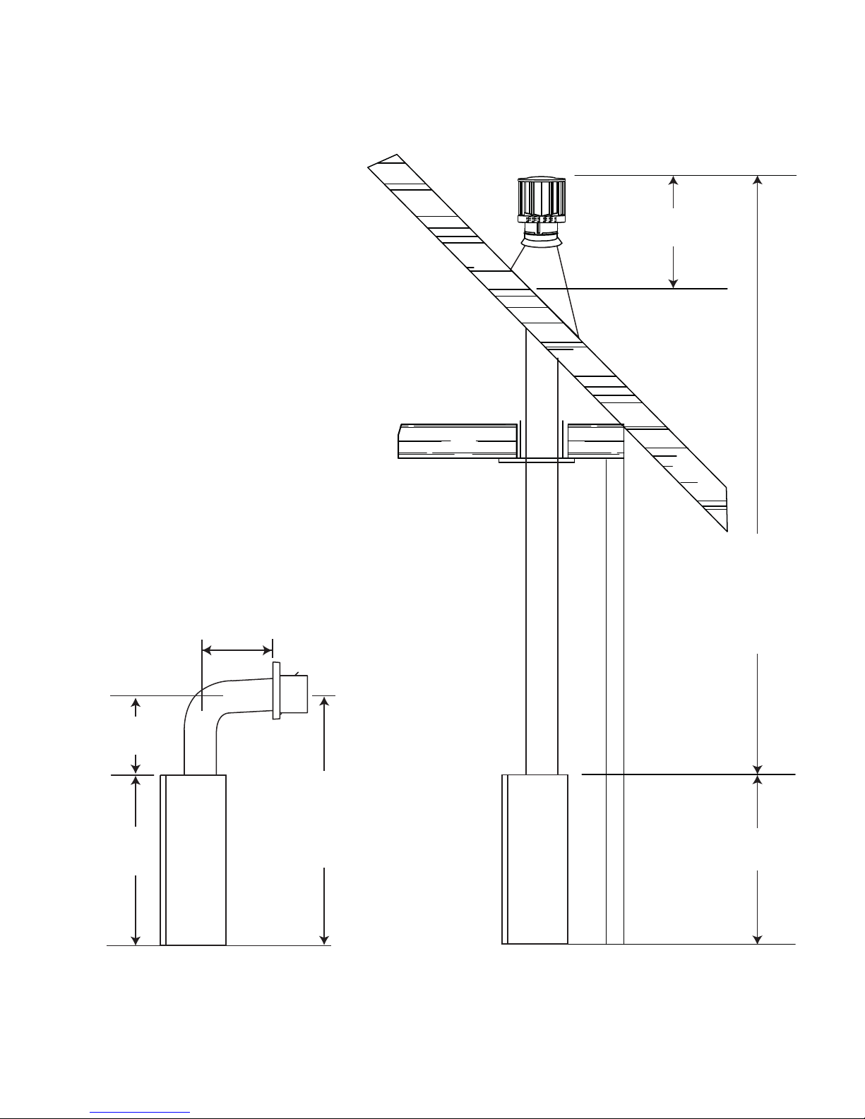
10
16" MINIMUM
10"
MINIMUM
34"
40 FT
MAXIMUM
3 FT
MINIMUM
24" MAXIMUM
42 3/8"
MINIMUM
PLUS RISE*
34"
TOP VENT
* See "VENTING" section.
W415-0899 / 06.01.10
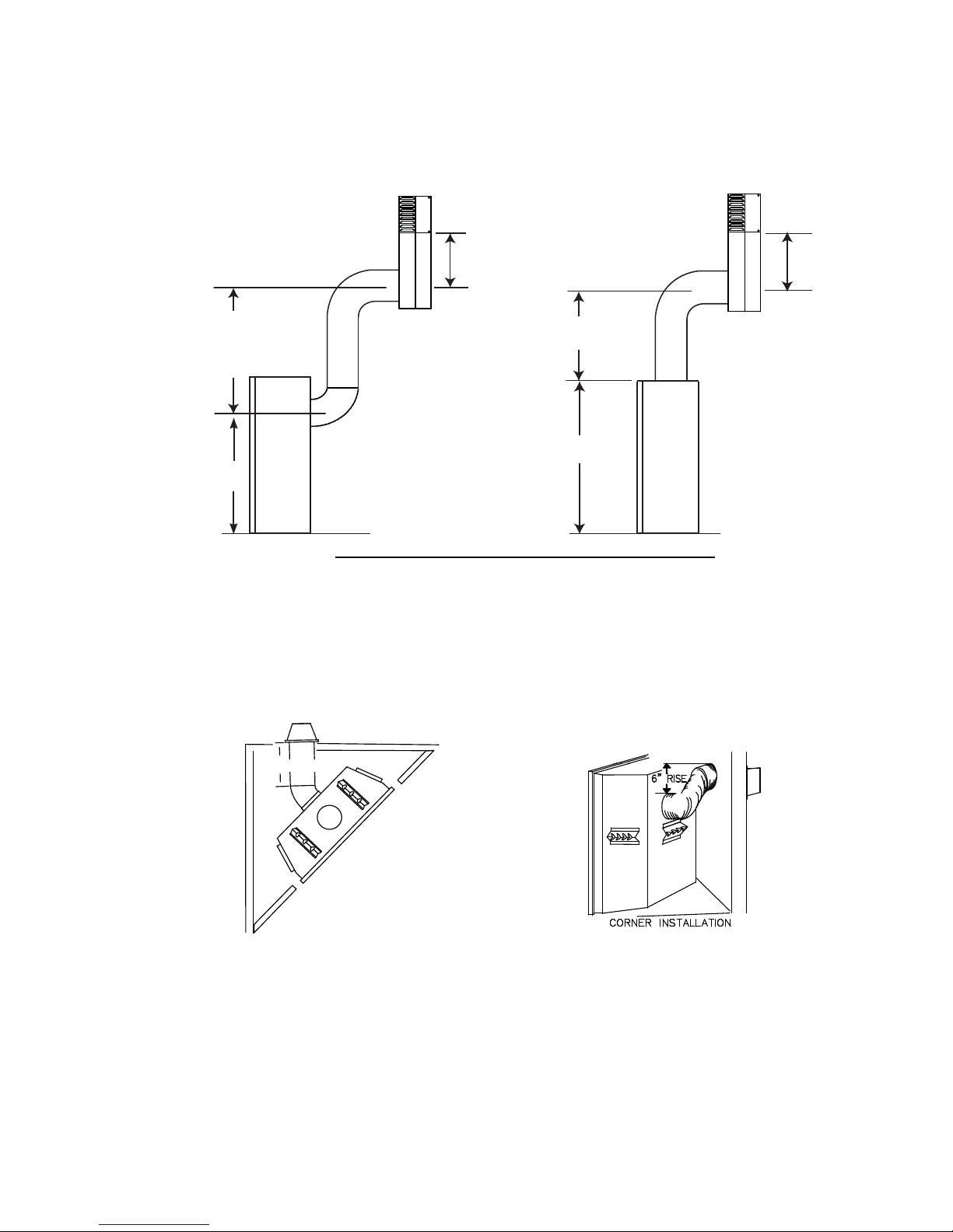
3.3 SPECIAL VENT INSTALLATIONS
3.3.1 PERISCOPE TERMINATION
Use the periscope kit to locate the air termination above grade. The periscope must be installed so that when
fi nal grading is completed, the bottom air slot is located a minimum 12” above grade. The maximum allowable
vent length is 10’.
11
30" MIN
24 1/4"
3.3.2 CORNER TERMINATION
The maximum vent length for a corner installation is 20" of horizontal run, in addition to the 45° offset. In this
case zero rise is acceptable when using rigid. Flexible venting must maintain a 6" rise.
12"
MIN TO
GRADE
12"
MIN TO
GRADE
30" MIN
34"
9.4
20" MAX
W415-0899 / 06.01.10
12
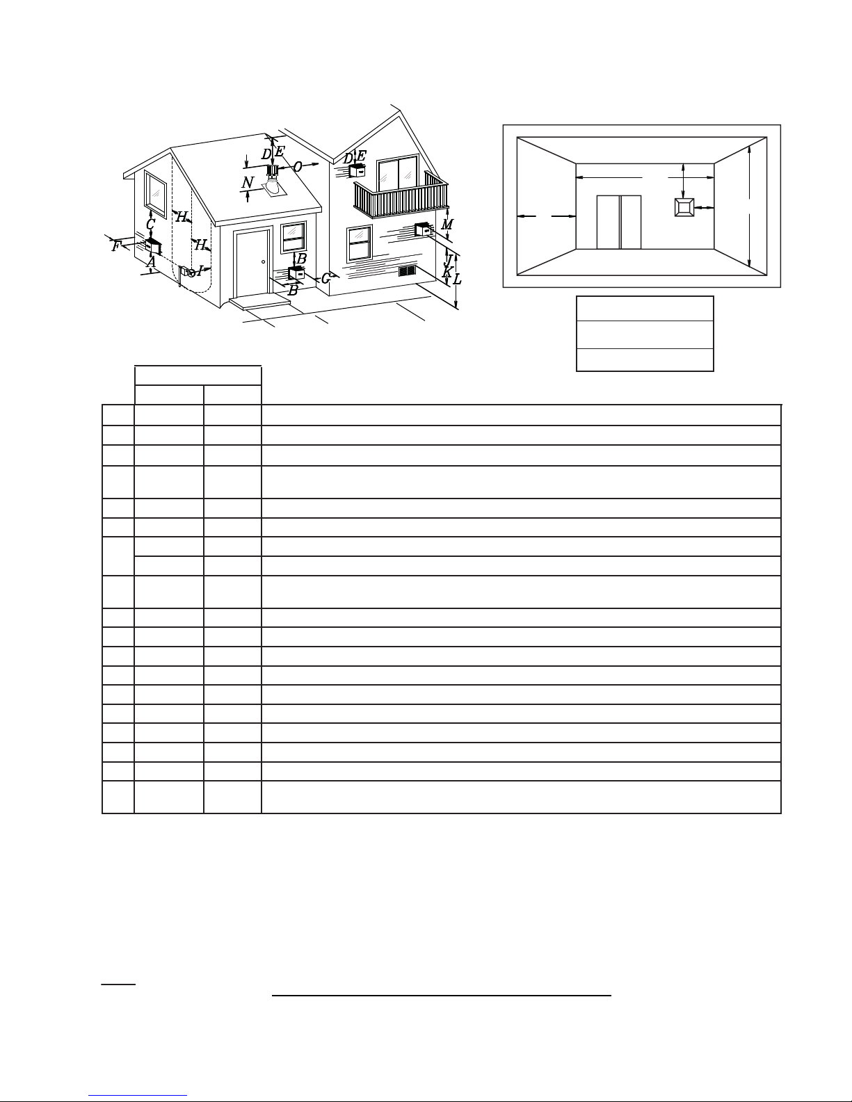
3.4 MINIMUM AIR TERMINAL LOCATION CLEARANCES
COVERED BALCONY APPLICATIONS
Q
M
R
G
P
Q
R
R
MIN
MAX
MAX
= 3 feet
= 2 x
Q
feet
ACTUAL
INSTALLATIONS
CANADA U.S.A.
A 12” 12” Clearance above grade, veranda porch, deck or balcony.
B 12”
Δ
9”
Δ
Clearance to windows or doors that open.
C 12” * 12” * Clearance to permanently closed windows.
D 18” ** 18” **
Vertical clearance to ventilated soffi ts located above the terminal within a horizontal distance of 2’ from
the centerline of the terminal.
E 12” ** 12” ** Clearance to unventilated soffi t.
F 0” 0” Clearance to an outside corner wall.
G
H 3’ 3’ ****
0” *** 0” *** Clearance to an inside non-combustible corner wall or protruding non-combustible obstructions (chimney, etc.).
2” *** 2” *** Clearance to an inside combustible corner wall or protruding combustible obstructions (vent chase, etc.).
Clearance to each side of the centerline extended above the meter / regulator assembly to a maximum
vertical distance of 15’.
I 3’ 3’ **** Clearance to a service regulator vent outlet.
J 12” 9” Clearance to a non-mechanical air supply inlet to the building or a combustion air inlet to any other appliance.
K 6’ 3’ † Clearance to a mechanical air supply inlet.
L 7’ ‡ 7’ **** Clearance above a paved sidewalk or paved driveway located on public property.
M 12” †† 12” **** Clearance under a veranda, porch, deck or balcony.
N 16” 16” Clearance above the roof.
O 2’ †* 2’ †* Clearance from an adjacent wall including neighbouring buildings.
P 8’ 8’ Roof must be non-combustible without openings.
Q 3’ 3’ See chart for wider wall dimensions.
R 6’ 6’
The terminal shall not be located less than 6 feet under a window that opens on a horizontal plane in a structure with three walls and a roof.
Δ
* Recommended to prevent condensation on windows and thermal breakage
** it is recommended to use a heat shield and to maximize the distance to vinyl clad soffi ts.
*** The periscope requires a minimum 18 inches clearance from an inside corner.
**** This is a recommended distance. For additional requirements check local codes.
† 3 feet above if within 10 feet horizontally.
‡ A vent shall not terminate directly above a sidewalk or paved driveway that is located between two single family dwellings and serves both dwellings.
†† Permitted only if the veranda, porch, or deck is fully open on a minimum of two sides beneath the fl oor.
†* Recommended to prevent recirculation of exhaust products. For additional requirements check local codes.
See chart for deeper wall dimensions. The terminal shall not be installed on any wall that has an opening between the terminal and the open side of the structure.
NOTE: Clearances are in accordance with local installation codes and the requirements of the gas supplier.
12.1A
W415-0899 / 06.01.10
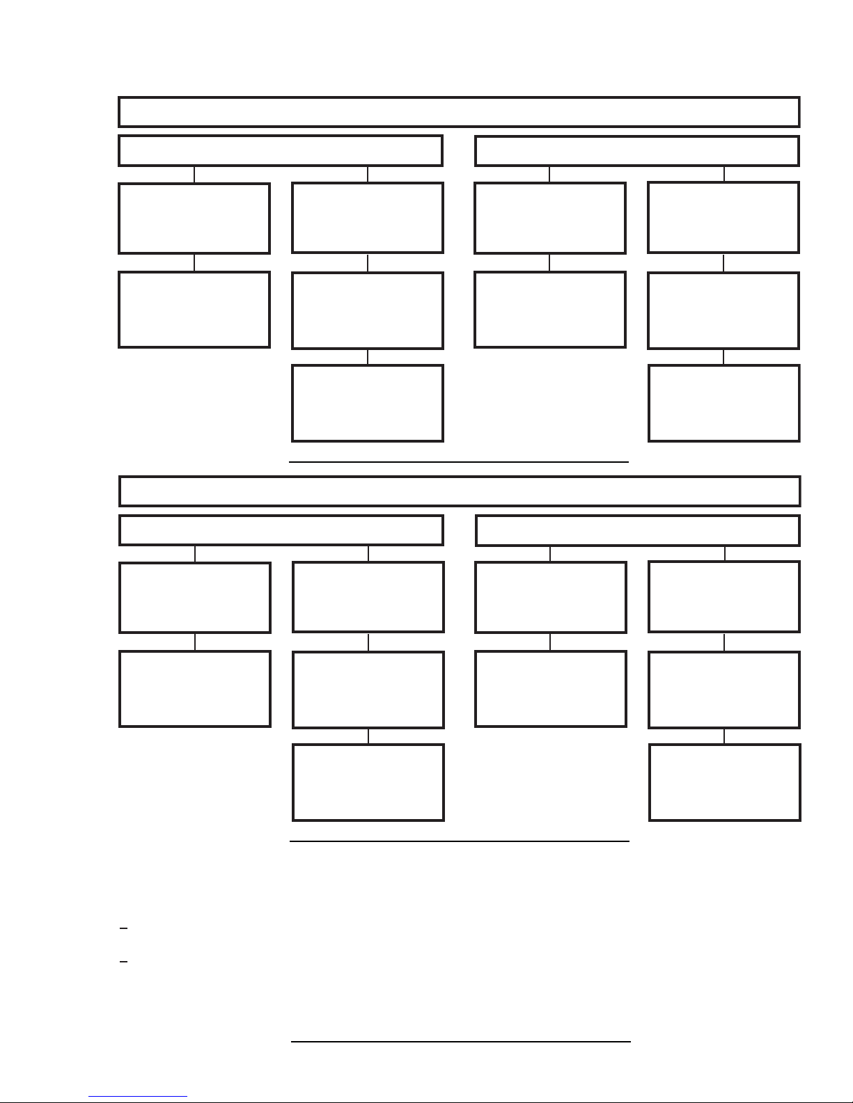
3.5 VENT APPLICATION FLOW CHART
13
TOP EXIT
Horizontal Termination
Vertical rise is equal
to or greater than
the horizontal run
Horizontal run +
vertical rise to
maximum of 40 feet
Horizontal Termination
Vertical rise is less
than horizontal run
Horizontal run +
vertical rise to
maximum of 24.75
feet
4.2 times the
vertical rise equal to
or greater than the
horizontal run
REAR EXIT
Vertical Termination
Vertical rise is equal
to or greater than
the horizontal run
Horizontal run +
vertical rise to
maximum of 40 feet
Vertical Termination
Vertical rise is less
than horizontal run
Horizontal run +
vertical rise to
maximum of 40 feet
3 times the vertical
rise equal to or
greater than the
horizontal run
13.1
Vertical rise is equal
to or greater than
the horizontal run
Horizontal run +
vertical rise to
maximum of 40 feet
3.6 DEFINITIONS
For the following symbols used in the venting calculations and examples are:
> - greater than
> - equal to or greater than
< - less than
< - equal to or less than
HT - total of both horizontal vent lengths (Hr) and offsets (Ho) in feet
HR - combined horizontal vent lengths in feet
HO - offset factor: .03 (total degrees of offset - 90°*) in feet
VT - combined vertical vent lengths in feet
Vertical rise is less
than horizontal run
Horizontal run +
vertical rise to
maximum of 24.75
feet
3.5 times the
vertical rise equal to
or greater than the
horizontal run
Vertical rise is equal
to or greater than
the horizontal run
Horizontal run +
vertical rise to
maximum of 40 feet
Vertical rise is less
than horizontal run
Horizontal run +
vertical rise to
maximum of 40 feet
3 times the vertical
rise equal to or
greater than the
horizontal run
13.2
14.1
W415-0899 / 06.01.10
14
3.7 ELBOW VENT LENGTH VALUES
FEET INCHES
1° 0.03 0.5
15° 0.45 6.0
30° 0.9 11.0
45° 1.35 16.0
90°* 2.7 32.0
* The fi rst 90° offset has a zero value and is shown in the formula as - 90°
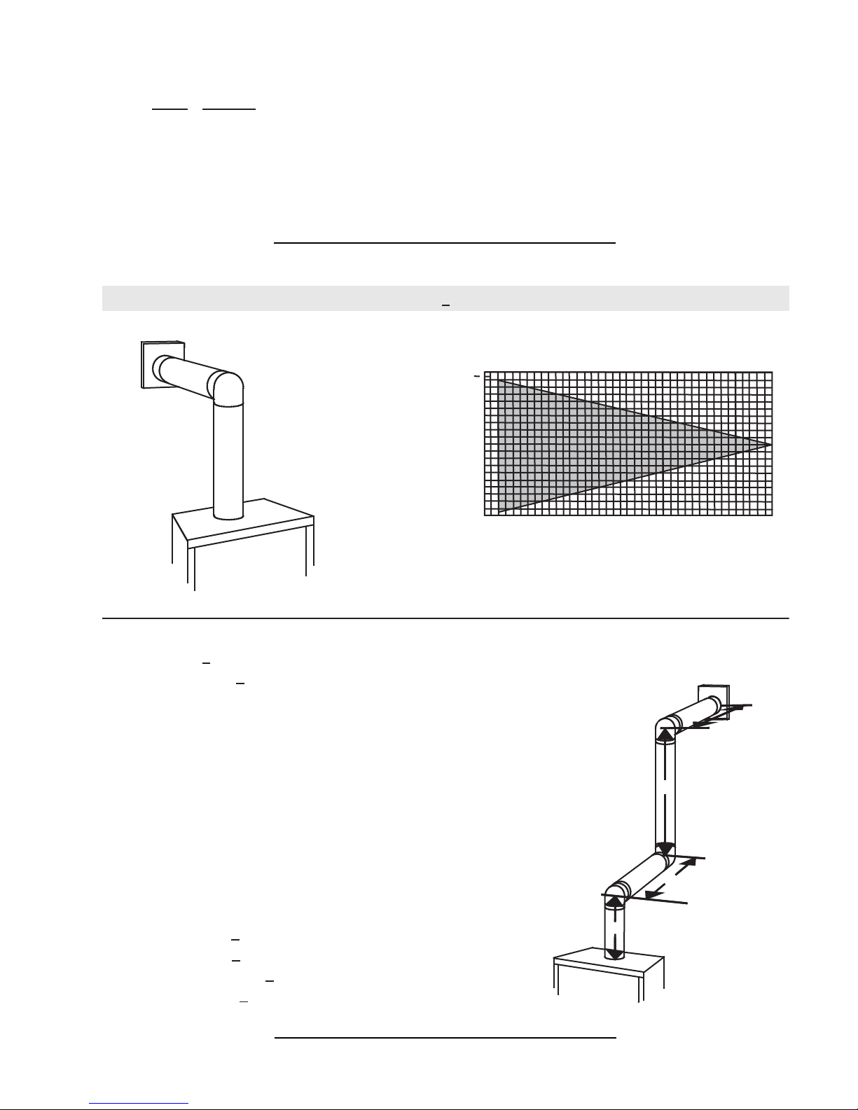
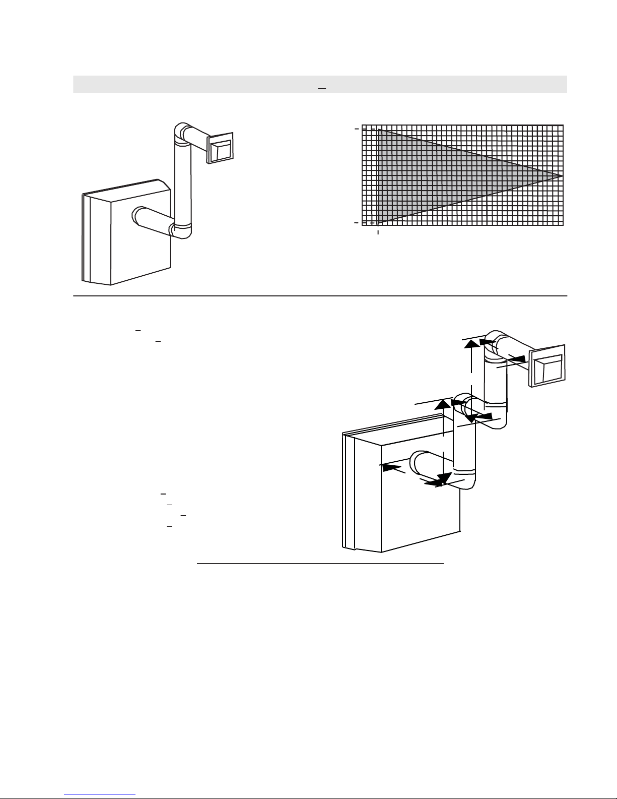
3.8 TOP EXIT HORIZONTAL TERMINATION
(HT) < (VT)
15.1
Simple venting confi guration (only one 90° elbow)
See graph to determine the required vertical
rise VT for the required horizontal run HT.
40
39
30
REQUIRED
VERTICAL
20
RISE IN
FEET VT
10
0
2.5 5 7.5 10 12.5 15
HORIZONTAL VENT RUN PLUS OFFSET IN
FEET H
T
The shaded area within the lines represents
acceptable values for HT and V
For vent confi gurations requiring more than one 90° elbow, the following formulas apply:
Formula 1: HT < V
T
Formula 2: HT + VT < 40 feet
Example 1:
V
= 3 FT
1
V
= 8 FT
2
= V1 + V
V
T
H
= 2.5 FT
1
H
= 2 FT
2
HR = H1 + H
H
= .03 (three 90° elbows - 90°) = .03 (270° - 90°) = 5.4 FT
O
= 3 FT + 8 FT = 11 FT
2
= 2.5 + 2 = 4.5 FT
2
HT = HR + HO = 4.5 + 5.4 = 9.9 FT
HT + V
= 9.9 + 11 = 20.9 FT
T
90°
90°
90°
V
2
H
1
17.5 20
T
H
2
Formula 1: HT < V
T
9.9 < 11
Formula 2: HT + VT < 40 FT
20.9 < 40
Since both formulas are met, this vent confi guration is acceptable.
W415-0899 / 06.01.10
V
1
16.1A
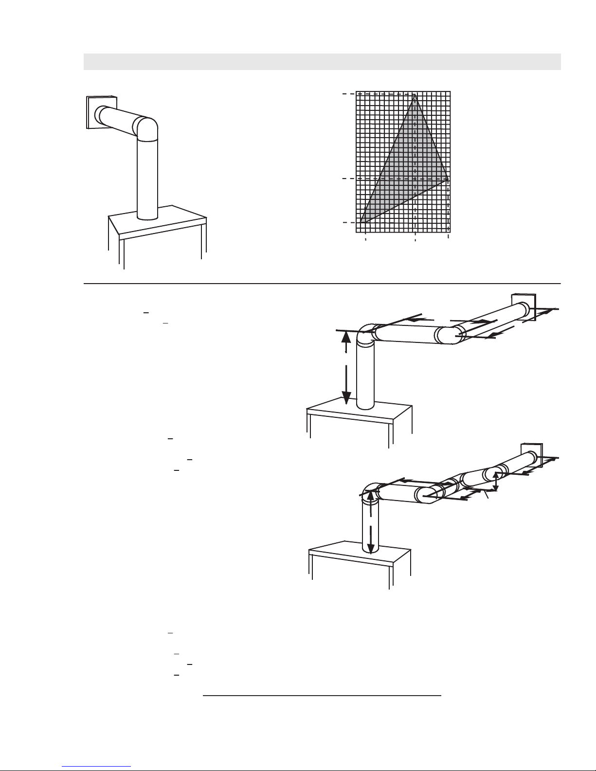
15
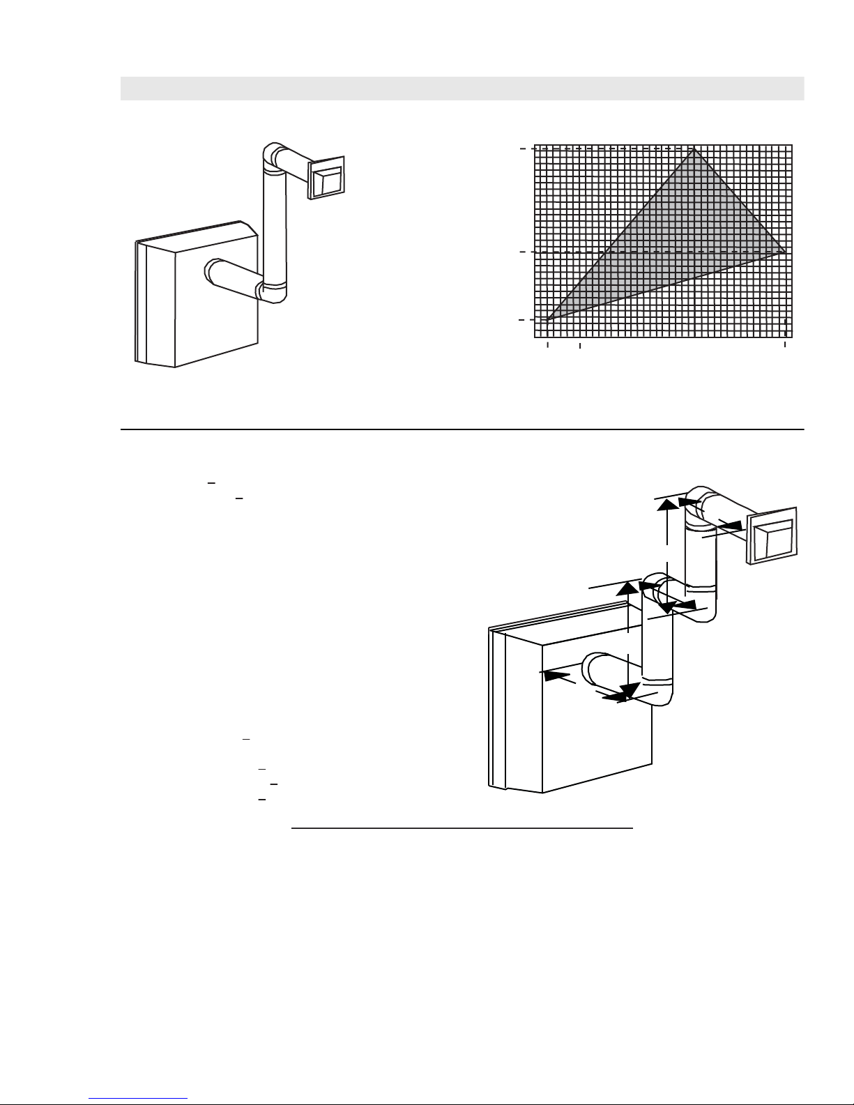
Simple venting configuration
(only one 90° elbow)
(HT) > (VT)
See graph to determine the required vertical rise VT for the required horizontal run HT.
147”
150
REQUIRED
VERTICAL
100
RISE IN
INCHES VT
57”
50
10”
0
515
2’
10
12.5’
19.5’
HORIZONTAL VENT RUN PLUS OFFSET IN FEET H
The shaded area within the lines represents acceptable values for H
For vent configurations requiring more than one 90° elbow, the following formulas apply:
Formula 1: H
Formula 2: HT + V
< 4.2 V
T
T
T
< 24.75 feet
90°
H
1
Example 2:
V
= VT = 6 FT
1
H
= 3 FT
1
H
= 5 FT
2
H
= H
+ H
R
H
= .03 (two 90° elbows - 90°) = .03 (180° - 90°) = 2.7 FT
O
H
= H
T
H
+ V
T
= 3 + 5 = 8 FT
1
2
+ H
= 8 + 2.7 = 10.7 FT
R
O
= 10.7 + 6 = 16.7 FT
T
V
1
20
90°
T
T
and VT
H
2
Formula 1: HT < 4.2 V
4.2 VT = 4.2 x 6 = 25.2 FT
Formula 2: HT + V
16.7 < 24.75
T
< 24.75 FT
T
Since both formulas are met, this vent configuration is acceptable.
Example 3:
V
= 4 FT
1
V
= 1.5 FT
2
V
= V
+ V
T
H
= 2 FT
1
= 1 FT
H
2
H
= 1 FT
3
H
= 1.5 FT
4
H
= H
R
H
= .03 (four 90° elbows - 90°) = .03 (360° - 90°) = 8.1 FT
O
= H
H
T
H
+ V
T
Formula 1: HT < 4.2 V
4.2 VT = 4.2 x 5.5 = 23.1 FT
= 4 + 1.5 = 5.5 FT
1
2
+ H2 + H
1
+ H
R
= 13.6 + 5.5 = 19.1 FT
T
+ H4 = 2 + 1 + 1 + 1.5 = 5.5 FT
3
= 5.5 + 8.1 = 13.6 FT
O
T
13.6 < 23.1
Formula 2: HT + V
19.1 < 24.75
< 24.75 FT
T
Since both formulas are met, this vent configuration is acceptable.
90°
90°
90°
H
1
90°
V
1
V
H
H
2
3
16.2_3A
H
4
2
W415-0899 / 06.01.10
16
3.9 REAR EXIT HORIZONTAL TERMINATION
Simple venting configuration
(only two 90° elbows)
(HT) < (VT)
See graph to determine the required vertical rise V
38.3
horizontal run HT.
40
30
REQUIRED
VERTICAL
RISE IN
FEET V
20
T
10
1.6
0
2.5 5 7.5 10 12.5 15
1.6
HORIZONTAL VENT RUN PLUS OFFSET IN FEET H
The shaded area within the lines represents acceptable values for H
and HT
For vent configurations requiring more than two 90° elbows, the following formulas apply:
Formula 1: H
Formula 2: HT + V
< V
T
T
< 40 feet
T
Example 4:
V
= 9 FT
1
V
= 6 FT
2
V
= V
+ V
T
H
= 3 FT
1
H
= 2 FT
2
H
= 1.5 FT
3
H
= H
R
H
= .03 (four 90° elbows - 90°) = .03 (360° - 90°) = 8.1 FT
O
H
= H
T
H
+ V
T
Formula 1: HT < V
14.6 < 15
Formula 2: HT + V
29.6 < 40
= 9 + 6 = 15 FT
1
2
+ H2 + H
1
+ H
R
= 14.6 + 15 = 29.6 FT
T
= 3 + 2 + 1.5 = 6.5 FT
3
= 6.5 + 8.1 = 14.6 FT
O
T
< 40 FT
T
H
1
90°
V
1
Since both formulas are met, this vent configuration is acceptable.
for the required
T
90°
H
V
2
H
2
90°
3
90°
17.5 20
T
T
W415-0899 / 06.01.10
16.3
17
(HT) > (VT)
Simple venting configuration
(only two 90° elbows)
See graph to determine the required vertical rise V
required horizontal run H
150
147
REQUIRED
VERTICAL
100
RISE IN
INCHES V
T
66
50
12
0
2.5 5 7.5 10 12.5 15 17.5 20
3.5
1
HORIZONTAL VENT RUN PLUS OFFSET IN FEET H
The shaded area within the lines represents acceptable
values for H
T
For vent configurations requiring more than two 90° elbows, the following formulas apply:
Formula 1: H
Formula 2: HT + V
< 3.5V
T
T
< 24.75 feet
T
Example 4:
V
= 4 FT
1
V
= 1.5 FT
2
V
= V
+ V
T
H
= 2 FT
1
H
= 1 FT
2
H
= 1 FT
3
H
= 1.5 FT
4
H
= H
R
H
= .03 (four 90° elbows + one 45° elbow - 90°)
O
= .03 (90 + 90 + 90 + 90 + 45 - 90) = 9.45 FT
H
= H
T
H
+ V
T
Formula 1: HT < 3.5V
3.5VT = 3.5 x 5.5 = 19.25 FT
= 4 + 1.5 = 5.5 FT
1
2
+ H2 + H3 + H
1
+ H
= 5.5 + 9.45 = 14.95 FT
R
O
= 14.95 + 5.5 = 20.45 FT
T
= 2 + 1 + 1 + 1.5 = 5.5 FT
4
T
14.95 < 19.25
Formula 2: HT + V
20.45 < 24.75
< 24.75 FT
T
H
1
90°
V
1
Since both formulas are met, this vent configuration is acceptable.
16.3_2A
and HT
90°
V
2
H
2
90°
T
H
.
3
90°
for the
T
19.25
T
W415-0899 / 06.01.10
18
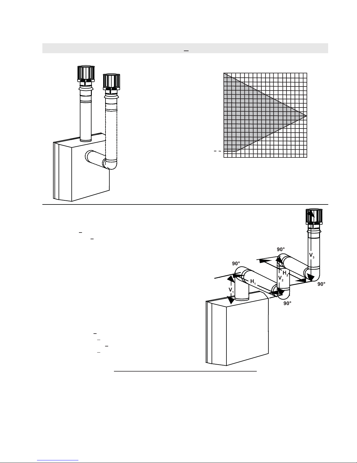
3.10 TOP OR REAR EXIT VERTICAL TERMINATION
(HT) < (VT)
Simple venting configurations.
See graph to determine the required vertical rise V
required horizontal run H
40
30
T
REQUIRED
VERTICAL
20
RISE IN
FEET VT
10
3
0
5101520
HORIZONTAL VENT RUN PLUS OFFSET IN FEET H
The shaded area within the lines represents acceptable
values for H
and HT
T
For vent configurations requiring one or more 90° elbows (top exit) or one or more 90° elbows (rear
exit), the following formulas apply:
Formula 1: H
Formula 2: HT + V
< V
T
T
< 40 feet
T
for the
.
T
T
Example 6:
V
= 5 FT
1
V
= 6 FT
2
= 10 FT
V
3
V
= V
+ V2 + V3 = 5 + 6 + 10 = 21 FT
T
1
= 8 FT
H
1
H
= 2.5 FT
2
H
= H
+ H
R
= .03 (four 90° elbows - 90°)
H
O
= .03 (360° - 90°) = 8.1 FT
= H
H
T
H
+ V
T
Formula 1: H
18.6 < 21
Formula 2: HT + V
39.6 < 40
= 8 + 2.5 = 10.5 FT
1
2
+ H
= 10.5 + 8.1 = 18.6 FT
R
O
= 18.6 + 21 = 39.6 FT
T
< 3.5 V
T
T
< 40 FT
T
Since both formulas are met, this vent configuration is acceptable.
18.2
W415-0899 / 06.01.10
19
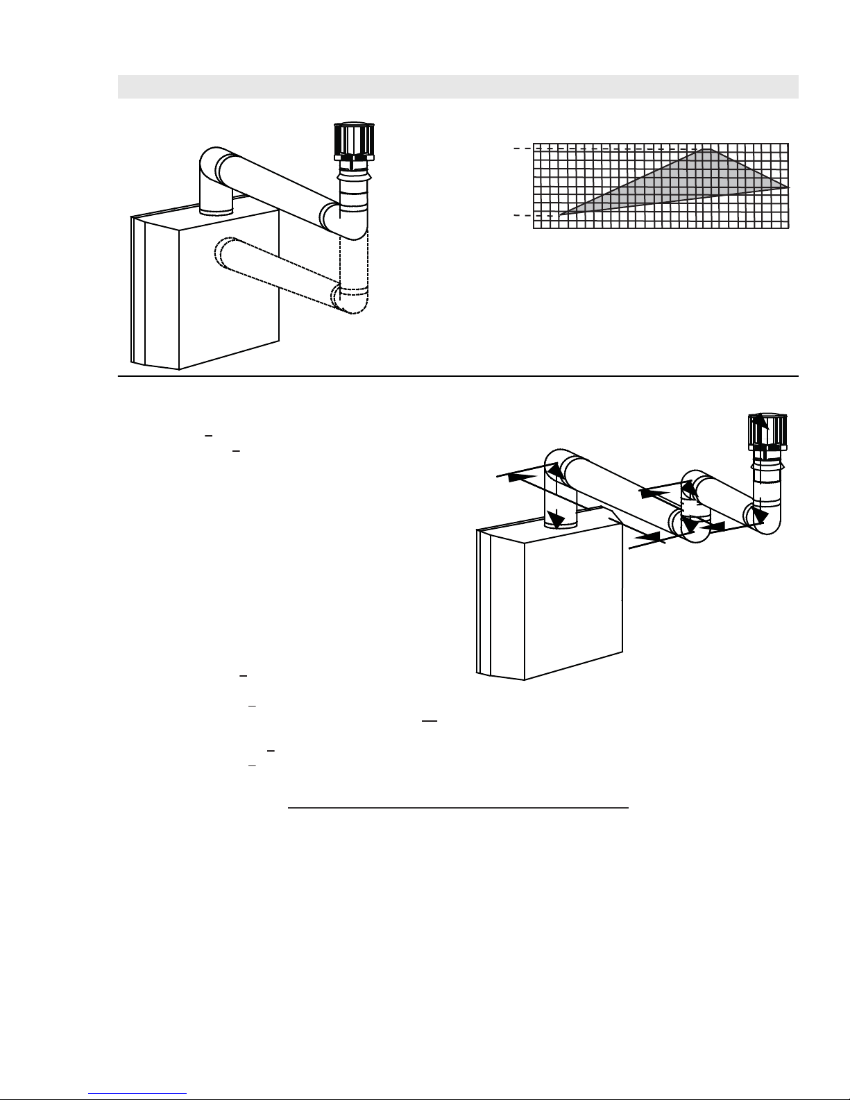
(HT) > (VT)
Simple venting configurations.
See graph to determine the required vertical rise V
required horizontal run H
20
19
.
T
for the
T
REQUIRED
VERTICAL
RISE IN
FEET V
10
T
3
0
5101520
25 30
HORIZONTAL VENT RUN PLUS OFFSET IN FEET H
The shaded area within the lines represents acceptable
values for H
and HT
T
For vent configurations requiring more than two 90° elbows (top exit) or one 90° elbow (rear exit), the following
formulas apply:
Formula 1: H
Formula 2: HT + V
< 3 V
T
T
< 40 feet
T
90°
90°
Example 7:
V
= 2 FT
1
V
= 1 FT
2
= 1.5 FT
V
3
V
= V
+ V2 + V3 = 2 + 1 + 1.5 = 4.5 FT
T
1
= 6 FT
H
1
H
= 2 FT
2
H
= H
+ H
R
= .03 (four 90° elbows - 90°)
H
O
= .03 (360° - 90°) = 8.1 FT
H
= H
T
H
+ V
T
= 6 + 2 = 8 FT
1
2
+ H
= 8 + 8.1 = 16.1 FT
R
O
= 16.1 + 4.5 = 20.6 FT
T
V
1
H
1
V
H
2
2
90°
V
3
90°
T
Formula 1: H
3.5 V
16.1 < 13.5
< 3.5 V
T
T
= 3 x 4.5 = 13.5 FT
T
Since this formula is not met, this vent configuration is unacceptable.
Formula 2: HT + V
16.1 < 13.5
< 40 FT
T
Since only formula 2 is met, this vent configuration is unacceptable and a new fireplace location or vent configuration will
need to be established to satisfy both formulas.
18.2_2A
W415-0899 / 06.01.10
20
Example 8:
= 1.5 FT
V
1
V
= 5 FT
2
= V
V
H
H
H
H
H
= .03 (360° + 45° - 90°) = 6.75 FT
H
H
Formula 1:
HT < 3 V
3 V
19.5 = 19.5
+ V2 = 1.5 + 1 + 5 = 6.5 FT
T
1
= 1 FT
1
= 1 FT
2
= 10.75 FT
3
= H
+ H2 + H3 = 1 + 1 + 10.75 = 12.75 FT
R
1
= .03 (four 90° elbows + one 45° elbow - 90°)
O
= H
+ H
T
+ V
T
= 12.75 + 6.75 = 19.5 FT
R
O
= 19.5 + 6.5 = 26 FT
T
T
= 3 x 6.5 = 19.5 FT
T
90°
V
H
1
Formula 2:
HT + V
26 < 40
< 40 FT
T
Since both formulas are met, this vent configuration is acceptable.
V
2
H
2
45°
1
H
3
90°
90°
18.2_3
4.0 PRE-INSTALLATION PREPARATION
For optimum performance, it is recommended that all horizontal runs have a 1" rise per foot.
4.1 REMOVING THE VALVE ACCESS DOOR AND TOP DOOR TRIM
4.1.1 The valve access door rotates on the pins
attached to the side frame. Lift the valve access
door off the pins to operate the main glass door.
4.1.2 Lift the top door trim off the top of the door.
T
O
P
DO
O
R TR
IM
W415-0899 / 06.01.10
4.2 DOOR OPERATION
To access the lower door latch, open the Valve Access Door as illustrated. Release
the top and bottom door latches, located at the right side of the door.
4.3 REAR EXIT
FAILURE TO INSTALL THE CAP WILL CAUSE THE APPLIANCE TO FUNCTION IMPROPERLY AND
From inside the fi rebox, insert the 4" fl ue pipe / gasket assembly (provided) through the
rear of the fi rebox. Secure the gasket assembly to the rear and top of the appliance using
4 #8 x ¾ inch Hex Head Wildrill screws supplied.
Do not overtighten. The gasket needs only to be snug against the fi rebox.
Before attaching elbows to the collars on the back of the appliance, 1½" will need to be
trimmed off the 4" collar.
!
WARNING
CAN CAUSE INJURY OR PROPERTY DAMAGE.
21
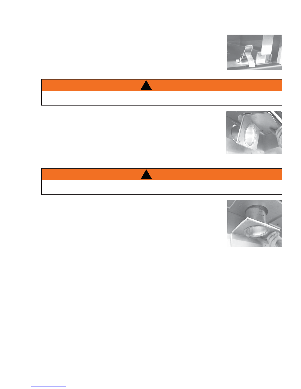
4.4 TOP VENT
FAILURE TO INSTALL THE CAP WILL CAUSE THE APPLIANCE TO FUNCTION IMPROPERLY AND
4.4.1 Remove the 7" diameter cap from the top of the appliance and re-secure
it over the 7" collar located at the rear of the appliance. Press fi rmly on the
cap while securing to ensure an airtight seal. Do not damage the gasket.
4.4.2 Remove the plate covering the 4" diameter fl ue opening (seen inside the
top of the 7" diameter collar) and discard. Try not to disturb the retaining
ring or the gasket beneath. Re-secure the ring and gasket using the screws
removed from the plate.
4.4.3 From inside the fi rebox, insert the 4" fl ue pipe / gasket assembly through the heat shield and out
through the retaining ring. Secure the assembly to the rear and top of the appliance using 4 #8 x ¾"
Hex Head Wildrill screws supplied. Do not overtighten. The gasket needs only to be snug against the
fi rebox.
!
WARNING
CAN CAUSE INJURY OR PROPERTY DAMAGE.
W415-0899 / 06.01.10
 Loading...