

Napoleon GD33NR, BGD33NR, BGD34NT, GD33PR, GD34PT Installation And Operating Instructions Manual
...
1
$10.00
W415-0341 / K / 10.05.07
2
y
t
e
t
,
d
t
e
d
g
n
TABLE of CONTENTS
PG 3-5 INTRODUCTION
Warranty
General Instructions
General Information
Care of Glass & Plated Parts
Dimensions
5-14 VENTING
Venting Lengths
Air Terminal Locations
Venting Application Flow Chart
Venting Specifications
15-24 INSTALLATION
Wall & Ceiling Protection
Using Flexible Vent Components
Using Rigid Vent Components
Restricting Vertical Vents
Mobile Home Installation
Gas Installation
Framing
Nailing Tab Installation
Mantle Clearances & Enclosures
PLEASE RETAIN THIS MANUAL FOR FUTURE REFERENCE
25-27 FINISHING
Log Placement
Door Removal & Installation
Logo Placement
Louvre Removal & Installation
28 OPTIONAL BLOWER
29-30 OPERATION / MAINTENANCE
Operating Instructions
Maintenance
30 ADJUSTMENTS
Pilot Burner Adjustment
Venturi Adjustment
31-33 REPLACEMENTS
Ordering Replacement Parts
Replacement Parts
Accessories
Vent Kits
Terminal Kits
34-35 TROUBLE SHOOTING GUIDE
36 NOTES
WARNING
• Do not burn wood or other materials in this fireplace.
• Adults and especially children should be alerted to the hazards of high surface temperatures and should stay awa
to avoid burns or clothing ignition. Supervise young children when they are in the same room as the fireplace.
• Clothing or other flammable material should not be placed on or near the fireplace.
• Due to high temperatures, the fireplace should be located out of traffic and away from furniture and draperies.
• Ensure you have incorporated adequate safety measure to protect infants/toddlers from touching hot surfaces.
• Even after the fireplace is out, the glass and/or screen will remain hot for an extended period of time.
• Check with your local hearth specialty dealer for safety screens and hearth guards to protect children from ho
surfaces. These screens and guards must be fastened to the floor.
• Any safety screen or guard removed for servicing must be replaced prior to operating the fireplace.
• It is imperative that the control compartments, burners and circulating blower and its passageway in the fireplac
and venting system are kept clean. The fireplace and its venting system should be inspected before use and at leas
annually by a qualified service person. More frequent cleaning may be required due to excessive lint from carpeting
bedding material, etc. The fireplace area must be kept clear and free from combustible materials, gasoline an
other flammable vapours and liquids.
• Under no circumstances should this fireplace be modified.
• This fireplace must not be connected to a chimney flue pipe serving a separate solid fuel burning appliance.
• Do not use this fireplace if any part has been under water. Immediately call a qualified service technician to inspec
the fireplace and to replace any part of the control system and any gas control which has been under water.
• Do not operate the fireplace with the glass door removed, cracked or broken. Replacement of the glass should b
done by a licensed or qualified service person.
• Do not strike or slam shut the fireplace glass door.
• This fireplace uses and requires a fast acting thermocouple. Replace only with a fast acting thermocouple supplie
by Wolf Steel Ltd.
• Pressure relief doors must be kept closed while the fireplace is operating to prevent exhaust fumes containin
carbon monoxide, from entering into the home. Temperatures of the exhaust escaping through these openings ca
also cause the surrounding combustible materials to overheat and catch fire.
• Only doors / optional fronts certified with the unit are to be installed on the appliance.
NOTE: Changes, other than editorial, are denoted by a vertical line in the margin.
W415-0341 / K / 10.05.07
3
®
®
®
®
®
®
®
®
®
®
®
®
®
®
®
®®
®
®
®
®
W415-0341 / K / 10.05.07
4
GENERAL INSTRUCTIONS
THIS GAS FIREPLACE SHOULD BE INSTALLED AND
SERVICED BY A QUALIFIED INSTALLER to conform with
local codes. Installation practices vary from region to region and it is important to know the specifics that apply to
your area,
for example: in Massachusetts State:
• The fireplace damper must be removed or welded in the open
position prior to installation of a fireplace insert or gas log.
• A carbon monoxide detector is required in all rooms containing
gas fired appliances.
• The appliance off valve must be a “T” handle gas cock.
• The flexible connector must not be longer than 36 inches.
• The appliance is not approved for installation in a bedroom or
bathroom unless the unit is a direct vent sealed combustion
product.
• WARNING: This product must be installed by a licensed plumber
or gas fitter when installed within the commonwealth of
Massachusetts.
In absence of local codes, install to the current National
Fuel Gas Code, ANSI Z223.1, or the current CAN/CGA B149,
Installation Codes. Mobile home installation must conform
with local codes or in the absence of local codes, install to
the current standard for gas equipped mobile housing CAN/
CSA ZA240 MH Series in Canada or the Manufactured
Home Construction and Safety Standard, Title 24 CFR, Part
3280, or the Fire Safety Criteria for Manufactured Home
Installations, Sites, and Communities Standard ANSI/NFPA
501A in the United States.
The fireplace and its individual shutoff valve must be disconnected from the gas supply piping system during any
pressure testing of that system at test pressures in excess
of 1/2 psig (3.5 kPa). The fireplace must be isolated from
the gas supply piping system by closing its individual
manual shutoff valve during any pressure testing of the
gas supply piping system at test pressures equal to or
less than 1/2 psig (3.5 kPa).
When the fireplace is installed directly on carpeting, vinyl
tile or other combustible material other than wood flooring,
the fireplace shall be installed on a metal or wood panel
extending the full width and depth.
If the optional blower is installed, the receptacle / junction
box must be electrically connected and grounded in accordance with local codes. In the absence of local codes,
use the current CSA C22.1 CANADIAN ELECTRICAL CODE
in Canada or the ANSI/NFPA 70 NATIONAL ELECTRICAL
CODE in the United States.
GENERAL INFORMATION
Models GD33 and BGD33 have been certified by Intertek
Testing Services under the Warnock Hersey Logo.
Models GD34 and BGD34 have been certified by Underwriters' Laboratorities of Canada under the UL Logo.
FOR YOUR SA TISF ACTION, THIS FIREPLACE HAS BEEN
TEST-FIRED TO ASSURE ITS OPERATION AND QUALITY!
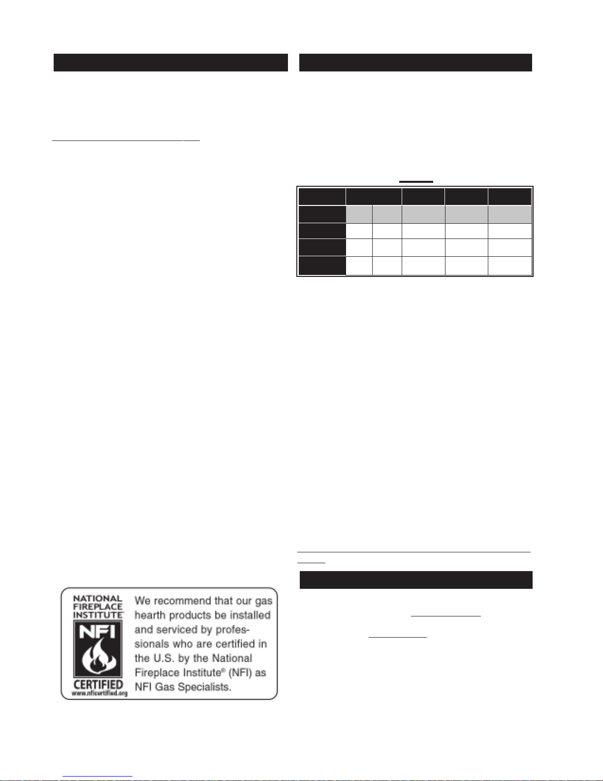
MODEL RA TES AND EFFICIENCIES
MODEL *GD33 BGD33 GD34 BGD34
ALTITUDE
MAX. INPUT
BTU/HR
MAX. OUTPUT
BTU/HR
EFFICIENCY
W/ THE FAN ON
0-2000 2000-4500 0-4500 0-4500 0-4500
FT
22,000 20,000 16,400 24,500 19,000
17,380 15,800 11,644 20,090 14,820
79% 79% 71% 82% 78%
*For elevations between 2,000 and 4,500 ft. above sea
level, this fire place must be de-rated by 10% using the
certified High Altitude Kit.
This fireplace is approved for bathroom, bedroom and
bed-sitting room installations and is suitable for mobile
home installation.
No external electricity (1 10 volts or 24 volts) is required
for the gas system operation.
Expansion / contraction noises during heating up and
cooling down cycles are normal and are to be expected.
Provide adequate circulation air. Provide adequate accessibility clearance for servicing and operating the fireplace. Never obstruct the front opening of the fireplace.
Purge all gas lines with the glass door of the fireplace
removed. Assure that a continuous gas flow is at the
burner before installing the door.
Under extreme vent configurations, allow several
minutes (5-15) for the flame to stablize after ignition.
Six inches is the minimum bend radius allowed for the 7"
diameter flexible liner.
Objects placed in front of the fireplace must be kept at a
minimum of 48" from the front face of the unit.
Use only accessories designed for and listed with the
model.
T ABLE 1
W415-0341 / K / 10.05.07
CARE OF GLASS, AND PLATED PARTS
Do not use abrasive cleaners to clean plated parts. Buff
lightly with a clean dry cloth. BGD33 / BGD34: The glass is
3
/16" tempered glass available from your Napoleon® / Wolf
Steel Ltd. dealer. GD33 / GD34: The glass is 3/16" ceramic
glass available from your Napoleon® / Wolf Steel Lt d. dealer.
DO NOT SUBSTITUTE MATERIALS. Clean the glass after
the first 10 hours of operation with a recommended gas
fireplace glass cleaner. Thereafter clean as required. DO
NOT CLEAN GLASS WHEN HOT! If the glass is not kept
clean permanent discolouration and / or blemishes may
result.
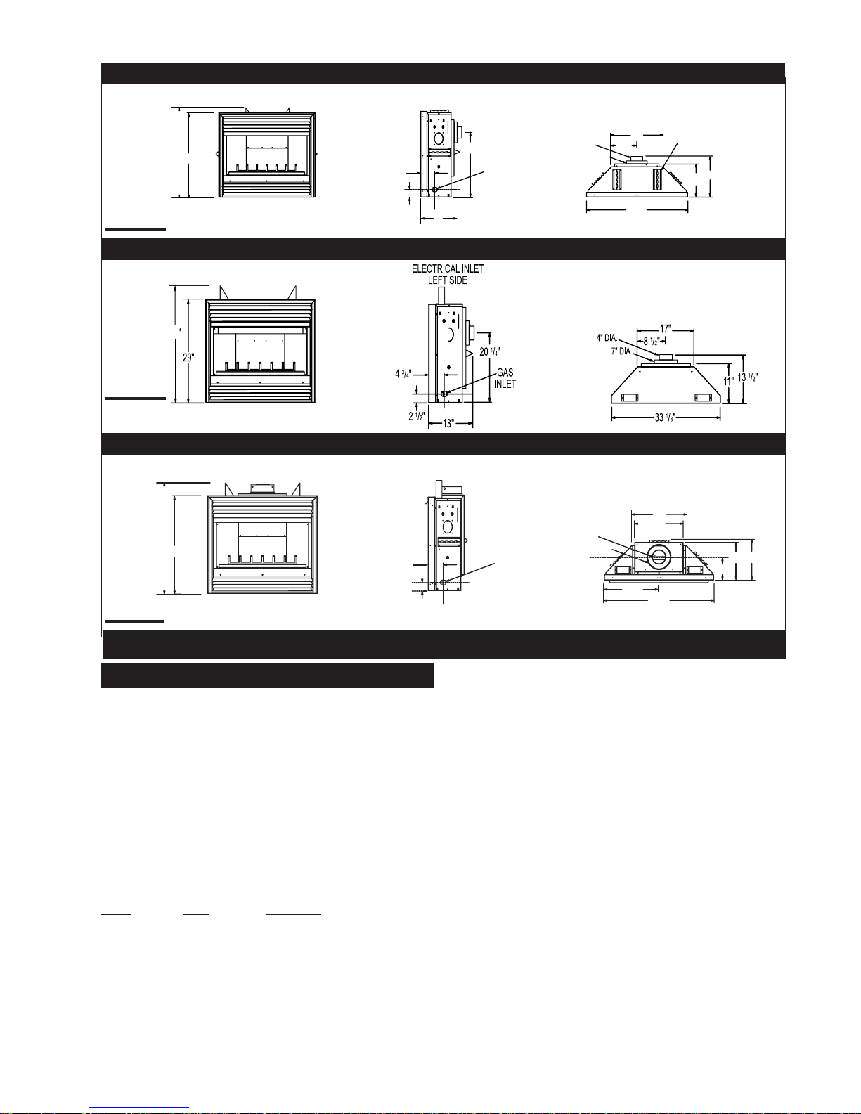
GD33NR
ELECTRICAL INLET
LEFT SIDE
5
FIGURE 1a
FIGURE 1b
33 1/8"
FIGURE 1c
33
29
35"
17"
1
/4"
6” STAND OFF
1
/2"
13
11"
29
7" DIA.
1
/2"
8
34
4" DIA.
13"
20 1/4"
GAS
INLET
5
/8"
3
5
/4"
2 5/8"
BGD33NR
B/GD34NT
ELECTRICAL INLET
LEFT SIDE
17"
17
15"
11"
13"
6 3/4"
1
/8"
1
34
/4"
5
/8"
3
/4"
5
2 5/8"
GAS
INLET
4" DIA.
7" DIA.
VENTING LENGTHS AND AIR TERMINAL LOCATIONS
Use only Wolf Steel, Simpson Dura-Vent, Selkirk Direct
Temp or American Metal Amerivent venting components.
Minimum and maximum vent lengths, for both horizontal
and vertical installations, and air terminal locations for
either system are set out in this manual and must be
adhered to. For Simpson Dura-Vent, Selkirk Direct Temp
and American Metal Amerivent, follow the installation
procedure provided with the venting components.
All outer pipe joints of these venting systems must be
sealed using Red RTV High Temperature Sealant.
A starter adaptor must be used with the following vent
systems and may be purchased from the corresponding
supplier:
PART 4"/7" SUPPLIER
Duravent W175-0053 Wolf Steel
Amerivent 4DSC-N2 American Metal
Direct T emp 4DT-AAN Selkirk
For vent systems that provide seals on the inner exhaust
flue, only the outer air intake joints must be sealed using
a red high temperature silicone (RTV). This same
sealant may be used on both the inner exhaust and the
outer intake vent pipe joints of all other approved vent
systems except for the exhaust vent pipe connection to
the fireplace flue collar which must be sealed using the
black high temperature sealant Mill Pac.
VENTING
When using Wolf Steel venting components, use only
approved Wolf Steel rigid / flexible components with the
following termination kits:Wall Terminal Kit GD222, or 1/12
to 7/12 Pitch Roof Terminal Kit GD110, 8/12 to 12/12 Roof
Terminal Kit GD111, Flat Roof Terminal Kit GD112 or
Periscope Kit GD201 (for wall penetration below grade).
With flexible venting, in conjunction with the various
terminations, use either the 5 foot Vent Kit GD220 or the 10
foot Vent Kit GD330.
The maximum allowable vertical vent length is 40 feet.
For optimum flame appearance and fireplace performance,
keep the vent length and number of elbows to a minimum.
The air terminal must remain unobstructed at all times.
Examine the air terminal at least once a year to verify that it
is unobstructed and undamaged.
Horizontal runs may have a 0 inch rise per foot in all
cases using Wolf Steel, Simpson Dura-Vent, Selkirk
Direct Temp, or American Metal Amerivent rigid vent
components and Wolf Steel flexible vent components.
For optimum performance, it is recommended that
horizontal runs have a minimum 1/4 inch rise per foot
when using Simpson Dura-Vent, Selkirk Direct Temp,
American Metal Amerivent or Wolf Steel rigid vent
components and a minimum 1 inch rise per foot when
using Wolf Steel flexible vent comonents. For safe and
proper operation of the fireplace,
follow the venting instructions exactly.
W415-0341 / K / 10.05.07
6
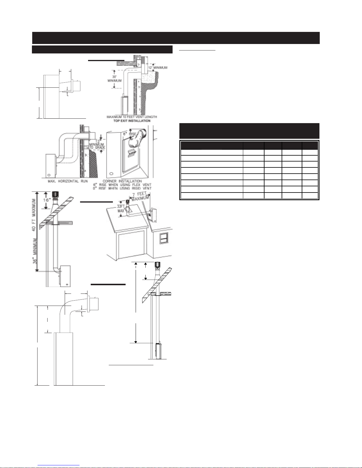
TYPICAL VENT INSTALLATIONS
24" MAXIMUM
8" MINIMUM (BGD33)
12" MINIMUM (GD33)
1" RISE / FT *
20 1/4"
* REFER TO "VENTING SECTION"
VENT INSTALLATIONS
FIGURES 2a - d
ALL MODELS: Vent lengths that pass through unheated
spaces (attics, garages, crawl spaces) should be insulated with the insulation wrapped in a protective sleeve
to minimize condensation.
Provide a means for visually checking the vent connection to the fireplace after the fireplace is installed.
Do not allow the inside liner to bunch up on horizontal or
vertical runs and elbows. Keep it pulled tight. A 1¼" air
gap between the inner and outer liner all around is required for safe operation.
Use a firestop, vent pipe shield or attic insulation shield
when penetrating interior walls, floor or ceiling.
Minimum clearance to combustible construction
from fireplace and vent surfaces:
FIGURE 3a - b
16”
MINIMUM
F I G U R E 4 a - b
24” MAX
11” MIN
10” MINIMUM
24” MINIMUM
53 5/8”
(BGD34)
(GD34)
1” RISE/FT*
40 FT MAXIMUM
3 FT MINIMUM
BGD33 and GD33: When
venting straight out the
back, only the rigid vent
can be used. Do not use
* REFER TO “VENTING SECTION”
flexible vent. For all other
venting configurations, flexible vent is acceptable. When
venting either a GD33 or a BGD33, the horizontal run
must be kept to a maximum of 24 inches. A GD33 must
be kept to a minimum of 12 inches and a BGD33 must be
kept to a minimum of 8 inches. When terminating vertically, the vertical rise is a minimum 36 inches to a maximum 40 feet from the centre of the fireplace flue outlet.
W415-0341 / K / 10.05.07
TABLE 2
SIDE OF THE UNIT 0" 0" 0" 0"
BACK OF THE UNIT 0" 0" 0" 0"
BOTTOM OF THE UNIT 0" 0" 0" 0"
TOP OF THE UNIT 0" 0" 0" 51/8"**
TOP OF THE VENT PIPE 2"* 2"* 2" 2"
SIDES OF THE VENT PIPE 1" 1" 1" 1"
BOTTOM OF THE VENT PIPE 1" 1" 1" 1"
RECESSED DEPTH 13" 13" 13" 13"
BGD33 GD33 BGD34 GD34
* A clearance to combustibles of 2" at the vent pipe top
must be maintained. The firestop spacer W010-1777sup-
plied with the unit must be used to maintain this clearance.
** The first 5 1/8" of finishing material above the GD34
must be non-combustible. The header must be steel.
For safe and proper operation of the fireplace follow the
venting instruction exactly.
Deviation from the minimum or the maximum vertical
vent length can create difficulty in burner start-up and/
or carboning.
A terminal shall not terminate directly above a sidewalk
or paved driveway which is located betweeen two single family dwellings and serves both dwellings. Local
codes or regulations may require different clearances.
In order to avoid the possibility of exposed insulation or
vapour barrier coming in contact with the fireplace
body, it is recommended that the walls of the fireplace
enclosure be “finished” (ie: drywall/sheetrock), as you
would finish any other outside wall of a home. This will
ensure that clearance to combustibles is maintained
within the cavity.
Wolf Steel, Simpson Dura-Vent, Selkirk Direct Temp and
American Metal Amerivent venting systems must not be
combined.
Purge all gas lines with the glass door of the fireplace
open. Assure that a continuous gas flow is at the burner
before closing the door.
Under extreme vent configurations, allow several minutes
(5-15) for the flame to stabilize after ignition.
Six (6") inches is the minimum bend radius allowed for
the 7" diameter flexible liner.
FOR SPECIFIC VENTING PARAMETERS, REFER T O
PAGES 9-14.
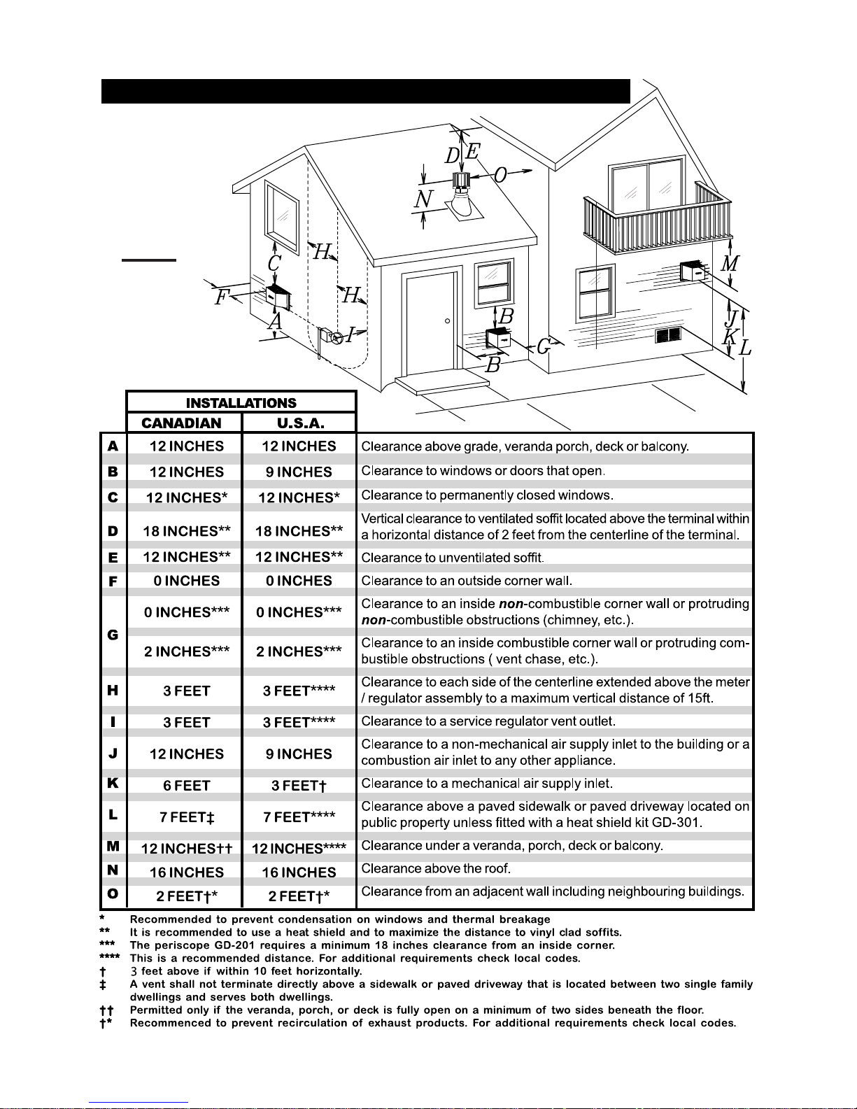
MINIMUM AIR TERMINAL LOCATION CLEARANCES
FIGURE 5
7
W415-0341 / K / 10.05.07
8
l
l
tiontion
tiontion
tion
minamina
minamina
mina
erer
erer
er
TT
TT
T
tical tical
tical tical
tical
erer
erer
er
VV
VV
V
than
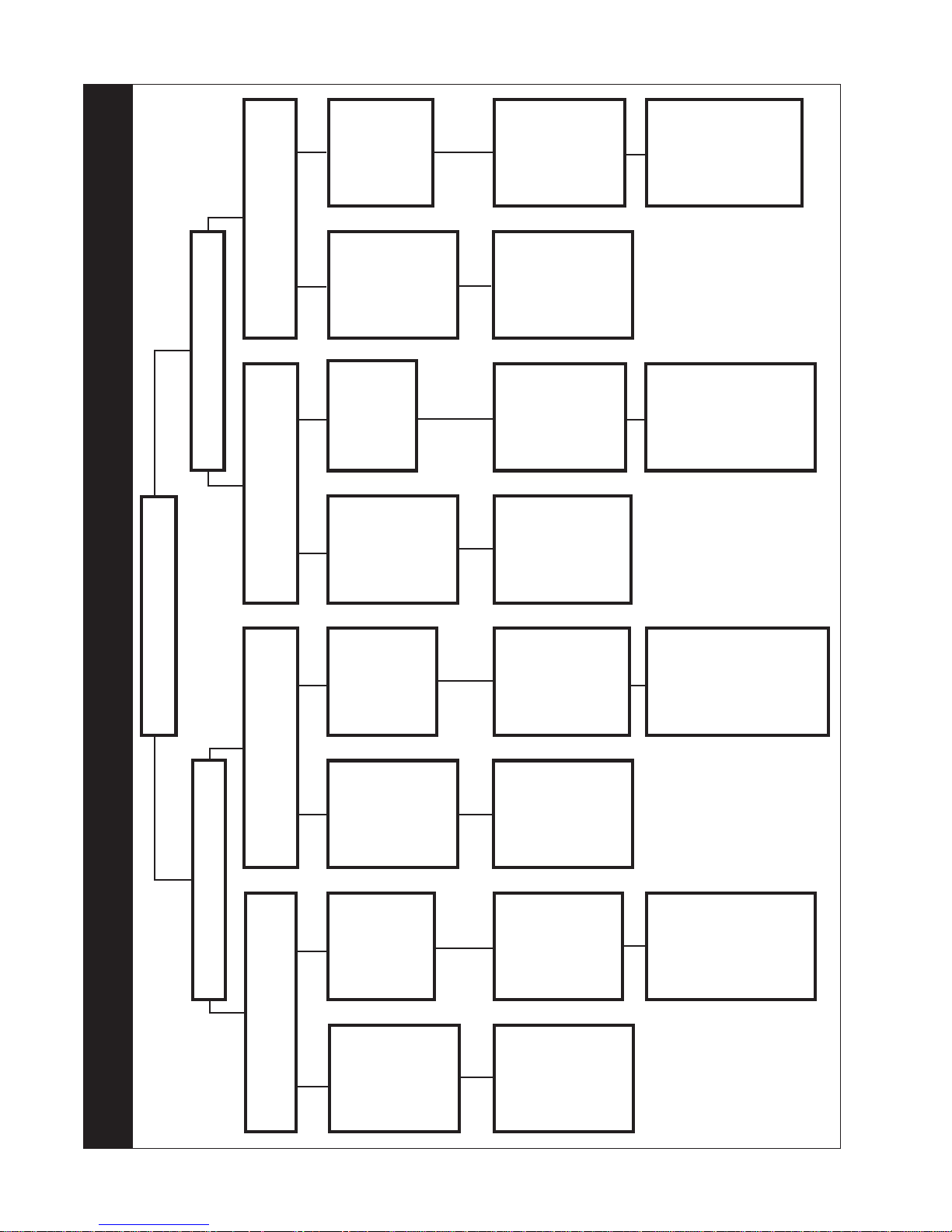
Vertical
rise is less
or greater
is equal to
Vertical rise
run
horizontal
run
than the
horizontal
run +
rise to
vertical
Horizontal
run +
rise to
vertical
Horizontal
of 40 feet
maximum
of 40 feet
maximum
3 times the
greater
equal to or
vertical rise
run
than the
horizontal
BGD34 & GD34BGD34 & GD34
BGD34 & GD34BGD34 & GD34
BGD34 & GD34
ent Exitent Exit
ent Exitent Exit
ent Exit
VV
VV
V
place place
place place
place
ee
ee
e
FirFir
FirFir
Fir
tiontion
tiontion
tion
minamina
minamina
mina
erer
erer
er
HorizontalHorizontal
HorizontalHorizontal
Horizontal
TT
TT
T
tiontion
tiontion
tion
minamina
minamina
mina
erer
erer
er
TT
TT
T
tical tical
tical tical
tical
erer
erer
er
VV
VV
V
Vertical rise
Vertical rise
Vertical
Vertical rise
run
horizontal
is less than
than the
or greater
is equal to
rise is less
is equal to
horizontal
run
than
horizontal
than the
or greater
horizontal
run
run
run +
Horizontal
Horizontal
Horizontal
Horizontal
to maxi-
vertical rise
run +
vertical
run +
vertical
run +
rise to
vertical
mum of
24.75 feet
rise to
of 40 feet
maximum
rise to
of 40 feet
maximum
of 40 feet
maximum
4.2 times
rise equal
the vertica
equal to or
3 times the
vertical rise
to or
greater
greater
run
than the
horizontal
run
than the
horizontal
VENTING APPLICATION FLOW CHART
BGD33 & GD33BGD33 & GD33
BGD33 & GD33BGD33 & GD33
BGD33 & GD33
tiontion
tiontion
tion
minamina
minamina
mina
erer
erer
er
HorizontalHorizontal
HorizontalHorizontal
Horizontal
TT
TT
T
W415-0341 / K / 10.05.07
than
Vertical
rise is less
or greater
is equal to
Vertical rise
run
horizontal
run
than the
horizontal
run +
Horizontal
Horizontal
to maxi-
vertical rise
run +
rise to
vertical
mum of
24.75 feet
of 40 feet
maximum
3.5 times
rise equal
the vertica
to or
greater
run
than the
horizontal
9
DEFINITIONS
for the following symbols used in the venting calculations and examples are:
> - greater than
> - equal to or greater than
< - less than
< - equal to or less than
H
- total of both horizontal vent lengths (HR) and offsets
T
(HO) in feet
H
- combined horizontal vent lengths in feet
R
H
- offset factor: .03(total degrees of offset - 90°
O
feet
V
- combined vertical vent lengths in feet
T
**
*) in
**
ELBOW VENT LENGTH VALUES
feet inches
1° 0.03 0.5
15° 0.45 6.0
30° 0.9 11.0
45° 1.35 16.0
**
90°
* 2.7 32.0
**
* *
* the first 90° offset has a zero value and is shown in
* *
the formula as -90°
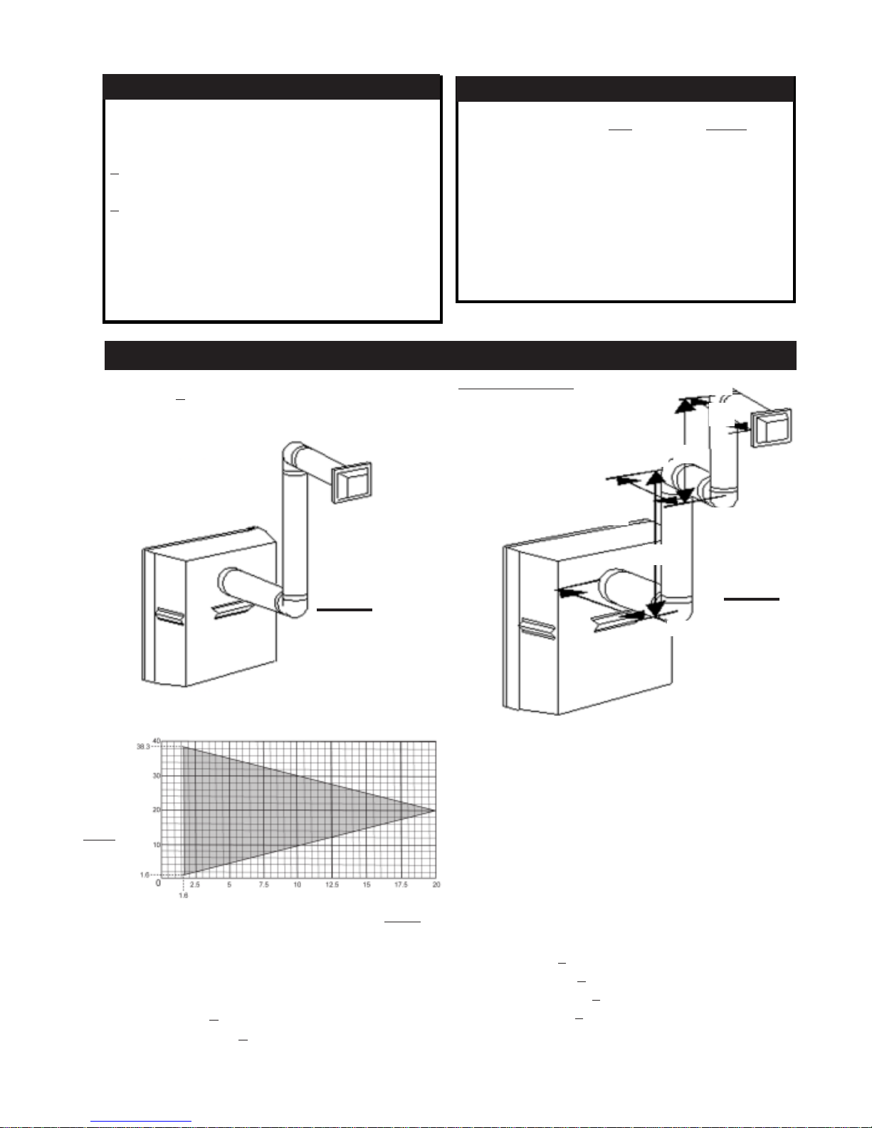
BGD33 & GD33 HORIZONTAL TERMINATION
Example 1:Example 1:
Example 1:
(H(H
) )
<<
(V (V
when
(H
(H(H
)
) )
TT
T
TT
<
<<
(V
(V (V
))
)
))
TT
T
TT
Simple venting configuration (only two 90° elbows)
Example 1:Example 1:
H
2
90°
V
90°
2
H
3
90°
FIGURE 6
See graph to determine the required vertical rise VT for the
required horizontal run H
T
REQUIRED
VERTICAL
RISE IN
FEET
V
T
HORIZONTAL VENT RUN PLUS OFFSETS IN FEET
The shaded area within the lines represents acceptable
values for HT and V
.
T
For vent configurations requiring more than two 90° elbows the following formulas apply:
Formula 1: HT < V
T
Formula 2: HT + VT < 40 feet
V
1
H
1
V
1
V
2
V
T
H
1
H
2
H
3
H
R
H
O
=9 f t
=6 f t
=
V1 +
V2 =
9 + 6 = 15 ft
=3 f t
=2 f t
=1.5 ft
=H1 + H2 + H3 = 3 + 2 + 1.5 = 6.5 ft
=.03(four 90° elbows - 90°)
=.03(90 + 90 + 90 + 90 - 90) = 8.1 ft
H
HH
H
HH
T
TT
T
TT
HT + VT=14.6 + 15 = 29.6 ft
Formula 1: HT < V
=HR + HO = 6.5 + 8.1 = 14.6 ft
T
14.6 < 15
Formula 2: HT + VT < 40 feet
29.6 < 40
Since both formulas are met, this vent configuration is acceptable.
FIGURE 7
90°
W415-0341 / K / 10.05.07
10
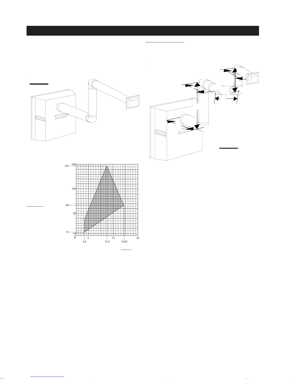
BGD33 & GD33 HORIZONTAL TERMINATION
(H(H
(H
(H(H
) > (V) > (V
) > (V
) > (V) > (V
TT
T
TT
when
Simple venting configuration (only two 90° elbows)
FIGURE 8
See graph to determine the required vertical rise VT for the
required horizontal run H
))
)
))
TT
T
TT
T
Example 2:Example 2:
Example 2:
Example 2:Example 2:
H
90°
H
90°
90°
45°
H
FIGURE 9
3
H
2
V
1
1
V
4
2
90°
REQUIRED
VERTICAL
RISE IN
INCHES
V
T
HORIZONTAL VENT RUN PLUS OFFSETS IN
FEET
HH
H
HH
The shaded area within the lines represents acceptable
values for HT and V
.
T
For vent configurations requiring more than two 90° elbows
the following formulas apply:
Formula 1: HT < 3.5V
T
Formula 2: HT + VT < 24.75 feet
V
1
V
2
V
T
H
1
H
2
H
3
H
4
H
R
H
O
=4 f t
=1.5 ft
=
V1 +
V2 =
4 + 1.5 = 5.5 ft
=2 f t
=1 f t
=1 f t
=1.5 ft
=H1 + H2 + H3 + H4 = 2 + 1 + 1 + 1.5 = 5.5 ft
=.03(four 90° elbows + one 45° elbow - 90°)
=.03(90 + 90 + 90 + 90 + 45 - 90) = 9.45 ft
H
T
=HR + HO = 5.5 + 9.45 = 14.95 ft
HT + VT= 14.95 + 5.5 = 20.45 ft
Formula 1: HT < 3.5V
TT
T
TT
14.95 < 19.25
T
3.5VT =
3.5 x
5.5 = 19.25 ft
Formula 2: HT + VT < 24.75 feet
20.45 < 24.75
Since both formulas are met, this vent configuration is acceptable.
W415-0341 / K / 10.05.07
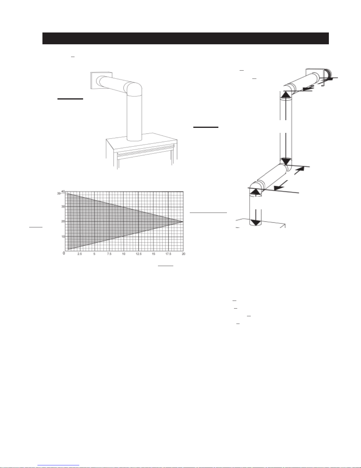
BGD34 & GD34 HORIZONTAL TERMINATION
11
when (H
) < (VT)
T
Simple venting configuration (only one 90° elbow)
FIGURE 10
See graph to determine the required vertical rise VT for the
required horizontal run HT.
VERTICAL
RISE IN
FEET
V
T
HORIZONTAL VENT RUN PLUS OFFSET IN FEET
The shaded area within the lines represents acceptable
values for HT and V
.
T
For vent configurations requiring more than one 90° elbow, the following formulas apply:
Formula 1: HT < V
T
Formula 2: HT + VT < 40 feet
90°
FIGURE 11
90°
V
Example 3:
V
=3 ft
1
V
=8 ft
2
V
=
V
+
V
=
3 + 8 = 1 1 ft
2
< V
T
T
9.9 < 1 1
+ VT < 40 feet
T
20.9 < 40
H
HH
HH
TT
T
TT
T
H
1
H
2
H
R
H
O
H
T
HT + V
1
= 2.5 ft
=2 ft
= H1 + H2 = 2.5 + 2 = 4.5 ft
=.
03(three 90° elbows - 90°) = .03(270° - 90°) = 5.4 ft
= HR + HO = 4.5 + 5.4 = 9.9 ft
= 9.9 + 11 = 20.9 f t
T
Formula 1: H
Formula 2: H
Since both formulas are met, this vent configuration is acceptable.
1
V
2
H
90°
1
H
2
W415-0341 / K / 10.05.07
 Loading...