

Page 1
INSTALLER: LEAVE THESE INSTRUCTIONS WITH THE APPLIANCE THIS TERMINAL IS SERVING.
CONSUMER: RETAIN THESE INSTRUCTIONS FOR FUTURE REFERENCE.
THESE INSTRUCTIONS ARE TO BE USED IN CONJUNCTION WITH THE APPLIANCE AND PVA INSTRUCTIONS.
INSTALLATION
INSTRUCTIONS
1
CERTIFIED UNDER CANADIAN AND AMERICAN NATIONAL STANDARDS: ANSI Z21.88 CSA 2.33 FOR VENTED GAS FIREPLACE HEATERS
AND ANSI Z21. CSA 2.22 FOR VENTED GAS FIREPLACES.
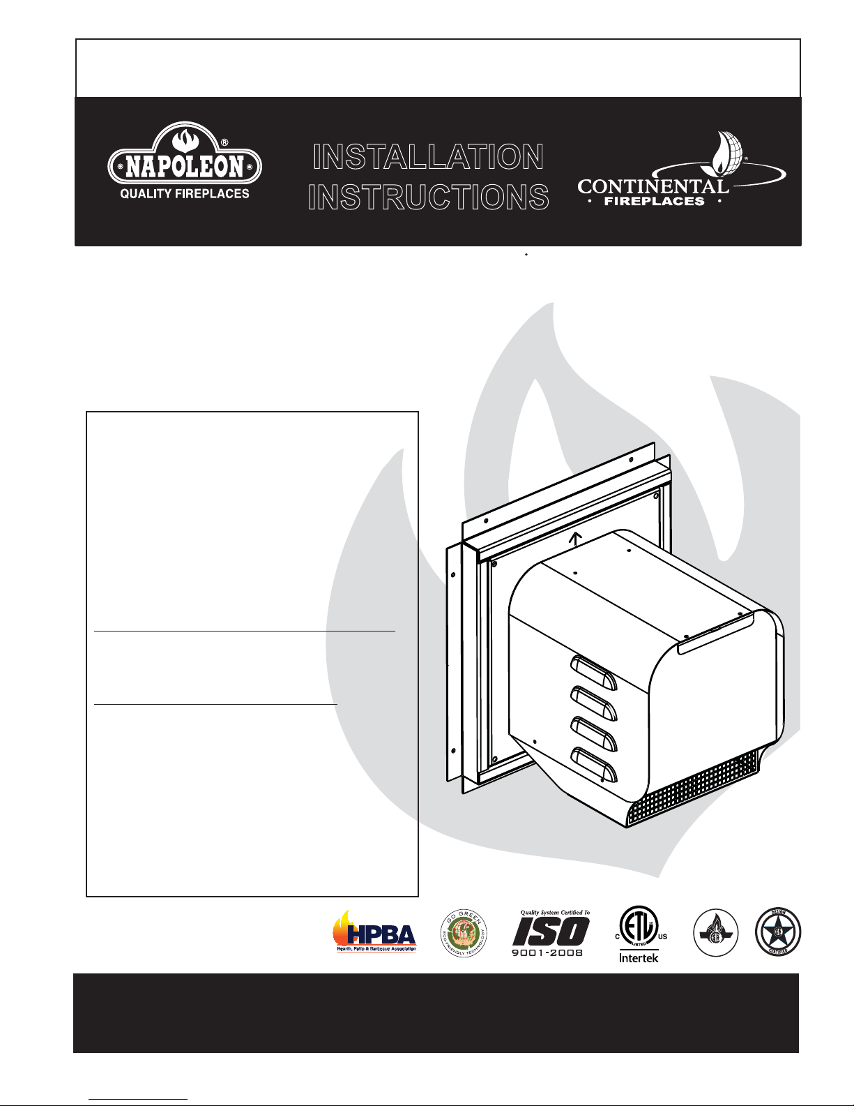
GAS POWER VENT
The GPV is a Direct Vent Terminal
(GPV)
GENERAL INFORMATION
These Installation Instructions must be used in conjunction
with the appliance and appropriate PVA adapter kit Installation
Instructions. Clearances listed in these Instructions supersede
those in the appliance's Installation Instructions.
Power venting of direct vent appliances may result in the
reduction of efficiencies by as much as ten percent. Consider
this in making any venting and heating decisions in any
installation application.
SELECTING AND INSTALLING THE APPLIANCE
When selecting a gas appliance for use with the GPV, take into
consideration the various requirements and limitations in the
venting installation section for the following models:
Models Equipped with an Intermittent Pilot Ignition (I.P.I.)
It is recommended that the GPV be used with a gas appliance
equipped with an Intermittent Pilot Ignition (I.P.I.). Downward
vertical vent runs are permitted with an I.P.I. system. See
venting section in appropriate PVA Installation Instructions.
Models Equipped with Millivolt/ Standing Pilot
Downward vertical vent runs are not permitted with a standing
pilot system. See venting section in appropriate PVA Installation
Instructions.
INSTALLATION TO BE DONE BY A QUALIFIED INSTALLER
to conform with local codes. In absence of local codes install
to the current National Building Code in Canada or to regional
building codes in the United States. It must be electrically
connected and grounded in accordance with local codes. In
the absence of local codes, use the current CSA C22.1
CANADIAN ELECTRICAL CODE in Canada or the ANSI/NFPA
70 NATIONAL ELECTRIC CODE in the United States.
The GPV operates on 120 VAC 60 HZ electrical service which is
supplied at the firebox junction box.
designed to allow installation of
gas appliances where typical vent
configurations cannot be achieved.
Wolf Steel Ltd., 24 Napoleon Rd., Barrie, ON, L4M 4Y8 Canada /
103 Miller Drive, Crittenden, Kentucky, USA, 41030
0211212 fa[022031 ZZZ.napoleonfireplaceV.coP aVk#napoleon.on.ca
ZZZ.continentalfireplaceV.coP aVk#continentalfire.on.ca
$10.00
CERTIFIED
W415-0682 / D / 02.06.12
Page 2

2
TABLE OF CONTENTS
1.0 VENTING 2
1.1 INSTALLATION OVERVIEW 3
1.2 VENT TERMINAL CLEARANCES 4
1.3 VENT LENGTHS 5
1.4 POWER VENT TERMINAL 5
1.4.1 TERMINAL INSTALLATION 5
1.4.2 POWER VENT INSTALLATION 6
1.4.3 INITIAL FIRING PROCEDURES 6
1.4.4 ELECTRICAL CONNECTION 7
1.4.5 HARD WIRING CONNECTION 7
1.4.6 RECEPTACLE WIRING DIAGRAM 7
1.4.7 ELECTRICAL BOX INSTALLATION 8
1.5 RESTRICTOR PLATE INSTALLATION 9
1.6 WIRING DIAGRAM AND INSTALLATION 9
1.6.1 SIT IPI 885 PROFLAME COMPLETE WITH GPV POWER VENT TERMINAL 9
1.6.2 SIT MILLIVOLT 820 NOVA COMPLETE WITH GPV POWER VENT TERMINAL 11
1.6.3 SIT IPI 880/886 PROFLAME COMPLETE WITH GPV POWER VENT TERMINAL 12
1.6.4 DEXEN IPI 6003-3V COMPLETE WITH GPV POWER VENT TERMINAL 13
1.6.5 SIT REMOTE CONTROLLED MILLIVOLT SYSTEM COMPLETE WITH GPV POWER VENT TERMINAL 14
2.0 ADJUSTMENTS 15
2.1 VENTURI ADJUSTMENTS 15
3.0 REPLACEMENTS 15
4.0 TROUBLESHOOTING 16
NOTE: Changes, other than editorial, are denoted by a vertical line in the margin.
1.0 VENTING
There are specifi c adaptors and venting requirements for each appliance, refer to your power vent adaptor
leafl et for more information.
For complete installation instructions refer to the following web sites:
Manufacturer Website
Napoleon - English http://www.napoleonfi replaces.com/Tech/installation_manuals/installations.html
Napoleon - French http://www.napoleonfoyers.com/Fireplaces/powervent.html
Continental http://www.continentalfi replaces.com/fi replaces/gas/powervent.html
W415-0682 / D / 02.06.12
Page 3

1.1 INSTALLATION OVERVIEW
Reducer, refer to
power vent
adapter kit (PVA)
A typical vent
configuration
for specific venting instructions
where applicable.
LHD50 Illustrated
3
Electrical Box
(velcro to base)
Firestop
Spacer
Gas Power
Vent Terminal
Frame Assembly
Terminal
Access
Cover
W415-0682 / D / 02.06.12
Page 4

4
1.2 VENT TERMINAL CLEARANCES
COVERED BALCONY APPLICATIONS ††*
Q
S
R
G
P
Q
R
INSTALLATIONS
CANADA U.S.A.
A 12” 12” Clearance above grade, veranda porch, deck or balcony.
B 12”
C 12” * 12” * Clearance to permanently closed windows.
D 18” ** 18” **
E 12” ** 12” ** Clearance to unventilated soffi t.
F 0” 0” Clearance to an outside corner wall.
G
H 3’ 3’ ***
I 3’ 3’ *** Clearance to a service regulator vent outlet.
J 12” 9” Clearance to a non-mechanical air supply inlet to the building or a combustion air inlet to any other appliance.
K 6’ 3’ Clearance to a mechanical air supply inlet.
L 7’ ‡ 7’ *** Clearance above a paved sidewalk or paved driveway located on public property.
M 12” †† 12” *** Clearance under a veranda, porch or deck.
N 12” 12” Clearance above the roof.
O 2’ †* 2’ †* Clearance from an adjacent wall including neighbouring buildings.
P 8’ 8’ Roof must be non-combustible without openings.
Q 3’ 3’ See chart for wider wall dimensions.
R 6’ 6’
S 12” 12” Clearance under a covered balcony
Δ
* Recommended to prevent condensation on windows and thermal breakage
** It is recommended to maximize the distance to vinyl clad soffi ts.
*** This is a recommended distance. For additional requirements check local codes.
‡ A vent shall not terminate where it may cause hazardous frost or ice accumulations on adjacent property surfaces..
†† Permitted only if the veranda, porch, or deck is fully open on a minimum of two sides beneath the fl oor.
†* Recommended to prevent recirculation of exhaust products. For additional requirements check local codes.
††* Permitted only if the balcony is fully open on a minimum of one side.
Δ
0” 0” Clearance to an inside non-combustible corner wall or protruding non-combustible obstructions (chimney, etc.).
2” 2” Clearance to an inside combustible corner wall or protruding combustible obstructions (vent chase, etc.).
The terminal shall not be located less than 6 feet under a window that opens on a horizontal plane in a structure with three walls and a roof.
9”
Δ
Clearance to windows or doors that open.
Vertical clearance to ventilated soffi ts located above the terminal within a horizontal distance of 2’ from
the center line of the terminal.
Clearance to each side of the center line extended above the meter / regulator assembly to a maximum
vertical distance of 15’.
See chart for deeper wall dimensions. The terminal shall not be installed on any wall that has an opening between the terminal and the open side of the structure.
R
MIN
MAX
MAX
= 3 feet
= 2 x
Q
feet
12.2C
ACTUAL
W415-0682 / D / 02.06.12
Page 5
1.3 VENT LENGTHS
DETERMINE
THE
CORRECT
HEIGHT
REFER TO POWER VENT ADAPTER KIT (PVA) FOR SPECIFIC VENTING INSTRUCTIONS.
NOTE: If equipped, ACS switch must be disabled if there is any downward venting. Downward venting is not
allowed with appliances that use standing pilots.
1.4 POWER VENT TERMINAL
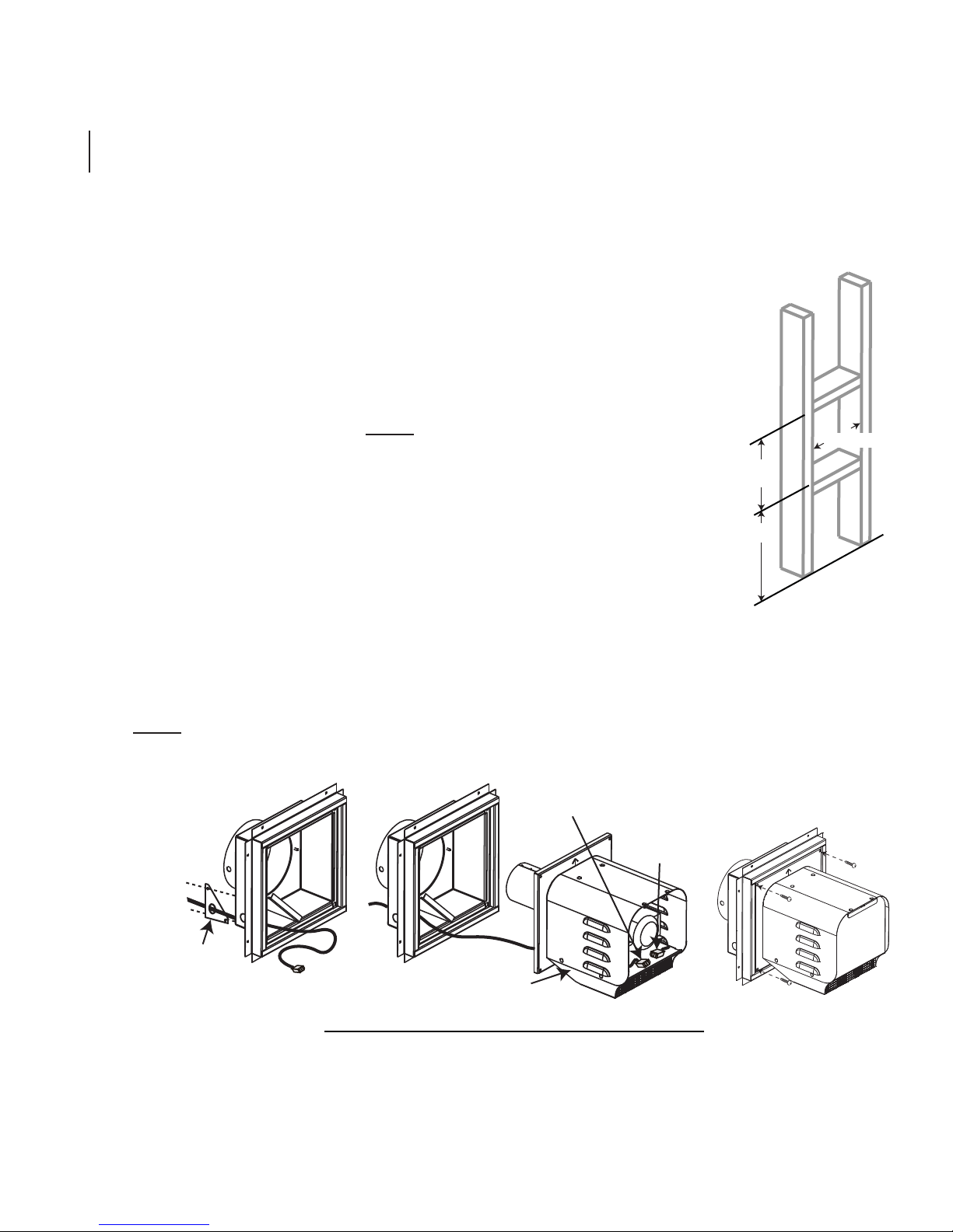
1.4.1 TERMINAL INSTALLATION
This application occurs when venting through an exterior wall. Having determined the correct
height for the terminal location, cut and frame a hole in the exterior wall as illustrated to accommodate the GPV.
A. Remove the electrical access plate from the frame assembly, then remove the
knock out from this plate.
B. Insert the wiring through the electrical access plate and engage the conduit bush-
ing. Re-secure this plate. NOTE: The GPV includes a 20 foot wire
harness cable. If this cable does not reach the appliance, then it
may be cut and a splice added. These connections must conform
with local codes or, in the absence of local codes, use the current CSA
C22.1 Canadian Electrical Code in Canada or the ANSI/NFPA 70
National Electrical Code in the United States.
5
10 1/4”
11 1/4”
C. Remove terminal access cover, see “INSTALLATION OVERVIEW” for
location and route cable through terminal.
D. Assemble gas power vent terminal to frame assembly.
E. Connect the male and female connectors.
F. Replace terminal access cover.
NOTE: Where possible, it is strongly recommended to have an access panel inside the building for
servicing the unit.
MALE MOLEX
ELECTRICAL
ACCESS PLATE
CONNECTOR
TERMINAL
FEMALE
MOLEX
CONNECTOR
20.4
W415-0682 / D / 02.06.12
Page 6

6
1.4.2 POWER VENT INSTALLATION
A. Stretch the inner fl ex pipe to the required length taking
into account the additional length needed for the fi n-
ished wall surface. Slip the vent pipe a minimum of 3”
over the inner sleeve of the terminal and secure with 3
#8 screws. Apply a heavy bead of the high temperature
sealant W573-0007 Mill Pac (not supplied).
B. Using the outer fl ex pipe, slide over the outer combus-
tion air sleeve of the terminal and secure with 3 #8
screws. Seal using high temperature sealant W5730002 (not supplied).
CAULKING
TERMINAL
FIRESTOP
SPACER
C.
D. Route venting through framed opening and fi restop spacer to the
E. The terminal mounting plate may be recessed into the exterior
F. If more vent pipe needs to be used to reach the appliance, couple
G. Install the reducer (if required) or vent and properly secure and
Apply a bead of caulking (not supplied) to the framed
opening and secure the terminal. Ensure the arrows
stamped into the frame assembly are pointing upwards.
NOTE: For fi restop spacer installation instructions,
see PVA kit or the appliance Installation Manual.
appliance.
wall or siding no greater than the depth of its return fl ange.
them together as illustrated. The vent system must be supported
approximately every 3 feet for both vertical and horizontal runs.
Use noncombustible strapping to maintain the minimum clearance
to combustibles.
seal to the unit using high temperature sealant
W573-0007 Mill Pac (not supplied).
HI-TEMP
SEALANT
#10 X 2”
SCREWS
HIGH
TEMPERATURE
SEALANT
RETURN
FLANGE
#8 X 1/2” SELF DRILLING
SCREWS & WASHERS
INNER COUPLER
OUTER COUPLER
1.4.3 INITIAL FIRING PROCEDURES
ALWAYS LIGHT THE PILOT WHETHER FOR THE FIRST TIME OR IF THE GAS SUPPLY HAS RUN OUT
WITH THE GLASS DOOR OPENED OR REMOVED. PURGE SHOULD BE PERFORMED BY A QUALI-
FIED SERVICE TECHNICIAN. ASSURE THAT A CONTINUOUS GAS FLOW IS AT THE BURNER BE-
FORE CLOSING THE DOOR. ENSURE ADEQUATE VENTILATION.
In some instances the system may not light pilot/burner with the door open/removed. Partially blocking the
exhaust fl ue collar will allow the safety pressure switch to activate and allow gas fl ow to the pilot during the
initial test fi ring.
W415-0682 / D / 02.06.12
OUTER
FLEX PIPE
!
WARNING
OUTER
FLEX PIPE
INNER
FLEX PIPE
23.6
Page 7

1.4.4 ELECTRICAL CONNECTION
DO NOT USE THIS APPLIANCE IF ANY PART HAS BEEN UNDER WATER. CALL A QUALIFIED
SERVICE TECHNICIAN IMMEDIATELY TO HAVE THE APPLIANCE INSPECTED FOR DAMAGE TO THE
RISK OF ELECTRICAL SHOCK OR EXPLOSION. DO NOT WIRE 110V TO THE VALVE OR TO THE
APPLIANCE WALL SWITCH. INCORRECT WIRING WILL DAMAGE CONTROLS.
ALL WIRING SHOULD BE DONE BY A QUALIFIED ELECTRICIAN AND SHALL BE IN COMPLIANCE
WITH LOCAL CODES. IN THE ABSENCE OF LOCAL CODES, USE THE CURRENT CSA22.1 CANADIAN
ELECTRIC CODE IN CANADA OR THE CURRENT NATIONAL ELECTRIC CODE ANSI/NFPA NO. 70 IN
ALWAYS LIGHT THE PILOT WHETHER FOR THE FIRST TIME OR IF THE GAS SUPPLY HAS RAN OUT,
WITH THE GLASS DOOR OPENED OR REMOVED.
1.4.5 HARD WIRING CONNECTION
It is necessary to hard wire this appliance.
Permanently framing the appliance with an enclosure, requires the appliance junction box to be hard wired.
This appliance must be electrically connected and grounded in accordance with local codes. In the absence
of local codes, use the current CSA C22.1 Canadian electrical code in Canada or the ANSI/NFPA 70-1996
national electrical code in the United States.
!
WARNING
ELECTRICAL CIRCUIT.
THE UNITED STATES.
7
69.2
1.4.6 RECEPTACLE WIRING DIAGRAM
ELECTRICAL BOX
(BLACK)
3 PRONG
RECEPTACLE
(WHITE)
GROUND
(GREEN)
WIRE
NUTS
L1 (BLACK)
GROUND
(GREEN)
L2 (WHITE)
CABLE
CONNECTOR
SCREW
ELECTRICAL
BOX COVER
W415-0682 / D / 02.06.12
Page 8

8
1.4.7 ELECTRICAL BOX INSTALLATION
NOTE: Before fi nishing in the appliance, the power vent must be installed.
POWER VENT
CONTROL
MODULE
LHD50 ILLUSTRATED
BX SNAP
BUSHING
20’ POWER
VENT CABLE
CONTROL MODULE
A. Start by removing the pre-fi nishing access panel or opening lower louvre.
B. Position the Power Vent Control Module in a convenient location (not on top of the heat shield in the
LHD50) and Velcro it to the base of the appliance.
C. Slide the 20’ power vent cable through the right side of the appliance and connect the box connector to
the side panel, see “INSTALLATION OVERVIEW” section for illustration.
D. Feed the wires through the inside panel, slide the split bushing over the coated wires and snap into
the 7/8” hole to protect the wires as illustrated. Attach the connections as per the appropriate wiring
diagram. See “WIRING DIAGRAM AND INSTALLATION” section.
E. Plug the power vent control module into either the appliance junction box or the control module, if
equipped.
JUNCTION BOX
SPLIT BUSHING
REQUIRED
W415-0682 / D / 02.06.12
Page 9

1.5 RESTRICTOR PLATE INSTALLATION
REFER TO PVA KIT FOR APPLIANCE SPECIFIC INSTRUCTIONS.
1.6 WIRING DIAGRAM AND INSTALLATION
Connect the wiring to the power vent termination as outlined in the previous section, and connect the wiring
to the appliance as outlined in the schematic below. Ensure that the proper clearances are maintained for the
wiring and conduit. When installing the wiring it must never run above the vent run and it must be a minimum 1”
from all venting.
NOTE: The GPV includes a 20 foot wire harness. If this harness does not reach the appliance, then it
may be cut and a splice added. These connections must conform with local codes or, in the absence
of local codes, use the current CSA C22.1 Canadian Electrical Code in Canada or the ANSI/NFPA 70
National Electrical Code in the United States.
1.6.1 SIT IPI 885 PROFLAME COMPLETE WITH GPV POWER VENT TERMINAL
1. Disconnect the wires labeled ON/OFF (White/Green) and TH (Green). Reconnect them to the
corresponding male/female connectors on the Power vent control module.
2. Disconnect the two D/C (Red/Black) wires from each other and reconnect them to the corresponding D/C
connectors on the Power vent control module.
9
3. Disconnect the Orange wire from the gas valve and reconnect it to the Yellow wire (female connector) from
the Power vent control module.
4. Connect the remaining Yellow wire (male connector) from the Power vent control module to the tab on the
gas valve where the Orange wire was removed.
W415-0682 / D / 02.06.12
Page 10

10
BLOWER
WHITE
BLACK
GREEN
VAC SWITCH
YELLOW
YELLOW
1
GPV Terminal
Receiver
120 VOLT FAN AUX OUT
INTO
PLUG
120 VOLT
RED / FCM-COM
GREY / FCM-COM
PURPLE / FCM-COM
GREEN / TH
RED / DC SUPPLY
PINK
BLUE
BLACK / DC SUPPLY
BROWN / MOTOR
BLACK / MOTOR
YELLOW / MOTOR
ORANGE / MOTOR
SPLIT FLOW
(IF INCLUDED
WITH APPLIANCE)
POWER
COM
Control
Module
Vent
Power
Control
Module
Pull connectors apart to
connect to power vent
2
IPI Board
FLAME
SENSOR
BLACK 3/16
BLACK 1/8
CONNECTION
GREEN / ON/OFF
RED / DC SUPPLY
CONNECTION
YELLOW / GREEN
WHITE / TPTH
IMPORTANT: IF USED,
RED
BLACK
WHITE
BLACK / DC SUPPLY
BLACK
YELLOW / GREEN
IT MUST BE
CONNECTED TO A 6
VOLT BATTERY PACK,
HOWEVER MUST NOT
BE USED WHEN USING
THE REMOTE
CONTROL RECEIVER
SWITCH
IPI / CPI (ACS)
(MUST BE DISABLED IF THERE IS
ANY DOWNWARD VENTING.)
GREEN
ORANGE
3
YELLOW
YELLOW
4
SIT Valve
Pilot Assembly
SPARK
ELECTRODE
W415-0682 / D / 02.06.12
Electronic Ignition
TUBE
Page 11

11
1.6.2 SIT MILLIVOLT 820 NOVA COMPLETE WITH GPV POWER VENT TERMINAL
NOTE: Must use double pole switch (supplied) or double pole thermostat (not supplied) with specifi c
power vent adaptor kit.
NOTE: Downward venting is not allowed with appliances that use a standing pilot.
1. Connect the jumper wires to tabs TP/TH and TH on the gas valve.
2. Connect the jumper wire to the two Yellow wires from the Power vent control module.
PILOT
THERMOPILE
BURNER
Pilot Assembly
BLOWER
BLACK
WHITE
GREEN
THERMOCOUPLE
RED
WHITE
SIT Millivolt Gas Valve
JUMPER
1
2
YELLOW
YELLOW
VAC SWITCH
YELLOW
YELLOW
GPV Terminal
IMPORTANT: A RECEPTACLE MAY NEED TO BE INSTALLED AS A POWER SOURCE FOR THE GPV.
GREEN
RED
ORANGE
Double Pole
Switch
WHITE
BLACK
Power Vent
Control
Module
Appliance
Junction Box
W415-0682 / D / 02.06.12
Page 12

12
1.6.3 SIT IPI 880/886 PROFLAME COMPLETE WITH GPV POWER VENT TERMINAL
NOTE: Must use double pole switch (supplied) or double pole thermostat (not supplied) with specifi c
power vent adaptor kit.
1. Connect the jumper wires to the wire labeled ON/OFF (Green/White) and the wire labelled TH (Green).
2. Connect the other end of the jumper wires to the Yellow wires from the Power vent control module.
DC BACK-UP
(NOT ALLOWED
WITH GPV
INSTALLATION)
-
+
+
-
TRANSFORMER
ACS/IPI
SWITCH
(OPTIONAL)
DC SUPPLY
IPI / CPI
1
GROUND
JUMPER
GROUND
EYELET
VALVE
ORANGE
GREEN
VALVE
ELECTRONIC
IPI BOARD
DFC
VAC SWITCH
BLOWER
BLACK
WHITE
GREEN
YELLOW
YELLOW
GPV Terminal
2
YELLOW
YELLOW
Power
Vent
Control
Module
GREEN
RED
ORANGE
WHITE
BLACK
Double Pole
Switch
Appliance
Junction Box
IMPORTANT: A receptacle may need to be
installed as a power source for the GPV.
W415-0682 / D / 02.06.12
Page 13

1.6.4 DEXEN IPI 6003-3V COMPLETE WITH GPV POWER VENT TERMINAL
NOTE: Must use double pole switch (supplied) or double pole thermostat (not supplied) with specifi c
power vent adaptor kit.
NOTE: Downward venting is not allowed with appliances that use a standing pilot.
1. Connect the Brown wires from the Ignition module to the yellow wires from the Power vent control
module.
Battery
Holder
BLACK
Ignition Module
BLUE
BLUE
Ignitor
ORANGE
YELLOW
ORANGE
13
RED
Battery
Relay
VAC SWITCH
BLACK
YELLOW
BROWN
BROWN
BLOWER
BLACK
WHITE
GREEN
YELLOW
YELLOW
GPV Terminal
BLACK
GREEN
1
GREEN
Dexen Gas Valve
YELLOW
YELLOW
Power
Vent
Control
Module
IMPORTANT: A receptacle may need to be installed as a power source for the GPV.
RED
ORANGE
WHITE
Double Pole
Switch
BLACK
Appliance
Junction Box
W415-0682 / D / 02.06.12
Page 14

14
1.6.5 SIT REMOTE CONTROLLED MILLIVOLT SYSTEM COMPLETE WITH GPV
POWER VENT TERMINAL
NOTE: Must use double pole switch (supplied) or double pole thermostat (not supplied) with specifi c
power vent adaptor kits.
NOTE: Downward venting is not allowed with appliances that use standing pilots.
PILOT
THERMOPILE
BURNER
Pilot Assembly
Receiver
BLOWER
BLACK
WHITE
GREEN
THERMOCOUPLE
RED
WHITE
SIT Millivolt Gas Valve
JUMPER
1
2
YELLOW
YELLOW
VAC SWITCH
YELLOW
YELLOW
GPV Terminal
1. Disconnect one of the two wires from the receiver to the valve. Connect it to one of the yellow
wires from the power vent control module.
2. Connect a jumper wire to the valve where the receiver wire was disconnected and to the other yellow
wire from the power vent control module.
W415-0682 / D / 02.06.12
GREEN
RED
ORANGE
Double Pole
Switch
WHITE
BLACK
Power Vent
Control
Module
Appliance
Junction Box
Page 15

2.0 ADJUSTMENTS
2.1 VENTURI ADJUSTMENTS
REFER TO PVA KIT FOR SPECIFIC APPLIANCE INSTRUCTIONS.
3.0 REPLACEMENTS
Contact your dealer or the factory for questions concerning prices and policies on replacement parts. Normally
all parts can be ordered through your Authorized dealer / distributor.
FOR WARRANTY REPLACEMENT PARTS, A PHOTOCOPY OF THE ORIGINAL INVOICE WILL BE
REQUIRED TO HONOUR THE CLAIM.
When ordering replacement parts always give the following information:
• Model & Serial Number of appliance
• Installation date of appliance
• Part number
• Description of part
• Finish
* IDENTIFIES ITEMS WHICH ARE NOT ILLUSTRATED. FOR
FURTHER INFORMA TION, CONTACT YOUR AUTHORIZED DEALER.
15
!
WARNING
FAILURE TO POSITION THE PARTS
IN ACCORDANCE WITH THIS
MANUAL OR FAILURE TO USE ONLY
PARTS SPECIFICALLY APPROVED
WITH THIS APPLIANCE MAY
RESULT IN PROPERTY DAMAGE OR
PERSONAL INJURY.
41.1
COMPONENTS
REF GPV PART NO. DESCRIPTION
1 W062-0026 BLOWER
2 W660-0056 SWITCH, VACUUM
3* W750-0195 WIRE HARNESS, TERMINAL
4* W750-0209 20’ WIRE HARNESS CABLE FROM UNIT TO TERMINAL
5 W010-1924PW PEWTER MAIN BODY
6 W010-1925PW PEWTER FRAME
7 W290-0138 BLOWER GASKET
8 W500-0400 BLOWER MOUNTING PLATE
9 W200-0256PW PEWTER ACCESS COVER
10 W500-0419 DILUTION AIR PLATE
11* W345-0008 HOSE
5
8
7
6
1
9
2
10
W415-0682 / D / 02.06.12
Page 16

16
4.0 TROUBLESHOOTING
ALWAYS LIGHT THE PILOT WHETHER FOR THE FIRST TIME OR IF THE GAS SUPPLY HAS RAN OUT,
WITH THE GLASS DOOR OPEN OR REMOVED.
IN SOME INSTANCES THE SYSTEM MAY NOT LIGHT PILOT/BURNER WITH THE DOOR OPEN/
REMOVED. PARTIALLY BLOCKING THE EXHAUST FLUE COLLAR WILL ALLOW THE SAFETY
PRESSURE SWITCH TO ACTIVATE AND ALLOW GAS FLOW TO THE PILOT DURING THE INITIAL
SYMPTOM PROBLEM TEST SOLUTION
Main burner fl ame is
a blue lazy transparent fl ame.
Carbon is being
deposited on glass or
combustion chamber
surfaces.
White / Grey fi lm
forms.
Exhaust fumes
smelled in room,
headaches.
Main burner will not
light.
Main burner fl ames
are very aggressive.
Main burner won’t
light.
Leak in exhaust vent. - Check exhaust vent pipe and all connection seals.
Incorrect installation. - Refer to PVA kit for appliance specifi c restrictor.
Air shutter has become blocked
or incorrect setting.
Flame is impinging on the logs
or combustion chamber.
Sulphur from fuel is being deposited on glass, logs or combustion chamber surfaces.
Appliance is spilling. - Check door seal and relief fl ap seal.
Main door is not installed. - Install main door.
No restrictor. - Add restrictor.
Vacuum switch not activated. - Remove blockage. In really cold conditions, ice
!
WARNING
TEST FIRING.
- Ensure air shutter opening is free of lint or other
obstructions or has correct setting.
- Check that the media is correctly positioned.
- Open air shutter to increase the primary air.
- Check the input rate: Check the manifold
pressure and orifi ce size as specifi ed by the rating
plate values.
- Check that the door gasket is not broken or
missing and that the seal is tight.
- Check that both 4" and 7" vent liners are free of
holes and well sealed at all joints.
- Check that the proper restrictor is used
- Clean the glass with a gas appliance glass
cleaner. DO NOT CLEAN GLASS WHEN HOT.
- If deposits are not cleaned off regularly, the glass
may become permanently marked.
- Check for proper restrictor.
- Check that the paint curing process is complete.
- Remove restrictor plate on the power vent.
buildup may occur on the terminal and should be
removed as required.
- Test vacuum switch and replace as required.
IMPORTANT: Prove all systems check before completely enclosing unit.
W415-0682 / D / 02.06.12
 Loading...