

Page 1
F-40 AND F-50 TRANSMITTER UNIT
INSTALLATION AND OPERATION INSTRUCTIONS
F-40 Includes: F-50 Includes:
W660-0066 Transmitter W660-0067 Transmitter
W660-0076 Receiver W660-0076 Receiver
The F-40 and the F-50 transmitter units have been approved for
use with most Wolf Steel gas fi replaces using a millivolt system.
The Receiver (W660-0076) can be installed in either the fi replace
or be wall mounted depending on the application.
The F-40 provides on/off status, and the current room temperature
as well as having a low battery indicator. It allows you to switch the
fi replace on or off from anywhere in the room.
The F-50 is a thermostatically controlled transmitter that provides
on/off status, displays room/set temperature as well as having a
low battery indicator. These transmitter kits are tested and safe
when installed in accordance with these instructions.
Modifi cation of any part of this kit will void any warranty claims
and could create a fi re hazard.
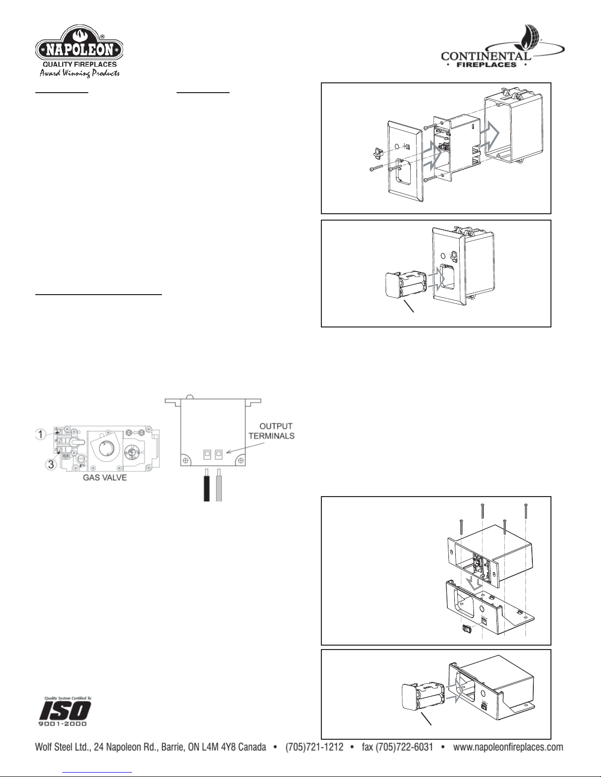
RECEIVER INSTALLATION:
Turn off the electrical power and the gas supply to the fi replace.
(Gas supply may need to be disconnected from the gas control
valve.) Make sure the slide switch on the receiver is set to the OFF
position.
1. Either disconnect or connect in parallel* with any other
transmitter wiring from the valve. Attach the wires from terminal 1
(TPTH) and terminal 3 (TH) of the gas valve to the output terminals
on the receiver.
WALL MOUNT
EXPLODED VIEW
O
SLIDE
SWITCH
N
RE
M
OT
BA
E
T.LOW
OFF
JUNCTION
FIREPL
ACE
REM
OT
E
RECEIVER
BOX
FACEPLATE
WALL MOUNT
UN-EXPLODED VIEW
PRE
SS
T
O OPE
N
BATTERY
COMPARTMENT
FIREPLACE MOUNT:
For stove and insert models: do not install the receiver in the
gas control valve compartment as this area becomes too hot. On
stoves, it may be installed in or behind the pedestal; on inserts,
it may be installed behind the fl ashings or a similar convenient
location.
In a zero clearance model: the receiver may be installed in the
gas control compartment.
2. Ensuring that the mounting location will allow for the battery
compartment to slide out, secure the receiver to an appropriate
location depending on the fi replace model using the screws
provided and/or the adhesive pad.
3. If the gas supply was disconnected at the valve, leak test using
a soap and water solution. Turn electricity back on.
ON
R
E
M
O
T
BA
E
T
.
L
O
W
OF
F
FIR
EPLA
C
E
R
EM
O
TE
*INSTALLER: It may be advisable to connect a switch with
short lengths of wire to minimize the resistance. This will allow
the homeowner to continue to control the burner in the event
of battery failure.
For all millivolt switch wiring, hook up the switch leads on
terminals 1 and 3 of the gas valve.
WALL MOUNT:
2. Press the battery compartment slightly into the receiver and
release enabling the battery compartment to pop out. Pull off the
slide switch. Slide the receiver out of the fi replace mounting plate.
3. Using the screws provided secure the receiver and the face
plate to an existing junction box.
4. Replace the slide switch. Place 4 AA batteries into the battery
compartment and slide the compartment back
into the receiver.
5. If the gas supply was disconnected at
the valve, leak test using a soap and water
W415-0628 / 11.20.07
solution. Turn electricity back on.
FIREPLACE MOUNT
EXPLODED VIEW
RECEIVER
FIREPLACE
MOUNTING PLATE
FIREPLACE MOUNT
UN-EXPLODED VIEW
PRE
SS
T
O OPEN
COMPARTMENT
SLIDE
SWITCH
BATTERY
B
A
T.
LO
W
OFF
REMO
TE
O
N
B
A
T
.LO
W
O
FF
REMO
TE
O
N
Page 2
TRANSMITTER WALL MOUNT:
Secure to the desired wall location using
screws, and anchors if required.
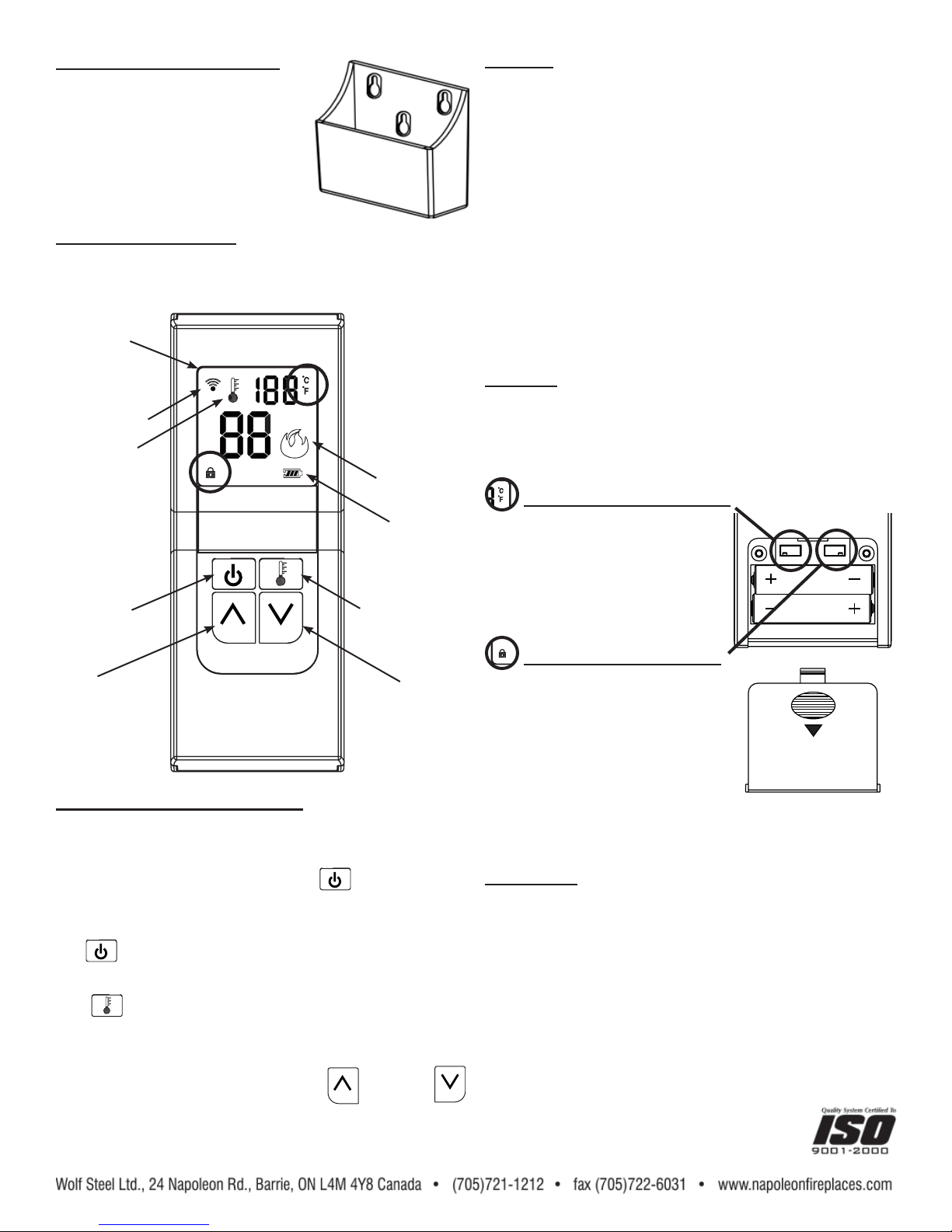
RECEIVER OPERATION:
The receiver switch must be in the TRANSMITTER position for the
transmitter to function.
LCD
DISPLAY
SIGNAL
INDICATOR
THERMOSTAT
BULB
FLAME
INDICATOR
LOW
BATTERY
INDICATOR
CAUTION: In the event that the transmitter fails to send a
signal to the receiver for a period of twenty-four hours, the
receiver will automatically turn OFF the fi replace. This may
occur if the set temperature is not reached, if the transmitter is
out of range (25 feet), or if the transmitter batteries fail.
The twenty-four hour safety timer allows the receiver to
assume control of the fi replace after two hours of uninterrupted
operation. After two hours of continuous operation by the
fi replace the receiver will cycle OFF for 30 minutes and ON for
20 minutes for the next four hours.
If a signal has not been received after twenty-four hours the
receiver will shut OFF the fi replace. Press the AUTO ON/OFF
button on the transmitter to reset the transmitter, then press
the AUTO ON/OFF button again to resume operation.
The six hour safety timer may be disengaged by moving the
toggle switch on the back of the receiver. Factory setting
is ON. Changing the switch will allow the fi replace to run
continuously if required.
WARNING: In the event of prolonged absences, the F-50
should not be left in thermostat mode. If the transmitter
batteries fail while the fi replace is operating the receiver will
assume control and shut OFF the fi replace after twenty-four
hours. If the transmitter batteries fail while the fi replace is not
operating the fi replace will remain OFF.
TRANSMITTER
TEMPERATURE FUNCTION:
REVIEW VIEW
Remove the battery cover on the back
of the transmitter to expose the °C/°F
dip switch. Move the dip switch to your
desired temperature mode.
°F °C
C/P
AAA
ON / OFF
BUTTON
UP
BUTTON
THERMOSTAT
BUTTON
DOWN
BUTTON
F-50 THERMOSTATIC FUNCTION:
Thermostatic control automatically cycles the fi replace on and off to
maintain the desired room temperature.
To turn the fi replace burner on, press the
The LCD will display the word “ON” and the fl ame indicator will be
shaded in.
The
(ON/OFF) button is used to turn the fi replace on or off
only. It does not set temperature.
The (THERMOSTAT) button is used to control room
temperature. Once pushed, “ON” lights up next to the thermostat
bulb located in the top left corner of the LCD screen.
Set desired room temperature using the
(DOWN) buttons. If the temperature of the room exceeds the
desired room temperature, the thermostat will automatically turn
the fi replace “OFF”.
(ON/OFF) button.
(UP) and
Selected mode will appear in the right
AAA
corner beside the room temperature.
CHILD-PROOF FUNCTION:
1. Remove the battery cover at the
back of the transmitter to expose the
child-proof dip switch.
2. Slide the child-proof dip switch
to position marked C/P to activate the
child-proof function. A lock symbol will
BATTERY COVER
appear in the bottom left corner when
the child-proof function is activated.
3. In child-proof mode the transmitter will not operate the Receiver
until the switch is returned to the other position.
BATTERIES:
The transmitter uses 2 AAA batteries. The receiver uses 4 AA
batteries. Batteries should be replaced at least every 6 months or
when the low battery indicator is lit on the receiver or the transmitter
LCD. Use alkaline batteries only.
TO CHANGE BATTERIES:
Receiver: Slide the switch to OFF. Press the battery compartment
slightly into the receiver and release enabling the battery
compartment to pop out. After removing the original batteries, wait
at least 1 minute before replacing with fresh batteries.
Transmitter: Gently press and slide the battery cover from the
rear surface of the transmitter. After removing
the original batteries, wait at least 1 minute before
replacing with fresh batteries.
W415-0628 / 11.20.07
Page 3

IN THE EVENT OF POWER FAILURE:
If the receiver batteries fail, the fi replace will no longer cycle on
or off, remaining in the current operating mode. To operate the
fi replace in the event of a power/battery failure, the on/off switch
located on the fi replace, if connected, may be used manually. See
“Receiver Installation” instructions for the installer.
CANADIAN EQUIPMENT REQUIREMENTS:
This digital apparatus does not exceed the (Class A / Class
B) limits for radio noise emissions from digital apparatus set
out in the Radio Interference Regulations of the Canadian
Department of Communication. This device complies with
RSS-210 of Industry and Science Canada. Operation is subject
to the following two conditions: (1) this device may not cause
interference, and (2) this device must accept any interference,
including interference that may cause undesired operation of
the device.
FCC REQUIREMENTS:
WARNING: Changes or modifi cations to this unit not expressly
approved by the party responsible for compliance could void
the user’s authority to operate the equipment.
NOTE: This equipment has been tested and found to comply
with the limits for a Class B digital device, pursuant to Part
15 of the FCC Rules. These limits are designed to provide
reasonable protection against harmful interference in a
residential installation. This equipment generates, uses and
can radiate radio frequency energy and, if not installed and
used in accordance with the instructions, may cause harmful
interference to radio communications. However, there is
no guarantee that interference will not occur in a particular
installation. If this equipment does cause harmful interference
to radio or television reception, which can be determined by
turning the equipment off and on, the user is encouraged to
try to correct the interference by one or more of the following
measures:
- Reorient or relocate the receiving antenna.
- Increase the separation between the equipment and
receiver.
- Consult the dealer or an experienced radio TV technician
for help.
W415-0628 / 11.20.07
 Loading...