

Napoleon EPI 1101, EP 1402 Installation And Operating Instructions Manual
INSTALLER: LEAVE THIS MANUAL WITH THE APPLIANCE.
CONSUMER: RETAIN THIS MANUAL FOR FUTURE REFERENCE.
INSTALLATION AND
OPERATING INSTRUCTIONS
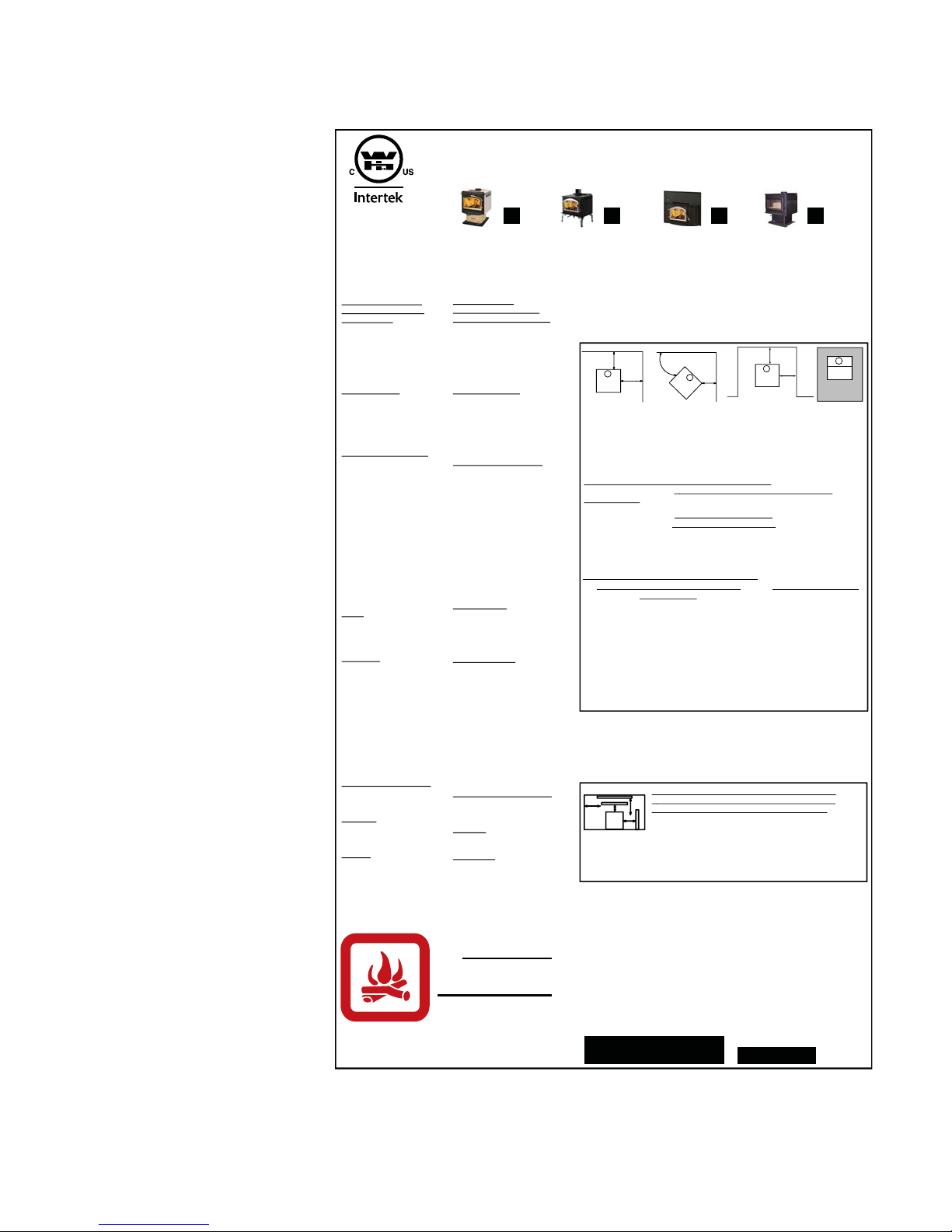
CERTIFIED UNDER U.S. ENVIRONMENTAL PROTECTION AGENCY (E.P.A.) JULY 1990 40 C.F. R. PART 60 AND THE OREGON DEPARTMENT OF
ENVIRONMENTAL QUALITY (D.E.Q.) PARTICULATE EMISSION STANDARDS BY E.E.M.C THESE STOVES HAVE BEEN TESTED AND LISTED BY INTERTEK
TESTING SERVICES TO STANDARDS: CSA B366.2, ULC S627, M2000 UL 1482. MODEL 1100 HAS BEEN TESTED AND LISTED FOR INSTALLATION IN MOBILE
HOMES.
EPI 1101 & 1402
WOOD INSERT
1
SAFETY INFORMATION
!
WARNING
If the information in these instructions is not followed exactly, a
fi re or explosion may result causing property damage, personal
injury or death. Improper installation, adjustment, alteration,
service or maintenance can cause injury or property damage,
bodily injury or even death. Please read entire manual before
you install and use your appliance.
This appliance has not been tested with an unvented gas log
set. To reduce risk of fi re or injury, do not install an unvented
gas log set into the appliance.
- This appliance can be very hot when burning.
- Combustible materials such as fi rewood, wet clothing, etc. placed too
close can catch fi re.
- Children and pets must be kept from touching the appliance when it is hot.
- The chimney must be sound and free of cracks. Before installing this unit,
contact the local building or fi re authority and follow their guidelines.
- Operate only with the door tightly closed.
- Burn wood behind the log retainer directly on the fi rebricks.
- Do not use an elevated grate or otherwise raise the fi re.
- At least 14 square inches of outside air must be admitted to the room or
directly to the unit through a 4” diameter pipe.
- This appliance is designed to burn natural wood only. Higher effi ciencies
and lower emissions generally result when burning air dried seasoned
hardwoods, as compared to softwoods or to green or freshly cut
hardwoods.
- Do not start a fi re with chemicals or fl uids such as gasoline, engine oil,
etc.
- Do not burn treated wood, coal, charcoal, colored paper, cardboard,
solvents or garbage.
- Do not let the appliance become hot enough for any part to glow red.
- KEEP THE STOVE TOP TEMPERATURE BELOW 700°F (371°C). Attempts to
achieve heat output rates that exceed design specifi cations can result in
steel distortion and damage.
1402 Illustrated
Wolf Steel Ltd., 24 Napoleon Rd., Barrie, ON, L4M 4Y8 Canada /
103 Miller Drive, Crittenden, Kentucky, USA, 41030
Phone (705)721-1212 • Fax (705)722-6031 • www.napoleonfi replaces.com • ask@napoleonproducts.com
$10.00
1.7A
W415-0764 / 03.29.10

2
TABLE OF CONTENTS
1.0 INSTALLATION OVERVIEW 3
2.0 INTRODUCTION 4
3.0 INSTALLATION PLANNING 9
4.0 INSTALLATION 10
5.0 FINISHING 13
6.0 OPERATION 16
8.0 MAINTENANCE 20
9.0 REPLACEMENTS 26
10.0 TROUBLE SHOOTING 28
11.0 WARRANTY 29
12.0 SERVICE HISTORY 30
13.0 NOTES 31
2.1 DIMENSIONS 5
2.1.1 1101 DIMENSIONS (COMPLETE WITH FLASHING) 5
2.1.2 1402 DIMENSIONS (COMPLETE WITH FLASHING) 5
2.2 SPECIFICATIONS 5
2.3 GENERAL INSTRUCTIONS 6
2.4 GENERAL INFORMATION 6
2.5 RATING PLATE LOCATION 8
3.1 MINIMUM CLEARANCE TO COMBUSTIBLES 9
4.0.1 TYPICAL EXISTING MASONRY 11
4.0.2 FACTORY BUILT FIREPLACE 12
4.1 LOW CLEARANCE FLUE CONNECTOR (1402) 12
5.1 BRICKS AND BAFFLES INSTALLATION 13
5.2 DOOR REMOVAL / INSTALLATION 14
5.3 DOOR HANDLE INSTALLATION 14
5.4 FLASHING INSTALLATION 15
6.1 BLOWER 17
6.2 AIR CONTROL 18
6.3 FIRE EXTINGUISHERS / SMOKE DETECTORS 18
6.4 FUEL 18
6.5 LIGHTING A FIRE 19
6.5.1 FLASH FIRE 19
6.5.2 EXTENDED FIRE 19
6.6 SMOKING 19
7.1 ASH REMOVAL PROCEDURES 20
7.2 CREOSOTE FORMATION AND REMOVAL 20
7.3 RUNAWAY OR CHIMNEY FIRE 21
7.4 CHIMNEY CLEANING 21
7.5 GLASS REPLACEMENT 22
7.6 GASKET REPLACEMENT 22
7.7 CARE OF GLASS 23
7.8 CARE OF PLATED PARTS 23
7.9 BLOWER SERVICE OR REPLACEMENT (1101) 24
7.10 BLOWER SERVICE OR REPLACEMENT (1402) 24
NOTE: Changes, other than editorial, are denoted by a vertical line in the margin.
W415-0764 / 03.29.10
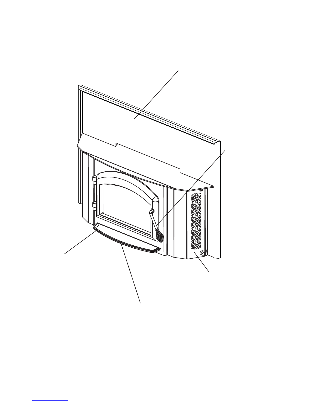
1.0 INSTALLATION OVERVIEW
1402 Illustrated
3
Flashing, see “FLASHING
INSTALLATION” section.
Door, see “DOOR AND
HANDLE INSTALLATION”
section.
Rating plate, see
“RATING PLATE
INFORMATION”
section.
Blower, see “BLOWER INSTALLATION”
section.
Draft, see “AIR CONTROL” section.
W415-0764 / 03.29.10

4
2.0 INTRODUCTION
• THIS APPLIANCE IS HOT WHEN OPERATED AND CAN CAUSE SEVERE BURNS IF CONTACTED.
• Do not operate appliance before reading and understanding operating instructions. Failure to operate
appliance according to operating instructions could cause fi re or injury.
• Before installing this appliance, contact the local building or fi re authority and follow their guidelines.
• This appliance must be installed by a qualifi ed installer.
• Risk of burns. The appliance should be turned off and cooled before servicing.
• Do not let the appliance become hot enough for any part to glow red.
• Do not install damaged, incomplete or substitute components.
• Risk of cuts and abrasions. Wear protective gloves and safety glasses during installation. Sheet metal
edges may be sharp.
• Young children should be carefully supervised when they are in the same room as the appliance. Toddlers, young children and others may be susceptible to accidental contact burns. A physical barrier is
recommended if there are at risk individuals in the house. To restrict access to an appliance or stove,
install an adjustable safety gate to keep toddlers, young children and other at risk individuals out of the
room and away from hot surfaces.
• Clothing or other fl ammable material should not be placed on or near the appliance. Objects placed in
front of the appliance must be kept a minimum of 48” away from the front face of the appliance.
• Due to high temperatures, the appliance should be located out of traffi c and away from furniture and
draperies.
• Ensure you have incorporated adequate safety measure to protect infants/toddlers from touching hot
surfaces.
• Even after the appliance is out, the glass and/or screen will remain hot for an extended period of time.
• Check with your local hearth specialty dealer for safety screens and hearth guards to protect children
from hot surfaces. These screens and guards must be fastened to the fl oor.
• Any safety screen or guard removed for servicing must be replaced prior to operating the appliance.
• Under no circumstances should this appliance be modifi ed.
• Do not operate the appliance with the glass door removed, cracked or broken. Replacement of the glass
should be done by a licensed or qualifi ed service person.
• Do not strike or slam shut the appliance glass door.
• Operate only with the doors tightly closed.
• Only doors / optional fronts certifi ed with the unit are to be installed on the appliance.
• Keep the packaging material out of reach of children and dispose of the material in a safe manner. As
with all plastic bags, these are not toys and should be kept away from children and infants.
• If the appliance is not properly installed, a house fi re may result. Do not expose the appliance to the elements
(ex. rain, etc.) and keep the appliance dry at all times. Wet insulation will produce an odour when the appliance
is used.
• The chimney must be sound and free of cracks. Clean your chimney a minimum of twice a year and as required.
• Do not start a fi re with chemicals or fl uids such as gasoline, engine oil, etc.
• Your appliance requires periodic maintenance and cleaning. Failure to maintain your appliance may lead to
smoke spillage in your home.
• Higher effi ciencies and lower emissions generally result when burning air dried seasoned hardwoods,
as compared to softwoods or too green or freshly cut hardwoods. Burning wet unseasoned wood can
cause excessive creosote accumulation. When this is ignited it can cause a chimney fi re that may result
in a serious house fi re.
• This appliance is designed to burn natural wood only. Do not burn treated wood, coal, charcoal, coloured paper, cardboard, solvents or garbage.
• Burn wood behind the log retainer directly on the fi rebricks. Do not elevate grate or otherwise raise the
fi re.
• Do not store wood within appliance installation clearances or within the space required for re-fueling
and ash removal.
!
WARNING
3.17A
W415-0764 / 03.29.10
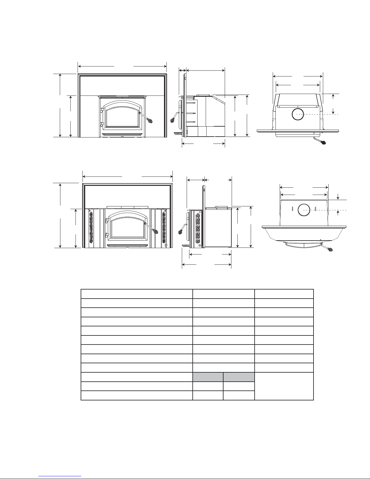
2.1 DIMENSIONS
2.1.1 1101 DIMENSIONS (COMPLETE WITH FLASHING)
5
44 ½”
A*
B*
31 ¼”
21 ½”
20 ½”
21
11
/
16
20 ½”
”
2.1.2 1402 DIMENSIONS (COMPLETE WITH FLASHING)
1
9
/16
44 ½”
31 ¼”
19 ¾”
”
12
3
/16
”
20 ¾”
21 ½”
28”
24”
25
24
11”
1
/2
”
1
/2
”
5 ½”
2.2 SPECIFICATIONS
HEAT OUTPUT (HIGH BURN) ** 55,000 BTU 70,000 BTU
* Figures will vary considerably with individual conditions.
** Wolf Steel Ltd. estimated realistic BTU/h with hardwood logs and regular refueling.
3
21
/8
”
22 ¼”
Specifi cations 1101 1402
CHAMBER (D.W.H) 13 1/2x18x12” 18x18x12”
CAPACITY 1.7 ft
APPROX. AREA HEATED* 600-1600 ft
3
2
2.25 ft
800-2000 ft
DURATION LOW FIRE* 7 Hours 9 Hours
WEIGHT W/O BRICKS 185 lbs 250 lbs
WEIGHT OF BRICKS 110 lbs 145 lbs
IDEAL FUEL SIZE 12” 16”
AB
N/AMIN DEPTH 8” 15”
MAX DEPTH 3 /12” 19 1/2”
3
2
W415-0764 / 03.29.10

6
2.3 GENERAL INSTRUCTIONS
ALL WIRING SHOULD BE DONE BY A QUALIFIED ELECTRICIAN AND SHALL BE IN COMPLIANCE WITH
LOCAL CODES. IN THE ABSENCE OF LOCAL CODES, USE THE CURRENT CSA22.1 CANADIAN
ELECTRIC CODE IN CANADA OR THE CURRENT NATIONAL ELECTRIC CODE ANSI/NFPA NO. 70 IN
THIS APPLIANCE HAS NOT BEEN TESTED WITH ANY VENTED OR UNVENTED GAS LOG SET. TO
REDUCE RISK OF FIRE OR PREVENT INJURY, DO NOT INSTALL A VENTED OR UNVENTED GAS LOG
BURNING YOUR UNIT WITH THE ASH DUMP DOOR OPEN OR AJAR CREATES A FIRE HAZARD THAT
MAY RESULT IN DISCOLOURATION TO THE GOLD PLATED DOOR, INTERNAL DAMAGE TO THE
APPLIANCE OR A HOUSE CHIMNEY FIRE.
DO NOT CONNECT THIS APPLIANCE TO A CHIMNEY FLUE SERVING ANOTHER APPLIANCE.
THIS APPLIANCE AND IT’S COMPONENTS ARE DESIGNED TO BE INSTALLED AND OPERATED AS A
SYSTEM. ANY ALTERATION TO OR SUBSTITUTION FOR ITEMS IN THIS SYSTEM, UNLESS ALLOWED
BY THESE INSTALLATION INSTRUCTIONS, WILL VOID THE LISTING AND MAY VOID THE PRODUCT
WARRANTY. IT MAY ALSO CREATE A HAZARDOUS INSTALLATION. READ THROUGH THESE
INSTRUCTIONS THOROUGHLY BEFORE STARTING YOUR INSTALLATION AND FOLLOW THEM
CAREFULLY THROUGHOUT YOUR PROJECT.
!
WARNING
THE UNITED STATES.
SET INTO THE APPLIANCE.
• Before beginning your installation, consult with your local building code agency or fi re offi cials and
insurance representative to ensure compliance.
• Non-toxic smoke will be emitted during the paint curing process, to help dissipate the smoke open a
window near the appliance.
• Remove any dust or debris off the top of the appliance before fi ring the appliance as the paint will
become soft as the appliance heats up and will harden as the appliance cures. To cure the paint on
your appliance burn your appliance moderately hot during the fi rst few fi res.
• To keep the gasket from sticking to the appliance as the paint is curing, periodically open the door
every 5-10 minutes.
• For the fi rst two weeks use generous amounts of fuel and burn the appliance with the damper wide
open for an hour as the appliance goes through a process of eliminating moisture in the steel and
fi rebricks. The initial heat output will be reduced while the moisture is bring drawn from the appliance
and it will be necessary to build several hot fi res to remove this moisture. DURING THIS PROCESS
DO NOT OVERFIRE THE APPLIANCE. REDUCE THE AMOUNT OF AIR COMING INTO THE
APPLIANCE IF THE APPLIANCE OR CHIMNEY BECOMES RED.
2.4 GENERAL INFORMATION
Your appliance was specifi cally designed to meet the 1990 U.S.A. EPA particulate emission standards and has
been extensively tested in Canadian and American laboratories. This system is the most effi cient, simple and
trouble free we know and works as follows:
4.7
Your appliance is the exact duplication of the clean-burning technology found in all Napoleon EPA certifi ed freestanding
stoves and in particular that of the EPA 1100 and 1400. External modifi cations have been made to allow its installation
as a “functional insert” with a heat circulating blower system and a means of enclosing the solid fuel burning fi replace
cavity for greater heating effi ciency.
W415-0764 / 03.29.10
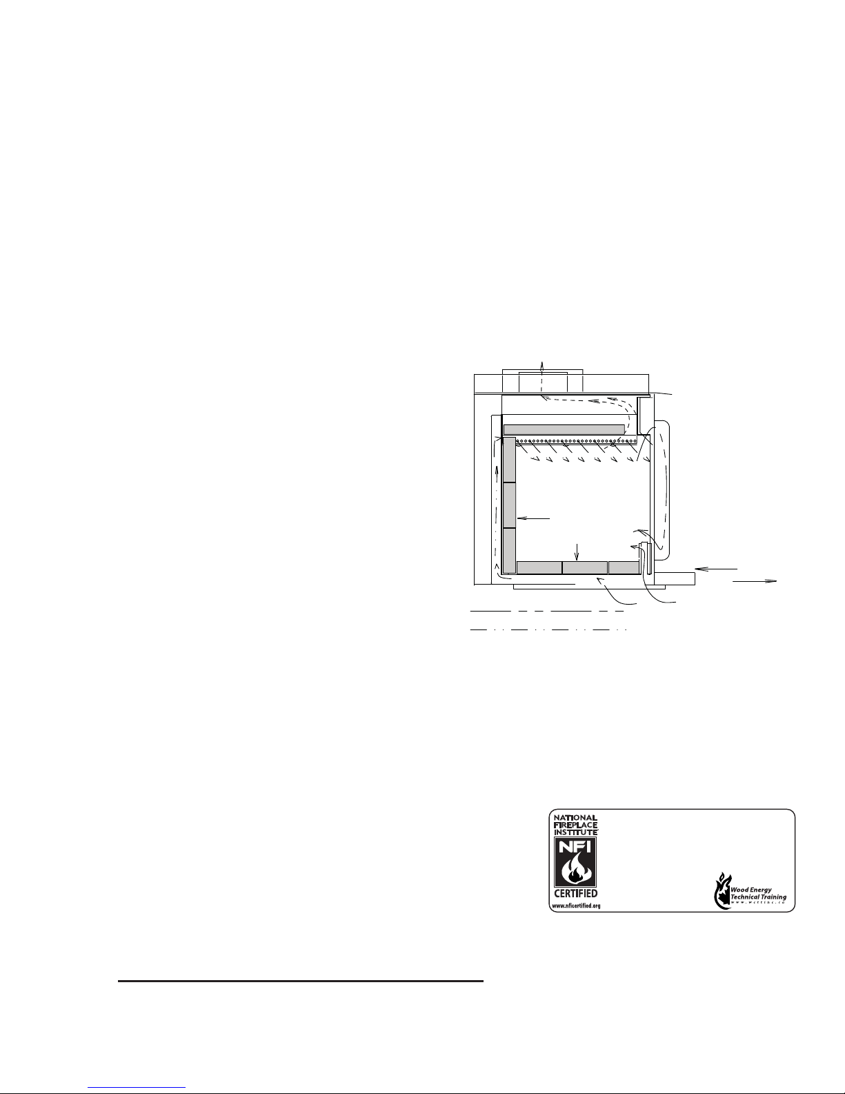
The 1101 insert must be installed into a solid fuel burning fi replace that is at least 16 1/2 inches deep, 28 1/2 inches
HOT SECONDARY AIR
FIBRE BRICKS
REFRACTORY
2 SIDES, BACK
& BOTTOM
SECONDARY AIR
PRIMARY AIR
FLUE GLASS
CERAMIC
GLASS
AIR CONTROL
COMBUSTION AIR
INTAKE
OPEN
CLOSED
We suggest that our woodburning hearth products
be installed and serviced by professionals who are
certified in the U.S. by the National Fireplace
Institue® (NFI) as NFI Woodburning Specialists or
who are certified in Canada by
Wood Energy Technical
Training (WETT).
wide and 22 inches high with an approved lined chimney at least 15 feet high (4.6m) and a hearth of 16”.
Your 1402 insert must be installed only into a solid fuel burning fi replace that is at least 14 inches deep 26 inches
wide and 22 inches high with an approved lined chimney at least 15 feet high (4.6m) and a hearth of 16”. This
minimum recess can only be achieved if the opening height is suffi cient enough to allow the connector to fi t under
the noncombustible facing. The appliance and chimney must be constructed in accordance with all national and local
building code standards.
The chimney vent system used on your wood burning appliance should be designed with the least amount of
restriction possible to enable the exhaust products to easily fl ow through it. Chimney vent systems that are too
short or too long can also have an adverse affect on the fl ow of exhaust through it. The wood burning appliance
and chimney vent system also require a suffi cient supply of combustion air not only to support the combustion in the
combustion chamber but to replace the exhaust leaving it so it can fl ow freely up through the vent system and out
into the atmosphere. It is the correct balance of combustion air and the chimney vent system that will ensure the
appliance provides you with its optimum performance.
Combustion air enters through two holes in the bottom
covered by a single draft control. Air from the front hole
goes up on either side of the door into a preheating
airwash located across the top and then down the
window to feed the fi re and also to ensure that the glass
remains clean. Air from this hole also feeds directly into
the combustion chamber at hearth level. Secondary air
from the rear hole travels up the back in the secondary
air housing to the manifold located at the top and shoots
out laterally to oxidize the gases below the smoke exit.
The combustion chamber is lined with high temperature
fi rebrick on 2 sides, the back and across the bottom,
with a layer of fi bre baffl es at the top to maintain a
high temperature in the combustion chamber so that
gases mixing with the preheated air from the secondary
air manifold tube are easily ignited and burned. The
appliance sides and back are shielded to direct the heat
upwards and forwards into the room.
7
Be sure to provide suffi cient combustion air. There are many other appliances in your home competing for air
such as: a kitchen range hood, forced air heating devices or a bathroom exhaust fan.
Expansion / contraction noises during heating up and cooling down cycles are normal and to be expected.
After extended periods of non-operation such as following a vacation or a warm weather season, the appliance
may emit a slight odour for a few hours. This is caused by dust particles on the fi rebox burning off. Open a
window to suffi ciently ventilate the room.
CALIFORNIA PROP 65 WARNING:
Use of this product may produce smoke which contains chemicals
known to the State of California to cause cancer, birth defects, or
other reproductive harm.
If you experience smoking problems, you may need to open a
door, a window or otherwise provide some method of supplying
combustion air to the appliance.
HINT FOR INSTALLING PORCELAIN ENAMEL INSERTS:
Ensure the base of the porcelain side panels are protected from rubbing against the hearth when sliding your
insert into the masonry fi replace.
W415-0764 / 03.29.10
8
2.5 RATING PLATE LOCATION
For rating plate location, see
“INSTALLATION OVERVIEW”
section.
LISTED SOLID FUEL BURNING SPACE HEATER /
POÊLE À COMBUSTIBLE SOLIDE HOMOLOGUÉ
1400 1400L 1402
ÉMENT
REFERENCE #15982
INSTALL AND USE ONLY IN
ACCORDANCE WITH THE
MANUFACTURER’S
INS TRUC TIONS AND LOCAL
BUILDING COD ES.
MINIMUM CEILING HEIGHT:
7FT (2.13m)
HEARTH EXTENSION /
COMBUSTIBLE FLOOR
PROTECTION: IF INSTALLED
ON A COMBUSTIBLE FLOOR,
UNIT MUST BE PLACED ON A
NON-COMBUSTIBLE FLOOR
PROTECTOR EXTENDING 18”
(455mm) IN FRONT AND 8”
(205mm) TO THE SIDES AND
BACK.
CHIMNEY TYPE: MINIMUM 6”
(152mm) DIAMETER
APPROVED RESIDENTIAL
TYPE FOR MOBILE HOME
USE A CHIMNEY LISTED TO
ULC S629 IN CANADA OR UL
103HT IN THE USA.
CHIMNEY CONNECTOR: 6”
(152mm) DIAMETER MINIMUM
24 GAUGE STEEL MINIMUM
CLEARANCE FROM
HORIZONTAL CONNECTOR
AND CEILING 18” (455mm).
DO NOT OBSTRUCT SPACE
UNDER HEATER.
SPECIAL METHODS ARE
REQUIRED WHEN PASSING A
CHIMNEY THROUGH A WALL
OR CEILING. SEE INSTRUCTIONS AND BUILDING
CODES.
DO NOT CONNECT THIS UNIT
TO A CHIMNEY FLUE
SERVING ANOTHER
APPLIANCE.
FUEL: FOR USE WITH WOOD
ONLY. DO NOT USE GRATE
OR ELEVATE FIRE. BUILD
WOOD FIRE DIRECTLY ON
HEARTH.
WARNING: RISK OF SMOKE
SPILLAGE. OPERATE ONLY
WITH DOOR FULLY CLOSED.
REPLACE GLASS ONLY WITH
CERAMIC GLASS.
DO NOT OVERFIRE. IF
HEATER OR CHIMNEY
CONNECTORS GLOW, YOU
ARE OVERFIRING. INSPECT
AND CLEAN CHIMNEY
FREQUENTLY. UNDER
CERTA IN CONDITIONS OF USE
CREOSOTE BUILD-UP MAY
OCCUR RAPIDLY.
OPTIONAL BLOWER KIT:
EP-62, 115V, 60HZ, 0.82AMP.
ROUTE CORD AWAY FROM
UNIT.
DANGER: RISK OF
ELECTRICAL SHOCK.
DISCONNECT POWER
BEFORE SERVICING UNIT.
INSERT: INSTALL AND USE
ONLY IN SOLID FUEL
BURNING FIREPLACES. DO
NOT REMOVE BRICKS OR
MORTAR FROM SOLID FUEL
BURNING FIREPLACE.
INSTALL WITH A POSITIVE
FLUE CONNECTOR AND
FACEPLATE.
TESTED TO: / TESTÉ SELON : UL1482 / ULC S627 / CSA B366.2 (DEC 92)
POUR INSTALLATION ET
UTILISATION CONFORM
AUX INSTRUCTIONS DU
FABRICANT ET AUX CODES
LOCAUX DU BÂTIMENT.
HAUTEUR DE PLAFOND MINIMAL
7PI (2,13m).
PROLONGEMENT
D’ÂTRE/PROTECTION DU
PLANCHER COMBUSTIBLE: SI
INSTALLÉ SUR UN PLANCHER
COMBUSTIBLE, L’APPAREIL DOIT
ÊTRE PLACÉ SUR UNE PLAQUE
PROTECTRICE INCOMBUSTIBLE
S’ÉTENDANT SUR 18” (455mm)
L’AVANT ET 8” (205mm) À L’ARRIÈRE
ET SUR LES CÔTÉS.
TYPE DE CHIMNÉE: DIAMÈTRE
MINIMAL DE 6” (152mm)
APPROUVÉE POUR USAGE
RÉSIDENTIEL. MAISON MOBILE
EMPLOYEZ UNE CHEMINÉE
HOMOLOGUÉE ULC S629 AU
CANADA OU UL 103HT AUX
ÉTATS-UNIS.
RACCORD DE CHEMINÉE:
DIAMÈTRE DE 6” (152mm) D’ACIER
DE CALIBRE 24 MINIMUM. 18”
(455mm) DE DÉGAGEMENT
MINIMAL ENTRE LE RACCORD
HORIZONTAL ET LE PLAFOND.
NE RIEN ENTREPOSER SOUS
L’APPAREIL.
DES MÉTHODES SPÉCIALES SONT
REQUISES LORSQU’UNE
CHEMINÉE TRAVERSE UN MUR OU
UN PLAFOND. VOIR LES
INSTRUCTIONS ET LES CODES DU
BÂTIMENT.
NE PAS RACCORDER À LA
CHEMINÉE D’UN AUTRE APPAREIL.
COMBUSTIBLE: POUR USAGE
AVEC LE BOIS SEULEMENT.
N’UTILISEZ PAS DE CHENET OU NE
SURÉLEVEZ PAS LE BOIS.
PRÉPAREZ LE FEU DIRECTEMENT
SUR L’ÂTRE.
AVERTISSEMENT: RISQUE
D’ÉCHAPPEMENT DE FUMÉE.
TENIR LA PORTE FERMÉE
LORSQUE LE POÊLE FONCTIONNE.
REMPLACEZ LA VITRE PAR UNE
VITRE EN CÉRAMIQUE SEULEMENT.
NE SURCHAUFFEZ PAS
L’APPAREIL. SI L’APPAREIL OU LES
RACCORDS ROUGEOIENT,
L’APPAREIL SURCHAUFEE.
INSPECTEZ ET NETTOYEZ LA
CHEMINÉE FRÉQUEMMENT. DANS
CERTAINES CONDITIONS, DES
DÉPÔTS DE CRÉOSOTE PEUVENT
SE FORMER RAPIDEMENT.
SOUFFLERIE OPTIONNELLE:
EP-62, 115V, 60HZ, 0,82A. TENEZ LE
CORDON ÉLECTRIQUE LOIN DE
L’APPAREIL.
DANGER: RISQUE DE SECOUSSE
ÉLECTRIQUE. DÉBRANCHEZ AVANT
DE PROCÉDER À L’ENTRETIEN.
ENCASTRÉ: INSTALLEZ ET UTILISEZ
SEULEMENT DANS UN FOYER À
COMBUSTIBLE SOLIDE. NE
RETIREZ PAS DE MORTIER, NI
BRIQUES DU FOYER À COMBUSTIBLE SOLIDE.
INSTALLEZ AVEC UNE GAINE
CONFORME ET UNE PLAQUE DE
RECOUVREMENT.
CAUTION:
ATTENTION :
MADE IN CANADA BY / FABRIQUÉ AU CANADA PAR:
WOLF STEEL LTD., BARRIE, ON
U.S. ENVIRONMENTAL PROTECTION AGENCY
TARIO, CANADA
MODEL / MODÈLE - EPA 1400
1450
CONTACT LOCAL BUILDING FIRE OFFICIALS ABOUT RESTRICTIONS AND
INSTALLATION INSPECTION IN YOUR AREA. MODEL 1400 IS SUITABLE FOR USE
IN MOBILE HOMES WHEN USED WITH OUTSIDE AIR INSTALLATION KIT (111KT). A
MINIMUM CLEARANCE OF 18” (457mm) TO THE CHIMNEY CONNECTOR MAY BE
REQUIRED BY THE AUTHORITY HAVING JURISDICTION.
RENSEIGNEZ-VOUS AUPR
SERVICE DES INCENDIES AU SUJET DES RESTRICTIONS ET DES INSPECTIONS
D’INSTALLATION DANS VOTRE RÉGION. LES MODÈLES 1400 PEUVENT ÊTRE
INSTALLÉS DANS UNE MAISON MOBILE SI INSTALLÉS CONJOINTEMENT AVEC UNE
PRISE D’AIR EXTÉRIEUR (111KT). UN DÉGAGEMENT MINIMAL DE 18” (457mm)
JUSQU’AU RACCORD DE LA CHEMINÉE PEUT ÊTRE EXIGÉ PAR L’AUTORITÉ AYANT
JURIDICTION.
BACK WALL (M/A)
À
B
A
IF THE STOVE IS TO BE INSTALLED ON A COMBUSTIBLE FLOOR, IT MUST BE
PLACED ON AN APPROVED NON-COMBUSTIBLE HEARTH PAD, THAT
EXTENDS 8” (200mm) BEYOND THE STOVE SIDES AND BACK, AND 18”
(455mm) TO THE FRONT.
SI LE POÊLE EST INSTALL
SUR UNE BASE DE PROTECTION INCOMBUSTIBLE CERTIFÉE QUI DOIT DÉPASSER
LES CÔTÉS ET L’AMÉRE DU
(455mm) SUR LE DEVANT.
MINIMUM CLEARANCE TO COMBUSTIBLE MATERIAL WITH SINGLE WALL
CHIMNEY CONNECTOR / DÉGAGEMENTS MINIMAUX AUX MATÉRIAUX
COMBUSTIBLES AVEC RACCORD DE CHEMINÉE À PAROI SIMPLE:
USING DOUBLE W
D’UN CONDUIT DE RACCORDEMENT
*MODEL 1400 MAY BE INSTALLED INTO A MOBILE HOME OR COMBUSTIBLE
ALCOVE USING LISTED DOUBLE WALL CONNECTOR. MODEL 1400 MAY BE
INSTALLED INTO A MOBILE HOME IN THE UNITED STATES ONLY>
*MODÈLE 1400 PEUT ÊTRE INSTALLÉ DANS UNE MAISON MOBILE OU DANS
UNE ALCÔVE COMBUSTIBLE EN UTILISANT UN CONDUIT DE RACCORDEMENT À DOUBLE PAROI CERTIFIÉ. LE MODÈLE 1400 NE PEUT ÊTRE
INSTALLÉ QUE DANS UNE MAISON MOBILE AUX ÉTATS-UNIS SEULEMENT.
LISTED SOLID FUEL BURNING FIREPLACE INSERT /
ENCASTRÉ À COMBUSTIBLE SOLIDE HOMOLOGUÉ
TESTED TO / TESTÉ SELON :
ULC S628 / UL 1482
CEILING / PLAFOND
D
B
A
FLOOR / PLANCHER
HOT WHILE IN OPERATION. DO NOT TOUCH. KEEP CHILDREN,
CLOTHING AND FURNITURE
SKIN BURNS.
QUAND L’APPAREIL FONCTIONNE, L A SURFACE DEVIENT
CHAUDE. NE PAS TOUCHER. TENIR LES ENFANTS, LES
VÊTEMENTS ET LES MEUBLES À L’ÉCART T. LE CONTACT PEUT
CAUSER DES BRÛLURES À LA PEAU.
Certifié conforme à la norme d’émanation de particules de juillet 1992.
EPA1400
ÈS DES AUTORITÉS LOCALES DU BÂTIMENT ET DU
BACK WALL (M/A)
45°
C
SIDE WALL (M/L)
É SUR UN PLANCHER COMBUSTIBLE, IL DOIT ÊTRE PLACÉ
POÊLE DE 8” (200mm) ET SE PROLONGER DE 18”
FROM HEATER / DU POÊLE
RESIDENTIAL / RÉSIDENTIEL
ALL CONNECTOR/UTILISATION
DOUBLE PAROI
1400
10IN/PO (254 mm) 10IN/PO (254 mm)
6IN/PO (152 mm) 6IN/PO (152 mm)
4IN/PO (102 mm) 4IN/PO (102 mm)
CLEARANCES TO COMBUSTIBLE CONSTRUCTION /
DÉGAGEMENTS AUX MATÉRIAUX COMBUSTIBLES:
C
(MEASURED TO UNIT / À PARTIR DE L’APPAREIL)
A SIDE FACING / CÔTÉ 1 IN/PO (25mm)*
B TOP FACING / DESSUS 28 IN/PO (710mm)
C MANTEL / TABLETTE 28 IN/PO (710mm)
D SIDE WALL / MUR LATÉRAL 17 IN/PO (430mm)
*CLEA RANCE TO ED GE OF FLA SHING / DÉGAGEMENT AU
BORD DE LA FAÇADE
SIDE WALL (M/L)
1400
12IN/PO (305 mm)
12IN/PO (305 mm)
6IN/PO (150 mm)
AWAY. CO NTA CT M
B"
A"
ALCOVE
À MAISON / MOBILE HOME*
1400
AY CAUSE
DATE CODE / DE DATE
8"
8"
18"
EPI 140 2
W385-0401_D
8"
1400 SERIES RATING PLATE ILLUSTRATED
W415-0764 / 03.29.10

3.0 INSTALLATION PLANNING
Clean all ashes out of the inside of the existing fi replace opening. Make sure that the chimney and fi replace are
free of cracks, loose mortar, creosote deposits, blockage or other signs of deterioration. If necessary, have any
repair work done by a qualifi ed professional before installing the insert.
Do NOT remove bricks or mortar from the fi replace. In case of an outside air inlet or ash dump, fi ll with
fi berglass insulation. Adhere to minimum clearances as illustrated.
Do NOT place any combustible materials (furniture, fi rewood, etc.) within 48” in front of 36” at the sides of the insert.
Combustible material must not protrude more than 1” to the side of the insert or between the mantel and the
top of the insert.
3.1 MINIMUM CLEARANCE TO COMBUSTIBLES
9
MINIMUM CLEARANCES
1101 1402
A Sidewall 17” 17”
B Mantel 28” 28”
C Top facing 28” 28”
D Side facing 1” 1”
E Hearth (front) 16” 16”
F Hearth (side) 8” 8”
G Objects in
front of insert
MINIMUM FIREPLACE SIZE
H Width (rear) 24” 25”
I Width (front) 28” 26”
J Height (front) 22” 22”
K Height (rear) 22” 22”
L Depth
M Hearth width 39” 39”
N Facing width 46 1/2” 46 1/2”
O Facing height 48 1/2” 47 3/4”
P Mantel 48 1/2” 47 3/4”
48” 48”
14”
16 1/2”
to 21”
SIDEWALL
COMBUSTIBLE MANTEL
NON-COMBUSTIBLE
B
C
A
G
P
F
NON-COMBUSTIBLE
HEARTH AND THERMAL
FLOOR PROTECTOR
COMBUSTIBLE MANTEL
NON-COMBUSTIBLE
FACING
D
E
N
HEARTH EXTENSION / FLOOR PROTECTION:
Must be non-combustible and extend in front of
the insert and 8” on both sides with a minimum
thickness of .500” and a thermal conductivity
factor (K) 0.84.
O
NON-COMBUSTIBLE
HEARTH AND THERMAL
FLOOR PROTECTOR
FACING
J
I
M
K
H
L
W415-0764 / 03.29.10
10
4.0 INSTALLATION
WEAR GLOVES AND SAFETY GLASSES FOR PROTECTION.
CAREFULLY FOLLOW THE INSTRUCTIONS FOR ASSEMBLY OF THE PIPE AND OTHER PARTS
NEEDED TO INSTALL THE APPLIANCE. FAILURE TO DO SO MAY RESULT IN A FIRE, ESPECIALLY IF
COMBUSTIBLES ARE TOO CLOSE TO THE APPLIANCE OR CHIMNEY AND AIR SPACES ARE
BLOCKED, PREVENTING THE FREE MOVEMENT OF COOLING AIR.
DO NOT DRAW OUTSIDE AIR FROM GARAGE SPACES. EXHAUST PRODUCTS OF GASOLINE ENGINES ARE
DO NOT INSTALL OUTSIDE AIR DUCTS SUCH THAT THE AIR MAY BE DRAWN FROM ATTIC SPACES, BASEMENTS
OR ABOVE THE ROOFING WHERE OTHER HEATING APPLIANCES OR FANS AND CHIMNEYS EXHAUST OR UTILIZE
AIR. THESE PRECAUTIONS WILL REDUCE THE POSSIBILITY OF APPLIANCE SMOKING OR AIR FLOW REVERSAL.
THE OUTSIDE AIR INLET MUST REMAIN CLEAR OF LEAVES, DEBRIS ICE AND/OR SNOW. IT MUST BE UNRE-
STRICTED WHILE APPLIANCE IS IN USE TO PREVENT ROOM AIR STARVATION WHICH CAN CAUSE SMOKE SPILL-
AGE AND AN INABILITY TO MAINTAIN A FIRE. SMOKE SPILLAGE CAN ALSO SET OFF SMOKE ALARMS.
NEGATIVE PRESSURE WITHIN YOUR HOME MAY INADVERTENTLY AFFECT YOUR APPLIANCE.
!
WARNING
HAZARDOUS.
TO PREVENT CONTACT WITH SAGGING OR LOOSE INSULATION, THE APPLIANCE MUST NOT BE INSTALLED
AGAINST VAPOUR BARRIERS OR EXPOSED INSULATION. LOCALIZED OVERHEATING COULD OCCUR AND A FIRE
COULD RESULT.
DO NOT USE MAKESHIFT COMPROMISES DURING INSTALLATION. DO NOT BLOCK OR RESTRICT AIR, GRILLE OR
LOUVRE OPENINGS. DO NOT ADD A HOOD.
68.3
It is extremely important that it be installed according to the manufacturer's specifi cations. The manufacturer's
installation instructions and specifi ed clearances should always be followed in accordance with local and
national codes. In Canada the CSA B365 and the CSA C22.1 installation codes are to be followed. In the USA
the ANSI NFPA 70 and ANSI NFPA 211 installation codes are to be followed.
Chimney and liner must be in good condition and kept clean.
W415-0764 / 03.29.10
 Loading...