

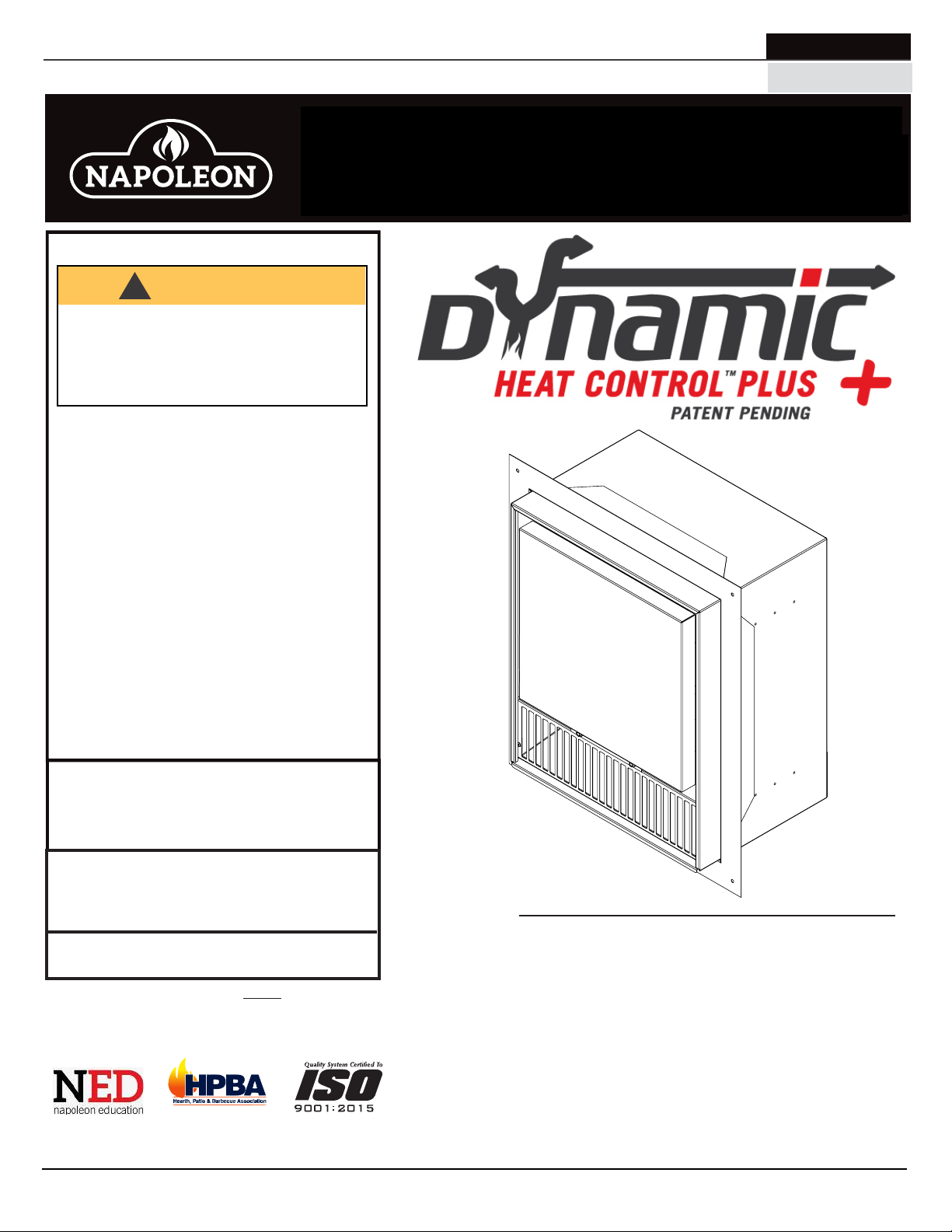
Napoleon DYNAMIC HEAT CONTROL PLUS, DHCP-BK, DHCP-HK, DHCP-EK Installation And Operation Manual
Page 1
NATURAL GAS MODELS:
DHCP-BK / DHCP-EK / DHCP-HK
ADD PRODUCT CODE HERE (TRADE GOTHIC LT STD FONT)
ENGLISH
PROPANE GAS MODELS:
SAFETY INFORMATION
!
WARNING
FIRE OR EXPLOSION HAZARD
Failure to follow safety warnings exactly
could result in serious injury, death, or
property damage.
- Do not store or use gasoline or other
fl ammable vapors and liquids in the vicinity of
this or any other appliance.
- WHAT TO DO IF YOU SMELL GAS:
• Do not try to light any appliance.
• Do not touch any electrical switch; do not
use any phone in your building.
• Immediately call your gas supplier from a
neighbour’s phone. Follow the gas
supplier’s instructions.
• If you cannot reach your gas supplier, call
the fi re department.
FRENCH
PG. 37
INSTALLATION AND
ADD MANUAL TITLE
OPERATION MANUAL
Product Name / Code
(MUST use title from Price Book)
ADD ____ ILLUSTRATED
ADD PRODUCT IMAGE
- Installation and service must be
performed by a qualifi ed installer, service
agency, or the supplier.
This appliance may be installed in an aftermarket,
permanently located, manufactured home (USA
only) or mobile home, where not prohibited by
local codes.
This appliance is only for use with the type of gas
Leave this manual with the appliance.
indicated on the rating plate. This appliance is
not convertible for use with other gases, unless
Retain this manual for future reference.
a certifi ed kit is used.
ENSURE TO ORDER CORRECT KITS.
SEE INSIDE FOR DETAILS.
Leave this manual with the appliance
These installation instructions MUST be used in
conjunction with the Vector™, Luxuria™, and
Retain this manual for future reference
Dynamic Heat Control™ installation manuals.
INSTALLER:
CONSUMER:
INSTALLER:
CONSUMER:
Wolf Steel Ltd., 24 Napoleon Rd., Barrie, ON, L4M 0G8 Canada / 103 Miller Drive, Crittenden, Kentucky, USA, 41030
Phone 1 (866) 820-8686 • www.napoleon.com • hearth@napoleon.com
CSA 2.22 AND ANSI Z21.50 FOR VENTED DECORATIVE GAS APPLIANCES
CSA /
INTERTEK
LOGO
DHCP-BK &
DHCP-EK Illustrated
FOR INDOOR USE ONLY
CERTIFIED TO THE CANADIAN AND AMERICAN NATIONAL STANDARDS:
FOR USE WITH VECTOR™
(with DHC™ installed)
& LUXURIA™ MODELS ONLY
IF INSTALLATION + OPERATION, ADD SERIAL
LV38N/P-1 / LV38N/P2-1 / LV50N/P-2 / LV50N/P2-2 /
IF SEPARATE MANUALS, ADD “PLACE
LVX38N/P / LVX38N/P2 / LVX50N/P / LVX50N/P2 /
BARCODE LABEL ON THE OWNER’S MANUAL”
NUMBER LABEL HERE
LV62N/P / LV62N/P2 / LV74N / LV74N2
LVX62N/P / LVX62N/P2 / LVX74N / LVX74N2
$10.00
W415-1789 / C / 01.29.19
Page 2
EN
table of contents
1.0 installation planning 3
1.1 introduction 3
1.2 installation options 3
1.3 DHC™ Plus kit overview 4
1.3.1 DHCP-BK 4
1.5.1 DHCP-EK 5
1.3.2 DHCP-HK 5
1.4 sound considerations 5
1.5 venting & ducting 5
1.6 placement in enclosure 6
1.7 dimensions 7
1.7.1 DHCP-BK & DHCP-EK 7
1.7.2 DHCP-BK & DHCP-HK 7
2.0 minimum ducting requirements 8
2.1 DHC™ Plus duct outlet 8
3.0 exterior & remote exterior
pre-installation 9
4.0 exterior installation 10
4.1 exterior installation overview 10
4.2 minimum framing requirements 11
4.3 completed installation checklist 13
5.0 remote exterior installation 14
5.1 remote exterior installation overview 14
5.2 minimum framing requirements 15
5.3 ducting installation 15
5.4 completed installation checklist 16
6.0 mounting options 17
6.1 flush 17
6.2 protruding 18
6.3 surface 19
7.0 remote inline pre-installation 20
8.0 remote inline installation 21
8.1 remote inline installation overview 21
8.2 minimum framing requirements 22
8.3 ducting installation 24
8.4 completed installation checklist 25
9.0 electrical information 26
9.1 wiring to SIT control board &
remote control 26
9.1.1 wiring diagram 28
9.2 wiring to wall switch & remote
control (in series) 28
9.2.1 wiring diagram 28
9.3 wiring to wall switch only 29
9.3.1 wiring diagram 29
9.4 blower specifications 29
10.0 operation 30
10.1 on/off switch 30
10.2 using remote control 30
11.0 replacement parts 31
11.1 DHCP-BK overview 32
11.2 DHCP-EK overview 33
11.3 DHCP-HK overview 34
12.0 notes 35
2
note:
The information throughout this manual is believed to be correct at the time of printing. Wolf Steel Ltd. reserves
the right to change or modify any information within this manual at any time without notice. Changes, other than
editorial, are denoted by a vertical line in the margin.
!
WARNING:
known to the State of California to cause cancer, and chemicals including toluene, which are
known to the State of California to cause birth defects or other reproductive harm.
For more information, go to www.P65Warnings.ca.gov.
W415-1789 / C / 01.29.19
This product can expose you to chemicals including chromium, which are
Page 3
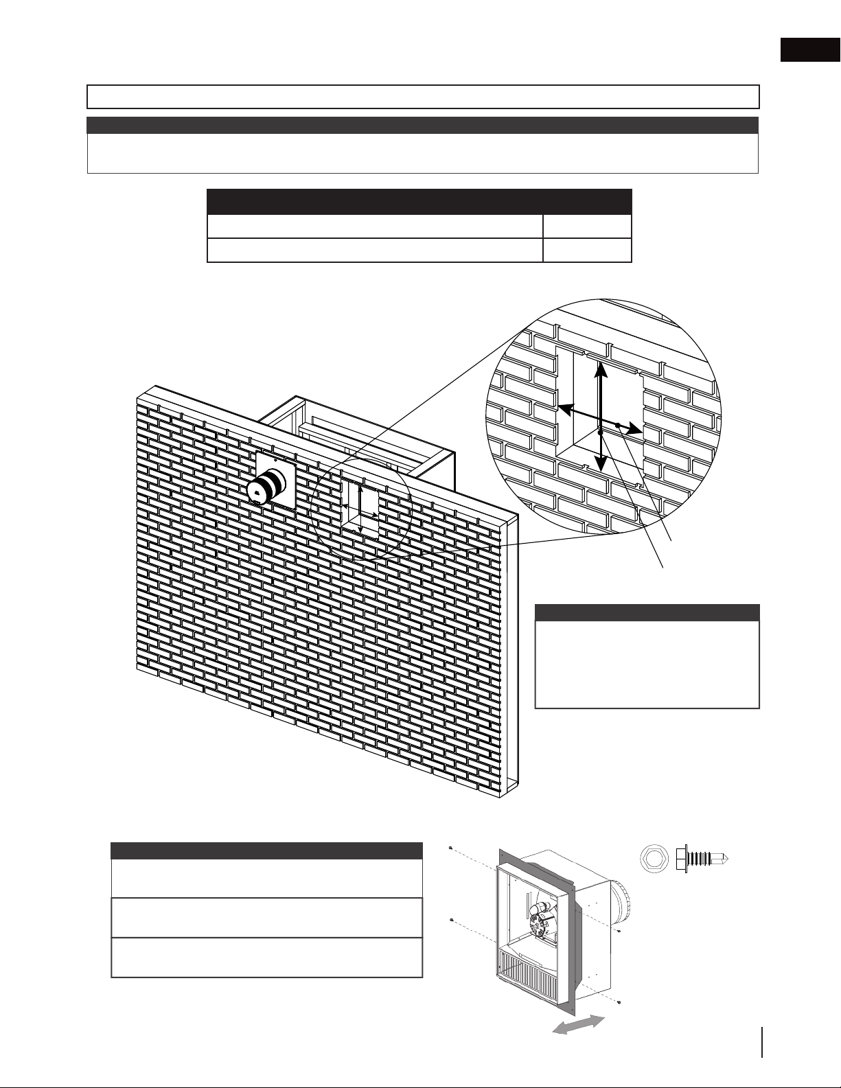
1.0 installation planning
!
WARNING
Dynamic Heat Control™ Plus (DHC™ Plus) CANNOT be installed without Dynamic Heat Control™.
DHC™ Plus is ONLY compatible with Dynamic Heat Control™ Installation Option #2 (front opening) or
Installation Option #3 (rear opening).
DHC™ Plus MUST be installed with an air outlet opening or it will become a potential fire hazard.
• Installation must conform to local codes or, in the absence of local codes, the National Gas and Propane
Installation Code CSA B149.1 in Canada, or the National Fuel Gas Code ANSI Z223.1 / NFPA 54 in the United
States.
• An appliance may use only one DHC™ Plus blower kit.
• We recommend installing DHC™ Plus during installation of the appliance BEFORE appliance venting and gas
are installed.
• Installation MUST be performed by a qualified installer who has completed the Dynamic Heat Control™ System
Certification course via Napoleon’s online education portal NEducation.
• Ensure the appliance is completely cool before starting installation.
• To avoid danger of suffocation, keep the packaging bag away from babies and children. Do not use in cribs,
beds, carriages, or play pens. This bag is not a toy. Knot before throwing away.
1.1 introduction
Dynamic Heat Control™ Plus (DHC™ Plus) is a system for managing the heat produced by the appliance at
and around the appliance. The purpose of DHC™ Plus is to move heat away from the appliance and to primarily
distribute some or all of it to the exterior. Where duct lengths are greater than 5 feet or when passing through
uninsulated spaces such as an attic, it is recommended that the duct be insulated.
EN
Whilst it is practically possible to use DHC™ Plus to move heat to another location within the home,
please consider the following points carefully during the planning phase:
• The sound of the DHC™ Plus blower is similar to a bathroom fan (see “sound considerations” section).
• The DHC™ Plus system should not be used in small enclosed rooms with low ceilings, such as a small
bathroom, as the room will be quickly pressurized and the heat transfer from the fireplace will be reduced /
eliminated.
• The DHC™ Plus moves almost all the useable
heat. If the room is small in volume, it can quickly
become very warm. You may move unwanted
heat from one room to another, which may not
satisfy the customer. Therefore, carefully consider
the amount of heat and the size of the room
where it is being transferred to before beginning
installation.
• Where the DHC™ Plus system is used to transfer heat to another room, it is recommended to install a local
on/off switch so that the heat transfer can be disabled from the remote location if desired. The DHC™ Plus
system does not include a remote room thermostat.
1.2 installation options
There are three installation options available for DHC™ Plus, each with its own advantages:
Exterior Installation
DHC™ Plus is installed on the exterior wall of the appliance enclosure. It does not require venting, ducting, or a
bulkhead, and is therefore the simplest installation option. However, careful consideration should be made for the
sound of the DHC™ Plus blower. See “sound considerations” and “exterior installation” sections for details.
Remote Exterior Installation
DHC™ Plus is installed remotely from the appliance enclosure. Though it requires venting and a bulkhead, the
increased distance from the blower ensures sounds from air flow will be significantly less apparent. See “sound
considerations” and “remote exterior installation” sections for details.
Remote Inline Installation
DHC™ Plus is installed inline anywhere between the appliance enclosure and the hot air exhaust assembly.
Similarly to remote exterior installations, this installation requires venting and a bulkhead, with the addition of
ducting. This installation offers the most opportunity for unique configurations, including through multiples rooms
or floor levels. See “remote inline installation” section for details.
W415-1789 / C / 01.29.19
3
Page 4
EN
Hex
Hex
Hex
29/64”
1/8”
1-1/2”
Quadrex Drive
0.141”
Hex
installation planning
The table below lists kit requirements for each installation option. Please read it carefully.
Installation Type DHCP-BK DHCP-EK DHCP-HK
Exterior
Remote Exterior
Remote Inline
N/A
N/A
N/A
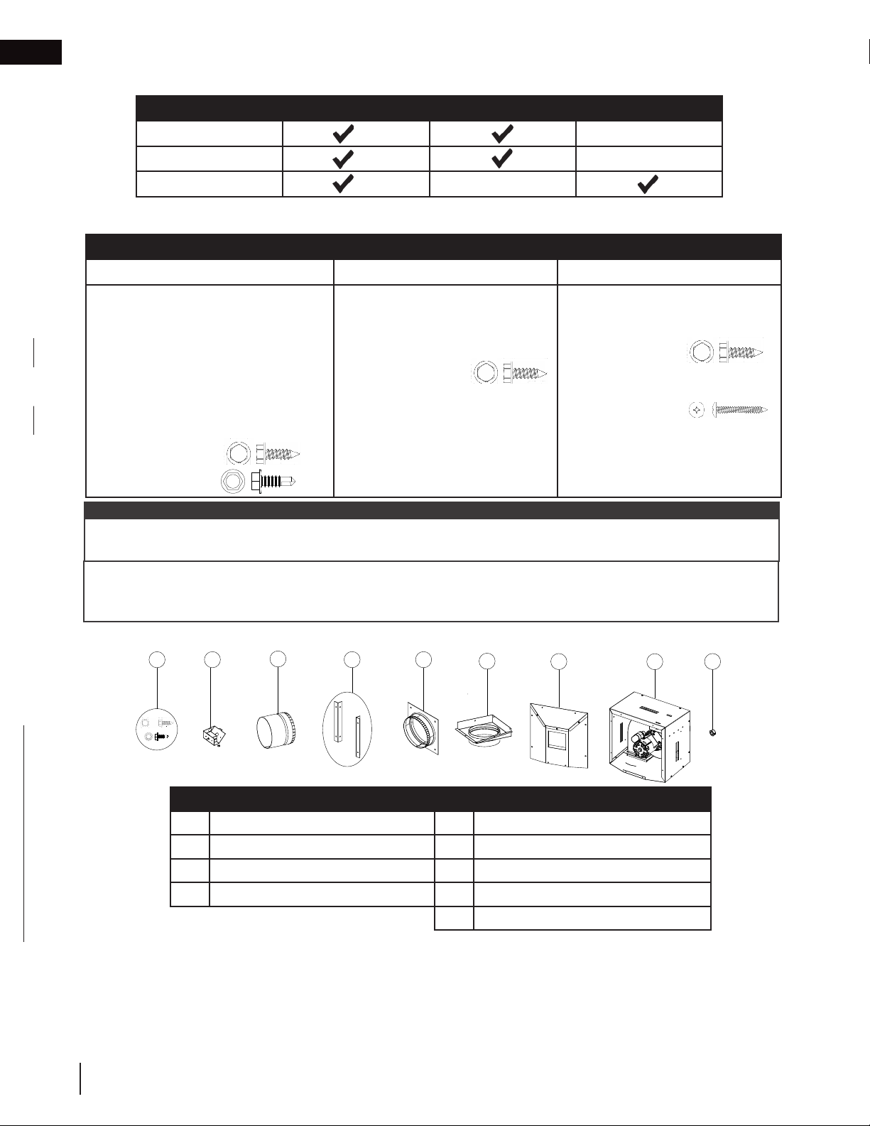
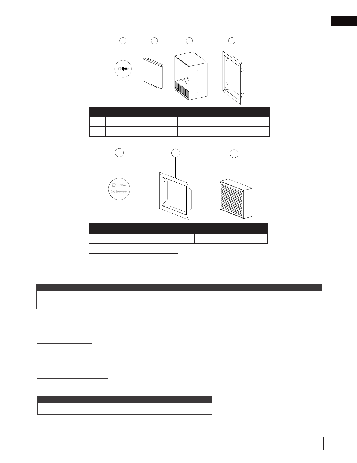
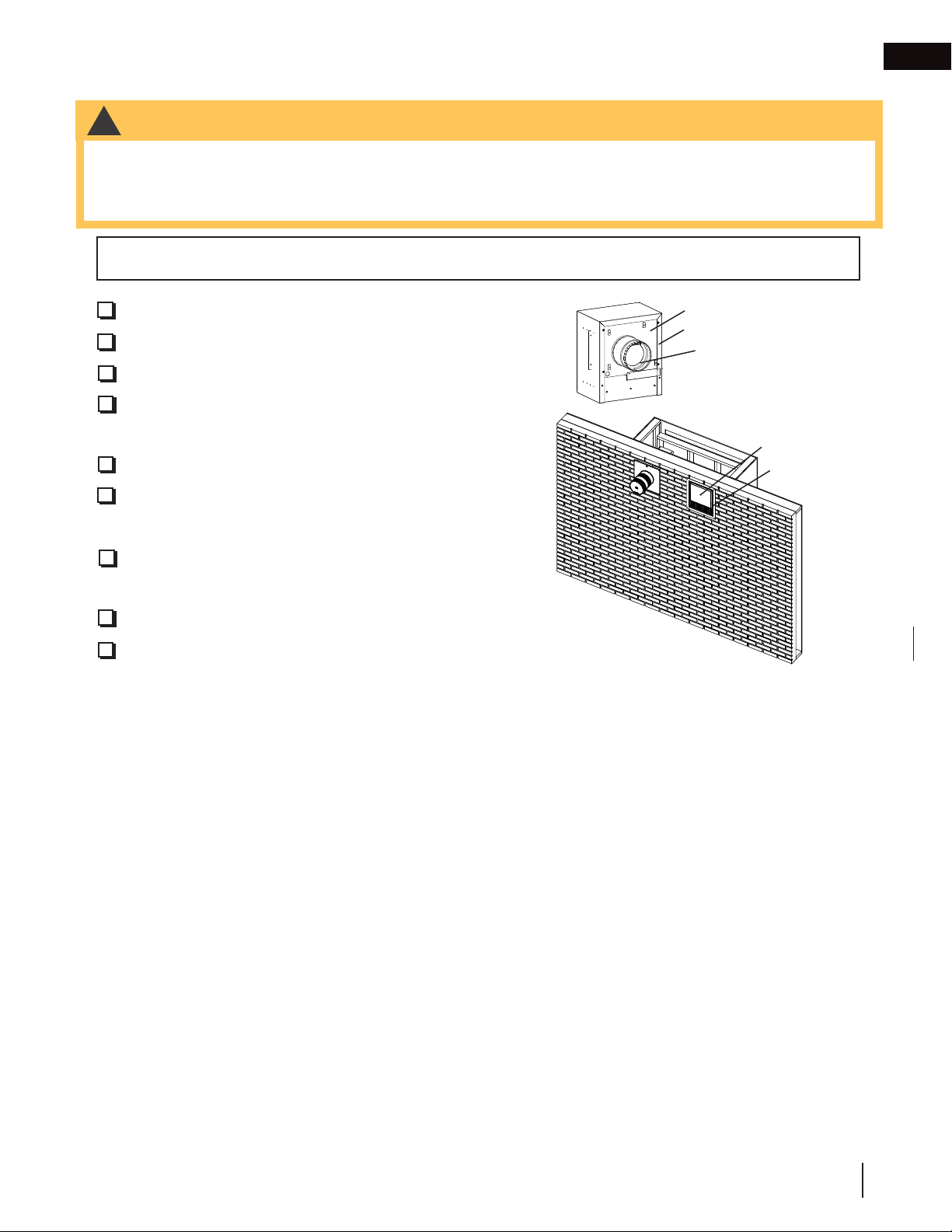
1.3 DHC™ Plus kit overview
Included in each kit:
DHCP-BK DHCP-EK DHCP-HK
1 x blower housing assembly
1x inline cover assembly
1 x air damper assembly
1 x on/off switch / housing
1 x collar connector assembly
1 x collar plate assembly
2 x mounting bracket
1 x bushing
13 x #9x1/2” screws
7 x #8x1/2” screws
note:
These complete kits always comprise of up to 2 boxes. Please read carefully and ensure to order correct application kits for your unique installation.
1 x exterior housing assembly
1 x wall flashing
1 x decorative cover
12 x #9x1/2” screws
1 x hot air exhaust assembly
1 x wall flashing
4 x #9x1/2” screws
2 x #10x1-1/2” screws
#10 Thread, RH
Though not supplied, armoured cable is required for the wiring of the DHC™ Plus (see “electrical information”
section for more information). Therefore, please ensure you have enough armoured cable on-hand to complete
your unique installation.
1.3.1 DHCP-BK
1
#9-14 Thread, RH
2
Ref. Description Ref. Description
1 Hardware kit 5 Collar plate assembly
2 On/off switch (with housing and nut) 6 Collar connector assembly
3 Air damper assembly 7 Inline cover assembly
4 Mounting brackets (x2) 8 Blower housing assembly
3
4 5
6
7
8
9
9 Bushing
4
W415-1789 / C / 01.29.19
Page 5
Hex
1.5.1 DHCP-EK
1.3.2 DHCP-HK
installation planning
1 3 4
Ref. Description Ref. Description
1 Hardware kit 3 Exterior housing assembly
2 Decorative cover 4 Wall flashing
1
#9-14 Thread, RH
29/64”
1/8”
1-1/2”
#10 Thread, RH
Quadrex Drive
2
2
3
EN
Ref. Description Ref. Description
1 Hardware kit 3 Hot air exhaust assembly
2 Wall flashing
1.4 sound considerations
The DHC™ Plus system uses a high performance fan to move unwanted heat outside. Similar to a bathroom fan
or stove range hood, the use of a fan to move air results in sound.
note:
Consider blower kit location carefully as the air flow sound from the blower is more apparent the closer it is to the
appliance and customer. This is particularly important if using the fan to transfer heat inside a home.
1.5 venting & ducting
Depending on the installation type, DHC™ Plus requires the use of ducting that is not supplied:
Exterior Installation
• N/A
Remote Exterior Installation
• 6” steel rigid venting between appliance enclosure and DHC™ Plus blower kit
Remote Inline Installation
• 6” steel ducting between appliance enclosure and DHC™ Plus blower kit
• 6” steel rigid venting between DHC™ Plus blower kit and hot air exhaust assembly
note:
Always check local codes before installing the DHC™ Plus system.
W415-1789 / C / 01.29.19
5
Page 6
EN
installation planning
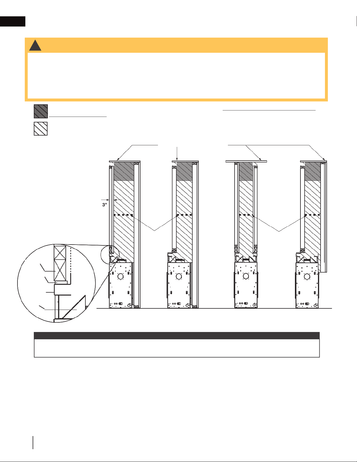
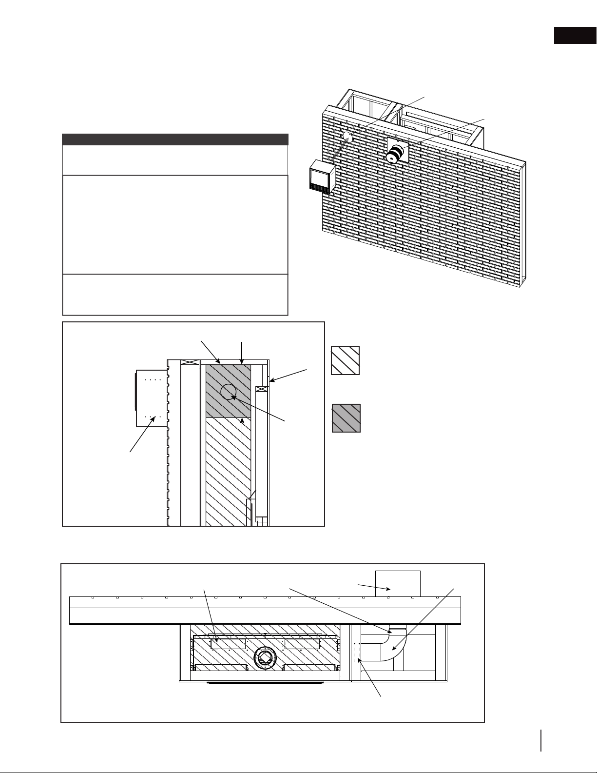
1.6 placement in enclosure
WARNING
!
• Do NOT cover or place any items in the Dynamic Heat Control™ air outlet. Failure to comply with these
instructions could create a fire hazard.
• Ensure a
vent system or the DHC™ Plus system.
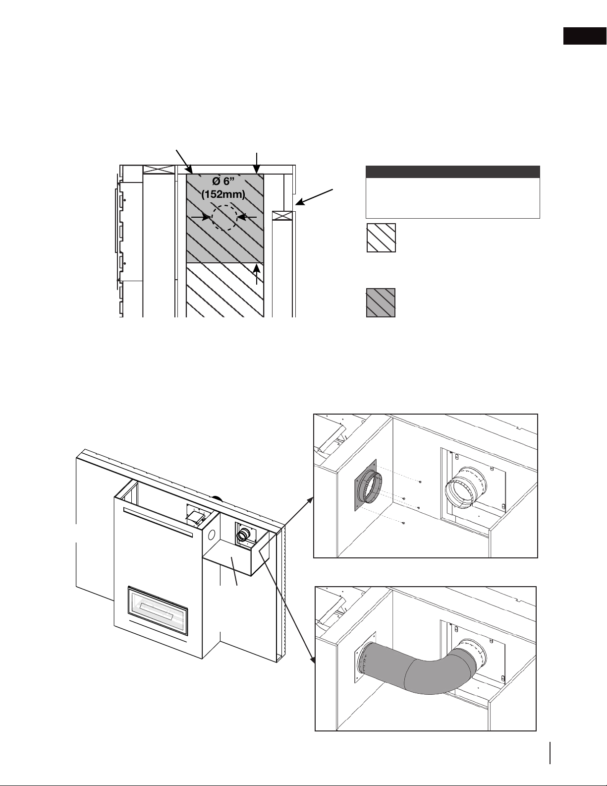
The DHC™ Plus system draws air from the appliance enclosure and should be mounted in the
enclosure above the appliance. NEVER make a direct connection to the appliance itself.
ir flow within the air passage is not restricted in any way with the exception of an approved appliance
Recommended DHC™ Plus collar plate assembly installation zone - within the top 12” (30.5cm) of the
appliance enclosure.
No materials of any type permitted in this area with the exception of an approved appliance vent system or
the DHC™ Plus system.
enclosure top and/or ceiling
*
Stud
Stand-Off
Upper
Frame
Deflector
Dynamic Heat
Control™ air
outlet opening
* *
3”
Minimum
33” (83cm)
above
appliance
**
Single-Sided
Single-Sided
(Recessed)***
See-thru
*
Minimum
33” (83cm)
above
appliance
*
**
Single-Sided
(Exterior Recess)
important:
** DHC™ Plus collar plate assembly must be installed above the appliance vent shield (not illustrated) (minimum
33” (83cm) from the top of the appliance).
*** Restrictions also apply to see-thru when one or more recess is used. See your appliance manual for details.
Air flow in the hatched areas must not be restricted in any way with the exception of an approved appliance vent
system or the DHC™ Plus system. No other items are allowed in this area.
See your appliance manual for more information about clearance to combusible materials. No combustible materials allowed in the hatched areas or the space between studs (i.e. no wiring, conduits, electrical bores, combustible framing members, etc.).
6
W415-1789 / C / 01.29.19
Page 7

1.7 dimensions
REV.
025435
C
B
D
8
REV.
DHCP-BK
C
B
D
8
REV.
DHCP-HK
C
B
D
8
1.7.1 DHCP-BK & DHCP-EK
FOR EXTERIOR & REMOTE EXTERIOR INSTALLATIONS ONLY
installation planning
EN
front view right side view
15/16"
25mm
16 3/4"
425mm
18 1/2"
469mm
14 1/16"
357mm
16"
406mm
1.7.2 DHCP-BK & DHCP-HK
FOR REMOTE INLINE INSTALLATIONS ONLY
DHCP-BK
front view right side view
3 3/16"
81mm
6"
152mm
1/2"
13mm
13 3/16"
335mm
14 3/16"
360mm
22mm
7/8"
19 15/16"
507mm
1 1/2"
38mm
ADJUSTABLE FROM FLUSH TO SURFACE MOUNT IN
1 1/2" INCREMENTS. (SHOWN 1 1/2" PROUD OF
FINISHING IN THIS DIAGRAM)
3 1/2"
90mm
11 11/16"
297mm
1 1/2"
[40mm]
168mm
6 3/16"
157mm
6 5/8"
top view
8 1/4"
209mm
6"
152mm
9 7/8"
251mm
1 13/16"
45mm
top view
8"
199mm
6"
152mm
9 5/16"
236mm
1 13/16"
46mm
14 1/4"
362mm
4"
102mm
6"
152mm
3 7/8"
98mm
DHCP-HK
front view right side view
14 1/2"
368mm
3/4"
19mm
12 11/16"
322mm
16"
406mm
279mm
11"
13/16"
21mm
5 13/16"
148mm
1 1/2"
38mm
5 9/16"
142mm
7 3/16"
183mm
top view
6"
152mm
W415-1789 / C / 01.29.19
1 13/16"
46mm
102mm
4"
7
Page 8
EN
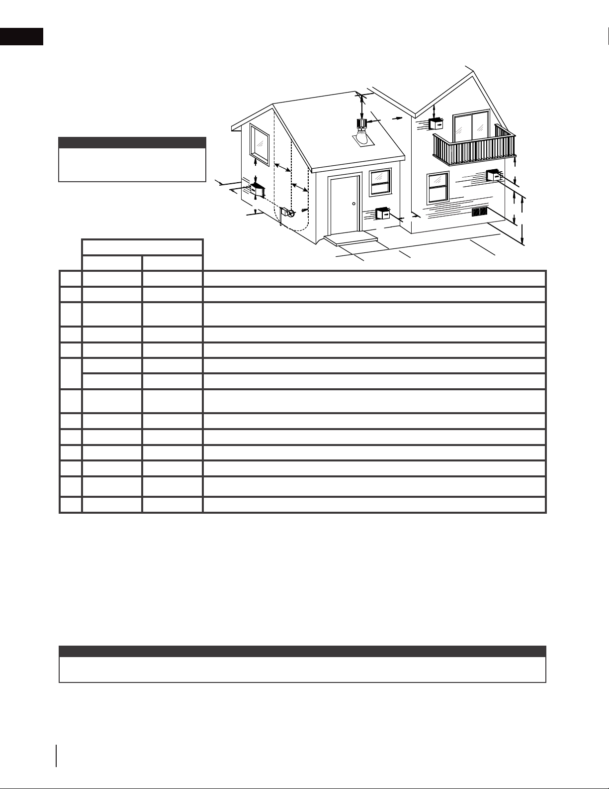
2.0 minimum ducting requirements
2.1 DHC™ Plus duct outlet
note:
Wall terminals are for illustration
purposes only. Size and shapes may
vary.
B
G
C
D
M
C
D
L
E
G
A
H
INSTALLATIONS
CANADA U.S.A.
12” (30.5cm) 12” (30.5cm) Clearance above grade, veranda porch, deck or balcony.
A
12” (30.5cm)* 12” (30.5cm)* Clearance to windows.
B
C
D
E
F
G
H
I
J
K
12”
(30.5cm)**
12” (30.5cm)** 12” (30.5cm)** Clearance to unventilated soffit.
0” (0mm) 0” (0mm) Clearance to an outside corner wall.
0” (0mm) 0” (0mm)
2” (51mm) 2” (51mm) Clearance to an inside combustible corner wall or protruding combustible obstructions (vent chase, etc.).
3’(0.9m) 3’(0.9m)****
3’ (0.9m) 3’ (0.9m)**** Clearance to a service regulator vent outlet.
12” (30.5cm) 9” (229mm) Clearance to a non-mechanical air supply inlet to the building or a combustion air inlet to any other appliance.
6’ (1.8m) 3’ (0.9m) † Clearance to a mechanical air supply inlet.
7’ (2.1m) ‡ 7’ (2.1m) **** Clearance above a paved sidewalk or paved driveway located on public property.
12”
(30.5cm)**
Vertical clearance to ventilated soffits located above the terminal within a horizontal distance of 2’ (0.6m)
from the center line of the terminal.
Clearance to an inside non-combustible corner wall or protruding non-combustible obstructions (chimney, etc.).
Clearance to each side of the center line extended above the meter / regulator assembly to a maximum
vertical distance of 15’ (4.6m).
F
I
J
K
12” (30.5cm)**** 12” (30.5cm)**** Clearance under a veranda, porch or deck.
L
1’ (0.3m)†* 1’ (0.3m) †* Clearance from an adjacent wall including neighbouring buildings.
M
* Recommended to prevent condensation on windows and thermal breakage
** It is recommended to maximize the distance to vinyl clad soffits.
**** This is a recommended distance. For additional requirements, check local codes.
† 3 feet above if within 10 feet horizontally.
‡ A vent shall not terminate where it may cause hazardous frost or ice accumulations on adjacent property surfaces.
†† Permitted only if the veranda, porch, or deck is fully open on a minimum of two sides beneath the floor.
†* Recommended for service. For additional requirements, check local codes.
note:
Clearances are to be in accordance with local installation codes and the requirements of the gas supplier. In their absence, clearances are to
be as listed above and are based on national codes.
8
W415-1789 / C / 01.29.19
Page 9
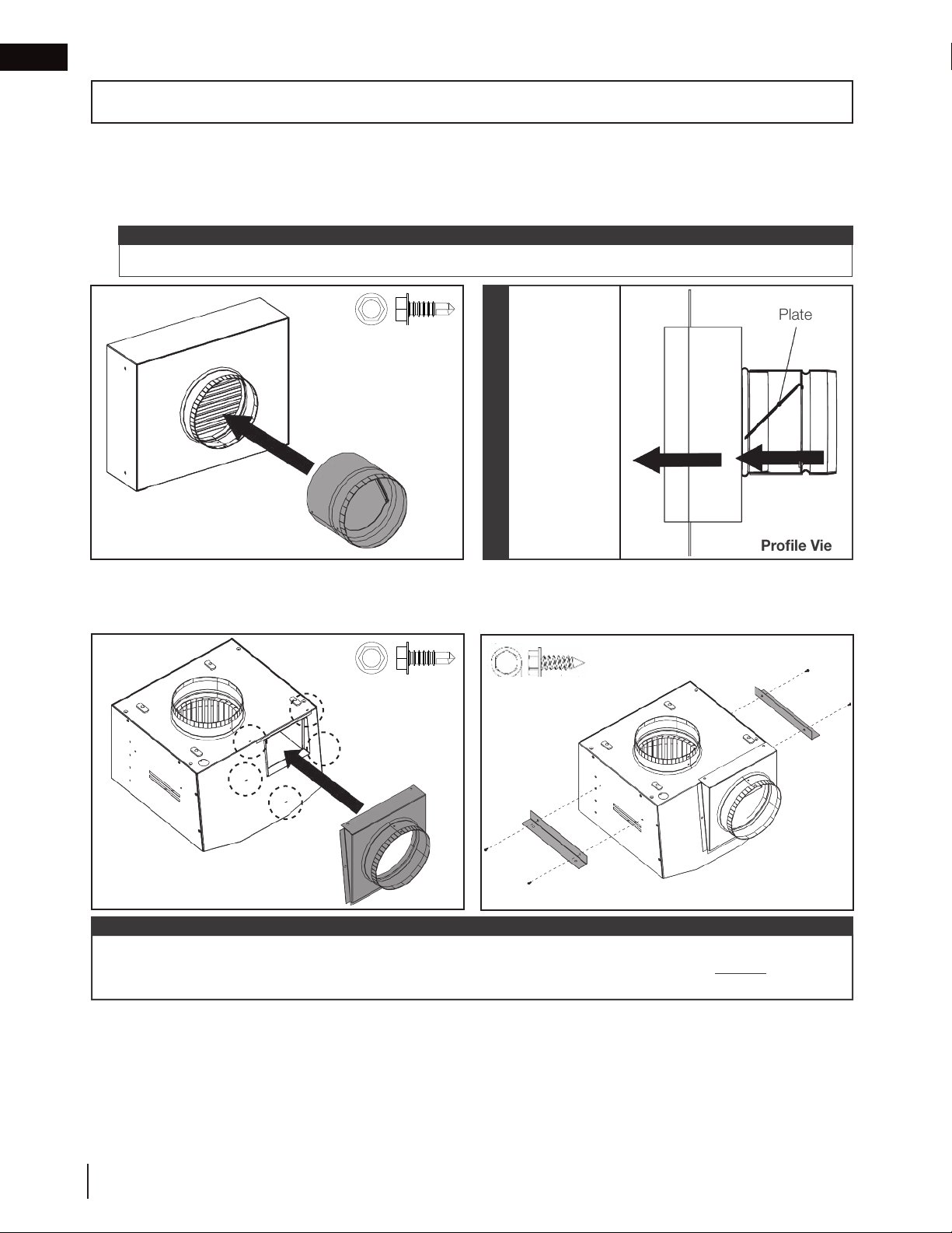
3.0 exterior & remote exterior pre-installation
Hex
FOR EXTERIOR AND REMOTE EXTERIOR INSTALLATIONS ONLY
For exterior and remote exterior installations, you must follow the instructions below before beginning installation.
For inline installations, see “remote inline pre-installation” section.
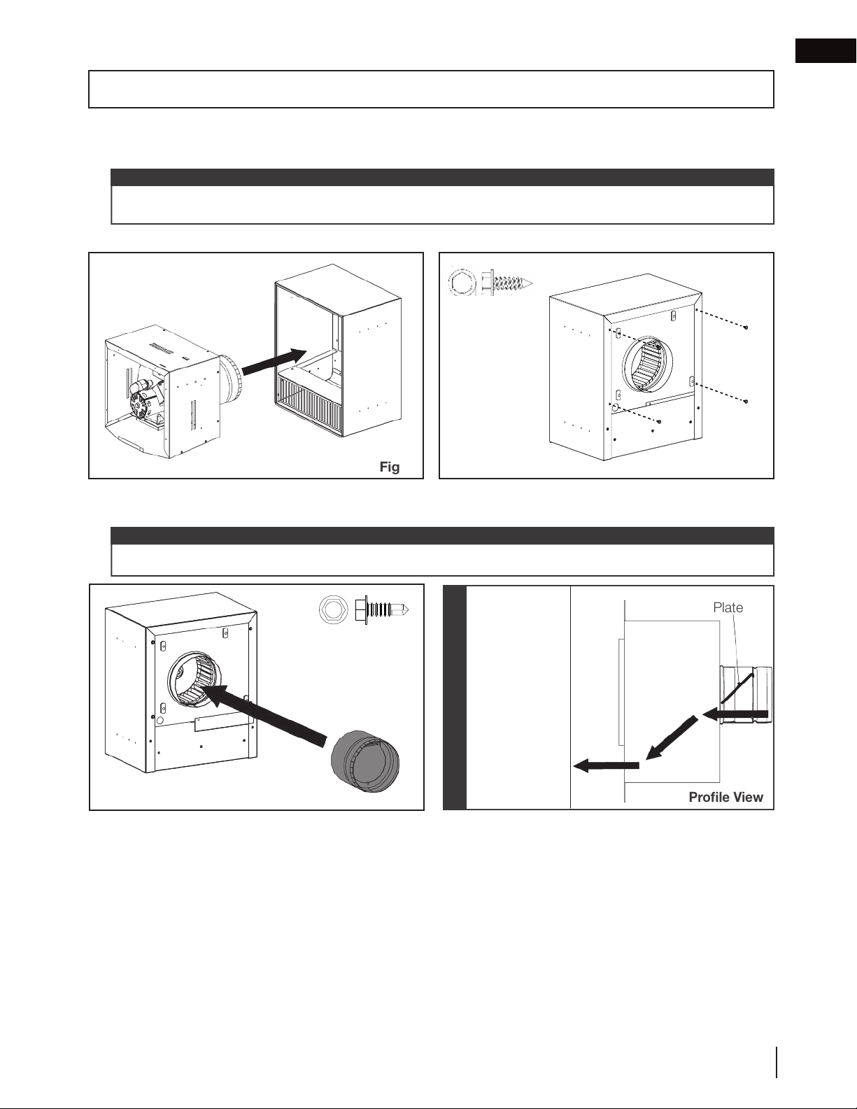
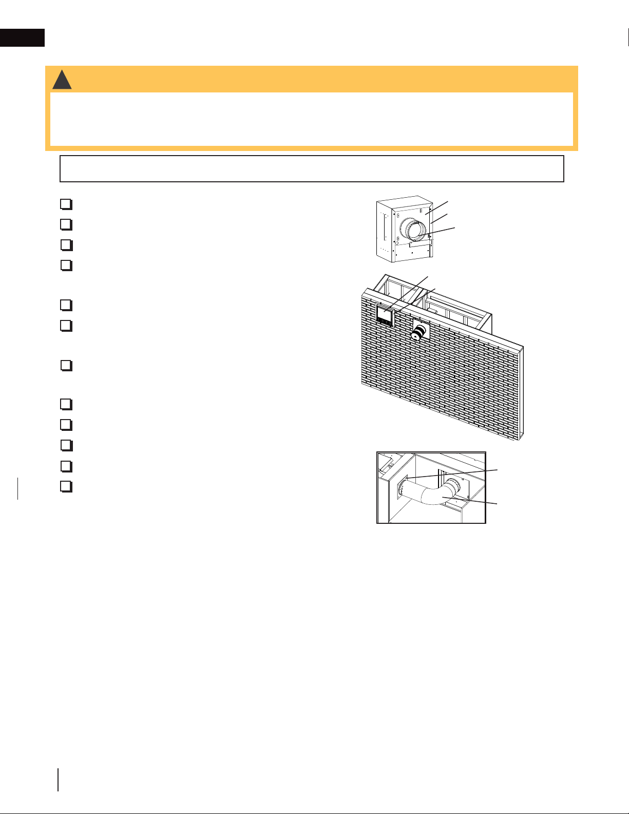
1. Insert the blower housing assembly into the exterior housing assembly. Ensure correct orientation (Fig. 1).
note:
We recommend installing the inline cover assembly and decorative cover last, after all electrical wiring is
complete. See “electrical information” section for installation instructions.
2. Secure the blower housing assembly to the exterior housing assembly using 4 screws (supplied) (Fig. 2).
x 4
EN
Fig. 1
3. Install the air damper assembly onto the collar and secure using self-drilling screws (supplied) (Fig. 3). Rotate
so that the damper closes shut when the blower is not running.
note:
The air damper assembly must be closed when the blower is not running for the system to function correctly.
The plate of
the air damper
x 3
Fig. 3
assembly must
open from the
bottom. Take
care to install
in the correct
orientation so it
IMPORTANT
will open when
the blower operates. Always test
before finishing.
Fig. 2
Plate
Profile View
W415-1789 / C / 01.29.19
9
Page 10

EN
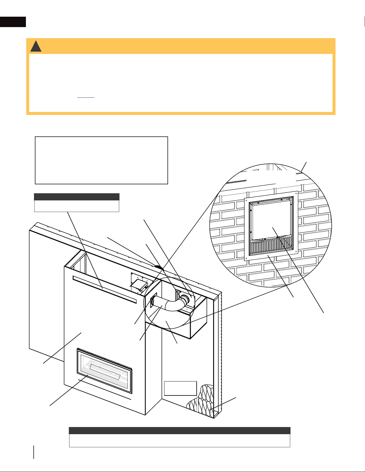
4.0 exterior installation
4.1 exterior installation overview
!
WARNING
• Minimum clearance to combustibles must be maintained or a serious fire hazard could result.
• DO NOT cover or place any items in the Dynamic Heat Control™ air outlet opening. Failure to comply with
these instructions will create a fire hazard.
DHC™ Plus CANNOT be mounted directly above or below the appliance vent terminal as this will
cause the system to fail. It MUST be mounted to the left or right of the appliance vent terminal.
• For optimal performance, we recommend installing DHC™ Plus within the top 12” (30.5cm) of the enclosure.
However, it MUST be installed above the appliance.
• The minimum height requirement above the appliance will vary depending on the appliance size. See “minimum
venting requirements” section of your appliance manual for details.
DHC™ Plus exterior installation is the simplest installation option. It is installed on the exterior wall of the appliance enclosure.
Required:
• DHCP-BK
• DHCP-EK
Blower
Housing
Assembly
Air
Damper
Assembly
note:
MUST have air outlet opening.
Wall
Flashing
Decorative
Cover
Appliance
Vent Terminal
(if applicable)
View of Opposite
Exterior Wall
Exterior
Exterior
Housing
Assembly
10
Enclosure
Appliance
note:
Diagram is for illustrative purposes only. Installation must comply with all local codes.
W415-1789 / C / 01.29.19
GLASS GUARD
LVX38 illustrated
Interior
Maintain
distance to
combustibles.
Insulation
Page 11
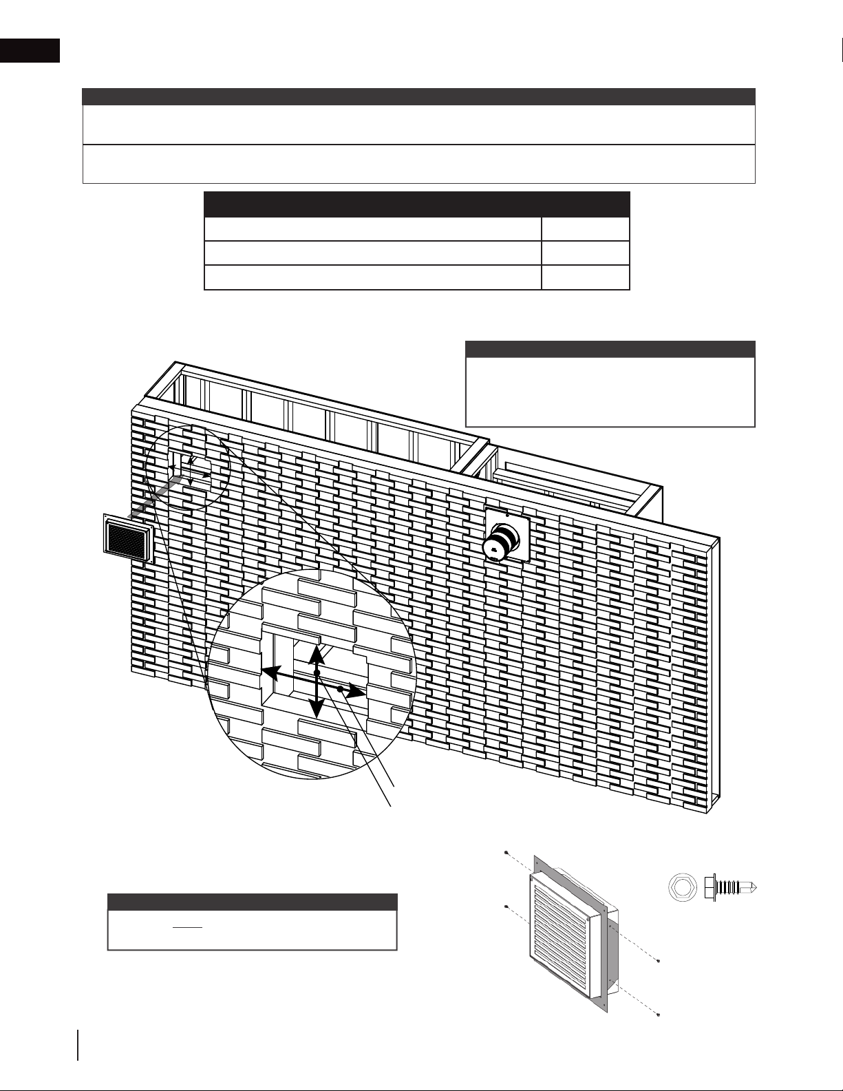
exterior installation
4.2 minimum framing requirements
APPLICABLE FOR EXTERIOR AND REMOTE EXTERIOR INSTALLATIONS
note:
For optimal performance, we recommend installing DHC™ Plus within the top 12” (30.5cm) of the enclosure.
The DHC™ Plus must be mounted above the appliance.
Minimum Clearance to Combustibles Clearance
DHCP-EK 0”
Vent pipe, collars, firestops, etc. 1” (25mm)
1. Determine the desired location of the exterior housing assembly on the exterior wall, and then frame a 14 1/2”
(36.8cm) wide by 17 1/4” (44cm) high opening (Fig. 1).
Interior
Interior
EN
14 1/2” (36.8cm)
17 1/4” (44cm)
note:
It may be necessary to shim the
blower housing in the rough opening
to provide a secure fit. If the blower
Exterior
Exterior
Exterior Installation Illustrated
2. Determine the desired amount of protrusion from the finished exterior wall, and then fasten the wall flashing
using 4 screws (supplied) (Fig. 2). See “mounting options” section for details.
note:
The exterior housing assembly MUST be pre-drilled
with a 1/8” drill bit before installing the wall flashing.
To avoid scratches, we recommend sliding the wall
flashing on from the back.
is not secured properly, excessive
noise and vibration may result.
Fig. 1
x 4
If surface-mounting your DHC™ Plus, this step is
not required (see “mounting options” section).
Fig. 2
W415-1789 / C / 01.29.19
11
Page 12
EN
exterior installation
3. Attach the exterior housing assembly to the exterior wall by securing the wall flashing using the appropriate
fasteners (not supplied) (Fig. 3).
4. Apply silicone to the joint after installation, and caulk or seal the wall flashing appropriately for the finish material (Fig. 4).
SILICONE
Interior
CAULK
Fig. 4
Exterior
Exterior Installation Illustrated
5. We recommend installing the inline cover assembly and decorative cover last, after all electrical wiring is complete. See “electrical information” section for installation instructions.
Fig. 3
12
W415-1789 / C / 01.29.19
Page 13
exterior installation
4.3 completed installation checklist
!
WARNING
• Ensure all items are checked for your respective installation or a serious fire hazard could result.
• Completed installations must conform to local codes or, in the absence of local codes, the National Gas and
Propane Installation Code CSA B149.1 in Canada, or the National Fuel Gas Code ANSI Z223.1 / NFPA 54 in the
United States.
Installer, please tick all boxes for this installation or it IS NOT considered complete.
EN
1. DHCP-BK installed into DHCP-EK.
2. Air damper assembly installed and checked.
3. Rough opening framed into exterior wall.
4. Wall flashing installed and sealed appropriately for finish
material.
5. DHCP-EK attached to exterior wall.
6. Inline cover assembly installed (see “electrical information” section).
7. Decorative cover installed and system operation checked
with appliance (see “electrical information” section).
8. Wiring completed (see “electrical information” section).
9. On/off switch adjusted to fully “on” position.
DHCP-BK
DHCP-EK
Air Damper Assembly
Decorative Cover
Wall Flashing
Interior
Exterior
W415-1789 / C / 01.29.19
13
Page 14
EN
5.0 remote exterior installation
5.1 remote exterior installation overview
!
WARNING
• Minimum clearance to combustibles must be maintained or a serious fire hazard could result.
• DO NOT cover or place any items in the Dynamic Heat Control™ air outlet opening. Failure to comply with
these instructions will create a fire hazard.
DHC™ Plus CANNOT be mounted directly above or below the appliance vent terminal as this will
cause the system to fail. It MUST be mounted to the left or right of the appliance vent terminal.
• For optimal performance, we recommend installing DHC™ Plus within the top 12” (30.5cm) of the enclosure.
However, it MUST be installed above the appliance.
• The minimum height requirement above the appliance will vary depending on the appliance size. See “minimum
venting requirements” section of your appliance manual for details.
DHC™ Plus remote exterior installation can be installed remotely from the appliance enclosure up to 60’ (18.2m)
away.
Required:
• DHCP-BK
• DHCP-EK
• Venting, 6” rigid steel (not supplied)
View of Opposite
Exterior Wall
Exterior Housing
Assembly
note:
MUST have air outlet opening.
Appliance Vent
Terminal (if
applicable)
Enclosure
GLASS GUARD
Blower
Housing
Assembly
Air
Damper
Assembly
Collar Plate
Assembly
6” Rigid Steel
Venting (not
supplied)
Inside View
of Bulkhead
(Some Framing and
Finishing Hidden
for Clarity)
Wall
Flashing
Decorative
Cover
Exterior
14
Appliance
note:
Diagram is for illustrative purposes only. Installation must comply with all local codes.
W415-1789 / C / 01.29.19
LVX 38 illustrated
Maintain
distance to
combustibles.
Interior
Insulation
Page 15
remote exterior installation
12”
5.2 minimum framing requirements
See “minimum framing requirements” in exterior installation section for details.
5.3 ducting installation
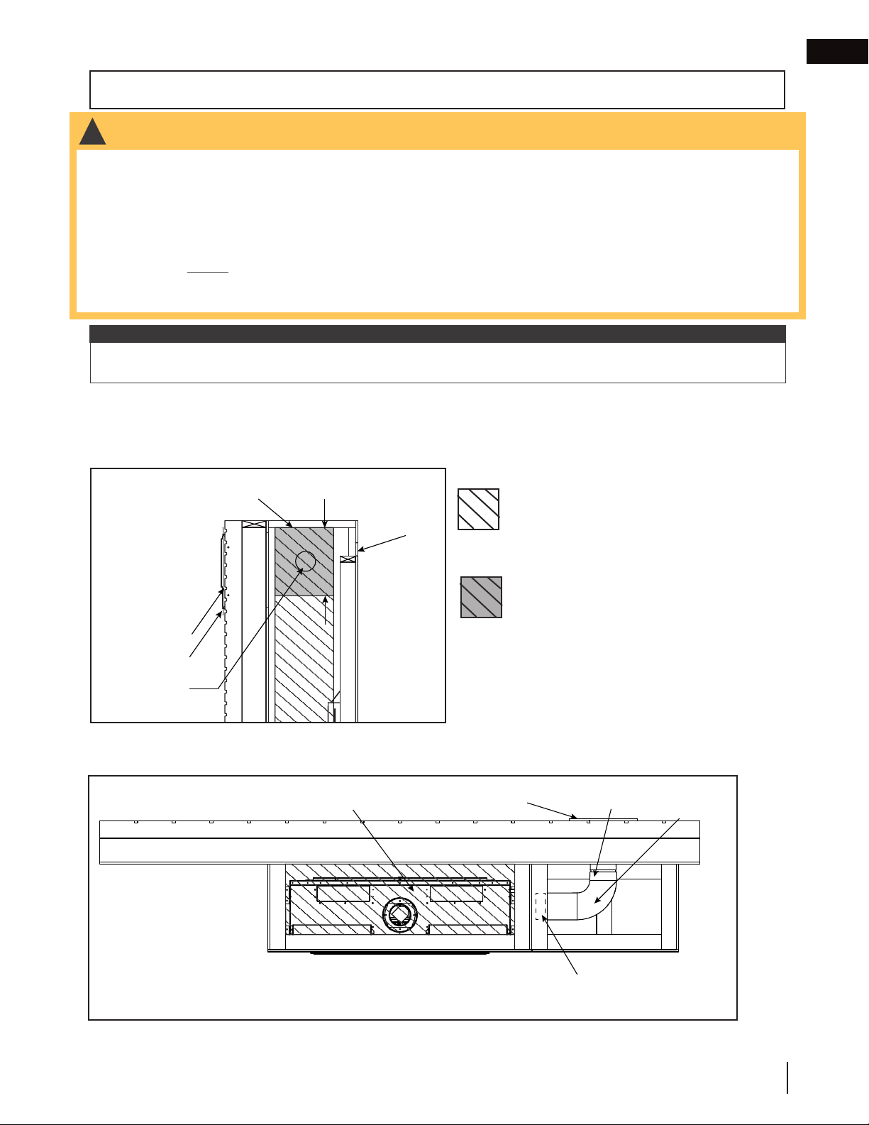
1. Determine the location for the 6” (152mm) collar plate assembly on the appliance enclosure, and then cut a
hole 6” (152mm) in diameter (Fig. 1).
EN
Top of Enclosure
(152mm)
Exterior
Ø 6”
(30.5cm)
Air Outlet
Opening
Interior
Fig. 1
note:
Ensure to create the Ø 6” (152mm)
hole within the top 12” (30.5cm) of the
enclosure (Fig. 1).
No materials of any type
permitted in this area with
the exception of an approved
appliance vent system or the
DHC™ Plus system.
Recommended DHC™ Plus
collar plate assembly installation
zone (12” [30.5cm]).
Left Side Profile View
2. Using appropriate fasteners (not supplied), secure the 6” (152mm) collar plate assembly over the hole inside
the bulkhead (Fig. 2).
3. Install 6” rigid steel venting (not supplied) from the appliance enclosure to the blower housing assembly (Fig.
3).
Interior
Exterior
GLASS GUARD
LVX 38 illustrated
Fig. 2
Inside View
of Bulkhead
(Some Framing
and Finishing
Hidden for Clarity)
Fig. 3
W415-1789 / C / 01.29.19
15
Page 16
EN
remote exterior installation
5.4 completed installation checklist
!
WARNING
• Ensure all items are checked for your respective installation or a serious fire hazard could result.
• Completed installations must conform to local codes or, in the absence of local codes, the National Gas and
Propane Installation Code CSA B149.1 in Canada, or the National Fuel Gas Code ANSI Z223.1 / NFPA 54 in the
United States.
Installer, please tick all boxes for this installation or it IS NOT considered complete.
1. DHCP-BK installed into DHCP-EK.
2. Air damper assembly installed and checked.
3. Rough opening framed into exterior wall.
4. Wall flashing installed and sealed appropriately for finish
material.
5. DHCP-EK attached to exterior wall.
6. Inline cover assembly installed (see “electrical information” section).
7. Decorative cover installed and system operation checked
with appliance (see “electrical information” section).
8. Ø 6” (152mm) hole cut into appliance enclosure.
9. Collar plate assembly secured.
10. 6” rigid steel venting (not supplied) installed.
11. Wiring completed (see “electrical information” section).
12. On/off switch adjusted to fully “on” position.
DHCP-BK
DHCP-EK
Air Damper Assembly
Decorative Cover
Wall Flashing
Interior
Exterior
6” Collar Plate
Assembly
6” Rigid Steel
Venting
(Not Supplied)
16
W415-1789 / C / 01.29.19
Page 17
6.0 mounting options
FOR EXTERIOR AND REMOTE EXTERIOR INSTALLATIONS ONLY
!
WARNING
• Minimum clearance to combustibles must be maintained or a serious fire hazard could result.
• DO NOT cover or place any items in the Dynamic Heat Control™ air outlet opening. Failure to comply with
these instructions will create a fire hazard.
DHC™ Plus CANNOT be mounted directly above or below the appliance vent terminal as this will
cause the system to fail. It MUST be mounted to the left or right of the appliance vent terminal.
• For optimal performance, we recommend installing DHC™ Plus within the top 12” (30.5cm) of the enclosure.
However, it MUST be installed above the appliance.
• The minimum height requirement above the appliance will vary depending on the appliance size. See “minimum
venting requirements” section of your appliance manual for details.
note:
Consider blower location carefully as the air flow sound from the blower is more apparent the closer it is to the
appliance. See “sound considerations” section for details.
6.1 flush
In this mounting option, the wall flashing and exterior housing assembly are flush with the finished exterior wall.
A
14 1/2” (36.8cm) by 17 1/4” (44cm) rectangular opening must be framed into the exterior wall (see “minimum
framing requirements” section for details).
EN
Top of
Enclosure
Exterior
Exterior Housing
Asssembly
Wall Flashing
Ø 6” (152mm)
Hole & Installed Collar
Plate Assembly
12”
(30.5cm)
Air Outlet
Opening
Interior
Left Side Profile View
(Remote Exterior Installation illustrated. Some components may not apply
to your unique installation.)
Exterior
Appliance
(LVX38 Illustrated)
No materials of any type permitted in this
area with the exception of an approved
appliance vent system or the DHC™ Plus
system.
Recommended DHC™ Plus collar plate
assembly installation zone (12” [30.5cm]).
Exterior Housing
Assembly
Air Damper
Assembly
6’ Rigid
Steel Venting
(not supplied)
Interior
Installed 6” Collar
Plate Assembly
Top Side View
(Remote Exterior Installation illustrated. Some components may not apply to your unique installation.)
W415-1789 / C / 01.29.19
17
Page 18
EN
mounting options
6.2 protruding
In this mounting option, the wall flashing is flush with finished exterior wall but the exterior housing assembly is
protruding from the finished exterior wall. A 14 1/2” (36.8cm) by 17 1/4” (44cm) rectangular opening must be
framed into the exterior wall (see “minimum framing requirements” section for details).
Exterior
Top of
Enclosure
Exterior
Exterior Housing
Asssembly
Wall Flashing
12”
(30.5cm)
Air Outlet
Opening
Interior
Ø 6” (152mm)
Hole &
Installed
Collar Plate
Assembly
Left Side Profile View
(Remote Exterior Installation illustrated. Some components may not apply
to your unique installation.)
Appliance
(LVX38 Illustrated)
Air Damper
Assembly
Exterior Housing
Assembly
6’ Rigid
Steel Venting
Interior
Installed 6” Collar
Plate Assembly
Top Side View
(Remote Exterior Installation illustrated. Some components may not apply to your unique installation.)
No materials of any type permitted in this area with the exception of an approved appliance vent system
or the DHC™ Plus system.
Recommended DHC™ Plus collar plate assembly installation zone (12” [30.5cm]).
18
W415-1789 / C / 01.29.19
Page 19
6.3 surface
12”
Top of
Air Outlet
Plate Assembly
In this mounting option, the exterior housing assembly
is surface-mounted to the finished exterior wall
without the use of a wall flashing. S
requires the framing of a minimum Ø 6” (152mm)
clearance hole in the exterior wall for the air damper
assembly (see illustrations).
note:
When surface-mounting DHC™ Plus, ensure to fix
the appliance to studs.
Due to a variety of potential finish materials, brackets
to mount DHC™ Plus need to be fabricated on-site
from suitable materials and attached using selfdrilling fasteners at the dimples provided on the
side of the housing. Suitable flashing, drip edges,
and sealing must be completed in accordance with
good construction practices to weather-proof the
installation.
Care must be taken to fasten the DHC™ Plus
securely, and the weight of the system must not be
supported by the ducting or air damper assembly.
urface-mounting
Exterior
mounting options
Minimum Ø 6”
(152mm)
Clearance Hole
Remote Exterior Installation
illustrated with inline and
decorative covers installed
Ø 6”
(152mm)
hole
Appliance
Appliance
Vent Terminal
Vent Terminal
(if applicable)
(if applicable)
Exterior
Interior
EN
Interior
Enclosure
Exterior
Exterior Housing
Assembly
(30.5cm)
Opening
Interior
Ø 6” (152mm)
Hole &
Installed
Collar Plate
Assembly or
Enclosure
Left Side Profile View
(Remote Exterior Installation illustrated. Some components may not apply to
your unique installation.)
Exterior
Appliance
(LVX38 Illustrated)
Air Damper
Assembly
Exterior Housing
Assembly
No materials of any type permitted in this
area with the exception of an approved
appliance vent system or the DHC™
Plus system.
Recommended DHC™ Plus collar plate
assembly installation zone (12” [30.5cm]).
6’ Rigid
Steel Venting
Interior
Installed 6” Collar
Top Side View
(Remote Exterior Installation illustrated. Some components may not apply to your unique installation.)
W415-1789 / C / 01.29.19
19
Page 20
EN
Hex
7.0 remote inline pre-installation
FOR REMOTE INLINE INSTALLATIONS ONLY
For remote inline installations, you must follow the instructions below before beginning installation. For exterior and
remote exterior installations, see “exterior & remote exterior pre-installation” section.
1. Install the air damper assembly onto the collar of the hot air exhaust assembly and secure with self-drilling screws
(supplied) (Fig. 1). Rotate so that the air damper assembly closes shut when the blower is not running.
note:
The air damper assembly must be closed when the blower is not running for the system to function correctly.
The plate of
x 3
Fig. 1
2. Attach the 6” (152mm) collar connector assembly to the blower housing assembly using self-drilling screws (sup-
plied) (Fig. 2).
3. Attach the mounting brackets to the blower housing assembly using screws (supplied) (Fig. 3).
x 5
the air damper
assembly must
open from the
bottom. Take
care to install
in the correct
orientation so it
IMPORTANT
will open when
the blower operates. Always
test before
finishing.
x 4
Plate
Profile View
20
Blower housing assembly
illustrated on its side.
note:
If desired, grills other than those supplied with the DHC™ Plus may be used for remote inline installations. In
those instances, ensure to maintain a free area of 73.9 sq. in. (47680 sq. mm) minimum and always install the
damper.
4. Attach the inline cover assembly using screws (supplied). See “electrical information” section for more details.
W415-1789 / C / 01.29.19
Fig. 2 Fig. 3
Blower housing assembly
illustrated on its side.
Page 21
8.0 remote inline installation
8.1 remote inline installation overview
!
WARNING
• Minimum clearance to combustibles must be maintained or a serious fire hazard could result.
• DO NOT cover or place any items in the Dynamic Heat Control™ air outlet opening. Failure to comply with
these instructions will create a fire hazard.
DHC™ Plus CANNOT be mounted directly above or below the appliance vent terminal as this will
cause the system to fail. It MUST be mounted to the left or right of the appliance vent terminal.
• For optimal performance, we recommend installing DHC™ Plus within the top 12” (30.5cm) of the enclosure.
However, it MUST be installed above the appliance.
• The minimum height requirement above the appliance will vary depending on the appliance size. See “minimum
venting requirements” section of your appliance manual for details.
DHC™ Plus remote inline installation can be installed inline anywhere between the appliance enclosure and the
hot air exhaust assembly with a total vent length up to 60’ (18.2m).
EN
Required:
• DHCP-BK
• DHCP-HK
note:
MUST have air outlet opening.
Collar Plate
Assembly
• Venting, 6” rigid steel (not supplied)
• Duct, steel 6” (not supplied)
Appliance Vent
Terminal (if
applicable)
6” Collar
Connector
Assembly
6” Rigid Steel
Venting (Not
note:
Diagram is for illustrative purposes
only. Installation must comply with all
electrical and local codes.
View of Opposite
Exterior Wall
Supplied)
Wall
Flashing
GLASS GUARD
Appliance
LVX38 Illustrated
Enclosure
6” Steel
Duct
(Not
Supplied)
Inside View of
Bulkhead (Some
Framing and
Finishing Hidden
for Clarity)
note:
MUST have
access panel
for service or
maintenance of
blower.
Interior
Maintain
distance to
combustibles.
Air Damper
Assembly
Hot Air Exhaust
Assembly
Exterior
Insulation
W415-1789 / C / 01.29.19
21
Page 22
EN
remote inline installation
8.2 minimum framing requirements
note:
For optimal performance, we recommend installing DHC™ Plus within the top 12” (30.5cm) of the enclosure.
The DHC™ Plus must be mounted above the appliance.
A bulkhead may need to be constructed to house the venting and blower housing assembly with appropriate
blower access panel. Always maintain clearance to combustibles.
Minimum Clearance to Combustibles Clearance
DHCP-BK 0”
DHCP-HK 0”
Vent pipe, collars, firestops, etc. 1” (25mm)
1. Determine the desired location for the hot air exhaust assembly on the exterior wall and frame a 14 1/2”
(36.8cm) wide by 11 3/8” (28.9cm) high opening (Fig. 1).
note:
It may be necessary to shim the blower
housing in the rough opening to provide a
secure fit. If the blower is not secured properly,
excessive noise and vibration may result.
Fig. 1
14 1/2” (36.8cm) min.
11 3/8” (28.9cm)
2. Fasten the wall flashing onto the hot air exhaust assembly using
4 screws (supplied) (Fig. 2).
note:
Ensure to NOT install the wall flashing too far
forward or the grill could be damaged.
Exterior
Interior
Interior
x 4
22
Fig. 2
W415-1789 / C / 01.29.19
Page 23

remote inline installation
3. Attach the hot air exhaust assembly to the exterior wall by securing the wall flashing with appropriate fasten-
ers (not supplied) (Fig. 3).
4. Apply silicone to the joint after installation, and
caulk or seal the flashing appropriately for the
finish material (Fig. 4).
SILICONE
EN
CAULK
Fig. 4
Interior
Exterior
5. Determine the location of the blower housing assembly, and then frame two studs spaced at 13 1/4”
(33.6cm). Secure the blower housing assembly to the framing by securing the mounting brackets with appropriate fasteners (not supplied) (Fig. 5).
Underside View
Fig. 3
GLASS
GUARD
LVX38 Illustrated
Inside View of Bulk-
head (Some Framing
and Finishing Hidden
for Clarity)
Access Panel
Interior
Exterior
Fig. 5
W415-1789 / C / 01.29.19
23
Page 24

EN
12”
remote inline installation
8.3 ducting installation
1. Determine the location for the 6” (152mm) collar plate assembly on the appliance enclosure, and then cut a 6”
(152mm) diameter hole (Fig. 1).
Top of Enclosure
(30.5cm)
Ø 6”
(152mm)
Exterior
Left Side Profile View
2. Secure the 6” (152mm) collar plate assembly over
the hole with the appropriate fasteners (not supplied)
(Fig. 2).
3. Install 6” steel ducting (not supplied) from the appliance enclosure to the blower housing assembly inlet
(Fig. 3).
Air Outlet
Opening
Interior
Fig. 1
note:
Ensure to create the Ø 6” (152mm)
hole within the top 12” (30.5cm) of the
enclosure (Fig. 1).
No materials of any type
permitted in this area with
the exception of an approved
appliance vent system or the
DHC™ Plus system.
Recommended DHC™ Plus
collar plate assembly installation
zone (12” [30.5cm]).
4. Install 6” rigid steel venting (not supplied) from the
blower housing assembly outlet to the hot air exhaust assembly (Fig. 4).
note:
Ensure to maintain 1” (25mm) clearance to
combustibles.
Inside View of
Bulkhead (Some
Framing and
Finishing Hidden
for Clarity)
Access
Panel
Fig. 3
Inside View of
Bulkhead (Some
Framing and
Finishing Hidden
for Clarity)
Access
Panel
Fig. 2
Fig. 4
note:
When constructing a bulkhead, particularly one that passes through multiple rooms or spaces, always ensure that
you adhere to all local building codes and requirements.
24
W415-1789 / C / 01.29.19
Page 25

remote inline installation
8.4 completed installation checklist
!
WARNING
• Ensure all items are checked for your respective installation or a serious fire hazard could result.
• Completed installations must conform to local codes or, in the absence of local codes, the National Gas and
Propane Installation Code CSA B149.1 in Canada, or the National Fuel Gas Code ANSI Z223.1 / NFPA 54 in the
United States.
Installer, please tick all boxes for this installation or it IS NOT considered completed.
EN
1. Air damper assembly installed and checked.
2. Collar connector assembly attached.
3. Mounting brackets installed.
4. Rough opening framed into exterior wall.
5. Wall flashing installed and sealed appropriately for finish
material.
6. DHCP-HK attached.
7. Studs framed.
8. Ø 6” (152mm) hole cut into appliance enclosure.
9. Collar plate assembly secured.
10. 6” steel duct (not supplied) installed.
11. 6” rigid steel venting (not supplied) installed.
12. Wiring completed (see “electrical information” section).
13. On/off switch adjusted to fully “on” position.
DHCP-HK
Wall Flashing
Air Damper
Assembly
Collar Connector Assembly
Mounting Bracket (x2)
Interior
Exterior
6” Collar Plate
Assembly
Access
Panel
6” Steel Duct
(Not Supplied)
6” Rigid Steel
Venting
(Not Supplied)
W415-1789 / C / 01.29.19
25
Page 26

EN
9.0 electrical information
!
WARNING
• All wiring should be done by a qualified electrician, and must be connected and grounded in accordance with
local codes. In the absence of local codes, use the current CSA 22.1 Canadian Electrical Code in Canada or the
ANSI/NFPA 70-1996 National Electrical Code in the United States.
• All electrical wires must be strain-relieved and protected according to local codes and good installation
practices.
• You must used armoured cable for the installation of DHC™ Plus.
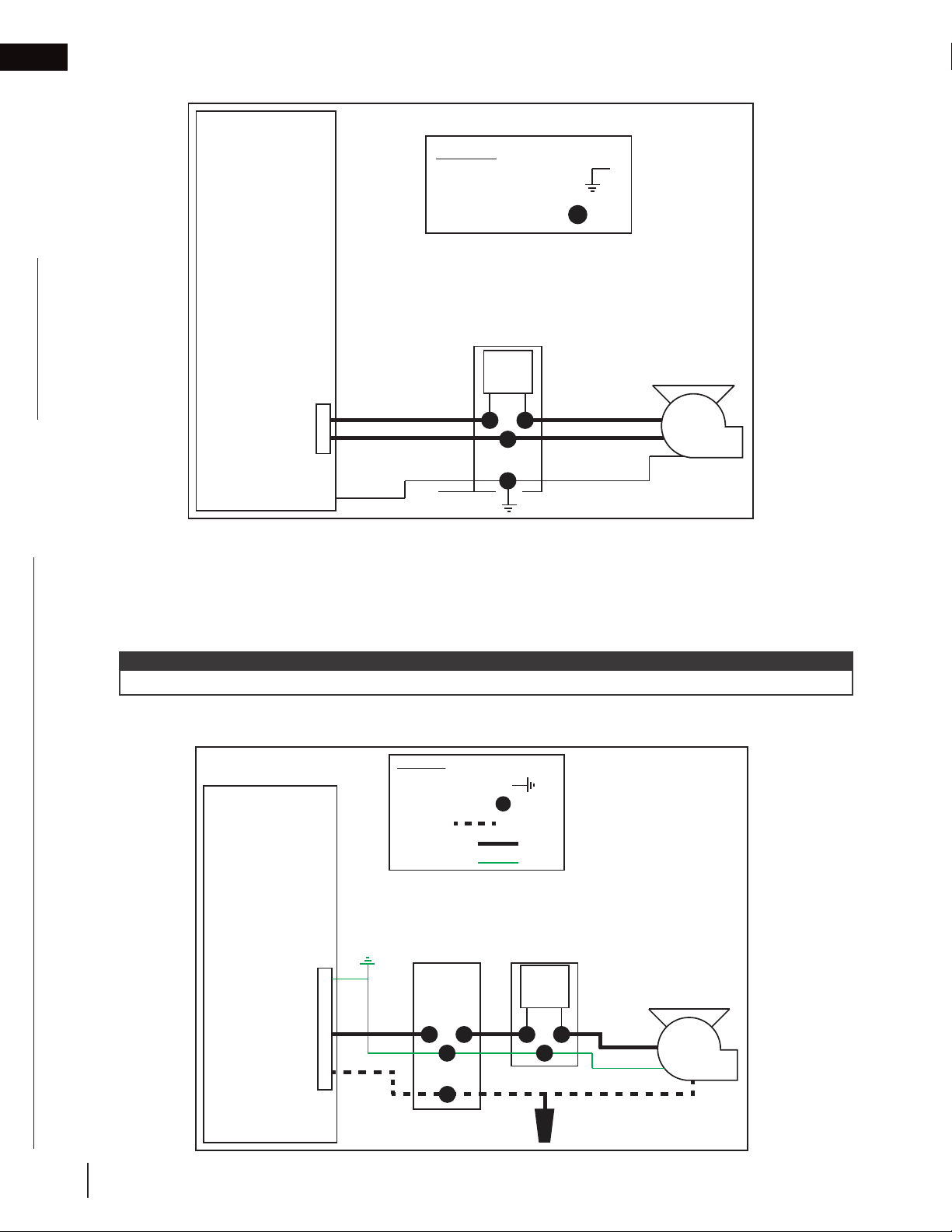
9.1 wiring to SIT control board & remote control
BLOWER
BLOWER/LAMP
TERMINAL BLOCK
LAMP
COMFORT
FAN
COMFORT
FAN
LAMP
APPLIANCE CONTROLLER
BLOWER
1. Unplug the blower / lamp terminal block on the SIT control
board, located in the appliance (see appliance manual for
details).
2. Determine the desired location of the wiring knockout (Fig. 1),
and then remove the left or right knockout accordingly. Install
bushing (supplied) into knockout.
3. Loosen blower terminal screws and disconnect wires.
4. Disconnect the blower ground wire, which is screwed to the
base of the appliance.
5. Connect new armoured cable (not supplied) into the blower
terminal block and tighten the blower terminal screws.
6. Plug the blower / lamp terminal block back into the board.
note:
Ensure to ground new armoured cable to the ground screw.
x 1
Right Side
Knockout
REMOVE WIRES TWO BLOWER
WIRES AS SHOWN
Blower
BLOWER/LAMP TERMINAL
BLOCK (TOP VIEW)
Back View of Appliance
Lamp
Left Side
Knockout
Fig. 1
26
7. If applicable, remove the 4 screws securing the decorative cover on the blower housing assembly and set
them aside (Fig. 4, next page). Remove the decorative cover and set it aside.
W415-1789 / C / 01.29.19
Page 27

electrical information
#10 Thread, RH
29/64”
1/8”
1-1/2”
Quadrex Drive
Hex
Hex
8. If applicable, remove the 4 screws securing the inline cover assembly and set them aside (Fig. 3). Remove
the inline cover assembly and set it aside.
9. Install the on/off switch into the on/off switch housing with 2 screws (supplied).
10. Install the pal nut and knob.
11. Install the new armoured cable from the SIT control board to the on/off switch housing inside the blower kit
housing.
12. Connect the hot wire of the new armoured cable to one end of the on/off switch inside the on/off switch
housing.
note:
Ensure to use armoured cable, connectors, and strain reliefs suitable for installation (not supplied).
Armoured cable should be installed in a stud whenever possible. Armoured cable should also be installed as
close to the outside of the enclosure and as far away from the appliance as possible.
13. Connect the opposite end of the on/off switch to the black wire from the blower inside the on/off switch
housing.
14. Connect the neutral wire of the new armoured cable to the white wire from the blower inside the on/off switch
housing.
15. Connect the ground wires from the blower and armoured cable to the ground screw inside the on/off switch
housing.
16. Install the on/off switch housing into the blower kit housing by inserting the tabs into the slots (Fig. 2). Tighten
the nut onto the stud.
17. Install/reinstall the inline cover assembly using 4 screws (supplied) (Fig. 3).
18. Install/reinstall the decorative cover onto the blower housing assembly using 4 screws (supplied) (Fig. 4).
x2
EN
Stud
Nut
Some components
hidden for clarity.
#9-14 Thread, RH
x 4
Fig. 2
#9-14 Thread, RH
x 4
Fig. 3
Fig. 4
W415-1789 / C / 01.29.19
27
Page 28
EN
electrical information
9.1.1 wiring diagram
SIT
Proflame 2
Control Board
14/2 power source
(not supplied)
L
N
Legend:
Ground Connection =
Field Connection =
On/Off Switch
in Blower
Housing
On/Off
Switch
(factory installed)
(supplied)
Blower
9.2 wiring to wall switch & remote control (in series)
1. Determine the location for the wall switch. Install an electrical box (not supplied) at the location.
2. Ensure the hot and neutral wires from the Proflame 2 are properly connected to the wall switch box.
3. Connect the hot wire from the on/off switch to the wall switch.
4. Connect the neutral wires to each other from the blower to the power source neutral (N).
5. Connect the all ground from the SIT Proflame 2 control board to the blower.
note:
Check the blower specifications (see “blower specifications” section) before choosing a suitable wire size.
9.2.1 wiring diagram
Legend:
Ground Connection =
Field Connection =
Neutral =
L1 (120VAC) =
Ground Wire =
SIT
Proflame 2
Control Board
G
Wall
Switch
On/Off Switch
in Blower
Housing
On/Off
Switch
28
W415-1789 / C / 01.29.19
L
N
Blower
Page 29

electrical information
9.3 wiring to wall switch only
1. Turn off the power by locating your housebreaker, and shutting the power off to the room you will be working
in.
2. Determine the location for the wall switch (not supplied). Install an electrical box (not supplied) at the location.
3. Ensure the wires for the wall are properly wired to the switch box and are ready.
4. Connect the hot wire from the on/off switch to the wall switch.
5. Connect the neutral wires to each other from the blower to the power source neutral (N).
6. Connect the all ground from the power source to the blower.
note:
Check the blower specifications (see “blower specifications” section) before choosing a suitable wire size.
9.3.1 wiring diagram
Legend:
Ground Connection =
Field Connection =
Neutral =
L1 (120VAC) =
Ground Wire =
On/Off Switch
in Blower
Housing
Wall
Switch
On/Off
Switch
Blower
120VAC
14/2
Power
Source
G
L
N
EN
9.4 blower specifications
00464504 00469142
Assembled in Mexico
115 V 50/50Hz Class B
0.9A/1.1A 1600 RPM
Cust P/N Sealed Ball Brg
Thermally Protected
No. 70903602
TYPE 90B1
AO
Connection Diagram
Wht Line
Blk Line
Blu
Blu
4 MFD/370 VAC
61299553
W415-1789 / C / 01.29.19
29
Page 30

EN
10.0 operation
10.1 on/off switch
!
WARNING
• This should be performed after both the appliance and DHC™ Plus have been fully installed, including all
venting and finishing materials.
For optimal performance, the on/off switch in the blower housing must ALWAYS be set to the maximum speed
setting.
note:
If a lower speed is selected (at the blower housing or remote) to reduce air flow, the result may be a minor
imbalance of the motor that causes a minor humming. While this will not affect the longevity of the motor, it may
result in a noticeable noise depending on the location of the DHC™ Plus blower kit.
10.2 using remote control
The remote control has 5 different blower speed settings. For optimal performance, the remote control must
ALWAYS be set to the maximum speed setting.
note:
If a lower speed is selected (at the blower housing or remote) to reduce air flow, the result may be a minor
imbalance of the motor that causes a minor humming. While this will not affect the longevity of the motor, it may
result in a noticeable noise depending on the location of the DHC™ Plus blower kit.
30
W415-1789 / C / 01.29.19
Page 31

11.0 replacement parts
WARNING
!
• Failure to position the parts in accordance with this manual or failure to use only parts specifi cally approved
with this appliance may result in property damage or personal injury.
Contact your dealer for questions concerning prices and policies on replacement parts. Normally, all parts can
be ordered through your Authorized dealer / distributor.
For warranty replacement parts, a photocopy of the original invoice will be required to honour the
claim.
When ordering replacement parts always give the following information:
• Model & Serial Number of appliance
• Installation date of appliance
• Part number
• Description of part
• Finish
Parts, part numbers, and availability are subject to change without notice.
Parts identifi ed as stocked will be delivered within 2 to 5 business days for most delivery
destinations.
Parts not identifi ed as stocked will be delivered within a 2 to 4 week period, for most cases.
Parts identifi ed as ‘SO’ are special order and can take up to 90 days for delivery.
EN
W415-1789 / C / 01.29.19
31
Page 32

EN
Items may not appear exactly as illustrated.
Part Number
Description
W010-4481-SER
Air damper assembly
3
4
Ref. No.
Part Number
7
6
2122232527
26
W062-0078-SER
DHC™ Plus blower
W660-0113
W010-4544
Ye s
W010-4482-SER
5
Gasket
W290-0876-SER
8
W350-0908-SER
Inline housing
W010-4483-SER
Collar plate assembly
28
replacement parts
11.1 DHCP-BK overview
32
W415-1789 / C / 01.29.19
Page 33

replacement parts
Part Number
Description
Stocked
2
21
22
W263-0214-SER
Wall flashing
W200-0764-SER
1
EN
11.2 DHCP-EK overview
W415-1789 / C / 01.29.19
33
Page 34

EN
Items may not appear exactly as illustrated.
Ref. No.
Part Number
Description
Stocked
21
22
W263-0213-SER
Wall flashing
W305-0007-SER
Louvered grill
replacement parts
11.3 DHCP-HK overview
34
W415-1789 / C / 01.29.19
Page 35

12.0 notes
EN
W415-1789 / C / 01.29.19
35
Page 36

NAPOLEON CELEBRATING OVER 40 YEARS
OF HOME COMFORT PRODUCTS
7200, Route Transcanadienne, Montréal, Québec H4T 1A3
24 Napoleon Road, Barrie, Ontario, Canada L4M 0G8
214 Bayview Drive, Barrie, Ontario, Canada L4N 4Y8
103 Miller Drive, Crittenden, Kentucky, USA 41030
Phone: 1-866-820-8686
napoleon.com
Page 37

MODÈLES DE GAZ NATUREL
DHCP-BK / DHCP-EK / DHCP-HK
MODÈLES DE PROPANE
ADD PRODUCT CODE HERE (TRADE GOTHIC LT STD FONT)
FRANÇAIS
FRANÇAIS
MANUEL D’INSTALLATION
CONSIGNES DE SÉCURITÉ
AVERTISSEMENT!
RISQUE D’INCENDIE OU D’EXPLOSION
Incapacité à suivre ces avertissements
exactement peuvent entraîner de grave
blessures, des pertes de vie ou des
dommages matériels.
- N’entreposez pas et n’utilisez pas d’essence
ou autres liquides et vapeurs infl ammables à
proximité de cet appareil ou tout autre appareil.
- QUE FAIRE SI VOUS DÉTECTEZ UN
ODEUR DE GAZ:
• N’allumez aucun appareil.
• Ne touchez à aucun interrupteur
électrique; n’utilisez aucun téléphone dans
votre immeuble.
• Appelez immédiatement votre fournisseur
de gaz d’un téléphone voisin. Suivez ses
instructions.
• Si vous ne pouvez pas rejoindre votre
fournisseur de gaz, appelez le service des
incendies.
- L’installation et l’entretien doivent être faits par
un installateur qualifi é, une agence d’entretien
ou le fournisseur.
ADD MANUAL TITLE
ET D’OPÉRATION
Product Name / Code
(MUST use title from Price Book)
ADD ____ ILLUSTRATED
MD
BREVET DÉPOSÉ
ADD PRODUCT IMAGE
Cet appareil peut être installé dans une maison
préfabriquée (mobile) déjà installée à demeure
si les règlements locaux le permettent.
Cet appareil doit être utilisé uniquement
avec le type de gaz indiqué sur la plaque
Laissez ce manuel avec l’appareil.
d’homologation. Cet appareil ne peut être
converti à d’autres gaz, sauf si une trousse de
Conservez ce manuel pour consultation
conversion est utilisée.
ASSUREZ-VOUS DE COMMANDER LES EN-
SEMBLES CORRECTES. VOIR L’INTÉRIEUR
$10.00
Laissez ce manuel avec l’appareil
Conservez ce manuel pour consultation
INSTALLATEUR:
PROPRIÉTAIRE:
ultérieure.
INSTALLATEUR:
PROPRIÉTAIRE:
POUR PLUS DE DÉTAILS.
ultérieure
Wolf Steel Ltd., 24 Napoleon Rd., Barrie, ON, L4M 0G8 Canada / 103 Miller Drive, Crittenden, Kentucky, USA, 41030
Téléphone 1(866)820-8686 • www.napoleon.com • hearth@napoleon.com
DHCP-BK &
DHCP-EK Illustrée
Ces instructions DOIVENT être utilisées conjointement avec
les manuels d’installation des appareils Vector
CERTIFIÉ SELON LES NORMES NATIONALES CANADIENNES ET AMÉRICANES:
CSA 2.22 ET ANSI Z21.50 POUR LES APPAREILS À GAZ DÉCORATIF À ÉVACUATION
LuxuriaMD, et du système Dynamic Heat ControlMD.
POUR USAGE INTÉRIEUR SEULEMENT
MD
et
À UTILISER AVEC LES MODÈLES
VECTORMD (avec système DHCMD) &
LUXURIAMD SEULEMENT
IF INSTALLATION + OPERATION, ADD SERIAL
CSA /
INTERTEK
LOGO
LV38N/P-1 / LV38N/P2-1 / LV50N/P-2 / LV50N/P2-2 /
IF SEPARATE MANUALS, ADD “PLACE
LVX38N/P / LVX38N/P2 / LVX50N/P / LVX50N/P2 /
BARCODE LABEL ON THE OWNER’S MANUAL”
NUMBER LABEL HERE
LV62N/P / LV62N/P2 / LV74N / LV74N2
LVX62N/P / LVX62N/P2 / LVX74N / LVX74N2
W415-1789 / C / 01.29.19
Page 38

table des matières
1.0 planification de l’installation 39
FR
1.1 introduction 39
1.2 options d’installation 40
1.3 vue d’ensemble du système
DHCMD Plus 40
1.3.1 DHCP-BK 41
1.3.2 DHCP-EK 41
1.3.3 DHCP-HK 41
1.4 considérations du niveau de bruit 42
1.5 ventilation & conduits 42
1.6 emplacement dans l’enceinte 43
1.7 dimensions 44
1.7.1 DHCP-BK & DHCP-EK 44
1.7.2 DHCP-BK & DHCP-HK 44
2.0 exigences minimales des
conduits 45
2.1 sortie des conduits pour le
système DHCMD Plus 45
3.0 pré-installation sur un mur
extérieur, à l’intérieur de l’enceinte
ou hors de l’enceinte 46
4.0 installation sur un mur extérieur 47
4.1 vue d’ensemble de l’installation
sur un mur extérieur 47
4.2 exigences minimales en matière
d’ossature 48
4.3 liste de vérification de l’installation 50
5.0 installation sur un mur extérieur
hors de l’enceinte 51
5.1 vue d’ensemble de l’installation
sur un mur extérieur hors de l’enceinte
51
5.2 exigences minimales en matière
d’ossature 52
5.3 installation des conduits 52
5.4 liste de vérification de l’installation 53
6.0 options de fixation 54
6.1 installation à égalité 54
6.2 dépassant 55
6.3 surface 56
7.0 pré-installation en ligne hors de
l’enceinte 57
8.0 installation en ligne hors de
l’enceinte 58
8.1 vue d’ensemble de l’installation en
ligne hors de l’enceinte 58
8.2 exigences minimales en matière
d’ossature 59
8.3 installation des conduits 61
8.4 liste de vérification de l’installation 62
9.0 information électrique 63
9.1 câblage aux panneau de commande
SIT & télécommande 63
9.1.1 schéma de câblage 65
9.2 câblage à l’interrupteur de mur &
télécommande (en séries) 65
9.2.1 schéma de câblage 65
9.3 câblage à l’interrupteur de mur
seulement 66
9.3.1 schéma de câblage 66
9.4 spécifications du ventilateur 66
10.1 l’interrupteur « on/off» 67
10.2 fonctionnement de télécommande 67
10.0 fonctionnement 67
11.0 pièces de rechange 68
11.1 vue d’ensemble de DHCP-BK 69
11.2 vue d’ensemble de DHCP-EK 70
11.3 vue d’ensemble de DHCP-HK 71
38
note:
L’information contenue dans ce manuel est jugée correcte au moment de l’impression. Wolf Steel Ltd. se réserve
le droit de modifier ou de modifier toute information contenue dans ce manuel à tout moment sans préavis. Les
modifications, autres que les éditoriaux, sont désignes par une ligne verticale dans la marge.
!
AVERTISSEMENT:
chrome qui, selon l’État de Californie, causeraient le cancer, et des substances chimiques
incluant le toluène qui, selon d’État de Californie, causeraient des malformations congénitales
ou autres dangers pour la reproduction.
Pour de plus amples renseignements, visitez le www.P65Warnings.ca.gov.
W415-1789 / C / 01.29.19
Ce produit peut vous exposer à des substances chimiques incluant le
Page 39

1.0 planification de l’installation
!
AVERTISSEMENT
Le système Dynamic Heat ControlMD Plus (DHCMD Plus) NE PEUT PAS être installé si l’appareil n’est pas
doté du système Dynamic Heat ControlMD.
• Le système DHCMD Plus est UNIQUEMENT compatible avec l’option d’installation n° 2 du système
Dynamic Heat ControlMD (ouverture avant) ou l’option d’installation n° 3 (ouverture à l’arrière).
Le système DHCMD Plus DOIT être installé avec une sortie d’air; autrement, l’appareil présentera un risque
d’incendie.
• L’installation doit être conforme aux codes locaux ou, en l’absence de tels codes, au Code d’installation du
gaz naturel et du propane CSA B149.1 au Canada ou au National Fuel Gas Code ANSI Z223.1 / NFPA 54 aux
États-Unis.
• Un appareil peut être doté d’un seul ventilateur DHCMD Plus.
• Nous recommandons d’installer le système DHCMD Plus AVANT d’installer les conduits d’évacuation et les
conduits de gaz de l’appareil.
• L’installation DOIT être effectuée par un installateur qualifié qui a suivi le cours sur le système Dynamic Heat
ControlMD sur Napoleon EDucation, le portail de formation en ligne de Napoléon.
• Assurez-vous que l’appareil est complètement refroidi avant de commencer l’installation.
• Afin d’éviter les risques de suffocation, gardez le sac d’emballage loin des bébés et des jeunes enfants. Ne le
laissez pas traîner dans les berceaux, les lits, les poussettes, ou les parcs de jeu. Ce sac n’est pas un jouet.
Nouez-le avant de le jeter.
1.1 introduction
Le système Dynamic Heat ControlMD Plus (DHCMD Plus) est un système de gestion de la chaleur produite par
l’appareil et autour de celui-ci. Le système DHCMD Plus vise à éloigner la chaleur de l’appareil et principalement à
distribuer tout ou partie d’elle à l’extérieur. Lorsque la longueur de conduit est supérieure à cinq pieds ou lorsque les
conduits doivent passer par des espaces non isolés (comme dans un grenier), il est recommandé d’isoler les conduits.
FR
Bien qu’il soit possible d’utiliser le système DHCMD Plus pour déplacer la chaleur vers un autre
emplacement dans la maison, veulliez considéré soigneusement les points suivants lors de la phase de
planification:
• Le niveau sonore du ventilateur DHC
section « considérations du niveau de bruit »).
• Le système DHCMD Plus ne doit pas être utilisé dans de
petites pièces fermées avec des plafonds bas, comme une
petite salle de bain, car la pièce sera rapidement pressurisée
et le transfert de chaleur du foyer sera réduit / éliminé.
• Le système DHCMD Plus déplace presque toute la chaleur
utilisable. Si le volume de la pièce est petit, la pièce peut
rapidement devenir très chaude. Vous pouvez déplacer la
chaleur non désirée d’une pièce à une autre, ce qui risque de ne pas convenir au client. Il est donc important
de bien évaluer la quantité de chaleur et la taille de la pièce dans laquelle la chaleur est transférée avant de
commencer l’installation.
• Lorsque le système DHCMD Plus est utilisé pour transférer de la chaleur dans une autre pièce, il est
recommandé d’installer un interrupteur marche / arrêt dans cette pièce afin que le transfert de chaleur puisse
être désactivé à distance, si désiré. Le système DHCMD Plus ne comprend pas de thermostat.
MD
Plus est semblable à celui d’un ventilateur de salle de bain (voir la
BREVET DÉPOSÉ
W415-1789 / C / 01.29.19
39
Page 40

planification de l'installation
Hex
Hex
Hex
29/64”
1/8”
1-1/2”
FR
1.2 options d’installation
Il y a trois options d’installation possibles pour le système DHCMD Plus, chacune ayant ses avantages:
Installation sur une mur extérieur
Dans cette option, l’installation du système DHCMD Plus se fait sur le mur extérieur de l’enceinte de l’appareil.
Il ne nécessite pas d’évacuation ni de conduit ni de cloison, et est donc l’option d’installation la plus simple.
Cependant, assurez-vous de considérer le bruit de circulation d’air de l’ensemble de ventilateur DHCMD Plus.
Pour plus de détails, consultez les sections « considérations du niveau de bruit » et « installation sur un mur
extérieur ».
Installation sur une mur extérieur hors de l’enceinte
Dans cette option, l’installation du système DHCMD Plus se fait sur un mur extérieur, hors de l’enceinte de
l’appareil. Bien qu’elle nécessite des conduits et une cloison, la distance à laquelle le ventilateur peut être installé
permet de réduire le bruit de circulation d’air de façon significative. Pour plus de détails, consultez les sections «
considérations du niveau de bruit » et « installation sur un mur extérieur hors de l’enceinte ».
Installation en ligne hors de l’enceinte
Dans cette installation, le système DHCMD Plus est installé en ligne hors de l’enceinte, n’importe où entre
l’enceinte de l’appareil et l’ensemble d’évacuation d’air chaud. Comme avec l’installation sur un mur extérieur
hors de l’enceinte, cette installation nécessite une évacuation, une cloison ainsi que l’ajout de conduits. Cette
installation offre le plus de possibilités pour des configurations uniques, y compris à travers plusieurs pièces ou
étages. Pour plus de détails, consultez la section « installation en ligne hors de l’enceinte ».
Le tableau ci-dessous comporte les ensembles requis pour chaque option d’installation. Veuillez lire
attentivement.
Type d’Installation DHCP-BK DHCP-EK DHCP-HK
Mur extérieur
Installation sur un mur extérieur
hors de l’enceinte
Installation en ligne hors de l’enceinte
1.3 vue d’ensemble du système DHCMD Plus
Contenu de chaque ensemble:
DHCP-BK DHCP-EK DHCP-HK
1 x boîtier de ventilateur
1x
l’assemblage du panneau d’accès en ligne
1 x registre d’air
1 x interrupteur « on/off» / boîtier
1 x connecteur de collet
1 x plaque de collet
2 x support de montage
1 x bague
13 x vis #9x1/2 po
7 x vis #8x1/2 po
1 x boîtier extérieur
1 x solin mural
1 x couvercle décoratif
12 x vis #9x1/2 po
N/A
N/A
N/A
1 x ensemble d’évacuation d’air
chaud
1 x solin mural
4 x vis #9x1/2 po
2 x vis #10x1-1/2 po
Quadrex Drive
#10 Thread, RH
note:
Ces ensembles complets sont toujours composés d’au plus deux boîtes. Veuillez lire le manuel d’installation attentivement et veiller à commander les bons ensembles d’installation.
Bien qu’il ne soit pas fourni, il vous faudra un câble armé pour le câblage du système DHCMD Plus (consultez
la section « information électrique » pour plus de détails). Assurez-vous d’avoir suffisamment de câbles armés à
votre disposition pour compléter votre installation.
40
W415-1789 / C / 01.29.19
Page 41

Hex
1.3.1 DHCP-BK
0.141”
Hex
1
#9-14 Thread, RH
Réf. Description Réf. Description
1 Ensemble de quincaillerie 5 Plaque de collet
2 Interrupteur à vitesse variable (avec
3 Registre d’air 7 L’assemblage du panneau d’accès en ligne
4 Supports (x2) 8 Boîtier de ventilateur
1.3.2 DHCP-EK
2
boîtier et écrou)
planification de l'installation
3
1 3 4
4 5
2
6
6 Connecteur de collet
9 Bague
FR
7
8
9
1.3.3 DHCP-HK
Réf. Description Réf. Description
1 Ensemble de quincaillerie 3 Boîtier extérieur
2 Couvercle décoratif 4 Solin mural
1
#9-14 Thread, RH
29/64”
1/8”
1-1/2”
#10 Thread, RH
Quadrex Drive
2
3
Réf. Description Réf. Description
1 Ensemble quincaillerie 3 Ensemble d’évacuation d’air chaud
2 Solin mural
W415-1789 / C / 01.29.19
41
Page 42

planification de l'installation
FR
1.4 considérations du niveau de bruit
Plus
MD
Plus utilise un ventilateur de haute performance pour déplacer la chaleur non désirée à
Le système DHC
l’extérieur. Semblable à un ventilateur de salle de bain ou à une hotte de cuisinière, l’utilisation d’un ventilateur
pour déplacer l’air produire un son.
note:
Déterminez l’emplacement de l’ensemble du ventilateur avec soin, car le bruit du débit d’air émis par ce dernier
est plus perceptible lorsqu’il est situé à proximité de l’appareil et du client. Ceci est particulièrement important si
vous utilisez le ventilateur pour transférer la chaleur à l’intérieur d’une maison.
1.5 ventilation & conduits
Selon le type d’installation, le système DHCMD Plus nécessitera des des conduits qui ne sont pas fournis:
Installation sur une Mur Extérieur
• N/A
Installation sur une Mur Extérieur hors de l’Enceinte
• Un composant d’évacuation rigide en acier de 6 po entre l’enceinte de l’appareil et l’ensemble de ventilateur
DHC
MD
Installation en Ligne hors de l’Enceinte
• Un conduit en acier de 6 po entre l’enceinte de l’appareil et l’ensemble de ventilateur DHC
• Un composant d’évacuation rigide en acier de 6 po entre l’ensemble de ventilateur DHCMD Plus et l’ensemble
d’évacuation d’air chaud
note:
Assurez-vous de consulter toujours les codes locaux avant d’installer le système DHCMD Plus.
MD
Plus
42
W415-1789 / C / 01.29.19
Page 43

planification de l'installation
1.6 emplacement dans l’enceinte
AVERTISSEMENT
!
• NE PAS couvrir ou placer d’objets dans les ouvertures du sortie d’air Dynamic Heat ControlMD. Cela permettra à
l’appareil de manière incorrecte et peut causer un risque d’incendie.
• Assurez-vous que le débit d’air dans la zone de l’enceinte n’est pas restreint d’aucune façon à l’exception de
l’évacuation approuvée ou le système
Le système DHCMD Plus tire l’air de l’enceinte de l’appareil et doit être installé dans l’enceinte, au-
dessus de l’appareil. NE raccordez JAMAIS le système directement à l’appareil.
Zone d’installation recommandée pour la plaque de collet du système DHCMD Plus - dans la section de
12 po (30,5cm) qui se trouve dans le haut de l’enceinte.
Aucun autre type de matériaux ne peut remplir cet espace; seul un système d’évacuation approuvé peut y
être installé ou le système DHCMD Plus.
DHCMD Plus.
sommet de l’enceinte / plafond
FR
Ouverture de
*
sortie d’air
Dynamic Heat
Control
Goujon
Impasse
Cadre
Supérieur
Déflecteur
important:
** La plaque de collet du système DHCMD Plus doit être installer au dessus du bouclier d’évacuation de
l’appareil (non illustré) (33 po [83cm] minimum du haut de l’appareil).
MD
* *
3 po
33 po
(83cm)
minimum
au dessus
de
l’appareil
**
Seul Côté
Seul Côté
(Encastré)***
*
Voir à Travers
*
33 po
(83cm)
minimum
au dessus
de
l’appareil
**
Seul Côté
(Encastré
Extérieur)
*** Des restrictions s’appliquent également à see-thru lorsqu’une ou plusieurs cavités sont utilisées. Consultez le
manuel de votre appareil pour plus de détails.
Le débit d’air dans la zone hachurée ne doit pas être restreint d’aucune façon à l’exception d’un système
d’évacuation approuvée ou le système DHCMD Plus. Aucun autre élément n’est autorisé dans ce domaine.
Consultez le manuel de votre appareil pour plus de détails à propos des dégagements aux matériaux combustibles. Aucun matériau combustible n’est autorisé dans la zone hachurée ou dans l’espace entre les plots (c’est-àdire sans câblage, conduits, perçages électriques, éléments de charpente combustibles, etc.).
W415-1789 / C / 01.29.19
43
Page 44

planification de l'installation
REV.
025435
C
B
D
8
REV.
DHCP-BK
C
B
D
8
REV.
DHCP-HK
C
B
D
8
FR
1.7 dimensions
1.7.1 DHCP-BK & DHCP-EK
POUR UNE INSTALLATION SUR UN MUR EXTÉRIEUR ET SUR UN MUR
EXTÉRIEUR HORS DE L’ENCEINTE SEULEMENT
vue de face vue de côté droite
15/16"
25mm
16 3/4"
425mm
18 1/2"
469mm
14 1/16"
357mm
16"
406mm
1.7.2 DHCP-BK & DHCP-HK
POUR UNE INSTALLATION EN LIGNE HORS DE L’ENCEINTE SEULEMENT
DHCP-BK
vue de face vue de côté droite
3 3/16"
81mm
6"
152mm
13mm
13 3/16"
335mm
1/2"
14 3/16"
360mm
22mm
7/8"
19 15/16"
507mm
1 1/2"
38mm
FIXATION AJUSTABLE AFFLEURANTE PAR TRANCHE
ADJUSTABLE FROM FLUSH TO SURFACE MOUNT IN
1 1/2" INCREMENTS. (SHOWN 1 1/2" PROUD OF
DE 1 1/2 PO [ILLUSTRÉ À 1 1/2 PO DU MATÉRIAU DE
FINISHING IN THIS DIAGRAM)
FINITION DANS CE SCHÉMA]
3 1/2"
90mm
11 11/16"
297mm
1 1/2"
[40mm]
168mm
6 3/16"
157mm
6 5/8"
vue de dessus
8 1/4"
209mm
6"
152mm
vue de dessus
8"
199mm
6"
152mm
9 7/8"
251mm
9 5/16"
236mm
1 13/16"
45mm
1 13/16"
46mm
44
362mm
DHCP-HK
vue de face vue de côté droite
12 11/16"
322mm
W415-1789 / C / 01.29.19
102mm
14 1/4"
14 1/2"
368mm
16"
406mm
4"
3/4"
19mm
6"
152mm
3 7/8"
98mm
vue de dessus
279mm
11"
13/16"
21mm
5 13/16"
148mm
1 1/2"
38mm
5 9/16"
142mm
7 3/16"
183mm
6"
152mm
1 13/16"
46mm
102mm
4"
Page 45

2.0 exigences minimales des conduits
2.1 sortie des conduits pour le système DHCMD Plus
note:
Les terminaux du mur sont à des fins
d’illustration seulement. La taille et les
formes peuvent varier.
B
G
C
D
M
C
FR
D
L
E
G
A
H
INSTALLATIONS
CANADA É.-U.
12” (30,5cm) 12” (30,5cm) Dégagement au-dessus du sol, d’une véranda, d’une terrasse en vois ou d’un balcon.
A
12” (30,5cm)* 12” (30,5cm)* Dégagement des fenêtres.
B
C
D
E
F
G
H
I
J
K
12”
(30,5cm)**
12” (30,5cm)** 12” (30,5cm)** Dégagement d’un soffite non ventilé.
0” (0mm) 0” (0mm) Dégagement des murs faisant coin extérieur.
0” (0mm) 0” (0mm)
2” (51mm) 2” (51mm)
3’(0,9m) 3’(0,9m)****
3’ (0,9m) 3’ (0,9m)**** Dégagement d’évent du régulator.
12” (30,5cm) 9” (229mm)
6’ (1,8m) 3’ (0,9m) † Dégagement d’une prise d’air mécanique.
7’ (2,1m) ‡ 7’ (2,1m) **** Dégagement au-dessus d’un trottoir ou d’une entrée pavée situées sur une propriété publique.
12”
(30,5cm)**
Dégagement verticale d’un soffite ventilé situé au-dessus de la terminaison si la distance horizontale est
de moins de 2’ (0,6m) de la ligne médiane de la terminaison.
Dégagement des murs extérieurs incombustibles faisant coin intérieur ou aux obstructions incombustibles (cheminée, etc.)
Dégagement des murs extérieurs combustibles faisant coin intérieur ou aux obstructions combustibles (habillage extérieur, etc.)
Dégagement horizontale de chaque côté depuis la ligne verticale tirée du centre d’un ensemble de
régulateur/compteur pour une distance verticale maximale de 15’ (4,6m).
Dégagement d’une prise d’air de ventilation non mécanique de la maison ou d’une prise d’air de combustion de
tout autre appareil.
F
I
J
K
12” (30,5cm)**** 12” (30,5cm)**** Dégagement sous une véranda ou une terrasse en bois.
L
1’ (0,3m)†* 1’ (0,3m) †* Dégagement des murs adjacents, inclueant les maisons voisines.
M
* Recommandé afin de prévenir la formation de buée dans les fenêtres et les cassures thermiques.
** Il est recommandé d’utiliser un protecteur de chaleur et de maximiser la distance au soffite de plastique.
**** Ceci est une distance recommandée. Vérifiez les codes locaux pour connaître les contraintes additionelles.
† 3 pieds au-dessus si la distance horizontale est de moins de 10 pieds.
Une terminaison d’évacuation ne doit pas être installée à un endroit où elle pourrait causer une formation dangereuse de givre ou de
‡
glace sur les surfaces d’une propriété adjacente.
†† Permis seulement si la véranda ou la terrasse en bois sont complètement ouverts sur un minimum de deux côtés sous le plancher.
†* Recommandé pour service. Vérifiez les codes locaux pour connaître les contraintes additionelles.
note:
Les dégagements doivent être conformes aux codes d’installation locaux et les exigences du fournisseur de gaz. En leur absence, les dégagements doivent être comme indique ci-dessous et sont basés sur des codes nationaux.
W415-1789 / C / 01.29.19
45
Page 46

Hex
3.0 pré-installation sur un mur extérieur, à l’intérieur de
FR
l’enceinte ou hors de l’enceinte
POUR UNE INSTALLATION SUR UN MUR EXTÉRIEUR, ET SUR UN MUR
EXTÉRIEUR HORS DE L’ENCEINTE SEULEMENT
Pour une installation sur un mur extérieur, et sur un mur extérieur hors de l’enceinte, suivez les instructions cidessus avant de commencer l’installation. Pour un installation en ligne hors de l’enceinte, consultez la section «
pré-installation en ligne de l’enceinte ».
1. Insérez le boîtier du ventilateur dans le boîtier extérieur. Assurez-vous la bonne orientation (Fig. 1).
note:
Nous vous recommandons d’attendre d’avoir installé tout le câblage électrique pour poser l’assemblage du
panneau d’accès en ligne et le couvercle décoratif à la toute fin. Pour les instructions d’installation, consultez
la section « information électrique ».
2. Fixez le boîtier du ventilateur au boîtier extérieur à l’aide de quatre vis (fournies) (Fig. 2).
x 4
Fig. 1
3. Installez le registre d’air sur le collet, puis fixez-le à l’aide de vis autoperceuses (fournies (Fig. 3). Faites tourner
l’assemblage jusqu’à ce que le registre se ferme lorsque le ventilateur ne fonctionne pas.
note:
Le registre d’air doit se fermer lorsque le ventilateur ne fonctionne pas pour que le système fonctionne
correctement.
La plaque du
registre d’air doit
x 3
Fig. 3
s’ouvrir vers le
bas. Veillez à
installer dans le
bon sens afin
qu’il s’ouvre
lorsque le venti-
IMPORTANT
lateur fonctionne.
Testez toujours
avant de
terminer.
Fig. 2
Plaque
Vue de Profil
46
W415-1789 / C / 01.29.19
Page 47

4.0 installation sur un mur extérieur
4.1 vue d’ensemble de l’installation sur un mur extérieur
!
AVERTISSEMENT
• Afin d’éviter un risque d’incendie grave, les dégagements minimaux aux matériaux combustibles doivent être
maintenus.
• NE couvrez PAS la sortie d’air du système Dynamic Heat ControlMD et ne déposez pas d’objets sur celle-ci. Le
non-respect de ces instructions pourrait augmenter le risque d’incendie.
Le système DHCMD Plus NE PEUT PAS être directement fixé au-dessus ni en dessous de la
terminaison d’évacuation, car cela entraînera la défaillance du système. Le système DOIT être fixé à
gauche ou à droite de la terminaison d’évacuation.
• Pour une performance optimale, nous recommandons d’installer le système DHCMD Plus dans le section de
12 po (30,5cm) qui se trouve dans le haut de l’enceinte. Cependant, il DOIT être installé au-dessus de
l’appareil.
• La hauteur minimale de l’espace se trouvant au-dessus de l’appareil variera selon la taille de l’appareil.
Consultez la section « exigences d’évacuation minimales » du manuel de votre appareil pour obtenir de plus
amples détails.
L’installation du système DHCMD Plus sur un mur extérieur constitue l’option d’installation la plus simple.
L’installation se fait sur le mur extérieur de l’enceinte de l’appareil.
FR
Ensembles Requis:
• DHCP-BK
• DHCP-EK
Boîtier de
Ventilateur
Registre
d’Air
note:
DOIT être dotée d’une sortie d’air.
note:
Le schéma ci-dessus est présente
à titre d’illustration seulement.
L’installation doit être conforme à
tous les codes locaux.
Solin
Mural
Couvercle
Décoratif
Terminaison
d’Évacuation
de l’Appareil
(s’il y a lieu)
View of Opposite
Vue du Mur
Exterior Wall
Extérieur Opposé
Extérieur
Boîtier
Extérieur
Enceinte
Appareil
SYSTÈME GLASS GUARD
GLASS GUARD
LVX38 illustrated
LVX38 illustré
Intérieur
Maintenir la
Maintain
distance aux
distance to
combustibles.
combustibles.
Isolation
W415-1789 / C / 01.29.19
47
Page 48

installation sur un mur extérieur
FR
4.2 exigences minimales en matière d’ossature
APPLICABLE POUR L’INSTALLATION SUR UN MUR EXTÉRIEUR,
ET SUR UN MUR EXTÉRIEUR HORS DE L’ENCEINTE
note:
Pour une performance optimale, nous recommandons d’installer le système DHCMD Plus dans la section de 12
po (30,5cm) qui se trouve dans le haut de l’enceinte. Le système DHCMD Plus doit être installé au dessus de
l’appareil.
Dégagements Minimaux aux Matériaux Combustibles Dégagement
DHCP-EK 0 po
Conduits d’évacuation, collets, coupe-feu, etc. 1 po (25mm)
1. Déterminez l’emplacement désiré du boîtier extérieur sur le mur extérieur, puis découpez et charpentez une
ouverture de 14 1/2 po (36,8cm) de large et de 17 1/4 po (44cm) de haut (Fig. 1).
Intérieur
Interior
14 1/2 po (36,8cm)
17 1/4 po (44cm)
Exterior
Extérieur
Installation sur un Mur Extérieur Illustré
Fig. 1
note:
Il peut être nécessaire de caler le boîtier du ventilateur dans l’ouverture brute afin de bien le fixer. Si le ventilateur
d’est pas bien fixé, du bruit excessif et de la vibration peuvent en résulter.
48
W415-1789 / C / 01.29.19
Page 49

installation sur un mur extérieur
2. Déterminez à quel point vous souhaitez que le système dépasse du mur extérieur fini, puis fixez le solin mural
à l’aide de quatre vis (fournies) (Fig. 2). Consultez la section « options de fixation » pour obtenir plus de
détails.
note:
Il est REQUIS de percer au préalable le boîtier extérieur à l’aide
d’un foret de 1/8 po avant de pouvoir installer le solin mural.
Pour éviter les égratignures, nous vous recommandons de faire
glisser le solin mural en partant de l’arrière.
Si vous installez votre système DHCMD Plus en surface, cette
étape est superflue (consultez la section « options de fixation »).
3. Fixez le boîtier extérieur au mur extérieur en installant le solin mural à l’aide des attaches appropriées (non
fournies) (Fig. 3).
4. Appliquez du silicone sur le joint après l’installation, et calfeutrez ou scellez le solin mural de manière correcte
pour le matériau de finition (Fig. 4).
Fig. 2
SILICONE
x 4
FR
Intérieur
CAULK
CALFEUTRAGE
Fig. 4
Extérieur
Installation sur un Mur Extérieur Illustré
5. Nous vous recommandons d’attendre d’avoir installé tout le câblage électrique pour poser l’assemblage du
panneau d’accès en ligne et le couvercle décoratif à la toute fin. Pour les instructions d’installation, consultez
la section « information électrique ».
Fig. 3
W415-1789 / C / 01.29.19
49
Page 50

installation sur un mur extérieur
FR
4.3 liste de vérification de l’installation
!
AVERTISSEMENT
• Assurez-vous que tous les éléments de votre installation soient vérifiés afin d’éviter tout risque d’incendie grave.
• L’installation complétée doit se conformer aux codes locaux. En l’absence de codes locaux, l’installation doit
être conforme au Code d’installation du gaz naturel et du propane CSA B149.1 au Canada, ou à la norme ANSI
Z223.1 / NFPA 54 du National Fuel Gas Code aux État-Unis.
Installateur, veuillez cocher toutes les cases correspondant à votre installation,
sinon l’installation N’EST PAS considérée comme terminée.
1. Ensemble DHCP-BK installé dans l’ensemble DHCP-EK.
2. Registre d’air installé et vérifié.
3. Ouverture brute charpentée dans le mur extérieur.
4. Solin mural installé et scellé de manière correcte pour le
matériau de finition .
5. Ensemble DHCP-EK fixé au mur extérieur.
6. L’assemblage du panneau d’accès en ligne installé (consultez la section « information électrique »).
7. Couvercle décoratif installé et l’opération du système
vérifié avec appareil (consultez la section « information
électrique »).
8. Câblage complété (consultez la section « information
électrique »).
9. Interrupteur « on/off » ajusté à « on » complètement.
DHCP-BK
DHCP-EK
Registre d’Air
Couvercle Décoratif
Solin Mural
Intérieur
Extérieur
50
W415-1789 / C / 01.29.19
Page 51

5.0 installation sur un mur extérieur hors de l’enceinte
5.1 vue d’ensemble de l’installation sur un mur extérieur hors de l’enceinte
!
AVERTISSEMENT
• Afin d’éviter un risque d’incendie grave, les dégagements minimaux aux matériaux combustibles doivent être
maintenus.
• NE couvrez PAS la sortie d’air du système Dynamic Heat ControlMD et ne déposez pas d’objets sur celle-ci. Le
non-respect de ces instructions pourrait augmenter le risque d’incendie.
Le système DHCMD Plus NE PEUT PAS être directement fixé au-dessus ni en dessous de la
terminaison d’évacuation, car cela entraînera la défaillance du système. Le système DOIT être fixé à
gauche ou à droite de la terminaison d’évacuation.
• Pour une performance optimale, nous recommandons d’installer le système DHCMD Plus dans le section de
12 po (30,5cm) qui se trouve dans le haut de l’enceinte. Cependant, il DOIT être installé au-dessus de
l’appareil.
• La hauteur minimale de l’espace se trouvant au-dessus de l’appareil variera selon la taille de l’appareil.
Consultez la section « exigences d’évacuation minimales » du manuel de votre appareil pour obtenir de plus
amples détails.
Le système DHCMD Plus peut être installé hors de l’enceinte de l’appareil, jusqu’à une distance maximale de 60 pi
(18,2m).
Ensembles Requis:
• DHCP-BK
• DHCP-EK
• Composant d’évacuation rigide en acier de
6 po (non fourni)
Vue du Mur
View of Opposite
Extérieur Opposé
Exterior Wall
Boîtier
Extérieur
FR
note:
DOIT être dotée d’une sortie d’air.
Terminaison
d’Évacuation
de l’Appareil
(s’il y a lieu)
Plaque de
SYSTÈME GLASS GUARD
Enceinte
GLASS GUARD
Appareil
Boîtier de
Ventilateur
Registre
d’Air
Collet
Composant
d’Évacuation
Rigide en
Acier de 6 po
(non fourni)
LVX 38 illustrated
LVX38 illustré
Inside View
Vue de l’Intérieur de
la Cloison (une partie
of Bulkhead
de l’ossature et de la
(Some Framing and
finition a été masquée
Finishing Hidden
par souci de clarté)
for Clarity)
Maintain
Maintenir la
distance to
distance aux
combustibles.
combustibles.
Intérieur
Solin
Mural
Couvercle
Décoratif
Extérieur
note:
Le schéma ci-dessus est présente
à titre d’illustration seulement.
L’installation doit être conforme à
tous les codes locaux.
Isolant
W415-1789 / C / 01.29.19
51
Page 52

installation sur un mur extérieur hors de l'enceinte
12”
FR
5.2 exigences minimales en matière d’ossature
Consultez la section « exigences minimal en matière d’ossature » dans la section installation sur un mur extérieur
pour plus de détails.
5.3 installation des conduits
1. Déterminez l’emplacement de la plaque du collet de 6 po (152mm) sur l’enceinte de l’appareil, puis découpez
un trous de 6 po (152mm) de diamètre (Fig. 1).
Dessus de l’Enceinte
(152mm)
Ø 6”
(30,5cm)
Sortie
d’Air
note:
Assurez-vous de découper le trou de 6
po Ø (152mm) dans la section de 12 po
(30,5cm) qui se trouve dans le haut de
l’enceinte (Fig. 1).
Aucun autre type de matériaux
ne peut remplir cet espace;
seul un système d’évacuation
approuvé peut y être installé ou
le système DHCMD Plus.
Extérieur
Intérieur
Zone d’installation recommandée
Fig. 1
Vue de Côté Gauche
pour la plaque de collet du
système DHCMD Plus.
2. Fixez la plaque du collet de 6 po (152mm) sur le trou, à l’intérieur de la cloison, à l’aide d’attaches appropriées
(non fournies) (Fig. 2).
3. Installez un composant d’évacuation rigide en acier de 6 po (non fourni) de l’enceinte de l’appareil jusqu’au
boîtier du ventilateur (Fig. 3).
Intérieur
Extérieur
SYSTÈME GLASS GUARD
GLASS GUARD
LVX 38 illustrated
LVX38 illustré
Vue de l’Intérieur de
la Cloison (une partie
de l’ossature et de la
finition a été masquée
par souci de clarté)
Fig. 2
52
W415-1789 / C / 01.29.19
Fig. 3
Page 53

installation sur un mur extérieur hors de l'enceinte
5.4 liste de vérification de l’installation
!
AVERTISSEMENT
• Assurez-vous que tous les éléments de votre installation soient vérifiés afin d’éviter tout risque d’incendie grave.
• L’installation complétée doit se conformer aux codes locaux. En l’absence de codes locaux, l’installation doit
être conforme au Code d’installation du gaz naturel et du propane CSA B149.1 au Canada, ou à la norme ANSI
Z223.1 / NFPA 54 du National Fuel Gas Code aux État-Unis.
Installateur, veuillez cocher toutes les cases correspondant à votre installation,
sinon l’installation N’EST PAS considérée comme terminée.
FR
1. Ensemble DHCP-BK installé dans l’ensemble DHCP-EK.
2. Registre d’air installé et vérifié.
3. Ouverture brute charpentée dans le mur extérieur.
4. Solin mural installé et scellé de manière correcte pour le
matériau de finition.
5. Ensemble DHCP-EK fixé au mur extérieur.
6. L’assemblage du panneau d’accès en ligne installé
(consultez la section « information électrique »).
7. Couvercle extérieur installé et l’opération du système
vérifié avec appareil (consultez la section « information
électrique »).
8. Trou de 6 po Ø (152mm) découpé dans l’enceinte de
l’appareil.
9. Plaque de collet fixé.
10. Composant d’évacuation rigide en acier de 6 po (non
DHCP-BK
DHCP-EK
Registre d’Air
Couvercle Décoratif
Solin Mural
Intérieur
Extérieur
Plaque de Collet
6 po
fourni) installé.
11. Câblage complété (consultez la section « information
électrique »).
12. Interrupteur « on/off » ajusté à « on » complètement.
Composant
d’Évacuation Rigide
en Acier de 6 po
(non fourni)
W415-1789 / C / 01.29.19
53
Page 54

Installé
Composant
Installé
6.0 options de fixation
FR
POUR UNE INSTALLATION SUR UN MUR EXTÉRIEUR, ET SUR UN MUR
EXTÉRIEUR HORS DE L’ENCEINTE SEULEMENT
!
AVERTISSEMENT
• Afin d’éviter un risque d’incendie grave, les dégagements minimaux aux matériaux combustibles doivent être
maintenus.
• NE couvrez PAS la sortie d’air du système Dynamic Heat ControlMD et ne déposez las d’objets sur celle-ci. Le nonrespect de ces instructions pourrait augmenter le risque d’incendie.
Le système DHCMD Plus NE PEUT PAS être directement fixé au-dessus ni en dessous de la terminaison
d’évacuation, car cela entraînera la défaillance du système. Le système DOIT être fixé à gauche ou à
droite de la terminaison d’évacuation.
• Pour une performance optimale, nous recommandons d’installer le système DHCMD Plus dans la section de 12 po
(30,5cm) qui se trouve dans le haut de l’enceinte. Cependant, il DOIT être installé au-dessus de l’appareil.
• La hauteur minimale de l’espace se trouvant au-dessus de l’appareil variera selon la taille de l’appareil. Consultez la
section « exigences d’évacuation minimales » du manuel de votre appareil pour obtenir de plus amples détails.
note:
Déterminez l’emplacement de l’ensemble du ventilateur avec soin, car le bruit du débit d’air émis par ce dernier
est plus perceptible lorsqu’il est situé à proximité de l’appareil. Consultez la section « considérations au niveau du
bruit » pour plus de détails.
6.1 installation à égalité
Pour cette option de fixation, le solin mural et le boîtier extérieur sont installés à égalité avec le mur extérieur fini.
Une ouverture rectangulaire de 14 1/2 po (36,8cm) par 17 1/4 po (44cm) doit être réalisée dans le mur extérieur
(consultez la section « exigences minimales en matière d’ossature » pour plus de détails.
Dessus de
l’Enceinte
12”
(30,5cm)
Sortie
d’Air
Aucun autre type de matériaux ne peut
remplir cet espace; seul un système
d’évacuation approuvé peut y être installé ou
le système DHC
MD
Plus.
Extérieur
Boîtier
Extérieur
Solin Mural
Trou de 6 po Ø
(152mm)
& Plaque de Collet
Intérieur
Vue de Côté Gauche
(Voici un exemple d’installation sur un mur extérieur hors de l’enceinte. Certains
composants peuvent ne pas s’appliquer à votre installation en particulier.)
Extérieur
Appareil
(LVX38 Illustré)
Intérieur
Zone d’installation recommandée pour la
plaque de collet du système DHCMD Plus
(12 po [30,5cm]).
Boîtier
Extérieur
Registre d’Air
d’Évacuation Rigide
en Acier de 6 po
(non fourni)
54
W415-1789 / C / 01.29.19
Plaque de Collet 6 po
Vue de Dessus
(
Voici un exemple d’installation sur un mur extérieur hors de l’enceinte.
Certains composants peuvent ne pas s’appliquer à votre installation en particulier
.)
Page 55

options de fixation
Composant
en Acier de 6 po (non
6.2 dépassant
Pour cette option de fixation, le solin mural est installé à égalité avec le mur extérieur fini, mais le boîtier extérieur
dépasse le mur extérieur fini. Une ouverture rectangulaire de 14 1/2 po (36,8cm) par 17 1/4 po (44cm) doit être
réalisée dans le mur extérieur (consultez la section « exigences minimales en matière d’ossature » pour plus de
détails).
FR
Extérieur
Dessus de
l’Enceinte
Extérieur
Boîtier
Extérieur
Solin Mural
12”
(30,5cm)
Sortie
d’Air
Intérieur
Trou de 6 po
Ø (152mm)
& Plaque de
Collet
Installé
Vue de Côté Gauche
(Voici un exemple d’installation sur un mur extérieur hors de l’enceinte. Certains
composants peuvent ne pas s’appliquer à votre installation en particulier.)
Appareil
(LVX38 Illustré)
Registre
d’Air
Boîtier
Extérieur
d’Évacuation Rigide
fourni)
Intérieur
Plaque de Collet 6 po
Installé
Vue de Dessus
(
Voici un exemple d’installation sur un mur extérieur hors de l’enceinte.
Certains composants peuvent ne pas s’appliquer à votre installation en particulier
.)
Aucun autre type de matériaux ne peut remplir cet espace; seul un système d’évacuation approuvé peut y
être installé ou le système DHCMD Plus.
Zone d’installation recommandée pour la plaque de collet du système DHCMD Plus (12 po [30,5cm]).
W415-1789 / C / 01.29.19
55
Page 56

options de fixation
ation Rigide en Acier
FR
6.3 surface
Pour cette option de fixation, le boîtier extérieur est
installé en surface du mur extérieur fini, mais sans solin
mural. L’installation en surface requiert le perçage d’un
trou de dégagement de 6 po Ø (152mm) minimum dans
le mur extérieur pour y passer le registre d’air (voir les
illustrations ci-dessous).
note:
Lorsque vous installez le système DHCMD Plus en
surface, assurez-vous de fixer l’appareil aux montants.
En raison de la variété des matériaux de finition
possibles, les supports de montage du système
DHCMD Plus doivent être fabriquées sur place avec
des matériaux appropriées et fixées à l’aide vis
autoperceuses à l’endroite des encoches moulées
sur le côté du boîtier. L’installation appropriée d’un
solin, de larmiers et de scellent soit être complétée
conformément aux bonnes pratiques de construction
afin de résister aux intempéries.
Prenez soin de bien fixé le système DHCMD Plus et
que le poids du système ne soit pas supporté par les
conduits ou l’ensemble du registre d’air.
Extérieur
Trous de
Dégagement de
6 po Ø (152mm)
Minimum
Ø 6”
(152mm)
hole
Voici un exemple d’installation sur un mur
extérieur hors de l’enceinte avec l’assemblage
du panneau d’accès en ligne et un couvercle
décoratif.
Appliance
d’Évacuation de
Vent Terminal
l’Appareil (s’il a lieu)
(if applicable)
Exterior
Terminaison
Intérieur
Interior
Dessus de
l’Enceinte
12”
(30,5cm)
Sortie
d’Air
Extérieur
Intérieur
Trou de 6 po
Ø (152mm)
& Plaque de
Boîtier
Extérieur
Collet
Installé
Vue de Côté Gauche
(Voici un exemple d’installation sur un mur extérieur hors de l’enceinte. Certains
composants peuvent ne pas s’appliquer à votre installation en particulier.)
Extérieur
Appareil
(LVX38 Illustré)
Registre
d’Air
Boîtier
Extérieur
Aucun autre type de matériaux ne peut
remplir cet espace; seul un système
d’évacuation approuvé peut y être installé
ou le système DHCMD Plus.
Zone d’installation recommandée pour la
plaque de collet du système DHCMD Plus
(12 po [30,5cm]).
Composant d’Évacu-
de 6 po (non fourni)
56
Intérieur
W415-1789 / C / 01.29.19
Plaque de Collet 6 po
Installé
Vue de Dessus
(
Voici un exemple d’installation sur un mur extérieur hors de l’enceinte.
Certains composants peuvent ne s’appliquer pas à votre installation en particulier
.)
Page 57

7.0 pré-installation en ligne hors de l’enceinte
Hex
POUR UNE INSTALLATION EN LIGNE HORS DE L’ENCEINTE SEULEMENT
Pour une installation en ligne hors de l’enceinte, suivez les instructions ci-dessous avant de commencer
l’installation. Pour une installation sur un mur extérieur, à l’intérieur de l’enceinte ou hors de l’enceinte, consultez la
section « pré-installation sur un mur extérieur, à l’intérieur de l’enceinte ou hors de l’enceinte ».
1. Installez le registre d’air sur le collet du conduit d’air chaud, puis fixez-le à l’aide de vis autoperceuses (fournies)
(Fig. 1). Faites fournes le registre d’air jusqu’à ce qu’il se ferme lorsque le ventilateur ne fonctionne pas.
note:
Le registre d’air doit se fermer lorsque le ventilateur ne fonctionne pas pour que le système fonctionne
correctement.
FR
La plaque du
x 3
Fig. 1
2. Fixez le connecteur de collet de 6 po (152mm) sur le boîtier du ventilateur à l’aide de vis autoperceuses (fournies)
(Fig. 2).
3. Fixez les supports sur le boîtier du ventilateur à l’aide de vis autoperceuses (fournies) (Fig. 3).
x 5
registre d’air
doit s’ouvrir
vers le bas.
Veillez à installer dans le bon
sens afin qu’il
s’ouvre lorsque
IMPORTANT
le ventilateur
fonctionne.
Testez toujours
avant de terminer.
x 4
Plaque
Vue de Profil
Boîtier de ventilateur
illustré sur le côté.
note:
Si vous le souhaitez, des grills décoratives autres que celles fournies avec DHC
pour les installations en ligne hors de l’enceinte. Dans ce cas, ceillez à maintenir une zone libre d’au moins de
73,9 po² (47 680mm) et installez toujours le registre.
4. Fixez l’assemblage du panneau d’accès en ligne à l’aide des vis (fournies). Voir la section « information électrique
» pour plus de détails.
Fig. 2 Fig. 3
Boîtier de ventilateur
illustré sur le côté.
MD
Plus peuvent être utilisées
W415-1789 / C / 01.29.19
57
Page 58

8.0 installation en ligne hors de l’enceinte
FR
8.1 vue d’ensemble de l’installation en ligne hors de l’enceinte
!
AVERTISSEMENT
• Afin d’éviter un risque d’incendie grave, les dégagements minimaux aux matériaux combustibles doivent être
maintenus.
• NE couvrez PAS la sortie d’air du système Dynamic Heat ControlMD et ne déposez pas d’objets sur celle-ci. Le
non-respect de ces instructions pourrait augmenter le risque d’incendie.
Le système DHCMD Plus NE PEUT PAS être directement fixé au-dessus ni en dessous de la
terminaison d’évacuation, car cela entraînera la défaillance du système. Le système DOIT être fixé à
gauche ou à droite de la terminaison d’évacuation.
• Pour une performance optimale, nous recommandons d’installer le système DHCMD Plus dans le section de
12 po (30,5cm) qui se trouve dans le haut de l’enceinte. Cependant, il DOIT être installé au-dessus de
l’appareil.
• La hauteur minimale de l’espace se trouvant au-dessus de l’appareil variera selon la taille de l’appareil.
Consultez la section « exigences d’évacuation minimales » du manuel de votre appareil pour obtenir de plus
amples détails.
Le système DHCMD Plus installé en ligne hors de l’enceinte peut être installé n’importe où entre l’enceinte de
l’appareil et l’ensemble d’évacuation d’air chaud, jusqu’à une distance maximale de 60 pi (18,2m).
Ensembles Requis:
• DHCP-BK
• DHCP-HK
note:
DOIT être dotée d’une sortie d’air.
Plaque de
Collet
• Composant d’évacuation rigide en acier de
6 po (non fourni)
• Conduit en acier de 6 po (non fourni)
Terminaison
d’Évacuation de
l’Appareil (s’il y a
lieu)
Connecteur de
Collet de 6 po
Composant
d’Évacuation
Rigide en Acier
de 6 po (non
fourni)
note:
Le schéma ci-dessus est présenté à titre
d’illustration seulement. L’installation
doit être conforme à tous les codes de
l’électricité et les codes locaux.
Vue du Mur Extérieur
View of Opposite
Opposé
Exterior Wall
Solin
Mural
58
SYSTÈME GLASS GUARD
GLASS GUARD
LVX38 Illustrated
Appareil
W415-1789 / C / 01.29.19
LVX38 illustré
Enceinte
Conduit en
Acier de
6 po (non
fourni)
Vue de l’Intérieur de
Inside View of
la Cloison (une partie
Bulkhead (Some
de l’ossature et de la
Framing and
finition a été masquée
Finishing Hidden
par souci de clarté)
for Clarity)
note:
DOIT être dotée
d’un panneau
d’accès pour
service ou
entretien du
ventilateur.
Maintenir la
Maintain
distance aux
distance to
combustibles.
combustibles.
Intérieur
Registre
d’Air
Ensemble
d’Évacuation
d’Air Chaud
Extérieur
Isolant
Page 59

installation en ligne hors de l'enceinte
8.2 exigences minimales en matière d’ossature
note:
Pour une performance optimale, nous recommandons d’installer le système DHCMD Plus dans la section de 12
po (30,5cm) qui se trouve dans le haut de l’enceinte. Le système DHCMD Plus doit être installé au dessus de
l’appareil.
La construction d’une cloison avec un panneau d’accès au ventilateur peut s’avérer nécessaire pour contenir les
conduits et le boîtier du ventilateur. Toujours maintenir les dégagements aux matériaux combustibles.
Dégagements Minimaux aux Matériaux Combustibles Dégagement
DHCP-BK 0 po
DHCP-HK 0 po
Conduits d’évacuation, collets, coupe-feu, etc. 1 po (25mm)
1. Déterminez l’emplacement désiré de l’ensemble d’évacuation d’air chaud sur le mur extérieur, puis découpez
et charpentez une ouverture de 14 1/2 po (36,8cm) de large et de 11 3/8 po (28,9cm) de haut (Fig. 1).
note:
Il peut être nécessaire de caler le boîtier du ventilateur
dans l’ouverture brute afin de bien le fixer. Si le
ventilateur d’est pas bien fixé, du bruit excessif et de la
vibration peuvent en résulter.
FR
Fig. 1
14 1/2 po (36,8cm) min.
11 3/8 po (28,9cm)
2. Fixez le solin mural sur l’ensemble d’évacuation d’air
chaud à l’aide de 4 vis (fournies) (Fig. 2).
note:
Veillez à ne PAS installer le solin mural trop en
avant, sinon vous risqueriez d’endommager la
grille.
Fig. 2
Extérieur
Intérieur
Interior
x 4
W415-1789 / C / 01.29.19
59
Page 60

installation en ligne hors de l'enceinte
FR
3. Fixez l’ensemble d’évacuation d’air chaud au mur extérieur en installant le solin mural à l’aide d’attaches ap-
propriées (non fournies) (Fig. 3).
4. Appliquez du silicone sur le joint après
l’installation, et calfeutrez ou scellez le solin
mural de manière correcte pour le matériau
de finition (Fig. 4).
Intérieur
SILICONE
CAULK
CALFEUTRAGE
Fig. 4
Extérieur
Fig. 3
5. Déterminez l’emplacement du boîtier du ventilateur, puis installez deux montants espacés de 13 1/4 po
(33,6cm). Fixez le boîtier du ventilateur à l’ossature en fixant les supports à l’aide d’attaches appropriées (non
fournies) (Fig. 5).
Vue de Dessous
Underside View
60
W415-1789 / C / 01.29.19
SYSTÈME GLASS GUARD
GLASS
GUARD
LVX38 illustré
LVX38 Illustrated
Vue de l’Intérieur de
Inside View of Bulk-
la Cloison (une partie
head (Some Framing
de l’ossature et de la
and Finishing Hidden
finition a été masquée
for Clarity)
par souci de clarté)
Panneau d’Accès
Access Panel
Extérieur
Fig. 5
Intérieur
Page 61

installation en ligne hors de l'enceinte
12”
8.3 installation des conduits
1. Déterminez l’emplacement de la plaque du collet de 6 po (152mm) sur l’enceinte de l’appareil, puis découpez
un trous de 6 po (152mm) de diamètre (Fig. 1).
FR
Dessus de l’Enceinte
(30,5cm)
Ø 6”
(152mm)
Extérieur
Vue de Côté Gauche
2. Fixez la plaque du collet de 6 po (152mm) sur le
trous, à l’aide d’attaches appropriées (non fournies)
(Fig. 2).
3. Installez un conduit en acier de 6 po (non fourni) de
l’enceinte de l’appareil jusqu’à la prise du boîtier du
ventilateur (Fig. 3).
Sortie
d’Air
Intérieur
Fig. 1
note:
Assurez-vous de découper le trou de 6
po Ø (152mm) dans la section de 12 po
(30,5cm) qui se trouve dans le haut de
l’enceinte (Fig. 1).
Aucun autre type de matériaux
ne peut remplir cet espace;
seul un système d’évacuation
approuvé peut y être installé ou
le système DHCMD Plus.
Zone d’installation recommandée
pour la plaque de collet du
système DHCMD Plus.
4. Installez un composant d’évacuation rigide en acier
de 6 po (non fourni) de la sortie du boîtier du ventilateur jusqu’à l’ensemble d’évacuation d’air chaud
(Fig. 4).
note:
Vue de l’Intérieur
de la Cloison (une
partie de l’ossature
et de la finition a
été masquée par
souci de clarté)
Panneau
d’Accès
Assurez-vous de maintenir un dégagement de 1
po (25mm) aux matériaux combustibles.
Vue de l’Intérieur
de la Cloison (une
partie de l’ossature
et de la finition a
été masquée par
souci de clarté)
Panneau
d’Accès
Vue de l’Intérieur
de la Cloison (une
partie de l’ossature
et de la finition a
été masquée par
souci de clarté)
Panneau
d’Accès
Fig. 3
note:
Lorsque vous construisez une cloison, particulièrement celle traversant plusieurs pièces ou espaces, veillez
toujours à respecter toutes les exigences et les codes du bâtiment locaux.
Fig. 2
Fig. 4
W415-1789 / C / 01.29.19
61
Page 62

installation en ligne hors de l'enceinte
FR
8.4 liste de vérification de l’installation
!
AVERTISSEMENT
• Assurez-vous que tous les éléments de votre installation soient vérifiés afin d’éviter tout risque d’incendie grave.
• L’installation complétée doit se conformer aux codes locaux. En l’absence de codes locaux, l’installation doit
être conforme au Code d’installation du gaz naturel et du propane CSA B149.1 au Canada, ou à la norme ANSI
Z223.1 / NFPA 54 du National Fuel Gas Code aux État-Unis.
Installateur, veuillez cocher toutes les cases correspondant à votre installation,
sinon l’installation N’EST PAS considérée comme terminée.
1. Registre d’air installé et vérifié.
2. Connecteur de collet fixé.
3. Supports de montage installés.
4. Ouverture brute charpentée dans le mur extérieur.
5. Solin mural installé et scellé de manière correcte pour le
matériaux de finition.
6. Ensemble DHCP-HK fixé.
7. Montants installés.
8. Trou de 6 po Ø (152mm) découpé dans l’enceinte de
l’appareil.
9. Plaque de collet fixé.
10. Conduit en acier de 6 po (non fourni) installé.
11. Composant d’évacuation rigide en acier de 6 po (non
fourni) installé.
12. Câblage complété (consultez la section « information
électrique »).
13. Interrupteur « on/off» ajusté à « on » complètement.
DHCP-HK
Solin Mural
Registre
d’Air
Connecteur de Collet
Support de Montage (x2)
Intérieur
Extérieur
Plaque de Collet
de 6 po
Conduit en Acier
de 6 po (non
fourni)
62
W415-1789 / C / 01.29.19
Panneau d’Accès
Composant
d’Évacuation
Rigide en Acier de
6 po (non fourni)
Page 63

9.0 information électrique
!
AVERTISSEMENT
• Cet appareil doit être raccordé électriquement et mis à la terre par un technicien qualifié conformément aux
codes locaux. En l’absence de codes locaux, utilisez la version courante du Code Canadien de l’Électricité CSA
C22.1 au Canada ou du National Electrical Code ANSI/NFPA 70-1996 aux États-Unis.
• Les fils électriques ne doivent pas être tendus. Ils doivent être protégés en conformément aux codes locaux et
des bonnes practiques d’installation.
• Vous devez utiliser le câble armé pour l’installation de le système DHCMD Plus.
9.1 câblage aux panneau de commande SIT & télécommande
BLOWER
BLOC DE
BRANCHEMENT
SOUFFLERIE /
AMPOULE
LAMP
COMFORT
FAN
FR
COMFORT
FAN
LAMP
TÉLÉCOMMANDE DE L’APPAREIL
APPLIANCE CONTROLLER
BLOWER
SOUFFLERIE
1. Débranchez le bloc de branchement soufflerie/
ampoule sur le panneau de commande SIT, situé dans
l’appareil (consultez le manuel de votre appareil pour plus de
détails).
2. Déterminez l’emplacement désirée du knockout des fils (Fig.
1), puis retirez le knockout gauche ou droit en conséquence.
Installez la bague (fournie) dans le knockout.
3. Desserrez les vis sur le bloc de branchement pour la soufflerie,
puis débranchez les fils.
4. Débranchez le fil de mise à la terre de la soufflerie, situé vissé
à la base de l’appareil.
5. Connectez le nouveau câble armé (non fourni) dans le bloc de
branchement pour la soufflerie et serrez les vis.
6. Rebranchez le bloc de branchement soufflerie/ampoule dans
le panneau de commande.
note:
Assurez-vous de fixer le fil de mise à la terre du nouveau câble armé à la
vis de mise à la terre.
RETIRER LES FILS DES
CONNEXIONS DE LA SOUFFLERIE
COMME ILLUSTRÉ
SOUFFLERIE
Blower
BLOC DE BRANCHEMENT
SOUFFLERIE / AMPOULE
(VUE DE DESSUS)
x 1
Knockout de
Côté Droit
Vue Arrière de l’Appareil
AMPOULE
Lamp
Knockout de
Côté Gauche
Fig. 1
W415-1789 / C / 01.29.19
63
Page 64

information électrique
29/64”
1/8”
1-1/2”
Quadrex Drive
Hex
Hex
7. S’il y a lieu, retirez les deux vis supérieures et inférieures retenant le couvercle décoratif au boîtier de
FR
ventilateur (Fig. 4) et mettez-les de côté. Retirez le couvercle décoratif et mettez-le de côté.
8. S’il y a lieu, retirez les quatre vis servant à fixer l’assemblage du panneau d’accès en ligne et mettez-les de
côté. Retirez l’assemblage du panneau d’accès en ligne et mettez-le de côté (Fig. 3).
9. Installez l’interrupteur « on/off» dans le boîtier de l’interrupteur « on/off» à l’aide de deux vis (fournies).
10. Installez l’écrou moleté et le bouton.
11. Acheminez le câble armé du panneau de commande SIT jusqu’à le boîtier de
l’interrupteur « on/off» à l’intérieur du boîtier du ventilateur.
12. Branchez le fil chargé du nouveau câble armé à l’une des extrémité de l’interrupteur « on/off» à l’intérieur du
boîtier de l’interrupteur « on/off».
13. Branchez l’extrémité opposée de l’interrupteur « on/off» au fil noir du ventilateur à l’intérieur du boîtier de
l’interrupteur « on/off».
note:
Assurez-vous d’utiliser un câble armé, les connecteurs, et un soulagement de traction appropriés pour
l’installation (non fournis).
Le câble armé doit être installé dans un montant quand cela est possible. Le câble armé doit également être
installé aussi près que possible de l’extérieur de l’enceinte tout en étant le plus loin que possible de l’appareil.
14. Branchez le fil neutre du nouveau câble armé au fil blanc du ventilateur à l’intérieur du boîtier de l’interrupteur «
on/off».
15. Branchez les fils de mise à la terre du ventilateur et du câble armé à la vis de mise à la terre, à l’intérieur du
boîtier de l’interrupteur « on/off».
16. Installez le boîtier de l’interrupteur « on/off» dans le boîtier du ventilateur en insérant les pattes dans les fentes
(Fig. 2). Serrez l’écrou sur le goujon.
17. Installez/réinstallez l’assemblage du panneau d’accès en ligne à l’aide de quatre vis (Fig. 3).
18. Installez/réinstallez le couvercle décoratif au boîtier de ventilateur à l’aide de quatre vis (Fig. 4).
#10 Thread, RH
x2
Goujon
Écrou
Certains
composants ont été
masquées par souci
de clarté.
Fig. 2
#9-14 Thread, RH
x 4
x 4
Fig. 3
Fig. 4
64
W415-1789 / C / 01.29.19
Page 65

9.1.1 schéma de câblage
Panneau de
Commande
SIT
Proflame 2
14/2 source
d’alimentation
(non fourni)
L
N
information électrique
Légende:
Prise de Terre =
Connexion sur
le Terrain =
L’Interrupteur « On/Off »
dans le Boîtier du
Ventilateur
Interrupteur
On/Off
(fourni)
(installé en usine)
FR
Ventilateur
9.2 câblage à l’interrupteur de mur & télécommande (en séries)
1. Déterminez l’emplacement de l’interrupteur de mur. Installez une boîtier électrique (non fournie) dans
l’emplacement.
2. Assurez-vous que les fils chargés et neutres du Proflame 2 sonts connectés correctement à la boîtier de
l’interrupteur de mur.
3. Connectez le fil chargé de l’interrupteur « on/off » à l’interrupteur de mur.
4. Connectez les fils neutres les uns aux autres du ventilateur à la source d’alimentation neutre (N).
5. Connectez tous les terres du panneau de commande SIT Proflame 2 au ventilateur.
note:
Consultez les spécifications du ventilateur (voir la section « spécifications du ventilateur ») avant de choisir
une taille de fil appropriée.
9.2.1 schéma de câblage
Légende:
Prise de Terre =
Connexion sur le Terrain =
Neutre =
L1 (120VAC) =
Panneau de
Commande
SIT
Proflame 2
G
Fil de Terre =
Interrupteur
de Mur
L’Interrupteur « On/Off »
dans le Boîtier du
Ventilateur
Interrupteur
On/Off
L
N
Ventilateur
W415-1789 / C / 01.29.19
65
Page 66

information électrique
FR
9.3 câblage à l’interrupteur de mur seulement
1. Coupez le courant en localisant votre housebreaker, puis coupé l’alimentation à la salle où vous travaille.
2. Déterminez l’emplacement de l’interrupteur de mur. Installez une boîtier électrique (non fournie) dans
l’emplacement.
3. Assurez-vous que les fils pour le mur sont connectés correctement à la boîtier de l’interrupteur et sont prêt.
4. Connectez le fil chargé de l’interrupteur « on/off » à l’interrupteur de mur.
5. Connectez les fils neutres les uns aux autres du ventilateur à la source d’alimentation neutre (N).
6. Connectez tous les terres de la source d’alimentation au ventilateur.
note:
Consultez les spécifications du ventilateur (voir la section « spécifications du ventilateur ») avant de choisir
une taille de fil appropriée.
9.3.1 schéma de câblage
Légende:
Prise de Terre =
Conexion sur le Terrain =
Neutre =
L1 (120VAC) =
Fil de Terre =
G
Source
d’Alimentation
120VAC
14/2
L
N
9.4 spécifications du ventilateur
00464504 00469142
No. 70903602
TYPE 90B1
Assemblé en Mexique
115 V 50/50Hz Class B
0.9A/1.1A 1600 RPM
Cust P/N Sac Scellé Brg
Protégé Thermiquement
Interrupteur
de Mur
L’Interrupteur « On/Off »
dans le Boîtier du
Ventilateur
Interrupteur
On/Off
Schéma de Connexion
Wht Line
Blk Line
Blu
Blu
AO
4 MFD/370 VAC
Ventilateur
66
61299553
W415-1789 / C / 01.29.19
Page 67

10.0 fonctionnement
10.1 l’interrupteur « on/off»
!
AVERTISSEMENT
• Le réglage doit être effectué une fois que l’appareil et le système DHC
incluant tous les composants d’évacuation et les matériaux de finition.
Pour une performance optimale, l’interrupteur « on/off» dans le boîtier du ventilateur doit TOUJOURS être reglé
au réglage de la vitesse maximale.
note:
Si une vitesse inférieure est sélectionnée (au boîtier du ventilateur ou à la télécommande) pour réduire le débit
d’air, le résultat peut être un déséquilibre mineur du moteur qui provoque un bourdonnement mineur. Bien que
cela n’affecte pas la longévité du moteur, il peut en résulter un bruit perceptible en fonction de l’emplacement du
boîtier du ventilateur du système DHCMD Plus.
10.2 fonctionnement de télécommande
La télécommande a 5 réglages de vitesse différents. Pour une performance optimale, la télécommande doit
TOUJOURS être réglé au réglage de la vitesse maximale.
note:
Si une vitesse inférieure est sélectionnée (au boîtier du ventilateur ou à la télécommande) pour réduire le débit
d’air, le résultat peut être un déséquilibre mineur du moteur qui provoque un bourdonnement mineur. Bien que
cela n’affecte pas la longévité du moteur, il peut en résulter un bruit perceptible en fonction de l’emplacement du
boîtier du ventilateur du système DHCMD Plus.
MD
Plus sont complètement installés,
FR
W415-1789 / C / 01.29.19
67
Page 68

AVERTISSEMENT
la livraison.
11.0 pièces de rechange
FR
!
• Omettre de positionner les pièces conformément à ce manuel ou d’utiliser uniquement des pièces
spécifi quement approuvées pour cet appareil peut causer des dommages matériels ou des blessures
corporelles.
Contactez votre détaillant pour les questions concernant les prix et la disponibilité des pièces de remplacement. Normalement, toutes les pièces peuvent être commandées chez votre détaillant autorisé.
Pour un remplacement de pièce sous garantie, une photocopie de la facture originale sera requise
afi n de pouvoir honorer la demande.
Lorsque vous commandez des pièces, donnez toujours l’information suivante:
• Modèle et numéro de série de l’appareil
• Date d’installation de l’appareil
• Numéro de la pièce
• Description de la pièce
• Fini
Pièces, numéro des pièces et s’il soit disponible peut changer sans préavis.
Parties identifi ées comme garnie seront livrés dans 2 à 5 jours pour la plupart des destinations de
livraison.
Pièces non identifi ées que stockés seront livrés dans un délai de 2 à 4 semainres pour la plupart des
cas.
Pièces identifi ées comme « SO » sont commande spéciale et peuvent prendre jusqu’à 90 jours pour
68
W415-1789 / C / 01.29.19
Page 69

pièces de rechange
Ces articles peuvent différer de celles illustrées
Réf.
No. de Pièce
Description
En Stock
1
W010-4481-SER
2
3
4
Réf.
Description
7
21222324252726
W062-0078-SER
Ventilateur du système DHC™ Plus
W660-0113
L’assemblage du panneau d’accès en ligne
Oui
W010-4482-SER
Connecteur de collet
8
W350-0908-SER
Boîtier en ligne
W010-4483-SER
28
FR
11.1 vue d’ensemble de DHCP-BK
W415-1789 / C / 01.29.19
69
Page 70

pièces de rechange
No. de Pièce
Description
En Stock
2
21
22
W263-0214-SER
Solin mural
W200-0764-SER
1
FR
70
11.2 vue d’ensemble de DHCP-EK
W415-1789 / C / 01.29.19
Page 71

pièces de rechange
Ces articles peuvent différer de celles illustrées.
Réf.
No. de Pièce
Description
En Stock
21
22
W263-0213-SER
Solin mural
W305-0007-SER
Grille à persiennes
FR
11.3 vue d’ensemble de DHCP-HK
W415-1789 / C / 01.29.19
71
Page 72

NAPOLÉON CÉLÈBRE PLUS DE 40 ANS D’EXISTENCE
CONSACRÉS À LA CONCEPTION DE PRODUITS DE CONFORT
7200, Route Transcanadienne, Montréal, Québec H4T 1A3
24 Napoleon Road, Barrie, Ontario, Canada L4M 0G8
214 Bayview Drive, Barrie, Ontario, Canada L4N 4Y8
103 Miller Drive, Crittenden, Kentucky, USA 41030
Téléphone: 1-866-820-8686
napoleon.com
 Loading...