

Napoleon BHD4PFCN, BHD4PP, BHD4PGP, BHD4STP, BHD4STGP Installation And Operation Manual
...Page 1

NATURAL GAS MODELS:
BHD4PN / BHD4STN / BHD4PGN / BHD4STGN / BHD4PFCN / BHD4STFCN
ADD PRODUCT CODE HERE (TRADE GOTHIC LT STD FONT)
ENGLISH
PROPANE GAS MODELS:
SAFETY INFORMATION
!
WARNING
FIRE OR EXPLOSION HAZARD
Failure to follow safety warnings exactly
could result in serious injury, death, or
property damage.
- Do not store or use gasoline or other
fl ammable vapors and liquids in the vicinity of
this or any other appliance.
- WHAT TO DO IF YOU SMELL GAS:
• Do not try to light any appliance.
• Do not touch any electrical switch; do not
use any phone in your building.
• Immediately call your gas supplier from a
neighbour’s phone. Follow the gas
supplier’s instructions.
• If you cannot reach your gas supplier, call
the fi re department.
BHD4PP / BHD4STP / BHD4PGP / BHD4STGP / BHD4PFCP / BHD4STFCP
FRENCH
PG. 69
INSTALLATION AND
ADD MANUAL TITLE
OPERATION MANUAL
Ascent™ Multi-View
ADD PRODUCT IMAGE
SAFETY BARRIER
Product Name / Code
(see price book)
(BHD4ST illustrated)
ADD ____ ILLUSTRATED
- Installation and service must be
performed by a qualifi ed installer, service
agency, or the supplier.
This appliance may be installed in an aftermarket,
permanently located, manufactured home (USA
only) or mobile home, where not prohibited by
local codes.
This appliance is only for use with the type of gas
indicated on the rating plate. This appliance is
not convertible for use with other gases, unless
a certifi ed kit is used.
INSTALLER:
Leave this manual with the appliance
CONSUMER:
Retain this manual for future reference
Wolf Steel Ltd., 24 Napoleon Rd., Barrie, ON, L4M 0G8 Canada / 103 Miller Drive, Crittenden, Kentucky, USA, 41030
Phone 1 (866) 820-8686 • www.napoleonfi replaces.com • hearth@napoleonproducts.com
CSA 2.22 AND ANSI Z21.50 FOR VENTED DECORATIVE GAS APPLIANCES
CSA /
INTERTEK
LOGO
BHD4ST ILLUSTRATED
FOR INDOOR USE ONLY
CERTIFIED TO THE CANADIAN AND AMERICAN NATIONAL STANDARDS:
IF INSTALLATION + OPERATION, ADD SERIAL
NUMBER LABEL HERE
IF SEPARATE MANUALS, ADD “PLACE
BARCODE LABEL ON THE OWNER’S MANUAL”
$10.00
W415-1285 / G / 04.27.18
Page 2

EN
DANGER
!
WARNING
safety information
• This appliance is hot when operated and
can cause severe burns if contacted.
• Any changes or alterations to this
appliance or its controls can be
dangerous and is prohibited.
• Do not operate appliance before reading and
understanding operating instructions. Failure
to operate appliance according to operating
instructions could cause fi re or injury.
• Ensure the glass door is opened or removed
when lighting the pilot for the fi rst time and
when the gas supply has run out.
• Risk of fi re or asphyxiation do not operate
appliance with fi xed glass removed and never
obstruct the front opening of the appliance.
• Objects placed in front of the appliance must
be kept a minimum of 4 feet (1.22m) from the
front face of the appliance.
• Do not connect 110 volts to the control valve,
with the exception of models; GSST8 and GT8.
• Risk of burns. The appliance should be turned off and cooled before servicing.
• Do not install damaged, incomplete or substitute components.
• Risk of cuts and abrasions. Wear protective gloves, protective footwear, and safety glasses during
installation. Sheet metal edges may be sharp.
• Do not burn wood or other materials in this appliance.
• Provide adequate ventilation and combustion air. Provide adequate accessibility clearance for servicing
and operating the appliance. Never obstruct the front opening of the appliance.
• The appliance area must be kept clear and free from combustible materials, gasoline and other
fl ammable vapors and liquids.
• High pressure will damage valve. Disconnect gas supply piping before pressure testing gas line at
test pressures above 1/2 psig. Close the manual shut-off valve before pressure testing gas line at test
pressures equal to or less than 1/2 psig (35mb).
• The appliance must not be operated at temperatures below freezing (32°F / 0°C). Allow the appliance
to warm to above freezing prior to operation, with the exception of models; GSS36, GSS42; these
appliances are suitable for 0°F / -18°C.
• Children and adults should be alerted to hazards of high surface temperature and should stay
away to avoid burns or clothing ignition.
• Young children should be carefully supervised when they are in the same room as the
appliance. Toddlers, young children and others may be susceptible to accidental contact
burns. A physical barrier is recommended if there are at risk individuals in the house. To
restrict access to an appliance or stove, install an adjustable safety gate to keep toddlers,
young children and other at risk individuals out of the room and away from hot surfaces.
• Clothing or other fl ammable material should not be placed on or near the appliance.
• Due to high temperatures, the appliance should be located out of traffi c and away from
furniture and draperies.
• Furniture or other objects must be kept a minimum of 4 feet (1.22m) away from the front of the appliance.
• Ensure you have incorporated adequate safety measure to protect infants/toddlers from touching hot
surfaces.
• Even after the appliance is off, it will remain hot for an extended period of time.
• Check with your local hearth specialty dealer for safety screens and hearth guards to protect children
from hot surfaces. These screens and guards must be fastened to the fl oor.
• Any safety screen, guard or barrier removed for servicing the appliance, must be replaced prior
to operating the appliance.
• It is imperative that the control compartments, burners and circulating blower and its passageway in the
appliance and venting system are kept clean. The appliance and its venting system should be inspected
before use and at least annually by a qualifi ed service person. More frequent cleaning may be required
due to excessive lint from carpeting, bedding material, etc. The appliance area must be kept clear and
free from combustible materials, gasoline and other fl ammable vapors and liquids.
• If the appliance shuts off, do not re-light until you provide fresh air. If appliance keeps shutting off, have it
serviced. Keep burner and control compartment clean.
• Under no circumstances should this appliance be modifi ed.
!
HOT GLASS WILL CAUSE
BURNS.
DO NOT TOUCH GLASS UNTIL
COOLED.
NEVER ALLOW CHILDREN TO
TOUCH GLASS.
A barrier designed to reduce the risk of burns from the
hot viewing glass is provided with this appliance and
shall be installed for the protection of children and other
at-risk individuals.
2
W415-1285 / G / 04.27.18
Page 3
• It is imperative that the control compartments, burners and circulating blower and its passageway in the
appliance and venting system are kept clean. The appliance and its venting system should be inspected
before use and at least annually by a qualifi ed service person. More frequent cleaning may be required
due to excessive lint from carpeting, bedding material, etc. The appliance area must be kept clear and
free from combustible materials, gasoline and other fl ammable vapors and liquids.
• If the appliance shuts off, do not re-light until you provide fresh air. If appliance keeps shutting off, have it
serviced. Keep burner and control compartment clean.
• Under no circumstances should this appliance be modifi ed.
HOT GLASS WILL CAUSE
BURNS.
DO NOT TOUCH GLASS UNTIL
COOLED.
NEVER ALLOW CHILDREN TO
TOUCH GLASS.
!
DANGER
A barrier designed to reduce the risk of burns from the
hot viewing glass is provided with this appliance and
shall be installed for the protection of children and other
at-risk individuals.
!
WARNING
!
WARNING
WARNING
• Do not allow wind or fans to blow directly into the appliance. Avoid any drafts that alter burner fl ame
patterns.
• Do not use a blower insert, heat exchanger insert or other accessory not approved for use with this
appliance.
• This appliance must not be connected to a chimney fl ue pipe serving a separate solid fuel burning
appliance.
• Do not use this appliance if any part has been under water. Immediately call a qualifi ed service technician
to inspect the appliance and to replace any part of the control system and any gas control which has
been under water.
• Do not operate the appliance with the glass door removed, cracked or broken. Replacement of the glass
should be done by a licensed or qualifi ed service person, if equipped.
• Do not strike or slam shut the appliance glass door, if equipped.
• Only doors / optional fronts certifi ed with the appliance are to be installed on the appliance.
• Keep the packaging material out of reach of children and dispose of the material in a safe manner. As
with all plastic bags, these are not toys and should be kept away from children and infants.
• Carbon or soot should not occur in a vent free appliance as it can distribute into the living area of your
home. If you notice any signs of carbon or soot, immediately turn off your appliance and arrange to have
it serviced by a qualifi ed technician before operating it again.
• If equipped, the screen must be in place (closed) when the appliance is in operation.
• When equipped with pressure relief doors, they must be kept closed while the appliance is operating
to prevent exhaust fumes containing carbon monoxide, from entering into the home. Temperatures of
the exhaust escaping through these openings can also cause the surrounding combustible materials to
overheat and catch fi re.
• Carbon monoxide poisoning may lead to death; early signs of carbon monoxide poisoning resemble
the fl u, with headache, dizziness and/or nausea. If you have these signs, the heater may not be working
properly. Get fresh air at once! Have heater serviced. Some people; pregnant women, persons with heart
or lung disease, anemia, those under the infl uence of alcohol, those at high altitudes are more affected by
carbon monoxide than others. Failure to keep the primary air opening(s) of the burner(s) clean may result
in sooting and property damage.
• As with any combustion appliance, we recommend having your appliance regularly inspected and
serviced as well as having a Carbon Monoxide Detector installed in the same area to defend you and
your family against Carbon Monoxide.(Not applicable for outdoor appliances).
• Ensure clearances to combustibles are maintained when building a mantel or shelves above the
appliance. Elevated temperatures on the wall or in the air above the appliance can cause melting,
discolouration or damage to decorations, a T.V. or other electronic components.
• For appliances equipped with a safety barrier; the barrier is designed to reduce the risk of
burns from the hot viewing glass is provided with this appliance and shall be installed. If the
barrier becomes damaged, the barrier shall be replaced with the manufacturer’s barrier for this
appliance.
• Installation and repair should be done by a qualifi ed service person. The appliance should be
inspected before use and at least annually by a professional service person. More frequent
cleaning may be required due to excessive lint from carpeting, bedding material, etc. It
is imperative that control compartments, burners and circulating air passageways of the
appliance be kept clean.
• For outdoor products only: this appliance must not be installed indoors or within any structure that
prevents or inhibits the exhaust gases from dissipating in the outside atmosphere.
• If applicable, the millivolt version of this appliance uses and requires a fast acting thermocouple. Replace
only with a fast acting thermocouple supplied by Wolf Steel Ltd.
safety information
EN
!
FIRE RISK HAZARD / DELAYED IGNITION
High supply pressure will damage the valve / controls.
!
Disconnect the appliance main gas valve/control
from the supply piping when pressure testing that
system at pressures in excess of 1/2 psi (3.5 kPa).
Isolate the appliance with it’s shut off valve during
any pressure testing of the supply piping at
pressures equal to or less than 1/2 psi (3.5 kPa).
W415-1285 / G / 04.27.18
3
Page 4

EN
table of contents
1.0 general information 6
1.1 rating plate / lighting instruction
location 8
1.2 mobile home installation 8
2.0 dimensions 9
3.0 venting requirements 10
3.1 typical vent installations 12
3.2 special vent installations 13
3.2.1 periscope termination 13
3.2.2 reduced vent clearance to
combustibles 13
3.3 converting from 5/8" to 4/7" venting 14
3.4 vent terminal clearances 15
3.5 vent application flow chart 16
3.6 definitions 16
3.7 elbow vent length values 16
3.8 horizontal termination 17
3.9 vertical termination 19
4.0 framing 21
4.1 framing 22
4.1.1 see-thru framing (BHD4ST) 22
4.1.2 peninsula framing (BHD4P) 22
4.2 minimum clearance to combustible
enclosures 23
4.2.1 see-thru (BHD4ST) 23
4.2.2 peninsula (BHD4P) 23
5.0 venting installation 24
5.1 horizontal installation 25
5.2 vertical installation 25
5.3 using flexible vent components 26
5.3.1 horizontal air terminal installation 27
5.3.2 vertical air terminal installation 28
5.3.3 appliance vent connection 28
6.0 electrical information 29
6.1 hard wiring connection 29
6.2 receptacle wiring diagram 29
6.3 electronic wiring diagram 29
6.4 battery back-up installation 30
6.5 wiring diagram 31
7.0 gas installation 32
7.1 access panel for gas line connection
32
8.0 nailing tab installation 33
9.0 operating instructions 34
9.1 operating instructions - for your safety
read before operating 34
9.2 lighting instructions 34
10.0 finishing 35
10.1 shipping bracket 35
10.2 main safety barrier removal /
installation 35
10.3 end safety barrier removal / installation
(BHD4P only) 36
10.4 main door removal / installation 37
10.5 end door removal / installation (BHD4P
only) 38
10.6 control panel removal 38
10.7 installing combustible board 39
10.7.1 finishing support adjustment 40
10.8 minimum mantel clearances 41
10.9 alcove enclosure 41
10.10 non-combustible facing material 42
10.11 hearth pad installation 43
10.12 log placement 43
10.12.1glowing embers 45
10.12.2charcoal embers 45
10.12.3charcoal lumps 45
10.13 glass media installation 46
10.15 logo placement 47
10.14 anti-condensation switch 47
11.0 adjustments 48
11.1 pilot burner adjustment 48
11.2 venturi adjustment 48
11.3 restricting vertical vents 48
11.4 flame characteristics 49
12.0 maintenance 50
12.1 care of glass 51
12.2 annual maintenance 52
12.3 glass / door replacement 52
12.4 burner removal 53
12.4.1 log burner removal 53
12.4.2 glass burner removal 53
12.4.3 cradle burner removal 54
12.5 valve train replacement 54
13.0 replacements 55
13.1 BHD4P overview 56
13.2 BHD4ST overview 57
13.3 glass burner assembly 58
13.4 glass burner valve train assembly 59
13.5 log / cradle burner assembly 60
13.6 log / cradle burner valve train
assembly 61
14.0 accessories 62
15.0 troubleshooting 63
16.0 warranty 66
17.0 service history 67
4
W415-1285 / G / 04.27.18
Page 5
Installer: please fill out the following information
Customer:
Address:
Date of Installation:
Location of appliance:
Installer:
Dealer/Distributor contact number:
Serial #:
Model:
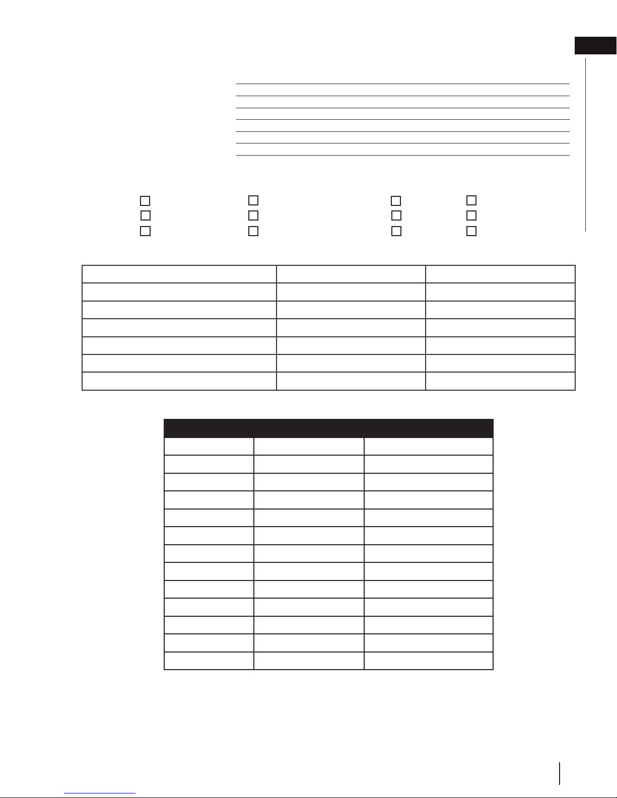
standard checklist
EN
Natural Gas: BHD4PN BHD4STN
BHD4PGN BHD4STGN
BHD4PFCN BHD4STFCN
Fuel Type Natural Gas Propane
Altitude (FT) 0-4,500 0-4,500
Max. Input (BTU/hr) 30,000 30,000
Max. Output (BTU/hr) 23,000 23,000
Min. Inlet Gas Supply Pressure 4.5” w.c. (11mb) 11” w.c. (27mb)
Max. Inlet Gas Supply Pressure 13” w.c. (32mb) 13” w.c. (32mb)
Manifold Pressure (Under Flow Confictions) 3.5” w.c. (9mb) 10” w.c. (25mb)
Product Codes
Media type Fuel type
BHD4PN
BHD4PP
Logs Natural Gas
Logs Propane
Propane: BHD4PP BHD4STP
BHD4PGP BHD4STGP
BHD4PFCP BHD4STFCP
BHD4STN
BHD4STP
BHD4PGN
BHD4PGP
BHD4STGN
BHD4STGP
BHD4PFCN
BHD4PFCP
BHD4STFCN
BHD4STFCP
Logs Natural Gas
Logs Propane
Glass Natural Gas
Glass Propane
Glass Natural Gas
Glass Propane
Fire Cradle Natural Gas
Fire Cradle Propane
Fire Cradle Natural Gas
Fire Cradle Propane
W415-1285 / G / 04.27.18
5
Page 6
EN
general information
1.0 general information
When the appliance is installed at elevations above 4,500ft (1372m), and in the absence of specific recommendations
from the local authority having jurisdiction, the certified high altitude input rating shall be reduced at the rate of 4% for each
additional 1,000ft (305m). Expansion / contraction noises during heating up and cooling down cycles are normal
and are to be expected. Change in flame appearance from “HI” to “LO” is more evident in natural gas than in
propane.
This appliance is approved for bathroom, bedroom and bed-sitting room installations and is certified for mobile
home installation.
This appliance is only for use with the type of gas indicated on the rating plate. This appliance is not
convertible for use with other gases, unless a certified kit is used.
note:
A barrier designed to reduce the risk of burns from the hot viewing glass is provided with the
appliance and must be installed.
The protective wrap on plated parts is best removed when the assembly is at room temperature but this can be
improved if the assembly is warmed, using a hair dryer or similar heat source.
This appliance is a decorative product. It is not a source of heat and not intended to burn solid fuel.
No external electricity (110 volts or 240 volts) is required for the gas system operation. If utilizing one
of Wolf Steel's trim or surround kits, follow the framing instructions and the finishing instructions for
removal of the top extension.
Batteries must be disposed of according to the local laws and regulations. Some batteries may be
recycled, and may be accepted for disposal at your local recycling center. Check with your
municipality for recycling instructions.
6
W415-1285 / G / 04.27.18
Page 7
general information
to conform with local
roof joist. If the appliance is installed directly on carpeting, vinyl tile or other combustible material other than wood fl ooring, the
WARNING
!
• Always light the pilot whether for the first time or if the gas supply has run out, with the glass door opened
or removed.
• Provide adequate clearance for servicing and operating the appliance.
• Provide adequate ventilation.
• Never obstruct the front opening of the appliance.
• Objects placed in front of the appliance must be kept a minimum of 48” (121.9cm) from the front face of
the appliance.
• Surfaces around and especially above the appliance can become hot. Avoid contact when appliance is
operating.
• Fire risk. Explosion hazard.
• High pressure will damage valve. Disconnect gas supply piping before pressure testing gas line at test
pressures above 1/2 PISG (35mb). Close the manual shut-off valve before pressure testing gas line at test
pressures equal to or less than 1/2 PISG (35mb).
• Use only Wolf Steel approved optional accessories and replacement parts with this appliance using nonlisted accessories (blowers, doors, louvres, trims, gas components, venting components, etc.) could result
in a safety hazard and will void the warranty and certification.
• The appliance must not be operated at temperatures below freezing (32ºF/0ºC). Allow the appliance to
warm to above freezing prior to operation.
EN
THIS GAS APPLIANCE MUST BE INSTALLED AND SERVICED BY A QUALIFIED INSTALLER
codes. Installation practices vary from region to region and it is important to know the specifi cs that apply to your area, for
example in the state of Massachusetts:
• This product must be installed by a licensed plumber or gas fi tter when installed within the commonwealth of
Massachusetts.
• The appliance damper must be removed or welded in the open position prior to installation of an appliance insert or gas
log.
• The appliance off valve must be a “T” handle gas cock.
• The fl exible connector must not be longer than 36 inches (0.9m).
• A carbon monoxide detector is required in all rooms containing gas fi red appliances.
• The appliance is not approved for installation in a bedroom or bathroom unless the unit is a direct vent sealed
combustion product.
The installation must conform with local codes or, in absence of local
codes, the National Gas and Propane Installation Code CSA B149.1
in Canada, or the National Fuel Gas Code, ANSI Z223.1 / NFPA 54
in the United States. Suitable for mobile home installation if installed
in accordance with the current standard CAN/CSA Z240MH Series,
for gas equipped mobile homes, in Canada or ANSI Z223.1 and
NFPA 54 in the United States.
The appliance and its individual shutoff valve must be disconnected
from the gas supply piping system during any pressure testing
of that system at test pressures in excess of 1/2 psig (35 mb).
The appliance must be isolated from the gas supply piping system by closing its individual manual shutoff valve during any
pressure testing of the gas supply piping system at test pressures equal to or less than 1/2 psig (35 mb). When installed
with a blower or fan, the junction box must be electrically connected and grounded in accordance with local codes. In the
absence of local codes, use the current CSA C22.1 Canadian Electrical Code in Canada or the ANSI / NFPA 70 National
Electric Code in the United States. In the case where the blower is equipped with a power cord, it must be connected into a
properly grounded receptacle. The grounding prong must not be removed from the cord plug.
The following does not apply to inserts; as long as the required clearance to combustibles is maintained, the most desirable
and benefi cial location for an appliance is in the center of a building, thereby allowing the most effi cient use of the heat
created. The location of windows, doors and, the traffi c fl ow in the room where the appliance is to be located should be
considered. If possible, you should choose a location where the vent will pass through the house without cutting a fl oor or
www.ncertied.org
We suggest that our gas
hearth products be installed
and serviced by professionals
who are certied in the U.S.
by the National Fireplace
®
Institute
(NFI) as NFI Gas
Specialists
appliance shall be installed on a metal or wood panel extending the full width and depth, unless otherwise tested.
W415-1285 / G / 04.27.18
7
Page 8
EN
CÔTÉS 0”
SAMPLE
To convert from one gas to another, consult your Authorized dealer/distributor.
general information
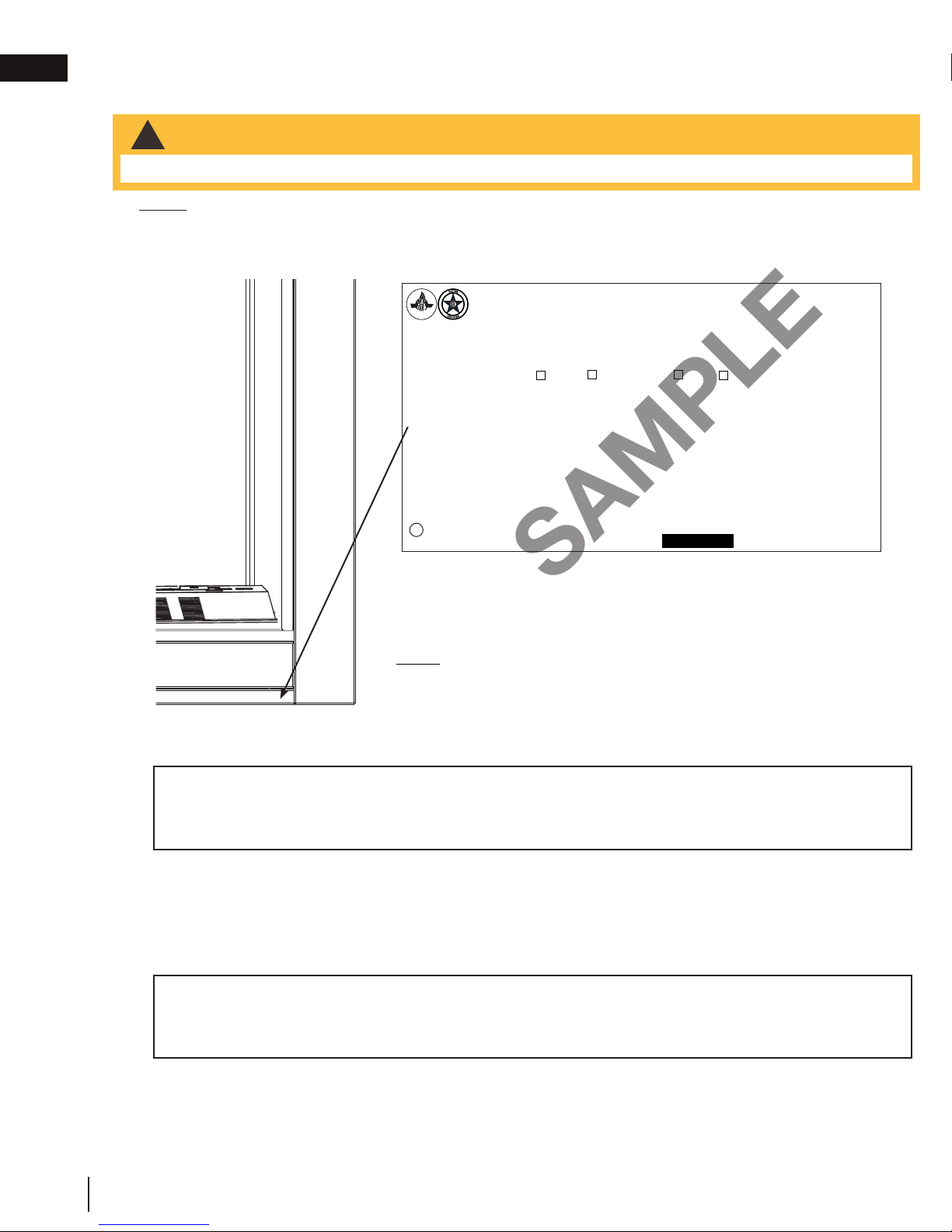
1.1 rating plate / lighting instruction location
WARNING
!
• Allow the appliance to cool before performing any maintenance or cleaning.
NOTE: Screen must be removed to access rating plate / lighting instructions.
Both the rating plate and lighting instructions are attached to a cable and located behind the control panel of the
appliance. Lift the access plate and control panel up and away from the appliance. With the cable at the bulb end of
the slot, wiggle the rating plate out being careful not to tear the instructions.
CONFORMS TO / CONFORME AUX: ANSI Z21.50 - 2016, CERTIFIED TO / CERTIFIÉ CSA 2.22 - 2016 VENTED DECORATIVE GAS APPLIANCE / FOYER À GAZ VENTILÉ
VENTED GAS FIREPLACE. APPROVED FOR BEDROOM, BATHROOM AND BED-SITTING ROOM INSTALLATION. SUITABLE FOR MOBILE HOME INSTALLATION IF INSTALLED IN ACCORDANCE WITH THE CURRENT
STANDARD CAN/CSA Z240MH SERIES GAS EQUIPPED MOBILE HOMES, IN CANADA OR IN THE UNITED STATES THE MANUFACTURED HOME CONSTRUCTION AND SAFETY STANDARD, TITLE 24 CFR, PART
CERTI FIED
CERTIFIED FOR / CERTIFIEE
POUR CANADA / USA
REFERENCE # 161746
THIS VENTED GAS FIREPLACE IS
NOT FOR USE WITH AIR FILTERS.
NOT FOR USE WITH SOLID FUEL.
FOR USE WITH GLASS DOORS
CERTIFIED WITH THIS APPLIANCE
ONLY.
WARNING: DO NOT ADD ANY MATERIAL
TO THE APPLIANCE, WHICH WILL COME IN
CONTACT WITH THE FLAMES, OTHER THAN
THAT SUPPLIED BY THE MANUFACTURER
WITH THE APPLIANCE.
DECORATIVE PRODUCT: NOT FOR USE AS A
HEATING APPLIANCE
MINIMUM CLEARANCE TO
COMBUSTIBLE MATERIALS:
TOP 0”
FLOOR 0”
SIDES 0”
BACK 0”
VENT TOP 3”
VENT SIDES & BOTTOM 2”
VERTICAL VENT 1”
MANTEL 8”*
TOP SIDES & BACK: PER STAND OFF SPACERS FOR FRAMING
MATERIALS. FOR FINISHING MATERIALS, SEE OWNER’S MANUAL
*MAXIMUM HORIZONTAL EXTENSION / L’EXTENSION HORIZONTALE
MAXIMALE: 2”. SEE INSTRUCTION MANUAL FOR GREATER EXTENSIONS.
SEE OWNER’S INSTRUCTION MANUAL FOR MINIMUM AND MAXIMUM LENGTHS.
3280. WHEN THIS US STANDARD IS NOT APPLICABLE USE THE STANDARD FOR FIRE SAFETY CRITERIA FOR MANUFACTURED HOME INSTALLATIONS, SITES AND COMMUNITIES, ANSI/NFPA 501A. FOYER À
GAZ VENTILÉ. HOMOLOGUÉ POUR INSTALLATION DANS UNE CHAMBRE À COUCHER, UNE SALLE DE BAIN ET UN STUDIO. APPROPRIÉ POUR INSTALLATION DANS UNE MAISON MOBILE SI SON INSTALLATION
CONFORME AUX EXIGENCES DE LA NORME CAN/CSA Z240MH SÉRIE DE MAISONS MOBILES ÉQUIPÉES AU GAZ EN VIGEUR AU CANADA OU AUX ÉTATS-UNIS DE LA NORME DE SÉCURITÉ ET DE CONSTRUCTION DE MAISONS MANUFACTURÉE, TITRE 24 CFR, SECTION 3280. DANS LE CAS OU CETTE NORME D’ÉTATS-UNIS NE PEUT ÊTRE APPLIQUÉE, SE RÉFÉRER A LA NORME RELATIVE AU CRITÈRE DE
MESURES DE SÉCURITÉ CONTRE L’INCENDIE POUR LES INSTALLATIONS DANS LES MAISONS MANUFACTURÉS, LES SITES ET LES COMMUNAUTÉS, ANSI/NFPA 501A. THIS APPLIANCE MUST BE INSTALLED IN
ACCORDANCE WITH LOCAL CODES, IF ANY; IF NONE, FOLLOW THE CURRENT ANSI Z223.1 OR CSA B149, INSTALLATION CODES. INSTALLER L’APPAREIL SELON LES CODES D’INSTALLATION ANSI Z223.1 OU
CSA-B149 EN VIGUER.
MODEL NATURAL GAS /
GAZ NATUREL
0-4500FT (0-1370M) ALTITUDE / ÉLÉVATION 0-4500FT (0-1370M)
30,000 BTU/H
23,000 BTU/H REDUCED INPUT / ALIMENTATION RÉDUITE 23,000 BTU/H
3.5” WATER COLUMN/D’UNE COLONNE D’EAU
PRESSION AU COLLECTEUR
4.5“ WATER COLUMN/D’UNE COLONNE D’EAU MINIMUM SUPPLY PRESSURE / 11” WATER COLUMN/D’UNE COLONNE D’EAU
7.0“ WATER COLUMN/D’UNE COLONNE D’EAU MAXIMUM SUPPLY PRESSURE 13” WATER COLUMN/D’UNE COLONNE D’EAU
67.9% P.4 67.9%
ELECTRICAL RATING: 115V.60HZ. LESS THAN 12 AMPERES
WOLF STEEL LTD.
24 NAPOLEON ROAD, BARRIE, ON, L4M 0G8 CANADA
BHD4N BHD4P
THE APPLIANCE MUST BE VENTED USING THE APPROPRIATE
NAPOLEON VENT KITS. SEE OWNERS INSTALLATION MANUAL
FOR VENTING SPECIFICS. PROPER REINSTALLATION AND
RESEALING IS NECESSARY AFTER SERVICING THE VENT-AIR
SERIAL NUMBER/ NO. DE SÉRIE: BHD4
MODEL PROPANE /
CBHD4N CBHD4P
INPUT / ALIMENTATION 30,000 BTU/H
MANIFOLD PRESSURE / 10” WATER COLUMN/D’UNE COLONNE D’EAU
PRESSION D’ALIMENTATION MINIMALE
PRESSION D’ALIMENTATION MAXIMALE
INTAKE SYSTEM.
PROPANE MODÈLE
L’APPAREIL DOIT ÉVACUER SES GAZ EN UTILISANT
L’ENSEMBLE D’ÉVACUATION PROPRE À NAPOLEON. RÉFÉRER
AU MANUEL D’INSTALLATION DE PROPRIÉTAIRE POUR
L’ÉVACUATION PRÉCISE. IL EST IMPORTANT DE BIEN
RÉINSTALLER ET RESCELLER L’ÉVENT APRÉS AVOIR ASSURÉ
LE MAINTIEN DU SYSTÉME DE PRISE D’AIR.
DESSUS, CÔTÉS & ARRIÈRE : SELON LES ESPACEURS DE
DÉGAGEMENT POUR LES MATÉRIAUX D’OSSATURE SELON
LA MANUEL DE PROPRIÉTAIRE POUR LES MATÉRIAUX DE
FINITION. *L’EXTENSION HORIZONTALE MAXIMALE : 2”.
RÉFÉRER AU MANUAL D’INSTRUCTION POUR DES
EXTENSIONS PLUS GRANDES. RÉFÉRER AU MANUEL
D’INSTALLATION DE PROPRIÉTAIRE.
SPÉCIFICATIONS ÉLECTRIQUES : 115 V,
60HZ. MOINS DE 12 AMPÈRES.
CET FOYER À GAZ VENTILÉ N'EST
PAS POUR L'USAGE AVEC LES
FILTRES D'AIR.
UN COMBUSTIBLE SOLIDE NE PAS
ÊTRÉ UTILISÉ AVEC CET APPAREIL.
UTILISER AVEC LES PORTE VITRÉES
HOMOLOGUÉES SEULEMENT AVEC
CETTE APPAREIL.
ADVERTISSEMENT : N’AJOUTEZ PAS À
CET APPAREIL AUCUN MATÉRIAU DEVANT
ENTRER EN CONTACT AVEC LES FLAMMES
AUTRE QUE CELUI QUI EST FOURNI AVECT CET
APPAREIL PAR LE FABRICANT.
PRODUIT DÉCORATIF: NE PAS UTILISER COMME
APPAREIL DE CHAUFFAGE
DÉGAGEMENTS MINIMAUX DES MATÉRIAUX
COMBUSTIBLES :
DESSUS 0”
PLANCHER 0”
ARRIÈRE 0”
DESSUS DU CONDUIT D’EVENT 3”
CÔTÉS ET DESSOUS DU CONDUIT
D’EVENT 2”
CONDUIT D’EVENT VERTICAL 1”
TABLETTE 8”*
W385-1936 / A
This illustration is for reference only. Refer to the rating plate on the appliance for accurate information.
NOTE : The rating plate must remain with the appliance at all times. It
must not be removed.
1.2 mobile home installation
This appliance must be installed in accordance with the manufacturer’s instructions and the Manufactured
Home Construction and Safety Standard, Title 24 CFR, Part 3280, in the United States or the Mobile Home
Standard, CAN/CSA Z240 MH Series, in Canada. This appliance is only for use with the type(s) of gas
indicated on the rating plate.
This mobile/manufactured home listed appliance comes factory equipped with a means to secure the appliance. Built
in appliances are equipped with 1/4” (6.4mm) diameter holes located in the front left and right corners of the base.
Use appropriate fasteners, inserted through the holes in the base to secure. For free standing products contact your
local authorized dealer / distributor for the appropriate securing kit. For mobile home installations, the appliance must
be fastened in place. It is recommended that the appliance be secured in all installations. Always turn off the pilot and
the fuel supply at the source, prior to moving the mobile home. After moving the mobile home and prior to lighting the
appliance, ensure that the logs are positioned correctly.
This appliance is certifi ed to be installed in an aftermarket permanently located, manufactured (mobile) home,
where not prohibited by local codes.
This appliance is only for use with the type of gas indicated on the rating plate. This appliance is not convertible
for use with other gases, unless a certifi ed kit is used.
Conversion Kits
This appliance is fi eld convertible between Natural Gas (NG) and Propane (P).
8
W415-1285 / G / 04.27.18
Page 9
general information
8"
203mm
5"
127mm
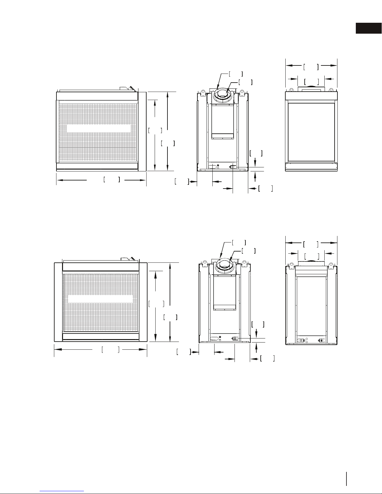
2.0 dimensions
25 1/8"
638mm
12 13/16"
325mm
EN
SAFETY BARRIER
43 1/4"
BHD4P ILLUSTRATED
SAFETY BARRIER
1099mm
34 3/16"
868mm
38 1/4"
841mm
34 3/16"
868mm
7 9/16"
192mm
GAS
38 1/4"
841mm
INLET
8"
203mm
127mm
2 1/16"
53mm
7 9/16"
192mm
ELECTRICAL INLET
5"
2 1/16"
53mm
RIGHT
SIDE
RIGHT
SIDE
LEFT
SIDE
25 1/8"
638mm
12 13/16"
325mm
LEFT
SIDE
45"
1143mm
BHD4ST ILLUSTRATED
7 9/16"
192mm
GAS INLET
7 9/16"
192mm
ELECTRICAL INLET
W415-1285 / G / 04.27.18
9
Page 10
EN
WARNING
!
WARNING
• Risk of fi re. Maintain specifi ed air space clearances to vent pipe and appliance.
• The vent system must be supported every 3’(0.9m) for both vertical and horizontal runs. Use support ring
assembly W010-0067 or equivalent non-combustible strapping to maintain the minimum clearance to
combustibles for both vertical and horizontal runs. Spacers are attached to the inner pipe at predetermined
intervals to maintain an even air gap to the outer pipe. This gap is required for safe operation. A spacer is
required at the start, middle, and end of each elbow to ensure this gap is maintained. These spaces must
not be removed.
This appliance uses a 5” (127mm) exhaust / 8” (203.2mm) air intake vent pipe system. Refer to the
section applicable to your installation.
For safe and proper operation of the appliance follow the venting instructions exactly. Deviation from the
minimum vertical vent length can create diffi culty in burner start-up and/or carboning. Under extreme vent
confi gurations, allow several minutes (5-15) for the fl ame to stabilize after ignition. Although not a requirement,
it is recommended for vent lengths that pass through unheated spaces (attics, garages, crawl spaces) be
insulated with the insulation wrapped in a protective sleeve to minimize condensation. Provide a means for
visually checking the vent connection to the appliance after the appliance is installed. Use a fi restop, vent pipe
shield or attic insulation shield when penetrating interior walls, fl oor or ceiling.
The vent terminal may be painted with a high temperature paint to match exterior colours. Use an outdoor paint
suitable for 400°F (200°C). Application and performance of paint is the consumer’s responsibility. Spot testing is
recommended.
a minimum.
If for any reason the vent air intake system is disassembled; reinstall per the instructions provided for the
initial installation.
This appliance must be installed with a continuous connection of exhaust and air intake vent pipes. Utilizing
alternate constructions, such as a chimney as part of the vent system, is not permitted.
note:
When using Wolf Steel venting components, use only approved Wolf Steel rigid / fl exible components with the
GD420 or the 10 foot (3.1m) vent kit GD430.
3.0 venting requirements
venting requirements
!
• Risk of fi re. Maintain specifi ed air space clearances to vent pipe and appliance.
• The vent system must be supported every 3’(0.9m) for both vertical and horizontal runs. Use support ring
assembly W010-0067 or equivalent non-combustible strapping to maintain the minimum clearance to
combustibles for both vertical and horizontal runs. Spacers are attached to the inner pipe at predetermined
intervals to maintain an even air gap to the outer pipe. This gap is required for safe operation. A spacer is
required at the start, middle, and end of each elbow to ensure this gap is maintained. These spaces must
not be removed.
This appliance uses a 5” (127mm) exhaust / 8” (203.2mm) air intake vent pipe system. Refer to the
section applicable to your installation.
For safe and proper operation of the appliance follow the venting instructions exactly. Deviation from the
minimum vertical vent length can create diffi culty in burner start-up and/or carboning. Under extreme vent
confi gurations, allow several minutes (5-15) for the fl ame to stabilize after ignition. Although not a requirement,
it is recommended for vent lengths that pass through unheated spaces (attics, garages, crawl spaces) be
insulated with the insulation wrapped in a protective sleeve to minimize condensation. Provide a means for
visually checking the vent connection to the appliance after the appliance is installed. Use a fi restop, vent pipe
shield or attic insulation shield when penetrating interior walls, fl oor or ceiling.
The vent terminal may be painted with a high temperature paint to match exterior colours. Use an outdoor paint
suitable for 400°F (200°C). Application and performance of paint is the consumer’s responsibility. Spot testing is
recommended.
note:
If for any reason the vent air intake system is disassembled; reinstall per the instructions provided for the
initial installation.
This appliance must be installed with a continuous connection of exhaust and air intake vent pipes. Utilizing
alternate constructions, such as a chimney as part of the vent system, is not permitted.
You may reduce the appliance from 5/8" venting to 4/7" venting for horizontal and vertical rise applications.
Reducing must be done right off of the appliance and a new firestop spacer (W010-3440) will be required.
Use only Wolf Steel, Simpson Dura-Vent, Selkirk Direct Temp, American Metal Amerivent or Metal-Fab venting
components. Minimum and maximum vent lengths, for both horizontal and vertical installations, clearances from
vent pipes to combustibles and air terminal locations as set out in this manual apply to all vent systems and
must be adhered to. For Simpson Dura-Vent, Selkirk Direct Temp, American Metal Amerivent and Metal-Fab,
follow the installation procedure provided with the venting components. A starter adaptor must be used with the
following vent systems and may be purchased from the corresponding supplier:
Vent
Manufacturer
Duravent W175-0170 Wolf Steel www.duravent.com
Amerivent 5DSC-N2 American Metal www.americanmetalproducts.com
Direct Temp 5DT-AA Selkirk www.selkirkcorp.com
SuperSeal 5DNA Metal-Fab www.mtlfab.com
For vent systems that provide seals on the inner exhaust fl ue, only the outer air intake joints must be sealed using
a red high temperature silicone (RTV). This same sealant may be used on both the inner exhaust and outer intake
vent pipe joints of all other approved vent systems except for the exhaust vent pipe connection to the appliance
fl ue collar which must be sealed using the black high temperature sealant Mill Pac.
following termination kits: wall terminal kit GD422R-2, or 1/12 to 7/12 pitch roof terminal kit GD410, 8/12 to
This template must be used in conjunction with templates 7.2.1 or 7.2.2, depending on termina-
12/12 roof terminal kit GD411, fl at roof terminal kit GD412 or periscope kit GD401 (for wall penetration below
tion shape (i.e. round, or round and square). See appropriate templates folder.
grade). With fl exible venting, in conjunction with the various terminations, use either the 5 foot (1.5m) vent kit
For optimum fl ame appearance and appliance performance, keep the vent length and number of elbows to
10
W415-1285 / G / 04.27.18
Starter Adapter Part
Number
W175-0053
4DSC-N2
4DT-AAN
4DNA
Supplier Website
Page 11

• The vent system must be supported every 3’(0.9m) for both vertical and horizontal runs. Use support ring
assembly W010-0067 or equivalent non-combustible strapping to maintain the minimum clearance to
combustibles for both vertical and horizontal runs. Spacers are attached to the inner pipe at predetermined
intervals to maintain an even air gap to the outer pipe. This gap is required for safe operation. A spacer is
required at the start, middle, and end of each elbow to ensure this gap is maintained. These spaces must
not be removed.
This appliance uses a 5” (127mm) exhaust / 8” (203.2mm) air intake vent pipe system. Refer to the
section applicable to your installation.
For safe and proper operation of the appliance follow the venting instructions exactly. Deviation from the
minimum vertical vent length can create diffi culty in burner start-up and/or carboning. Under extreme vent
confi gurations, allow several minutes (5-15) for the fl ame to stabilize after ignition. Although not a requirement,
it is recommended for vent lengths that pass through unheated spaces (attics, garages, crawl spaces) be
insulated with the insulation wrapped in a protective sleeve to minimize condensation. Provide a means for
visually checking the vent connection to the appliance after the appliance is installed. Use a fi restop, vent pipe
shield or attic insulation shield when penetrating interior walls, fl oor or ceiling.
The vent terminal may be painted with a high temperature paint to match exterior colours. Use an outdoor paint
suitable for 400°F (200°C). Application and performance of paint is the consumer’s responsibility. Spot testing is
recommended.
For vent systems that provide seals on the inner exhaust fl ue, only the outer air intake joints must be sealed using
a red high temperature silicone (RTV). This same sealant may be used on both the inner exhaust and outer intake
vent pipe joints of all other approved vent systems except for the exhaust vent pipe connection to the appliance
fl ue collar which must be sealed using the black high temperature sealant Mill Pac.
For optimum fl ame appearance and appliance performance, keep the vent length and number of elbows to
(31.8mm) air gap all around between the inner liner and outer liner is required for safe operation.
Vent
Manufacturer
Starter Adapter Part
Number
Supplier Website
Duravent W175-0170 Wolf Steel www.duravent.com
Amerivent 5DSC-N2 American Metal www.americanmetalproducts.com
Direct Temp 5DT-AA Selkirk www.selkirkcorp.com
SuperSeal 5DNA Metal-Fab www.mtlfab.com
Use only Wolf Steel, Simpson Dura-Vent, Selkirk Direct Temp, American Metal Amerivent or Metal-Fab venting
components. Minimum and maximum vent lengths, for both horizontal and vertical installations, clearances from
vent pipes to combustibles and air terminal locations as set out in this manual apply to all vent systems and
must be adhered to. For Simpson Dura-Vent, Selkirk Direct Temp, American Metal Amerivent and Metal-Fab,
follow the installation procedure provided with the venting components. A starter adaptor must be used with the
following vent systems and may be purchased from the corresponding supplier:
If for any reason the vent air intake system is disassembled; reinstall per the instructions provided for the
initial installation.
This appliance must be installed with a continuous connection of exhaust and air intake vent pipes. Utilizing
alternate constructions, such as a chimney as part of the vent system, is not permitted.
note:
This template must be used in conjunction with templates 7.2.1 or 7.2.2, depending on termina-
tion shape (i.e. round, or round and square). See appropriate templates folder.
venting requirements
EN
a minimum.
The air terminal must remain unobstructed at all times. Examine the air terminal at least once a year
to verify that it is unobstructed and undamaged.
Rigid and fl exible venting systems must not be combined. Different venting manufacturer components
must not be combined.
These vent kits allow for either horizontal or vertical venting of the appliance. The maximum allowable horizontal
run is 20 feet (6.1m). The maximum allowable vertical vent length is 40 feet (12.2m). The maximum number of
vent connections is two horizontally or three vertically (excluding the appliance and the air terminal connections)
when using fl exible venting.
Horizontal runs may have a 0” (0mm) rise per foot/meter however for optimum performance it is recommended
that all horizontal runs have a minimum 1/4” (21mm) rise per foot/meter using fl exible venting. For safe and
proper operation of the appliance, follow the venting instructions exactly.
A terminal shall not terminate directly above a sidewalk or paved driveway which is located between two single
family dwellings and serves both dwellings. Local codes or regulations may require different clearances.
Do not allow the inside liner to bunch up on horizontal or vertical runs and elbows. Keep it pulled tight. A 1¼”
FOR 4” / 7” (USE REDUCER KIT A4758AK TO TRANSITION FROM 5” / 8” TO 4” /7” VENTING)
When using Wolf Steel 4"/7" venting components, use only approved Wolf Steel rigid / flexible components with the following
termination kits: wall terminal kit GD222R, or 1/12 to 7/12 pitch roof terminal kit GD110, 8/12 to 12/12 roof terminal kit GD111,
flat roof terminal kit GD112 or periscope kit GD201 (for wall penetration below grade). With flexible venting, in conjunction with the
various terminations, use either the 5 foot (1.5m) vent kit GD220 or the 10 foot (3.1m) vent kit GD330.
When using Wolf Steel 5"/8" venting components, use only approved Wolf Steel rigid / flexible components with the following
termination kits: wall terminal kit GD422R-1, or 1/12 to 7/12 pitch roof terminal kit GD410, 8/12 to 12/12 roof terminal
kit GD411, flat roof terminal kit GD412 or periscope kit GD401 (for wall penetration below grade). With flexible venting, in
conjunction with the various terminations, use either the 5 foot (1.5m) vent kit GD420 or the 10 foot (3.1m) vent kit GD430.
W415-1285 / G / 04.27.18
11
Page 12

EN
venting requirements
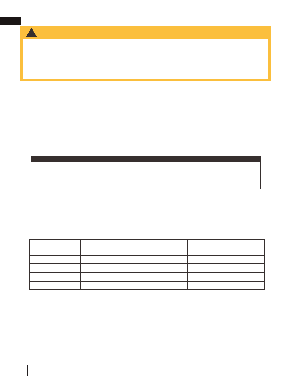
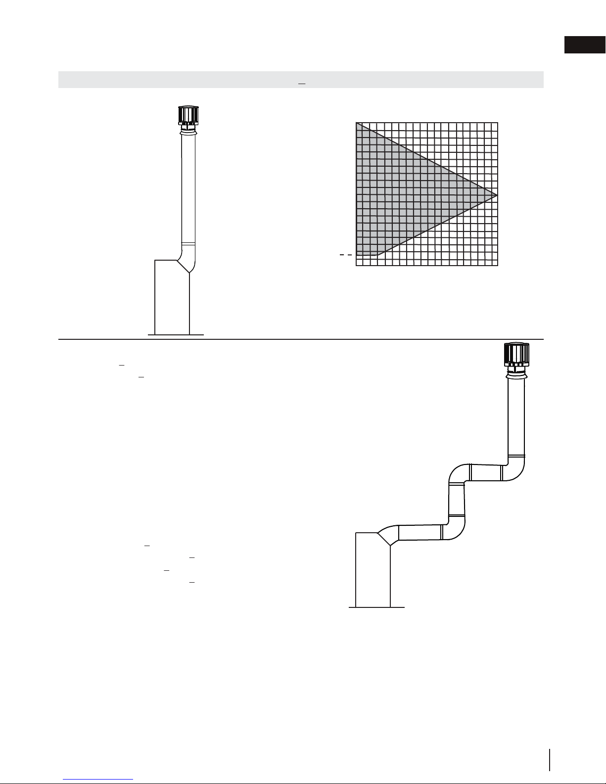
3.1 typical vent installations
16" MIN (40.6cm)
24" (61cm)
MAX
43" (109.2cm)
MIN PLUS
RISE*
When venting, the horizontal run must be kept to a
maximum of 20 feet (6m). If a 20 foot (6m) horizontal
run is required, the appliance must have a minimum
vertical rise off the appliance of 57" (144.8cm).
40 FT
(12m)
MAX
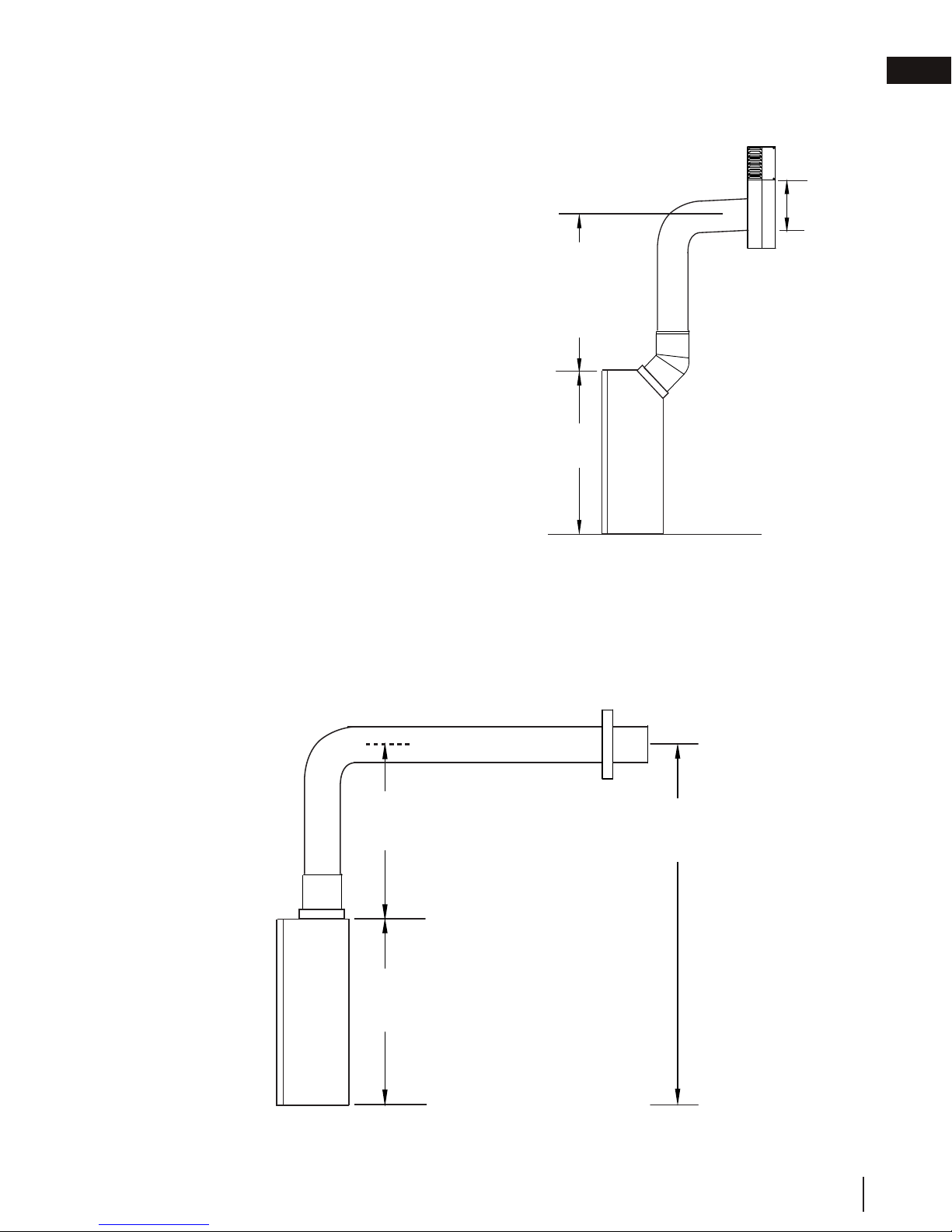
36"
(91.4cm)
MIN
38 1/4"
(97.2cm)
When terminating vertically, the vertical rise is a
minimum 36" (91.4cm) and a maximum 40 feet (12m)
above the appliance.
On all horizontal vent runs, ensure that the vent pipe does not slope downward.
* See "venting" section.
12
W415-1285 / G / 04.27.18
Page 13
venting requirements
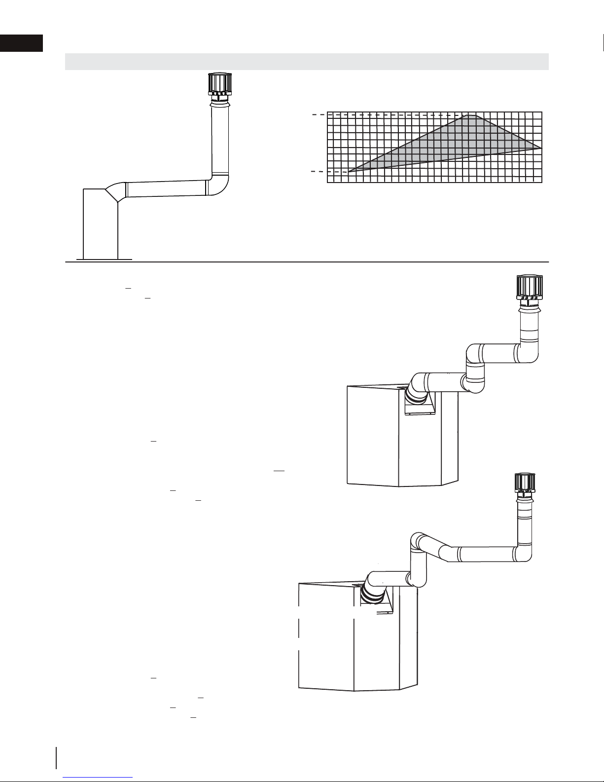
3.2 special vent installations
3.2.1 periscope termination
Use the periscope kit to locate the air termination above grade. The periscope must
be installed so that when fi nal grading is completed, the bottom air slot is located a
minimum of 12” (305mm) above grade. The maximum allowable vent length is
10’ (3.1m) for a fi replace and 8’ (2.4m) for a stove.
24" (61cm) MIN
REGARDLESS OF
HORIZONTAL VENT
LENGTH
38 1/4"
(97.2cm)
EN
12"
(30.5cm)
MIN TO
GRADE
3.2.2 reduced vent clearance to combustibles
The minimum clearances around the horizontal vent pipe to the combustible material may be reduced from
3" (76.2mm) / 2" (50.8mm) to 1" (25.4mm) in installations with a minimum of 52" (132cm) vertical rise made
immediately off the appliance collar and where the vent has been reduced to a 4/7" from 5/8" at the appliance.
52"
(132cm)
38 1/4"
(97.2cm)
90 1/4"
(229.2cm)
W415-1285 / G / 04.27.18
13
Page 14
EN
venting requirements
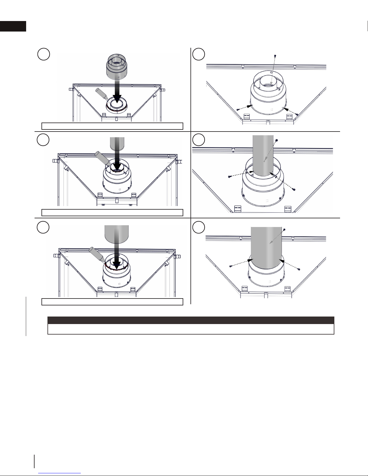
3.3 converting from 5/8" to 4/7" venting
1 2
Use Mill Pac to seal adapter to the appliance collars.
3
Ue Mill Pac to seal adapter to the appliance collars.
5 6
X3
4
X3
X3
Use red RTV silicone sealant to seal adapter to the appliance collars.
note:
Depending on your adaptor kit, the 4/7" venting components may not come pre-assembled.
14
W415-1285 / G / 04.27.18
Page 15
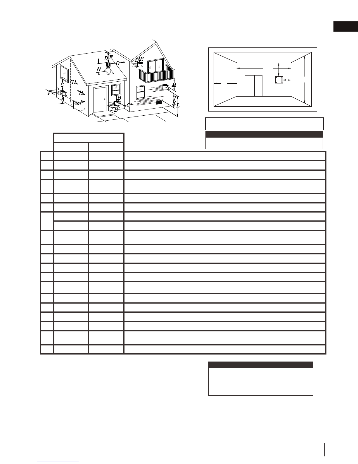
3.4 vent terminal clearances
Covered balcony applications
††* Permitted only if the balcony is fully open on a minimum of one side.
venting requirements
R
EN
††*
Q
S
P
G
Q
= 3 feet
MIN
(0.9m)
INSTALLATIONS
CANADA U.S.A.
12” (30.5cm) 12” (30.5cm) Clearance above grade, veranda porch, deck or balcony.
A
Δ
12” (30.5cm)
B
12” (30.5cm)* 12” (30.5cm)* Clearance to permanently closed windows.
C
D
E
F
G
H
I
J
K
L
M
18”
(45.7cm)**
12” (30.5cm)** 12” (30.5cm)** Clearance to unventilated soffi t.
0” (0mm) 0” (0mm) Clearance to an outside corner wall.
0” (0mm)*** 0” (0mm)***
2” (51mm)*** 2” (51mm)*** Clearance to an inside combustible corner wall or protruding combustible obstructions (vent chase, etc.).
3’(0.9m) 3’(0.9m)****
3’ (0.9m) 3’ (0.9m)**** Clearance to a service regulator vent outlet.
12” (30.5cm) 9” (229mm) Clearance to a non-mechanical air supply inlet to the building or a combustion air inlet to any other appliance.
6’ (1.8m) 3’ (0.9m) † Clearance to a mechanical air supply inlet.
7’ (2.1m) ‡ 7’ (2.1m) **** Clearance above a paved sidewalk or paved driveway located on public property.
12” (30.5cm)†† 12” (30.5cm)**** Clearance under a veranda, porch or deck.
9” (229mm) ΔClearance to windows or doors that open.
18”
(45.7cm)**
Vertical clearance to ventilated soffi ts located above the terminal within a horizontal distance of 2’
(0.6m) from the center line of the terminal.
Clearance to an inside non-combustible corner wall or protruding non-combustible obstructions (chimney, etc.).
Clearance to each side of the center line extended above the meter / regulator assembly to a maximum vertical distance of 15’ (4.6m).
note:
Wall terminals are for illustration purposes only. Size and
shapes may vary.
R
= 2 x
MAX
Q
ACTUAL
R
MAX
≤ 15 feet
(4.6m)
16” (40.6cm) 16” (40.6cm) Clearance above the roof.
N
2’ (0.6m)†* 2’ (0.6m) †* Clearance from an adjacent wall including neighbouring buildings.
O
8’ (2.4m) 8’ (2.4m)
P
3’ (0.9m) 3’ (0.9m) See chart for wider wall dimensions.
Q
6’ (1.8m) 6’ (1.8m)
R
12” (30.5cm) 12” (30.5cm) Clearance under a covered balcony
S
Δ The terminal shall not be located less than 6 feet under a window that opens on a horizontal plane in a structure with three walls and a roof.
* Recommended to prevent condensation on windows and thermal breakage
** It is recommended to use a heat shield and to maximize the distance to vinyl clad soffi ts.
*** The periscope requires a minimum 18 inches clearance from an inside corner.
**** This is a recommended distance. For additional requirements, check local codes.
† 3 feet above if within 10 feet horizontally.
‡ A vent shall not terminate where it may cause hazardous frost or ice accumulations on adjacent property surfaces.
†† Permitted only if the veranda, porch, or deck is fully open on a minimum of two sides beneath the fl oor.
†* Recommended to prevent recirculation of exhaust products. For additional requirements, check local codes.
Roof must be non-combustible without openings.
See chart for deeper wall dimensions. The terminal shall not be installed on any wall that has an
opening between the terminal and the open side of the structure.
note:
Clearances are to be in accordance with local
installation codes and the requirements of the gas
supplier. In their absence, clearances are to be as
listed above and are based on national codes.
W415-1285 / G / 04.27.18
15
Page 16
EN
venting requirements
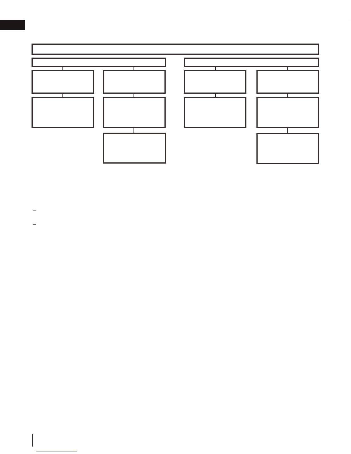
3.5 vent application flow chart
Top Exit
Horizontal Termination
Vertical rise is equal
to or greater than the
horizontal run
Horizontal run +
vertical rise to
maximum of
40 feet (12.2m)
Vertical rise is less
than horizontal run
Horizontal run +
vertical rise to
maximum of
24.75 feet (7.5m)
4.2 times the vertical
rise equal to or
greater than the
horizontal run
3.6 definitions
For the following symbols used in the venting calculations and
examples are:
> - greater than
> - equal to or greater than
< - less than
< - equal to or less than
HT - total of both horizontal vent lengths (Hr) and offsets (Ho) in feet
HR - combined horizontal vent lengths in feet
HO - offset factor: .03 (total degrees of offset - 90°*) in feet
HO - offset factor: .03 (total degrees of offset - 135°*) in feet
VT - combined vertical vent lengths in feet
Vertical Termination
Vertical rise is equal
to or greater than the
horizontal run
Horizontal run +
vertical rise to
maximum of
40 feet (12.2m)
Vertical rise is less
than horizontal run
Horizontal run +
vertical rise to
maximum of
19 (5.8m)
3 times the vertical
rise equal to or
greater than the
horizontal run
3.7 elbow vent length values
Feet Inches Millimeters
1° 0.03 0.5 12.7
15° 0.45 6.0 152.4
30° 0.9 11.0 279.4
45° 1.35 16.0 406.4
90°* 2.7 32.0 812.8
* The fi rst 90° offset has a zero value and is shown in the formula as - 90°
* The fi rst 45° and° offset have a zero value and is shown in the formula as -45° and -90° respectively
or -135° when combined (for 45° exit only).
16
W415-1285 / G / 04.27.18
Page 17
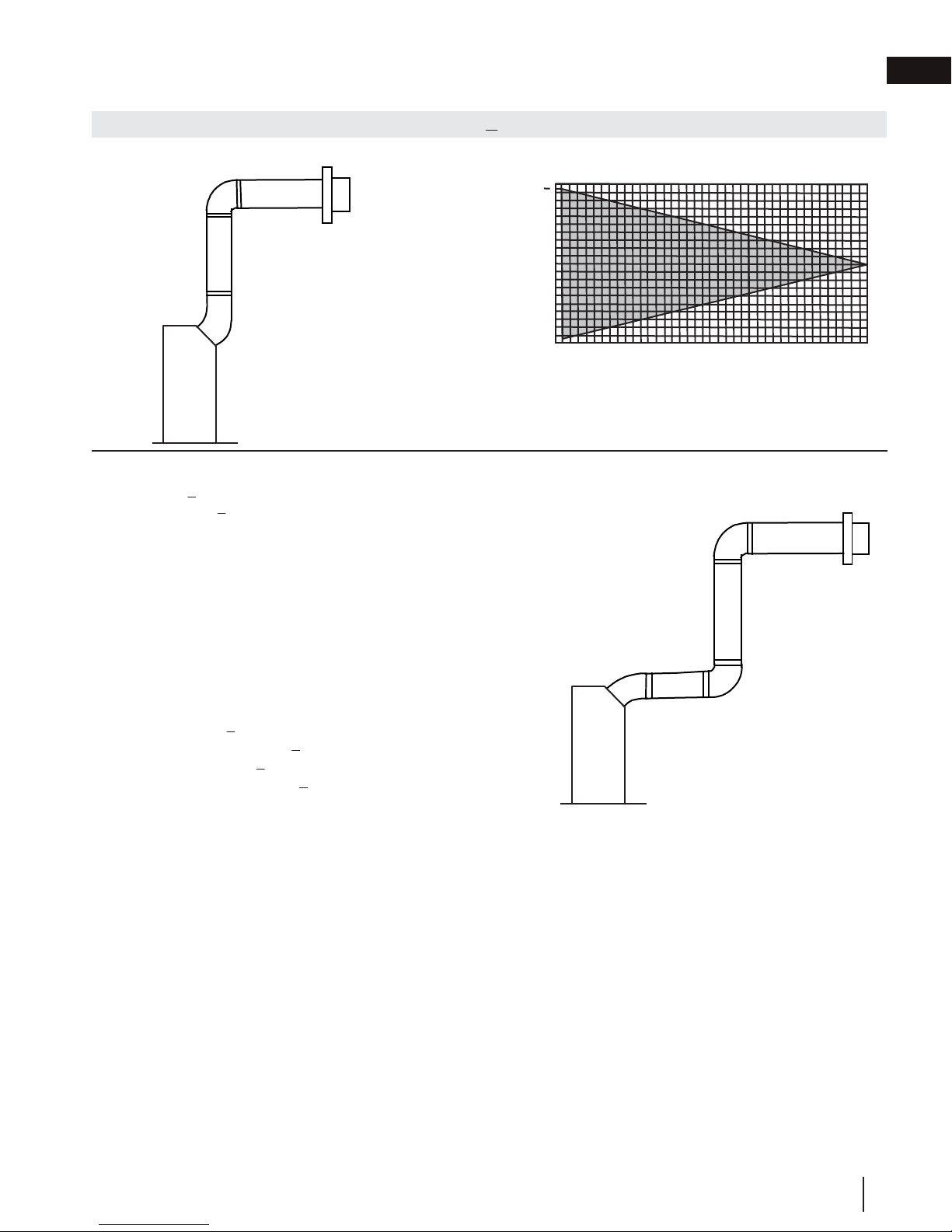
3.8 horizontal termination
90°
90°
45°
V
1
H
1
H
2
Simple venting configuration (only one 45°
and 90° elbow)
See graph to determine the required vertical rise VT for the required
horizontal run H
T
.
REQUIRED
VERTICAL RISE
IN FEET
(METERS) V
T
HORIZONTAL VENT RUN PLUS OFFSET IN FEET (METERS) H
T
The shaded area within the lines represents acceptable
values for H
T
and HT
(HT) < (VT)
For vent configurations requiring more than two 90° elbows, the following formulas apply:
Formula 1: H
T
< V
T
Formula 2: HT + V
T
< 40 feet (12.2m)
Example:
V
1
= 8 FT (2.4m)
V
T
= V
1
= 8 FT (2.4m)
H
1
= 2.5 FT (0.8m)
H
2
= 2 FT (0.6m)
H
R
= H
1
+ H
2
= 2.5FT (0.8m) + 2FT (0.6m) = 4.5FT (1.4m)
H
O
= .03 (one 45° elbows + two 90° elbows -135°) = .03 (225 - 135°) = 2.7 FT (0.8m)
H
T
= H
R
+ H
O
= 4.5FT (1.4m) + 2.7FT (0.8m) = 7.2FT (2.2m)
H
T
+ V
T
= 7.2FT (2.2m) + 8FT (2.4m) = 15.2 FT (4.6m)
Formula 1: H
T
< V
T
7.2 FT (2.2m) < 8 FT (2.4m)
Formula 2: HT + V
T
< 40 FT (12.2m)
15.2 FT (4.6m) < 40 FT (12.2m)
Since both formulas are met, this vent configuration is acceptable.
0
2.5
(0.8)5 (1.5)
7.5
(2.3)
10
(3.1)
12.5
(3.8)
15
(4.6)
10 (3.1)
20 (6.1)
30 (9.1)
17.5
(5.3)
20
(6.1)
39 (11.9)
venting requirements
EN
W415-1285 / G / 04.27.18
17
Page 18

EN
Simple venting configuration (only one
45° and 90° elbow)
See graph to determine the required vertical rise V
T
for the
required horizontal run H
T
.
REQUIRED
VERTICAL RISE IN
FEET (METERS)V
T
HORIZONTAL VENT RUN PLUS OFFSET IN FEET (METERS) H
T
The shaded area within the lines represents acceptable
values for H
T
and HT
(HT) > (VT)
For vent configurations requiring more than two 90° elbows, the following formulas apply:
Formula 1: H
T
< 4.2V
T
Formula 2: HT + V
T
< 24.75 feet (7.5m)
Example:
V
1
= 4 FT (1.2m)
V
2
= 1.5 FT (0.5m)
V
T
= V
1
+ V
2
= 4FT (1.2m) + 1.5FT (0.5m) = 5.5 FT (1.7m)
H
1
= 2 FT (0.6m)
H
2
= 1 FT (0.3m)
H
3
= 1 FT (0.3m)
H
4
= 1.5 FT (0.5m)
H
R
= H1+ H2+H3+H4= 2FT(0.6m) + 1FT(0.3m) + 1FT(0.3m) + 1.5FT(0.5m)
= 5.5 FT(1.7m)
H
O
= .03 (one 45° elbow + four 90° elbows - 135°)
= .03 (405 - 135°) = 8.1 FT (2.5m)
H
T
= H
R
+ H
O
= 5.5 FT (1.7m) + 8.1 FT (2.5m) = 13.6 FT (4.2m)
H
T
+ V
T
= 13.6 FT (4.2m) + 5.5 FT (1.7m) = 19.1 FT (5.8m)
Formula 1: H
T
< 4.2FT (1.3m) VT
4.2FT (1.3m) VT = 4.2 FT (1.3m) x 5.5 FT (1.7m)
= 23.1 FT (7m)
13.6 FT (4.2m) < 23.1 FT (7M)
Formula 2: H
T
+ V
T
< 24.75 FT (7.5m)
19.1 FT (5.8m) < 24.75 FT (7.5m)
Since both formulas are met, this vent configuration is acceptable.
0
5
(1.5)
15
(4.6)
20
(6.1)
8.3 (2.5)
4.2 (1.3)
12.5
(3.8)
4.8 (1.5)
12.3 (3.8)
10
(3.1)
90°
90°
45°
V
1
H
1
H
4
90°
90°
H
3
H
2
V
2
venting requirements
18
W415-1285 / G / 04.27.18
Page 19
3.9 vertical termination
(HT) < (VT)
Simple venting configurations.
See graph to determine the required vertical rise V
REQUIRED
VERTICAL RISE
IN FEET
(METERS) V
T
40 (12.2)
30 (9.1)
20 (6.1)
10 (3.1)
venting requirements
for the
required horizontal run H
.
T
T
EN
3 (0.9)
0
5
(1.5)
10 (3.1)
15
(4.6)
HORIZONTAL VENT RUN PLUS OFFSET IN FEET (METERS) H
The shaded area within the lines represents acceptable
values for H
and VT
T
For vent configurations requiring more than one 45° and one 90° elbow, the following formulas apply:
Formula 1: H
Formula 2: HT + V
< V
T
T
< 40 feet (12.2m)
T
Example:
= 5 FT (1.5m)
V
1
= 10 FT (3.1m)
V
2
= V
+ V
V
T
= 3 FT (0.9m)
H
1
= 2.5 FT (0.8m)
H
2
= H
H
R
= .03 (one 45° + three 90° elbows - 135°)
H
O
= .03 (45 + 270 - 135°) = 5.4 FT (1.6m)
= H
H
T
+ V
H
T
Formula 1: H
= 5 FT (1.5m) + 10 FT (3.1m) = 15 FT (4.6m)
1
2
+ H
= 3FT (0.9m) + 2.5FT (0.8m) = 5.5 FT (1.7m)
1
2
+ H
= 5.5 FT (1.7m)+ 5.4 FT (1.m) = 10.9 FT (3.3m)
R
O
= 10.9 FT (3.3m)+ 15 FT (4.6m) = 25.9 FT (7.9m)
T
< V
T
T
45°
90°
V
1
H
1
90°
10.9FT (3.3m) < 15 (4.6m)
Formula 2: HT + V
< 40 FT (12.2m)
T
25.9FT (7.9m) < 40 (12.2m)
Since both formulas are met, this vent configuration is acceptable.
20
(6.1)
T
V
2
H
2
90°
W415-1285 / G / 04.27.18
19
Page 20
EN
(HT) > (VT)
Since both formulas are met, this vent configuration is acceptable.
venting requirements
Simple venting configurations.
See graph to determine the required vertical rise V
required horizontal run H
.
T
for the
T
20 (6.1)
19 (5.8)
REQUIRED
VERTICAL RISE
IN FEET
(METERS) V
T
3 (0.9)
10 (3.1)
0
5
(1.5)
10
(3.1)
15
(4.6)
20
(6.1)
HORIZONTAL VENT RUN PLUS OFFSET IN FEET (METERS)H
The shaded area within the lines represents acceptable
values for H
and VT
T
For vent configurations requiring more than one 45° and one 90° elbow, the following formulas apply:
Formula 1: H
Formula 2: HT + V
< 3V
T
T
< 40 feet (12.2m)
T
Example:
V
= 1 FT (0.3m)
1
V
= 1.5 FT (0.5m)
2
V
= V
+ V
T
H
= 6 FT (1.8m)
1
H
= 2 FT (0.6m)
2
H
= H
R
H
= .03 (one 45° + three 90° elbows - 135°)
O
= 1 FT (0.3m)+ 1.5 FT (0.5m)= 2.5 FT (0.8m)
1
2
+ H
= 6FT (1.8m) + 2FT (0.6m) = 8 FT (2.4m)
1
2
= .03 (45 + 270 - 135°) = 5.4 FT (1.6m)
H
= H
+ H
T
H
+ V
T
Formula 1: H
3VT = 3FT (0.9m) x 2.5FT(0.8m) = 7.5FT (2.3m)
= 8FT (2.4m) + 5.4FT (1.6m) = 13.4FT (4.1m)
R
O
= 13.4FT (4.1m)+ 2.5FT (0.8m) = 15.9FT (4.8m)
T
< 3V
T
T
45°
90°
V
H
1
1
90°
13.4 FT (4.1m) > 7.5 FT (2.3m)
Since this formula is not met, this vent configuration is unacceptable.
H
25
(7.6)
2
30
(9.1)
T
V
2
90°
Formula 2: HT + V
15.9FT (4.8m) < 40FT (12.2m)
< 40 FT (12.2m)
T
Since only formula 2 is met, this vent configuration in unacceptable and a new fireplace location or vent
configuration will need to be established to satisfy both formulas.
Example:
V
= 1.5 FT (0.5m)
1
V
= 8 FT (2.4m)
2
V
= V
+ V
T
H
= 1 FT (0.3m)
1
H
= 1 FT (0.3m)
2
H
= 10.75 FT (3.3m)
3
H
= H
R
H
= .03 (three 90° elbows + two 45° elbows - 135°)
O
= 1.5 FT (0.5m) + 8 FT (2.4m) = 9.5 FT (2.9m)
1
2
+ H2 + H3 = 1FT(0.3m) + 1FT(0.3m) + 10.75FT(3.3m) = 12.75FT(3.9m)
1
= .03 (270 + 90 - 135°) = 6.75 FT (2.1m)
H
= H
+ H
T
H
+ V
T
Formula 1: H
3VT = 3 x 9.5 = 28.5 FT (8.7m)
= 12.75 FT (3.9m) + 6.75 FT (2.1m) = 19.5 FT (5.9m)
R
O
= 19.5FT (5.9m) + 9.5FT (2.9m) = 29 FT (8.8m)
T
< 3V
T
T
19.5 FT (5.9m) < 28.5 (8.7m)
Formula 2: HT + V
29 FT (8.8m) < 40 FT (12.2m)
20
W415-1285 / G / 04.27.18
< 40 FT (12.2m)
T
45°
90°
H
2
V
45°
H
1
1
H
3
V
2
90°
90°
Page 21
4.0 framing
!
WARNING
note:
When using optional fi nishing accessories, the framing dimensions and fi nishing materials may differ from
what is outlined in the section below; refer to the leafl et instructions supplied in the accessory kit for specifi c
framing and fi nishing specifi cations.
• Risk of fi re!
• In order to avoid the possibility of exposed insulation or vapour barrier coming in contact with the appliance
body, it is recommended that the walls of the appliance enclosure be “fi nished” (i.e. drywall / sheetrock),
as you would fi nish any other outside wall of a home. This will ensure that clearance to combustibles is
maintained within the cavity.
• Do not notch the framing around the appliance stand offs. Failure to maintain air space clearance may cause
over heating and fi re. Prevent contact with sagging or loose insulation or framing and other combustible
materials. Block opening into the chase to prevent entry of blown-in insulation. Make sure insulation and
other materials are secured.
• When constructing the enclosure, allow for fi nishing material thickness to maintain clearances. Framing or
fi nishing material closer than the minimums listed must be constructed entirely of non-combustible materials.
Materials consisting entirely of steel, iron, brick, tile, concrete, slate, glass or plasters, or any combination
thereof are suitable. Materials that are reported as passing ASTM E136, standard test method for behaviour
of materials in a vertical tube furnace at 1382ºF (750ºC) and UL763 shall be considered non-combustible
materials.
• Minimum clearance to combusibles must be maintained or a serious fi re hazard could result.
• The appliance requires a minimum enclosure height. Measure from the appliance base.
• If steel stud framing kits with cement board are provided, or specifi ed in the installation instructions, they
must be installed.
• If specifi ed in the installation instruction, fi nishing must be done using a non-combustible board, ceramic tile,
marble, etc. Do NOT use wood or drywall. Any fi re rated drywall is not acceptable.
framing
EN
It is best to frame your appliance after it is positioned and the vent system is installed.
When roughing in the appliance, raise the appliance to accommodate for the thickness of the finished floor materi-
als, i.e. tile, carpeting and hard wood.
Maintain these minimum clearances to combustibles from appliance and vent surfaces:
Combustible Appliance framing:
- 1/4" (6.4mm) to the sides of appliance
- 8 1/4" (210mm) to the top of appliance
Combustible Appliance finishing:
- 0" (0mm) above the appliance opening
- 50" (127cm) from bottom of appliance to enclosure top
- 62 1/4" (158.2cm) from bottom of appliance to ceiling
- 3" (76mm) to top of vent pipe*
- 2" (51mm) to sides and bottom of vent pipe*
- 0" (0mm) to the sides and top of appliance
*HORIZONTAL VENT SECTIONS: A minimum clearance of 3" (76mm) to the top and 2" (51mm) to the sides and
bottom of the vent pipe on all horizontal runs to combustibles is required, see "minimum clearance to combustible
enclosures" section. Use firestop assembly W010-3210. If reduced to 4/7", use W010-3440 firestop.
note:
The minimum clearances around the horizontal vent pipe to combustible materials may be reduced from 3"
(76.2mm) / 2" (50.8mm) to 1" (25mm) in those installations with a minimum 52" (132cm) vertical vent rise made
immediately off the appliance collar and where the vent has been reduced to 4/7" from 5/8" at the appliance
collars.
*VERTICAL VENT SECTIONS: A minimum of 2" (51mm) all around the vent pipe on all vertical runs to
combustibles is required. Use firestop spacer W010-3210.
W415-1285 / G / 04.27.18
21
Page 22
EN
A
B
46 1/2"
[118cm]
framing
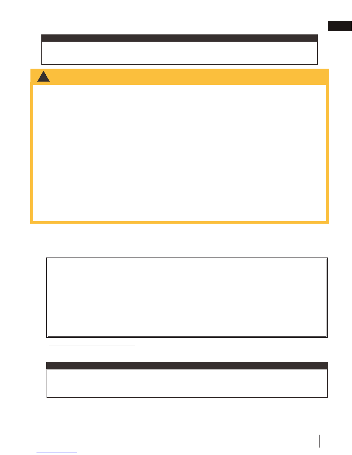
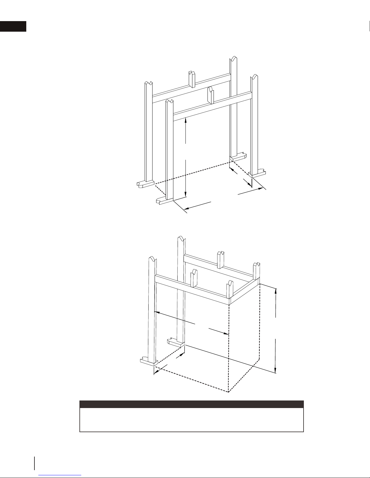
4.1 framing
4.1.1 see-thru framing (BHD4ST)
4.1.2 peninsula framing (BHD4P)
A: MIN 22 1/8" (56.2cm)
MAX 24 1/8" (61.3cm)
46 1/2"
[118cm]
A: MIN 22 1/8" (56.2cm)
MAX 24 1/8" (61.3cm)
A
45 1/2"
[115.6cm]
B: MIN 42 1/2" (108cm)
MAX 43 1/2" (110.5cm)
22
W415-1285 / G / 04.27.18
note:
All framing dimensions are based on the finishing material supports position.
Framing may change depending on the finishing material thickness (see
"finishing support adjustment" section).
Page 23
Combustible
Non-combustible
Brick
3" [76mm]
2"
[51mm]
Firestop
43"
[109.2cm]
minimum
rise**
45" [114.3cm]
6" [152mm]
minimum wall
38 1/4"
[97.2cm]
SAFETY BARRIER
3" [76mm] *
62 1/4"
[158cm]
11 3/4"
[298mm]
50"
[127cm]
minimum
enclosure
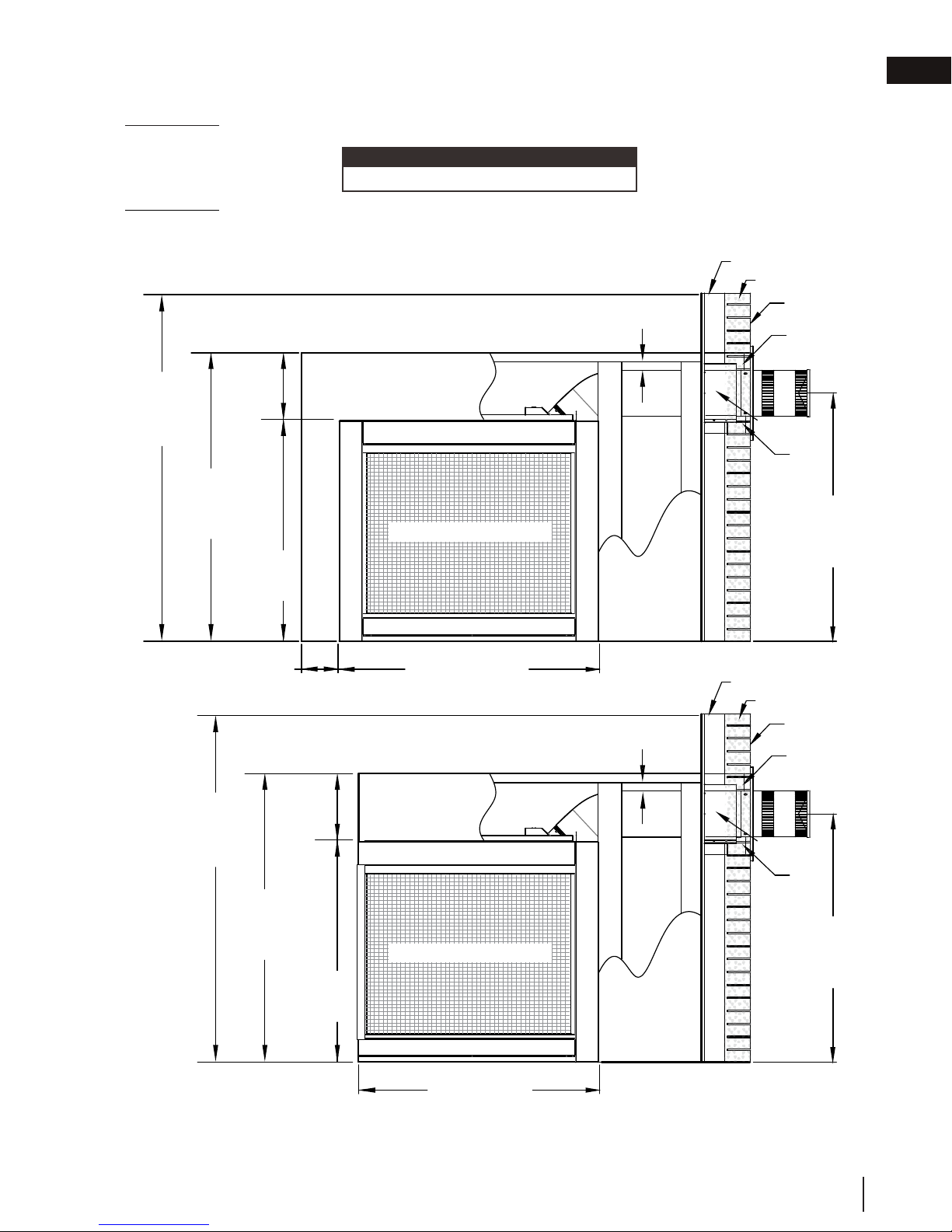
4.2 minimum clearance to combustible enclosures
IMPORTANT: This appliance requires a minimum inside enclosure height of 50" (127cm), measured from the bot-
tom of the appliance. For temperature requirements, this area must be left unobstructed.
note:
This appliance is not load bearing.
IMPORTANT: The firestop assembly provided must be used when the vent pipes pass through any
walls or are terminated horizontally.
If reduced to 4/7" venting, a new firestop is required (W010-3440).
4.2.1 see-thru (BHD4ST)
62 1/4"
[158cm]
minimum
to ceiling
[298mm]
50"
[127cm]
minimum
enclosure
6" [152mm]
minimum wall
11 3/4"
SAFETY BARRIER
38 1/4"
[97.2cm]
45" [114.3cm]
4.2.2 peninsula (BHD4P)
3" [76mm] *
3" [76mm] *
framing
Combustible
Non-combustible
Brick
3" [76mm]
Firestop
[51mm]
Combustible
Non-combustible
Brick
3" [76mm]
EN
2"
43"
[109.2cm]
minimum
rise**
62 1/4"
[158cm]
minimum
to ceiling
minimum
enclosure
11 3/4"
[298mm]
50"
[127cm]
38 1/4"
[97.2cm]
* Within the appliance enclosure a minimum 3” (76mm) clearance between the top of the vent pipe and combustible
materials is required. All other clearances within the enclosure, including where the vent pipe exits the enclosure are
subject to 2” (51mm) to the sides and bottom and 3” (76mm) to the top for horizontal and 2” (51mm) for vertical.
** See "venting" section.
SAFETY BARRIER
43 1/4" [110cm]
Firestop
2"
[51mm]
43"
[109.2cm]
minimum
rise **
W415-1285 / G / 04.27.18
23
Page 24

EN
!
WARNING
5.0 venting installation
venting installation
• Ensure to unpack all loose materials from inside the fi rebox prior to connecting the gas and electrical supply
• If your appliance is supplied with a remote, ensure the remote receiver is in the “OFF” position prior
to connecting the gas and electrical supply to the appliance.
• For safe and proper operation of the appliance, follow the venting instructions exactly.
• The appliance exhaust fl ue collar must be sealed using Mill Pac. All exhaust and intake vent pipe joints
must be sealed using red RTV high temp silicone sealant (W573-0002) (not supplied) or black high temp Mill
Pac (W573-0007) (not supplied).
• If using pipe clamps to connect rigid vent components, a minimum of 3 screws must also be used to ensure
the connection cannot slip off.
• Do not clamp the fl exible vent pipe.
• Risk of fi re, explosion, or asphyxiation. Improper support of the entire venting system may allow vent to sag
and separate. Use vent run supports and connect vent sections per installation instructions.
• Risk of fi re, do not allow loose materials or insulation to touch the vent pipe. Remove insulation to allow for the
installation of the attic shield and to maintain clearances to combustibles.
• Do not fi ll the space between the vent pipe and enclosure with any type of material. Do not pack insulation
or combustibles between ceiling fi restops. Always maintain specifi ed clearances around venting and fi restop
systems. Install wall shields and fi restops as specifi ed. Failure to keep insulation or other materials away from
vent pipe may cause fi re.
For optimum performance it is recommended that all horizontal runs have a minimum of 1/4” (6mm) rise per foot/
meter using flexible venting. For safe and proper operation of the appliance, follow the venting instructions exactly.
For clearance to combustible materials from the vent pipe, see "minimum clearance to combustibles" section.
note:
The firestop / vent shield supplied with this appliance must be used when
passing through a combustible wall or floor.
24
W415-1285 / G / 04.27.18
Page 25
venting installation
between the pipe and the fi restop.
Determine
the
correct
height
Firestop
spacer
Vent
shield
Finishing
material
Caulking
WARNING
This application occurs when venting through a roof. Installation kits for
insulation, from fi lling up the 1" (25mm) air space around the pipe.
5.1 horizontal installation
!
• The fi restop assembly must be installed with the vent shield to the top.
• Terminals must not be recessed into a wall or siding more than the depth of the return fl ange of the mounting
plate.
14”
This application occurs when venting through an exterior
wall. Having determined the correct height for the air
terminal location, cut and frame a hole in the exterior wall,
as illustrated, to accommodate the fi restop assembly. Dry
CAULKING
VENT
SHIELD
fi t the fi restop assembly before proceeding to ensure the
brackets on the rear surface fi t to the inside surface of the
horizontal framing.
FIRESTOP
SPACER
The vent shield must be installed to the full depth of the
combustible wall. The length of the vent shield may cut
shorter for combustible walls that less than 6” (152mm)
thick.
CAULKING
note:
Bend the tabs for reduced side clearances or move
the shield for reduced top clearances. Do not fi ll
the air space between the fi restop spacer and the
exterior wall with any type of insulating material (i.e.
spray foam).
A. Apply a bead of caulking (not supplied) around the
corner edge of the inside surface of the fi restop
assembly, fi t the fi restop assembly to the hole and
note:
The above is for illustration purposes only. Vents do
not always pass through center of frame.
secure using 4 screws.
B. Once the vent pipe is installed in its fi nal position, apply red RTV silicone (W573-0002) (not supplied)
ADD
(35.6CM)
HEIGHT
height
FINISHING
MATERIAL
(35,6CM)
DETERMINE
THE
CORRECT
HEIGHT
ADD
14”
WIDTH
width
EN
5.2 vertical installation
various roof pitches are available from your authorized dealer / distributor.
See the “accessories” section to order specifi c kits required.
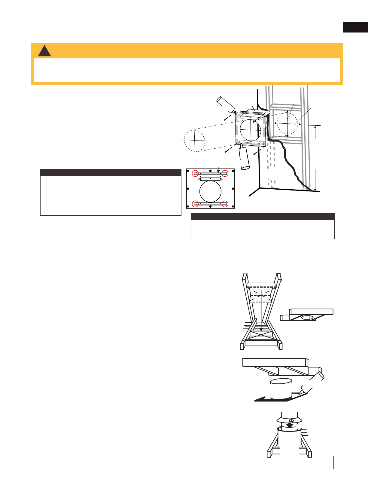
A. Determine the air terminal location, cut and frame a square opening,
as illustrated, in the ceiling and the roof to provide the minimum 1"
(25mm) clearance between the vent pipe and any combustible material.
Try to center the vent pipe location midway between two joists to
prevent having to cut them. Use a plumb bob to line up the center of
the openings. A vent pipe shield will prevent any materials such as
insulation, from fi lling up the 1" (25mm) air space around the pipe. Nail
headers between the joist for extra support.
B. Apply a bead of caulking (not supplied) to the framework or to the
Wolf Steel vent pipe shield plate or equivalent (in the case of a fi nished
ceiling), and secure over the opening in the ceiling. A fi restop must be
placed on the bottom of each framed opening in a roof or ceiling that
the venting system passes through. Apply a bead of caulking all around
and place a fi restop spacer over the vent shield to restrict cold air from
being drawn into the room or around the fi replace. Ensure that both
spacer and shield maintain the required clearance to combustibles.
Once the vent pipe is installed in its fi nal position, apply red RTV
silicone (W573-0002) (not supplied) between the pipe and the fi restop
assembly.
C. In the attic, slide the vent pipe collar down to cover up the open end
of the shield and tighten. This will prevent any materials, such as
Vent Pipe
Shield
Vent
Pipe
Shield
Firestop
underside
of joist
Caulking
Vent
Pipe
Collar
W415-1285 / G / 04.27.18
25
Page 26
EN
!
WARNING
venting installation
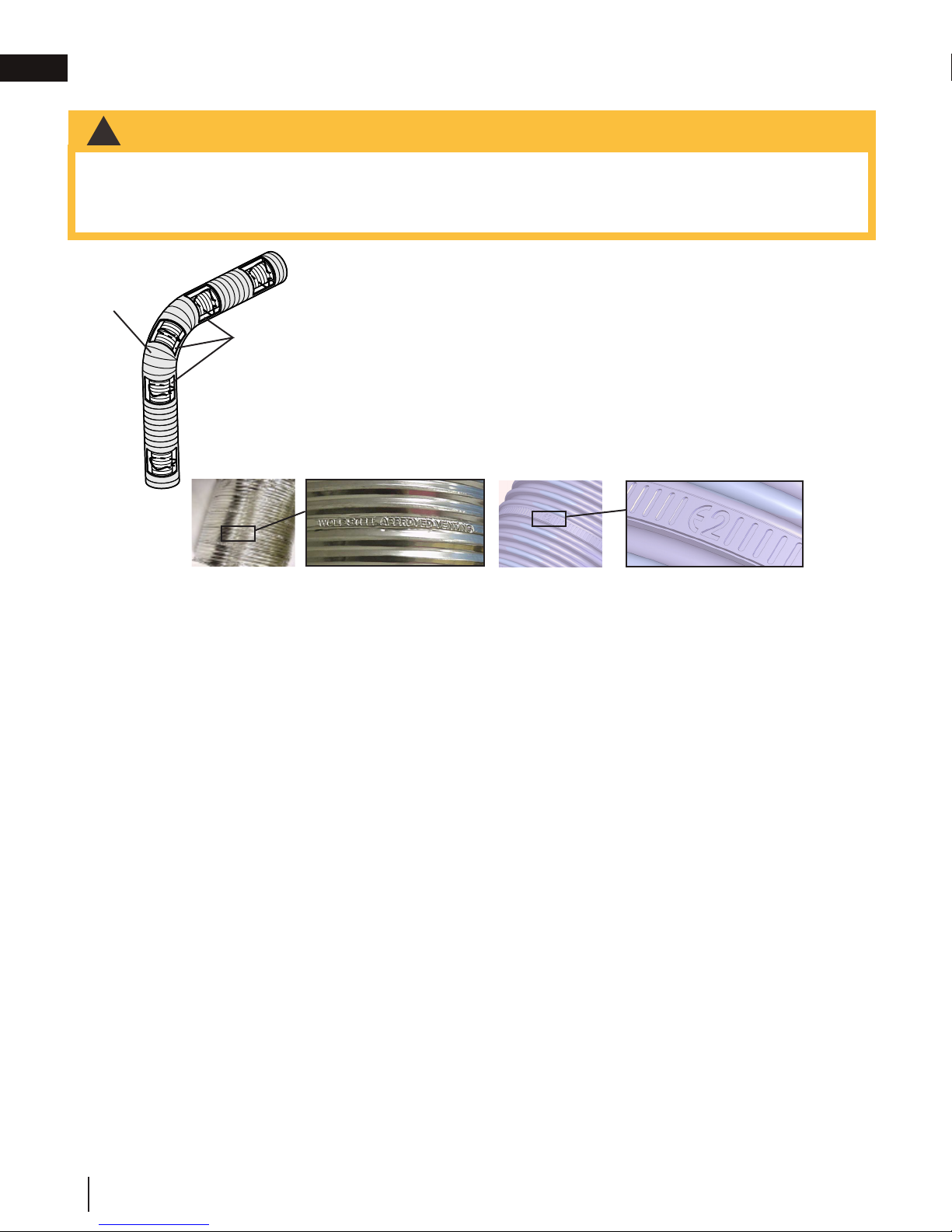
5.3 using flexible vent components
• Do not allow the inner fl ex pipe to bunch up on horizontal or vertical runs and elbows. Keep it pulled tight.
• Spacers are attached to the inner fl ex pipe at predetermined intervals to maintain an even air gap to the outer
fl ex pipe. This gap is required for safe operation. A spacer is required at the start, middle, and end of each
elbow to ensure this gap is maintained. These spacers must not be removed.
For safe and proper operation of the appliance, follow the venting instructions
exactly.
Elbow
Spacers
The vent system must be supported approximately every 3 feet (0.9m) for
both vertical and horizontal runs. Use Wolf Steel Ltd. support ring assembly
or equivalent noncombustible strapping to maintain the minimum clearance to
combustibles for both vertical and horizontal runs.
All inner fl ex pipe and outer fl ex pipe joints may be sealed using high temperature
red RTV silicone W573-0002 (not supplied) or the high temperature sealant W5730007 Mill Pac (not supplied). However, the high temperature sealant W573-0007
Mill Pac (not supplied) must be used on the joint connecting the inner fl ex pipe and
the exhaust fl ue collar.
Use only approved fl exible vent pipe kits marked:
“Wolf Steel Approved Venting” or “E2” as identifi ed by the stamp only on the fl ex pipes.
When installing using rigid vent components, follow the manufacturer’s installation and vent sealing requirements.
26
W415-1285 / G / 04.27.18
Page 27
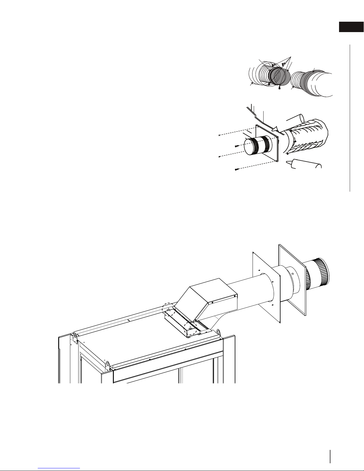
5.3.1 horizontal air terminal installation
A. Stretch the inner fl ex pipe to the required length taking
depth of its return fl ange.
ADD FASTENER TYPE
Screws
(Supplied)
2" (50.8mm) Overlap
Outer Flex Pipe
Inner Flex
Pipe
Red RTV Silicone
Caulking
Outer Flex Pipe
Outer Flex
venting installation
EN
into account the additional length needed for the fi nished
wall surface. Apply a heavy bead of the red RTV silicone
(W573-0002) (not supplied) to the inner sleeve of the air
Red RTV Silicone
Screws
Inner Coupler
Outer Coupler
terminal. Slip the vent pipe a minimum of 2” (50.8mm)
over the inner sleeve of the air terminal and secure with a
minimum of 3 screws.
B. Using the outer fl ex pipe, slide over the outer combustion
air sleeve of the air terminal and secure with a minimum
Outer Flex
Pipe
Inner Flex
Pipe
Pipe
of 3 screws. Seal using red RTV silicone (W573-0002)
(not supplied).
C. Insert the vent pipes through the fi restop maintaining
Caulking
the required clearance to combustibles. Holding the air
terminal (lettering in an upright, readable position), secure
to the exterior wall and make weather tight by sealing
ADD GRAPHIC
Inner Flex
Pipe
with caulking (not supplied).
D. If more vent pipe needs to be used to reach the fi replace,
2" (50.8mm) Overlap
couple them together, as illustrated. The vent system
must be supported approximately every 3 feet (0.9m) for
both vertical and horizontal runs. Use non-combustible
strapping to maintain the minimum clearance to
Screws
(Supplied)
Red RTV Silicone
combustibles.
E. The vent shield must be installed only when terminating horizontally. Remove the two screws nearest
E. Stove Appliances Only: From inside the house, using
the vent collars on the top of the appliance. Align the vent heat shield (supplied) and secure. Adjust
the vent heat shield to touch the firestop spacer, as shown below.
Red RTV Silicone (W573-0002) (not supplied), seal
between the vent pipe and the fi restop. Then slide the black trim collar over the vent pipe up to the
fi restop.
The air terminal mounting plate may be recessed into the exterior wall or siding no greater than the
W415-1285 / G / 04.27.18
27
Page 28

EN
air terminal installation” section.
!
WARNING
A. Install the inner fl ex pipe to the appliance. Secure with a minimum of
INSERT
ADD FASTENER TYPE
45 VENT - FLEX 45 VENT - RIGID/FLEX
#8 X 1/2”
Self Drilling
Screws
Mill Pac
Sealant
2” (50.8mm)
Overlap
venting installation
5.3.2 vertical air terminal installation
• Maintain a minimum 2” (51mm) space between the air inlet base and the storm collar.
note:
Fastening hardware provided with appropriate roof terminal and liner kits.
A. Fasten the roof support to the roof using 6 screws. The roof support is
optional. In this case, the venting is to be adequately supported using
either an alternate method suitable to the authority having jurisdiction or
the optional roof support.
B. Stretch the inner fl ex pipe to the required length. Slip the inner fl ex
pipe a minimum of 2” (51mm) over the inner pipe of the air terminal
connector and secure with a minimum of three screws, when 4/7, 5/8
and 3/5 venting is used and a minimum of six screws when using 8/10
or 8/11 venting. Seal using a heavy bead of red RTV silicone sealant
(W573-0002) (not supplied).
C. Repeat using the outer fl ex pipe, using a heavy bead of red RTV
silicone sealant (W573-0002) (not supplied) and a minimum of three
screws, when 4/7, 5/8 and 3/5 venting is used and a minimum of six
screws when using 8/10 or 8/11 venting.
D. Thread the air terminal connector / vent pipe assembly down through
the roof. The air terminal must be positioned vertically and plumb.
Attach the air terminal connector to the roof support, ensuring that the
top of the air terminal is 16” (40.6cm) above the highest point that it
penetrates the roof.
E. Remove nails from the shingles, above and to the sides of the air
terminal connector. Place the fl ashing over the air terminal connector
leaving a min. 3/4” (19mm) of the air terminal connector showing above
the top of the fl ashing. Slide the fl ashing underneath the sides and
upper edge of the shingles. Ensure that the air terminal connector is
properly centered within the fl ashing, giving a 3/4” (19mm) margin all
around. Fasten to the roof. Do not nail through the lower portion of the
fl ashing. Make weather-tight by sealing with caulking. Where possible,
cover the sides and top edges of the fl ashing with roofi ng material.
F. Aligning the seams of the terminal and air terminal connector, place the
terminal over the air terminal connector making sure the vent pipe goes
into the hole in the terminal. Secure with a minimum of three screws,
when 4/7, 5/8 and 3/5 venting is used and a minimum of six screws
when using 8/10 or 8/11 venting.
G. Apply a heavy bead of weatherproof caulking 2” (51mm) above the
fl ashing. Install the storm collar around the air terminal and slide down
to the caulking. Tighten to ensure that a weather-tight seal between the
air terminal and the collar is achieved.
H. If more vent pipe needs to be used to reach the appliance, see “horizontal
Connector
2” (51mm)
Roof Support
Inner Pipe
Air
Terminal
Red RTV
Silicone
(W572-0002)
Inner Flex Pipe
Outer Flex Pipe
Air Inlet
Base
Caulking
Sto r m Collar
Weather
Sealant
Flashing
5.3.3 appliance vent connection
28
W415-1285 / G / 04.27.18
three screws when installing 3”/5”, 4”/7” or 5”/8” venting, or six screws
when installing 8”/10” or 8”/11” venting. Seal the joint and screw holes
using Mill Pac sealant (W573-0007) (not supplied).
B. Install the outer fl ex pipe to the appliance. Secure with a minimum of
three screws when installing 3”/5”, 4”/7” or 5”/”8 venting, or six screws
when installing 8”/10” or 8”/11” venting. Seal the joints using high
temperature red RTV silicone (W573-0002) (not supplied).
#8 X 1/2”
Self Drilling
Screws
IMAGE HERE
2” (50.8mm)
Overlap
Mill Pac
Sealant
Page 29
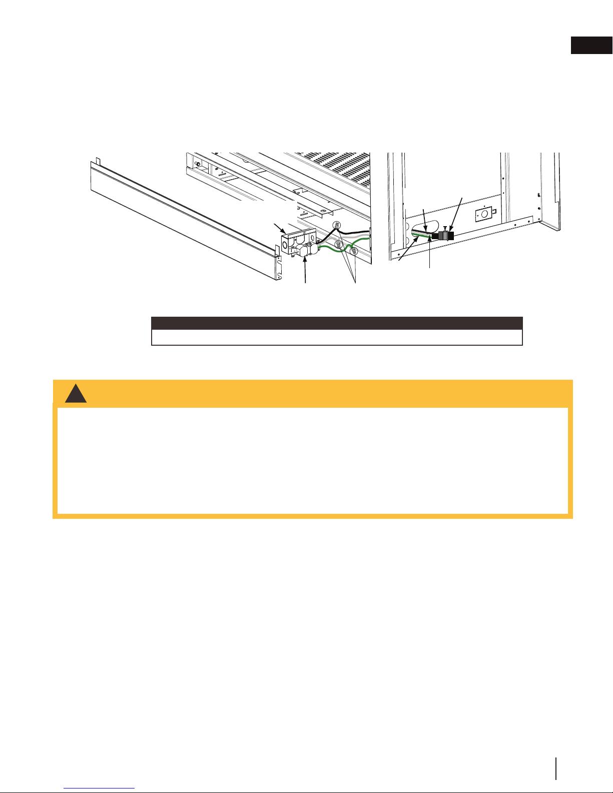
6.0 electrical information
ELECTRICAL
COVER
CABLE
CONNECTOR
L1
(BLACK)
L2
(WHITE)
GROUND
(GREEN)
CONTROL BOX
WIRE
NUTS
GROUND
(GREEN)
3 PRONGE
RECEPTACLE
ELECTRICAL BOX
(BLACK)
(WHITE)
!
WARNING
electrical information
6.1 hard wiring connection
It is necessary to hard wire this appliance.
Permanently framing the appliance with an enclosure, requires the appliance junction box to be hard wired.
This appliance must be electrically connected and grounded in accordance with local codes. In the absence of
local codes, use the current CSA C22.1 Canadian electrical code in Canada or the ANSI/NFPA national electrical
code in the United States.
6.2 receptacle wiring diagram
EN
6.3 electronic wiring diagram
CABLE
CONNECTOR
ELECTRICAL
BOX
RECEPTACLE
3 PRONG
WIRE
NUTS
(BLACK)
GROUND
(GREEN)
L1
L2
(WHITE)
note:
Ensure that the transformer is plugged into the receptacle.
• Do not use this appliance if any part has been under water. Call a qualifi ed service technician immediately to
have the appliance inspected for damage to the electrical circuit.
• Risk of electrical shock or explosion. Do not wire 110V to the valve or to the appliance wall switch. Incorrect
wiring will damage controls.
• All wiring should be done by a qualifi ed electrician and shall be in compliance with local codes. In the
absence of local codes, use the current CSA22.1 Canadian Electric Code in Canada or the current National
Electric Code ANSI/NFPA NO. 70 in the United States.
• Always light the pilot whether for the fi rst time or if the gas supply has run out, with the glass door opened or
removed.
W415-1285 / G / 04.27.18
29
Page 30
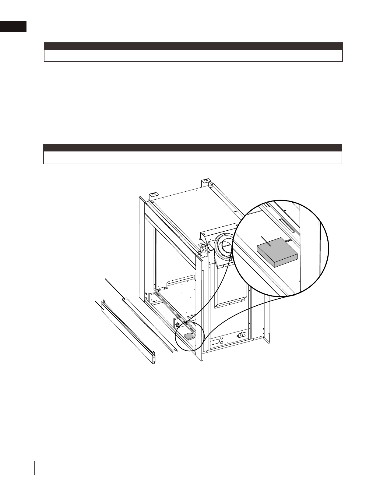
EN
electrical information
6.4 battery back-up installation
note:
In the event of a power failure, your appliance can be operated using the supplied battery back-up.
A. Remove the safety screen and door, refer to the "main safety barrier removal / installation" and "main door
removal / installation" sections for detailed removal instructions.
B. Remove the panel cover using the two finger holes, then remove the control panel cover by lifting it up
and off of the four shoulder screws. This will allow you to easily access the battery housing.
C. Remove your battery housing to install the batteries, this will be located in the control compartment,
as shown below.
D. Install the four “AA” batteries, ensure the positive and negative ends correspond with those identified on the
battery housing.
E. Place the battery housing back into position or let it rest on the hearth, for the duration of the power failure.
note:
Once the power has been restored, remove the batteries from the holder.
PANEL COVER
CONTROL
PANEL COVER
BATTERY
HOUSING
30
W415-1285 / G / 04.27.18
Page 31

6.5 wiring diagram
WARNING
note:
!
• Do not wire 110 volts to the valve or wall switch.
ACS/IPI
SWITCH
(OPTIONAL)
electrical information
EN
BATTERY
HOUSING
OFF ON
TRANSFORMER
DISCONNECT THESE
CONNECTIONS TO THE
ON/OFF SWITCH. CONNECT
AN OPTIONAL THERMOSTAT
OR REMOTE CONTROL AND
(IF ALLOWED WITH THIS
APPLIANCE) A “B” VENT
DC SUPPLY
ON / OFF
ADAPTOR.
ON / OFF
SWITCH
IPI / CPI
GROUND
GROUND
EYELET
VALVE
ORANGE
GREEN
ELECTRONIC
VALVE
IPI BOARD
DFC
WHERE APPLICABLE, APPLIANCES WITH “B” VENT ADAPTORS MUST HAVE THE SPILL SWITCH WIRED IN
SERIES WITH EITHER THE EXISTING SWITCH OR OPTIONAL WALL SWITCH, THERMOSTAT OR REMOTE.
This appliance comes equipped with a battery back-up. If this backup is used, install 4 ‘AA’ batteries (not supplied) into the holder and connect to the wire harness. Connect the battery holder to the wire harness before
using the appliance. Place near the IPI board. If the backup is used, it must be connect to this 6 volt battery
pack (supplied).
DFC
DC
IPI
CPI
ACS
Legend
Digital Fireplace Control
Direct Current
Intermittent Pilot Ignition
Continuous Pilot Ignition
Anti-Condensation Switch
W415-1285 / G / 04.27.18
-
31
Page 32

EN
!
WARNING
• Check for gas leaks by brushing on a soap and water solution. Do not use open fl ame.
7.0 gas installation
gas installation
• Risk of fi re, explosion, or asphyxiation. Ensure there are no ignition sources such as sparks or open fl ames.
• Support gas control when attaching gas supply pipe to prevent damaging gas line.
• Always light the pilot whether for the fi rst time or if the gas supply has run out with the glass door opened
or removed. Purging of the gas supply line should be performed by a qualifi ed service technician. Ensure
that a continuous gas fl ow is at the burner before closing the door. Ensure adequate ventilation. For gas and
electrical locations, see “dimensions” section.
• All gas connections must be contained within the appliance when complete (gas fi replaces only).
• High pressure will damage valve. Disconnect gas supply piping before testing gas line at test pressures above
1/2 PSIG.
• Valve settings have been factory set, do not change.
Installation and servicing to be done by a qualifi ed installer.
• Move the appliance into position and secure.
• If equipped with a fl ex connector, the appliance is designed to accept a 1/2” (13mm) gas supply. Without the
connector, it is designed to accept a 3/8” (9.5mm) gas supply. The appliance is equipped with a manual shut
off valve to turn off the gas supply to the appliance.
• Connect the gas supply in accordance to local codes. In the absence of local codes, install to the current
CAN/CSA-B149.1 Installation Code in Canada or to the current National Fuel Gas Code, ANSI Z223.1 / NFPA
54 in the United States.
• When fl exing any gas line, support the gas valve so that the lines are not bent or kinked.
• The gas line fl ex-connector should be installed to provide suffi cient movement for shifting the burner assembly
on its side to aid with servicing components.
After installing the electrical wiring and gas lines, ensure to test the appliance before finishing the framing and
finishing the appliance.
7.1 access panel for gas line connection
A. Remove the screen and door from the appliance, see "main screen removal / door removal" section.
B. Remove media and media tray from the appliance, see "cradle burner removal" section.
C. Unscrew the 2 screws that hold the access panel to the firebox.
D. Remove the gasket (careful not to tear).
Access
Panel
Gasket
32
W415-1285 / G / 04.27.18
Page 33

8.0 nailing tab installation
A. Nailing tabs are provided as part of the frames, as shown. To
* Additional fasteners may be installed.
1/2” FINISHING
MATERIAL
3/4” FINISHING
MATERIAL
nailing tab installation
EN
determine the final location and where to bend the nailing tabs you
must first determine the thickness of your finishing material (i.e.
drywall). This will determine the dimension from the front edge of the
corner post to the nailing tab. Once the nailing tab is in the desired
location and secure using an appropriate fastener*.
ADD
NAILING
TABS
IMAGE
HERE
W415-1285 / G / 04.27.18
33
Page 34

EN
9.0 operating instructions
nailing tab installation
When lit for the first time, the appliance will emit a slight odour for a few hours. This is a normal temporary
condition caused by the “burn-in” of internal paints and lubricants used in the manufacturing process and will not
occur again. Simply open a window to sufficiently ventilate the room. After extended periods of non-operation
such as following a vacation or a warm weather season, the appliance may emit a slight odour for a few hours.
This is caused by dust particles in the heat exchanger burning off. Open a window to sufficiently ventilate the
room.
9.1 operating instructions - for your safety read before operating
FOR YOUR SAFETY READ BEFORE OPERATING / POUR VOTRE SÉCURITÉ LIRE AVANT DE FAIRE FONCTIONNER
WARNING: DO NOT TURN ON IF CHILDREN OR OTHER AT RISK
INDIVIDUALS ARE NEAR THE APPLIANCE. IF YOU DO NOT FOLLOW THESE
INSTRUCTIONS EXACTLY, A FIRE OR EXPLOSION MAY RESULT CAUSING
PROPERTY DAMAGE, PERSONAL INJURY OR LOSS OF LIFE.
INITIAL LIGHTING OF THE PILOT AND MAIN BURNERS MUST BE DONE
WITH THE GLASS DOOR OFF.
DO NOT CONNECT VALVE OR WALL SWITCH TO ELECTRICITY. SEE
INSTALLATION INSTRUCTIONS.
A. THIS APPLIANCE IS EQUIPPED WITH AN IGNITION DEVICE WHICH AUTOMATICALLY
LIGHTS THE PILOT. DO NOT TRY TO LIGHT BY HAND.
B. BEFORE OPERATING, SMELL ALL AROUND THE APPLIANCE AREA FOR GAS AND NEXT TO
THE FLOOR BECAUSE SOME GAS IS HEAVIER THAN AIR AND WILL SETTLE ON THE
FLOOR.
WHAT TO DO IF YOU SMELL GAS:
• TURN OFF ALL GAS TO THE APPLIANCE.
• OPEN WINDOWS.
• DO NOT TRY TO LIGHT ANY APPLIANCE.
• DO NOT TOUCH ANY ELECTRICAL SWITCH; DO NOT USE ANY PHONE IN YOUR
BUILDING.
• IMMEDIATELY CALL YOUR GAS SUPPLIER FROM A NEIGHBOUR’S PHONE. FOLLOW THE
GAS SUPPLIER’S INSTRUCTIONS.
• IF YOU CANNOT REACH YOUR GAS SUPPLIER, CALL THE FIRE DEPARTMENT.
C. DO NOT TRY TO REPAIR ANY PART OF THIS ASSEMBLY. CALL A QUALIFIED SERVICE
TECHNICIAN. FORCE OR ATTEMPTED REPAIR MAY RESULT IN A FIRE OR EXPLOSION.
D. DO NOT USE THIS APPLIANCE IF ANY PART HAS BEEN UNDER WATER. IMMEDIATELY
CALL A QUALIFIED SERVICE TECHNICIAN TO INSPECT THE APPLIANCE AND REPLACE
ANY PART OF THE CONTROL SYSTEM AND ANY GAS CONTROL WHICH HAS BEEN UNDER
WATER.
9.2 lighting instructions
OPERATING INSTRUCTIONS / INSTRUCTIONS D’OPÉRATION
ATTENTION: NE PAS ALLUMER SI DES ENFANTS OU D’AUTRES
INDIVIDUS À RISQUE SONT À PROXIMITÉ DU FOYER. QUICONQUE NE
RESPECTE PAS À LA LETTRE LES INSTRUCTIONS DANS LA PRÉSENTE
NOTICE, RISQUE DE DÉCLENCHER UN INCENDIE OU UN EXPLOSION
ENTRAÎNANT DES DOMMAGES, DES BLESSURES OU LA MORT.
L’ALLUMAGE INITIAL DE LA VEILLEUSE ET DU BRÛLEUR PRINCIPAL
DOIT SE FAIRE AVEC LA PORTE VITRÉE ENLEVÉE.
NE RACCORDEZ PAS LA SOUPAPE OU L’INTERRUPTEUR MURAL À
L’ÉLECTRICITÉ. CONSULTEZ LES INSTRUCTIONS D’INSTALLATION.
A. CET APPAREIL EST MUNI D’UN DISPOSITIF D’ALLUMAGE QUI ALLUME
AUTOMATIQUEMENT LA VEILLEUSE. NE TENTEZ PAS D’ALLUMER LA VEILLEUSE
MANUELLEMENT.
B. AVANT DE FAIRE FONCTIONNER, RENIFLEZ TOUT AUTOUR DE L’APPAREIL POUR
DÉCELER UN ODEUR DE GAZ. RENIFLEZ PRÈS DU PLANCHER, CAR CERTAINS GAZ
SONT PLUS LOURDS QUE L’AIR ET PEUVENT S’ACCUMULER AU NIVEAU DU SOL.
QUE FAIRE SI VOUS DÉTECTEZ UNE ODEUR DE GAZ:
• COUPEZ L’ALIMENTATION DE GAZ PRINCIPALE.
• OUVREZ LES FENÊTRES.
• NE PAS TENTER D’ALLUMER D’APPAREIL.
• NE TOUCHEZ À AUCUN INTERRUPTEUR; NE PAS VOUS SERVIR DES TÉLÉPHONES SE
TROUVANT DANS LE BÂTIMENT.
• APPELEZ IMMÉDIATEMENT VOTRE FOURNISSEUR DE GAZ DEPUIS UN VOISIN.
SUIVEZ LES INSTRUCTIONS DU FOURNISSEUR.
• SI VOUS NE POUVEZ REJOINDRE LE FOURNISSEUR APPELEZ LE SERVICE DES
INCENDIES.
C. N’ESSAYEZ PAS DE RÉPARER AUCUNE PIÈCE DE CET ASSEMBLAGE. APPELEZ UN
TECHNICIEN QUALIFIÉ. FORCER OU TENTER DE RÉPARER L’ASSEMBLAGE POURRAIT
CAUSER UN FEU OU UNE EXPLOSION.
D. N’UTILISEZ PAS CET APPAREIL S’IL A ÉTÉ PLONGÉ DANS L’EAU, MÊME
PARTIELLEMENT. FAITES INSPECTER L’APPAREIL PAR UN TECHNICIEN QUALIFIÉ ET
REMPLACEZ TOUTE PARTIE DU SYSTÈME DE CONTRÔLE ET TOUTE COMMANDE QUI
ONT ÉTÉ PLONGÉS DANS L’EAU.
W385-0460 / E
LIGHTING INSTRUCTIONS / INSTRUCTIONS D’ALLUMAGE
1. STOP! READ ALL INFORMATION OF OPERATING AND LIGHTING
INSTRUCTIONS BEFORE PROCEEDING.
2. TURN OFF ELECTRICAL POWER TO THE APPLIANCE.
3. THIS APPLIANCE IS EQUIPPED WITH AN IGNITION DEVICE WHICH
AUTOMATICALLY LIGHTS THE PILOT. DO NOT TRY TO LIGHT THE PILOT
BY HAND.
4. OPEN THE GLASS DOOR.
5. TURN MANUAL SHUTOFF VALVE CLOCKWISE TO OFF.
6. WAIT FIVE (5) MINUTES TO CLEAR OUT ANY GAS. IF YOU SMELL GAS,
INCLUDING NEAR THE FLOOR, STOP! FOLLOW “B” OF THE OPERATING
INSTRUCTIONS. IF YOU DON’T SMELL GAS, GO TO THE NEXT STEP.
7. TURN MANUAL SHUTOFF VALVE COUNTER-CLOCKWISE TO ON.
8. CLOSE THE GLASS DOOR.
9. TURN ON ALL ELECTRICAL POWER TO THE APPLIANCE.
10. TURN ON MAIN BURNER.
TO TURN OFF GAS / INSTRUCTIONS POUR COUPER LE GAZ
1. TURN OFF ALL ELECTRICAL POWER TO THE APPLIANCE IF SERVICE IS
TO BE PERFORMED.
2. TURN MANUAL SHUTOFF VALVE CLOCKWISE TO OFF. DO NOT
FORCE.
1. ARRÊTEZ! LISEZ TOUTES LES INSTRUCTIONS DE
FONCTIONNEMENT ET D’ALLUMAGE AVANT DE CONTINUER.
2. COUPEZ L’ALIMENTATION ÉLECTRIQUE À L’APPAREIL.
3. CET APPAREIL EST MUNI D’UN DISPOSITIF D’ALLUMAGE QUI
ALLUME LA VEILLEUSE AUTOMATIQUEMENT, N’ESSAYEZ PAS
D’ALLUMER LA VEILLEUSE MANUELLEMENT.
4. OUVREZ LA PORTE VITRÉE.
5. TOURNEZ LA SOUPAPE DE SECTIONNEMENT MANUELLE VERS LA
DROITE À « OFF ».
6. ATTENDEZ CINQ (5) MINUTES POUR QUE LE GAZ PUISSE
S’ÉCHAPPER. SI VOUS DÉTECTEZ UNE ODEUR DE GAZ, ARRÊTEZ!
SUIVEZ « B » DANS LES INSTRUCTIONS DE FONCTIONNEMENT.
S’IL N’Y A PAS D’ODEUR DE GAZ, PASSEZ À L’ÉTAPE SUIVANTE.
7. TOURNEZ LA SOUPAPE DE SECTIONNEMENT MANUELLE VERS LA
GAUCHE À « ON ».
8. FERMEZ LA PORTE VITRÉE.
9. RÉTABLISSEZ L’ALIMENTATION ÉLECTRIQUE AU FOYER.
10. ALLUMEZ LE BRÛLEUR PRINCIPAL.
1. COUPEZ L’ALIMENTATION ÉLECTRIQUE AU FOYER SI UN TRAVAIL
D’ENTRETIEN DOIT SE FAIRE.
2. TOURNEZ LA SOUPAPE D’ARRÉT MANUELLE VERS LA DROITE
À « OFF ». NE FORCEZ PAS.
W385-0460 / E
34
W415-1285 / G / 04.27.18
Page 35

10.0 finishing
WARNING
!
• Risk of fire!
• Never obstruct the front opening of the appliance.
• The front of the appliance must be finished with any non-combustible materials such as brick, marble, granite,
etc., provided that these materials do not go below the specified dimension, as illustrated.
• Do not strike, slam, or scratch. Do not operate appliance with glass removed, cracked, or scratched.
• Facing and/or finishing material must never overhang into the appliance opening.
• The glass door assembly is designed to pivot forward when relieving excess pressure that might occur. Finishing
or other materials must not be located in the opening surrounding the door as this will interfere with the doors
ability to relieve pressure.
finishing
10.1 shipping bracket
A. Remove the door(s), refer to "door removal / installation " section for instructions.
B. Cut the strap holding the glass and vent thimble in place.
C. Remove the 2 screws holding the shipping bracket / vent shield in place, as shown.
EN
NOTE: The two screws removed from the shipping bracket vent shield MUST be replaced.
note:
The two screws removed from the shipping bracket vent shield MUST be replaced.
10.2 main safety barrier removal / installation
A barrier designed to reduce the risk of burns from the hot viewing glass is provided with the
appliance and shall be installed.
Before the glass door can be removed, the safety screen must be removed. Lift the safety screen up and pull it
out of the bottom retainer. Pull the safety screen down and out of the top retainer.
SAFETY SCREEN
SAFETY SCREEN
Reverse these steps to reinstall the safety screen. Ensure it is installed correctly.
W415-1285 / G / 04.27.18
35
Page 36

EN
finishing
10.3 end safety barrier removal / installation (BHD4P only)
note:
One of the main safety barriers must be removed prior to end barrier removal, see "main safety barrier removal /
installation" section.
A. Remove the 4 securing screws from the top and bottom of the end screen retainer, refer to Figure 1.
B. Pull the safety screen forward and out from the appliance, refer to Figure 2.
FIG. 1
FIG. 2
36
W415-1285 / G / 04.27.18
Page 37

finishing
!
WARNING
10.4 main door removal / installation
• Glass may be hot. Do not touch glass until cooled.
• If equipped with door latches that are part of a safety system, they must be properly engaged. Do not
operate the appliance with latches disengaged.
• Facing and/or fi nishing materials must not interfere with air fl ow through air openings, louvre openings,
operation of louvres, or doors/access for service. Observe all clearances when applying combustible
materials.
• Before door is removed, turn the appliance off and wait until appliance is cool to the touch. Doors are heavy
and fragile so handle with care.
A. Remove the safety screen, see "main safety barrier removal / installation" section.
B. Loosen but do not remove the three securing screws from the top retainer and pull retainer away from the
appliance, refer to Figure 1.
C. There are two latches on the top of each door, refer to Figure 2. Using the tool provided, pull the latch
forward and upwards, out of the slot in the door, as shown. Ensure to keep one hand on the door at
all times, to prevent it from falling on the floor.
D. When both latches have been released, tilt the door forward and out of the bottom door retainer.
E. Reverse this process to install the door.
EN
FIG. 2
FIG. 1
LATCHES
IMPORTANT: Once latches are engaged,
test that the door is secure and will not
fall forward before letting go.
W415-1285 / G / 04.27.18
37
Page 38

EN
finishing
10.5 end door removal / installation (BHD4P only)
note:
One of the main safety barriers and doors must be removed prior to end barrier removal, see "main safety
barrier removal / installation" section and "main door removal / installation" sections for detailed instructions.
A. Remove the 6 screws securing the end door in place, as shown below. Ensure to keep one hand on
the door, from the inside of the appliance, at all times to prevent it from falling.
B. Tilt the door from the top downwards and carefully remove it from the appliance.
C. To install the end door, reverse these steps.
6 screws
10.6 control panel removal
A. Remove the main safety screen, see "main safety barrier removal / installation" section.
B. Remove the panel cover using the two finer holes, lift it up and away from the appliance, as shown below.
C. Remove the control panel cover by lifting it up and off of the four shoulder screws, as shown below.
PANEL COVER
CONTROL
PANEL COVER
38
W415-1285 / G / 04.27.18
Page 39

finishing
10.7 installing combustible board
WARNING
!
• The surface above the appliance gets very hot. If proper finishing materials are not used, cracking can occur.
• Ensure clearances are maintained for surround removal, as it must lift off the appliance for maintenance.
BHD4ST BHD4P
SIDE
WALL
6” (152mm)
MIN. TO A
SIDE WALL
SAFETY BARRIER
45"
(114.3cm)
38 1/4"
(97.2cm)
SAFETY BARRIER
43 1/4"
(109.9cm)
EN
38 1/4"
(97.2cm)
6” (152mm)
MIN. TO A
SIDE WALL
Joint Compound where required
Joint compounds such as Durabond 90 and tapes that are resilient to heat and cracking should be used when
taping and mudding seams.
Setting tiles and grouting
We recommend you use tiles with a dry butt joint to be installed using a two-part mortar with an acrylic latex
additive, such as Mapei Kerabond/Kerlastic, to allow for slight movement in the normal operation of the appliance.
If grout is used between the tiles, a polymer-based grout, such as Mapei Ultracolour plus, is recommended.
Primer/Paint
For a painted surface, use a 100% acrylic latex primer and finish coat. Paints may discolour.
W415-1285 / G / 04.27.18
39
Page 40

EN
1/2"
(13mm)
MIN
1 1/2"
(38mm)
MAX
1/2"
(13mm)
MIN
finishing
10.7.1 finishing support adjustment
Depending on the finishing material we have allowed from 0" (0mm) to 1" (25mm) of adjustment after the 1/2"
(13mm) combustible board has been installed. Loosen the 8 screws on each finishing support. Adjust the finishing
support to the desired position.
note:
Peninsula models have one end support that can also be adjusted by loosening the two screws.
B A
SIDE VIEW
note:
Framing dimensions "A" and "B" will be affected as the finishing supports are adjusted outwards, refer to
"framing" section.
40
W415-1285 / G / 04.27.18
Page 41

finishing
LA
TABLETTE
HAUTEUR
DE
PROFONDEUR DE
LA TABLETTE
16” (406.4mm)
14” (355.6mm)
12” (304.8mm)
10” (254mm)
8” (203.2mm)
6” (152.4mm)
0” (0mm)
2” (50.8mm)
4” (101.6mm)
6” (152.4mm)
8” (203.2mm)
10” (254mm)
Ref
G
H
I
J
K
L
MANTEL
16” (406,4mm)
14” (355,6mm)
12” (304,8mm)
10” (254mm)
8” (203,2mm)
6” (152,4mm)
0” (0mm)
2” (50,8mm)
4” (101,6mm)
6” (152,4mm)
8” (203,2mm)
10” (254mm)
Ref
G
H
I
J
K
L
A
B
C
D
E
F
G H I J K L
!
WARNING
note:
10.8 minimum mantel clearances
• Risk of fi re. Maintain all specifi ed air space clearances to combustibles. Failure to comply with these instructions
may cause a fi re or cause the appliance to overheat. Ensure all clearances (i.e. back, side, top, vent, mantel,
front, etc.) are clearly maintained.
• When using paint or lacquer to fi nish the mantel, the paint or lacquer must be heat resistant to prevent
discolouration.
Combustible mantel clearance can vary according to the mantel depth. Use the graph to help evaluate the clearance needed.
MANTEL DIMENSIONS
Ref Height Depth
D
C
4" (102mm) 2” (51mm)
6" (152mm) 4” (102mm)
A
B
C
D
EN
10.9 alcove enclosure
B
A
8" (203mm) 6” (152mm)
10" (254mm) 8” (203mm)
12
HEIGHT
10
8
6
4
( " )
4 5 6 7 8 9 10
2
3
1
MANTEL DEPTH
TOP OF
APPLIANCE
38 1/4"
(97.2cm)
( " )
RECESS OR
ALCOVE
AREA
ENCLOSURE
AREA
APPLIANCE
Recesses or alcoves above the appliance can be made as deep as desired provided the minimum clearances to
combustibles are maintained.
Non-combustible material can be used, provided the minimum clearances to combustible materials are applied.
The minimum enclosure volume must be increased by no less than the volume of the recess. This adjustment can
be made by increasing any or all of the height, width and depth of the enclosure.
W415-1285 / G / 04.27.18
41
Page 42
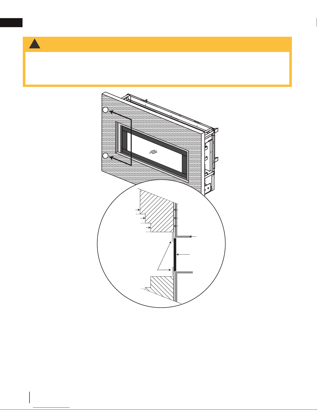
EN
!
WARNING
Door
Top of
appliance
0” (0mm)
4” (101.6mm)
6” (152.4mm)
2” (50.8mm)
5” (127mm)
3”(76.2mm)
Non-combustible facing material must not project more than 4” (101.6mm) from the face of the door (all four
sides). If greater projections are desired, increase the clearance to the sides, bottom and top by 2” (50.8mm) for
every additional 1” (25.4mm) of projection. If using an optional surround, the same rule applies, starting from the
top of the surround. Ensure clearances are maintained for surround removal, as it must lift off the appliance for
maintenance.
B
B
!
WARNING
finishing
10.10 non-combustible facing material
Non-combustible facing material must not project more than 4” (101.6mm) from the face of the door (all four
sides). If greater projections are desired, increase the clearance to the sides, bottom and top by 2” (50.8mm) for
every additional 1” (25.4mm) of projection. If using an optional surround, the same rule applies, starting from the
top of the surround. Ensure clearances are maintained for surround removal, as it must lift off the appliance for
maintenance.
A
A
4”
(101.6mm)
2” (50.8mm)
Optional
surround
6” (152.4mm)
5” (127mm)
4” (101.6mm)
Top of
appliance
Door
42
W415-1285 / G / 04.27.18
Page 43

10.11 hearth pad installation
!
WARNING
note:
The individual hearth pads can be easily identified by the
numbers cast on the underside of each pad.
finishing
B
EN
note:
The pilot is located on the right end in these instructions.
A. Remove the main safety screen and door from the appliance, see
"main safety barrier removal / installation" and "main door removal /
installation" sections for detailed removal instructions.
HINT: For ease of installation, remove both main doors.
B. Place the #3 hearth pad on the pilot side of the burner, as shown in
Figure B.
C. Place the #1A hearth pad on the right side and the #1 hearth pad
on the left side of appliance, as shown in Figure C.
D. Place the two #2 hearth pads on the right and left sides, as shown
in Figure D.
E. Place the #4 hearth pad on the left end, as shown in Figure E.
C
D
E
10.12 log placement
• Failure to position the logs in accordance with these diagrams or failure to use only logs specifi cally approved
with this appliance may result in property damage or personal injury.
• Logs must be placed in their exact location in the appliance. Do not modify the proper log positions, since
appliance may not function properly and delayed ignition may occur.
• The logs are fragile and should be handled with care.
note:
The individual logs can be easily identified by the numbers cast on the underside of each log.
TM
Phazer
is different in every installation. During the initial use of the appliance, log colours may vary. During the initial use of
the appliance, the colours will become more uniform as colour pigments burn in during the heat activated curing
process.
Blocked burner ports can cause an incorrect flame pattern.
1. Remove the main safety screens and doors, see "main safety
2. Place a pin into the bottom of log #1 lining it up with the hole in the
3. Place log #2 onto the pin located in the log #1, it should rest in the
4. Place log #3 onto the pin located in log #2 and let it rest on log #2,
logs and glowing embers, exclusive to Wolf Steel Ltd., provide a unique and realistic glowing effect that
PIN
note:
The pilot is located on the right end in these instructions.
barrier removal / installation" and "main door removal / installation"
sections for removal instructions.
hearth pad. Then place onto the screw and spacer located in the
corner of the burner, on the right side. Place a pin into the center of
log #1 (FIG.1).
middle of the left side hearth pad as shown in Figure 2. Place one
pin into the middle of log #2 (FIG.2).
as shown in Figure 3 and in the left side view below. Place another
pin into log #2 (FIG.3).
PIN
PIN
Fig. 1
Fig. 2
Fig. 3
W415-1285 / G / 04.27.18
43
Page 44
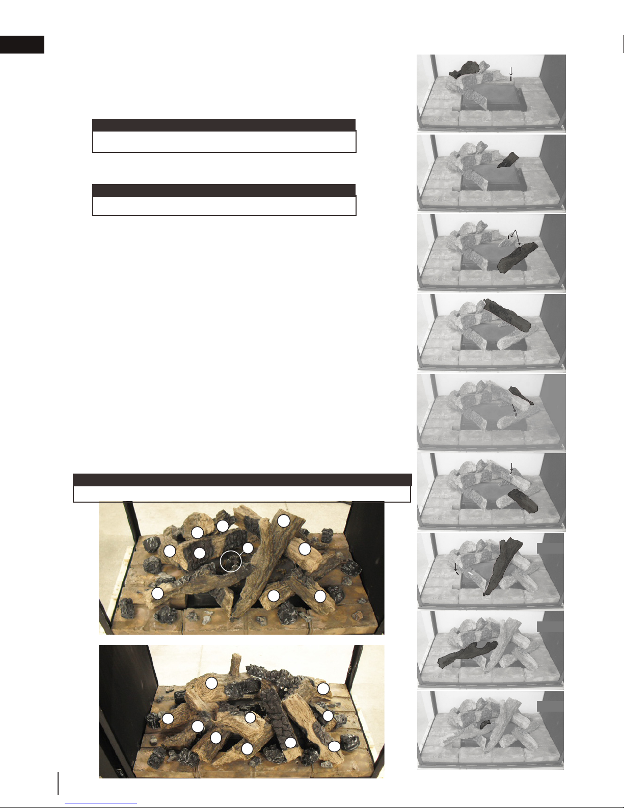
EN
finishing
5. Place log #4 onto the pin located in log #2 and let it rest on log #2, as
6. Place log #5 onto the pin located in the left side hearth pad and let it
7. Place log #6 onto the pin located on the right side corner of the burner,
shown in Figure 4 and in the left side view. Place one pin into the left
side hearth pad (FIG.4).
rest on the burner (FIG.5).
note:
Ensure log #5 does not cover any burner ports.
then place one pin into middle of the log #6 and log #5 (FIG.6).
note:
Ensure log #6 does not cover any burner ports.
PIN
Fig. 4
Fig. 5
8. Place log #7 onto the pin located in log #6 and onto the pin in log #5
(FIG.7).
9. Place log #8 on the hearth pad and let it rest against the notch in the
side of log #7 (FIG.8)
HINT: The best view of log #8 is shown in the left side view below.
10. Place log #9 onto the pin located in log #6 and let it rest on the right
side corner hearth pad and then place one pin into log #7 (FIG.9).
11. Place log #10 onto the pin located in log #7 and let it rest in the middle
of the right side hearth pad, as shown in Figure 10. Place one pin into
log #1 (FIG.10).
12. Place log #11 onto the pin located in log #1 and let it rest on the right
end hearth pad (FIG.11).
13. Place charcoal lump #12 onto the two pins located in the center of the
burner (FIG.12).
14. Install the glowing embers, see "glowing embers" section.
15. Sprinkle the charcoal embers around the log support, see "charcoal
embers" section. (Use illustration below as reference).
16. Place the charcoal lumps on top of the charcoal embers, see "charcoal
lumps" section. (Use illustration below as reference).
note:
Do not cover the pilot or burner ports with media or embers. Do not overfill.
PINS
PIN
PIN
Fig. 6
Fig. 7
Fig. 8
Fig. 9
4
1
2
11
10
6
8
44
W415-1285 / G / 04.27.18
3
12
RIGHT SIDE VIEW
7
5
2
LEFT SIDE VIEW
10
7
6
9
11
1
3
4
PIN
Fig. 10
Fig. 11
Fig. 12
Page 45

10.12.1 glowing embers
Tear the embers into pieces and loosely layer above the burner ports covering the burner area. Care should be
taken to shred the embers into thin, small irregular pieces as only the exposed edges of the fi bre hairs will glow.
The ember material will only glow when exposed to direct fl ame; however, care should be taken to not
block off the burner ports.
Blocked burner ports can cause an incorrect fl ame pattern, carbon deposits and delayed ignition. PHAZER™
logs glow when exposed to direct fl ame. Use only certifi ed “glowing embers” and PHAZER™ logs available from
your local authorized dealer / distributor.
!
WARNING
• Do not block or close off the burner ports. Blocked ports can cause an incorrect fl ame pattern, carbon
deposits and delayed ignition.
Randomly place the charcoal embers along the front and sides of the log support in a realistic manner.
Fine dust found in the bottom of the bag should not be used.
!
WARNING
• Do not block or close off the burner ports. Blocked ports can cause an incorrect fl ame pattern, carbon
deposits and delayed ignition.
• When supplied, charcoal embers, charcoal lumps and vermiculite are not to be placed on the burner.
note:
Charcoal embers are not to be placed on the burner.
Place the lumps in front of the logs in a realistic manner taking care not to block or close off any of the burner ports.
!
WARNING
• Do not block or close off the burner ports. Blocked ports can cause an incorrect fl ame pattern, carbon
deposits and delayed ignition.
• When supplied, charcoal embers, charcoal lumps and vermiculite are not to be placed on the burner.
10.12.2 charcoal embers
finishing
EN
10.12.3 charcoal lumps
W415-1285 / G / 04.27.18
45
Page 46

EN
!
WARNING
finishing
10.13 glass media installation
• Clean the glass media prior to installation. Before applying the cleaned glass, ensure that it is dry.
• Do not change or substitute the glass media material provided with this appliance. If replacing, use only the
replacement glass media available from your local authorized dealer / distributor.
• Glass media over the burner must not be more than one layer high. More than one layer over the burner will
cause fl ame lifting and sooting problems.
• Do not place any media (glass or vermiculite) in or around the pilot opening and/or on the burner ports. This
will interfere with the pilot operation.
Evenly spread the glass media onto the media tray, covering the burner tube and tray. Ensure no glass
media falls into the pilot opening. If this happens, insert a clean bag into your vacuum cleaner and vacuum
out the glass media. Replacement glass can be purchased from your local dealer / distributor.
note:
Do not use more media than what was supplied with the appliance.
Cleaning Glass Media
Glass media may have a fi ne oil residue that needs to be cleaned prior to installation. Clean the glass with
mild dish soap, drain, rinse thoroughly and dry before placing over the burner.
note:
Glass media may cover the entire media tray. Care should be taken around the pilot mesh. We recommend that
no media should be placed directly on the pilot mesh.
BHD4STG AND BHD4PG ONLY
BHD4STFC AND BHD4FC ONLY
MEDIA TRAY
MEDIA TRAY
PILOT MESH
PILOT MESH
46
W415-1285 / G / 04.27.18
Page 47

10.15 logo placement
finishing
EN
1/2”
(13mm)
LOGO
1/2” (13mm)
10.14 anti-condensation switch
note:
End safety barrier must be removed before accessing the anti-condensation switch, see "end safety barrier
removal / installation" section for detailed instructions.
This appliance has the ability to switch from an
electronic intermittent pilot ignition (IPI) to a standing
pilot (ACS) for cold climates. The heat generated by
the standing pilot will improve the start up operation
on colder climate days. Therefore we recommend
switching to the standing pilot on those colder days.
The anti condensation switch (standing pilot) is located
in the control compartment. Using your finger, flip the
switch up for standing pilot, or down for intermittent
pilot ignition.
INSTALLER NOTE:
Some jurisdictions may
prohibit the use of a
standing pilot. In these
jurisdictions the anti
condensation switch
shall be disconnected
to comply with local
codes. To disconnect
locate the white
connector at the end
of the white and blue
wires of the ACS switch
and disconnect.
W415-1285 / G / 04.27.18
47
Page 48

11.0 adjustments
*Maximum inlet pressure not to exceed 13”
This appliance has an air shutter that has been factory set open according to
note:
appropriate kit. This will reduce the velocity of the exhaust gases, slowing down the fl ame pattern and creating a
more traditional gentle fl ame appearance. Specifi c instructions are included with the kit.
EN
adjustments
11.1 pilot burner adjustment
Adjust the pilot screw to provide properly sized fl ame. Turn in a clockwise direction to reduce the gas fl ow.
Check Pressure Readings:
Inlet pressure can be checked by turning screw (A) counterclockwise 2 or 3 turns and then placing pressure gauge tubing
over the test point. Gauge should read as described on the chart
below. Check pressure with main burner operating on “HI”.
Outlet pressure can be checked the same as above using screw
(B). Gauge should read as described on the chart below. Check
pressure with main burner operating on “HI”.
A
B
INSERT PILOT ASSEMBLY
After taking pressure readings, be sure to turn screws
clockwise fi rmly to reseal. Do not overtorque.
Leak test with a soap and water solution.
Prior to pilot adjustment, ensure that the pilot assembly has not been painted. If overspray or painting of
the pilot assembly has occurred remove the paint from the pilot assembly, or replace. Fine emery cloth or a
synthetic scrub pad (such as Scotch-Brite™) can be used to remove the paint from the pilot hood, electrode
and fl ame sensor.
Pressure Natural Gas
(inches)
Inlet
Outlet
*7”
(minimum 4.5”)
3.5” 8.7mb 10” 24.9mb
Natural Gas
(millibars)
17.4mb
(minimum 11.2mb)
Propane
(inches)
13”
(minimum 11”)
(minimum 27.4mb)
PILOT SCREW
Propane
(millibars)
32.4mb
11.2 venturi adjustment
the chart below:
Regardless of venturi orientation, closing the air shutter will cause a more
yellow flame, but can lead to carbonization. Opening the air shutter will cause
a more blue flame, but can cause flame lifting from the burner ports. The flame
may not appear yellow immediately; allow 15 to 30 minutes for the final flame
colour to be established.
AIR SHUTTER ADJUSTMENT MUST ONLY BE DONE BY A QUALIFIED
INSTALLER!
VENTURI
BURNER
ORIFICE
AIR
SHUTTER
OPENING
It is important that the orifice is securely inserted into the venturi.
VENTURI ADJUSTMENT
CHART
NG 1/16” (1.6mm)
P 5/16” (8mm)
11.3 restricting vertical vents
Vertical installations may display a very active fl ame. If this appearance is not desirable, the vent exit must
be restricted using a restrictor vent kit. Refer to the “replacements” section of the owner’s manual for the
note:
If the appliance has been reduced to 4/7" venting only, use an RP4 to restrict vertical venting.
48
W415-1285 / G / 04.27.18
Page 49

11.4 flame characteristics
It’s important to periodically perform a visual check of
the pilot and burner flames. Compare them to the
illustration provided. If any flames appear abnormal,
call a service person.
LOG BURNER
3/8” - 1/2”
(9.5mm - 12.7mm)
ELECTRODE
ADD IMAGE
HERE
FLAME MUST ENVELOP
UPPER 3/8” (9.5mm) TO 1/2”
(12.7mm) OF FLAME SENSOR
adjustments
FLAME SENSOR
PILOT
BURNER
EN
GLASS BURNER
CRADLE
W415-1285 / G / 04.27.18
49
Page 50

EN
WARNING
12.0 maintenance
maintenance
!
• Turn off the gas and electrical power before servicing the appliance.
• Appliance may be hot. Do not service until appliance has cooled.
• Do not use abrasive cleaners on glass.
• Do not paint the pilot assembly.
This appliance and its venting system should be inspected before use and at least annually by a qualifi ed
service person. The following suggested checks should be performed by a qualifi ed technician. The appliance
area must be kept clear and free of combustible materials, gasoline, or other fl ammable vapors and liquids.
The fl ow of combustion and ventilation air must not be obstructed.
note:
Caution: Label all wires prior to disconnection when servicing controls. Wiring errors can cause improper and
dangerous operation. Verify proper operation after servicing.
1. In order to properly clean the burner and pilot assembly, remove the logs, rocks and/or glass to ex-
pose both assemblies.
2. Keep the control compartment, media, burner, air shutter opening and the area surrounding the appli-
ance clean by vacuuming or brushing, at least once a year.
3. Check to see that all burner ports are burning. Clean out any of the ports which may not be burning
or are not burning properly.
4. Check to see that the pilot fl ame is large enough to engulf the fl ame sensor and/or thermocouple /
thermopile as well as it reaches the burner.
5. If your appliance is equipped with a safety barrier, cleaning may be necessary due to excessive lint /
6. If your appliance is equipped with relief doors, ensure the system performs effectively. Check that the
7. Replace the cleaned logs, rocks or glass. Failure to properly position the media may cause carboning
8. Check to see that the main burner ignites completely on all ports when turned on. A 5 to 10 second
9. Visually inspect the appliance for carbon build up. Using a small whisk or brush, brush off the carbon
10. This step is not applicable for Vent Free appliances: Check to see that the appliance is vent-
dust from carpeting, pets, etc. simply vacuum using the brush attachment.
gasket is not worn or damaged. Replace if necessary.
which can be distributed in the surrounding living area, inside the fi rebox and on exterior surfaces surrounding vent termination.
total light-up period is satisfactory. If ignition takes longer, consult your local authorized dealer / distributor.
and vacuum up or sweep into garbage.
ing correctly. Ensure chimney system is safe and unobstructed. (If for any reason the vent air intake
system is disassembled, re-install and re-seal per the instructions provided for the initial installation).
50
W415-1285 / G / 04.27.18
Page 51

maintenance
WARNING
appliance manufacturer. DO NOT SUBSTITUTE MATERIALS.
12.1 care of glass
!
• Do not clean glass when hot! Do not use abrasive cleaners to clean glass.
Buff lightly with a clean dry soft cloth to remove accumulated dust or fi ngerprints. Clean both sides of the glass
after the fi rst 10 hours of operation with an ammonia-free glass cleaner.
note:
Vinegar-based glass cleaners have demonstrated an ability to provide a clean, streak free glass surface.
Thereafter, clean as required. If the glass is not kept clean permanent discoloration and / or blemishes may
result. Contact you local authorized dealer / distributor for complete cleaning instructions.
Razor blades, steel wool, or other metallic objects must not be used on both surfaces of the glass. Doing so
can remove a thin layer of metal from the razor blades, steel wool, or other metallic objects that may then be
deposited onto the coating. This can result in a discoloured stain or scratch-like mark. More importantly, this can
scratch the glass surface, thereby reducing its strength.
Do not operate the appliance with broken glass, as leakage of fl ue gases may result.
Contact your local authorized dealer / distributor for complete cleaning instructions.
If the glass should ever crack or break while the fi re is burning, do not open the door until the fi re is out. Do not
operate the appliance until the glass has been replaced. Contact you local authorized dealer / distributor for
replacement parts. DO NOT SUBSTITUTE MATERIALS.
EN
This appliance is factory equipped with 5mm tempered glass. Use only replacement parts as supplied by the
W415-1285 / G / 04.27.18
51
Page 52
EN
WARNING
WARNING
Replacement glass/frame assembly shall be replaced as a complete unit as supplied by the appliance
maintenance
12.2 annual maintenance
!
• Annual maintenance should be performed by a qualifi ed service technician
• The fi rebox becomes very hot during operation. Let the appliance cool completely or wear heat resistant
gloves before conducting service.
• Never vacuum hot embers.
• Do not paint the pilot assembly
• This appliance will require maintenance which should be planned on an annual basis.
• Service should include cleaning, battery replacement, venting inspection and inspection of the burner,
media, and fi rebox. Refer to the door removal section and remove the door as instructed.
• Carefully remove media if necessary (logs, glass, brick panels, etc.).
• Using a vacuum with soft brush attachment, gently remove any dirt, debris, or carbon build up from the
logs, fi rebox, and burner. For glass media, follow the installation instructions for pre-cleaning.
• Gently remove any build-up on the pilot assembly including thermopile, thermocouple, fl ame sensor, and
igniter (if equipped).
note:
Clean fl ame sensor using a fi ne emery cloth or a synthetic scrub pad (such as Scotch-Brite™) to remove any
oxides. Clean the pilot assembly using a vacuum with a soft brush attachment. It is important that the pilot
assembly is not painted.
• Inspect all accessible gaskets and replace as required.
• If equipped with a blower, access the blower and clean using a soft brush and vacuum.
• Re-assemble the various components in reverse order.
• Inspect the relief system. The appliance relieves through the main glass door or through the fl aps on the
fi rebox top. Ensure they open freely, and close sealed.
• Check the gas control valve pilot and Hi / Lo knobs move freely, if equipped. Replace if any stiffness in
movement is experienced.
• Check for gas leaks on all gas connections up and downstream from the gas valve including pilot tube
connections.
12.3 glass / door replacement
!
• Do not use substitute materials.
• Glass may be hot. Do not touch glass until cooled.
• Care must be taken when removing and disposing of any broken door glass or damaged components. Be
sure to vacuum up any broken glass from inside appliance before operation.
• Do not strike, slam, or scratch. Do not operate appliance with glass removed, cracked, broken, or scratched.
manufacturer.
52
W415-1285 / G / 04.27.18
Page 53

maintenance
12.4 burner removal
12.4.1 log burner removal
A. Remove the main door(s) from the appliance see "main door removal / installation" section for detailed
removal instructions.
B. Carefully remove the charcoal embers, charcoal lumps, glowing embers and logs from the appliance.
C. Remove all of the hearth pads, from the appliance. Refer to the "hearth pad installation / removal" section
for instructions.
D. Remove the 4 screws securing the burner in place. Then slide the burner off the orifice and remove from
the appliance.
E. To reinstall the burner, reverse these steps.
note:
When reinstalling the burner, ensure that the venturi rest on the orifice.
EN
12.4.2 glass burner removal
A. Remove the main door(s) from the appliance see "main door removal / installation" section for detailed
removal instructions.
B. Vacuum the glass media out of the appliance. Ensure you insert a clean bag into your vacuum cleaner.
C. Remove the 12 screws securing the media tray, then remove the media tray from the appliance, as shown
below.
D. Remove the 4 screws securing the burner, as shown below. Then slide the burner off of the orifice and
remove from the appliance.
E. To reinstall the burner reverse these steps.
note:
When reinstalling the burner, ensure that the venturi rest on the orifice.
C
D
W415-1285 / G / 04.27.18
53
Page 54

EN
maintenance
12.4.3 cradle burner removal
A. Remove the door(s) refer to the "door removal / installation" section for instructions.
B. Carefully remove the glass or rocks from the appliance.
C. To remove the media bowl support from the appliance, lift the media bowl and the media bowl support up
and out of the appliance. The media bowl support and media bowl are secured together and resting loose
in the firebox.
D. Remove the 4 screws securing the burner in place, as shown below. Then slide the burner off the orifice
and remove from the appliance.
E. To reinstall the burner reverse these steps.
note:
When reinstalling the burner, ensure that the venturi rest on the orifice.
C
MEDIA
BOWL
MEDIA BOWL
SUPPORT
D
12.5 valve train replacement
A. Remove the safety screen and main door(s). See "main safety barrier removal / installation" and "main
door removal / installation" sections for detailed removal instructions.
B. Remove the burners, see "burner removal" section.
C. Remove the 12 screws holding the valve train in place, as shown below.
note:
A new gasket may be required when reinstalling the valve train assembly. Contact your local
authorized dealer/distributor.
D. Carefully lift the valve train assembly out far enough to access the manual shut off valve and turn to the
off position. Disconnect the flex connector from the valve. You may now lift the valve train out of the
appliance.
54
W415-1285 / G / 04.27.18
Page 55

13.0 replacements
WARNING
replacements
!
• Failure to position the parts in accordance with this manual or failure to use only parts specifi cally approved
with this appliance may result in property damage or personal injury.
• **This is a fast acting thermocouple. It is an integral safety component. Replace only with a fast acting supplied
by Wolf Steel Ltd.
Contact your dealer for questions concerning prices and policies on replacement parts. Normally, all parts can
be ordered through your Authorized dealer / distributor.
For warranty replacement parts, a photocopy of the original invoice will be required to honour the
claim.
When ordering replacement parts always give the following information:
• Model & Serial Number of appliance
• Installation date of appliance
• Part number
• Description of part
• Finish
Parts, part numbers, and availability are subject to change without notice.
Parts identifi ed as stocked will be delivered within 2 to 5 business days for most delivery
destinations.
Parts not identifi ed as stocked will be delivered within a 2 to 4 week period, for most cases.
Parts identifi ed as ‘SO’ are special order and can take up to 90 days for delivery
EN
W415-1285 / G / 04.27.18
55
Page 56

EN
X4
GL-686
Description
142
5
cradle burner assembly” section.
9
24
25
15
192220
(RS) Control panel assembly
Door gasket assembly
Stocked
Main door assembly
Main door safety barrier
Yes
Safety
screen
Safety screen
Yes
Yes
W333-0024
W333-0023
W010-3481
W010-2997
W010-3208-SER
W080-1395
ACS switch bracket
W750-0191
ACS switch
W707-0010
Transformer
W010-2829
For replacement parts, refer to:
“glass burner assembly” section.
For replacement parts, refer to:
“log / cradle burner valve train assembly” section.
For replacement parts, refer to:
“glass burner valve train assembly” section.
Yes
Yes
Yes
Yes
Yes
Yes
Yes
Yes
Yes
15
Notched hearth pad #3 (GL-686)
Yes
replacements
13.1 BHD4P overview
56
W415-1285 / G / 04.27.18
Page 57

replacements
X4
GL-686
Description
142
5
20
21
11
Items may not appear exactly as illustrated
Control access panel
Door gasket assembly
Stocked
Main door assembly
Main door safety barrier
Yes
Safety screen
W333-0023
W010-3481
W010-2997
W080-1395
ACS switch bracket
W750-0191
ACS switch
W707-0010
Transformer
W010-2829
Yes
Yes
For replacement parts, refer to: “log /
cradle burner assembly” section.
For replacement parts, refer to:
“glass burner assembly” section.
For replacement parts, refer to:
For replacement parts, refer to:
“glass burner valve train assembly” section.
Yes
Yes
Yes
Yes
Yes
Yes
Yes
12
Yes
EN
13.2 BHD4ST overview
W415-1285 / G / 04.27.18
57
Page 58

EN
414
1
11.09.16
Description
1
W010-2954-SER
2
W080-1400-SER
Burner bracket
W290-0018
Venturi gasket
4
W720-0005
Venturi
Yes
Items may not appear exactly as illustrated.
Yes
replacements
13.3 glass burner assembly
58
W415-1285 / G / 04.27.18
Page 59

replacements
6
7
Ref. No.
Part number
Description
W432-0103
Gas manifold
W456-0037
Burner orifice #37 (NG)
Description
Pilot shield
W010-3024
Pilot assembly (NG)
Stocked
Yes
Stocked
Yes
Items may not appear exactly as illustrated
W290-0157
Manifold gasket
W105-0001
Bushing
Yes
W010-1985
Wire harness assembly
W190-0072
Control board
W080-1366
Valve bracket
W725-0065
Valve (NG)
Yes
Yes
Yes
W725-0066
Valve (P)
Yes
W456-0052
Burner orifice #52 (P)
Yes
Valve train base
Valve access cover
Valve access gasket
Yes
Yes
Yes
EN
13.4 glass burner valve train assembly
W415-1285 / G / 04.27.18
59
Page 60

EN
2
4
5
2
4
5
11.09.16
Part number
W010-2955
Burner assembly
W080-1463
Burner bracket
W290-0018
Venturi gasket
4
Venturi
5
Burner bracket
Yes
Ref. No.
Stocked
Items may not appear exactly as illustrated
Yes
replacements
13.5 log / cradle burner assembly
60
W415-1285 / G / 04.27.18
Page 61

replacements
7
10
13
8
9
12
11811
14
9
10
13
12
Ref. No.
Part number
1
W432-0103
2
W456-0037
9
10
Stocked
Yes
Stocked
Yes
131216
15
Yes
W080-1372
Pilot bracket
11
W035-0338
Valve train base
12
W200-0456
Valve access cover
13
W290-0247
Access gasket
Yes
151614
10
Yes
Yes
Valve bracket
Valve (NG)
Yes
8
W725-0066
Valve (P)
Yes
W456-0052
Yes
Yes
Yes
EN
13.6 log / cradle burner valve train assembly
W415-1285 / G / 04.27.18
61
Page 62

EN
A4758AK
Ref. No.
Front side view
Rear side view
W500-0706-BK2GL
W475-0871
15
1617181314
8
2
2
2
24
1098
2
2
92
93
LDAC
Designer fire art coil design
Amber glass embers (1lb)
Topaz glass embers (1lb)
PRPHD4
19
21
192021
Yes
Yes
Yes
Yes
Yes
Yes
Yes
Yes
Yes
Yes
Yes
Yes
Yes
Yes
9
22
replacements
14.0 accessories
62
W415-1285 / G / 04.27.18
Page 63

15.0 troubleshooting
WARNING
TUBE DE LA
VEILLEUSE
INJECTEUR
troubleshooting
!
• Always light the pilot whether for the fi rst time or if the gas supply has run out, with the glass door open or
removed.
• Turn off gas and electrical power before servicing the appliance.
• Appliance may be hot. Do not service until appliance has cooled.
• Do not use abrasive cleaners
symptom problem test solution
Main burner fl ame is a
blue, lazy, transparent
fl ame.
(This is not applicable
in outdoor appliances)
Flames are consistently
too large or too small.
Carboning occurs.
INSERT
PHOTO
OF VALVE
HERE
Blockage in vent. - Remove blockage. In really cold conditions, ice buildup may occur
Incorrect installation. - Refer to “venting” section to ensure correct installation.
Appliance is over-fi red or underfi red.
INJECTOR
PILOT TUBE
FITTING
Pressure Natural Gas
Inlet
(minimum 4.5”)
Outlet
on the terminal and should be removed as required. (To minimize this
from reoccuring, the vent lengths that pass through unheated spaces
(attics, garages, crawl spaces) be wrapped with an insulated mylar
sleeve).
- Check pressure readings:
Inlet pressure can be checked by turning screw (A) counter-clockwise 2 or 3 turns and then placing pressure gauge tubing over the
test point. Gauge should read as described on the chart below.
Check that main burner is operating on ‘HI’. Outlet pressure can be
checked the same as above using screw (B). Gauge should read as
described on the chart below. Check that main burner is operating
on ‘HI’. After taking pressure readings, be sure to turn screws
clockwise fi rmly to reseal. DO NOT OVER TORQUE.
Leak test with a soap and water solution.
(inches)
*7”
3.5” 8.7mb 10” 24.9mb
Natural Gas
(millibars)
17.4mb
(minimum 11.2mb)
*Maximum inlet pressure not to exceed 13”
Propane
(inches)
13”
(minimum 11”)
EN
Propane
(millibars)
32.4mb
(minimum 27.4mb)
Air shutter improperly adjusted.
Carbon is being
deposited on glass,
logs, rocks, media, or
combustion chamber
surfaces.
White / grey fi lm forms. Sulphur from fuel is being depos-
Exhaust fumes smelled
in room, headaches.
Air shutter is blocked. - Ensure air shutter opening is free of lint or other obstructions.
Flame is impinging on the glass,
logs, rocks, media or combustion chamber.
ited on glass, logs, or combustion chamber surfaces.
Appliance is spilling.
(This is not applicable in outdoor
appliances).
- Return air shutter to specifi ed opening, see “venturi adjustments”
section in the installation manual.
- Ensure the media is positioned correctly in the appliance.
- Open air shutter to increase the primary air.
- Check the input rate: check the manifold pressure and orifi ce size as
specifi ed by the rating plate.
- Ensure door gaskets are not broken or missing and the seal is tight.
- Ensure vent liners are free of holes and well sealed at all joints.
- Check that minimum rise per foot (meters) has been adhered to for
any horizontal venting.
- Clean the glass with a recommended gas fi replace glass cleaner. DO
NOT CLEAN GLASS WHEN HOT.
- If deposits are not cleaned off regularly, the glass may become
permanently marked.
- Check door seal.
- Check for exhaust damage.
- Check that venting is installed correctly.
- Room is in negative pressure; increase fresh air supply.
W415-1285 / G / 04.27.18
63
Page 64

in room, headaches.
(This is not applicable in outdoor
appliances).
- Check for exhaust damage.
- Check that venting is installed correctly.
- Room is in negative pressure; increase fresh air supply.
EN
troubleshooting
symptom problem test solution
Pilot will not light. Makes
noise with no spark at
pilot burner.
Pilot sparks but will
not light.
Burner continues to
spark and pilot lights
but main burner
does not light.
Remote wall switch
is in “off” position;
burner comes on.
Remote and / or
receiver is not
functioning properly.
Wiring: short, loose, or damaged
connections
(poor fl ame rectifi cation).
No signal from remote with no
pilot ignition.
Poor grounding. - Verify the valve and pilot assembly is properly grounded
Improper switch wiring.
Dirty, painted, or damaged pilot
and/or dirty sensor rod.
- Verify the thermocouple/sensor is clean and the wiring is undamaged.
- Verify the interrupter block is not damaged or too tight. Verify
connections from pilot assembly are tight; also verify the connections
are not grounding out to any metal. (Remember, the fl ame carries the
rectifi cation current, not the gas. If fl ame lifts from pilot hood, the circuit
is broken. A wrong orifi ce or too high of an inlet pressure can cause the
pilot fl ame to lift)*. The sensor rod may need cleaning.
- Reprogram receiver code.
- Replace receiver.
- Troubleshoot the system with the simplest on/off switch.
- Clean sensor rod with a green Scotch-Brite™ pad to remove any
contamination that may have accumulated. Verify continuity with
multimeter with ohms set at the lowest range.
Gas supply. - Verify that the incoming gas line ball valve is “open”.
- Verify that the inlet pressure reading is within acceptable
limits, inlet pressures must not exceed 14” W.C. (34.9mb).
Out of propane gas. - Fill the tank.
Pilot supply line may contain
air.
- Repeat ignition process several times or purge the pilot
supply line.
Incorrect wiring / grounding. - Ensure correct polarity of wiring of thermocouple (if
equipped).
- Verify pilot assembly/valve are properly grounded.
Receiver (if equipped). - Reset program: hold reset button on receiver and wait for 2
beeps. Release after second beep. Press small fl ame button
on remote within 20 seconds, you will hear an additional
beep (this signals a successful reset).
- Replace receiver.
Valve. - Check valve and replace if necessary (Do not to overtighten
thermocouple).
Short or loose connection in
sensor rod.
- Verify all connections. Verify the connections from the pilot
assembly are tight. Also, verify these connections are not
grounding out to any metal.
Dirty, painted, or damaged
pilot assembly components.
- Clean using a green Scotch-Brite™ pad to remove any
contamination that may have accumulated on the sensor
rod, pilot hood, ignitor, or fl ame sensor. Verify continuity with
multimeter with ohms set at the lowest range.
Wall switch mounted upside
- Reverse.
down.
Remote wall switch and/or
wire is grounding.
- Replace.
- Check for ground (short); repair ground or replace wire.
Faulty wire - Replace.
Remote controls lights but
no spark or fl ame. (Remote is
locked out).
- Reset by turning power source off then on.
note:
If back up batteries are installed, they must also be removed to
re-program
Receiver or remote has low battery.
Appliance functions but does not
respond to receiver / remote
Error with synchronizing. - Reset receiver and remote.
Remote too far away from receiver.
Wire connector pins are bent. - Straighten pins.
Valve wiring is damaged. - Replace valve.
64
W415-1285 / G / 04.27.18
- Replace batteries.
- Ensure appliance is being operated by the same device that turned it
on. Remote controls functions if appliance was turned on by remote.
Receive controls functions if appliance was turned on by receiver.
- Refer to “wiring diagram” section.
Page 65

rod, pilot hood, ignitor, or fl ame sensor. Verify continuity with
multimeter with ohms set at the lowest range.
Remote wall switch
is in “off” position;
burner comes on.
Wall switch mounted upside
down.
- Reverse.
Remote wall switch and/or
wire is grounding.
- Replace.
- Check for ground (short); repair ground or replace wire.
Faulty wire - Replace.
Remote and / or
receiver is not
functioning properly.
Remote controls lights but
no spark or fl ame. (Remote is
locked out).
- Reset by turning power source off then on.
Receiver or remote has low battery.
- Replace batteries.
Appliance functions but does not
respond to receiver / remote
- Ensure appliance is being operated by the same device that turned it
on. Remote controls functions if appliance was turned on by remote.
Receive controls functions if appliance was turned on by receiver.
Error with synchronizing. - Reset receiver and remote.
Remote too far away from receiver.
- Refer to “wiring diagram” section.
Wire connector pins are bent. - Straighten pins.
Valve wiring is damaged. - Replace valve.
If back up batteries are installed, they must also be removed to
re-program
note:
Motor is turning,
frequent beeping
occurs.
Lights or blower
won’t function (if
equipped).
Flames are very
aggressive.
Appliance won’t perform any functions.
symptom problem test solution
Receiver batteries low. - Replace batteries.
Control module switch in
wrong position.
COM switch is unplugged. - Verify “COM” switch is plugged into the front of the control
Door is ajar. - Ensure door is secured properly.
Venting action is too great. - Check to ensure venting is properly sealed or restrict vent
No power to the system.
Receiver switch in wrong
position (if equipped).
Transmitter isn’t operational. - Check battery power and battery orientation.
troubleshooting
- Verify ON/OFF switch is in the “I” position which denotes on.
module.
exit with restrictor plate. (Not available in all appliances).
- Check breaker to verify it’s in the “on” position.
- Verify that the 3 position switch on the receiver is in the
remote position (middle).
EN
symptom problem test solution
The following applies specifi cally to the SIT system only:
Pilot will not light.
Makes no noise with
no spark at pilot
burner. (Lights and
blower operate, if
equipped).
note:
Starting from off, press the on button on the transmitter. Approximately 4 seconds on/off button is pressed, the ignition
board will start the spark. The fi rst try for ignition will last approximately 60 seconds. If there is no fl ame ignition (rectifi cation),
the board will stop sparking for approximately 35 seconds. After the wait time, the board will start the second try for ignition
by sparking for approximately 60 seconds. If there is still no positive ignition, the board will go into lock out.
Ignition box has been locked
out.
Choose one of the 4 methods below to reset the system.
1. To reset ignition box when locked out. Turn off power supply
and remove batteries (if used) from the back up battery pack.
2. To reset the DFC Board when the board goes into a lock
out condition and the LED is blinking 3 times using the
transmitter on/off button:
Step 1: Turn the system off by pressing the on/off
button to turn the system off.
Step 2: After approximately 2 seconds press the on/
off button on the transmitter again. The DFC Board will
reset and the ignition sequence will start again.
3. To reset the DFC Board when the board goes into a lock out
condition and the LED is blinking 3 times by cycling fl ame:
Step 1: In the manual fl ame control mode, use the down
arrow button to reduce the fl ame to off, indicated by the
word OFF displayed on the transmitter LCD screen.
Step 2: Wait approximately 2 seconds and press the up
arrow button, the ignition sequence will start.
W415-1285 / G / 04.27.18
65
Page 66

EN
Napoleon warrants its products against manufacturing defects to the original purchaser only. Registering your warranty is
not necessary. Simply provide your proof of purchase along with the model and serial number to make a warranty claim.
Napoleon reserves the right to have its representative inspect any product or part thereof prior to honouring any warranty
claim. Provided that the purchase was made through an authorized Napoleon dealer your appliance is subject to the
following conditions and limitations:
Warranty coverage begins on the date of original installation. This factory warranty is non-transferable and may not
be extended whatsoever by any of our representatives. The gas appliance must be installed by a licensed, authorized
service technician or contractor qualifi ed and authorized installer, service agency or supplier. Installation must be done in
accordance with the installation instructions included with the product and all local and national building and fi re codes.
This limited warranty does not cover damages caused by misuse, lack of maintenance, accident, alterations, abuse or
neglect, and parts installed from other manufacturers will nullify this warranty. This limited warranty further does not cover
any scratches, dents, corrosion or discoloring caused by excessive heat, abrasive and chemical cleaners nor chipping
on porcelain enamel parts, mechanical breakage of Phazer™ logs and embers. This warranty extends to the repair or
replacement of warranted parts which are defective in material or workmanship provided that the product has been
operated in accordance with the operation instructions and under normal conditions. After the fi rst year, with respect to
this President’s Lifetime Limited Warranty, Napoleon may, at its discretion, fully discharge all obligations with respect to this
warranty by refunding to the original warranted purchaser the wholesale price of any warranted but defective part(s).
Napoleon will not be responsible for installation, labour, or any other expenses related to the reinstallation of a warranted
part and such expenses are not covered by this warranty. Notwithstanding any provisions contained in the President’s
Lifetime Limited Warranty, Napoleon’s responsibility under this warranty is defi ned as above and it shall not in any event
extend to any incidental, consequential or indirect damages. This warranty defi nes the obligations and liability of Napoleon
with respect to the Napoleon gas appliance and any other warranties expressed or implied with respect to this product,
its components or accessories are excluded. Napoleon neither assumes, nor authorizes any third party to assume, on
its behalf, any other liabilities with respect to the sale of this product. Napoleon will not be responsible for: over-fi ring,
downdrafts, spillage caused by environmental conditions such as rooftops, buildings, nearby trees, hills, mountains,
inadequate vents or ventilation, excessive venting confi gurations, insuffi cient makeup air, or negative air pressures which
may or may not be caused by mechanical systems such as exhaust fans, furnaces, clothes dryers, etc. Any damages to
the appliance, combustion chamber, heat exchanger, plated trim or other components due to water, weather damage, long
periods of dampness, condensation, damaging chemicals or cleaners will not be the responsibility of Napoleon. All parts
replaced under the President’s Limited Lifetime Warranty Policy are subject to a single claim.
During the fi rst 10 years Napoleon will replace or repair the defective parts covered by the lifetime warranty at our discretion
free of charge. From 10 years to life, Napoleon will provide replacement parts at 50% of the current retail price. All parts
replaced under the warranty will be covered for a period of 90 days from the date of their installation. The manufacturer
may require that defective parts or products be returned or that digital pictures be provided to support the claim. Returned
products are to be shipped prepaid to the manufacturer for investigation. If a product is found to be defective, the
manufacturer will repair or replace such defect. Before shipping your appliance or defective components, your dealer must
obtain an authorization number. Any merchandise shipped without authorization will be refused and returned to sender.
Shipping costs are not covered under this warranty. Additional service fees may apply if you are seeking warranty service
from a dealer. Warranty labour allowance is only for the replacement of the warranted part. Travel, diagnostic tests, shipping
and other related charges are not covered by this warranty.
Napoleon products are manufactured under the strict Standard of the world recognized ISO 9001 : 2015 Quality Management
System.
Napoleon products are designed with superior components and materials assembled by trained craftsmen who take great
pride in their work. The burner and valve assembly are leak and test-fi red at a quality test station. The complete appliance is
again thoroughly inspected by a qualifi ed technician before packaging to ensure that you, the customer, receives the quality
product that you expect from Napoleon.
The following materials and workmanship in your new Napoleon gas appliance are warranted against defects for as long
as you own the appliance. This covers: combustion chamber, heat exchanger, stainless / steel burner, Phazer™ logs
and embers, rocks, ceramic glass (thermal breakage only), gold plated parts against tarnishing, porcelainized enameled
components and aluminum extrusion trims.*
Electrical (110V and millivolt) components and wearable parts are covered and Napoleon will provide replacement parts free
of charge during the fi rst year of the limited warranty. This covers: blowers, gas valves, thermal switches, switches, wiring,
remote controls, ignitors, gaskets and pilot assemblies.*
Labour related to warranty repair is covered free of charge during the fi rst year (labour warranty is not applicable for the
Gas Log Sets). Repair work, however, requires the prior approval of an authorized company offi cial. Labour costs to the
account of Napoleon are based on a predetermined rate schedule and any repair work must be done through an authorized
Napoleon dealer.
* Construction of models vary. Warranty applies only to components included with your specifi c appliance.
Napoleon Gas Appliance President’s Lifetime Limited Warranty
Conditions and Limitations
All specifi cations and designed are subject to change without prior notice due to on-going product improvements. Napoleon is a registered
trademark of Wolf Steel Ltd.
warranty
16.0 warranty
66
W415-1285 / G / 04.27.18
Page 67

17.0 service history
service history
EN
Appliance Service History
This appliance must be serviced annually depending on usage.
Date Dealer Name Service Technician Name Service Performed Special Concerns
W415-1285 / G / 04.27.18
67
Page 68

NAPOLEON CELEBRATING OVER 40 YEARS
OF HOME COMFORT PRODUCTS
7200, Route Transcanadienne, Montréal, Québec H4T 1A3
24 Napoleon Road, Barrie, Ontario, Canada L4M 0G8
214 Bayview Drive, Barrie, Ontario, Canada L4N 4Y8
103 Miller Drive, Crittenden, Kentucky, USA 41030
Phone: 1-866-820-8686
napoleonproducts.com
Page 69

MODÈLES DE GAZ NATUREL
BHD4PN / BHD4STN / BHD4PGN / BHD4STGN / BHD4PFCN / BHD4STFCN
ADD PRODUCT CODE HERE (TRADE GOTHIC LT STD FONT)
MODÈLES DE PROPANE
BHD4PP / BHD4STP / BHD4PGP / BHD4STGP / BHD4PFCP / BHD4STFCP
MANUEL D'INSTALLATION
CONSIGNES DE SÉCURITÉ
AVERTISSEMENT!
RISQUE D’INCENDIE OU D’EXPLOSION
Incapacité à suivre ces avertissements
exactement peuvent entraîner de grave
blessures, des pertes de vie ou des
dommages matériels.
- N’entreposez pas et n’utilisez pas d’essence
ou autres liquides et vapeurs infl ammables à
proximité de cet appareil ou tout autre appareil.
- QUE FAIRE SI VOUS DÉTECTEZ UN
ODEUR DE GAZ:
• N’allumez aucun appareil.
• Ne touchez à aucun interrupteur
électrique; n’utilisez aucun téléphone dans
votre immeuble.
• Appelez immédiatement votre fournisseur
de gaz d’un téléphone voisin. Suivez ses
instructions.
• Si vous ne pouvez pas rejoindre votre
fournisseur de gaz, appelez le service des
incendies.
- L’installation et l’entretien doivent être faits par
un installateur qualifi é, une agence d’entretien
ou le fournisseur.
FRANÇAIS
ADD MANUAL TITLE
ET D'OPÉRATION
AscentMD Multiface
ÉCRAN DE PROTECTION
ADD PRODUCT IMAGE
BHD4ST ILLUSTRÉ
Product Name / Code
(see price book)
(BHD4ST illustré)
ADD ____ ILLUSTRATED
Cet appareil peut être installé dans une maison
préfabriquée (mobile) déjà installée à demeure
si les règlements locaux le permettent.
Cet appareil doit être utilisé uniquement
avec le type de gaz indiqué sur la plaque
d’homologation. Cet appareil ne peut être
converti à d’autres gaz, sauf si une trousse de
conversion est utilisée.
INSTALLATEUR:
Laissez ce manual avec l’appareil
PROPRIÉTAIRE:
Conservez ce manuel pour consultation
ultérieure
Wolf Steel Ltd., 24 Napoleon Rd., Barrie, ON, L4M 0G8 Canada / 103 Miller Drive, Crittenden, Kentucky, USA, 41030
Téléphone 1(866)820-8686 • www.napoleonfoyers.com • hearth@napoleonproducts.com
$10.00
POUR USAGE INTÉRIEUR SEULEMENT
CERTIFIÉ SELON LES NORMES NATIONALES CANADIENNES ET AMÉRICANES:
CSA 2.22 ET ANSI Z21.50 POUR LES APPAREILS À GAZ DÉCORATIF À ÉVACUATION
IF INSTALLATION + OPERATION, ADD SERIAL
CSA /
INTERTEK
LOGO
IF SEPARATE MANUALS, ADD “PLACE
BARCODE LABEL ON THE OWNER’S MANUAL”
NUMBER LABEL HERE
W415-1285 / G / 04.27.18
Page 70

consignes de sécurité
HOT GLASS WILL CAUSE
BURNS.
DO NOT TOUCH GLASS UNTIL
COOLED.
NEVER ALLOW CHILDREN TO
TOUCH GLASS.
!
DANGER
AVERTISSEMENT
A barrier designed to reduce the risk of burns from the
hot viewing glass is provided with this appliance and
shall be installed for the protection of children and other
at-risk individuals.
!
AVERTISSEMENT
FR
• Cet appareil est chaud lorsqu’il
fonctionne et peut causer de graves
brûlures en cas de contact.
• Toute modifi cation apportée à cet
appareil ou aux contrôles peut être
dangereux et est interdit.
• Ne faites pas fonctionner l’appareil avant
d’avoir lu et compris les instructions
d’opération. Omettre d’utiliser l’appareil selon
les instructions d’opération pourrait causer un
incendie ou des blessures.
• S’assurez que la porte vitrée est ouvert ou
retiré de l’appareil lorsque vous allumer le
pilote pour la première fois et lorsque le gaz est
épuisé
• Risque d’incendie ou d’asphyxie ne faites pas
fonctionner l’appareil avec la vitre retirée et
jamais obstruer l’ouverture sur le devant de l’appareil.
• Les objets doivent être gardés à une distance d’au moins 4 pieds (1.22m) du devant de l’appareil.
• Ne branchez pas la soupape à du courant 110 volts, avec les exception de modèles; GSST8 et GT8.
• Risque de brûlures. L’appareil doit être éteint et refroidi avant d’effectuer un entretien.
• N’installez pas de composants endommagés ou incomplets ni des composants substituts.
• Risque de coupures et d’érafl ures. Portez des gants protecteurs et des lunettes de sécurité lors de
l’installation. Les bordures des pièces de métal peuvent être coupantes.
• Ne brûlez pas de bois ou autres matériaux dans cet appareil.
• Assurez-vous d’une quantité suffi sante d’air de combustion et de ventilation. Prévoyez un accès suffi sant
pour entretenir et opérer l’appareil. N’obstruez jamais l’ouverture sur le devant de l’appareil.
• L’appareil doit être gardé libre de tous matériaux combustibles, essence ou autres liquides et vapeurs
infl ammables.
• Haute pression endommagera la soupape. Débrancher la tuyauterie d’alimentation en gaz avant de tester la pression
de ligne de gaz à la pression d’essai au-dessus de 1/2 psig. Fermer l’arrêt manuelle du soupape avant de tester la
pression de ligne de gaz à la pression égale ou inférieure à 1/2psig (35mb).
• L’appareil ne doit pas être utilisé au températures au-dessous de zero (32°f / 0°c). Permettre à l’appareil
pour réchauffer au-dessus de zero avant le fonctionnement, avec l’exception de modèles; GSS36,
GSS42; ces appareil sont adaptés pour 0°F / -18°C.
• Les enfants et les adultes devraient être informés des dangers que posent les températures
de surface élevées et se tenir à distance afin d’éviter des brûlures ou que leurs vêtements ne
s’enflamment.
• Les jeunes enfants doivent être surveillés attentivement lorsqu’ils sont dans la même pièce
que l’appareil. Les jeunes enfants et autres personnes à risque sont sujets aux brûlures
accidentelles. Une barrière de protection est recommandée si des individus à risque se
trouvent dans la maison. Afi n de restreindre l’accès à l’appareil, installez une barrière de
protection ajustable pour garder les jeunes enfants ou autres personnes à risque hors de la
pièce et loin des surfaces chaudes.
• Les vêtements et autres matériaux combustibles ne doivent pas être posés sur l’appareil ou à
proximité.
• En raison des températures élevées, l’appareil devrait être placé loin des endroits passants et
loin des meubles et des rideaux.
• Les meubles ou autres objets doivent être gardés à une distance d’au moins 4 pieds (1.22m) du devant
de l’appareil.
• Assurez-vous de disposer de mesures de sécurité adéquates pour empêcher les jeunes enfants de
toucher aux surfaces chaudes.
• Même une fois que l’appareil est éteint, la vitre et/ou le pare-étincelles demeureront chauds pendant un
temps prolongé.
• Consultez votre détaillant local de l’appareil pour connaître les grillages de sécurité et les écrans offerts
pour protéger les enfants des surfaces chaudes. Ces grillages de sécurité et ces écrans doivent être fi xés
au plancher.
!
LA VITRE CHAUDE CAUSERA
DES BRÛLURES.
NE PAS TOUCHER LA VITRE
AVANT QU’ELLE AIT REFROIDI.
NE JAMAIS LAISSER LES
ENFANTS TOUCHER LA VITRE.
Une barriére conçu à réduire le risque de brûlures
causées par le verre chaud est fourni avec l’appareil et
sera installé pour la protection des enfants et d’autres
personnes à risque.
70
W415-1285 / G / 04.27.18
Page 71

• Assurez-vous de disposer de mesures de sécurité adéquates pour empêcher les jeunes enfants de
toucher aux surfaces chaudes.
• Même une fois que l’appareil est éteint, la vitre et/ou le pare-étincelles demeureront chauds pendant un
temps prolongé.
• Consultez votre détaillant local de l’appareil pour connaître les grillages de sécurité et les écrans offerts
pour protéger les enfants des surfaces chaudes. Ces grillages de sécurité et ces écrans doivent être fi xés
au plancher.
LA VITRE CHAUDE CAUSERA
DES BRÛLURES.
NE PAS TOUCHER LA VITRE
AVANT QU’ELLE AIT REFROIDI.
NE JAMAIS LAISSER LES
ENFANTS TOUCHER LA VITRE.
HOT GLASS WILL CAUSE
BURNS.
DO NOT TOUCH GLASS UNTIL
COOLED.
NEVER ALLOW CHILDREN TO
TOUCH GLASS.
!
DANGER
!
AVERTISSEMENT
A barrier designed to reduce the risk of burns from the
hot viewing glass is provided with this appliance and
shall be installed for the protection of children and other
at-risk individuals.
Une barriére conçu à réduire le risque de brûlures
causées par le verre chaud est fourni avec l’appareil et
sera installé pour la protection des enfants et d’autres
personnes à risque.
!
AVERTISSEMENT
!
AVERTISSEMENT
• Tout écrans de sécurité, écrans ou barriére enlevés pour faire l’entretien devront être remis en
place avant d’utiliser l’appareil.
• Il est primordial de garder propres les compartiments de contrôle, les brûleurs, la souffl erie, les bouches
d’air de l’appareil ainsi que le système d’évacuation. L’appareil et son système d’évacuation doivent
être inspectés avant la première utilisation et au moins une fois l’an par un spécialiste en entretien. Un
entretien plus fréquent pourrait être nécessaire en raison des peluches provenant des tapis, literie, etc.
L’emplacement de l’appareil doit être gardé libre de tous matériaux combustibles, essence ou autres
liquides et vapeurs infl ammables.
• Si l’appareil s’éteint, n’allume pas l’appareil jusqu’à ce que vous donner de l’air frais. Si l’appareil
continue de s’éteindre, faire réparer.
• Cet appareil ne devra être modifi é en aucun cas.
• Ne laissez pas les ventilateurs souffl er directement sur l’appareil. Empêchez les courants d’air de modifi er
l’apparence de la fl amme.
• N’utilisez pas une souffl erie intégrée, un échangeur de chaleur intégré ni un autre accessoire non
approuvé pour cet appareil.
• Cet appareil ne doit pas être raccordé au conduit d’une cheminée desservant un autre appareil de
chauffage à combustible solide.
• N’utilisez pas cet appareil si une partie quelconque a été submergée. Contactez immédiatement un
technicien de service qualifi é pour inspecter l’appareil et pour remplacer toute pièce du système de
contrôle et du contrôle du gaz qui aurait été submergée.
• Ne pas opérer l’appareil lorsque la porte vitrée est enlevée, fi ssurée ou brisée. Le remplacement de la
vitre devra être effectué par un technicien de service certifi é ou qualifi é, si équippé.
• Ne frappez pas et ne claquez pas la porte vitrée de l’appareil, si équippé.
• Seulement les portes/façades certifi ées pour l’appareil peuvent être utilisées avec cet
appareil.
• Gardez les matériaux d’emballage hors de la portée des enfants et mettez ces matériaux au rebut de
façon sécuritaire. Comme tous les emballages de plastique, ces matériaux ne sont pas des jouets et
doivent demeurer hors de la portée des enfants et des bébés.
• Si équipé, l’écran doivent être fermez en place pendant le fonctionnement de l’appareil.
• Lorsque l’appareil est muni de portes d’évacuation de pression, elles doivent demeurer fermées pendant
le fonctionnement de l’appareil afi n d’empêcher les gaz de combustion contenant du monoxyde de
carbone de s’infi ltrer dans la maison. La température des gaz de combustion s’échappant par ces
ouvertures peut aussi causer les matériaux combustibles avoisinants à surchauffer et à prendre feu.
• L’empoisonnement au monoxyde de carbone peut conduire à la mort; les premiers signes d’une intoxication
au monoxyde de carbone ressemblent à la grippe, avec céphalées, vertiges et/ou des nausées. Si vous
présentez ces signes, l’appareil peut ne pas fonctionner correctement. Obtenir l’air frais! Faire réparer
l’appareil. Certaines personnes; les femmes enceintes, les personnes ayant une maladie cardiaque ou
pulmonaire, anémie, ceux sous l’infl uence de l’alcool, ceux à haute altitude sont plus touchées par le
monoxyde de carbone que d’autres. Défaut de garder l’ouverture d’air primaire(s) du brûleur(s) propre peut
entraîner la formation de suies et dommages à la propriété.
• Comme dans le cas de tout appareil à combustion, il est recommandé de faire inspecter et entretenir
votre appareil régulièrement. De même, installez un détecteur de monoxyde de carbone dans la pièce
pour vous protéger, ainsi que votre famille, contre les intoxications.
• Assurez-vous que les distances requises pour les dégagements aux matériaux combustibles sont
respectées lorsque vous installez une tablette décorative ou des tablettes au-dessus de l’appareil. En
raison des températures élevées, un téléviseur ou d’autres composants électroniques pourraient être
endommagés prématurément ou ils pourraient fondre, se déformer ou se décolorer.
• Pour les appareils avec une barriére; le barriére conçu à réduire le risque de brûlures causées par le
verre chaud est fourni avec l’appareil et sera installé. Si la barriére est endommagée, elle devra être
remplacée par la barriére conçu par le manufacturier pour cet appareil.
• L’installation et la réparation devraient être effectuées par un technicien qualifi é. L’appareil et son
système d’évacuation devraient être inspectés avant l’utilisation initiale et au moins une fois l’an
par un professionel qualifi é. Un nettoyage plus réquent peut être requis en raison de la poussière
excessive laissée par les moquettes, les couvertures, etc. Il est impératif que les compartiments
de contrôle, le brûleur et les passages de circulation d’air soient gardés propres afi n de fourni une
combustion et une circulation d’air adéquates.
• Produits pour l’extérieur seulement: Cet appareil ne doit pas être installé à l’intérieur ni dans une structure
qui empêche la dissipation des gaz de combustion dans l’environnement extérieur.
• S’il y a lieu, la version de millivolt de cet appareil utilise et requiert un thermocouple à action rapide.
Remplacez uniquement par un thermocouple à action rapide de Wolf Steel ltée.
Garder propres le brûleur et le compartiment de contrôle.
consignes de sécurité
W415-1285 / G / 04.27.18
FR
71
Page 72

table des matières
1.0 information générales 74
FR
1.1 plaque d'homologation / l'emplacement
d'instruction d'allumage 76
1.2 installation dans une maison mobile 76
2.0 dimensions 77
3.0 exigences minimum d'évacuation 78
3.1 installations typiques d'évents 80
3.2 installations particulières d'évents 81
3.2.1 ensemble périscopique 81
3.2.2 matériaux combustibles d'évents réduits
81
3.3 convertir l'évacuation de 5/8" à 4/7" 82
3.4 emplacements et dégagements
minimaux de la terminaison 83
3.5 charte d'application des évacuations 84
3.6 légende 84
3.7 valeurs du coude en longueurs d'évent
84
3.8 terminaison horizontale 85
3.9 terminaison verticale 87
4.0 ossature 89
4.9.1 ossature du modèle binaire (BHD4ST) 90
4.9.2 ossature du modèle péninsule (BHD4P)
90
4.1 dégagements minimaux aux matériaux
combustibles 91
4.1.1 ossature du modèle binaire (BHD4ST) 91
4.1.2 ossature du modèle péninsule (BHD4P)
91
5.0 installation d'évacuation 92
5.1 installation horizontale 93
5.2 installation verticale 94
5.3 utilisation de composants flexibles
d'évacuation 94
5.3.1 installation de la terminaison horizontale
95
5.3.2 installation de la terminaison verticale 96
5.3.3 raccordement des évents à l'appareil 96
6.0 information électriques 97
6.1 connexion de câblage dur 97
6.2 schéma de câblage du réceptacle 97
6.3 schéma de câblage électronique 97
6.4 installation de la sauvegarde de pile 98
6.5 schéma de câblage 99
7.0 branchement du gaz 100
7.1 panneau d'accès pour la conduite de
gaz 100
8.0 installation des pattes de cloutage 101
9.0 instructions de fonctionnement 102
9.1 instructions de fonctionnement - pour
votre sécurité lire ces instructions avant
de faire fonctionner 102
9.2 instruction d'allumage 102
10.0 finitions 103
10.1 enlèvement du support de transport 103
10.2 retrait de l'écran de protection principal
et l'installation 103
10.3 retrait de l'écran de protection fin et
l'installation (seulement BHD4P) 104
10.4 installation / enlèvement de la porte
principale 105
10.5 enlèvement de la porte d'extrémité /
installation (seulement BHD4P) 106
10.6 enlèvement de panneau de contrôle 106
10.7 installation de matériaux incombustible
107
10.7.1 l'ajustement de la support de finitions
108
10.8 dégagements minimaux de la tablette
109
10.9 installation en alcôve 109
10.10 matériaux de finition incombustibles 110
10.11 installation des bases de protection
(BHD4ST et BHD4P seulement) 111
10.12 disposition des bûches 112
10.12.1braises incandescentes 114
10.12.2braises de charbon 114
10.12.3morceaux de braises de charbon 114
10.13 installation des braises vitrifiées 115
10.14 mise en place du logo 116
10.15 interrupteur anticondensation 116
11.1 réglage de la veilleuse 117
11.2 réglage du venturi 117
11.0 réglages 117
11.3 étranglements des évents verticaux 118
11.4 caractéristiques de la flamme 118
12.0 entretien 119
12.1 soins de la vitre 120
12.2 entretien annuel 120
12.3 remplacement de la vitre / porte 121
12.4 enlèvement du brûleur 121
12.4.1 enlèvement du brûleur pour les bûches
121
12.4.2 enlèvement du brûleur de verre 122
12.4.3 enlèvement du brûleur des bûches 122
12.5 remplacement de l'assemblage de la
soupape 123
13.0 rechanges 124
13.1 BHD4P vue d'ensemble 125
13.2 BHD4ST vue d'ensemble 126
13.3 l'assemblage du brûleur de verre 127
13.4 l'assemblage de la soupape du brûleur
de verre 128
13.5 l'assemblage du brûleur des bûches 129
13.6 l'assemblage de la soupape du brûleur
des bûches 130
14.0 accessoires 131
15.0 guide de dépannage 132
16.0 garantie 135
72
W415-1285 / G / 04.27.18
Page 73

information génerales
Installateur, veuillez rempli les informations suivants:
Client:
Adresse:
Date d’installation:
Location de l’appareil:
Installateur:
Numéro de contact
du détaillant / distributeur:
# de série:
Modèle:
Natural Gas: BHD4PN BHD4STN
BHD4PGN BHD4STGN
BHD4PFCN BHD4STFCN
Type de carburant Gaz Naturel Propane
Altitude (pi) 0-4 500 0-4 500
Débit maximal (BTU/h) 30 000 30 000
Puissance minimum (BTU/h) 23 000 23 000
Propane: BHD4PP BHD4STP
BHD4PGP BHD4STGP
BHD4PFCP BHD4STFCP
FR
Pression minimale d'alimentation en gaz 4,5” w.c. (11mb) 11” w.c. (27mb)
Pression maximale d'alimentation en gaz 13” w.c. (32mb) 13” w.c. (32mb)
Pression au collecteur (lorsque le gaz
circule)
Type de Composants Décoratifs Type de Carburant
BHD4PN
BHD4PP
BHD4STN
BHD4STP
BHD4PGN
BHD4PGP
BHD4STGN
BHD4STGP
BHD4PFCN
Bûches Gaz Naturel
Bûches Propane
Bûches Gaz Naturel
Bûches Propane
Braises vitrifiées Gaz Naturel
Braises vitrifiées Propane
Braises vitrifiées Gaz Naturel
Braises vitrifiées Propane
Berceau de feu Gaz Naturel
3,5” w.c. (9mb) 10” w.c. (25mb)
Code Produits
BHD4PFCP
BHD4STFCN
BHD4STFCP
Berceau de feu Propane
Berceau de feu Gaz Naturel
Berceau de feu Propane
W415-1285 / G / 04.27.18
73
Page 74

Batteries must be disposed of according to the local laws and regulations. Some batteries may be
recycled, and may be accepted for disposal at your local recycling center. Check with your
municipality for recycling instructions.
1.0 information générales
information générales
FR
Lorsque l’appareil est installé à des élévations dépassant 4500 pieds (1372mm), et en l’absence de
recommandations spécifiques de l’autorité compétente locale, l’indice certifié du débit à haute altitude devra être
réduit au taux de 4 % pour chaque 1000 pieds (305mm) supplémentaires.
Cet appareil est approuvé pour installation dans les salles de bain, les chambres à coucher ou les chambres
studio et convient pour installation dans les maisons mobiles.
Aucune alimentation électrique externe (110 volts ou 24 volts) n'est requise pour le fonctionnement du système.
Les bruits causés par l'expansion et la contraction lors des cycles de chauffage et de refroidissement sont tout à
fait normaux et il faut s'y attendre.
Si vous utilisez l’un des ensembles de moulures ou de contours Wolf Steel, suivez les instructions relatives à
l'ossature et les instructions de finition pour l’enlèvement de l’extension supérieure.
note:
Une barrière conçu à réduire le risque de brûlures à partir de le chaude la vitre est à condition que avec
l'appareil et sera être installés.
L’emballage de protection sur les pièces plaquées s’enlève mieux lorsque l’assemblage est à
température ambiante ou lorsqu’il est chauffé avec un séchoir à cheveux ou une autre source de
chaleur similaire.
Les piles doivent être mises au rebut conformément aux lois et à la réglementation locales.
Certaines piles peuvent être recyclées et acceptées dans votre centre de recyclage local. Renseignez-vous auprès de votre municipalité au sujet des directives de recyclage.
74
W415-1285 / G / 04.27.18
Page 75

information générales
Cet appareil au gaz devrait être installé et entretenu par un installateur qualifi é en se conformant aux
codes locaux. Les pratiques d’installation peuvent varier d’une région à l’autre. Il est donc important de connaÎtre
AVERTISSEMENT
!
• Allumez toujours la veilleuse, que ce soit pour la première fois ou lorsque l’approvisionnement en gaz est
épuisé, avec la porte vitrée ouverte ou retirée.
• Prévoyez un accès suffisant pour entretenir et opérer l’appareil.
• Assurez-vous d’une quantité suffisante d’air de ventilation.
• N’obstruez jamais l’ouverture de l’appareil.
• Les objets placés devant l’appareil doivent être gardés à une distance d’au moins 48” (121,9cm) de la
face vitrée de l’appareil.
• Les surfaces autour et surtout au-dessus de l’appareil peuvent devenir chaudes. Ne touchez pas l’appareil
quand il fonctionne.
• Risque d’incendie ou d’explosion.
• Les pressions élevées endommageront la soupape. L’alimentation en gaz doit être débranchée pendant
les essais de pression de ce système lorsque les pressions d’essai excèdent 1/2 PSIG. Fermez la
soupape d’arrêt manuelle pendant tout essai de pression du système d’alimentation en gaz lorsque la
pression est de 1/2 PSIG (35mb) ou moins.
• N’utilisez que les accessoires optionnels et les pièces de rechange approuvés par Wolf Steel pour cet
appareil. L’utilisation d’accessoires non listés (souffleries, portes, persiennes, moulures, composants de
gaz, composants d’évacuation, etc.) pourrait être non sécuritaire et annulera la garantie et la certification.
• L’appareil ne doit pas être utilisé au températures au-dessous de zero (32ºF / 0ºC). Permettre à l’appareil
pour réchauffer au-dessus de zero avant le fonctionnement.
FR
les normes spécifi ques qui s’appliquent à votre région. Par example, dans l’état du Massachusetts:
• Ce produit doit être installé par un plombier certifi é ou un installateur pour le gaz lorsque installé dans le
Commonwealth du Massachusetts.
• Le registre de l’appareil doit être enlevé ou bloqué en le soudant en position ouverte avant d’installer un
encastré ou un ensemble de bûches à gaz.
• La soupape d’arrêt doit être un robinet à gaz avec une poignée en T.
• Le raccord fl exible ne doit pas messurer plus que 36 pouces (914,4mm).
• Un détecteur de monoxyde de carbone est requis dans toutes les pièces contenant des appareils alimentés
au gaz.
• L’appareil n’est pas approuvé pour installation dans une chambre à coucher ou une salle de bain à moins
d’être un appareil avec une chambre de combustion scellée à évacuation directe.
L’installation doit se conformer aux codes locaux. En l’absence de codes locaux, l’installation doit être conforme
au Code d’installation du gaz naturel et du propane CSA B149.1 au Canada ou au National Fuel Gas Code,
ANSI Z223.1 / NFPA 54 aux États-Unis. Cet appareil convient pour installation dans une maison mobile si
l’installation est conforme aux normes actuelles pour les maisons mobiles équipées au gaz CAN/CSA Z240
SÉRIE MM au Canada ou selon les normes ANSI Z223.1 et NFPA 54 aux États-Unis.
L’alimentation de gaz de l’appareil doit être débranchée pendant les essais de pression de ce système lorsque
les pressions d’essai excèdent ½ lb/po² (3,5 kpa). Fermez la soupape d’arrêt manuelle pendant tout essai
de pression du système d’alimentation en gaz lorsque la pression est de ½ lb/po² (3,5 mb) ou moins. Si la
souffl erie ou ventilateur est installer la boîte de dérivation doit être branchée au circuit électrique et mise à la terre
conformément aux codes locaux. En l’absence de codes locaux utilisez la version courante du Code Canadien
de l’Électricité CSA C22.1 au Canada ou le National Electrical Code ANSI/NFPA 70 aux États-Unis. Dans le cas
où le souffl erie est équipé d’un cordon d’alimentation il doit
être connecté à une réceptacle correctement mise à la terre.
La fi che de mise à la terre ne doit pas être retiré du cordon
d’alimentation.
Ce qui suit ne s’applique pas aux foyers encastrés; tant que
les distances requises pour les dégagements aux matériaux
combustibles sont respectées, le meilleur endroit pour un
appareil est le centre de la maison, car ceci permet une
meilleure utilisation de la chaleur fournie. L’emplacement des
fenêtres, des portes et la circulation dans la pièce où se trouve l’appareil devront être pris en considération. Si
possible, vous devriez choisir un emplacement où le système d’évent peut passer à travers la maison sans avoir
à découper des solives de plancher ou de toit, sauf indication contraire à l’essai.
Nous suggérons que nos
appareils au gaz soient installés
et que l'entretien soit effectué
par des professionnels certifiés par le National Fireplace
Institute® (NFI) comme
spécialiste du gaz NFI.
W415-1285 / G / 04.27.18
75
Page 76

information générales
W385-1936 / A
CERTI FIED
CBHD4N CBHD4P
CONFORMS TO / CONFORME AUX: ANSI Z21.50 - 2016, CERTIFIED TO / CERTIFIÉ CSA 2.22 - 2016 VENTED DECORATIVE GAS APPLIANCE / FOYER À GAZ VENTILÉ
VENTED GAS FIREPLACE. APPROVED FOR BEDROOM, BATHROOM AND BED-SITTING ROOM INSTALLATION. SUITABLE FOR MOBILE HOME INSTALLATION IF INSTALLED IN ACCORDANCE WITH THE CURRENT
STANDARD CAN/CSA Z240MH SERIES GAS EQUIPPED MOBILE HOMES, IN CANADA OR IN THE UNITED STATES THE MANUFACTURED HOME CONSTRUCTION AND SAFETY STANDARD, TITLE 24 CFR, PART
3280. WHEN THIS US STANDARD IS NOT APPLICABLE USE THE STANDARD FOR FIRE SAFETY CRITERIA FOR MANUFACTURED HOME INSTALLATIONS, SITES AND COMMUNITIES, ANSI/NFPA 501A. FOYER À
GAZ VENTILÉ. HOMOLOGUÉ POUR INSTALLATION DANS UNE CHAMBRE À COUCHER, UNE SALLE DE BAIN ET UN STUDIO. APPROPRIÉ POUR INSTALLATION DANS UNE MAISON MOBILE SI SON INSTALLATION
CONFORME AUX EXIGENCES DE LA NORME CAN/CSA Z240MH SÉRIE DE MAISONS MOBILES ÉQUIPÉES AU GAZ EN VIGEUR AU CANADA OU AUX ÉTATS-UNIS DE LA NORME DE SÉCURITÉ ET DE CONSTRUCTION DE MAISONS MANUFACTURÉE, TITRE 24 CFR, SECTION 3280. DANS LE CAS OU CETTE NORME D’ÉTATS-UNIS NE PEUT ÊTRE APPLIQUÉE, SE RÉFÉRER A LA NORME RELATIVE AU CRITÈRE DE
MESURES DE SÉCURITÉ CONTRE L’INCENDIE POUR LES INSTALLATIONS DANS LES MAISONS MANUFACTURÉS, LES SITES ET LES COMMUNAUTÉS, ANSI/NFPA 501A. THIS APPLIANCE MUST BE INSTALLED IN
ACCORDANCE WITH LOCAL CODES, IF ANY; IF NONE, FOLLOW THE CURRENT ANSI Z223.1 OR CSA B149, INSTALLATION CODES. INSTALLER L’APPAREIL SELON LES CODES D’INSTALLATION ANSI Z223.1 OU
CSA-B149 EN VIGUER.
THIS VENTED GAS FIREPLACE IS
NOT FOR USE WITH AIR FILTERS.
NOT FOR USE WITH SOLID FUEL.
FOR USE WITH GLASS DOORS
CERTIFIED WITH THIS APPLIANCE
ONLY.
CERTIFIED FOR / CERTIFIEE
POUR CANADA / USA
REFERENCE # 161746
WARNING:
DO NOT ADD ANY MATERIAL
TO THE APPLIANCE, WHICH WILL COME IN
CONTACT WITH THE FLAMES, OTHER THAN
THAT SUPPLIED BY THE MANUFACTURER
WITH THE APPLIANCE.
DECORATIVE PRODUCT: NOT FOR USE AS A
HEATING APPLIANCE
MINIMUM CLEARANCE TO
COMBUSTIBLE MATERIALS:
TOP 0”
FLOOR 0”
SIDES 0”
BACK 0”
VENT TOP 3”
VENT SIDES & BOTTOM 2”
VERTICAL VENT 1”
MANTEL 8”*
TOP SIDES & BACK: PER STAND OFF SPACERS FOR FRAMING
MATERIALS. FOR FINISHING MATERIALS, SEE OWNER’S MANUAL
*MAXIMUM HORIZONTAL EXTENSION / L’EXTENSION HORIZONTALE
MAXIMALE: 2”. SEE INSTRUCTION MANUAL FOR GREATER EXTENSIONS.
SEE OWNER’S INSTRUCTION MANUAL FOR MINIMUM AND MAXIMUM LENGTHS.
ELECTRICAL RATING: 115V.60HZ. LESS THAN 12 AMPERES
WOLF STEEL LTD.
24 NAPOLEON ROAD, BARRIE, ON, L4M 0G8 CANADA
SPÉCIFICATIONS ÉLECTRIQUES : 115 V,
60HZ. MOINS DE 12 AMPÈRES.
BHD4N BHD4P
MODEL PROPANE /
PROPANE MODÈLE
CET FOYER À GAZ VENTILÉ N'EST
PAS POUR L'USAGE AVEC LES
FILTRES D'AIR.
UN COMBUSTIBLE SOLIDE NE PAS
ÊTRÉ UTILISÉ AVEC CET APPAREIL.
UTILISER AVEC LES PORTE VITRÉES
HOMOLOGUÉES SEULEMENT AVEC
CETTE APPAREIL.
ADVERTISSEMENT :
N’AJOUTEZ PAS À
CET APPAREIL AUCUN MATÉRIAU DEVANT
ENTRER EN CONTACT AVEC LES FLAMMES
AUTRE QUE CELUI QUI EST FOURNI AVECT CET
APPAREIL PAR LE FABRICANT.
PRODUIT DÉCORATIF: NE PAS UTILISER COMME
APPAREIL DE CHAUFFAGE
DÉGAGEMENTS MINIMAUX DES MATÉRIAUX
COMBUSTIBLES :
DESSUS 0”
PLANCHER 0”
CÔTÉS 0”
ARRIÈRE 0”
DESSUS DU CONDUIT D’EVENT 3”
CÔTÉS ET DESSOUS DU CONDUIT
D’EVENT 2”
CONDUIT D’EVENT VERTICAL 1”
TABLETTE 8”*
DESSUS, CÔTÉS & ARRIÈRE : SELON LES ESPACEURS DE
DÉGAGEMENT POUR LES MATÉRIAUX D’OSSATURE SELON
LA MANUEL DE PROPRIÉTAIRE POUR LES MATÉRIAUX DE
FINITION. *L’EXTENSION HORIZONTALE MAXIMALE : 2”.
RÉFÉRER AU MANUAL D’INSTRUCTION POUR DES
EXTENSIONS PLUS GRANDES. RÉFÉRER AU MANUEL
D’INSTALLATION DE PROPRIÉTAIRE.
MODEL NATURAL GAS /
GAZ NATUREL
0-4500FT (0-1370M)
ALTITUDE / ÉLÉVATION
0-4500FT (0-1370M)
30,000 BTU/H
INPUT / ALIMENTATION
30,000 BTU/H
23,000 BTU/H REDUCED INPUT / ALIMENTATION RÉDUITE 23,000 BTU/H
3.5” WATER COLUMN/D’UNE COLONNE D’EAU
MANIFOLD PRESSURE /
10” WATER COLUMN/D’UNE COLONNE D’EAU
PRESSION AU COLLECTEUR
4.5“ WATER COLUMN/D’UNE COLONNE D’EAU
MINIMUM SUPPLY PRESSURE /
11” WATER COLUMN/D’UNE COLONNE D’EAU
PRESSION D’ALIMENTATION MINIMALE
7.0“ WATER COLUMN/D’UNE COLONNE D’EAU
MAXIMUM SUPPLY PRESSURE
13” WATER COLUMN/D’UNE COLONNE D’EAU
PRESSION D’ALIMENTATION MAXIMAL
E
67.9% P.4 67.9%
SERIAL NUMBER/ NO. DE SÉRIE: BHD4
L’APPAREIL DOIT ÉVACUER SES GAZ EN UTILISANT
L’ENSEMBLE D’ÉVACUATION PROPRE À NAPOLEON. RÉFÉRER
AU MANUEL D’INSTALLATION DE PROPRIÉTAIRE POUR
L’ÉVACUATION PRÉCISE. IL EST IMPORTANT DE BIEN
RÉINSTALLER ET RESCELLER L’ÉVENT APRÉS AVOIR ASSURÉ
LE MAINTIEN DU SYSTÉME DE PRISE D’AIR.
THE APPLIANCE MUST BE VENTED USING THE APPROPRIATE
NAPOLEON VENT KITS. SEE OWNERS INSTALLATION MANUAL
FOR VENTING SPECIFICS. PROPER REINSTALLATION AND
RESEALING IS NECESSARY AFTER SERVICING THE VENT-AIR
INTAKE SYSTEM.
ÉCHANTILLON
Pour effectuer une conversion, veuillez consulter votre détaillant autorisé.
1.1 plaque d'homologation / l'emplacement d'instruction d'allumage
FR
AVERTISSEMENT
!
• Laisser refroidie l'appareil avant d'effectuer un entretien ou un nettoyage.
note:
L'écran de protection doit être enlevée pour accéder la plaque d'homologation / instruction d'allumage.
La plaque d’homologation et les instructions d’allumage sont fixées au câble et situé derrière le panneau de
l'appareil de contrôle. Soulevez le panneau d'accès et le panneau du contrôle et loin de l'appareil. Avec le câble
à la fin de l'ampoule de la fente, remuer la plaque signalétique sur en faisant attention de ne pas déchirer les
instructions.
Cette illustration est à titre de référence seulement. Consultez la
plaque d’homologation pour obtenir l’information précise.
note:
La plaque d’homologation doit rester avec l’appareil à tout instant. Il
ne doit pas être enlevé.
1.2 installation dans une maison mobile
Cet appareil doit être effectuée en respectant les directives du fabricant et le Manufactured Home Construction
and Safety Standard, Title 24 CFR, Part 3280, aux États-Unis, ou les normes actuelles pour les maisons
mobiles, CAN/CSA Z240 SÉRIE MH au Canada. Cet appareil ne doit être utilisé qu’avec le type de gaz indiqué
sur la plaque d’homologation.
Cet appareil homologué pour les maisons mobiles et préfabriquées possède des éléments de fi xation. L’appareil est
muni de deux trous de ¼” (6,4mm) de diamètre, situés aux coins avant, gauche et droit de la base. Fixez à l’aide des
attaches appropriées, insérées dans les trous de la base. Pour les produits autoportante, contactez votre revendeur
agréé / distributeur permettant l’ensemble de sécurisation. Lors d’une installation dans une maison mobile, l’appareil
doit être fi xé au plancher. Éteignez toujours la veilleuse et l’alimentation en gaz à la source avant de déplacer la
maison mobile. Après avoir déplacé la maison mobile et avant d’allumer l’appareil assurez-vous que les bûches sont
placées correctement.
Cet appareil est certifi é pour être installé dans une maison mobile installée de façon permanente, sauf si les
codes locaux l’interdisent.
Cet appareil ne doit être utilisé qu’avec le type de gaz indiqué sr la plaque d’homologation. On ne peut utiliser
cet appareil avec d’autres types de gaz, sauf si un ensemble de conversion certifi é est utilisé.
Ensembles de conversion
L’appareil pour maison mobile peut être converti au gaz natural (GN) ou au propane (P).
76
W415-1285 / G / 04.27.18
Page 77

8"
GAUCHE
203mm
5"
127mm
2.0 dimensions
dimensions
25 1/8"
638mm
12 13/16"
325mm
FR
ÉCRAN DE PROTECTION
1099mm
43 1/4"
BHD4P ILLUSTRÉ
ÉCRAN DE PROTECTION
34 3/16"
868mm
38 1/4"
841mm
34 3/16"
868mm
7 9/16"
192mm
ENTRÉE DU
38 1/4"
841mm
GAZ
8"
203mm
127mm
2 1/16"
53mm
ENTRÉE DU
ÉLECTRIQUE
5"
2 1/16"
53mm
CÔTÉ
DROITE
7 9/16"
192mm
CÔTÉ
DROITE
CÔTÉ
GAUCHE
25 1/8"
638mm
12 13/16"
325mm
CÔTÉ
45"
1143mm
BHD4ST ILLUSTRÉ
7 9/16"
192mm
ENTRÉE DU
GAZ
7 9/16"
192mm
ENTRÉE DU
ÉLECTRIQUE
W415-1285 / G / 04.27.18
77
Page 78
exigences minimum d'évacuation
AVERTISSEMENT
!
AVERTISSEMENT
• Risque d’incendie. Conservez les dégagements nécessaires au conduit d’évent et à l’appareil.
• Les courses horizontales et verticales du système doivent être supportées à tous les 3 pi (0,9m). Utilisez
des supportes ou des attaches incombustibles équivalents afi n de maintenir le dégagement aux matériaux
combustibles pour les courses verticales et horizontales. Utilisez l’ensemble de support mural Wolf Steel
W010-0067 ou des supports incombustibles équivalents afi n de conserver le dégagement minimal aux
matériaux combustibles pour les courses verticales et horizontales. Des espaceurs sont fi xés au conduit
intérieur à intervales prédéterminé afi n de garder un espace vide avec le conduit extérieur. Pour que le
fonctionnement soit sécuritaire, un espace vide est requis. Un espaceur est requis au début, au milieu et à
la fi n de chaque coude afi n de maintenir cet espace vide. N’enlevez pas ces espaceurs.
Cet appareil utilise un système de conduits de 5” (127mm) pour l’évacuation et de 8” (203.2mm)
pour la prise d’air. Veuillez consulter la section qui correspond à votre installation.
Afi n d’assurer un fonctionnement sécuritaire et adéquat de l’appareil, vous devez observer les instructions
d’évacuation à la lettre. Un changement à la longueur verticale minimale d l’évacuation pourrait entraîner
des problèmes d’allumage de brûleur et/ou des accumulations de carbone. Lorsque les confi gurations de
l’évacuation sont à l’extrême, laissez plusieurs minutes (5-15) à la fl amme pour se stabiliser après l’allumage.
Prévoyez un moyen d’inspecter visuellement le raccord de l’évent à l’appareil après que ce dernier a été
installé. Pas une exigence, mais elle est recommandée pour des longueurs de ventilation qui traversent non
chauffés espaces (garages, greniers, vides sanitaires) être isolé avec l’isolant enveloppé dans une gaine
de protection pour minimiser la condensation. Utilisez un espaceur coupe-feu, un protecteur de conduit
d’évacuation ou un écran thermique de grenier lorsque les murs intérieurs, le plancher ou le plafond sont
traversés.
La terminaison du système d’évacuation peut être peints avec une peinture haute température pour
faire correspondre les couleurs extérieures. Utilisez une peinture extérieure convenant à 200 ºC (400 ºF).
Performances des applications et peinture est la responsabilité du consommateur. Spot test est recommandé.
Utilisez uniquement des composants d’évacuation Wolf Steel, Simpson Dura-Vent, Selkirk Direct Temp,
Si pour une raison quelconque le système d’évents de prise d’air est démonté, réinstallez-le selon les in-
structions fournies dans l’installation initiale.
Cet appareil doit être installé de manière à ce que le conduit d’évacuation et de prise d’air se prolongent sur
toute la longueur de la cheminée. Toute autre méthode d’installation telle que d’utiliser la cheminée comme
partie du système d’évent est interdite.
note:
3.0 exigences minimum d'évacuation
FR
!
• Risque d’incendie. Conservez les dégagements nécessaires au conduit d’évent et à l’appareil.
• Les courses horizontales et verticales du système doivent être supportées à tous les 3 pi (0,9m). Utilisez
des supportes ou des attaches incombustibles équivalents afi n de maintenir le dégagement aux matériaux
combustibles pour les courses verticales et horizontales. Utilisez l’ensemble de support mural Wolf Steel
W010-0067 ou des supports incombustibles équivalents afi n de conserver le dégagement minimal aux
matériaux combustibles pour les courses verticales et horizontales. Des espaceurs sont fi xés au conduit
intérieur à intervales prédéterminé afi n de garder un espace vide avec le conduit extérieur. Pour que le
fonctionnement soit sécuritaire, un espace vide est requis. Un espaceur est requis au début, au milieu et à
la fi n de chaque coude afi n de maintenir cet espace vide. N’enlevez pas ces espaceurs.
Cet appareil utilise un système de conduits de 5” (127mm) pour l’évacuation et de 8” (203.2mm)
pour la prise d’air. Veuillez consulter la section qui correspond à votre installation.
Afi n d’assurer un fonctionnement sécuritaire et adéquat de l’appareil, vous devez observer les instructions
d’évacuation à la lettre. Un changement à la longueur verticale minimale d l’évacuation pourrait entraîner
des problèmes d’allumage de brûleur et/ou des accumulations de carbone. Lorsque les confi gurations de
l’évacuation sont à l’extrême, laissez plusieurs minutes (5-15) à la fl amme pour se stabiliser après l’allumage.
Prévoyez un moyen d’inspecter visuellement le raccord de l’évent à l’appareil après que ce dernier a été
installé. Pas une exigence, mais elle est recommandée pour des longueurs de ventilation qui traversent non
chauffés espaces (garages, greniers, vides sanitaires) être isolé avec l’isolant enveloppé dans une gaine
de protection pour minimiser la condensation. Utilisez un espaceur coupe-feu, un protecteur de conduit
d’évacuation ou un écran thermique de grenier lorsque les murs intérieurs, le plancher ou le plafond sont
traversés.
La terminaison du système d’évacuation peut être peints avec une peinture haute température pour
faire correspondre les couleurs extérieures. Utilisez une peinture extérieure convenant à 200 ºC (400 ºF).
Performances des applications et peinture est la responsabilité du consommateur. Spot test est recommandé.
note:
Si pour une raison quelconque le système d’évents de prise d’air est démonté, réinstallez-le selon les instructions fournies dans l’installation initiale.
Cet appareil doit être installé de manière à ce que le conduit d’évacuation et de prise d’air se prolongent sur
toute la longueur de la cheminée. Toute autre méthode d’installation telle que d’utiliser la cheminée comme
partie du système d’évent est interdite.
Vous pouvez réduire l'évacuation de l'appareil de 5/8" à 4/7" pour l'évacuation horizontale et les applications
d'une élévation verticale. La réduction doit être fait tout de suite hors de l'appareil et une espaceur coupe-feu
(W010-3440) est requis.
American Metal Americent ou Metal-Fab. Les minimums et maximums des longueurs d’évent, pour les
installations verticales et horizontales, et les emplacements des terminaisons pour les deux systèmes sont
précisés dans ce manuel et doivent être respectés. Pour le Simpson Dura-Vent, et le Selkirk Direct Temp,
American Metal Amerivent et Metal-Fab, suivez la procédure d’installation fournie avec les composants
d’évacuation. Un adaptateur de départ doit être utilisé avec les systèmes d’évacuation suivants et peut être
acheté chez le fournisseur correspondant:
Fabricant
d’évacuation
No. de pièce de
l’adaptateur de départ
Fournisseur Site Web
Duravent W175-0170 Wolf Steel www.duravent.com
Amerivent 5DSC-N2 American Metal www.americanmetalproducts.com
Direct Temp 5DT-AA Selkirk www.selkirkcorp.com
SuperSeal 5DNA Metal-Fab www.mtlfab.com
Pour le Simpson Dura-Vent, le Selkirk Direct Temp, American Metal Amerivent et le Metal-Fab, suivez la procédure d’installation se trouvant sur le site Internet du fournisseur.
78
W415-1285 / G / 04.27.18
W175-0053
4DSC-N2
4DT-AAN
4DNA
Page 79

installé. Pas une exigence, mais elle est recommandée pour des longueurs de ventilation qui traversent non
chauffés espaces (garages, greniers, vides sanitaires) être isolé avec l’isolant enveloppé dans une gaine
de protection pour minimiser la condensation. Utilisez un espaceur coupe-feu, un protecteur de conduit
d’évacuation ou un écran thermique de grenier lorsque les murs intérieurs, le plancher ou le plafond sont
traversés.
La terminaison du système d’évacuation peut être peints avec une peinture haute température pour
faire correspondre les couleurs extérieures. Utilisez une peinture extérieure convenant à 200 ºC (400 ºF).
Performances des applications et peinture est la responsabilité du consommateur. Spot test est recommandé.
Pour le Simpson Dura-Vent, le Selkirk Direct Temp, American Metal Amerivent et le Metal-Fab, suivez la procé-
dure d’installation se trouvant sur le site Internet du fournisseur.
le conduit intérieur et le conduit extérieur.
Fabricant
d’évacuation
No. de pièce de
l’adaptateur de départ
Fournisseur Site Web
Duravent W175-0170 Wolf Steel www.duravent.com
Amerivent 5DSC-N2 American Metal www.americanmetalproducts.com
Direct Temp 5DT-AA Selkirk www.selkirkcorp.com
SuperSeal 5DNA Metal-Fab www.mtlfab.com
Utilisez uniquement des composants d’évacuation Wolf Steel, Simpson Dura-Vent, Selkirk Direct Temp,
American Metal Americent ou Metal-Fab. Les minimums et maximums des longueurs d’évent, pour les
installations verticales et horizontales, et les emplacements des terminaisons pour les deux systèmes sont
précisés dans ce manuel et doivent être respectés. Pour le Simpson Dura-Vent, et le Selkirk Direct Temp,
American Metal Amerivent et Metal-Fab, suivez la procédure d’installation fournie avec les composants
d’évacuation. Un adaptateur de départ doit être utilisé avec les systèmes d’évacuation suivants et peut être
acheté chez le fournisseur correspondant:
Si pour une raison quelconque le système d’évents de prise d’air est démonté, réinstallez-le selon les in-
structions fournies dans l’installation initiale.
Cet appareil doit être installé de manière à ce que le conduit d’évacuation et de prise d’air se prolongent sur
toute la longueur de la cheminée. Toute autre méthode d’installation telle que d’utiliser la cheminée comme
partie du système d’évent est interdite.
note:
Lorsque vous utilisez les composants d’évacuation Wolf Steel, n’utilisez que des composants rigides / fl exibles
Pour les systèmes d’évents dont le conduit intérieur d’évacuation possède déjè des joints scellés, seuls les joints
du conduit extérieur de prise d’air doivent être scellés avec un scellant de silicone rouge à haute temp3rature
(RTV). Ce même scellant peut être utilisé sur les joints des conduits intérieurs et extérieurs de tous les autres
systèmes d’évents approuvés à l’exception du raccordement du conduit d’évacuation à la buse de l’appareil qui
doit être scellé avec le scellant noir à haute température Mill Pac.
d’évacuation Wolf Steel conjointement avec les ensembles de terminaison suivants : ensemble de terminaison
murale GD422R-2, ensemble de terminaison pour toit de pente 1/12 à 7/12 GD410, ensemble de ter minaison
This template must be used in conjunction with templates 7.2.1 or 7.2.2, depending on
pour toit de pente 8/12 à 12/12 GD411, ensemble de terminaison pour toit plat GD412 ou ensemble périscopique
termination shape (i.e. round, or round and square). See appropriate templates folder.
GD401 (pour pénétration des murs sous le niveau de sol). Lorsque vous utilisez des conduits fl exibles conjointement avec les différentes terminaisons, utilisez l’ensemble d’évents de 5 pieds (1,5m) GD420 ou l’ensemble de 10
pieds (3,1m) GD430.
Pour une performance optimale de l’appareil et une apparence optimale des fl ammes, gardez la longueur
des évents et le nombre de coudes au minimum.
La prise d’air de la terminaison extérieure doit demeurer dégagée en tout temps. Vérifi ez la prise d’air
de la terminaison au moins une fois l’an pour vous assurer qu’elle n’est pas obstruée ni endommagée.
exigences minimum d'évacuation
FR
Les composants rigides et fl exibles ne doivent pas être combinés. Les composants d’évacuation de
différents fabricants ne doivent pas être combinés.
Ces ensembles d’évents permettent soit une évacuation verticale soit une évacuation horizontale de l’appareil.
Lorsqu’il utilise une terminaison horizontale, la hauteur totale permise pour un évent veritcal est de 20 pieds
(6,1m). Lorsqu’il utilise une terminaison verticale, la hauteur totale permise pour un évent vertical est de 40 pieds
(12,2m). Lorsque vous utilisez des composants fl exibles, le nombre maximal de raccordements est de deux
horizontalement ou trois verticalement (excluant les raccordements à l’appareil et à la section de terminaison).
Touts les courses horizontales de l’évent peuvent avoir une élévation de 0” (0mm) par pied/mètre, toutefois,
pour une performance optimale, toutes les courses horizontales devraient avoir une élévation minimale 1/4”
par pied ou 21mm par mètre lorsque vous utilisez des composants d’évacuation fl exibles. Afi n d’assurer un
fonctionnement sécuritaire et adéquat de l’appareil, vous devez observer les instructions d’évacuation à la lettre.
Une terminaison ne doit pas étre installée directement au-dessus d’un troittoir ou d’une entrée pavée, située entre deux maisons unifamiliales et servant aux deux maisons. Les codes ou réglementations locaux peuvent exiger
des dégagements différents.
Ne laissez pas le conduit intérieur se tasser contre les courses horizontales ou verticales et les coudes. Gardez-le
tendu. Pour que le fonctionnement soit sécuritaire, un espace vide de 1¼” (31,8mm) est requis tout autour, entre
Pour 4” / 7” (utiliser A4758AK pour transition d'évacuation de 5” / 8” à 4” /7”)
Lorsque vous utilisez les composants d’évacuation 4"/7" Wolf Steel, n’utilisez que des composants rigides/flexibles
d’évacuation Wolf Steel conjointement avec les ensembles de terminaison suivants : ensemble de terminaison
murale GD222R, ou 1/12 to 7/12 ensemble de terminaison pour toit de pente GD110, 8/12 to 12/12 ensemble de
terminaison pour toit de pente GD111, ensemble de terminaison pour toit plat GD112 ou ensemble périscopique
GD201 (pour pénétration des murs sous le niveau du sol). Lorsque vous utilisez des conduits flexibles conjointement
avec les différentes terminaisons, utilisez l’ensemble d’évents de 5 pieds (1,5m) GD220 ou l’ensemble d’évents de 10
pieds (3,1m) GD330.
Lorsque vous utilisez les composants d’évacuation 5"/8" Wolf Steel, n’utilisez que des composants rigides/flexibles
d’évacuation Wolf Steel conjointement avec les ensembles de terminaison suivants : ensemble de terminaison murale
GD422R-1, ensemble de terminaison pour toit de pente 1/12 à 7/12 GD410, ensemble de terminaison pour toit
de pente 8/12 à 12/12 GD411, ensemble de terminaison pour toit plat GD412 ou ensemble périscopique GD401
(pour pénétration des murs sous le niveau du sol). Lorsque vous utilisez des conduits flexibles conjointement avec les
différentes terminaisons, utilisez l’ensemble d’évents de 5 pieds (1,5m) GD420 ou l’ensemble d’évents de 10 pieds
(3,1m) GD430.
W415-1285 / G / 04.27.18
79
Page 80

exigences minimum d'évacuation
3.1 installations typiques d'évents
FR
16" min (40,6cm)
24" (61cm)
MAX
43" (109,2cm)
MIN PLUS
L'ÉLÉVATION*
La course horizontale doit être conservée à un
maximum de 20 pieds (6m). Si une course horizontale
de 20 pieds (6m) est requise, l'appareil devra avoir
une élévation verticale immédiatement à la sortie de
l'appareil d’un minimum de 57 pouces (144,8cm).
40 FT
(12m)
MAX
36"
(91,4cm)
MIN
38 1/4"
(97,2cm)
Quand elle se termine verticalement, l’élévation
verticale est d’un minimum de 36 pouces (91,4cm)
et d’un maximum de 40 pieds (12m) au-dessus de
l'appareil.
Sur toutes les courses horizontales, assurez-vous que la pente des conduits d'évent ne soit pas descendante.
* Voir la section « ÉVACUATION ».
80
W415-1285 / G / 04.27.18
Page 81

exigences minimum d'évacuation
3.2 installations particulières d'évents
3.2.1 ensemble périscopique
Utilisez l’ensemble périscopique afi n de positionner la terminaison au-dessus du niveau du
sol. L’ensemble périscopique doit être installé de façon à ce que la fente d’air du bas soit
située à un minimum de 12 pouces (305mm) au-dessus du niveau du sol. La longueur
maximale permise de l’évent est de 10 pieds (3m) pour un foyer
et 8 pieds (2,4m) pour un poêle.
24" (61cm) min.
indépendamment de la
longueur d'évent
horizontale
38 1/4"
(97,2cm) min.
FR
12" (30,5cm)
au niveau de
sol
3.2.2 matériaux combustibles d'évents réduits
Les dégagements minimum authour de l'évent horizontale au matériqux combustible peut-être réduit de 3"
(76.2mm) / 2" (50.8mm) à 1" (25.4mm) dans les installation avec une course verticale d'une minimum de 52"
(132cm) fait immédiatement hors du collet de l'appareil et ou l'évent à été réduit de 4/7" à 5/8" de l'appareil.
52"
(132cm)
38 1/4"
(97,2cm)
90 1/4"
(229,2cm)
W415-1285 / G / 04.27.18
81
Page 82

exigences minimum d'évacuation
3.3 convertir l'évacuation de 5/8" à 4/7"
FR
1 2
Utiliser le scellant Mill Pac pour sceller l'adaptateur aux colliers de
l'appareil.
3
Utiliser le scellant Mill Pac pour sceller l'intérieur du conduit à
l'adaptateur.
5
X3
4
6
X3
X3
Utiliser le scellant RTV rouge à haute température pour sceller l'extérieur
note:
Dépendant à votre trousse, les composants d'évacuation de 4/7 po ne peuvent pas être préassemblées.
du conduit à l'adaptateur.
82
W415-1285 / G / 04.27.18
Page 83

exigences minimum d'évacuation
Applications pour balcon couvert ††*
3.4 emplacements et dégagements minimaux de la terminaison
FR
Q
R
Q
= 3 feet
MIN
(0.9m)
INSTALLATIONS
CANADA É.-U.
12” (30,5cm) 12” (30,5cm) Dégagement au-dessus du sol, d’une véranda, d’une terrasse en vois ou d’un balcon.
A
Δ
12” (30,5cm)
B
12” (30,5cm)* 12” (30,5cm)* Dégagement des fenêtres fermées en permanence.
C
D
E
F
G
H
I
J
K
L
18”
(45,7cm)**
12” (30,5cm)** 12” (30,5cm)** Dégagement d’un soffi te non ventilé.
0” (0mm) 0” (0mm) Dégagement des murs faisant coin extérieur.
0” (0mm)*** 0” (0mm)***
2” (51mm)*** 2” (51mm)***
3’(0,9m) 3’(0,9m)****
3’ (0,9m) 3’ (0,9m)**** Dégagement d l’évent du régulateur.
12” (30,5cm) 9” (229mm)
6’ (1,8m) 3’ (0,9m) † Dégagement d’une prise d’air mécanique.
7’ (2,1m) ‡ 7’ (2,1m) **** Dégagement au-dessus d’un trottoir ou d’une entrée pavée situées sur une propriété publique.
9” (229mm)ΔDégagement des fenêtres ou des portes qui ouvrent.
18”
(45,7cm)**
Dégagement verticale d’un soffi te ventilé situé au-dessus de la terminaison si la distance horizontale
est de moins de 2’ (0,6m) de la ligne médiane de la terminaison.
Dégagement des murs extérieurs incombustibles faisant coin intérieur ou aux obstructions incombustibles
(cheminée, etc.)
Dégagement des murs extérieurs combustibles faisant coin intérieur ou aux obstructions combustibles
(habillage extérieur, etc.).
Dégagement horizontale de chaque côté depuis la ligne verticale tirée du centre d’un ensemble de
régulateur/compteur pour une distance verticale maximale de 15’ (4,6m).
Dégagement d’une prise d’air de ventilation non mécanique de la maison ou d’une prise d’air de combustion
de tout autre appareil.
note:
Les terminaux du mur sont à des fi ns d’illustration seulement. La taille et les formes peuvent varier.
R
= 2 x
MAX
Q
ACTUAL
S
P
G
R
≤ 15 feet
MAX
(4.6m)
12” (30,5cm)†† 12” (30,5cm)**** Dégagement sous une véranda ou une terrasse en bois.
M
16” (40,6cm) 16” (40,6cm) Dégagement au-dessus du toit.
N
2’ (0,6m)†* 2’ (0,6m) †* Dégagement des murs adjacents, incluant les maisons voisines.
O
8’ (2,4m) 8’ (2,4m) Le toit doit être incombustible et sans ouvertures.
P
3’ (0,9m) 3’ (0,9m) Voir le tableau pour les dimensions d’un mur plus large.
Q
6’ (1,8m) 6’ (1,8m)
R
12” (30,5cm) 12” (30,5cm) Dégagement sous un balcon ouvert.
S
Δ Pour les structures comportant trois murs et un toit, la terminaison doit être située à plus de 6 pieds (1,8m) sous une fenêtre s’ouvrant sur un plan horizontal.
* Recommandé afi n de prévenir la formation de buée dans les fenêtres et les cassures thermiques.
** Il est recommandé d’utiliser un protecteur de chaleur et de maximiser la distance au soffi te de plastique.
L’ensemble périscopique requiert un dégagement minimal de 18 pouces (45,7cm) d’un mur extérieur faisant
***
coin intérieur.
**** Ceci est une distance recommandée. Vérifi ez les codes locaux pour connaître les contraintes additionelles.
† Trois pieds au-dessus si la distance horizontale est de moins de 10 pieds (3,1m).
Une terminaison d’évacuation ne doit pas être installée à un endroit où elle pourrait causer une formation dangereuse de givre ou de glace sur les surfaces d’une propriété
‡
adjacente.
†† Permis seulement si la véranda ou la terrasse en bois sont complètement ouverts sur un minimum de deux côtés sous le plancher.
†* Recommandé afi n d’éviter la recirculation des produits d’échappement. Vérifi ez les codes locaux pour connaître les contraintes additionelles.
††* Permis seulement si le balcon est complètement ouvert sur au moins un côté.
Voir la tableau pour les dimensions d’un mur plus profond. La terminaison ne doit pas être installée
sur quelconque mur ayant une ouverture entre la terminaison et le côté ouvert de la structure.
note:
Les dégagements doivent être conformes aux
codes d’installation locaux et les exigences du
fournisseur de gaz. En leur absence, les
dégagements doivent être comme indiqué
ci-dessous et sont basés sur des codes
nationaux.
W415-1285 / G / 04.27.18
83
Page 84

exigences minimum d'évacuation
Les symboles suivants sont utilisés dans le calcul et les exemples d’évacuation :
> - plus grand que
>
< - plus petit que
<
H
H
H
H
V
1° 0,03 0,5 12,7
15° 0,45 6,0 152,4
30° 0,9 11,0 279,4
45° 1,35 16,0 406,4
90°* 2,7 32,0 812,8
* La première déviation de 90° a une valeur zéro et est illustrée dans la formule comme - 90°
* La première déviation de 45° et de 90° a une valeur zéro et est illustrée dans la formule comme -45° et -90º
respectivement ou -135° lorsque combinées
3.5 charte d'application des évacuations
FR
Évacuation sur le dessus
Terminaison horizontale
La course verticale est
plus grande ou égale à
la course horizontale
La course verticale
est plus petite que la
course horizontale
La course verticale
est plus grande ou
égale à la course
Terminaison verticale
horizontale
La course horizontale
+ la course verticale
jusqu’à un maximum
de 40’ (12,2m)
La course horizontale
+ la course verticale
jusqu’à un maximum
de 24,75’ (7,5m)
La course horizontale
+ la course verticale
jusqu’à un maximum
de 40’ (12,2m)
4,2 fois la course
verticale plus grande
ou égale à la course
horizontale
3.6 légende
- plus grand ou égal à
- plus petit ou égal à
- total de la longueur des courses horizontales (HR) plus la valeur des déviations (HO) en pieds
T
- longueur des courses horizontales combinées en pieds
R
- facteur de la valeur d’une déviation : 0,03 (du total des degrés de déviation - 90°*) en pieds
O
- facteur de la valeur d’une déviation : 0,03 (total des degrés de déviation - 135°*) en pieds
O
- longueur des courses verticales combinées en pieds
T
La course verticale
est plus petite que la
course horizontale
La course horizontale
+ la course verticale
jusqu’à un maximum
19’ (5,8m)
3 fois la course
verticale plus grande
ou égale à la course
horizontale
3.7 valeurs du coude en longueurs d'évent
Pieds Pouces Millimètres
.
(Pour la 45° sortie seulement).
84
W415-1285 / G / 04.27.18
Page 85

3.8 terminaison horizontale
(HT) < (VT)
Lorsque la configuration de l'évacuation exige plus qu'un coude de 45° et de 90°, les formules suivantes
s'appliquent :
Formule 1 :
H
H
H
Configuration d'évacuation simple (un coude de 45º et
de 90° seulement)
exigences minimum d'évacuation
Consultez le graphique pour déterminer la course verticale
nécessaire V
39 (11,9)
par rapport à la course horizontale requise HT.
T
FR
COURSE
30 (9,1)
VERTICALE
REQUISE EN
20 (6,1)
PIEDS
(MÈTRES) V
T
10 (3,1)
0
2,5
(0,8)5 (1,5)
LONGUEUR DES COURSES HORIZONTALES PLUS
LES DÉVIATIONS EN PIEDS (MÈTRES) H
La section ombragée à l'intérieur des lignes représente
des valeurs acceptables pour H
H
< V
T
Formule 2 : HT + V
Exemple :
= 8 PI (2,4m)
V
1
V
= V
= 8 PI (2,4m)
T
1
= 2,5 PI (0,8m)
H
1
H
= 2 PI (0,6m)
2
= H
H
+ H
R
1
= 0,03 (un coude 45º + deux coudes 90º - 135°) = 0,03 (225 - 135°) = 2,7 PI (0,8m)
O
= H
+ H
T
R
+ V
= 7,2 PI (2,2m) + 8 PI (2,4m) = 15,2 PI (4,6m)
T
T
Formule 1 : H
7,2 PI (2,2m) < 8 PI (2,4m)
Formule 2 : HT + V
15,2 PI (4,6m) < 40 PI (12,2m)
T
< 40 pieds (12,2m)
T
= 2,5PI (0,8m) + 2PI (0,6m) = 4,5 PI (1,4m)
2
= 4,5 PI (1,4m) + 2,7 PI (0,8m) = 7,2 PI (2,2m)
O
< V
T
T
< 40 PI (12,2m)
T
45°
Puisque les deux formules sont respectées, cette configuration
d'évacuation est acceptable.
(2,3)
7,5
10
12,5
15
17,5
(3,1)
(3,8)
(4,6)
et VT
T
90°
V
1
H
1
90°
H
2
(5,3)
20
(6,1)
T
W415-1285 / G / 04.27.18
85
Page 86

exigences minimum d'évacuation
COURSE
VERTICALE
REQUISE
EN POUNCES
(MILLIMETERS) V
T
0
100 (2540)
50 (1270)
150 (3810)
57 (1447.8)
147 (3733.8)
0
2.5
(0.8)5 (1.5)
7.5
(2.3)
10
(3.1)
40 (12.2)
10 (3.1)
20 (6.1)
30 (9.1)
39 (11.9)
REQUIRED
VERTICAL
RISE IN FEET
(METERS) V
T
LONGUEUR DES COURSES HORIZONTALES
PLUS LES DÉVIATIONS EN PIEDS (MÉTRES) H
COURSE
VERTICALE
REQUISE
EN POUNCES
(MILLIMETERS) V
T
100 (2540)
50 (1270)
150 (3810)
57 (1447.8)
147 (3733.8)
LONGUEUR DES COURSES HORIZONTALES
par rapport à la
FR
(HT) > (VT)
Confi guration d’évacuation simple (un coude de 45º et
de 90°seulement)
Lorsque la confi guration de l’évacuation exige plus d’un coude de 45° et 90°, les formules suivantes
s’appliquent :
Formule 1 : HT < 4,2 V
T
Formule 2 : HT + VT < 24,75 pieds (7,5m)
Exemple :
V1 = 4 PI (1,2m)
V2 = 1,5 PI (0,5m)
VT = V1 + V2= 4 PI (1,2m) + 1,5 PI (0,5m) = 5,5 PI (1,7m)
H1 = 2 PI (0,6m)
H2 = 1 PI (0,3m)
H3 = 1 PI (0,3m)
H4 = 1,5 PI (0,5m)
HR = H1 + H2 + H3 + H4 = 2 PI (0,6m) + 1 PI (0,3m) + 1 PI (0,3m) + 1,5 PI (0,5m) = 5,5 PI (1,7m)
HO = 0,03 (un coude 45º + quatre coudes 90º - 135 °) = 0,03 (405 - 135°) = 8,1 PI (2,5m)
HT = HR + HO = 5,5 PI (1,7m) + 8,1 PI (2,5m) = 13,6 PI (4,2m)
HT + VT = 13,6 PI (4,2m) + 5,5 PI (1,7m) = 19,1 PI (5,8m)
Formule 1 : HT < 4,2 V
T
4,2 VT = 4,2 PI (1,3m) x 5,5 PI (1,7m) = 23,1 PI (7m)
13,6 PI (4,2m) < 23,1 PI (7m)
Formule 2 : HT + VT < 24,75 PI (7,5m)
19,1 PI (5,8m) < 24,75 PI (7,5m)
Puisque les deux formules sont respectées, cette confi guration d’évacuation est acceptable.
86
W415-1285 / G / 04.27.18
Consultez le graphique pour déterminer la
course verticale nécessaire V
T
course horizontale requise HT.
150 (3810)
147 (3733.8)
COURSE
VERTICALE
100 (2540)
REQUISE
EN POUNCES
(MILLIMETERS) V
T
57 (1447.8)
50 (1270)
0
(1.5)
5
(3.1)
15
10
(4.6)
12.5
(3.8)
LONGUEUR DES COURSES HORIZONTALES
PLUS LES DÉVIATIONS EN PIEDS (MÉTRES) H
La section ombragée à l’intérieur des lignes
représente des valeurs acceptables pour H
90°
90°
H
90°
H
1
3
H
2
90°
V
1
45°
20
(6.1)
T
et V
T
T
H
V
2
4
Page 87

3.9 terminaison verticale
Consultez le graphique pour déterminer la course verticale
.
exigences minimum d'évacuation
FR
(HT) < (VT)
Configurations d'évacuation simple.
COURSE
nécessaire V
40 (12,2)
30 (9,1)
par rapport à la course horizontale requise H
T
VERTICALE
REQUISE
EN PIEDS
(MÈTRES)V
T
20 (6,1)
10 (3,1)
3 (0,9)
0
5
(1,5)
10
(3,1)
15
(4,6)
LONGUEUR DES COURSES HORIZONTALES PLUS
LES DÉVIATIONS EN PIEDS (MÈTRES) H
La section ombragée à l'intérieur des lignes
représente des valeurs acceptables pour H
Lorsque la configuration de l'évacuation exige plus qu'un coude de 45° et un coude de 90°, les formules
suivantes s'appliquent :
Formule 1 : H
Formule 2 : HT + V
< V
T
T
< 40 pieds (12,2m)
T
20
(6,1)
et VT
T
T
T
Exemple :
= 5 PI (1,5m)
V
1
V
= 10 PI (3,1m)
2
= V
+ V
V
T
H
= 3 PI (0,9m)
1
= 2,5 PI (0,8m)
H
2
= H
H
R
H
= 0,03 (un coude 45º + trois coudes 90º - 135º)
O
= 0,03 (45 + 270 - 135°) = 5,4 PI (1,6m)
H
= H
T
+ V
H
T
Formule 1 : H
10,9PI (3,3m) < 15PI (4,6m)
Formula 2 : HT + V
25,9PI (7,9m) < 40 PI (12,2m)
= 5 PI (1,5m) + 10 PI (3,1m) = 15 PI (4,6m)
1
2
+ H
= 3 PI (0,9m) + 2,5 PI (0,8m) = 5,5 PI (1,7m)
1
2
+ H
= 5,5 PI (1,7m) + 5,4 PI (1,6m) = 10,9 PI (3,3m)
R
O
= 10,9 PI (3,3m) + 15 PI (4,6m) = 25,9 PI (7,9m)
T
< V
T
T
< 40 PI (12,2m)
T
Puisque les deux formules sont respectées, cette configuration
d’évacuation est acceptable.
45°
V
2
90°
H
2
V
1
H
1
90°
90°
W415-1285 / G / 04.27.18
87
Page 88

exigences minimum d'évacuation
(HT) > (VT)
.
90°
Puisque les deux formules sont respectées, cette configuration d’évacuation est acceptable.
FR
Configurations d'évacuation simple.
20 (6,1)
T
19 (5,8)
10 (3,1)
3 (0,9)
COURSE
VERTICALE
REQUISE EN
PIEDS
(MÈTRES) V
Lorsque la configuration de l'évacuation exige plus qu'un coude de 45° et un coulde de 90°, les formules
suivantes s'appliquent :
Formule 1 : H
Formule 2 : HT + V
< 3V
T
T
< 40 pieds (12,2m)
T
Exemple :
= 1 PI (0,3m)
V
1
V
= 1,5 PI (0,5m)
2
= V
+ V
V
T
H
= 6 PI (1,8m)
1
= 2 PI (0,6m)
H
2
H
= H
R
= 0,03 (un coude 45º + trois coudes 90º - 135°)
H
O
= 0,03 (45 + 270 - 135°) = 5,4 PI (1,6m)
H
= H
T
+ V
H
T
= 1PI (0,3m) + 1,5PI (0,5m) = 2,5 PI (0,8m)
1
2
+ H
= 6PI (1,8m) + 2PI (0,6m) = 8 PI (2,4m)
1
2
+ H
= 8 PI (2,4m) + 5,4 PI (1,6m) = 13,4 PI (4,1m)
R
O
= 13,4 PI (4,1m) + 2,5 PI (0,8m) = 15,9 PI (4,8m)
T
Consultez le graphique pour déterminer la course verticale
nécessaire V
0
par rapport à la course horizontale requise H
T
5
(1,5)
10
(3,1)
15
(4,6)
LONGUEUR DES COURSES HORIZONTALES PLUS
LES DÉVIATIONS EN PIEDS (MÈTRES) H
La section ombragée à l'intérieur des lignes
représente des valeurs acceptables pour H
45°
H
1
(6,1)
90°
20
T
25
(7,6)
T
H
2
V
1
T
et VT
V
30
(9,1)
2
90°
90°
Formule 1 : H
3VT = 3PI (0,9m) x 2,5PI (0,8m) = 7,5PI (2,3m)
< 3V
T
T
13,4PI (4,1m) > 7,5PI (2,3m)
Puisque cette formule n'est pas respectée, cette configuration d'évacuation est inacceptable.
Formule 2 : HT + V
15,9PI (4,8m) < 40 PI (12,2m)
< 40 PI (12,2m)
T
Puisque seulement la formule 2 est respectée, cette configuration est inacceptable et l'on devra trouver un autre
endroit pour installer l’appareil ou trouver une configuration d'évacuation qui pourra respecter les deux formules.
Exemple :
= 1,5 PI (0,5m)
V
1
= 8 PI (2,4m)
V
2
= V
+ V
V
T
= 1 PI (0,3m)
H
1
= 1 PI (0,3m)
H
2
H
= 10,75 PI (3,3m)
3
= H
H
R
H
= 0,03 (
O
- 135
= H
H
T
H
+ V
T
Formule 1 : H
3VT = 3 x 9,5 = 28,5 PI (8,7m)
= 1,5PI (0,5m) + 8PI (2,4m) = 9,5 PI (2,9m)
1
2
+ H2 + H3 = 1PI (0,3m) + 1PI (0,3m) + 10,75PI (3,3m) = 12,75PI (3,9m)
1
trois coudes 90º + deux coudes 45º
°)
= 0,03 (270 + 90 - 135°) = 6,75 PI (2,1m)
+ H
= 12,75PI (3,9m) + 6,75PI (2,1m) = 19,5PI (5,9m)
R
O
= 19,5PI (5,9m) + 9,5PI (2,9m) = 29 PI (8,8m)
T
< 3V
T
T
45°
90°
H
2
V
45°
H
1
1
H
3
90°
19,5PI (5,9m) < 28,5PI (8,7m)
Formule 2 : HT + V
29PI (8.8m) < 40 PI 12,2m)
< 40 PI (12,2m)
T
V
2
88
W415-1285 / G / 04.27.18
Page 89

4.0 ossature
!
AVERTISSEMENT
note:
Lorsque vous installez les accessoires de fi nition optionelles, les dimensions de l’ossature et les matériaux
de fi nition peuvent différer de ce qui est décrit dans ces instructions ci-dessous, voir les instructions fournies
dans le trousse de l’accessoire pour les spécifi cations détaillées.
• Risque d’incendie!
• Afi n d’éviter la possiblité que de l’isolation ou un coupe-vapeur entrent en contact avec l’extérieur du caisson,
il est conseillé d’installer l’appareil contre des murs fi nis (C.-À-D. panneau de gypse) comme tout autre mur
de la maison. Ceci assurera que les dégagements aux matériaux combustibles est maintenu.
• Ne faites pas d’entailles à l’ossature autour des espaceurs. Ne pas maintenir les dégagements peut causer
une surchauffe et un incendie. Empêchez tout contact avec de l’isolant qui s’affaisse, avec l’ossature ou avec
tout autre matériau combustible. Bloquez l’entrée de l’enceinte pour empêcher l’infi ltration d’isolant souffl é.
Assurez-vous que l’isolation et les autres matériaux sont bien fi xés.
• Lorsque vous construisez l’enceinte, prévoyez l’épaisseur des matériaux de fi nition pour maintenir les
dégagements. Si l’ossature ou les matériaux de fi nition se trouvent à une distance inférieure à celle indiqué,
ils doivent être faits d’acier, de fer, de brique, de tuile, de béton, d’ardoise, de verre ou de plâtre, ou d’une
combinaison de ces matériaux sont appropriés. Les matériaux répondant à la norme ASTM E 136, méthode
de test standard du comportement des matériaux dans une fournaise avec tube vertical à 1382°F (750°C), et
à la norme UL763 sont considérés comme étant des matériaux non combustibles.
• Afi n d’éviter un risque d’incendie, les dégagements minimaux aux matériaux combustibles doivent être
maintenus.
• L’enceinte de l’appareil doit respecter la hauteur minimale requise. Mesurez à partir de la base de l’appareil.
• Si des ensembles de montants en acier avec panneau de ciment sont fournis, ou spécifi é dans les
instructions d’installation, ils doivent être installés.
• Si spécifi é dans les instructions d’installation, les matériaux de fi nition doivent être non-combustibles placer
éclat avec le face de l’appareil étendue du sommet de l’appareil comme le conseil de ciment, le carreau
en céramique, le marbre, etc. N’utilisé pas des bûches ou le cloison sèche. N’importe quel feu à évalué du
cloison sèche n’est pas acceptable.
ossature
FR
Il est préférable de construire l’ossature après que l'appareil est en place et que le système d’évacuation est installé. Lorsque vous mettez l’appareil en place, surélevez-le de façon à prévoir l’épaisseur du plancher fini, c.-à-d.
tuiles, tapis ou bois franc.
Conservez ces dégagements minimaux aux matériaux combustibles:
Ossature de l’appareil combustible:
- 1/4" (6.4mm) sur les côtés de l’appareil
- 8 1/4" (210mm) sur le dessus de l’appareil
Finition de l’appareil combustible:
- 0" (0mm) au-dessus de l’ouverture de l’appareil
- 50" (127cm) du bas de l’appareil jusqu’au haut de l’enceinte
- 62 1/4" (158,2cm) du bas de l'appareil jusqu-au plafond
- 3" (76mm) du dessus du conduit d’évacuation*
- 2" (51mm) des cðtés et du dessous du conduit d’évacuation*
- 0" (0mm) sur les côtés et dessus de l’appareil
*SECTIONS D’ÉVENTS HORIZONTALES : Un dégagement minimal aux matériaux combustibles de 3" (76mm) au-dessus
et 2" (51mm) au-dessous et sur les côtés de l’évent doit être maintenu sur toutes les courses horizontales. Voir la section «
DÉGAGEMENTS MINIMAUX DE L’ENCEINTE ». Utilisez l’espaceur coupe-feu W010-3210. Si réduit à 4/7", utilisez l'espaceur
coupe-feu W010-3440.
note:
Les dégagements minimaux autour de l’évent horizontale aux matériaux combustibles peut être réduite de 3" (76mm) / 2"
(50.8mm) à 1" (25mm) dans ces installations avec une event verticale de minimum 52" (132cm) l'évent verticale est faite
immédiatement au colet due l'appareil et ou l'évent à été reduit de 4/7" à 5/8" aux collets de l'appareil.
*SECTIONS D’ÉVENTS VERTICALES : Un dégagement minimal aux matériaux combustibles de 2" (51mm) est requis sur
toutes les courses verticales. Utilisez l’espaceur coupe-feu W010-3210.
W415-1285 / G / 04.27.18
89
Page 90

ossature
A
B
46 1/2"
[118cm]
FR
4.9.1 ossature du modèle binaire (BHD4ST)
A: MIN 22 1/8" (56,2cm)
MAX 24 1/8" (61,3cm)
4.9.2 ossature du modèle péninsule (BHD4P)
46 1/2"
[118cm]
A
45 1/2"
[115.6cm]
A: MIN 22 1/8" (56,2cm)
MAX 24 1/8" (61,3cm)
B: MIN 42 1/2" (108cm)
MAX 43 1/2" (110,5cm)
note:
Toute les dimensions de l'ossature sont basés sur la position du support de finition. L'ossature peut changer
dépendant de l'épaisseur du matériaux de finition. (Voir la section « ajustement de la supportde finitions »).
90
W415-1285 / G / 04.27.18
Page 91

ossature
COMBUSTIBLE
MATÉRIAUX INCOMBUSTIBLE
BRIQUE
3" [76mm]
2"
[51mm]
COUPE-FEU
43" **
[109,2cm]
PLUS
L'ÉLÉVATION
45" [114,3cm]
6" [152mm]
MINIMUM WALL
38 1/4"
[97,2cm]
ÉCRAN DE PROTECTION
3" [76mm] *
62 1/4"
[158cm]
PLAFOND
MINIMALE
11 3/4"
[298mm]
HAUTEUR
MINIMALE DE
L'ENCEINTE
50"
[127cm]
COMBUSTIBLE
MATÉRIAUX INCOMBUSTIBLE
BRIQUE
3" [76mm]
2"
[51mm]
COUPE-FEU
43" **
[109,2cm]
PLUS
L'ÉLÉVATION
45" [114,3cm]
6" [152mm]
MINIMUM WALL
38 1/4"
[97,2cm]
ÉCRAN DE PROTECTION
3" [76mm] *
11 3/4"
[298mm]
HAUTEUR
MINIMALE DE
L'ENCEINTE
50"
[127cm]
COMBUSTIBLE
MATÉRIAUX INCOMBUSTIBLE
BRIQUE
3" [76mm]
2"
[51mm]
COUPE-FEU
43" **
[109.2cm],
PLUS
L'ÉLÉVATION
43 1/4" [110cm]
38 1/4"
[97,2cm]
3" [76mm] *
62 1/4"
[158cm]
PLAFOND
MINIMALE
11 3/4"
[298mm]
HAUTEUR
MINIMALE DE
L'ENCEINTE
50"
[127cm]
ÉCRAN DE PROTECTION
4.1 dégagements minimaux aux matériaux combustibles
IMPORTANT: Cet appareil requiert une hauteur d’enceinte minimale de 50” (127cm), à partir de la base de l’appareil. Afin de
respecter les contraintes de température, cet espace doit demeurer sans obstruction.
note:
Cet appareil ne supporte aucune charge.
IMPORTANT: L'assemblage de l'espaceur coupe-feu fourni doit être utilisé lorsque les conduits d'évent passent à
travers un mur ou dans des installations avec terminaison horizontale.
Si vous réduire l'évacuation à 4/7", une nouveau coupe-feu (W010-3440) est requis.
4.1.1 ossature du modèle binaire (BHD4ST)
FR
4.1.2 ossature du modèle péninsule (BHD4P)
* À l’intérieur de l’enceinte, un dégagement de 3" (76mm) est requis entre le haut du conduit d’évacuation et les matériaux
combustibles. Pour tout autre dégagement à l’intérieur de l’enceinte, y compris l’endroit où le conduit d’évacuation sort de
l’enceinte, l’espacement requis est de 2" (51mm) à partir des côtés et du bas, de 3" (76mm) à partir du haut pour les sections
horizontales, et de 2" (51mm) pour les sections verticales.
** Consultez la section «ÉVACUATION».
W415-1285 / G / 04.27.18
91
Page 92

5.0 installation d'évacuation
!
AVERTISSEMENT
installation d'évacuation
FR
• Avant d’effectuer les branchements pour l’alimentation en gaz et électronique, assurez-vous de retirer toute
composante non fi xée à l’intérieur de la chambre de combustion.
• Si votre appareil comprend un système de télécommande, assurez-vous que le récepteur est à la position «
OFF » avant d’effectuer les branchements pour l’alimentation en gaz et électronique.
• Afi n d’assurer un fonctionnement sécuritaire et adéquat de l’appareil, vous devez observer les instructions
d’évacuation à la lettre.
• Tous les joints des conduits doivent être scellés avec du scellant de silicone rouge à haute température
RTV (W573-0002) (non fourni) ou du scellant noir à haute température Mill Pac (W573-0007) (non fourni) à
l’exception du raccordement du conduit d’évacuation à la buse de l’appareil qui doit être scellé avec le scellant
Mill Pac.
• Si vous utilisez des colliers pour tuyau pour raccorder les composants d’évacuation, vous devez aussi installer
trois vis pour vous assurer que le raccordement ne défasse pas.
• Ne serrez pas la gaine fl exible.
• Risque d’incendie, d’explosion ou d’asphyxie. Si l’ensemble du système de conduit d’évent n’est pas
adéquatement soutenu, il risque de fl échir ou de se séparer. Utilisez des supports de conduit et racoordez les
sections de conduits selon les instructions d’installation.
• Risque d’incendie. Évitez que l’isolant touche au conduit d’évacuation. Retirez l’isolant pour permettre
l’installation de l’écran protecteur du grenier et pour maintenir les dégagements aux matériaux combustibles.
• Ne remplissez pas l’espace entre le conduit d’évent et la charpente avec aucun type de matériau. Ne bourrez
pas d’isolant ni de matériaux combustibles entre les espaceurs coupe-feu du plafond. Conservez toujours les
dégagements requis autour des conduits d’évent et l’assemblage de l’espaceur coupe-feu. Installez les écrans
muraux et les espaceurs coupe-feu tel que spécifi é. Si vous ne gardez pas l’isolant ou tout autre matériau à
l’écart du conduit d’évent, un risque d’incendie pourrait s’ensuivre.
Pour une performance optimale de l’appareil, toutes les courses horizontales devraient avoir une élévation
minimale de 1/4” (6mm) par pied/mètre lorsque vous utilisez des composants flexibles d’évacuation. Afin
d’assurer un fonctionnement sécuritaire et adéquat de l’appareil, vous devez observer les instructions
d’évacuation à la lettre.
Pour les dégagements du conduit d'évent aux matériaux combustibles, voir la section « dégagements minimaux
aux matériaux combustibles ».
note:
Lorsque les conduits traversent un mur ou un plancher combustible, vous devez utiliser l'espaceur coupe-feu /
protecteur de conduit d'évacuation fourni avec l'appareil.
92
W415-1285 / G / 04.27.18
Page 93

installation d'évacuation
AVERTISSEMENT
DÉTERMINEZ
PROTECTEUR
5.1 installation horizontale
!
• L’espaceur coupe-feu doit être installé avec l’écran protecteur orienté vers le haut.
• La terminaison ne doit pas être enchâssée dans le mur ou le revêtement extérieur plus que l’épaisseur de la
bride de la plaque de montage.
Cette confi guration s’applique lorsque le conduit d’évent
traverse un mur extérieur. Une fois que vous aurez
déterminé la hauteur exacte pour l’emplacement de
DE CONDUIT
D’ÉVACUATION
la terminaison, découpez et charpentez une ouverture
dans le mur extérieur, comme illustré, pour permettre
CALFEUTRAGE
l’installation de l’espaceur coupe-feu. Avant de continuer,
placez les supports sur la surface arrière soient placés
contre la face intérieure de la pièce de charpente
horizontale.
ESPACEUR
COUPE-FEU
L’écran protecteur doit être installer pour protéger toute
la profondeur de la pénétration de la paroi combustible.
La longueur de l’écran protecteur peut être taillé pour
des murs combustibles qui ont moins de 6” (152mm)
d’épaisseur.
CALFEUTRAGE
MATÉRIAU
DE FINITION
note:
Pliez les onglets pour les dégagements latéraux
réduits ou déplacer le bouclier Meilleurs jeux réduits.
Ne remplir pas l’espace d’air entre l’espaceur coupefeu et le mur extérieur avec n’importe quel type de
matériaux isolant (e.x., mousse de pulvérisation).
note:
Ce qui précède est uniquement à des fi ns
d’illustration. Les évents ne passent pas toujours par
le centre du cadre.
A. Appliquez un joint de calfeutrage (non gourni) tout
autour de la bordure de la face intérieure de l’espaceur coupe-feu, installez l’espaceur coupe-feu contre la
trou et fi xez à l’aide des quatre vis )fournies dans le sac de votre manuel).
B. Une fois que le conduit d’évent est en place, appliquez du scellant Mill Pac (W573-0007) (non fourni) entre le
conduit d’évent et l’espaceur coupe-feu.
14”
ADD
(35.6CM)
HEIGHT
ADD
14”
WEIGHT
(35,6CM)
LA BONNE
HAUTEUR
FR
W415-1285 / G / 04.27.18
93
Page 94

installation d'évacuation
Cette confi guration s’applique lorsque l’évacuation se fait à travers un
Calfeutrage
«Wolf Steel Approved Venting» « E2 » comme identifi é par les gaines fl exible.
!
AVERTISSEMENT
FR
5.2 installation verticale
toit. Des ensembles d’installation pour les différentes pentes de toit sont
disponibles chez votre détaillant autorisé. Voir la section « accessoires »
dans le manuel du propriétairepour commander l’ensemble spécifi que dont
vous avez besoin.
A. Une fois que vous aurez déterminé l’emplacement de la terminaison,
découpez et charpentez une ouverture dans le plafond et le toit pour
laisser le dégagement minimal de 1” (25,4mm) entre le conduit d’évent
et tout matériau combustible. Essayez de positionner le conduit d’évent à
michemin entre deux solives pour ne pas être obligé de les couper. Utilisez
du fi l à plomb pour aligner le centre des ouvertures. Un protecteur de
conduit d’évacuation empêchera tout matériau, tel que l’isolant, de remplir
l’espace vide de 1” (25,4mm) autour de l’évent. Fixez des entretoises entre
les solives pour assurer un support additionnel.
B. Appliquez un joint de calfeutrage (non fourni) sur la charpente ou sur
le protecteur de conduit d’évacuation Wolf Steel ou l’équivalent (dans
le cas d’un plafond fi ni) et fi xez le protecteur de conduit d’évacuation
de façon à recouvrir l’ouverture dans le plafond. Un espaceur coupefeu doit être fi xé à la base de chaque ouverture charpentée dans un
toit ou un plafond par lequel traverse le système d’évacuation. Appliquez un joint de
calfeutrage tout autour et placez un espaceur coupe-feu par-dessus le protecteur
de conduit d’évacuation pour empêcher l’arrivée d’air froid dans la pièce ou autour
de l’appareil. Assurez-vous que l’espaceur coupe-feu et le protecteur de conduit
d’évacuation conservent le dégagement nécessaire aux matériaux combustibles.
Une fois que le conduit d’évacuation est en place, appliquez une scellant silicone
rouge (W573-0002) (non fourni) entre le conduit d’évacuation et l’espaceur
coupe-feu.
C. Dans le grenier, faites glisser le collet de conduit d’évacuation vers le bas afi n de recouvrir l’extrémité ouverte du
protecteur de conduit d’évacuation et serrez. Ceci empêchera tout matériau, tel que l’isolant, de remplir l’espace
vide de 1 po (25,4mm) autour de l’évent
Espaceur coupe-
feu face
inférieure des
solves
Protecteur
du conduit
d’évacuation
Collet de
conduit
d’évacuation
Protecteur
du conduit
d’évacuation
5.3 utilisation de composants flexibles d'évacuation
• Ne laissez pas la gaine fl exible se tasser contre les courses horizontales ou verticales et les coudes. Gardez-la
tendue.
• Des espaceurs sont fi xés à la gaine fl exible à intervalles prédéterminés afi n de garder un espace vide avec
le conduit extérieur. Pour que le fonctionnement soit sécuritaire, un espace vide est requis. Un espaceur est
requis au début, au milieu et à la fi n de chaque coude afi n de maintenir cet espace vide. N’enlevez pas ces
espaceurs.
Afi n d’assurer une opération sécuritaire et adéquate de l’appareil, vous devez
observer les instructions d’évacuation à la lettre.
Coudes
Espaceurs
N’utilisez que les ensembles certifi és de gaines fl exibles portant l’inscription:
Le système d’évacuation doit être soutenu à peu près tous les 3 pieds (0,9m) de
courses verticales et horizontales. Utilisez l’ensemble de support mural Wolf Steel
ou des supports incombustibles équivalents afi n de conserver le dégagement
minimal aux matériaux combustibles pour les courses verticales et horizontales.
Tous les joints des conduits intérieurs et extérieurs peuvent être scellés avec du
scellant de silicone rouge à haute température W573-0002 (non fourni) ou du
scellant noir à haute température Mill Pac W573-0007 (non fourni) à l’exception du
raccordement du conduit d’évacuation à la buse de l’appareil qui doit être scellé
avec le scellant Mill Pac.
94
W415-1285 / G / 04.27.18
Page 95

installation d'évacuation
A. Étirez la gaine fl exible intérieure à la longueur requise en
Vis
(Fournies)
2" (50,8mm) Chevauchement
Gaine flexible extérieure
intérieure
Scellant à haute
température
Calfeutrage
Scellant à haute
température
Vis
Bague d’accouplement
intérieur et extérieur
Gaine flexible
extérieure
Gaine flexible
intérieure
Gaine flexible
extérieure
Gaine flexible
ADD FASTENER TYPE
Vis
(Fournies)
2" (50,8mm) Chevauchement
Gaine flexible extérieure
intérieure
Scellant à haute
température
Calfeutrage
Gaine flexible
5.3.1 installation de la terminaison horizontale
tenant compte de la longueur additionnelle nécessaire
pour la surface du mur fi ni. Appliquez un généreux
joint de scellant à haute température Mill Pac (W573-
0007) (non fourni). Glissez la gaine fl exible sur le
manchon intérieur de la terminaison en assurant un
Scellant à haute
température
chevauchement minimal de 2” (50,8mm) et fi xez à l’aide
d’une minimum de trois vis.
B.
Installez la gaine fl exible extérieure en la glissant sur le
manchon extérieur de la terminaison et fi xez à l’aide d’une
Gaine flexible
extérieure
Gaine flexible
intérieure
minimum de trois vis. Scellez avec du scellant à haute
température RTV rouge (W573-0002) (non fourni).
C. Insérez les gaines dans le coupe-feu tout en conservant
le dégagement nécessaire aux matériaux combustibles.
En soutenant la terminaison (les inscriptions étant à
l’endroit et lisibles), fi xez-la au mur extérieur et rendez-la
étanche en la scellant avec du calfeutrage (non fourni).
D. Si plus de sections de gaine doivent être utilisées
pour atteindre l’appareil, raccordez-les ensemble tel
qu’illustré. Le système d’évacuation doit être soutenu
à environ tous les 3 pieds (0,9m) pour les courses
Vis
(Fournies)
verticales et horizontales. Utilisez des supports
incombustibles afi n de maintenir le dégagement minimal
aux matériaux combustibles.
E. Le conduit d'évacuation doit être seulement installé en utilisant une terminaison horizontale. Enlever
les deux vis plus proches du conduit du collet, au-dessus de l'appareil. Aligner et fixer la protecteur
de chaleur (fourni) à l'appareil. Ajuster la protecteur de chaleur jusqu'à ce que c'est contre l'espaceur
coupe-feu, comme illustré ci-dessous.
Les terminaisons ne doivent pas être enchâssées dans un mur ou un revêtement extérieur plus que
l'épaisseur de la bride de la plaque de montage.
Vis
Bague d’accouplement
intérieur et extérieur
Gaine flexible
extérieure
Calfeutrage
Gaine flexible
intérieure
2" (50,8mm) Chevauchement
Gaine flexible extérieure
Scellant à haute
température
FR
W415-1285 / G / 04.27.18
95
Page 96

installation d'évacuation
A. Raccordez la gaine fl exible intérieure à l’appareil. Fixez-la à l’aide d’au
joints avec du scellant à haute température W573-0002 (non fourni).
Support de toit
Gaine flexible intérieure
Gaine
intérieure
Scellant
Silicone Rouge
(W572-0002)
Connecteur
de
terminaison
Gaine flexible extérieure
Co llet d e solin
Calfeutrage
Scellant
2” (51mm)
Base de
prise d’air
!
AVERTISSEMENT
#8 X 1/2”
vis
autoperceuses
Scellant à haute
température
2” (50.8mm)
chevauchement
5.3.2 installation de la terminaison verticale
FR
• Conservez un espace minimale de 2 po (51mm) entre la base de la prise d’air et le collet de solin.
Matériel de fi xation fourni avec les ensembles de terminal pour toit et raccord appropriées.
A. Fixez le support de toit au toit à l’aide de 6 vis. Le support de toit est
optionnel. Dans ce cas, l’évent doit être supporté adéquatement soit
en utilisant une méthode alternative se conformant aux normes des
autorités compétentes, soit en utilisant le support de toit optionnel.
B. Étirez la gaine fl exible intérieure à la longueur requise. Glissez la gaine
fl exible intérieure sur le conduit intérieur du connecteur de terminaison
en assurant un chevauchement minimal de 2 po (51mm). Fixez à l’aide
d’au moins trois vis, lorsque vous utilisant une évent de 4/7, 5/8 et 3/5
ou une minimum de six vis lorsque vous utilisant une évent de 8/10 ou
8/11. Scellez en appliquant un généreux joint de scellant silicone rouge
(W573-0002) (non fourni).
C. Répétez avec la gaine fl exible extérieure, en appliquant la silicone à
haute température rouge (W573-0002) (non fourni) et en utilisant au
moins trois vis, lorsque vous utilisant une évent de 4/7, 5/8 et 3/5 ou
une minimum de six vis lorsque vous utilisant une évent de 8/10 ou
8/11.
D. Faites passer le montage du connecteur de terminaison/gaines fl exibles
à travers le toit. La terminaison doit être verticale et d’aplomb. Fixez le
connecteur de terminaison au support de toit en vous assurant que le
dessus de la terminaison excède le côté le plus élevé du toit d’au moins
16” (40,6cm) une fois fi xée.
E. Enlevez les clous des bardeaux sur le dessus et les côtés du
connecteur de terminaison. Placez le solin par-dessus le connecteur de
terminaison en laissant un minimum de 3/4” (19,1mm) de connecteur
de terminaison visible au-dessus du haut du solin. Glissez le solin
sous les côtés et le bord supérieur des bardeaux. Assurez-vous que
le connecteur de terminaison est bien centré dans le solin, en laissant
une marge de 3/4” (19,1mm) tout autour. Fixez-le au toit. Ne clouez
pas à travers la partie inférieure du solin. Imperméabilisez-le en le
scellant avec du calfeutrage. Si possible, recouvrez les côtés et le bord
5.3.3 raccordement des évents à l'appareil
96
supérieur du solin avec des matériaux de couverture.
F. Alignez les joints de la terminaison et du connecteur de terminaison et
placez la terminaison par-dessus le connecteur de terminaison en vous
assurant que le manchon pénètre dans le trou de la terminaison. Fixer
avec au moins de trois vis, lorsque vous utilisant une évent de 4/7, 5/8
et 3/5 ou une minimum de six vis lorsque vous utilisant une évent de
8/10 ou 8/11.
G. Appliquez un généreux joint de calfeutrage à l’épreuve de l’eau à 2” (51mm) au-dessus du solin. Installez
le collet de solin autour de la terminaison et glissez-le jusqu’à la ligne de calfeutrage. Serrez afi n d’assurer
l’étanchéité entre la terminaison et le collet.
H. Si plus de sections de gaine doivent être utilisées pour atteindre l’appareil, voir la section « installation de
la terminaison horizontale ».
moins trois vis et rondelles lorsque vous utilisant une évent de 3”/5”, 4”/7”
ou 5”/8” ou une minimum de six vis et rondelles lorsque vous utilisant
une évent de 8”/10” ou 8”/11”. Scellez le joint et les têtes de vis avec du
scellant à haute température W573-0007 (non fourni).
B. Fixez-la à l’aide d’au moins trois vis et rondelles lorsque vous utilisant
une évent de 3”/5”, 4”/7” ou 5”/8” ou une minimum de six vis et rondelles
lorsque vous utilisant une évent de 8”/10” ou 8”/11”. Fixez et scellez les
W415-1285 / G / 04.27.18
#8 X 1/2”
vis
autoperceuses
INSERT
2” (50.8mm)
IMAGE HERE
chevauchement
Scellant à haute
température
Page 97

ELECTRICAL
COVER
CABLE
CONNECTOR
L1
(BLACK)
L2
(WHITE)
GROUND
(GREEN)
CONTROL BOX
WIRE
NUTS
GROUND
(GREEN)
3 PRONGE
ELECTRICAL BOX
(BLACK)
(WHITE)
CAPUCHONES
DE CONNEXION
RÉCEPTACLE À
TROIS BROCHES
TERRE
(VERT)
L2
(BLANC)
L1
(NOIR)
BOÎTE
ÉLECTRIQUE
CONNECTEUR
!
AVERTISSEMENT
6.0 information électriques
information électriques
6.1 connexion de câblage dur
Vous devez effectuer un branchement par câble avec cet appareil.
Une charpente permanente servant à encastrer l’appareil nécessite un branchement par câble de la boîte de dérivation de l’appareil.
Cet appareil doit être raccordé électriquement et mis à la terre conformément aux codes locaux. En l’absence de
codes locaux, utilisez la version courante du CODE CANADIEN DE L’ÉLECTRICITÉ CSA C22 .1 au Canada ou le
NATIONAL ELECTRICAL CODE ANSI/NFPA 70-1996 aux États-Unis.
6.2 schéma de câblage du réceptacle
note:
Garantir que le transformateur est connecté à la réceptacle.
FR
6.3 schéma de câblage électronique
• N’utilisez pas cet appareil si une partie quelconque a été submergée. Contactez immédiatement un
technicien de service qualifi é pour inspecter l’appareil pour des dommages au circuit électrique.
• Risque de chocs électriques ou d’explosion. Ne branchez pas le 110 V à la soupape ou à l’interrupteur mural
de l’appareil. Un branchement électrique incorrecte endommagera les contrôles.
• Cet appareil doit être raccordé électriquement par un électricien qualifi é conformément aux codes locaux.
En l’absence de codes locaux, utilisez la version courante du Code Canadien de l’Électricité CSA22.1 ou le
National Electrical Code ANSI/NFPA NO. 70 aux États-Unis.
• Allumez toujours la veilleuse, que ce soit pour la première fois ou lorsque l’approvisionnement en gaz est
épuisé, avec la porte vitrée ouverte ou retirée.
W415-1285 / G / 04.27.18
97
Page 98

information électriques
6.4 installation de la sauvegarde de pile
FR
note:
En cas d’une panne de courant, votre appareil peut fonctionner utilisant le sauvegarde de pile fourni.
A. Enlèvez l'écran de protection et la porte, référez aux sections « retrait de l'écran de protection principal et
l'installation » et « installation / enlèvement de la porte principal » pour plus d'information.
B. Enlèvez le couvercle du panneau utilisant les deux trous pour les doigts, puis enlèvez le couvercle du
panneau de contrôle en le soulevant vers le haut et hors des quatre vis à épaulement. Sela facilitera
l'accès au boîtier de piles.
C. Pour installez les piles, enlèvez la boîtier de piles dans le compartiment de contrôle, tel qu'illustré ci-
dessous.
D. Installez les 4 piles « AA », en assurant que les extrémités positive et négative correspondent avec celles
de la boîtier de piles.
E. Placez la boîtier de piles en position ou laissez-la rester sur le foyer pour la duration de la panne du
courant.
note:
Une fois que les courant a été rétabli, débrancher le sauvegarde de pile ou enlever les piles. Le système
vidangera votre piles si’ils sont laissés dans le sauvegarde de pile.
COUVERCLE DU
PANNEAU
COUVERCLE
DU PANNEAU
DE CONTRÔLE
BOÎTIER
DE PILES
98
W415-1285 / G / 04.27.18
Page 99

information électriques
AVERTISSEMENT
note:
6.5 schéma de câblage
!
• Ne raccordez pas l’interrupteur mural ou la soupape de gaz à l’alimentation électrique (110 volts).
INTERRUPTEUR
ACS/IPI
(OPTIONNEL)
FR
BOÎTIER
DE PILES
OFF ON
TRANSFORMATEUR
DÉBRANCHEZ CES
RACCORDS DE L’INTERRUP-
TEUR MARCHE/ARRÊT.
BRANCHEZ-LES AU
OPTIONNEL OU LE
TÉLÉCOMMANDE ET (SI
PERMIS AVEC CETTE
APPAREIL) UN ADAPTATEUR
ALIMENTATION CC
INTERRUPTEUR
MARCHE/ARRÊT
ON / OFF
THERMOSTAT
POUR ÉVENT-B.
IPI / CPI
MISE À LA
TERRE
ANNEAU
DE MISE
À LA
TERRE
SOUPAPE
ORANGE
VERT
SOUPAPE
ÉLECTRONIQUE
PANNEAU IPI
DFC
S’IL Y A LIEU, LES APPAREILS AVEC LES ADAPTATEURS POUR ÉVENT-B DOIVENIT AVOIR L’INTERRUPTEUR
D’ÉCOULEMENT BRANCHÉ EN SÉRIE AVEC L’INTERRUPTEUR ACTUEL OU L’INTERRUPTEUR MURAL
OPTIONNEL, LE THERMOSTAT OU LE SYSTÈME DE TÉLÉCOMMANDE.
Cet appareil est équipé avec un boîtier de piles. Si le boîtier de piles est utilisé, installez quatre piles AA (non
fournies) dans le support et branchez-le au harnais de fils. Branchez le boîtier de piles au harnais de fils avant
d’utiliser l’appareil. Placez-le près du panneau IPI. Si le boîtier de piles est utilisé, il doit être branché au
bloc-piles 6 volts (fourni).
Digital Fireplace Control (Commande Digital de Foyer)
Courant Continu
Intermittent Pilot Ignition (Allumage de Pilote Intermittent)
Continuous Pilot Ignition (Allumage de Pilote Continu)
Anti-Condensation Switch (Interrupteur Optionelle Contre la Condensation)
DFC
CC
IPI
CPI
ACS
Légende
-
W415-1285 / G / 04.27.18
99
Page 100

7.0 branchement du gaz
!
AVERTISSEMENT
nue.
branchement du gaz
FR
• Risque d’incendie, d’explosion, ou d’asphyxie. Assurez-vous qu’il n’y ait aucune source d’allumage comme
des étincelles ou une fl amme nue.
• Soutenez le contrôle du gaz lorsque vous attachez le tuyau pour éviter de plier la conduite de gaz.
• Allumez toujours la veilleuse, que ce soit pour la première fois ou lorsque l’approvisionnement en gaz est
épuisé, avec la porte vitrée ouverte ou retirée. La purge doit être effectuée par un technicien qualifi é. Assurezvous que l’arrivée de gaz au brûleur est continue avant de fermer la porte. Assurez-vous d’une ventilation
adéquate pour les emplacements de l’entrée du gaz et de l’entrée électrique, voir la section « dimensions ».
• Lorsque le branchement est terminé, tous les raccords de gaz doivent se trouver à l’intérieur de l’appareil
(foyer de gaz seulement).
• Les pressions élevées endommageront la soupape. L’alimentation en gaz doit être débranchée pendant les
essais de pression de ce système lorsque les pressions d’essai excèdent 1/2 LB/PO2 (3,5 KPA).
• Les réglages de la soupape ont été faits en usine; ne les modifi ez pas.
L’installation et l’entretien doivent être effectuées par un installateur qualifi é.
• Mettez l’appareil en place et fi xez-le.
• Si l’appareil est muni d’un raccord fl exible, celui-ci est conçu pour recevoir une conduite de gaz de 1/2”
(13mm). Sans raccord fl exible, l’appareil est conçu pour recevoir une conduite de gaz de 3/8” (9,5mm).
L’appareil est muni d’une soupape d’arrêt manuelle pour fermer l’alimentation en gaz.
• Branchez le gaz en conformité avec les codes locaux. En l’absence de codes locaux, l’installation doit être
conforme au Code d’installation du gaz CAN/CSA-B149.1 dans sa version pour le Canada ou le National Fuel
Gas Code, ANSI Z223.1 / NFPA 54 pour les États-Unis.
• Lorsque vous manipulez des conduites de gaz, soutenez la soupape de gaz pour éviter que les conduites ne
se plient.
• Le raccord fl exible de l’alimentation en gaz devrait être suffi samment mobile pour permettre de placer
l’assemblage de brûleur sur le côté pour aider avec l’entretien des composants.
• Vérifi ez pour des fuites de gaz en appliquant une solution d’eau savonneuse. N’utilisez jamais une fl amme
7.1 panneau d'accès pour la conduite de gaz
A. Enlevez l'ecran de protection et le porte de l’appareil, voir la section « retrait de l'écran principal et
l'installation ».
B. Enlevez les composants décoratif et le plateau du l'appareil, voir la section « enlèvement du brûleur pour
roches ».
C. Dévissez les deux vis qui fixent le panneau d'accès de l’appareil.
D. Enlevez le joint d'étanchéité (ne pas déchirer).
Panneau D’accès
Joint D’étanchéité
100
W415-1285 / G / 04.27.18
 Loading...