

Page 1

INST ALLER: THESE INSTRUCTIONS MUST BE CONVEYED TO AND REMAIN WITH THE HOMEOWNER.
CERTIFIED UNDER CANADIAN AND AMERICAN NA TIONAL STANDARDS, CSA 2.22, AND ANSI Z21.50 RESPECTIVELY FOR VENTED GAS FIREPLACES.
MILLIVOLT SYSTEM
1
INSTALLATION AND OPERATION INSTRUCTIONS FOR
VENTED GAS FIREPLACE
NATURAL GAS MODEL
PROPANE GAS MODEL
CERTIFIED FOR CANADA AND UNITED STATES USING ANSI / CSA METHODS
BGNV36N
BGNV36P
WARNING: If the information in these instructions is not followed exactly , a fire or explo-
sion may result causing property damage, personal injury or death.
FOR YOUR SAFETY
Do not store or use gasoline or other flammable vapours and liquids in the vicinity of this
or any other appliance.
WHAT TO DO IF YOU SMELL GAS:
• Do not try to light any appliance.
• Do not touch any electrical switch.
• Do not use any phone in your building.
• Immediately call your gas supplier from a
neighbour's phone. Follow the gas
supplier's instructions.
• If you cannot reach your gas supplier , call
the fire department.
Installation and service must be performed by a qualified installer , service agency or the
gas supplier .
Wolf Steel Ltd., 24 Napoleon Rd., Barrie, ON L4M 4Y8 Canada • (705)721-1212 • fax(705)722-6031
www.napoleonfireplaces.com • ask@napoleon.on.ca
W415-0275 /D / 10.01.07
Page 2

2
PG 2-4 INTRODUCTION
PG10
OPTIONAL BLOWER INST ALLA TION
1
1
1
TT
ABLE OF CONTENTSABLE OF CONTENTS
T
ABLE OF CONTENTS
TT
ABLE OF CONTENTSABLE OF CONTENTS
Warranty
General Instructions
General Information
Care of Glass & Plated Parts
5 VENTING
Safety Switch
Hi Limit Switch
Venting Action Check
6-7 INSTALLATION
Gas Installation
Framing
Nailing Tab Installation
Mantle Clearances
8-9 FINISHING
Door Opening & Closing
Louvre Installation
Log Placement
Charcoal & Glowing Embers
Logo Placement
PLEASE RETPLEASE RET
PLEASE RET
PLEASE RETPLEASE RET
• Do not burn wood or other materials in this fireplace.
• Adults and especially children should be alerted to the hazards of high surface temperatures and should stay
away to avoid burns or clothing ignition. Supervise young children when they are in the same room as the
fireplace.
• Clothing or other flammable material should not be placed on or near the fireplace.
• Due to high temperatures, the fireplace should be located out of traffic and away from furniture and draperies.
• Ensure you have incorporated adequate safety measure to protect infants/toddlers from touching hot surfaces.
• Even after the fireplace is out, the glass and/or screen will remain hot for an extended period of time.
• Check with your local hearth specialty dealer for safety screens and hearth guards to protect children from hot
surfaces. These screens and guards must be fastened to the floor.
• Any safety screen or guard removed for servicing must be replaced prior to operating the fireplace.
• It is imperative that the control compartments, burners and circulating blower and its passageway in the
fireplace and venting system are kept clean. The fireplace and its venting system should be inspected before
use and at least annually by a qualified service person. More frequent cleaning may be required due to
excessive lint from carpeting, bedding material, etc. The fireplace area must be kept clear and free from
combustible materials, gasoline and other flammable vapours and liquids.
• Under no circumstances should this fireplace be modified.
• This fireplace must not be connected to a chimney flue pipe serving a separate solid fuel burning appliance.
• Do not use this fireplace if any part has been under water. Immediately call a qualified service technician to
inspect the fireplace and to replace any part of the control system and any gas control which has been under
water.
• Do not operate the fireplace with the glass door removed, cracked or broken. Replacement of the glass
should be done by a licensed or qualified service person.
• Do not strike or slam shut the fireplace glass door.
NOTE: Changes, other than editorial, are denoted by a vertical line in the margin.
W415-0275 / D / 10.01.07
AIN AIN
AIN
AIN AIN
THIS MANUTHIS MANU
THIS MANU
THIS MANUTHIS MANU
WARNINGWARNING
WARNING
WARNINGWARNING
11 OPTIONAL FAN INSTALLATION
OPTIONAL THERMOST A TIC SENSOR
2-13 OPERATION / MAINTENANCE
Operating Instructions
Maintenance
13 ADJUSTMENTS
Pilot Burner Adjustment
Venturi Adjustment
4-15 REPLACEMENTS
Ordering Replacement Parts
Replacement Parts
Accessories
6-17 TROUBLE SHOOTING GUIDE
18 SERVICE HISTORY
AL FOR FUTURE REFERENCEAL FOR FUTURE REFERENCE
AL FOR FUTURE REFERENCE
AL FOR FUTURE REFERENCEAL FOR FUTURE REFERENCE
Page 3
3
®
®
®
®
®
®
®
®
®
®
®
®
®
®
®
®
®®
®
®
®
W415-0275 /D / 10.01.07
Page 4
4
GENERAL INSTRUCTIONS
This gas fireplace should be installed and serviced by
a qualified installer to conform with local codes.
Installation practices vary from region to region and it is
important to know the specifics that apply to your area,
for example: in Massachusetts State:
•The fireplace damper must be removed or welded in
the open position prior to installation of the fireplace
insert or gas log.
•The appliance off valve must be a "T" handle gas cock.
• The flexible connector must not be longer than 36
inches.
• The appliance is not approved for installation in a
bedroom or bathroom unless the unit is a direct vent
sealed combustion product.
• WARNING: This product must be installed by a
licensed plumber or gas fitter when installed within the
commonwealth of Massachusetts.
In absence of local codes, install the fireplace to the
current National Fuel Gas Code, ANSI Z223.1, or the
current CAN/CGA B149, Installation Codes.
The fireplace and its individual shutoff valve must be
disconnected from the gas supply piping system during
any pressure testing of that system at test pressures
in excess of 1/2 psig (3.5 kPa). The fireplace must be
isolated from the gas supply piping system by closing
its individual manual shutoff valve during any pressure
testing of the gas supply piping system at test pressures
equal to or less than 1/2 psig (3.5 kPa).
When the fireplace is installed directly on carpeting,
vinyl tile or other combustible material other than wood
flooring, the fireplace shall be installed on a metal or
wood panel extending the full width and depth.
If the optional fan or blower is installed, the junction
box must be electrically connected and grounded in
accordance with local codes. In the absence of local
codes, use the current CSA C22.1 CANADIAN
ELECTRICAL CODE in Canada or the ANSI/NFPA 70
NA TIONAL ELECTRICAL CODE in the United States.
GENERAL INFORMATION
FOR YOUR SA TISF ACTION, THIS FIREPLACE HAS
BEEN TEST-FIRED TO ASSURE ITS OPERATION
AND QUALITY! Maximum input for the fireplace is
17,000 BTU/h for natural gas and propane. When the
fireplace is installed at elevations above 4,500ft, and in
the absense of specific recommendations from the local
authority having jurisdiction, the certified high altitude
input rating shall be reduced at the rate of 4% for each
additional 1,000ft.
Minimum inlet gas supply pressure is 4.5 inches water
column for natural gas and 1 1 inches water column for
propane. Maximum inlet gas pressure is 7 inches water
column for natural gas and 13 inches water column for
propane. Manifold pressure under flow conditions is 3.5
inches water column for natural gas and 10 inches water
column for propane.
This fireplace is approved for bedroom and bed-sitting
room installation.
No external electricity (1 10 volts or 24 volts) is required
for the gas system operation. Expansion / contraction
noises during heating up and cooling down cycles are
normal and are to be expected.
CARE OF GLASS, AND PLATED PARTS
Do not use abrasive cleaners to clean plated parts. Buff
lightly with a clean dry cloth. The fireplace is factory
equipped with 3/16" thick tempered glass. Use only replacement glass available from your Napoleon dealer.
Do not substitute materials.
Clean the glass after the first 10 hours of operation with
a recommended gas fireplace glass cleaner. Thereaf ter
clean as required.
Do not clean glass when hot!
If the glass is not kept clean permanent discolouration
and / or blemishes may result.
Use only accessories designed for and listed with
your specific fireplace.
Provide adequate ventilation and combustion air. Provide adequate accessibility clearance for servicing and
operating the fireplace. Never obstruct the front opening of the fireplace.
Objects placed in front of the fireplace must be kept a
minimum of 48" away from the front face of the unit.
For safe and proper operation of the fireplace follow the
venting & operating instructions exactly.
Provide a means for visually checking the vent connection to the fireplace after the fireplace is installed.
In order to avoid the possibility of exposed insulation
and vapour barrier coming into contact with the fireplace
body , it is recommended that the walls of the fireplace
enclosure be 'finished' (ie: drywall/sheetrock) as you
would finish any other wall of the home. This will ensure
that clearance to combustibles is maintained within the
cavity .
W415-0275 / D / 10.01.07
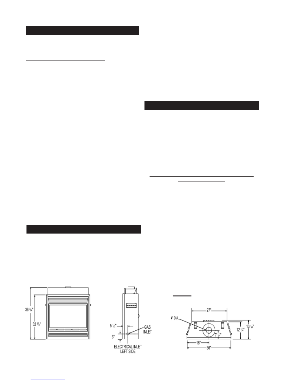
FIGURE 1
Page 5
VENTING
TH
TP
TH
O
T
P
I
L
L
O
I
H
N
F
L
O
T
O
P
I
F
O
THERMOSTAT OR
WALL SWITCH
VALV E
HIGH LIMIT
SWITCH
SAFETY
SWITCH
This is a vented appliance and must be connected to a
chimney in accordance with the current installation
codes. In absence of local codes, install to the current
National Fuel Gas Code, ANSI Z223.1, or the current
CAN/CGA B149, Installation Codes. This model can be
common-vented.
A minimum four inch diameter (4"ø) B-vent or class A vent
is required. A minimum 10' vent height is required. Secure
the B-vent to the exhaust collar on the stove top with 3
screws. In cold climates, the use of a B-vent and an insulated chase is recommended.
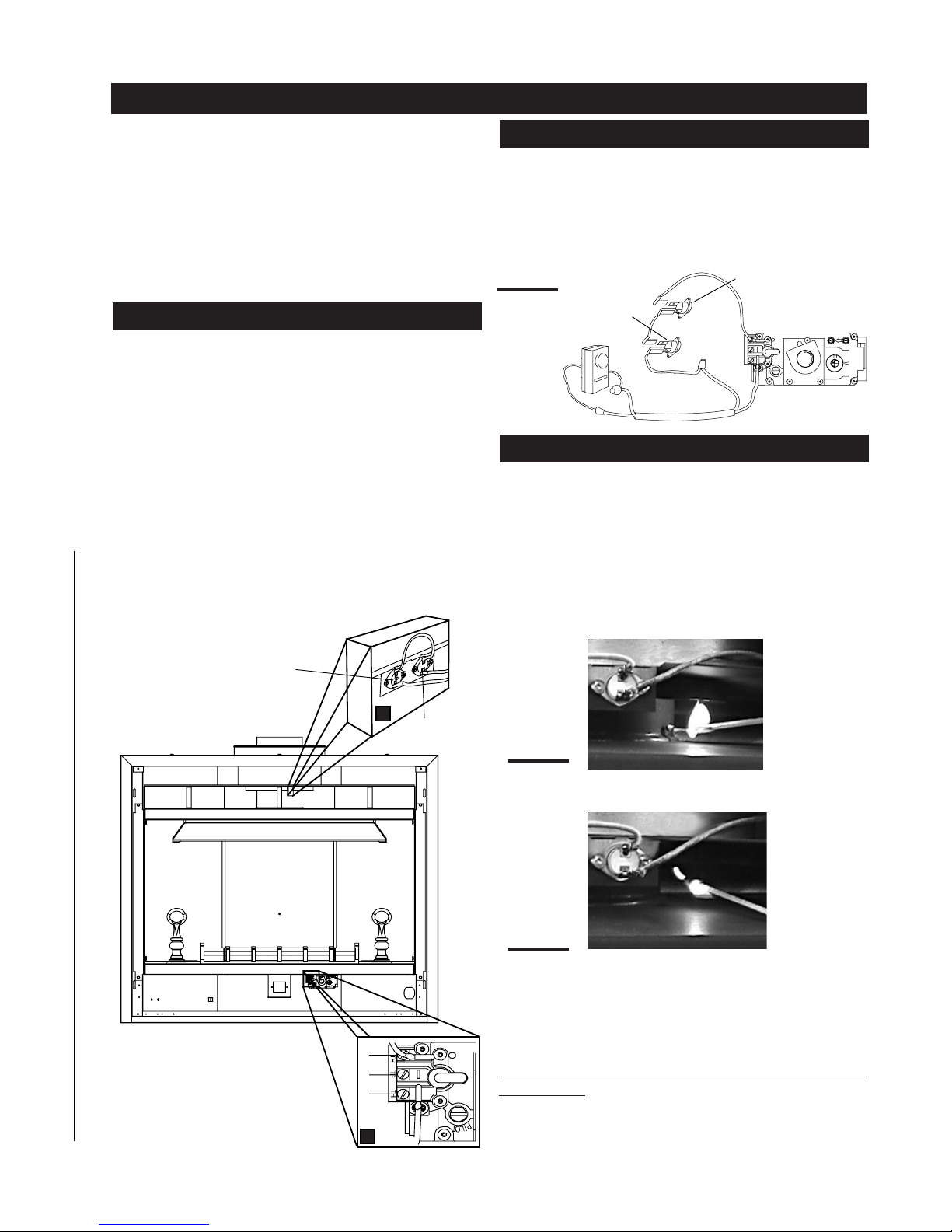
SAFETY SWITCH
This thermally activated switch, located in front of the draft
hood, senses an increase in temperature and acts as a
safety shut-off (See 'A' below). It shuts down the gas to the
main burner in the event of a severe downdraft of air or a
blocked or disconnected chimney flue. If the flue is blocked
or has no "draw", the safety switch will automatically shut
off the supply of gas to the main burner within 10 minutes.
This switch must be manually reset by depressing the
plunger. Refer to Figure 2.
Tampering with the safety switch can result in carbon
monoxide poisoning and possible death.
5
HIGH LIMIT SWITCH
This thermally activated switch, located in front of the draft
hood, senses an increase in temperature and acts as a
safety shut-off (See 'A' below). It shuts down the gas to the
main burner in the unlikely event of the unit overheating.
The HI Limit switch will automatically reset after the unit
has cooled down, resuming gas flow to the main burner.
FIGURE 3
VENTING ACTION CHECK
A test for correct venting action must be made before
the installed unit can be left with the customer.
Follow the procedure below:
1. Close all doors and windows in the room / start
exhaust fans in the home / turn the fireplace blower off (if so
equipped).
2. Set controls to "high" and light the unit.
3. Wait 5 minutes. Light a match and hold to the front of
the draft draft hood. FIGURES 4 & 5.
PLUNGER
A
HI LIMIT
SWITCH
FIGURE 4
Venting action is satisfactory, if smoke and flames are
drawn into the draft hood.
FIGURE 5
Venting action is unsatisfactory , if the smoke spills back, and
the flame splays outward. If venting action is unsatisfactory,
turn off the unit, wait 10 minutes and try again. If the smoke is
still not drawn into the draft hood, turn the unit off and check for
vent blockage or restriction. If necessary, consult with a quali-
1
2
3
fied inspector.
The Safety or Hi Limit switches must not be adjusted
or disabled.
In the event that either switch or any associated parts
B
are exchanged, only original manufacturer's parts
may be used.
W415-0275 /D / 10.01.07
Page 6
6
GAS INSTALLATION FRAMING
Proceed once the vent installation is complete.
1. Move the fireplace into position and secure using the
nailing tabs and/or secure to the floor through the 1/4"ø
holes located at either end of the base.
2. Route a 3/8" N.P.T. black iron gas line, 1/2" type-L
copper tubing or equivalent to the fireplace.
3. For ease of accessibility, an optional remote wall
switch or millivolt thermostat may be installed in a convenient location. Route 2-strand (solid core) millivolt wire
through the electrical hole located at the bottom left side of
the unit. The recommended maximum lead length depends on wire size:
WIRE SIZE MAX. LENGTH
14gauge 100 feet
16gauge 60 feet
Attach the one lead to terminal 3 (located on the gas valve)
and the other lead to the vent safety switch wire ( located
loose in the valve compartment). See FIGURE 3.
Do not connect either the wall switch, thermostat or
gas valve to electricity (110 volts).
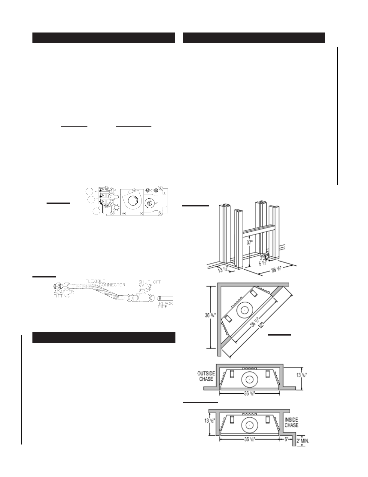
4. Install rigid black pipe, 1/2" type-L copper tubing or, if
local codes permit, a 3/8" flex connector and shutoff valve
to the gas line and the fireplace gas valve. Seal and tighten
securely. An adapter fitting is required between the gas
valve and the copper tubing or flex connector. DO NOT KINK
FLEXIBLE CONNECTOR. FIGURE 6.
5. Check for gas leaks by brushing on a soap and water
solution.
FIGURE 7
18gauge 40 feet
1
FIGURE 6
2
3
Do not use open flame.
L
O
F
I
H
P
I
L
O
T
O
F
N
O
P
L
T
I
O
It is best to frame your fireplace after it is positioned and
the vent system is installed. Use 2x4's and frame to local
building codes.
Combustible materials may be installed flush with the front
of the fireplace but must not cover any of the black faceareas of the fireplace. Non-combustible material (brick,
stone or ceramic tile) may protrude in these areas.
Combustible objects, like furniture, placed in front of the
fireplace, must be kept a minimum of 48" away from the
front face.
In order to avoid the possibility of exposed insulation and
vapour barrier coming into contact with the fireplace body , it
is recommended that the walls of the fireplace enclosure
be 'finished' (ie: drywall/sheetrock) as you would finish any
other wall of the home. This will ensure that clearance to
combustibles is maintained within the cavity.
It is not necessary to install a hearth extension with this
fireplace system.
When roughing in the fireplace, raise the fireplace to accommodate for the thickness of the finished floor materials, i.e. tile, carpeting, hard wood, which if not planned for
will interfere with the opening of the lower access door and
the installation of many decorative flashing accessories.
FIGURES 8
Purge all gas lines with the glass door of the fireplace
open. Assure that a continuous gas flow is at the burner
before closing the door.
CLEARANCE TO COMBUSTIBLE
MAINTAIN THESE MINIMUM CLEARANCES TO
COMBUSTIBLE CONSTRUCTION FROM FIREPLACE AND
VENT SURFACES:
Fireplace framing - 0” to stand-offs (rear, sides,bottom
and top).
Fireplace finishing.
Sides, back and bottom 0” inches
Enclosure top 12" inches
Recessed depth 13
Vent Pipe 1” inch, B-VENT
W415-0275 / D / 10.01.07
1
/4” inches
FIGURE 9
FIGURE 10a-b
Page 7

7
NAILING TAB INSTALLATION
1) Attach the nailing tabs to the corner posts using
the 2 sheet metal screws supplied. Secure through the centre of the top and
FIGURE 11
bottom slots in the nailing tab and then
through the existing holes in the corner posts.
If there are no existing holes, follow
these instructions:
Position the nailing tab so that the front
NAILING
TAB
face is offset with the front edge of the
corner post (approx. ½"). Centre the
nailing tab vertically on the corner
post.
Figure 12 a.
Drill through the centre of the top and
bottom slots in the nailing tab. Secure
using the two sheet metal screws
supplied. This allows the nailing tab
to slide back and forth for desired framing. Figure 12 b.
2) To determine the final location of the nailing tab
you must first determine the thickness of your finishing
material (i.e. drywall). This will determine the dimension
from the front edge of the corner post to the nailing tab.
Once the nailing tab is in the desired location, drill through
the centre hole of the nailing tab. Secure with a sheet metal
screw*. Figure 12 c.
* Additional set screws may be installed.
MINIMUM MANTLE AND
ENCLOSURE CLEARANCES
Combustible mantle clearance can vary according to the
mantle depth. Use the graph to help evaluate the clearance needed.
FIGURE 13 a
FIGURE 12 a-c
A
FINISHING
MATERIAL
CORNER
POST
NAILING
TAB
TOP SLOT
B
4” B-VENT
12”
4 5/8”
8” MANTLE
6”
4”
8”
2”
6”
FIRESTOP
1”
3”
TOP OF
FIREPLACE
4”
2”
FIGURE 13 b&c
12
M
A
10
N
T
L
8
E
6
H
E
4
I
G
H
2
T
1”
0
6
2 4
MANTLE DEPTH
128 10
C
CENTRE
HOLE
W415-0275 /D / 10.01.07
Page 8

8
FINISHING
DOOR OPENING & CLOSING
The upper louvres must be
removed to allow the door
to be opened or closed. To
access the lower door
latch, open the valve control door. Release the top
and bottom door latches, located at the right side of the
door.
FIGURE 13
FLANGE
UPPER LOUVRE
GVFL LOUVRE INSTALLATION
UPPER LOUVRES: Insert the
upper louvres into the slots
on both brackets. Press the
top flange of the hood into the
four clips located along the
top of the unit as shown.
LOWER LOUVRES: Attach
each hinge to the firebox with
2 screws. door and optional
louvre.
FIGURE 14
CLIP
DOOR LA TCH
HOOD
BRACKET
SLOT
LOUVRE
L36 LOUVRE INSTALLATION
FIGURE 17
A
B
C
FIGURE 15
LOWER LOUVRES
(V ALVE CONTROL DOOR)
HINGE SCREEN:Position the hinge screen into place and
with the control door open, secure to the firebox using three
screws.
FIGURE 16
A
B
C
CENTRE
SLOT
HINGE
CLIP
CLIPS
FLANGE
SLOT
TAB
SLOT
HOOD
Attach the hood by pressing the
top flange into the clips along
the top of the louvre opening.
Secure using a screw through
the centre slot.
UPPER LOUVRES
Insert the louvre tabs into the
slots located at the top left and
right corners of the unit.
LOWER LOUVRES
Insert the hinge clips into the
slots located at the bottom left
and right corners of the unit.
To remove the louvres, pull the
back tabs of the clips forward,
while pushing the louvre assembly back. Lift the clip.
W415-0275 / D / 10.01.07
Page 9

LOG PLACEMENT
PHAZER
Fireplaces, provide a unique and realistic glowing effect
that is different in every installation. Take the time to carefully position the glowing embers for a maximum glowing
effect.
Log colours
the colours will become more uniform as colour pigments
burn in during the heat activated curing process.
TM
logs and glowing embers exclusive to Napoleon
may vary . During the initial use of the fireplace,
FIGURE 18a-f
9
4. Position the notch located on the end of the center log
(#5) against the middle grate post with the other end of the
log resting in the pocket of the left crossover log.
SIDEVIEW
TAB
2. Move the two small logs (#2 & #3) into position, lining
up the studs located on the burner with the holes on the
bottom of the logs. Ensure that the small logs sit flat on the
burner.
1. Place the back log (#1) onto the log
support tray and in front of the tabs. The
tabs maintain an air space between the
log and firebox back to facilitate combustion air flow. Ensure that the back of the
log rests against the brackets on the back
wall of the firebox.
5. Place the bottom of the right crossover log (#6) against
the right firebox side and pulled forward to the grate. The
top of the log should rest in the pocket provided on the
center log (#5).
CHARCOAL EMBERS
Randomly place the charcoal embers along the front and
sides of the log support tray in a realistic manner. Fine dust
found in the bottom of the bag should not be used.
Tear the embers into pieces and place along the front row
GLOWING EMBERS
of ports covering all of the burner area in front of the small
logs (#2 & #3). Care should be taken to shred the embers
into thin, small irregular pieces as only the exposed edges
of the fibre hairs will glow. The ember material will only
glow when exposed to direct flame; however, care
should be taken to not block the burner ports.
Blocked burner ports can cause an incorrect flame pattern,
carbon deposits and delayed ignition. PHAZERTM logs glow
when exposed to direct flame. Use only certified "glowing
embers" and PHAZERTM logs available from your Napoleon dealer.
3. Place the bottom of the left crossover log (#4) against
the left firebox side and pulled forward to the grate.
The top of the log should rest in the pocket on the back log.
LOGO PLACEMENT
Remove the backing of the
logo supplied and place on the
glass viewing door, as indicated.
½"
LOGO
½"
FIGURE 19
W415-0275 /D / 10.01.07
Page 10

10
OPTIONAL BLOWER INSTALLATION
INSTALLATION TO BE
DONE BY A QUALIFIED
INSTALLER and must be
electrically connected and
grounded in accordance
with local codes. In the absence of local codes, use
the current CSA C22.1
CANADIAN ELECTRICAL CODE in
Canada or the
ANSI/NFPA 70
ELECTRICAL
FIGURE 21
Slide the vibration reducing pad (A) into the clip and onto
the threaded stud (B) at the other end, piercing a hole into
the pad. The blower must be able to be positioned entirely
onto the pad.
Tilt the blower onto its side. Slide it past the controls and
into the clip (C). Secure to the threaded stud using the lock
washer and wing nut provided. Ensure that the blower
does not touch the fireplace base or the firebox.
B
B
NATIONAL
CODE in the United States.
ADJUSTMENT
SLOTS
b
l
a
c
k
w
h
FIGURE 20
The three slots allow ease
of adjustment of the
blower. For a quiet running blower, do not allow
the assembly to sit on the
firebox base.
d
e
r
i
t
e
C
Attach the connectors from
the black and white wires
to the thermodisc and secure the thermodisc
bracket to the securing
stud at the bottom left of the
unit using a lock washer
and wing nut. Ensure that
the thermodisc touches
the firebox wall.
FIGURE 25
Attach the connectors from the black and
red wires to the blower.
Attach and secure the variable speed
switch using the nut provided. Plug the
harness cord into the receptacle.
THERMODISC
RECEPTACLE /
JUNCTION
GROUND
SCREW
FIGURE 24
BOX
The wire harness provided in this kit is a universal
harness. When installed, ensure that any excess
wire is contained, preventing it from making contact with moving or hot objects.
Because the blower is thermally activated, when
turned on, it will automatically start approximately
15 minutes after lighting the fireplace and will run
for approximately 30-45 minutes after the fireplace
has been turned off. Use of the fan increases the
output of heat.
Drywall dust will penetrate into the blower bearings causing irreparable damage. Care must be
taken to prevent drywall dust from coming into
contact with the blower or its compartment. Any
damage resulting from this condition is not covered by the warranty policy.
A
A
FIGURE 22 FIGURE23
W415-0275 / D / 10.01.07
Page 11

OPTIONAL FAN INSTALLATION
11
ELECTRICAL INST ALLATION TO BE DONE BY A QUALIFIED INSTALLER and must be connected and grounded
in accordance with local codes. In the absence of local
codes, use the current CSA C22.1 CANADIAN ELECTRICAL CODE
in Canada or the ANSI/NFPA 70 NATIONAL ELECTRICAL CODE in
the United States.
FIGURE 26
The wire harness provided in this kit is a universal harness. When installed, ensure that any excess wire is contained, preventing it from making contact with moving or
hot objects.
Position the vibration reducing pad into the clip and onto
the threaded stud at the other end, piercing a hole into the
pad. The fan assembly must be able to be positioned
entirely onto the pad.
FIGURE 27
BRACKET
OPEN ENDED
SLOTS
OPTIONAL THERMOSTATIC
JUNCTION BOX
SENSOR
RECEPTACLE /
VARIABLE SPEED/
PIEZO IGNITOR
Slide the fan assembly past the controls and and into the
clip. Secure using the lock washer and nut provided.
Plug the harness cord into the receptacle.
THERMOSTATIC SENSOR CONTROL
This optional kit is meant to be used only in conjunction
with the GD65 Fan Kit, shown above, which may be ordered from your Wolf Steel / Napoleon dealer.
With the thermostatic sensor option, the fan, when turned
on, becomes thermally activated, and will automatically run
approximately 10 minutes after the fireplace has been lit
and for approximately 30-45 minutes after the fireplace has
been turned off.
Use of the fan increases the output of heat.
Unplug the power cord from the receptacle. Connect all
wires as shown.
FIGURE 28
Attach and secure the sensor assembly bracket to the securing stud located next to the receptacle/junction box at
the bottom left of the unit using the lock washer and wing
nut. Ensure that the thermodisc touches the firebox wall.
Plug the power cord back into the receptacle.
When installed, ensure that any excess wire is contained,
preventing it from making contact with moving or hot objects.
THERMODISC
SENSOR ASSEMBLY
RECEPTACLE /
JUNCTION BOX
BRACKET
FIGURE 29
W415-0275 /D / 10.01.07
Page 12

12
N
L
O
F
F
O
KNOB
OPERATION / MAINTENANCE
Purge all gas lines with the glass door of the fireplace
opened. Assure that a continuous gas flow is at the
burner before closing the door.
When lit for the first time, the fireplace will emit a slight
odour for a few hours. This is a normal temporary condition caused by the curing of the logs and the "burn-in"
After extended periods of non-operation such as following a vacation or a warm weather season, the fireplace may emit a slight odour for a few hours. This is
caused by dust particles in the heat exchanger burning
off. In both cases, open a window to sufficiently ventilate the room.
of internal paints and lubricants used in the manufacturing process and will not occur again.
FOR YOUR SAFETY READ BEFORE LIGHTING: WHAT TO DO IF YOU SMELL GAS:
A. This fireplace is equipped with a pilot which must be lit
by hand while following these instructions exactly.
B. Before operating smell all around the fireplace area for
gas and next to the floor because some gas is heavier
than air and will settle on the floor.
C. Use only your hand to turn the gas control knob. Never
use tools. If the knob will not turn by hand, do not try to
repair it. Call a qualified service technician. Force or
attempted repair may result in a fire or explosion.
D. Do not use this fireplace if any part has been under
water. Immediately call a qualified service technician to
inspect the fireplace and replace any part of the control
system and any gas control which has been under water.
• Turn off all gas to the fireplace.
• Open windows.
FIGURE 30
• Do not try to light any appliance.
• Do not touch any electric switch; do
not use any phone in your building.
• Immediately call your gas supplier from a neighbour's
phone. Follow the gas supplier's instructions.
• If you cannot reach your gas supplier, call the fire department.
L
O
FLAME
FIGURE 31
P
I
L
O
T
ADJUSTMENT
KNOB
LIGHTING INSTRUCTIONS
WARNING: The gas valve has an interlock device which
will not allow the pilot burner to be lit until the thermocouple has cooled. Allow approximately 60 seconds for the
thermocouple to cool.
When lighting and re-lighting, the gas knob cannot be turned
from pilot to off unless the knob is depressed slightly.
1. Stop! Read the above safety information on this label.
2. Turn off all electric power to the fireplace.
3. Turn the gas knob clockwise to off.
4. Wait five (5) minutes to clear out any gas. If you smell
gas including near the floor. S top! Follow "B" in the above
safety information on this label. If you don't smell gas go
5. Turn gas knob counter-clockwise to pilot.
6. Depress slightly and hold gas knob while lighting the
pilot with the push button ignitor. Keep knob depressed
for one minute, then release. If pilot does not continue
to burn, repeat steps 3 through 5.
7. With pilot lit, depress and turn gas knob counter-clockwise
to on.
8. If equipped with remote on-off switch/thermostat, main
burner may not come on when you turn valve to on.
Remote switch must be in the on position to ignite
burner.
9. Turn on all electric power to the fireplace.
the next step.
TO TURN OFF GAS
I
T
P
O
GAS KNOB
F
O
I
F
H
N
O
P
T
L
I
O
PILOT
ON/OFF
1. Turn off all electric power to the fireplace if service is to
be performed.
W415-0275 / D / 10.01.07
2. Push in gas control knob slightly and turn clockwise
to off. Do not force.
Page 13

PILOT SCREW
MAINTENANCE
Turn off the gas and electrical power before servicing
the fireplace.
CAUTION: Label all wires prior to disconnection when servicing controls. Wiring errors can cause improper and dangerous operation. Verify proper operation after servicing.
This fireplace and its venting system should be inspected
before use and at least annually by a qualified service person. The fireplace area must be kept clear and free of combustible materials, gasoline or other flammable vapours
and liquids. The flow of combustion and ventilation air must
not be obstructed.
1. In order to properly clean the burner and pilot assembly,
remove the logs to expose both assemblies.
2. Keep the control compartment, logs, burner, air shutter
opening and the area surrounding the logs clean by vacuuming or brushing, at least once a year.
ADJUSTMENTS
13
3. Check to see that all burner ports are burning. Clean out
any of the ports which may not be burning or are not burning properly.
4. Check to see that the pilot flame is large enough to
engulf the thermocouple and thermopile and reaches toward the burner with the third jet.
5. Replace the cleaned logs.
6. Check to see that the main burner ignites completely on
all openings when the gas knob for the burner is turned
on. A 5 to 10 second total light-up period is satisfactory. If
ignition takes longer, consult your Napoleon dealer / distributor.
7. Check that the gasketing on the sides, top and bottom of
the door is not broken or missing. Replace if necessary.
PILOT BURNER ADJUSTMENT
Adjust the pilot screw to provide properly sized flame. Turn
in a clockwise direction to reduce the gas flow.
L
O
F
I
H
P
I
L
O
T
O
F
N
O
P
L
T
I
O
FIGURE 32
FIGURE 33
VENTURI ADJUSTMENT
MODEL BGNV36
NG
1/16"
AIR SHUTTER ADJUSTMENT MUST ONL Y BE DONE BY A
QUALIFIED GAS INSTALLER!
FIGURE 34
Air shutter is accessed beside gas valve.
VENTURI
LP
3/8"
Closing the air shutter will cause a more yellow flame, but
can lead to carboning. Opening the air shutter will cause a
more blue flame, but can cause flame lifting from the burner
ports. The flame may not appear yellow immediately; allow 15 to 30 minutes for the final flame colour to be established.
FIGURE 35 (not exactly as shown)
W415-0275 /D / 10.01.07
Page 14

14
REPLACEMENTS
Contact your dealer or the factory for questions concerning
prices and policies on replacement parts. Normally all parts
can be ordered through your Napoleon dealer or distributor.
When ordering replacement parts always give the following information:
1. MODEL & SERIAL NUMBER OF FIREPLACE
2. INSTALLATION DATE OF FIREPLACE
FOR WARRANTY REPLACEMENT PARTS, A PHOT OCOPY OF THE
ORIGINAL
INVOICE WILL BE REQUIRED TO HONOUR THE CLAIM.
3. PART NUMBER
4. DESCRIPTION OF PART
5. FINISH
* IDENTIFIES ITEMS WHICH ARE NOT ILLUSTRATED. FOR FURTHER INFORMATION, CONTACT YOUR NAPOLEON DEALER.
REPLACEMENT PARTS ACCESSORIES
# PART NO. DESCRIPTION
1 W357-0001 PIEZO IGNITER
2 W680-0004 THERMOPILE
3 W680-0005 THERMOCOUPLE
4 W010-0764 BURNER
5 W010-0800 NATURAL GAS PILOT ASSEMBL Y
5 W010-0801 PROPANE GAS PILOT ASSEMBLY
6 W660-0021 SAFETY SWITCH
7 W660-0007 HI LIMIT SWITCH
8* W660-0005 ON/OFF TOGGLE SWITCH
9 W455-0069 NATURAL GAS PILOT INJECTOR
9 W455-0067 PROPANE GAS PILOT INJECTOR
10 W725-0025 NATURAL GAS VAL VE
10 W725-0026 PROPANE GAS VALVE
11* W385-0245 NAPOLEON LOGO
12* GD660 STANDARD WALL SWITCH & 20FT OF WIRE
13* W225-0099 BLACK DOOR FRAME
14 W010-0856 GLASS c/w GASKET
15 W010-0857 BLACK DOOR C/W GLASS
16 W455-0093 #48 NATURAL GAS ORIFICE
16 W455-0047 #56 PROPANE GAS ORIFICE
17 GL-639 LOG SET
18 W361-0016 GLOWING EMBERS
19 W550-0001 CHARCOAL EMBERS
20 W135-0183 BACK LOG (#1)
21 W135-0184 LEFT MIDDLE LOG (#2)
22 W135-0185 RIGHT MIDDLE LOG (#3)
23 W135-0186 LEFT CROSSOVER LOG (#4)
24 W135-0187 MIDDLE CROSSOVER LOG (#5)
25 W135-0188 RIGHT CROSSOVER LOG (#6)
26 W010-0805 LOUVRE HOOD
W/ LOUVRE BRACKETS
# PART NO. DESCRIPTION
27* W690-0001 MILLIVOLT THERMOST A T
28* W660-0010 REMOTE CONTROL 28* W660-0011 REMOTE CONTROL - ADVANTAGE PLUS
29 GZ550-1KT BLOWER KIT
30* GD65 FAN KIT
31* GD36 THERMOSTATIC SENSOR CONTROL KIT USE WITH GD65 ONLY
32* W500-0033 VARIABLE SPEED SWITCH WALL MOUNTING PLATE
33 GA-566 HOT AIR DISTRIBUTION KIT
34* W690-0005 THERMOSTAT 110V FOR USE WITH GA-566
35 GA-72 HOT AIR EXHAUST KIT
36 GA-70 EXTENSION KIT 5FT
37 GVFLK-1 LOUVRE KIT, UPPER & LOWER - BLACK
37 GVFLPB-1 LOUVRE KIT, UPPER & LOWER - POLISHED BRASS
37 GVFLAB-1 LOUVRE KIT, UPPER & LOWER - ANTIQUE BRASS
37 GVFLSS-1 LOUVRE KIT, UPPER & LOWER - BRUSHED STAINLESS STEEL
38 L36K LOUVRE KIT - UPPER & LOWER - BLACK
39 HOIG-1 HERITAGE ORNAMENTAL INSETS - GOLD P LATED
39 HOIKG-1 HERITAGE ORNAMENTAL INSETS - BLACK GOLD PLATED
39 HOIBC-1 HERITAGE ORNAMENTAL INSETS - BRUSHED COPPER PLATED
39 HOIBG-1 HERITAGE ORNAMENTAL INSETS - BRUSHED GOLD PLATED
40 DOIG-1 DIAMOND ORNAMENTAL INSETS - GOLD PLATED
40 DOIKG-1 DIAMOND ORNAMENTAL INSETS- BLACK GOLD PLATED
40 DOIBC-1 DIAMOND ORNAMENTAL INSETS- BRUSHED COPPER PLATED
40 DOIBG-1 DIAMOND ORNAMENTAL INSETS- BRUSHED GOLD PLATED
41 GOIG-1 GOTHIC ORNAMENTAL INSETS - GOLD PLATED
41 GOIKG-1 GOTHIC OR NAMENTAL INSETS - BLACK GOLD PLATED
41 GOIBC-1 GOTHIC ORNAMENTAL INSETS - BRUSHED COPPER PLATED
41 GOIBG-1 GOTHIC ORNAMENTAL INSETS - BRUSHED GOLD PLATED
42 SOIG-1 SEASHELL ORNAMENTAL INSETS - GOLD PLATED
42 SOIKG-1 SEASHELL ORNAMENTAL INSETS - BLACK GOLD PLATED
42 SOIBC-1 SEASHELL ORNAMENTAL INSETS - BRUSHED COPPER PLATED
42 SOIBG-1 SEASHELL ORNAMENTAL INSETS - BRUSHED GOLD PLATED
43 EOIG-1 ECLIPSE ORNAMENTAL INSETS - GOLD PLATED
43 EOIKG-1 ECLIPSE ORNAMENTAL INSETS - BLACK GOLD PLATED
43 EOIBC-1 ECLIPSE ORNAMENTAL INSETS - BRUSHED COPPER PLATED
43 EOIBG-1 ECLIPSE ORNAMENTAL INSETS - BRUSHED GOLD PLATED
44 DK36-R DOOR KIT, RECTANGULAR - BLACK
44 DK36-RG DOOR KIT, RECTANGULAR - GOLD PLATED
45 DK36-A DOOR KIT, ARCHED - BLACK
45 DK36-AG DOOR KIT, ARCHED - GOLD PLATED
46 DK36-W DOOR KIT, WEBBED - BLACK
46 DK36-WG DOOR KIT, WEBBED - GOLD PLATED
47* W175-0159 FUEL CONVERSION KIT - NG-LP
47* W175-0164 FUEL CONVERSION KIT - LP-NG
ADVANTAGE
W415-0275 / D / 10.01.07
Page 15

15
W415-0275 /D / 10.01.07
Page 16

16
TROUBLE SHOOTING GUIDE
B
EFORE ATTEMPTING TO TROUBLESHOOT, PURGE YOUR UNIT AND INITIALLY LIGHT THE PILOT AND THE MAIN BURNER WITH THE GLASS DOOR OPENED
SYMPTOM PROBLEM TEST SOLUTION
.
Main burner goes
out; pilot stays on.
Main burner goes
out; pilot goes out.
Pilot goes out when
the gas knob is released.
The gas valve has
an interlock device
which will not allow
the pilot burner to
be lit until the thermocouple has
cooled. Allow approximately 60
seconds for the
thermocouple to
cool.
Pilot burning; no
gas to main
burner; gas knob
is on 'HI'; wall
switch / thermostat
is on.
Pilot will not light. - check if pilot can be lit by a match
W415-0275 / D / 10.01.07
Pilot flame is not large
enough or not engulfing the
thermopile
Thermopile shorting - clean thermopile connection to the valve. Reconnect.
Remote wall switch wire is
too long; too much resistance in the system.
Faulty thermostat or switch. - replace.
Vent safety switch has
opened. (Tripped)
Hi Limit switch has opened.
(Tripped)
Refer to "MAIN BURNER GOES OUT ; PILOT STAYS ON"
Faulty thermocouple. - replace.
System is not correctly
purged.
Out of propane gas. - fill the tank.
Pilot flame is not large
enough
Pilot flame is not engulfing
the thermocouple.
Thermocouple shorting /
faulty.
Faulty valve.
Themostat or switch is de-
fective.
Wall switch wiring is defective.
Main burner orifice is plugged. - remove stoppage in orifice.
Faulty valve.
Vent safety switch has opened.
(Tripped)
Hi Limit switch has opened. (Tripped)
No spark at pilot burner
Spark gap is incorrect - spark gap should be 0.150" to 0.175" (5/32" to 11/64" approx.) from
No gas at the pilot burner
- turn up pilot flame.
- replace pilot assembly.
- replace thermopile / valve.
- shorten wire to correct length or wire gauge.
- Vent has become blocked or disconnected. Correct. See Figure 2.
- Unit has overheated. See Figure 2
- purge the gas line with the glass door open.
- turn up the pilot flame.
- gently twist the pilot head to improve the flame pattern around the
thermocouple.
- loosen and tighten thermocouple.
- clean thermocouple and valve connection.
- replace thermocouple.
- replace.
- connect a jumper wire across the wall switch terminals; if main
burner lights, replace switch / thermostat.
- disconnect switch wires & connect a jumper wire across terminals
1 & 3; if the main burner lights, check the wires for defects and / or
replace wires.
- replace.
- Vent has become blocked or disconnected. Correct. See Figure 2.
- Unit has overheated. See Figure 2
- check that the wire is connected to the push button ignitor.
- check if the push button ignitor needs tightening.
- replace the wire if the wire insulation is broken or frayed.
- replace the electrode if the ceramic insulator is cracked or broken.
- replace the push button ignitor.
- fill the tank.Out of propane gas
the electrode tip and the pilot burner. To ensure proper electrode
location, tighten securing nut (finger tight plus 1/4 turn).
- check that the manual valve is turned on.
- check the pilot orifice for blockage.
- replace the valve.
- call the gas distributor.
Page 17

SYMPTOM PROBLEM TEST SOLUTION
17
Pilot goes out
while standing;
Main burner is in
'OFF' position.
Flames are consistently too large
or too small.
Carboning occurs.
P
I
L
O
T
Carbon is being
deposited on
glass, logs or combustion chamber
surfaces.
Gas piping is undersized. - turn on all gas appliances and see if pilot flame flutters, dimin-
ishes or extinguishes, especially when main burner ignites. Monitor
appliance supply working pressure.
- check if supply piping size is to code. Correct all undersized piping.
Unit is over-fired or underfired.
- check pressure readings:
Inlet pressure can be checked by turning screw (A) counter-clockwise 2 or 3 turns and then placing pressure gauge tubing over the
A
B
test point. Gauge should read 7" (minimum 4.5") water column for
natural gas or 13" (11" minimum) water column for propane. Check
that main burner is operating on "HI".
L
O
F
I
H
O
F
N
O
P
L
T
I
O
Outlet pressure can be checked the same as above using screw
(B). Gauge should read 3.5" water column for natural gas or 10"
water column for propane. Check that main burner is operating on
"HI".
AFTER TAKING PRESSURE READINGS, BE SURE TO TURN
SCREWS CLOCKWISE FIRMLY TO RESEAL. DO NOT OVERTORQUE.
Leak test with a soap and water solution.
Air shutter has become
- ensure air shutter opening is free of lint or other obstructions.
blocked
Flame is impinging on the
logs or combustion chamber.
- check that the logs are correctly positioned.
- open air shutter to increase the primary air.
- check the input rate: check the manifold pressure and orifice size
as specified by the rating plate values.
- check to ensure proper venting action
White / grey film
forms.
Exhaust fumes
smelled in room,
headaches.
Main burner flame
is a blue, lazy,
transparent flame.
Remote wall
switch is in "OFF"
position; main
burner comes on
when gas knob is
turned to "ON" position.
Sulphur from fuel is being
deposited on glass, logs or
combustion chamber surfaces.
- clean the glass with a recommended gas fireplace glass cleaner.
DO NOT CLEAN GLASS WHEN HOT.
If deposits are not cleaned off regularly, the glass may become
permanently marked.
Fireplace is spilling. - check for chimney blockage
- check that chimney is installed to building code.
- room is in negative pressure; increase fresh air supply.
Not enough combustion air - room is in negative pressure; increase fresh air supply
Wall switch is mounted up-
- reverse.
side down
- replace.Remote wall switch is
grounding.
- check for ground (short); repair ground or replace wire.Remote wall switch wire is
grounding.
Faulty valve.
- replace.
W415-0275 /D / 10.01.07
Page 18

18
Service Performed Special ConcernsDealer Name
Name
Service T echnician
Wolf Steel Fireplace Service History
This fireplace must be serviced annually depending on usage.
Date
W415-0275 / D / 10.01.07
Page 19

NOTES
19
W415-0275 /D / 10.01.07
Page 20

20
NOTES
W415-0275 / D / 10.01.07
 Loading...