

Page 1
INSTALLER: LEAVE THIS MANUAL WITH THE APPLIANCE.
CONSUMER: RETAIN THIS MANUAL FOR FUTURE REFERENCE.
NEVER LEAVE CHILDREN OR OTHER AT RISK INDIVIDUALS ALONE WITH THE APPLIANCE
INSTALLATION AND
OPERATING INSTRUCTIONS
CERTIFIED UNDER CANADIAN AND AMERICAN NATIONAL STANDARDS: CSA 2.22, ANSI Z21.50 FOR VENTED GAS FIREPLACES.
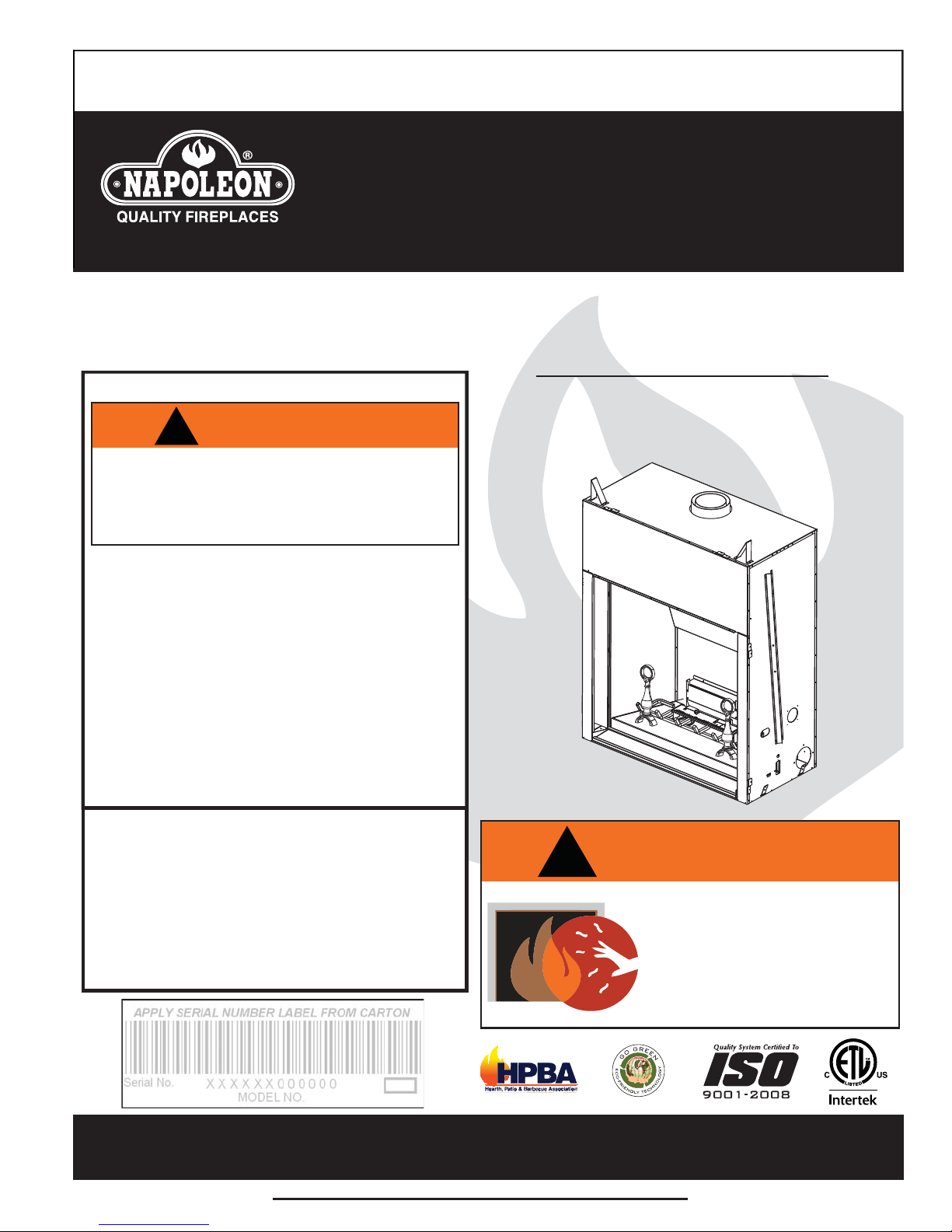
BGD90NT-E
CERTIFIED FOR CANADA AND UNITED STATES USING ANSI/CSA METHODS.
SAFETY INFORMATION
NATURAL GAS
CERTIFIED FOR CANADA AND UNITED STATES USING ANSI/CSA METHODS.
If the information in these instructions
are not followed exactly, a fi re or
explosion may result causing property
damage, personal injury or loss of life.
- Do not store or use gasoline or other fl ammable
vapors and liquids in the vicinity of this or any
other appliance.
- WHAT TO DO IF YOU SMELL GAS:
• Do not try to light any appliance.
• Do not touch any electrical switch; do not use
any phone in your building.
• Immediately call your gas supplier from a
neighbour’s phone. Follow the gas supplier’s
instructions.
• If you cannot reach your gas supplier, call the
fi re department.
- Installation and service must be performed by a
qualifi ed installer, service agency or the supplier.
This appliance may be installed in an aftermarket,
permanently located, manufactured home (USA
only) or mobile home, where not prohibited by
local codes.
This appliance is only for use with the type of gas
indicated on the rating plate. This appliance is
not convertible for use with other gases, unless a
certifi ed kit is used.
!
WARNING
BGD90PT-E
PROPANE
!
WARNING
HOT GLASS WILL CAUSE
BURNS.
DO NOT TOUCH GLASS UNTIL
COOLED.
NEVER ALLOW CHILDREN TO
TOUCH GLASS.
Wolf Steel Ltd., 24 Napoleon Rd., Barrie, ON, L4M 0G8 Canada /
103 Miller Drive, Crittenden, Kentucky, USA, 41030
Phone (705)721-1212 • Fax (705)722-6031 • www.napoleonfi replaces.com • ask@napoleonproducts.com
$10.00
1.28C
W415-1107 / 04.27.12
Page 2

2
TABLE OF CONTENTS
1.0 INSTALLATION OVERVIEW 3
2.0 INTRODUCTION 4
3.0 VENTING 8
4.0 INSTALLATION 16
5.0 FRAMING 22
6.0 ELECTRICAL CONNECTION 28
7.0 FINISHING 30
8.0 REMOTE AND VALVE ACCESS 36
9.0 OPERATION 38
10.0 OPERATING INSTRUCTIONS 43
11.0 ADJUSTMENTS 44
12.0 MAINTENANCE 46
13.0 REPLACEMENTS 48
14.0 TROUBLESHOOTING 52
15.0 WARRANTY 55
2.1 DIMENSIONS 5
2.2 GENERAL INSTRUCTIONS 5
2.3 GENERAL INFORMATION 6
2.4 RATING PLATE INFORMATION 7
3.1 VENTING LENGTHS AND COMPONENTS 8
3.2 TYPICAL VENT INSTALLATION 9
3.3 VENT TERMINAL CLEARANCES 10
3.4 VENTING APPLICATION FLOW CHART 11
3.5 DEFINITIONS 11
3.6 ELBOW VENT LENGTH VALUES 11
3.7 TOP EXIT HORIZONTAL TERMINATION 12
3.8 TOP EXIT VERTICAL TERMINATION 14
4.1 WALL AND CEILING PROTECTION 16
4.1.1 HORIZONTAL INSTALLATION 17
4.1.2 VERTICAL INSTALLATION 17
4.2 USING FLEXIBLE VENT COMPONENTS 18
4.2.1 HORIZONTAL AIR TERMINAL INSTALLATION 18
4.2.2 VERTICAL AIR TERMINAL INSTALLATION 19
4.2.3 APPLIANCE VENT CONNECTION 20
4.3 MOBILE HOME INSTALLATION 20
4.4 GAS INSTALLATION 21
5.1 MINIMUM CLEARANCE TO COMBUSTIBLES 24
5.2 MINIMUM ENCLOSURE CLEARANCES 26
5.3 MINIMUM MANTEL CLEARANCES 27
6.1 RECEPTACLE WIRING DIAGRAM 29
6.2 OPTIONAL BLOWER INSTALLATION 29
7.1 DOOR REMOVAL 30
7.2 LOG SHIPPING BRACKET 32
7.3 BRICK PANEL INSTALLATION 32
7.4 ANDIRON PLACEMENT 33
7.5 LOG PLACEMENT 34
7.6 CHARCOAL EMBERS 35
7.7 VERMICULITE 35
7.8 GLOWING EMBERS 35
8.1 INNER ACCESS PANEL 36
8.2 BULKHEAD ACCESS PLATE 36
8.3 REMOTE RECEIVER REMOVAL 36
8.4 CONTROL MODULE REMOVAL 37
8.5 VALVE REMOVAL 37
9.1 GENERAL TRANSMITTER LAYOUT 38
9.2 APPLIANCE OPERATION 38
9.3 HAND HELD REMOTE OPERATIONS 39
9.4 TEMPERATURE DISPLAY 39
9.5 ROOM THERMOSTAT 39
9.6 SMART THERMOSTAT 40
9.7 FLAME HEIGHT 40
9.8 FAN SPEED 40
9.9 CHILD PROOF FUNCTION 41
9.10 NIGHT LIGHTS 41
9.11 LOW BATTERY / MANUAL BYPASS 41
9.12 IN THE EVENT OF A POWER FAILURE 42
9.13 CONTROL MODULE 42
9.14 TIMED BLOWER 42
11.1 PILOT BURNER ADJUSTMENT 44
11.2 VENTURI ADJUSTMENT 44
11.3 FLAME CHARACTERISTICS 45
11.4 RESTRICTING VERTICAL VENTS 45
12.1 CARE OF GLASS 46
12.2 GLASS / DOOR REPLACEMENT 47
12.3 NIGHT LIGHT
TM
REPLACEMENT 47
NOTE: Changes, other than editorial, are denoted by a vertical line in the margin.
W415-1107 / 07.24.12
Page 3
1.0 INSTALLATION OVERVIEW
See the section “FRAMING”
for Non-combustible material
See the section
“MINIMUM MANTEL
CLEARANCES”
See the section
“FRAMING” and
“MINIMUM
ENCLOSURE
CLEARANCES”
for Drywall (or
other combustible material)
3
See the section
“VENTING” and
“INSTALLATION”
See the section
“FRAMING”
See the section
“FRAMING”
Side
Wall
Rating plate, see
“RATING PLATE
INFORMATION”
section.
W415-1107 / 07.24.12
Page 4

4
2.0 INTRODUCTION
• THIS APPLIANCE IS HOT WHEN OPERATED AND CAN CAUSE SEVERE BURNS IF CONTACTED.
• ANY CHANGES TO THIS APPLIANCE OR IT’S CONTROLS CAN BE DANGEROUS AND IS PROHIBITED.
• Do not operate appliance before reading and understanding operating instructions. Failure to operate appliance
according to operating instructions could cause fi re or injury.
• Risk of fi re or asphyxiation do not operate appliance with fi xed glass removed.
• Do not connect 110 volts to the control valve.
• Risk of burns. The appliance should be turned off and cooled before servicing.
• Do not install damaged, incomplete or substitute components.
• Risk of cuts and abrasions. Wear protective gloves and safety glasses during installation. Sheet metal edges may be
sharp.
• Do not burn wood or other materials in this appliance.
• Children and adults should be alerted to the hazards of high surface temperature and should stay away to avoid burns or
clothing ignition.
• Young children should be carefully supervised when they are in the same room as the appliance.
young children and others may be susceptible to accidental contact burns. A physical barrier is recommended if there
are at risk individuals in the house. To restrict access to an appliance or stove, install an adjustable safety gate to keep
toddlers, young children and other at risk individuals out of the room and away from hot surfaces.
• Clothing or other fl ammable material should not be placed on or near the appliance.
• Due to high temperatures, the appliance should be located out of traffi c and away from furniture and draperies.
• Ensure you have incorporated adequate safety measure to protect infants/toddlers from touching hot surfaces.
• Even after the appliance is out, the glass and/or screen will remain hot for an extended period of time.
• Check with your local hearth specialty dealer for safety screens and hearth guards to protect children from hot surfaces.
These screens and guards must be fastened to the fl oor.
• Any safety screen or guard removed for servicing must be replaced prior to operating the appliance.
• The appliance is a vented gas-fi red appliance. Do not burn wood or other materials in the appliance.
• It is imperative that the control compartments, burners and circulating blower and its passageway in the appliance
and venting system are kept clean. The appliance and its venting system should be inspected before use and at least
annually by a qualifi ed service person. More frequent cleaning may be required due to excessive lint from carpeting,
bedding material, etc. The appliance area must be kept clear and free from combustible materials, gasoline and other
fl ammable vapors and liquids.
• Under no circumstances should this appliance be modifi ed.
• This appliance must not be connected to a chimney fl ue pipe serving a separate solid fuel burning appliance.
• Do not use this appliance if any part has been under water. Immediately call a qualifi ed service technician to inspect the
appliance and to replace any part of the control system and any gas control which has been under water.
• Do not operate the appliance with the glass door removed, cracked or broken. Replacement of the glass should be done
by a licensed or qualifi ed service person.
• Do not strike or slam shut the appliance glass door.
• When equipped with pressure relief doors, they must be kept closed while the appliance is operating to prevent exhaust
fumes containing carbon monoxide, from entering into the home. Temperatures of the exhaust escaping through these
openings can also cause the surrounding combustible materials to overheat and catch fi re.Only doors / optional fronts
certifi ed with the unit are to be installed on the appliance.
• Only doors / optional fronts certifi ed with the unit are to be installed on the appliance.
• Keep the packaging material out of reach of children and dispose of the material in a safe manner. As with all plastic
bags, these are not toys and should be kept away from children and infants.
• As with any combustion appliance, we recommend having your appliance regularly inspected and serviced as well as
having a Carbon Monoxide Detector installed in the same area to defend you and your family against Carbon Monoxide.
• Ensure clearances to combustibles are maintained when building a mantel or shelves above the appliance. Elevated
temperatures on the wall or in the air above the appliance can cause melting, discolouration or damage to decorations, a
T.V. or other electronic components.
• This appliance uses and requires a fast acting thermocouple. Replace only with a fast acting thermocouple supplied by
Wolf Steel Ltd.
!
WARNING
Toddlers,
3.1C
W415-1107 / 07.24.12
Page 5
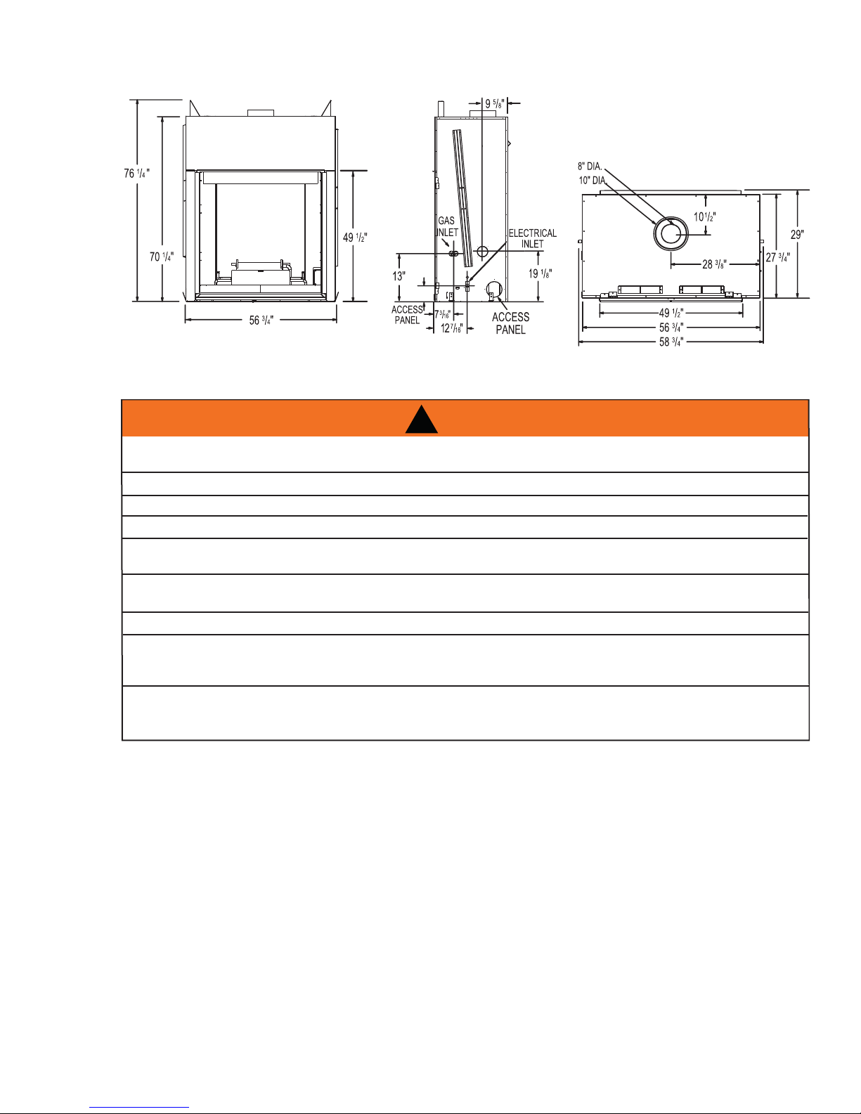
2.1 DIMENSIONS
2.2 GENERAL INSTRUCTIONS
ALWAYS LIGHT THE PILOT WHETHER FOR THE FIRST TIME OR IF THE GAS SUPPLY HAS RUN OUT,
WITH THE GLASS DOOR OPENED OR REMOVED.
PROVIDE ADEQUATE CLEARANCE FOR SERVICING AND OPERATING THE APPLIANCE.
NEVER OBSTRUCT THE FRONT OPENING OF THE APPLIANCE.
OBJECTS PLACED IN FRONT OF THE APPLIANCE MUST BE KEPT A MINIMUM OF 48” FROM THE
SURFACES AROUND AND ESPECIALLY ABOVE THE APPLIANCE CAN BECOME HOT. AVOID CONTACT
WHEN THE APPLIANCE IS OPERATING.
HIGH PRESSURE WILL DAMAGE VALVE. DISCONNECT GAS SUPPLY PIPING BEFORE PRESSURE TESTING GAS
LINE AT TEST PRESSURES ABOVE 1/2 PSIG. CLOSE THE MANUAL SHUT-OFF VALVE BEFORE PRESSURE
TESTING GAS LINE AT TEST PRESSURES EQUAL TO OR LESS THAN 1/2 PSIG.
USE ONLY WOLF STEEL APPROVED OPTIONAL ACCESSORIES AND REPLACEMENT PARTS WITH THIS APPLIANCE.
USING NON-LISTED ACCESSORIES (BLOWERS, DOORS, LOUVRES, TRIMS, GAS COMPONENTS, VENTING
COMPONENTS, ETC.) COULD RESULT IN A SAFETY HAZARD AND WILL VOID THE WARRANTY AND CERTIFICATION.
6"
!
WARNING
PROVIDE ADEQUA TE VENTILA TION.
FRONT FACE OF THE APPLIANCE.
FIRE RISK. EXPLOSION HAZARD.
5
THIS GAS APPLIANCE SHOULD BE INSTALLED AND SERVICED BY A QUALIFIED INSTALLER to
conform with local codes. Installation practices vary from region to region and it is important to know the
specifi cs that apply to your area, for example in Massachusetts State:
• This product must be installed by a licensed plumber or gas fi tter when installed within the commonwealth
of Massachusetts.
• The appliance damper must be removed or welded in the open position prior to installation of an appliance
insert or gas log.
• The appliance off valve must be a “T” handle gas cock.
• The fl exible connector must not be longer than 36 inches.
• A Carbon Monoxide detector is required in all rooms containing gas fi red appliances.
• The appliance is not approved for installation in a bedroom or bathroom unless the unit is a direct vent
sealed combustion product.
W415-1107 / 07.24.12
Page 6
6
A
A
The installation must conform with local codes or, in
absence of local codes, the National Gas and Propane
Installation Code CSA B149.1 in Canada, or the National
Fuel Gas Code, ANSI Z223.1 / NFPA 54 in the United
States. Suitable for mobile home installation if installed in
accordance with the current standard CAN/CSA Z240MH
Series, for gas equipped mobile homes, in Canada or
NSI Z223.1 and NFPA 54 in the United States.
s long as the required clearance to combustibles is
maintained, the most desirable and benefi cial location
for an appliance is in the center of a building, thereby
allowing the most effi cient use of the heat created. The location of windows, doors and the traffi c fl ow in the
room where the appliance is to be located should be considered. If possible, you should choose a location
where the vent will pass through the house without cutting a fl oor or roof joist.
If the appliance is installed directly on carpeting, vinyl tile or other combustible material other than wood
fl ooring, the appliance shall be installed on a metal or wood panel extending the full width and depth.
Some appliances have optional fans or blowers. If an optional fan or blower is installed, the junction box must
be electrically connected and grounded in accordance with local codes, use the current CSA C22.1 Canadian
Electrical Code in Canada or the ANSI/NFPA 70 National Electrical code in the United States.
www.ncertied.org
We suggest that our gas
hearth products be installed
and serviced by professionals
who are certied in the U.S.
by the National Fireplace
®
Institute
(NFI) as NFI Gas
Specialists
4.1A
NOTE: Non-combustible fi nishing material (i.e. Cement board, brick, stone, tile) must be used to fi nish
the front of the appliance.
2.3 GENERAL INFORMATION
FOR YOUR SATISFACTION, THIS APPLIANCE HAS BEEN TEST-FIRED TO ASSURE ITS OPERATION AND
QUALITY!
NG LP
Altitude (FT) 0-4,500 0-4,500
Max. Input (BTU/HR) 50,000 50,000
Max. Output Steady State (BTU/HR) 33,540 34,000
Effi ciency (w/the fan on) 63% 61%
Min. Inlet Gas Supply Pressure 4.5" Water Column 11" Water Column
Max. Inlet Gas Supply Pressure 7" Water Column 13" Water Column
Manifold Pressure (Under Flow Conditions) 3.5" Water Column 10" Water Column
This appliance is approved for bathroom, bedroom and bed-sitting room installations and is certifi ed for mobile
home installation. The natural gas model can only be installed in a mobile home that is permanently positioned
on its site and fueled with natural gas.
This appliance is only for use with the type of gas indicated on the rating plate. This appliance is not convertible for use with other gases, unless kit is used. Not external electricity (110 volts or 24 volts) is required for the
gas system operation.
Expansion / contraction noised during heating up and cooling down cycles are normal and are to be expected.
Change in fl ame appearance from “HI” to “LO” is more evident in natural gas than in propane.
W415-1107 / 07.24.12
Page 7
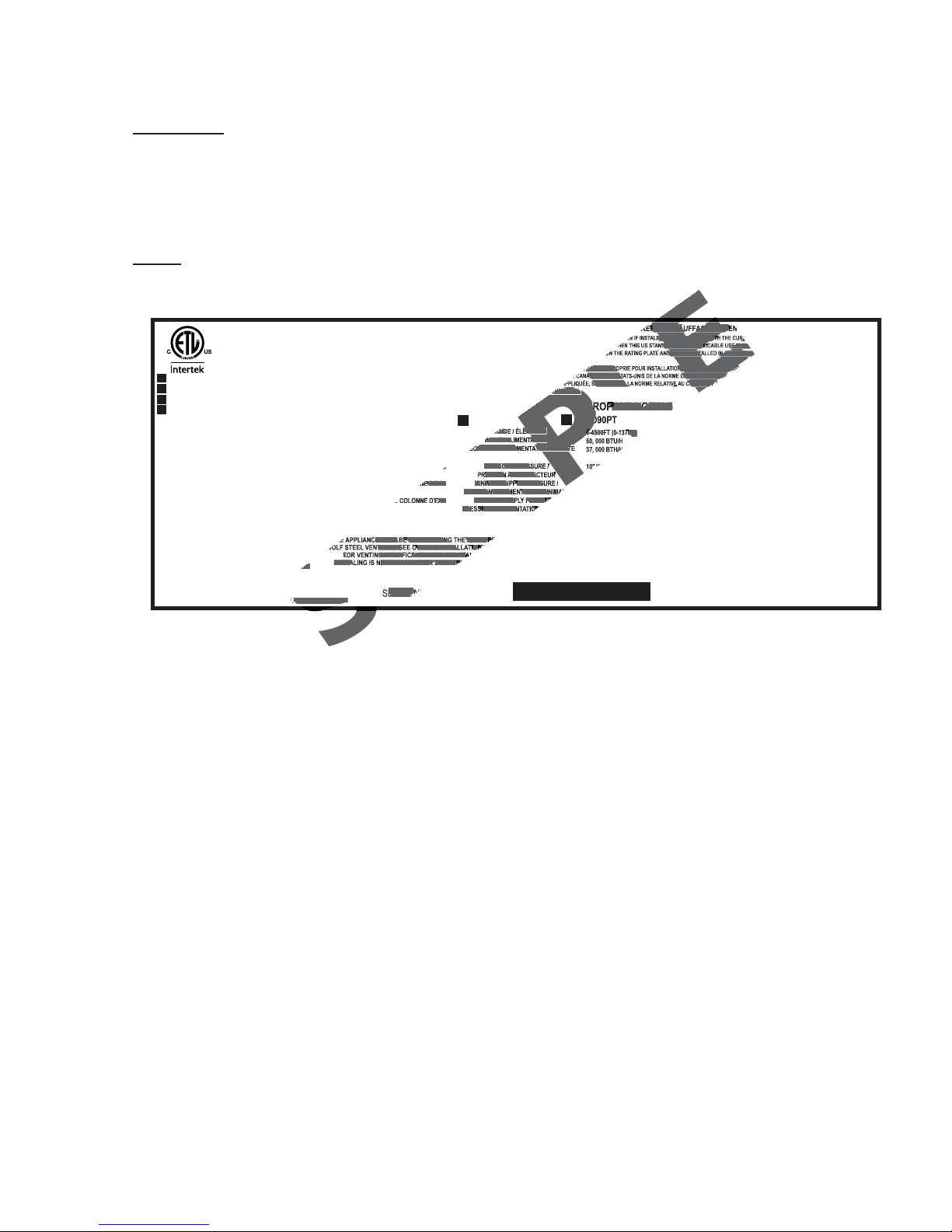
2.4 RATING PLATE INFORMATION
EIL DE CHAUFFAGE ALIME
LLED IN ACCORDANCE WITH THE CURR
NDARD IS NOT APPLICABLE USE THE ST
ON THE RATING PLATE AND MAY BE INSTALLED IN AN AFTER MA
TUDIO. APPROPRIÉ POUR INSTALLATION DANS UNE MAISON MOB
ADA OU AUX ÉTATS-UNIS DE LA NORME DE SECURITÉ ET DE
SE RÉFÉRER A LA NORME RELATIVE AU CRITÈRE DE M
SI/NFPA 501A.
UM
ITUDE / ÉLÉVATION
INPUT / ALIMENTA TION
CED INPUT / ALIMENTA TION RÉDUITE
E D'EAU
EAU
0-4500FT (0-1370M)
E MUST BE VENTED USING THE APPROP
T KITS. SEE OWNERS INSTALLATION
FOR VENTING SPECIFICS. PROPER REINSTA
RESEALING IS NECESSARY AFTER SERVICIN
ERIAL N
MANIFOLD PRESSURE /
RESSION AU COLLECTEUR
MINIMUM SUPPLY PRESS
PRESSION D'ALIMENTATION MIN
MAXIMUM SUPPLY PRESSUR
PRESSION D'ALIMENTATION
INSTALLER: It is your responsibility to check off the appropriate box on the rating plate according to
the model, venting and gas type of the appliance.
For rating plate location, see “INSTALLATION OVERVIEW” section.
This illustration is for reference only. Refer to the rating plate on the appliance for accurate information.
NOTE: The rating plate must remain with the appliance at all times. It must not be removed.
CERTIFIED UNDER / HOMOLOGUE SELON LES NORMES: CSA 2.33-2009, ANSI 21.88-2009 VENTED GAS FIREPLACE HEATER / APPAREIL DE CHAUFFAGE ALIMENTÉ AU GAZ ET VENTILÉ
GAS FIRE VENTED DECORATIVE APPLIANCE. APPROVED FOR BEDROOM, BATHROOM AND BED-SITTING ROOM INSTALLATION. CERTIFIED FOR MOBILE HOME INSTALLATION IF INSTALLED IN ACCORDANCE WITH THE CURRENT STANDARD CAN/CSA Z240MH SERIES GAS
EQUIPPED MOBILE HOMES, IN CANADA OR IN THE UNITED STATES THE MANUFACTURED HOME CONSTRUCTION AND SAFETY STANDARD, TITLE 24 CFR, PART 3280. WHEN THIS US STANDARD IS NOT APPLICABLE USE THE STANDARD FOR FIRE SAFETY CRITERIA FOR
MANUFACTURED HOME INSTALLATIONS, SITES AND COMMUNITIES, ANSI / NFPA 501A. THIS APPLIANCE IS ONLY FOR USE WITH THE TYPE (S) OF GAS INDICATED ON THE RATING PLATE AND MAY BE INSTALLED IN AN AFTER MARKET, PERMANENTLY LOCATED, MANUFACTURED
HOME OR MOBILE HOME, WHERE NOT PROHIBITED BY LOCAL CODES.
FOYER DE CHAUFFAGE AU GAZ AVEC ÉVACUATION. HOMOLOGUÉ POUR INSTALLATION DANS UNE CHAMBRE À COUCHER, UNE SALLE DE BAIN ET UN STUDIO. APPROPRIÉ POUR INSTALLATION DANS UNE MAISON MOBILE SI
9700539 (WSL)
4001657 (NGZ)
4001658 (NAC)
4001659 (WUSA)
VENTED GAS FIREPLACE NOT FOR USE
WITH SOLID FUEL. FOR USE WITH GLASS
DOORS CERTIFIED WITH THIS UNIT ONLY.
WARNING:
THE APPLIANCE, WHICH WILL COME IN
CONTACT WITH THE FLAMES, OTHER THAN
THAT SUPPLIED BY THE MANUFACTURER
WITH THE APPLIANCE.
MINIMUM CLEARANCE TO COMBUSTIBLE
MATERIALS:
TOP 0 RECESSED DEPTH 29 1/2"
FLOOR 0 VENT 2"
SIDES 0 MANTEL 4" *
BACK 0
TOP, SIDES & BACK: PER STAND OFF SPACERS FOR
FRAMING MATERIALS. FOR FINISHING MATERIALS
SEE OWNERS MANUAL
* MAXIMUM HORIZONTAL EXTENSION. SEE INSTRUCTION
MANUAL FOR GREATER EXTENSIONS.
SEE OWNER'S INSTRUCTION MANUAL FOR MINIMUM
AND MAXIMUM VENT LENGTHS.
ELECTRICAL RATING: 115V 0.82AMP, 60HZ
WOLF STEEL LTD.
24 NAPOLEON ROAD. BARRIE, ONTARIO L4M 0G8 CANADA
SON INSTALLATION CONFORME AUX EXIGENCES DE LA NORME CAN/CSA Z240MH SÉRIE DE MAISONS MOBILES ÉQUIPÉES AU GAZ, EN VIGUEUR AU CANADA OU AUX ÉTATS-UNIS DE LA NORME DE SECURITÉ ET DE
CONSTRUCTION DE MAISONS MANUFACTURÉES, TITRE 24 CFR, SECTION 3280. DANS LE CAS OU CETTE NORME D'ÉTATS-UNIS NE PEUT ÊTRE APPLIQUÉE, SE RÉFÉRER A LA NORME RELATIVE AU CRITÈRE DE MESURES DE
SÉCURITÉ CONTRE L'INCENDIE POUR LES INSTALLATIONS DANS LES MAISONS MANUFACTURÉS, LES SITES ET LES COMMUNAUTÉS, ANSI/NFPA 501A.
NATURAL MODELS PROPANE MODELS
BGD90NT
0-4500FT (0-1370M)
DO NOT ADD ANY MATERIAL TO
3.5" WATER COLUMN/D'UNE COLONNE D'EAU
4.5" WATER COLUMN/D'UNE COLONNE D'EAU
7.0" WATER COLUMN/D'UNE COLONNE D'EAU
THE APPLIANCE MUST BE VENTED USING THE APPROPRIATE
WOLF STEEL VENT KITS. SEE OWNERS INSTALLATION MANUAL
FOR VENTING SPECIFICS. PROPER REINSTALLATION AND
RESEALING IS NECESSARY AFTER SERVICING THE VENT-AIR
50, 000 BTU/H
37, 000 BTU/H
SERIAL NUMBER/NO. DE SÉRIE: GD/BGD90
ALTITUDE / ÉLÉVATION
INPUT / ALIMENTA TION
REDUCED INPUT / ALIMENTA TION RÉDUITE
MANIFOLD PRESSURE /
PRESSION AU COLLECTEUR
MINIMUM SUPPLY PRESSURE /
PRESSION D'ALIMENTATION MINIMALE
MAXIMUM SUPPLY PRESSURE /
PRESSION D'ALIMENTATION MAXIMALE
L'APPAREIL DOIT ÉVACUER SES GAZ EN UTILISANT L'ENSEMBLE
D'ÉVACUATION PROPRE A WOLF STEEL. RÉFÉRER AU MANUEL
D'INSTALLATION DE PROPRIÉTAIRE POUR L'ÉVACUATION
PRÉCISE. IL EST IMPORTANT DE BIEN RÉINSTALLER ET
INTAKE SYSTEM.
RESCELLER L'ÉVENT APRÈS AVOIR ASSURÉ LE MAINTIEN DU
SYSTÉME DE PRISE D'AIR.
BGD90PT
0-4500FT (0-1370M)
50, 000 BTU/H
37, 000 BTH/H
10" WATER COLUMN/D'UNE COLONNE D'EAU
11" WA TER COLUMN/D'UNE COLONNE D'EAU
13" WATER COLUMN/ D'UNE COLONNE D'EAU
UN COMBUSTIBLE SOLIDE NE DOIT PAS
ÊTRÉ UTILISÉ AVEC CET APPAREIL.
UTILISER AVEC LES PORTES VITRÉES
HOMOLOGUÉES SEULEMENT AVEC
CETTE UNITÉ.
AVERTISSEMENT:
APPAREIL AUCUN MATÉRIAU DEVANT ENTRER
EN CONTACT AVEC LES FLAMMES AUTRE QUE
CELUI QUI EST FOURNI AVEC CET APPAREIL
PAR LE FABRICANT.
DÉGAGEMENTS MINIMAUX DES MATÉRIAUX
COMBUSTIBLES:
DESSUS 0 PROFONDEUR D'ENCASTRÉ 29 1/2"
PLANCHER 0 ÉVENT 2"
CÔTES 0 MANTEAU 4" *
ARRIÉRE 0
DESSUS, COTÉS & ARRIÈRE: SELON LES ESPACEURS
DE DÉGAGEMENT POUR LES MATÉRIAUX D'OSSATURE
SELON LE MANUEL DE PROPRIÉTAIRE POUR LES
MATÉRIAUX DE FINITION.
* L'EXTENSION HORIZONTALE MAXIMALE: 2". RÉFÉRER
AU MANUEL D'INSTRUCTION POUR DES EXTENSIONS
PLUS GRANDES. RÉFÉRER AU MANUEL D'INSTALLA TION
DE PROPRIÉTAIRE.
CLASSIFICATION: 115V 0.82AMP, 60HZ
N'AJOUTEZ PAS A CET
W385-0345 / F
7
W415-1107 / 07.24.12
Page 8

8
3.0 VENTING
RISK OF FIRE, MAINTAIN SPECIFIED AIR SPACE CLEARANCES TO VENT PIPE AND APPLIANCE.
IF VENTING IS INCLUDED WITH SPACERS THE VENT SYSTEM MUST BE SUPPORTED EVERY 3 FEET
FOR BOTH VERTICAL AND HORIZONTAL RUNS. USE SUPPORTS OR EQUIVALENT
NON-COMBUSTIBLE STRAPPING TO MAINTAIN THE REQUIRED CLEARANCE FROM
COMBUSTIBLES. USE WOLF STEEL LTD. SUPPORT RING ASSEMBLY W010-0370 OR EQUIVALENT
NON-COMBUSTIBLE STRAPPING TO MAINTAIN THE MINIMUM CLEARANCE TO COMBUSTIBLES
FOR BOTH VERTICAL AND HORIZONTAL RUNS. SPACERS ARE ATTACHED TO THE INNER PIPE AT
PREDETERMINED INTERVALS TO MAINTAIN AN EVEN AIR GAP TO THE OUTER PIPE. THIS GAP IS
REQUIRED FOR SAFE OPERATION. A SPACER IS REQUIRED AT THE START, MIDDLE AND END OF
EACH ELBOW TO ENSURE THIS GAP IS MAINTAINED. THESE SPACERS MUST NOT BE REMOVED.
For safe and proper operation of the fi replace follow the venting instruction exactly. Deviation from the minimum
vertical vent length can create diffi culty in burner start-up and/or carboning. Under extreme vent confi gurations,
allow several minutes (5-15) for the fl ame to stabilize after ignition. Provide a means for visually checking the vent
connection to the fi replace after the fi replace is installed. Use a fi restop, vent pipe shield or attic insulation shield
when penetrating interior walls, fl oor or ceiling.
!
WARNING
This fi replaces uses 8” exhaust / 10” air intake vent pipe system.
Refer to the section applicable to your installation.
NOTE: If for any reason the vent air intake system is disassembled; reinstall per the instructions provided
for the initial installation.
3.1 VENTING LENGTHS AND COMPONENTS
For vent systems that provide seals on the inner exhaust fl ue, only the outer air intake joints must be sealed
using a red high temperature silicone (RTV). This same sealant may be used on both the inner exhaust and
outer intake vent pipe joints of all other approved vent systems except for the exhaust vent pipe connection to the
fi replace fl ue collar which must be sealed using the black high temperature sealant Mill Pac.
When using Wolf Steel venting components, use only approved Wolf Steel fl exible components with the
following termination kits: wall terminal kit GD622R, or 1/12 to 7/12 pitch roof terminal kit GD610, 8/12 to 12/12
roof terminal kit GD611 or fl at roof terminal kit GD612. With fl exible venting, in conjunction with the various
terminations, use either the 5 foot vent kit GD620 or the 10 foot vent kit GD630.
For optimum fl ame appearance and fi replace performance, keep the vent length and number of elbows to
a minimum.
The air terminal must remain unobstructed at all times. Examine the air terminal at least once a year to
verify that it is unobstructed and undamaged.
The minimum allowable vertical vent length is 3 feet maximum allowable vertical vent length is 40 feet. The
maximum number of allowable 8” vent connections is three horizontally or vertically (excluding the fi replace and
the air terminal connections).
When venting, the horizontal run must be kept to a minimum of 36“ or a maximum of 20 feet. If a 20 foot
horizontal run is required, the fi replace must have a minimum vertical rise immediately off the fi replace of 57”.
When terminating vertically, the vertical rise is a minimum 36“ and a maximum 40 feet above the fi replace.
7.3A
For optimum performance, it is recommended that all horizontal runs have a minimum 1/4” rise per foot.
Provide a means for visually checking the vent connection to the fi replace after the fi replace is installed.
Do not allow the inside liner to bunch up on horizontal or vertical runs and elbows. Keep it pulled tight.
A 3/4” air gap between the inner and outer liner all around is required for safe operation. Use a fi restop
when penetrating interior walls, fl oor or ceiling.
W415-1107 / 07.24.12
8.4
Page 9
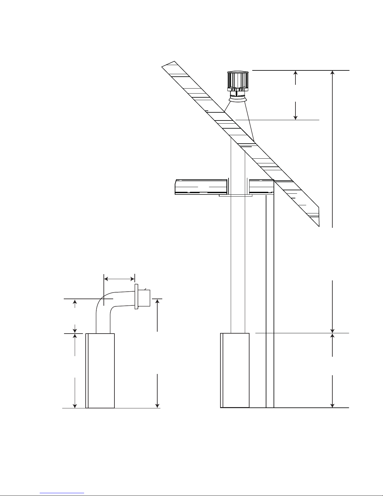
3.2 TYPICAL VENT INSTALLATION
9
16” MINIMUM
16 1/4”
MINIMUM
70 1/4”
24” MAXIMUM
3 FEET
MINIMUM
40 FEET
MAXIMUM
86 1/2”
MINIMUM
PLUS RISE*
70 1/4”
* See “VENTING” section
W415-1107 / 07.24.12
Page 10
10
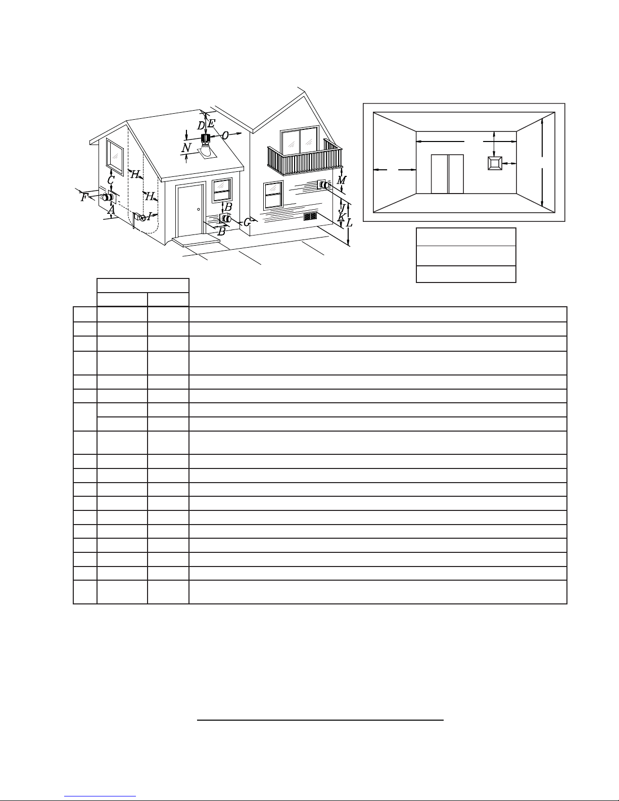
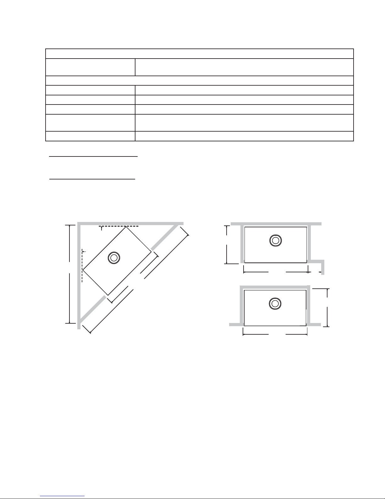
3.3 VENT TERMINAL CLEARANCES
COVERED BALCONY APPLICATIONS
Q
M
R
G
P
Q
R
R
MIN
MAX
MAX
= 3 feet
= 2 x
Q
feet
ACTUAL
INSTALLATIONS
CANADA U.S.A.
A 12” 12” Clearance above grade, veranda porch, deck or balcony.
B 12”
Δ
Δ
9”
Clearance to windows or doors that open.
C 12” * 12” * Clearance to permanently closed windows.
D 18” ** 18” **
Vertical clearance to ventilated soffi ts located above the terminal within a horizontal distance of 2’ from
the centerline of the terminal.
E 12” ** 12” ** Clearance to unventilated soffi t.
F 0” 0” Clearance to an outside corner wall.
G
H 3’ 3’ ****
0” *** 0” *** Clearance to an inside non-combustible corner wall or protruding non-combustible obstructions (chimney, etc.).
2” *** 2” *** Clearance to an inside combustible corner wall or protruding combustible obstructions (vent chase, etc.).
Clearance to each side of the centerline extended above the meter / regulator assembly to a maximum
vertical distance of 15’.
I 3’ 3’ **** Clearance to a service regulator vent outlet.
J 12” 9” Clearance to a non-mechanical air supply inlet to the building or a combustion air inlet to any other appliance.
K 6’ 3’ Clearance to a mechanical air supply inlet.
L 7’ ‡ 7’ **** Clearance above a paved sidewalk or paved driveway located on public property.
M 12” †† 12” **** Clearance under a veranda, porch, deck or balcony.
N 16” 16” Clearance above the roof.
O 2’ †* 2’ †* Clearance from an adjacent wall including neighbouring buildings.
P 8’ 8’ Roof must be non-combustible without openings.
Q 3’ 3’ See chart for wider wall dimensions.
R 6’ 6’
The terminal shall not be located less than 6 feet under a window that opens on a horizontal plane in a structure with three walls and a roof.
Δ
* Recommended to prevent condensation on windows and thermal breakage
** It is recommended to maximize the distance to vinyl clad soffi ts.
*** The periscope requires a minimum 18” clearance from an inside corner.
**** This is a recommended distance. For additional requirements check local codes.
† 3 feet above if within 10 feet horizontally.
‡ A vent shall not terminate where it may cause hazardous frost or ice accumulations on adjacent property surfaces.
†† Permitted only if the veranda, porch, or deck is fully open on a minimum of two sides beneath the fl oor.
†* Recommended to prevent recirculation of exhaust products. For additional requirements check local codes.
See chart for deeper wall dimensions. The terminal shall not be installed on any wall that has an opening between the terminal and the open side of the structure.
12.3B
W415-1107 / 07.24.12
Page 11
3.4 VENTING APPLICATION FLOW CHART
11
Horizontal Termination
Vertical rise is equal
to or greater than
the horizontal run
Horizontal run +
vertical rise to
maximum of 40 feet
3.5 DEFINITIONS
For the following symbols used in the venting calculations and examples are:
> - greater than
> - equal to or greater than
< - less than
< - equal to or less than
HT - total of both horizontal vent lengths (Hr) and offsets (Ho) in feet
HR - combined horizontal vent lengths in feet
HO - offset factor: .03 (total degrees of offset - 90°*) in feet
VT - combined vertical vent lengths in feet
Vertical rise is less
than horizontal run
Horizontal run +
vertical rise to
maximum of 24.75
feet
4.2 times the
vertical rise equal to
or greater than the
horizontal run
Vertical Termination
Vertical rise is equal
to or greater than
the horizontal run
Horizontal run +
vertical rise to
maximum of 40 feet
Vertical rise is less
than horizontal run
Horizontal run +
vertical rise to
maximum of 40 feet
3 times the vertical
rise equal to or
greater than the
horizontal run
13.1
14.1
3.6 ELBOW VENT LENGTH VALUES
FEET INCHES
1° 0.03 0.5
15° 0.45 6.0
30° 0.9 11.0
45° 1.35 16.0
90°* 2.7 32.0
* The fi rst 90° offset has a zero value and is shown in the formula as - 90°
15.1
W415-1107 / 07.24.12
Page 12
12
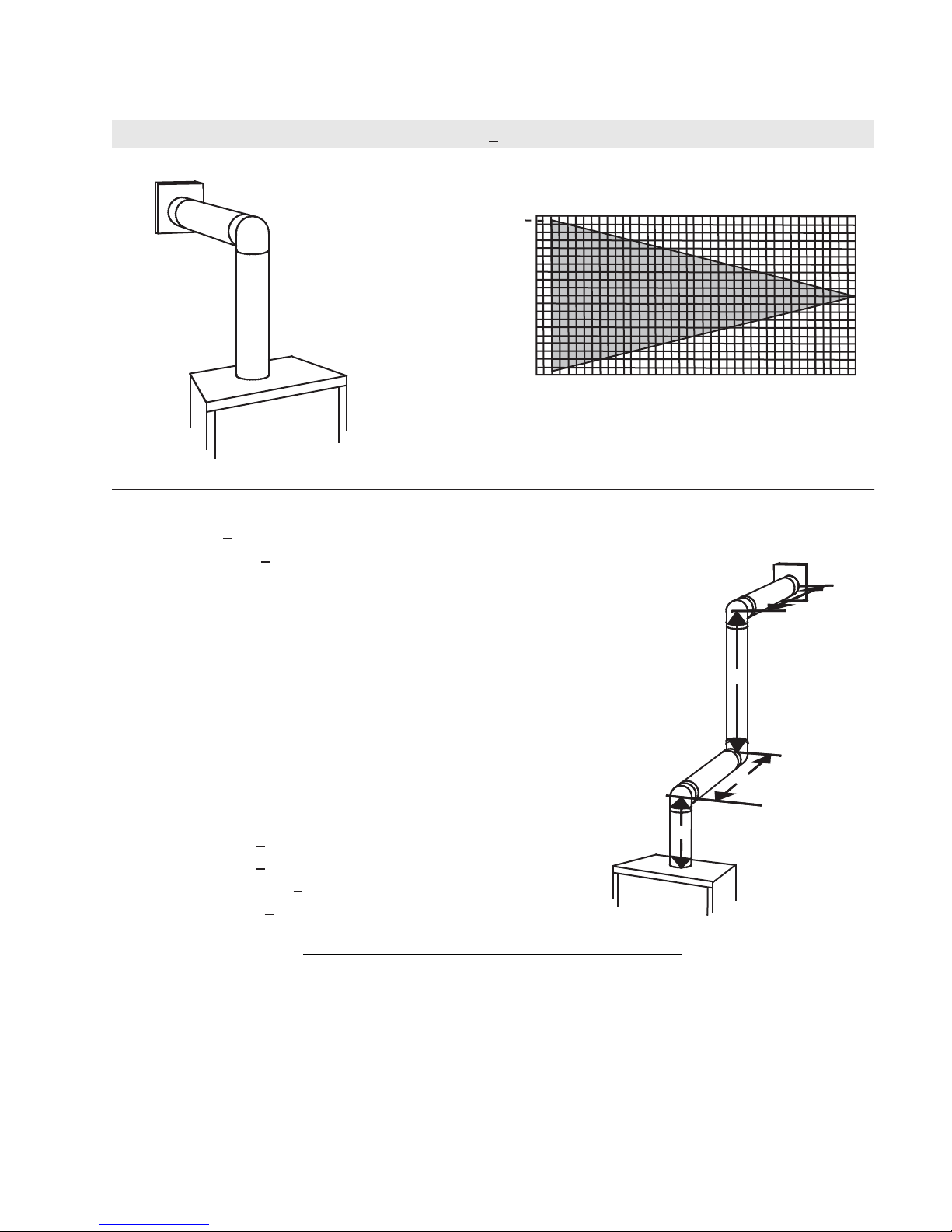
3.7 TOP EXIT HORIZONTAL TERMINATION
(HT) < (VT)
Simple venting confi guration (only one 90° elbow)
See graph to determine the required vertical
rise VT for the required horizontal run HT.
40
39
30
REQUIRED
VERTICAL
20
RISE IN
FEET VT
10
0
2.5 5 7.5 10 12.5 15
HORIZONTAL VENT RUN PLUS OFFSET IN
FEET H
T
The shaded area within the lines represents
acceptable values for HT and V
For vent confi gurations requiring more than one 90° elbow, the following formulas apply:
Formula 1: HT < V
T
Formula 2: HT + VT < 40 feet
Example:
V1 = 3 FT
90°
V2 = 8 FT
VT = V1 + V2= 3 FT + 8 FT = 11 FT
V
H1 = 2.5 FT
2
H2 = 2 FT
HR = H1 + H2 = 2.5 + 2 = 4.5 FT
HO = .03 (three 90° elbows - 90°) = .03 (270° - 90°) = 5.4 FT
HT = HR + HO = 4.5 + 5.4 = 9.9 FT
HT + VT = 9.9 + 11 = 20.9 FT
90°
90°
H
1
17.5 20
T
H
2
Formula 1: HT < V
T
9.9 < 11
Formula 2: HT + VT < 40 FT
20.9 < 40
Since both formulas are met, this vent confi guration is acceptable.
W415-1107 / 07.24.12
V
1
16.1A
Page 13
13
V
V
V
V
(HT) > (VT)
Simple venting configuration (only one 90° elbow)
REQUIRED
See graph to determine the required vertical rise VT for the
required horizontal run H
150
147”
100
.
T
VERTICAL
RISE IN
INCHES V
T
57”
50
19 1/2”
0
515
2’
10
12.5’
19.5’
20
HORIZONTAL VENT RUN PLUS OFFSET IN FEET H
T
The shaded area within the lines represents acceptable
values for HT and VT
For vent configurations requiring more than one 90° elbow, the following formulas apply:
< 4.2 V
Formula 1:
Formula 2: HT + V
H
T
T
< 24.75 feet
T
90°
H
1
H
2
Example:
= VT = 6 FT
1
H
= 3 FT
1
H
= 5 FT
2
H
= H
+ H
R
H
= .03 (two 90° elbows - 90°) = .03 (180° - 90°) = 2.7 FT
O
H
= H
T
H
+ V
T
= 3 + 5 = 8 FT
1
2
+ H
= 8 + 2.7 = 10.7 FT
R
O
= 10.7 + 6 = 16.7 FT
T
V
1
90°
Formula 1: HT < 4.2 V
4.2 VT = 4.2 x 6 = 25.2 FT
10.7 < 25.2
Formula 2: HT + V
16.7 < 24.75
Since both formulas are met, this vent configuration is acceptable.
Example:
= 4 FT
1
= 1.5 FT
2
= V
+ V
T
H
= 2 FT
1
H
= 1 FT
2
H
= 1 FT
3
H
= 1.5 FT
4
H
= H
R
H
= .03 (four 90° elbows - 90°) = .03 (360° - 90°) = 8.1 FT
O
H
= H
T
H
+ V
T
= 4 + 1.5 = 5.5 FT
1
2
+ H2 + H
1
+ H
R
= 13.6 + 5.5 = 19.1 FT
T
+ H4 = 2 + 1 + 1 + 1.5 = 5.5 FT
3
= 5.5 + 8.1 = 13.6 FT
O
Formula 1: HT < 4.2 V
4.2 VT = 4.2 x 5.5 = 23.1 FT
T
< 24.75 FT
T
T
90°
90°
90°
H
1
90°
V
1
V
H
H
2
3
H
4
2
13.6 < 23.1
Formula 2: HT + V
19.1 < 24.75
< 24.75 FT
T
Since both formulas are met, this vent configuration is acceptable.
16.1_2
W415-1107 / 07.24.12
Page 14
14
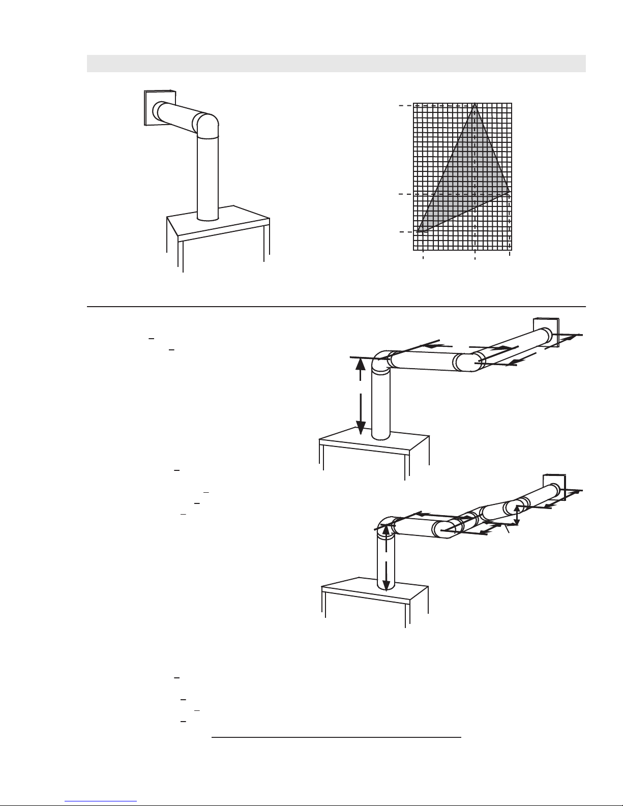
3.8 TOP EXIT VERTICAL TERMINATION
(HT) < (VT)
Simple venting configurations.
See graph to determine the required vertical rise V
required horizontal run HT.
40
30
REQUIRED
VERTICAL
20
RISE IN
FEET V
T
10
3
0
5101520
HORIZONTAL VENT RUN PLUS OFFSET IN FEET H
The shaded area within the lines represents acceptable
values for HT and VT
For vent configurations requiring one or more 90° elbows the following formulas apply:
Formula 1: H
Formula 2: HT + V
< V
T
T
< 40 feet
T
for the
T
T
Example:
V
= 5 FT
1
V
= 6 FT
2
V
= 10 FT
3
V
= V
+ V2 + V3 = 5 + 6 + 10 = 21 FT
T
1
H
= 8 FT
1
H
= 2.5 FT
2
H
= H
+ H
R
H
= .03 (four 90° elbows - 90°)
O
= .03 (360° - 90°) = 8.1 FT
H
= H
T
H
+ V
T
Formula 1: HT < V
18.6 < 21
Formula 2: HT + V
39.6 < 40
= 8 + 2.5 = 10.5 FT
1
2
+ H
= 10.5 + 8.1 = 18.6 FT
R
O
= 18.6 + 21 = 39.6 FT
T
T
< 40 FT
T
Since both formulas are met, this vent configuration is acceptable.
V
90°
1
90°
V
3
H
2
V
H
1
2
90°
90°
W415-1107 / 07.24.12
Page 15
15
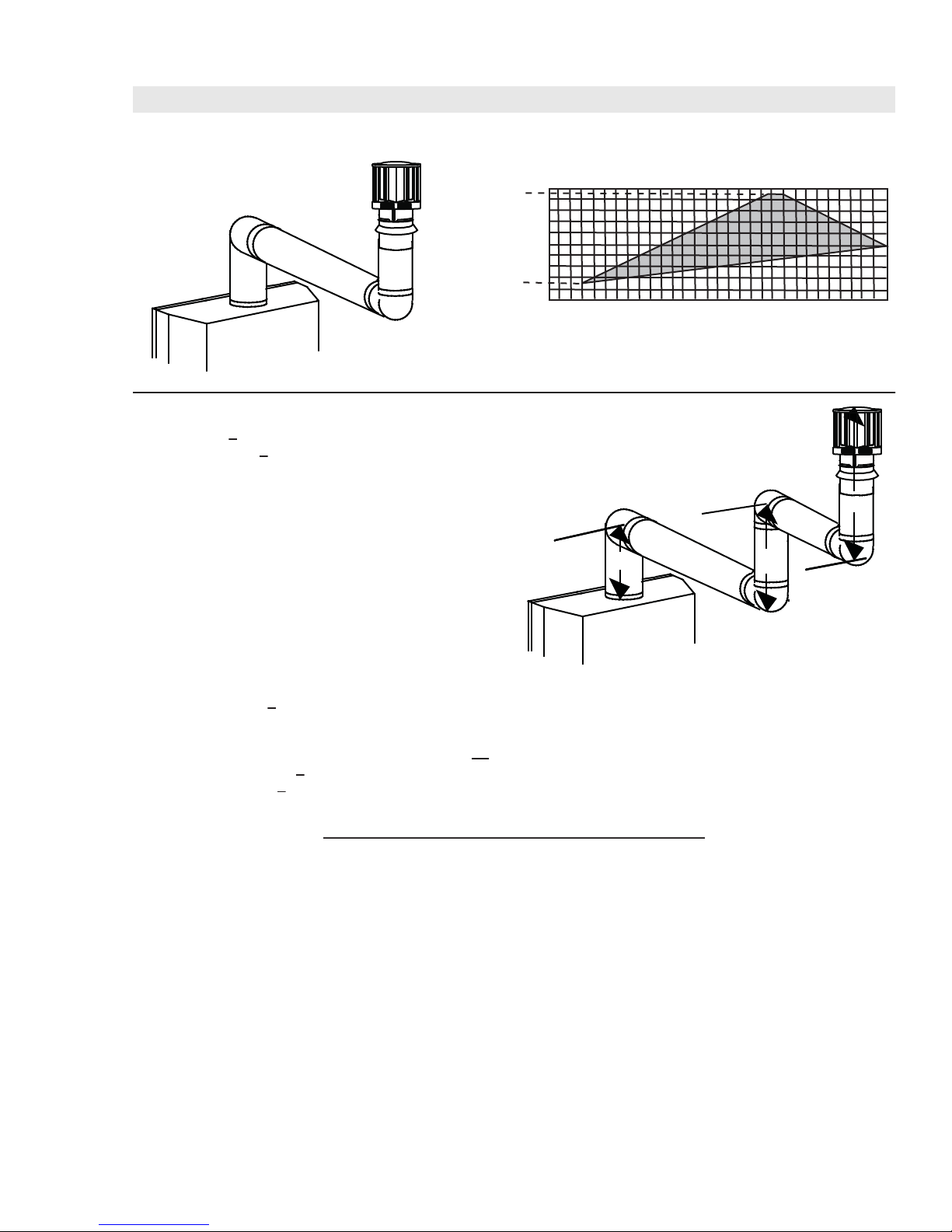
(HT) > (VT)
Simple venting configurations.
See graph to determine the required vertical rise V
required horizontal run H
20
19
REQUIRED
VERTICAL
RISE IN
FEET V
10
T
3
0
5101520
HORIZONTAL VENT RUN PLUS OFFSET IN FEET H
The shaded area within the lines represents acceptable
values for HT and VT
For vent configurations requiring more than two 90° elbows the following formulas apply:
Formula 1: H
Formula 2: HT + V
< 3V
T
T
< 40 feet
T
Example:
V
= 2 FT
1
V
= 1 FT
2
V
= 1.5 FT
3
V
= V
+ V2 + V3 = 2 + 1 + 1.5 = 4.5 FT
T
1
H
= 6 FT
1
H
= 2 FT
2
H
= H
+ H
R
H
= .03 (four 90° elbows - 90°)
O
= .03 (360° - 90°) = 8.1 FT
H
= H
T
H
+ V
T
= 6 + 2 = 8 FT
1
2
+ H
= 8 + 8.1 = 16.1 FT
R
O
= 16.1 + 4.5 = 20.6 FT
T
90°
H
V
1
1
90°
for the
.
T
H
V
2
T
25 30
V
2
T
3
90°
90°
Formula 1: HT < 3V
3VT = 3 x 4.5 = 13.5 FT
T
16.1 > 13.5
Since this formula is not met, this vent configuration is unacceptable.
Formula 2: HT + VT < 40 feet
20.6 < 40
Since only formula 2 is met, this vent configuration is unacceptable and a new appliance location or vent configuration will
need to be established to satisfy both formulas.
18.1_2A
W415-1107 / 07.24.12
Page 16
16
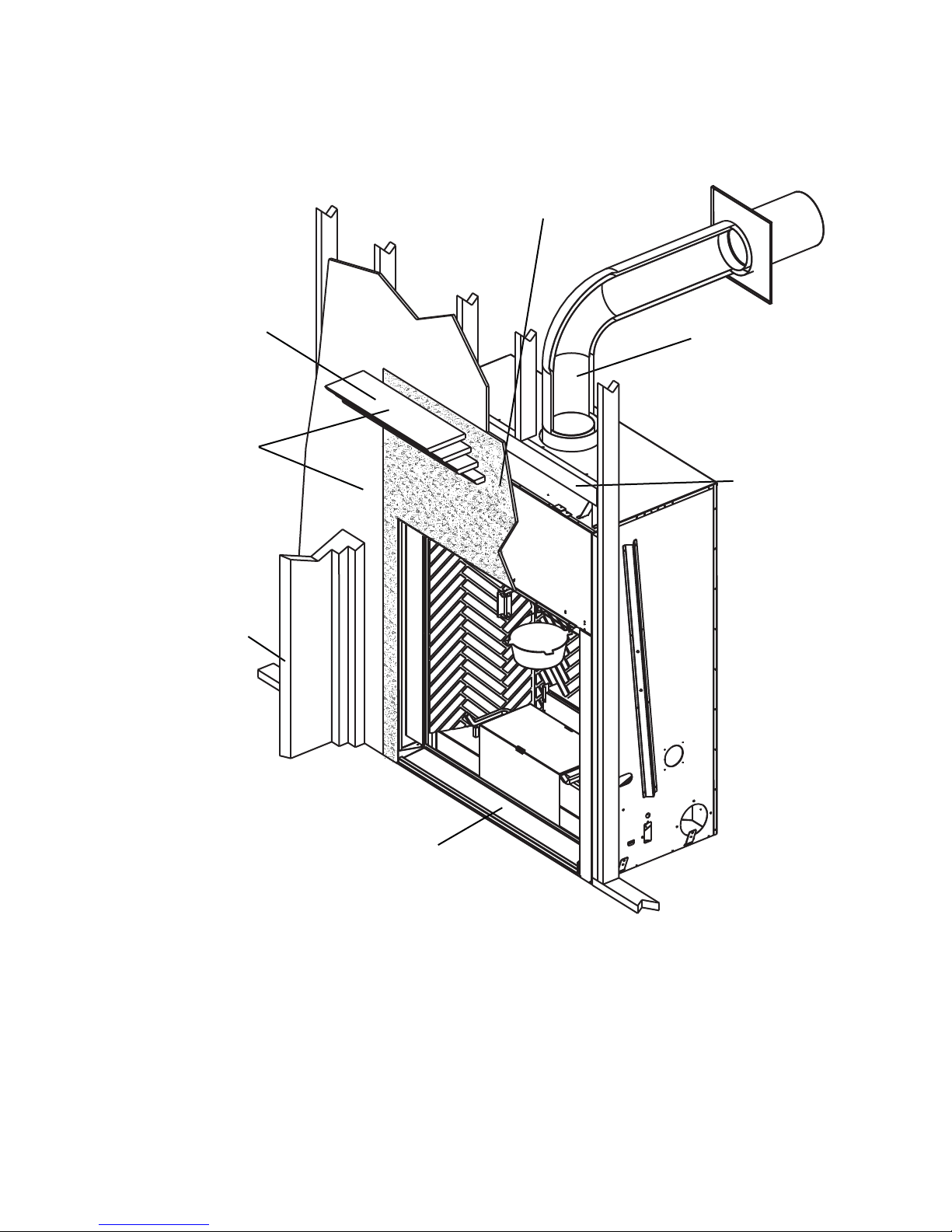
4.0 INSTALLATION
FOR SAFE AND PROPER OPERATION OF THE APPLIANCE, FOLLOW THE VENTING INSTRUCTIONS
ALL INNER EXHAUST AND OUTER INTAKE VENT PIPE JOINTS MAY BE SEALED USING EITHER RED
RTV HIGH TEMP SILICONE SEALANT W573-0002 (NOT SUPPLIED) OR BLACK HIGH TEMP MILL PAC
W573-0007 (NOT SUPPLIED) WITH THE EXCEPTION OF THE APPLIANCE EXHAUST FLUE COLLAR
IF USING PIPE CLAMPS TO CONNECT VENT COMPONENTS, 3 SCREWS MUST ALSO BE USED TO
ENSURE THE CONNECTION CANNOT SLIP OFF.
RISK OF FIRE, EXPLOSION OR ASPHYXIATION. IMPROPER SUPPORT OF THE ENTIRE VENTING
SYSTEM MAY ALLOW VENT TO SAG AND SEPARATE. USE VENT RUN SUPPORTS AND CONNECT
VENT SECTIONS PER INSTALLATION INSTRUCTIONS.
RISK OF FIRE, DO NOT ALLOW LOOSE MATERIALS OR INSULATION TO TOUCH THE VENT PIPE.
REMOVE INSULATION TO ALLOW FOR THE INSTALLATION OF THE ATTIC SHIELD AND TO
MAINTAIN CLEARANCES TO COMBUSTIBLES.
!
WARNING
EXACTLY.
WHICH MUST BE SEALED USING MILL PAC.
DO NOT CLAMP THE FLEXIBLE VENT PIPE.
68.2A
4.1 WALL AND CEILING PROTECTION
!
DO NOT FILL THE SPACE BETWEEN THE VENT PIPE AND ENCLOSURE WITH ANY TYPE OF
MATERIAL. DO NOT PACK INSULATION OR COMBUSTIBLES BETWEEN CEILING FIRESTOPS.
ALWAYS MAINTAIN SPECIFIED CLEARANCES AROUND VENTING AND FIRESTOP SYSTEMS.
INSTALL WALL SHIELDS AND FIRESTOPS AS SPECIFIED. FAILURE TO KEEP INSULATION OR
OTHER MATERIALS AWAY FROM VENT PIPE MAY CAUSE FIRE.
For clearances to combustible materials from the vent pipe, see “FRAMING” section.
WARNING
70.1
W415-1107 / 07.24.12
Page 17
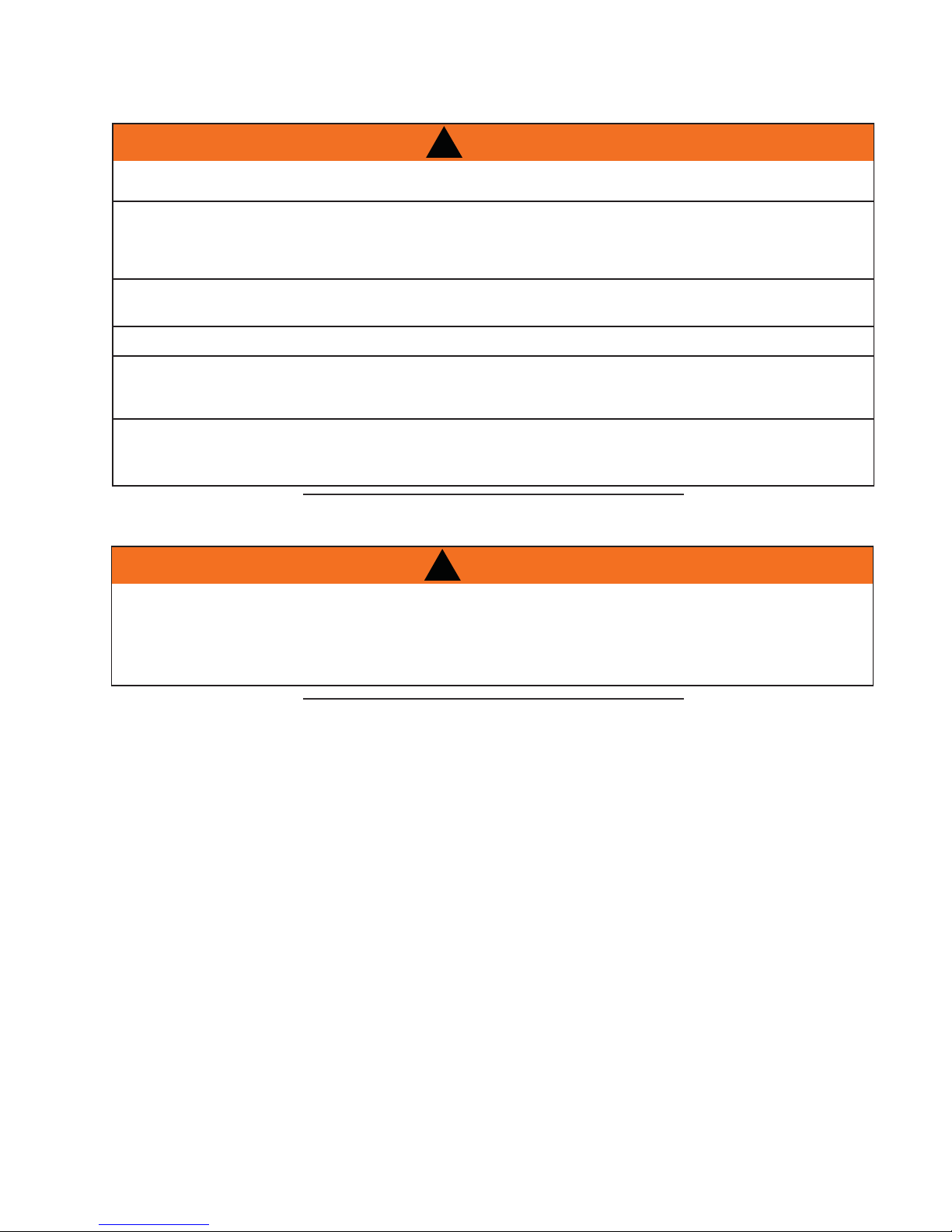
4.1.1 HORIZONTAL INSTALLATION
A
THE FIRESTOP ASSEMBLY MUST BE INSTALLED WITH THE VENT SHIELD TO THE TOP.
TERMINALS MUST NOT BE RECESSED INTO A WALL OR SIDING MORE THAN THE DEPTH OF THE
RETURN FLANGE OF THE MOUNTING PLATE.
This application occurs when venting through an exterior wall.
Having determined the correct height for the air terminal
location, cut and frame a hole in the exterior wall as
illustrated to accommodate the fi restop assembly.
Dry fi t the fi restop assembly before proceeding to
ensure the brackets on the rear surface fi t to the
inside surface of the horizontal framing.
The length of the vent shield may be cut shorter
for combustible walls that are less than 8 1/2” thick
but the vent shield must extend the full depth of the
combustible wall.
. Apply a bead of caulking (not supplied) around the corner edge of
the inside surface of the fi restop assembly, fi t the fi restop
assembly to the hole and secure using the 4 screws (supplied in your
manual baggie).
!
WARNING
CAULKING
FIRESTOP
SPACER
17
VENT
SHIELD
DETERMINE
THE
CORRECT
HEIGHT
FINISHING
MATERIAL
B. Once the vent pipe is installed in its fi nal position, apply high temperature sealant W573-0007 (not
supplied) between the pipe and the fi restop.
20.2
4.1.2 VERTICAL INSTALLATION
This application occurs when venting through a roof. Installation kits for
various roof pitches are available from your authorized dealer / distributor. See
accessories to order specifi c kits required.
A. Determine the air terminal location, cut and frame a square opening as
illustrated in the ceiling and the roof to provide the minimum 1“ clearance
between the vent pipe and any combustible material. Try to center the vent
pipe location midway between two joists to prevent having to cut them. Use
a plumb bob to line up the center of the openings. A vent pipe shield will
prevent any materials such as insulation, from fi lling up the 1” air space
around the pipe. Nail headers between the joist for extra support.
B. Apply a bead of caulking (not supplied) to the framework or to the Wolf
Steel vent pipe shield plate or equivalent (in the case of a fi nished
ceiling), and secure over the opening in the ceiling. A fi restop must be
placed on the bottom of each framed opening in a roof or ceiling that the
venting system passes through. Apply a bead of caulking all around and place a
fi restop spacer over the vent shield to restrict cold air from being drawn into the
room or around the fi replace. Ensure that both spacer and shield maintain the
required clearance to combustibles. Once the vent pipe is installed in its fi nal
position, apply sealant between the pipe and the fi restop assembly.
C. In the attic, slide the vent pipe collar down to cover up the open end of the shield and
tighten. This will prevent any materials, such as insulation, from fi lling up the 1” air space
around the pipe.
14 1/2" 14 1/2"
FIRESTOP
UNDERSIDE OF
JOIST
VENT PIPE
SHIELD
21.1
CAULKING
VENT
PIPE
SHIELD
VENT
PIPE
COLLAR
W415-1107 / 07.24.12
Page 18
18
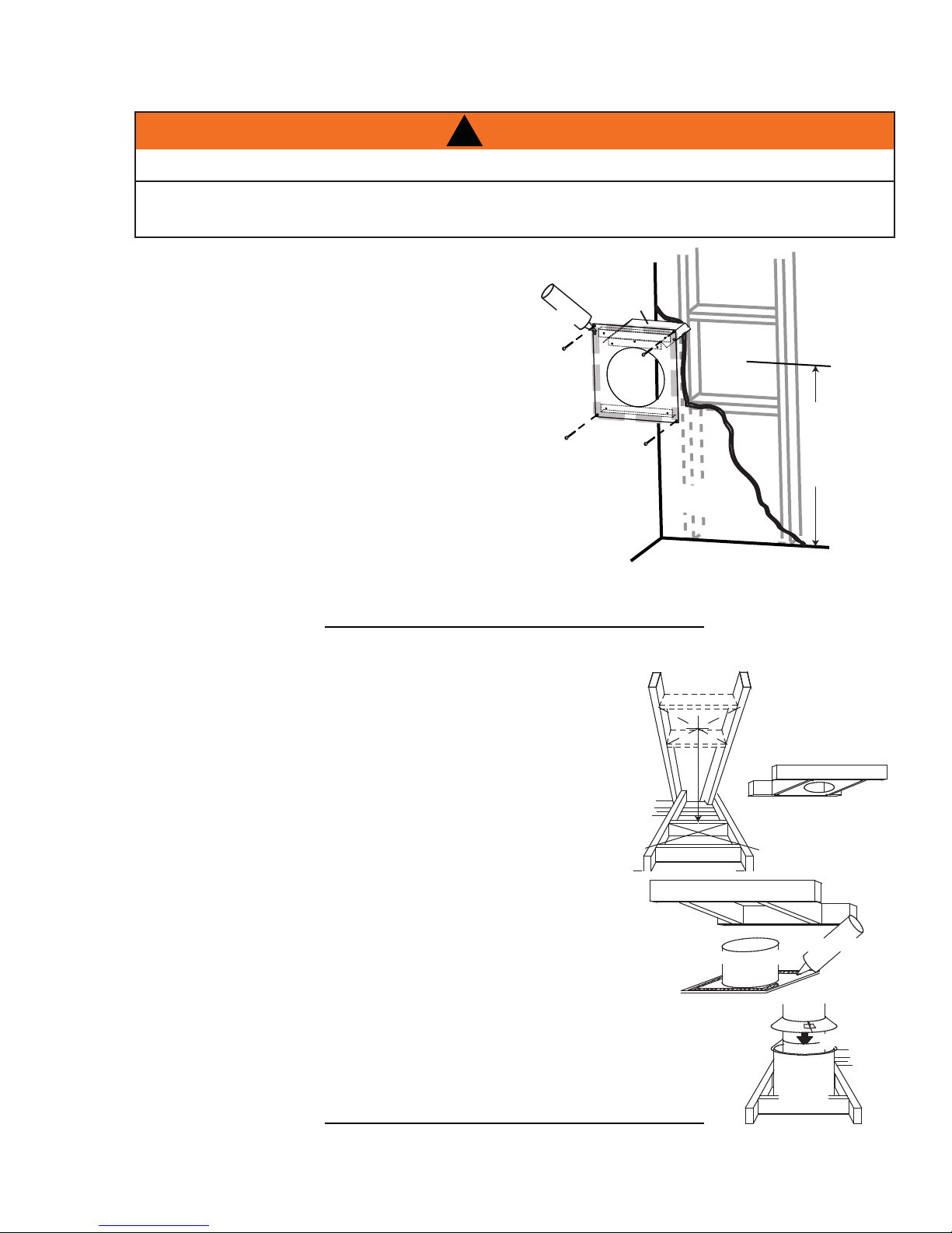
4.2 USING FLEXIBLE VENT COMPONENTS
!
WARNING
DO NOT ALLOW THE INNER FLEX PIPE TO BUNCH UP ON HORIZONTAL OR VERTICAL RUNS AND ELBOWS.
KEEP IT PULLED TIGHT.
SPACERS ARE ATTACHED TO THE INNER FLEX PIPE AT PREDETERMINED INTERVALS TO MAINTAIN AN EVEN
AIR GAP TO THE OUTER FLEX PIPE. THIS GAP IS REQUIRED FOR SAFE OPERATION. A SPACER IS REQUIRED
AT THE START, MIDDLE AND END OF EACH ELBOW TO ENSURE THIS GAP IS MAINTAINED. THESE SPACERS
MUST NOT BE REMOVED.
For safe and proper operation of the appliance, follow the venting
instructions exactly.
All inner fl ex pipe and outer fl ex pipe joints may be sealed using high
ELBOW
SPACERS
temperature sealant W573-0002 (not supplied) or the high temperature
sealant W573-0007 Mill Pac (not supplied). However, the high temperature
sealant W573-0007 Mill Pac (not supplied) must be used on the joint
connecting the inner fl ex pipe and the exhaust fl ue collar.
Use only approved fl exible vent pipe kits marked:
“Wolf Steel Approved Venting” as identifi ed
by the stamp only on the outer fl ex pipe.
4.2.1 HORIZONTAL AIR TERMINAL INSTALLATION
A. Stretch the inner fl ex pipe to the required length
taking into account the additional length needed for
the fi nished wall surface. Apply a heavy bead of the
high temperature sealant W573-0007 Mill Pac (not
supplied) to the inner sleeve of the air terminal. Slip
the vent pipe a minimum of 2” over the inner sleeve
of the air terminal and secure with 6 #8 screws.
B. Using the outer fl ex pipe, slide over the outer
combustion air sleeve of the air terminal and secure
with 6 #8 screws. Seal using high temperature
sealant W573-0002 (not supplied).
C. Insert the vent pipes through the fi restop
maintaining the required clearance to
combustibles. Holding the air terminal (lettering
in an upright, readable position), secure to the
exterior wall and make weather tight by sealing
with caulking (not supplied).
D. If more vent pipe needs to be used to reach
the fi replace, couple them together as
illustrated. The vent system must be supported
approximately every 3 feet for both vertical and
horizontal runs. Use noncombustible strapping to maintain the minimum 1” clearance to combustibles.
#10x2"
SCREWS
HI-TEMP
SEALANT
OUTER
FLEX PIPE
22.1
OUTER FLEX
PIPE
CAULKING
INNER FLEX
PIPE
2" OVERLAP
HI-TEMP
SEALANT
#8 X 1/2” SELF DRILLING
SCREWS & WASHERS
INNER COUPLER
OUTER COUPLER
OUTER
FLEX PIPE
INNER
FLEX PIPE
The air terminal mounting plate may be recessed into the exterior wall
or siding no greater than the depth of its return fl ange.
W415-1107 / 07.24.12
23.4A
Page 19
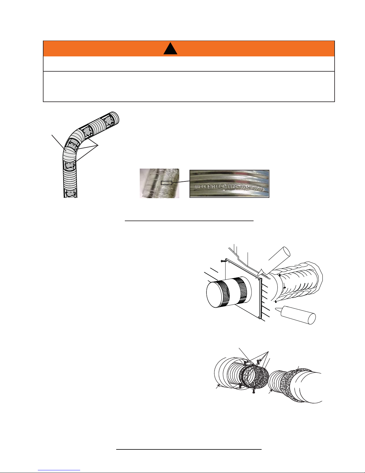
4.2.2 VERTICAL AIR TERMINAL INSTALLATION
!
WARNING
MAINTAIN A MINIMUM 2” SPACE BETWEEN THE AIR INLET BASE AND THE STORM COLLAR.
A. Fasten the roof support to the roof using the screws provided. The
roof support is optional. In this case the venting is to be adequately
supported using either an alternate method suitable to the
authority having jurisdiction or the optional roof support.
B. Stretch the inner fl ex pipe to the required length. Slip the
inner fl ex pipe a minimum of 2” over the inner pipe of the
air terminal connector and secure with 6 #8 screws. Seal
using a heavy bead of high temperature sealant W5730007 (not supplied).
19
C. Repeat using the outer fl ex pipe, using a heavy bead of
high temperature sealant W573-0002 (not supplied).
D. Thread the air terminal connector / vent pipe assembly down
through the roof. The air terminal must be positioned vertically
and plumb. Attach the air terminal connector to the roof support,
ensuring that the top of the air terminal is 16” above the highest
point that it penetrates the roof.
E. Remove nails from the shingles, above and to the sides of the
air terminal connector. Place the fl ashing over the air terminal
connector leaving a min. 3/4” of the air terminal connector showing
above the top of the fl ashing. Slide the fl ashing underneath the
sides and upper edge of the shingles. Ensure that the air terminal
connector is properly centred within the fl ashing, giving a 3/4”
margin all around. Fasten to the roof. Do not nail through the
lower portion of the fl ashing. Make weather-tight by sealing
with caulking. Where possible, cover the sides and top edges
of the fl ashing with roofi ng material.
F. Aligning the seams of the terminal and air terminal connector,
place the terminal over the air terminal connector making
sure the vent pipe goes into the hole in the terminal. Secure
with the three screws provided.
ROOF SUPPORT
AIR
TERMINAL
CONNECTOR
2”
INNER PIPE
HIGH
TEMPERATURE
SEALANT
INNER FLEX PIPE
OUTER FLEX PIPE
AIR INLE T
BASE
CAULKING
STORM COLLAR
G. Apply a heavy bead of weatherproof caulking 2” above the
fl ashing. Install the storm collar around the air terminal and
slide down to the caulking. Tighten to ensure that a weathertight seal between the air terminal and the collar is achieved.
H. If more vent pipe needs to be used to reach the fi replace see “HORIZONTAL
AIR TERMINAL INSTALLATION” section.
WEA THER
SEALANT
FLASHING
24.2
W415-1107 / 07.24.12
Page 20
20
A
4.2.3 APPLIANCE VENT CONNECTION
A. Install the inner fl ex pipe to the appliance. Secure with 3 screws
and fl at washers. Seal the joint and screw holes using the high
temperature sealant W573-0007 (not supplied).
B. Install the outer fl ex pipe to the appliance. Attach and seal
the joints using the high temperature sealant W573-0002 (not
supplied).
4.3 MOBILE HOME INSTALLATION
This appliance is also certifi ed to be installed as an OEM (Original Equipment Manufacturer) installation
in a manufactured home (U.S. only) or mobile home and must be installed in accordance with the
manufacturer’s instructions and the Manufactured Home Construction and Safety Standard, Title 24 CFR,
Part 3280, in the United States or the Mobile Home Standard, CAN/CSA Z240 MH Series, in Canada. This
appliance is only for use with the type(s) of gas indicated on the rating plate.
This Mobile/Manufactured Home Listed appliance comes factory equipped with a means to secure the unit. Built
in appliances are equipped with 1/4” diameter holes located in the front left and right corners of the base. Use #10
hex head screws, inserted through the holes in the base to secure. For free standing products contact your local
authorized dealer / distributor for the appropriate securing kit. For mobile home installations, the appliance must be
fastened in place. It is recommended that the appliance be secured in all installations. Always turn off the pilot and
the fuel supply at the source, prior to moving the mobile home. After moving the mobile home and prior to lighting
the appliance, ensure that the logs are positioned correctly.
#8 X 1/2”
SELF
DRILLING
SCREWS
2” OVERLAP
HIGH TEMP
SEALANT
28.1
This appliance is certifi ed to be installed in an aftermarket permanently located, manufactured (mobile)
home, where not prohibited by local codes.
This appliance is only for use with the type of gas indicated on the rating plate. This appliance is not
convertible for use with other gases, unless a certifi ed kit is used.
conversion kit is supplied with the mobile home appliance.
Conversion Kits
This appliance is fi eld convertible between Natural Gas (NG) and Propane (LP).
To convert from one gas to another consult your Authorized dealer/distributor.
29.1
W415-1107 / 07.24.12
Page 21

4.4 GAS INSTALLATION
RISK OF FIRE, EXPLOSION OR ASPHYXIATION. ENSURE THERE ARE NO IGNITION SOURCES SUCH AS
SUPPORT GAS CONTROL WHEN ATTACHING GAS SUPPLY PIPE TO PREVENT DAMAGING GAS LINE.
ALWAYS LIGHT THE PILOT WHETHER FOR THE FIRST TIME OR IF THE GAS SUPPLY HAS RUN OUT
WITH THE GLASS DOOR OPENED OR REMOVED. PURGING OF THE GAS SUPPLY LINE SHOULD BE
PERFORMED BY A QUALIFIED SERVICE TECHNICIAN. ASSURE THAT A CONTINUOUS GAS FLOW IS AT
THE BURNER BEFORE CLOSING THE DOOR. ENSURE ADEQUATE VENTILATION. FOR GAS AND
ELECTRICAL LOCATIONS, SEE “DIMENSION” SECTION.
ALL GAS CONNECTIONS MUST BE CONTAINED WITHIN THE APPLIANCE WHEN COMPLETE.
HIGH PRESSURE WILL DAMAGE VALVE. DISCONNECT GAS SUPPLY PIPING BEFORE TESTING GAS
VALVE SETTINGS HAVE BEEN FACTORY SET, DO NOT CHANGE.
Installation and servicing to be done by a qualifi ed installer.
A. Move the appliance into position and secure.
B. If equipped with a fl ex connector the appliance is designed to accept a 1/2” gas supply. Without the
connector it is designed to accept a 3/8” gas supply. The appliance is equipped with a manual shut off
valve to turn off the gas supply to the appliance.
C. Connect the gas supply in accordance to local codes. In the absence of local codes, install to the
current CAN/CSA-B149.1 Installation Code in Canada or to the current National Fuel Gas Code, ANSI
Z223.1 / NFPA 54 in the United States.
D. When fl exing any gas line, support the gas valve so that the lines are not bent or kinked.
E. The gas line fl ex-connector should be installed to provide suffi cient movement for shifting the burner
assembly on it’s side to aid with servicing components.
F. Check for gas leaks by brushing on a soap and water solution. Do not use open fl ame.
!
WARNING
SPARKS OR OPEN FLAMES.
LINE AT TEST PRESSURES ABOVE 1/2 PSIG.
21
30.1A
W415-1107 / 07.24.12
Page 22
22
5.0 FRAMING
IN ORDER TO AVOID THE POSSIBILITY OF EXPOSED INSULATION OR VAPOUR BARRIER COMING
IN CONTACT WITH THE APPLIANCE BODY, IT IS RECOMMENDED THAT THE WALLS OF THE
APPLIANCE ENCLOSURE BE “FINISHED” (IE: DRYWALL / SHEETROCK), AS YOU WOULD FINISH
ANY OTHER OUTSIDE WALL OF A HOME. THIS WILL ENSURE THAT CLEARANCE TO
DO NOT NOTCH THE FRAMING AROUND THE APPLIANCE STAND-OFFS. FAILURE TO MAINTAIN
AIR SPACE CLEARANCE MAY CAUSE OVER HEATING AND FIRE. PREVENT CONTACT WITH
SAGGING OR LOOSE INSULATION OR FRAMING AND OTHER COMBUSTIBLE MATERIALS. BLOCK
OPENING INTO THE CHASE TO PREVENT ENTRY OF BLOWN-IN INSULATION. MAKE SURE
WHEN CONSTRUCTING THE ENCLOSURE ALLOW FOR FINISHING MATERIAL THICKNESS TO
MAINTAIN CLEARANCES. FRAMING OR FINISHING MATERIAL CLOSER THAN THE MINIMUMS
LISTED MUST BE CONSTRUCTED ENTIRELY OF NON-COMBUSTIBLE MATERIALS. MATERIALS
CONSISTING ENTIRELY OF STEEL, IRON, BRICK, TILE, CONCRETE, SLATE, GLASS OR PLASTERS,
OR ANY COMBINATION THEREOF ARE SUITABLE. MATERIALS THAT ARE REPORTED AS PASSING
ASTM E 136, STANDARD TEST METHOD FOR BEHAVIOUR OF MATERIALS IN A VERTICAL TUBE
FURNACE AT 750°C AND UL763 SHALL BE CONSIDERED NON-COMBUSTIBLE MATERIALS.
MINIMUM CLEARANCE TO COMBUSTIBLES MUST BE MAINTAINED OR A SERIOUS FIRE HAZARD
THE APPLIANCE REQUIRES A MINIMUM ENCLOSURE HEIGHT. MEASURE FROM THE APPLIANCE
IF STEEL STUD FRAMING KITS WITH CEMENT BOARD ARE PROVIDED, THEY MUST BE
!
WARNING
RISK OF FIRE!
COMBUSTIBLES IS MAINTAINED WITHIN THE CAVITY.
INSULATION AND OTHER MATERIALS ARE SECURED.
COULD RESULT.
BASE.
INSTALLED.
71.1
WARNING
THE STANDOFFS HAVE
BEEN SHIPPED FLAT.
BEFORE FRAMING
ENSURE THE STANDOFFS
ARE BENT UP AND
SCREWED INTO PLACE.
ATTENTION ATENCIÓN
LES ESPACEURS SONT
EMBALLÉS À PLAT. AVANT DE
CONSTRUIRE L'OSSATURE,
ASSUREZ-VOUS QUE LES
ESPACEURS SONT PLIÉS
ET FIXÉS EN PLACE À
L'AIDE DE VIS.
LAS TRABAS PERMANECEN
PLANAS DURANTE EL ENVÍO.
ANTES DE LA INSTALACIÓN,
VERIFIQUE QUE LAS TRABAS
SE PLIEGUEN HACIA ARRIBA
Y SE ATORNILLEN
CORRECTAMENTE.
The can be installed with a rectangular opening.
It is best to frame your appliance after it is positioned and the
vent system is installed. Use 2x4’s and frame to local building
codes.
For convenience, the stand-offs have been shipped fl at.
Before framing, ensure the stand-offs are opened and
screwed in place.
It is not necessary to install a hearth extension, but the
appliance should be raised to be fl ush with either the hearth
or the fi nished fl oor.
When roughing in the appliance, raise the appliance to accommodate for the thickness of the fi nished fl oor
materials, i.e. tile, carpeting, hard wood, which if not planned for will interfere with the removal of the hearth
strip, which must be removed to access the fi rebox.
W415-1107 / 07.24.12
Page 23

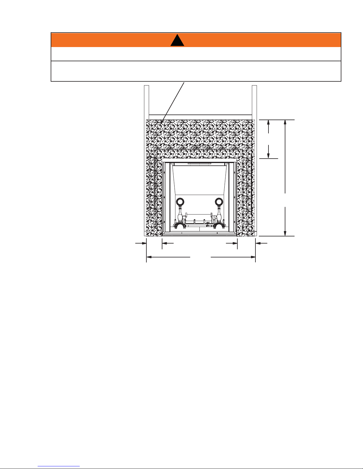
!
WARNING
DO NOT BUILD INTO THIS AREA - IT MUST BE LEFT CLEAR
TO PROVIDE ADEQUATE CLEARANCE FOR THE VENT IN
THIS 14” WIDE AREA CENTERED ALONG THE FRONT OF
THE FIREPLACE. NO COMBUSTIBLES ARE ALLOWED.
3 1/2”
MAXIMUM
23
96” *
MINIMUM
ENCLOSURE
HEIGHT
14” MINIMUM
3”
MAXIMUM
29 1/2” **
76 1/2” *
59 1/4” **
* Allow for fi nished fl oor and hearth thickness when setting these dimensions
** When constructing the enclosure allow for fi nishing material thickness to maintain clearances.
W415-1107 / 07.24.12
Page 24
24
59
1
/
4
"
1"
MIN
1"
MIN
116"
82"
59 1/4"
29 1/2"
29 1/2"
10"
MIN
59 1/4"
5.1 MINIMUM CLEARANCE TO COMBUSTIBLES
COMBUSTIBLE FRAMING:
Sides, back, bottom and top
of the appliance
COMBUSTIBLE FINISHING:
Rear 0”
Recessed depth 29 1/2”
Enclosure top 96” from base of appliance
Sides, bottom and top of vent
pipe*
Ceiling 96” from base of appliance
* HORIZONT AL VENT SECTIONS: A minimum clearance of 2” all around the vent pipe on all horizontal runs to combustibles is required except for clearances in appliance enclosures**. Use fi restop spacer assembly W010-1797 (supplied).
* VERTICAL VENT SECTIONS: A minimum of 1” all around the vent pipe on all vertical runs to combustibles is
required except for clearances in appliance enclosures**. Use fi restop spacer W615-0075 (not supplied).
** Horizontal and vertical sections require 5” and 9” clearance from combustibles, respectively. See “MINIMUM
ENCLOSURE CLEARANCES” section.
0” to stand-offs
2”
W415-1107 / 07.24.12
Page 25
25
!
WARNING
FACING AND/OR FINISHING MATERIAL MUST NEVER OVERHANG INTO THE APPLIANCE OPENING.
USE ONLY NON-COMBUSTIBLE MATERIAL SUCH AS CEMENT BOARD, CERAMIC TILE, MARBLE,
ETC. WHEN FINISHING TO THE APPLIANCE. DO NOT USE WOOD OR DRYWALL.
3
/4"
29
79 1/4"
5
1
/2"
5
1
/2"
60 3/4"
It is recommended that the walls of the appliance enclosure be fi nished. This would ensure that clearance to
combustibles is maintained within the cavity.
W415-1107 / 07.24.12
Page 26

26
5.2 MINIMUM ENCLOSURE CLEARANCES
!
WARNING
RISK OF FIRE!
THE FRONT OF THE APPLIANCE MUST BE FINISHED WITH ANY NON-COMBUSTIBLE MATERIALS
SUCH AS BRICK, MARBLE, GRANITE, ETC., PROVIDED THAT THESE MATERIALS DO NOT COVER
THE APPLIANCE OPENING.
TOP OF
FIREPLACE
96”
FIREPLACE
COMBUSTIBLE
46 1/2”
TOP OF
OPENING
COMBUSTIBLE
5”**
9”**
NON-
COMBUSTIBLE
NON-COMBUSTIBLE
BRICK
0” IF NONCOMBUSTIBLE FINISH-
2”
2”
ING IS USED SUCH AS
BRICK AND STONE
86 1/2”
MINIMUM
PLUS
RISE*
The requires a minimum inside enclosure height of 96” measured from the bottom of the appliance.
For temperature requirements, this area must be left unobstructed.
It is recommended that the enclosure be ventilated at the top and bottom to circulate the hot air with 2, 40”
square openings.
* See Venting Section
** Within the appliance enclosure a 9” clearance between the vertical vent run and the combustible materials
on the front facing of the enclosure is required. Similarly, a 5” clearance to combustible materials from the top
of the horizontal vent run is required. All other clearances within the enclosure, including where the vent pipe
exits the enclosure are subject to 2” for horizontal and 1” for vertical.
W415-1107 / 07.24.12
1”
IMPORTANT:
Page 27
0
34 7
8
9
12 56
7
H
E
I
G
H
T
M
A
N
T
E
L
MANTEL DEPTH
5
6
4
3
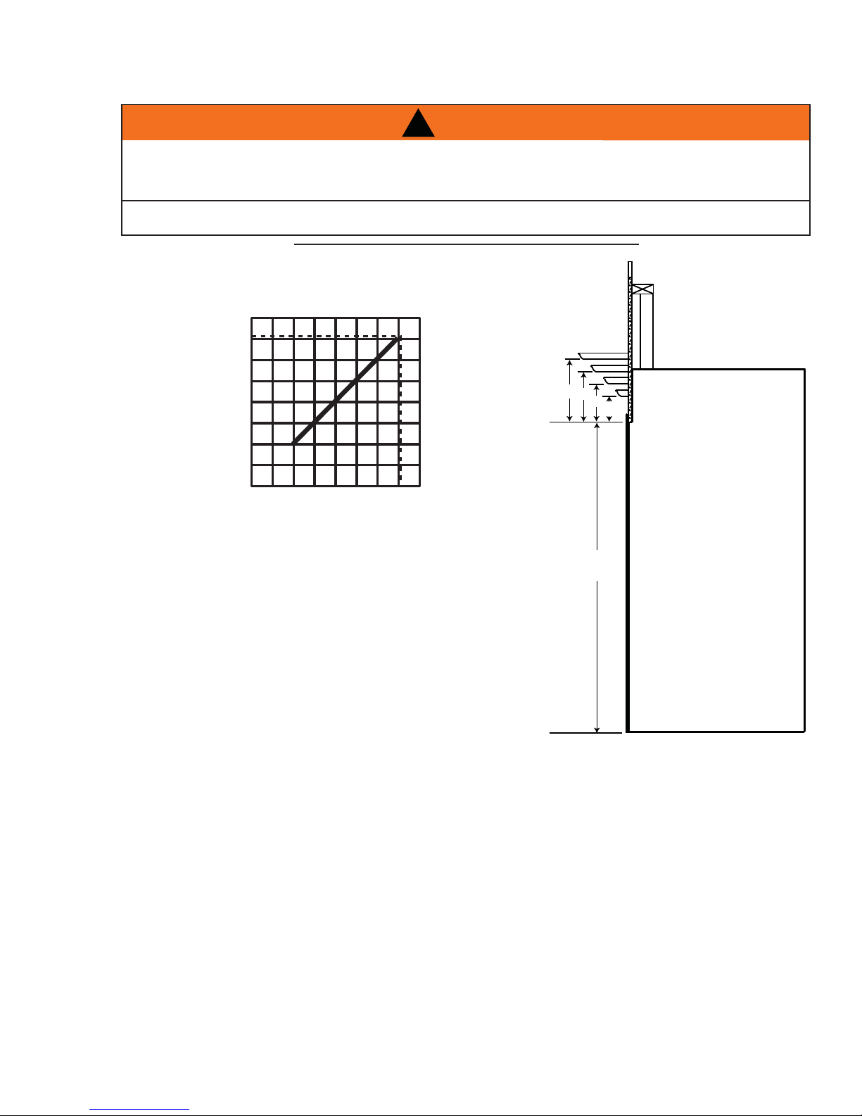
5.3 MINIMUM MANTEL CLEARANCES
RISK OF FIRE, MAINTAIN ALL SPECIFIED AIR SPACE CLEARANCES TO COMBUSTIBLES. FAILURE
TO COMPLY WITH THESE INSTRUCTIONS MAY CAUSE A FIRE OR CAUSE THE APPLIANCE TO
OVERHEAT. ENSURE ALL CLEARANCES (I.E. BACK, SIDE, TOP, VENT, MANTEL, FRONT, ETC.) ARE
CLEARLY MAINTAINED.
WHEN USING PAINT OR LACQUER TO FINISH THE MANTEL, THE PAINT OR LACQUER MUST BE
HEAT RESISTANT TO PREVENT DISCOLOURATION.
Combustible mantel clearance can vary according to the mantel depth.
Use the graph to help evaluate the clearance needed.
!
WARNING
27
73.1
8” MANTEL
6”
10”
8”
TOP OF
FIREPLACE
OPENING
49 1/2”
6”
TOP OF
FIREPLACE
4”
2”
4”
W415-1107 / 07.24.12
Page 28
28
6.0 ELECTRICAL CONNECTION
!
WARNING
DO NOT USE THIS APPLIANCE IF ANY PART HAS BEEN UNDER WATER. CALL A QUALIFIED
SERVICE TECHNICIAN IMMEDIATELY TO HAVE THE APPLIANCE INSPECTED FOR DAMAGE TO THE
ELECTRICAL CIRCUIT.
RISK OF ELECTRICAL SHOCK OR EXPLOSION. DO NOT WIRE 110V TO THE VALVE OR TO THE
APPLIANCE WALL SWITCH. INCORRECT WIRING WILL DAMAGE CONTROLS.
ALL WIRING SHOULD BE DONE BY A QUALIFIED ELECTRICIAN AND SHALL BE IN COMPLIANCE
WITH LOCAL CODES. IN THE ABSENCE OF LOCAL CODES, USE THE CURRENT CSA22.1 CANADIAN
ELECTRIC CODE IN CANADA OR THE CURRENT NATIONAL ELECTRIC CODE ANSI/NFPA NO. 70 IN
THE UNITED STATES.
ALWAYS LIGHT THE PILOT WHETHER FOR THE FIRST TIME OR IF THE GAS SUPPLY HAS RAN OUT,
WITH THE GLASS DOOR OPENED OR REMOVED.
If access to the control area is necessary before installation, remove the access panel. Located along the right
side of fi rebox.
69.2
The access panel must be re-installed before operating the appliance.
It is necessary to hard wire this appliance.
Permanently framing the appliance with an enclosure, requires the appliance junction box to be hard wired.
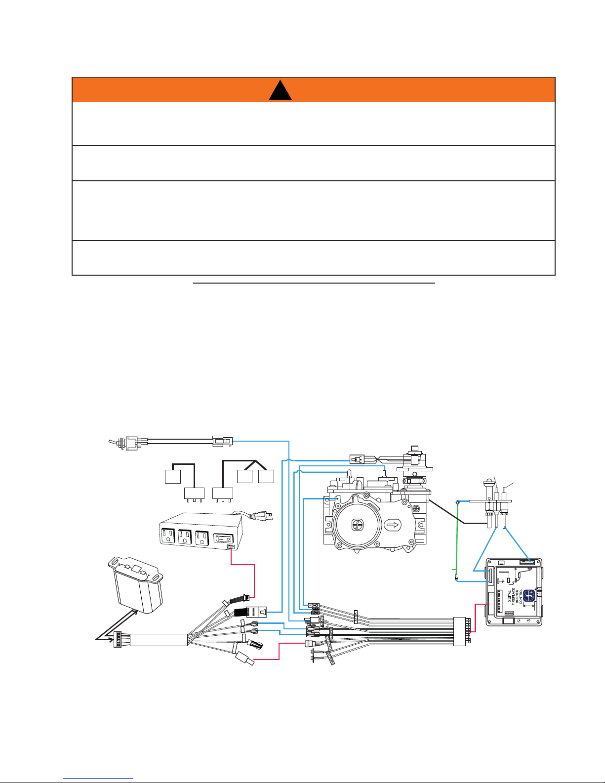
ACS/IPI Switch
Spark Electrode
Fan
120V OUT
FAN
Control Module
Receiver
AUX OUT
POWER
COM
Night Lights
Valve
Electronic Modulation
EI
Pilot
Pilot
Ground
Wire
Flame
Sensor
Wire
Harness
Plug
W415-1107 / 07.24.12
Wire Harness
IPI Board
Wire Harness Assembly
Page 29

6.1 RECEPTACLE WIRING DIAGRAM
29
ELECTRICAL BOX
(BLACK)
3 PRONG
WIRE
NUTS
RECEPTACLE
(WHITE)
GROUND
(GREEN)
6.2 OPTIONAL BLOWER INSTALLATION
See separate instructions accompanying the blower assembly.
L1 (BLACK)
GROUND
(GREEN)
L2 (WHITE)
CABLE
CONNECTOR
SCREW
ELECTRICAL
BOX COVER
W415-1107 / 07.24.12
Page 30

30
7.0 FINISHING
NEVER OBSTRUCT THE FRONT OPENING OF THE APPLIANCE.
THE FRONT OF THE APPLIANCE MUST BE FINISHED WITH ANY NON-COMBUSTIBLE MATERIALS
SUCH AS BRICK, MARBLE, GRANITE, ETC., PROVIDED THAT THESE MATERIALS DO NOT GO
DO NOT STRIKE, SLAM OR SCRATCH GLASS. DO NOT OPERATE APPLIANCE WITH GLASS
FACING AND/OR FINISHING MATERIAL MUST NEVER OVERHANG INTO THE APPLIANCE OPENING.
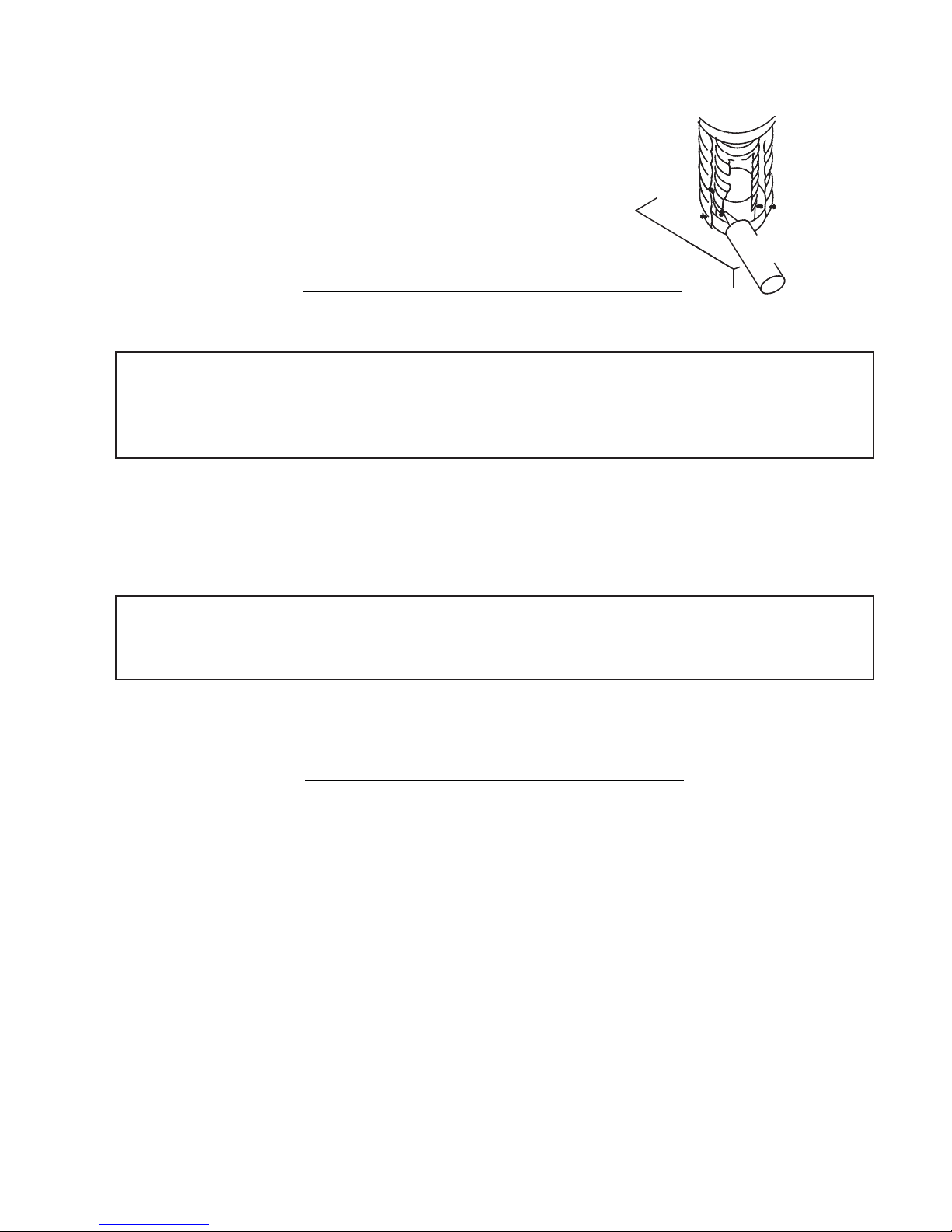
7.1 DOOR REMOVAL
GLASS MAY BE HOT, DO NOT TOUCH GLASS UNTIL COOLED.
THE DOOR LATCHES ARE PART OF A SAFETY SYSTEM AND MUST BE PROPERLY ENGAGED. DO
NOT OPERATE THE APPLIANCE WITH LATCHES DISENGAGED.
!
WARNING
RISK OF FIRE!
BELOW THE SPECIFIED DIMENSION AS ILLUSTRATED.
REMOVED, CRACKED, BROKEN OR SCRATCHED.
!
WARNING
72.1A
FACING AND/OR FINISHING MATERIALS MUST NOT INTERFERE WITH AIR FLOW THROUGH AIR
OPENINGS, LOUVRES OPENINGS, OPERATION OF LOUVRES OR DOORS OR ACCESS FOR
SERVICE. OBSERVE ALL CLEARANCES WHEN APPLYING COMBUSTIBLE MATERIALS.
BEFORE DOOR IS REMOVED TURN THE APPLIANCE OFF AND WAIT UNTIL APPLIANCE IS COOL TO
THE TOUCH. DOORS ARE HEAVY AND FRAGILE SO HANDLE WITH CARE.
75.1
Before the glass door can be removed, the control doors must be opened
and the hearth strip and screen assembly must be removed.
CONTROL DOORS
LOG SHIPPING
BRACKET
HEARTH STRIP
RETAINER
W415-1107 / 07.24.12
Page 31

With the control doors pulled open, you can now lift the hearth strip up and
away from the front of the appliance. The curtain assembly can be removed
by lifting the rod out from the three hooks at the top inside edge of the door
opening.
The glass door is secured to the fi rebox with 10 latches. 3 on each side, and
4 across the top.
A. Pull the handle of the latch forward, then lift the hooks out from the
slot in the door frame to release the top and sides of the door.
B. Lift the door out from the retainer along the bottom of the door.
NOTE: We recommend 2 people remove door due to size and
weight.
C. Pull the bottom edge of the door out from the appliance until the top
will pivot forward. Handle carefully as the door is extremely heavy.
31
HOOKS
ROD
SCREWS
W415-1107 / 07.24.12
Page 32

32
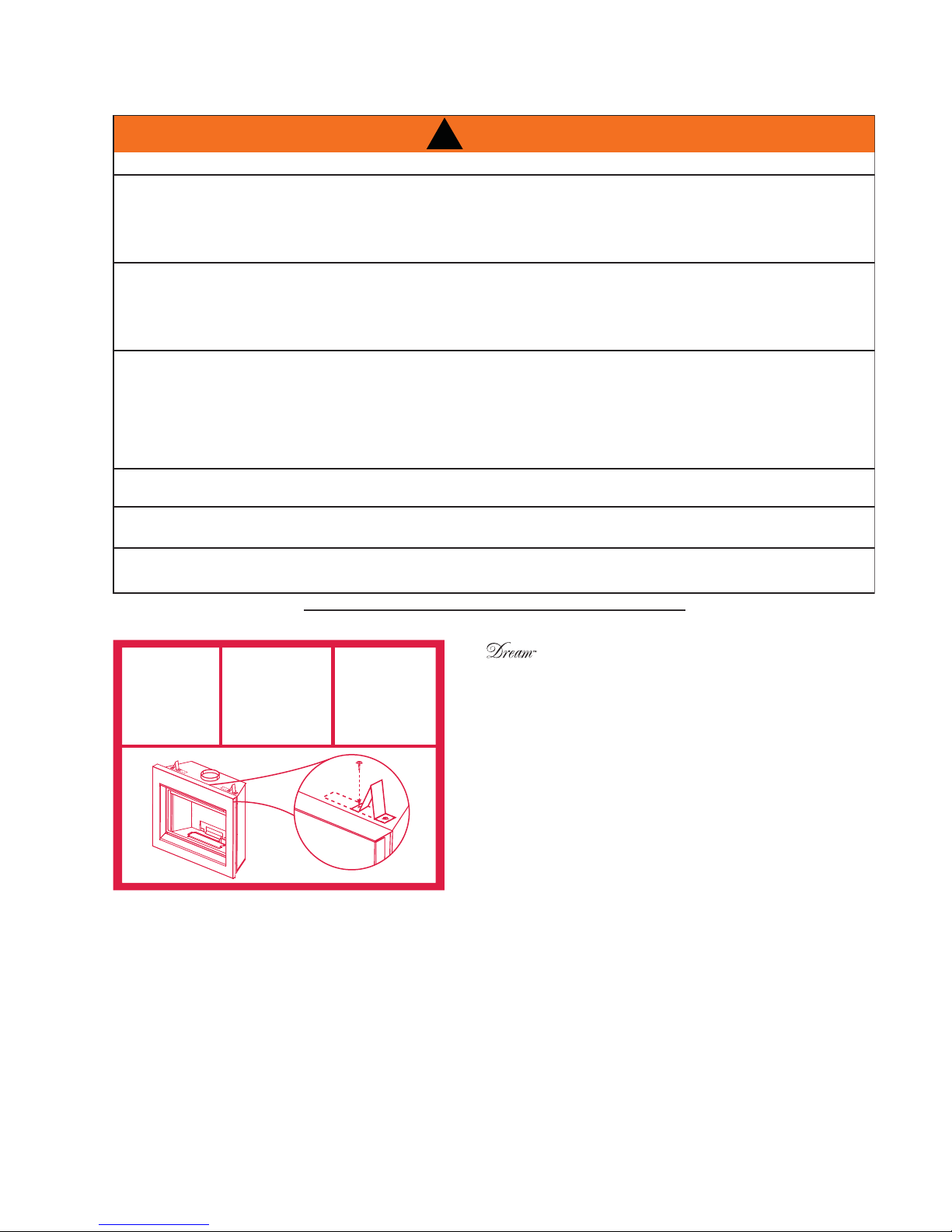
7.2 LOG SHIPPING BRACKET
Before installing the logs, you must fi rst remove the log shipping
bracket. Remove the two screws holding the shipping bracket in place.
Lift up to remove. Discard once removed. Replace the screws to seal
the fi rebox.
7.3 BRICK PANEL INSTALLATION
Brick panels are shipped separate from appliance due to the brittle material of the bricks, care must be taken
not to bend or force them into place.
When shipped, the brick panels range in varying shades of Sandstone. During initial use, the panels will
darken temporarily. The appearance of the panels will permanently lighten in color with use.
LOG
SHIPPING
BRACKET
REMOVE
SCREWS
INSTALL PANELS IN THE FOLLOWING ORDER:
6
6
3
3
1
2
1
2
4
5
4
5
W415-1107 / 07.24.12
Page 33

RETAINER
33
Secure the Left Panel and Right Panel using
6
the retainers located in the top left and right corners
of the fi rebox.
To install the Front Left , Centre , and Right
9
Hearth Panels you must fi rst remove one of the Right
or Left End Hearth Retainers.
END HEARTH RETAINERS
9
9
10
10
11
7.4 ANDIRON PLACEMENT
Andirons are packaged separately inside the appliance and must be installed prior
to the log installation. Place the Andiron on the Andiron brackets located at the front
of the appliance lining up the holes. Secure using the screws provided. Repeat on
other side.
10
11
8
7
11
7
8
8
W415-1107 / 07.24.12
Page 34

34
7.5 LOG PLACEMENT
FAILURE TO POSITION THE LOGS IN ACCORDANCE WITH THESE DIAGRAMS OR FAILURE TO USE
ONLY LOGS SPECIFICALLY APPROVED WITH THIS APPLIANCE MAY RESULT IN PROPERTY
LOGS MUST BE PLACED IN THEIR EXACT LOCATION IN THE APPLIANCE. DO NOT MODIFY THE
PROPER LOG POSITIONS, SINCE APPLIANCE MAY NOT FUNCTION PROPERLY AND DELAYED
THE LOGS ARE FRAGILE AND SHOULD BE HANDLED WITH CARE.
PHAZER™ logs and glowing embers, exclusive to Wolf Steel Ltd. fi replaces, provide a unique and realistic
glowing effect that is different in every installation. Take the time to carefully position the glowing embers for a
maximum glowing effect. Log colors may vary. During the initial use of the appliance, the colors will become
more uniform as color pigments burn in during the heat activated curing process.
1
!
WARNING
DAMAGE OR PERSONAL INJURY.
IGNITION MAY OCCUR.
76.1A
A. Center the rear
log (#1) behind
the rear burner
and onto the log
support.
6
E. Place the small
end of log#6 into
the front notch
of log#4. Place
the locating hole
in the large end
of log#6 onto the
locating pin on
top of log#2.
3
B. Place log#2 and
log#3 onto the
locating pins.
The logs should
sit fl at on the
burner.
F. Place the pin in
log #7 in the hole
in log #6. The log
should sit in the
notch on log #2
and the bottom
should rest along
the right side of
the Andiron.
2
4
C. Place the locating
hole on the underside of log#4 onto
the locating pin on
top of log#3. The
notch at the opposite end of log#4
sits on the third
grate post in from
the right side.
8
7
G. Place the large
end of log#8 into
the rear notch of
log#4.
The small branch
of log#8 sits in
the notch located
on top of log#1.
5
D. Place the small
branch of log#5
into the notch on
log#3. The notches
on the bottom edge
of log #5 should
sit on the fi rst and
second grate posts
from the left.
10
9
H. Place log#9 onto the
grate as though it
had burnt off log#5.
Place log#10 onto
the locating pin on
log#1. Again, log#10
should be aligned as
though it has burnt
off of log#7.
W415-1107 / 07.24.12
Page 35

7.6 CHARCOAL EMBERS
Randomly place the charcoal embers along the front and sides of the log support tray in a realistic manner.
Fine dust found in the bottom of the bag should not be used.
NOTE: Charcoal embers are not to be placed on the burner.
7.7 VERMICULITE
Sprinkle vermiculite around the charcoal embers.
NOTE: Vermiculite is not to be placed on the burner.
7.8 GLOWING EMBERS
Tear the embers into pieces and place along the front row of ports covering all of the burner area in front of
the small logs. Care should be taken to shred the embers into thin, small irregular pieces as only the exposed
edges of the fi bre hairs will glow. The ember material will only glow when exposed to direct fl ame; how-
ever, care should be taken to not block the burner ports.
Blocked burner ports can cause an incorrect fl ame pattern, carbon deposits and delayed ignition. PHAZERTM
logs glow when exposed to direct fl ame. Use only certifi ed "glowing embers" and PHAZERTM logs available
from your authorized dealer / distributor.
35
32.1
33.1
W415-1107 / 07.24.12
Page 36

36
8.0 REMOTE AND VALVE ACCESS
The control area can be accessed either through the control door or through the access panel inside the fi re-
box. The bulkhead fi ttings that are part of the gas supply to the burners can be accessed through the bulkhead
access plate.
8.1 INNER ACCESS PANEL
Follow the door removal instructions. Remove the right side brick panel. Remove the four screws from the inner access panel.
NOTE: A new gasket will be required, when re-installing the access panel, see “REPLACEMENTS” section.
8.2 BULKHEAD ACCESS PLATE
Follow the door removal instructions. Remove the
right side brick panel and hearth pad. Remove the
four screws from the bulkhead access panel.
NOTE: A new gasket will be required, when reinstalling the bulkhead access panel, see “REPLACEMENTS” section.
8.3 REMOTE RECEIVER REMOVAL
A. Open the right control door by pulling bottom portion away from
magnet catch.
B. Remove the hearth strip by lifting up and away from appliance.
C. Remove the receiver by pulling the left side of the plate away from the
bracket.
D. Once disengaged pull the wiring harness out from the back of receiver.
BULKHEAD
ACCESS
PANEL
GASKET
W415-1107 / 07.24.12
Page 37

8.4 CONTROL MODULE REMOVAL
A. Remove access panel from inside the
fi rebox.
B. Unplug the control module from the junction
box.
C. Pull up on the control module being held
down with Velcro and disconnect the plugs
(fan, aux). Remove wiring harness from the
front of the casing.
D. Install the new control module, see
“ELECTRICAL CONNECTION” section.
MAINS VOLTAGE
SUPPLY CORD
MODULE ON/OFF SWITCH
COMMUNICATION BUS (3 PIN)
FAN OUTLET
CONSTANTLY POWERED 120V OUTLET
120V AUX OUTLET
37
INNER ACCESS
PANEL
WING NUT
VALVE
SLOT
RECEIVER
SPARK MODULE
8.5 VALVE REMOVAL
The valve on The is piped with two fl ex connectors (one inlet, one outlet). It can be removed or pulled
forward for service.
A. Turn gas off.
B. Open right control door.
C. Remove the wing nut and pivot the valve out from the slot at the bottom of the valve.
D. Slowly pull the valve through the control door being careful not to kink the gas lines or wires.
E. Disconnect inlet/outlet fl ex connectors, wires and thermocouple.
F. Remove screws securing gas valve to the mounting bracket.
W415-1107 / 07.24.12
Page 38

38
A
9.0 OPERATION
IF YOU DO NOT FOLLOW THESE INSTRUCTIONS EXACTLY, A FIRE OR EXPLOSION MAY RESULT
CAUSING PROPERTY DAMAGE, PERSONAL INJURY OR LOSS OF LIFE.
!
WARNING
ALWAYS LIGHT THE PILOT WHETHER FOR THE FIRST TIME OR IF THE GAS SUPPLY HAS RUN OUT WITH
THE GLASS DOOR OPENED OR REMOVED.
9.1 GENERAL TRANSMITTER LAYOUT
TRANSMISSION
THERMOSTAT
OFF/ON/SMART
CHILD SAFETY
LOCK OUT
LOW BATTERY
ALARM
ROOM
TEMPERATURE
6
TEMPERATURE SET POINT/ LEVEL/ STATUS
AUX. OUTPUT
FANFLAME
35.1
9.2 APPLIANCE OPERATION
. Install 4 AA batteries into the receiver battery bay as indicated on the battery cover (+/-). (Only required
as back up to household electricity).
B. Place the 3 position slider switch of the receiver in the “Remote” position.
C. Using the end of a paper clip, or other similar object, insert the end of the paper clip into the hole
marked “PRG” on the receiver front cover. The receiver will “beep” three (3) times to indicate that it is
ready to synchronize with the transmitter.
D. Install the 3 AAA batteries in the transmitter battery bay, located on the base of the transmitter.
With the batteries already installed in the transmitter, push the “ON” button. The receiver will “beep”
four times to indicate the transmitter’s command is accepted and set to the particular code of that
transmitter. The system is now initialized.
35.2A
W415-1107 / 07.24.12
Page 39

9.3 HAND HELD REMOTE OPERATIONS
A
A
. Press the ON/OFF key on the transmitter. The transmitter
display will show all active icons on the screen. A single
“beep” from the receiver will confi rm reception of the
command.
9.4 TEMPERATURE DISPLAY
. With the system in the “OFF” position, press the
Thermostat Key and the Mode Key at the same
time to change from degrees F to C.
73
39
BLUE LCD DISPLAY
ON/OFF KEY
THERMOSTAT KEY
UP/DOWN
ARROW KEY
MODE KEY
35.4
°F
°C
23
B. Look at the LCD screen on the Transmitter to
verify that a C or F is visible to the right of the
Room Temperature display.
9.5 ROOM THERMOSTAT
The remote transmitter can operate as a room thermostat.
The thermostat can be set to a desired temperature to control the
comfort level in the room.
A. Press the Thermostat Key. The LCD display on the
Transmitter will show that the room is “ON” and the set
temperature is now displayed.
B. To adjust the set temperature, press the Up/Down Arrow
Keys until the desired set temperature is displayed on the
LCD screen of the Transmitter.
35.5
ROOM TEMPERATURE
ON
68
SET TEMPERATURE
35.6
°F
76
W415-1107 / 07.24.12
Page 40

40
A
9.6 SMART THERMOSTAT
The Smart Thermostat function adjusts the fl ame height according to the difference
between the set temperature and the actual room temperatures. As the room
temperature gets closer to the set point the Smart Function will automatically adjust
the fl ame down.
ON
SMART
°F
76
. Press the thermostat key until the word “SMART” appears to the right of the
temperature bulb graphic.
B. To adjust the set temperature, press the Up/Down arrow keys until the
desired set temperature is displayed on the LCD screen at the Transmitter.
9.7 FLAME HEIGHT
The remote control has six (6) fl ame levels. With the
system on and the fl ame level at the maximum, press
the Down Arrow Key once and it will reduce the fl ame
height by one step until the fl ame is turned off.
The Up Arrow Key will increase the fl ame height each
time it is pressed. If the Up Arrow Key is pressed while
the system is on but the fl ame is off, the fl ame will
come on the high position. A single “beep” will confi rm
reception of the command.
ON
76
OFF
FLAME OFF
ON
76
°F
°F
68
MAX
35.7
ON
76
FLAME AT LEVEL 1
ON
76
°F
°F
Hi
FLAME AT LEVEL 5
9.8 FAN SPEED
If the appliance is equipped with a hot air circulating fan,
the speed of the fan can be controlled by the remote
system. The fan speed can be adjusted through six (6)
speeds.
A. Use the Mode key to guide you to the fan control
icon.
B. Use the Up/Down Arrow keys to turn ON/OFF or
adjust the fan speed. A single “beep” will confi rm
reception of the command.
NOTE: When the desired blower speed is selected, the blower will automatically come on 5 minutes
after the main burner has been turned on and remain on twelve minutes after it has been turned off.
ON
76
68
°F
FLAME AT “HI” LEVEL 6
35.8
ON
76
Hi
35.9A
°F
W415-1107 / 07.24.12
Page 41

9.9 CHILD PROOF FUNCTION
This function will lock the keys to avoid unsupervised operation.
A. Press the MODE and UP keys at the same time.
B. To de-activate this function, press the MODE and UP keys at the same time.
35.10
41
ON
°F
76
9.10 NIGHT LIGHTS
The auxiliary function controls the AUX power outlet on
the Control Module which controls the NIGHT LIGHT™.
A. Use the Mode Key to guide you to the AUX icon.
B. Pressing the Up Arrow Key will activate the
NIGHT LIGHT™.
C. Pressing the Down Arrow Key will turn the
NIGHT LIGHT™ off. A single “beep” will confi rm
the reception of the command.
9.11 LOW BATTERY / MANUAL BYPASS
The life span of the remote batteries depends on various factors: quality of the
batteries, the number of ignitions, the number of charges to the room thermostat set
point, etc.
When the transmitter batteries are low, a Battery Icon will appear on the LCD
display before all battery power is lost. When the batteries are replaced this icon will
disappear.
TM
ON
SMART
76
°F
OFF
ON
SMART
ON
35.12
ON
°F
76
°F
76
Not applicable when plugged into 110V.
When the receiver batteries are low, no “beep” will be emitted from the receiver
when it receives an ON/OFF command. This in an alert for the receiver that there’s low battery. When the
batteries are replaced the “beep” will be emitted from the receiver when the ON/OFF key is pressed.
If the batteries of the receiver or transmitter are low, the appliance can be turned on manually by sliding the
three position slider switch on the receiver to the “ON” position. This will bypass the remote control feature and
the appliance main burner will come on if the gas valve is in the “ON” position.
35.13
W415-1107 / 07.24.12
Page 42

42
9.12 IN THE EVENT OF A POWER FAILURE
If the receiver is equipped with batteries they will enable fl ame height control, ON/OFF or thermostat
function to control the fi replace during a power failure. Refer to “APPLIANCE OPERATION” section when
communications between receiver and transmitter have been lost. The will receiver emit a “beep” sound to
confi rm programming has been successful once power is restored. During a power failure, if the fi replace was
on, the fl ame height will stay at the setting prior to the failure. If off when the failure occurs and then turned on,
the fl ame height will come on at “HI”. The fl ame height can then be controlled by the remote.
9.13 CONTROL MODULE
Control module offers the added ability to control the fan
speed through six (6) speeds, a remotely actuated 120V
AUX outlet for the NIGHT LIGHT™ and a constantly
powered 120V outlet.
NOTE: Control module ON/OFF switch should always
be in the “ON” position. If for any reason the module
is turned “OFF”, the components plugged into the
module won’t have power.
CONSTANTLY POWERED
120V OUTLET
FAN OUTLET
35.14
120V AUX OUTLET
35.15
MAINS VOLTAGE
SUPPLY CORD
MODULE ON/OFF
SWITCH (SHOWN IN
THE ON POSITION)
COMMUNICATION
BUS (3 PIN)
9.14 TIMED BLOWER
Your remote system may have a built in timer (in thermostat mode) that enables the blower (if equipped) to
cycle on and off automatically when the burner turns on and off. With the remote control fan speed preset at
the preferred speed, the blower will come on approximately 5 minutes after the main burner comes on and will
shut off approximately 12 minutes after the burner shuts off.
This time delay is designed to maximize the blower distribution of heated air.
If at any time the burner re-ignites before the twelve minutes are over, the fan will continue to run.
NOTE: At any time in the sequence, the blower (if equipped) can be manually turned on/off using the
remote control.
35.19B
W415-1107 / 07.24.12
Page 43

10.0 OPERATING INSTRUCTIONS
!
WARNING
IF YOU DO NOT FOLLOW THESE INSTRUCTIONS EXACTLY, A FIRE OR EXPLOSION MAY RESULT
CAUSING PROPERTY DAMAGE, PERSONAL INJURY OR LOSS OF LIFE.
NEVER LEAVE CHILDREN OR OTHER AT RISK INDIVIDUALS ALONE WITH THE APPLIANCE.
ALWAYS LIGHT THE PILOT WHETHER FOR THE FIRST TIME OR IF THE GAS SUPPLY HAS RUN OUT WITH
THE GLASS DOOR OPENED OR REMOVED.
Ensure that a continuous gas flow is at the burner before installing the door. When lit for the first time, the
appliance will emit an odor for a few hours. This is a normal temporary condition caused by the “burn-in” of
paints and lubricants used in the manufacturing process and will not occur again. After extended periods of
non-operation such as following a vacation or a warm weather season, the appliance may emit a slight odor
for a few hours. This is caused by dust particles in the heat exchanger burning off. In both cases, open a
window to sufficiently ventilate the room.
FOR YOUR SAFETY READ BEFORE LIGHTING:
A. This appliance is equipped with an ignition device which automatically lights the pilot. Do not try to light by hand.
B. Before operating smell all around the appliance area for gas and next to the floor because some gas is heavier than
air and will settle on the floor.
C. Do not use this appliance if any part has been under water. Immediately call a qualified service technician to inspect
the appliance and replace any part of the control system and any gas control which has been under water.
43
WHAT TO DO IF YOU SMELL GAS:
Turn off all gas to the appliance.
Open windows.
Do not try to light any appliance.
Do not touch any electric switch; do not use any phone
in your building.
Immediately call your gas supplier from a neighbor's
phone. Follow the gas supplier's instructions.
If you cannot reach your gas supplier, call the fire
department.
LIGHTING INSTRUCTIONS
A. Stop! Read the above safety information on this label.
B. Remove batteries from transmitter.
C. Turn off all electric power to the appliance.
D. This appliance is equipped with an ignition device which automatically lights the pilot. Do not try to light the pilot by
hand.
E. Open the glass door.
F. Turn manual shutoff valve clockwise to off. Located behind the access panel.
G. Wait five (5) minutes to clear out any gas. If you smell gas including near the floor, STOP! Follow “B” in the above
safety information on this label. If you don’t smell gas go to the next step.
H. Turn manual shutoff valve counter-clockwise to on.
I. Close the glass door.
J. Turn on all electric power to the appliance and re-install batteries into the transmitter.
K. Push the “ON” button on the transmitter. You should here an audible beep from the receiver
which indicates communication. (Refer to Appliance Operations for remote activation).
TO TURN OFF GAS
A. Turn off all electric power to the appliance if service is to be performed.
B. Access door inside the firebox must be removed to access the manual shutoff valve.
C. If alternate shut-off valve was installed it can be shutoff instead of going through the appliance to access
the appliance shut off valve.
47.4
W415-1107 / 07.24.12
Page 44

44
11.0 ADJUSTMENTS
11.1 PILOT BURNER ADJUSTMENT
Adjust the pilot screw to provide properly sized fl ame. Turn in a
clockwise direction to reduce the gas fl ow.
Check Pressure Readings:
Inlet pressure can be checked by turning screw (A) counterclockwise 2 or 3 turns and then placing pressure gauge tubing
over the test point. Gauge should read 7” (minimum 4.5”) water
column for natural gas or 13” (11” minimum) water column for
propane. Check that main burner is operating on “HI”.
Outlet pressure can be checked the same as above using
screw (B). Gauge should read 3.5” water column for natural
gas or 10” water column for propane. Check that main burner
is operating on “HI”.
AFTER TAKING PRESSURE READINGS, BE SURE TO
TURN SCREWS CLOCKWISE FIRMLY TO RESEAL. DO
NOT OVERTORQUE.
Leak test with a soap and water solution.
11.2 VENTURI ADJUSTMENT
A
ELECTRODE
FLAME
SENSOR
B
PILOT
BURNER
FLAME MUST ENVELOP
UPPER 3/8” TO 1/2” OF
FLAME SENSOR
39.1A
PILOT SCREW
This appliance has an air shutter that has been factory set open according
to the chart below:
Regardless of venturi orientation, closing the air shutter will cause a more
yellow flame, but can lead to carboning. Opening the air shutter will cause a
more blue flame, but can cause flame lifting from the burner ports. The
flame may not appear yellow immediately; allow 15 to 30 minutes for the
final flame colour to be established.
AIR SHUTTER ADJUSTMENT MUST ONLY BE DONE BY A QUALIFIED
INSTALLER!
LP 3/8” 7/16”
NG 5/32” 3/16”
VENTURI
BURNER
AIR
SHUTTER
OPENING
ORIFICE
49.1
Air Shutter Openings
Front Rear
W415-1107 / 07.24.12
Page 45

11.3 FLAME CHARACTERISTICS
It’s important to periodically perform a visual check of the pilot and burner fl ames. Compare them to the
illustration provided. If any fl ames appear abnormal call a service person.
11.4 RESTRICTING VERTICAL VENTS
Vertical installations may display a very active fl ame. If this appearance is not desirable, the vent exit must
be restricted using a restrictor vent kit. Refer to “ACCESORIES” in the “REPLACEMENTS” section for the
appropriate kit. This will reduce the velocity of the exhaust gases, slowing down the fl ame pattern and creating
a more traditional gentle fl ame appearance. Specifi c instructions are included with the kit.
45
PILOT
BURNER
ELECTRODE
FLAME
SENSOR
FLAME MUST ENVELOP
UPPER 3/8” TO 1/2” OF
FLAME SENSOR
54.1A
77.3
W415-1107 / 07.24.12
Page 46

46
12.0 MAINTENANCE
MAINTENANCE
MAINTENANCE
MAINTENANCE
TURN OFF THE GAS AND ELECTRICAL POWER BEFORE SERVICING THE APPLIANCE.
APPLIANCE MAY BE HOT, DO NOT SERVICE UNTIL APPLIANCE HAS COOLED.
DO NOT USE ABRASIVE CLEANERS.
CAUTION: Label all wires prior to disconnection when servicing controls. Wiring errors can cause improper
and dangerous operation. Verify proper operation after servicing. This appliance and its venting system
should be inspected before use and at least annually by a qualifi ed service person. The appliance area must
be kept clear and free of combustible materials, gasoline or other fl ammable vapors and liquids. The fl ow of
combustion and ventilation air must not be obstructed.
A. In order to properly clean the burner and pilot assembly, remove the logs, rocks and/or glass to
expose both assemblies.
B. Keep the control compartment, media, burner, air shutter opening and the area surrounding the logs
clean by vacuuming or brushing, at least once a year.
C. Check to see that all burner ports are burning. Clean out any of the ports which may not be burning or
are not burning properly.
D. Check to see that the pilot fl ame is large enough to engulf the fl ame sensor and/or thermocouple /
thermopile as well as reaches the burner.
E. Replace the cleaned logs, rocks or glass. Failure to properly position the media may cause carboning
which can be distributed in the surrounding living area.
F. Check to see that the main burner ignites completely on all openings when turned on. A 5 to 10
second total light-up period is satisfactory. If ignition takes longer, consult your local authorized dealer /
distributor.
G. Check that the gasketing on the sides, top and bottom of the door is not broken or missing. Replace if
necessary.
H. If for any reason the vent air intake system is disassembled, re-install and re-seal per the instructions
provided for the initial installation.
!
WARNING
40.1
12.1 CARE OF GLASS
DO NOT CLEAN GLASS WHEN HOT! DO NOT USE
ABRASIVE CLEANERS TO CLEAN GLASS.
Buff lightly with a clean dry soft cloth. Clean both sides
of the glass after the fi rst 10 hours of operation with a
recommended fi replace glass cleaner. Thereafter clean
as required. If the glass is not kept clean permanent
discoloration and / or blemishes may result.
!
WARNING
HOT GLASS WILL
CAUSE BURNS.
DO NOT TOUCH GLASS
UNTIL COOLED.
NEVER ALLOW CHILDREN
TO TOUCH GLASS.
5.1
W415-1107 / 07.24.12
Page 47

12.2 GLASS / DOOR REPLACEMENT
DO NOT USE SUBSTITUTE MATERIALS.
GLASS MAY BE HOT, DO NOT TOUCH GLASS UNTIL COOLED.
CARE MUST BE TAKEN WHEN REMOVING AND DISPOSING OF ANY BROKEN DOOR GLASS OR
DAMAGED COMPONENTS. BE SURE TO VACUUM UP ANY BROKEN GLASS FROM INSIDE THE
APPLIANCE BEFORE OPERATION.
DO NOT STRIKE, SLAM OR SCRATCH GLASS. DO NOT OPERATE APPLIANCE WITH GLASS
REMOVED, CRACKED, BROKEN OR SCRATCHED.
A. Place the door frame face down careful not to scratch the
paint.
B. Center the gasketed glass inside the door frame with the thick
side of the gasket facing up.
!
WARNING
47
GASKET
GLASS
C. Bend the glass retainers located along the edge of the door
frame over the gasket holding the glass in place. Careful not
to break the glass.
12.3 NIGHT LIGHTTM REPLACEMENT
Your comes equipped with 2 “Night Lights™”. The lights have
been pre-wired and is controlled from the remote control.
If in the event the lamps or lens need replacing, follow these instructions.
Shut off breaker at main power supply.
Remove the four screws that secure the lens frame to the Firebox top.
This frame retains the glass lens. The lamp can now be accessed.
NOTE: Do not handle the lamp (bulb) with bare fi ngers, protect with
a clean dry cloth.
The lamp will pull straight out of the socket. Replace with Wolf Steel parts
only, as lamp and lens are special “high temperature” products.
GLASS
RETAINER
DOOR
FRAME
56.1A
NIGHT
LIGHTS
FIREBOX TOP
When re-installing, ensure integrity of gasket seal.
THE FIREBOX MUST BE SEALED.
Over tightening the screws could break the lens.
“Light Leakage” from the holes in the housing lamp may be observed. The
holes in the lamp housing are necessary for ventilation and must not be
covered.
COLOURED SIDE UP
GASKET
LENS
FRAME
W415-1107 / 07.24.12
Page 48

48
13.0 REPLACEMENTS
FAILURE TO POSITION THE PARTS IN ACCORDANCE WITH THIS MANUAL OR FAILURE TO USE
ONLY PARTS SPECIFICALLY APPROVED WITH THIS APPLIANCE MAY RESULT IN PROPERTY
DAMAGE OR PERSONAL INJURY.
** THIS IS A FAST ACTING THERMOCOUPLE. IT IS AN INTEGRAL SAFETY COMPONENT. REPLACE ONLY WITH
A FAST ACTING THERMOCOUPLE SUPPLIED BY WOLF STEEL LTD.
Contact your dealer or the factory for questions concerning prices and policies on replacement parts. Normally
all parts can be ordered through your Authorized dealer / distributor.
FOR WARRANTY REPLACEMENT PARTS, A PHOTOCOPY OF THE ORIGINAL INVOICE WILL BE
REQUIRED TO HONOUR THE CLAIM.
When ordering replacement parts always give the following information:
• Model & Serial Number of appliance
• Installation date of appliance
• Part number
• Description of part
• Finish
* IDENTIFIES ITEMS WHICH ARE NOT ILLUSTRATED. FOR FURTHER INFORMATION, CONTACT YOUR
AUTHORIZED DEALER.
!
WARNING
41.2
COMPONENTS
REF NO. PART NO. DESCRIPTION
1* W390-0002 DOOR LATCH (EA)
2 W725-0056 NATURAL GAS VALVE - MODULATING
2 W725-0057 PROPANE GAS VALVE - MODULATING
3 W456-0042 #42 NATURAL GAS ORIFICE
3 W456-0037 #37 NATURAL GAS ORIFICE
3 W456-0053 #53 PROPANE GAS ORIFICE
3 W456-0054 #54 PROPANE GAS ORIFICE
4 W245-0037 SENSING ELECTRODE
5 W240-0013 ELECTRODE
6 W680-0015 THERMOPILE
7 W010-2763 NATURAL GAS PILOT ASSEMBLY
7 W010-2808 PROPANE GAS PILOT ASSEMBLY
8 W455-0070 NG PILOT INJECTOR
8 W455-0068 LP PILOT INJECTOR
9* W385-0334 NAPOLEON® LOGO
10* W290-0116 DOOR GASKET
11 W010-1797 FIRESTOP ASSEMBLY
13 W660-0086 SWITCH, FAN CONTROL
14 W660-0071 REMOTE TRANSMITTER
15 W660-0104 SWITCH, PROFLAME S-RECEIVER
16 W190-0029 IPI IGNITION BOARD
17 W010-2163 DOOR FRAME
18* W010-1516 GLASS C/W GASKET
19 W565-0089 SCREEN
20* W120-0054 CURTAIN ROD CAP
21 W010-0978 PAN BURNER
22 W100-0078 TUBE BURNER
NOTE: Care must be taken when removing and disposing of any broken glass or damaged components.
Be sure to vacuum up any broken glass from inside the appliance before operation.
W415-1107 / 07.24.12
Page 49

COMPONENTS
REF NO. PART NO. DESCRIPTION
23* W010-2164 CONTROL DOOR ASSEMBLY
24* W290-0154 BULKHEAD ACCESS GASKET
25* W290-0153 BURNER GASKET
26 GL-659 LOG SET
27* W361-0016 GLOWING EMBERS
28* W550-0001 CHARCOAL EMBERS
29 W135-0316 REAR LOG #1
30 W135-0307 RIGHT MIDDLE LOG #2
31 W135-0308 LEFT MIDDLE LOG #3
32 W135-0311 FRONT CROSSOVER LOG #4
33 W135-0318 LEFT FRONT LOG #5
34 W135-0312 MIDDLE CROSSOVER LOG #6
35 W135-0317 RIGHT FRONT LOG #7
36 W135-0313 REAR CROSSOVER LOG #8
37 W135-0314 FRONT CHUNK #9
38 W135-0315 REAR CHUNK #10
39* W720-0098 PILOT TUBE
40* W361-0014 VERMICULITE
41* W300-0067 ACCENT LIGHT GLASS
42* W387-0006 ACCENT LIGHT
43* W707-0006 TRANSFORMER, 12 VAC 2.0 AMP
44 W290-0080 ACCENT LENS GASKET
45* W475-0499 PANEL REAR FIBRE
46* W475-0493 PANEL, RIGHT FIBRE
47* W475-0494 PANEL, LEFT FIBRE
48* W475-0492 PANEL, BAFFLE
49* W475-0496 HEARTH, LEFT FIBRE
50* W475-0495 HEARTH, RIGHT FIBRE
51* W475-0497 HEARTH, RIGHT MIDDLE
52* W475-0498 HEARTH, LEFT MIDDLE
53* W333-0011 HEARTH, FRONT CENTRE CONCRETE
54* W333-0010 HEARTH, FRONT LEFT CONCRETE
55* W333-0012 HEARTH, FRONT RIGHT CONCRETE
56* W750-0221 WIRE HARNESS, GTMF
57 W135-0305 ANDIRON
49
REF NO. PART NO. DESCRIPTION
GD620 (5 FT)
58* W010-0772 8” FLEXIBLE ALUMINUM LINER - 5 FT C/W SPACERS
59* W730-0026 10” FLEXIBLE ALUMINUM LINER - 5 FT
GD630 (10 FT)
60* W730-0027 10” FLEXIBLE ALUMINUM LINER - 10 FT
61* W010-0773 8” FLEXIBLE ALUMINUM LINER - 10 FT C/W SPACERS
62* W010-0810 WALL SUPPORT ASSEMBLY
REF NO. PART NO. DESCRIPTION
63 GD622R WALL TERMINAL KIT
FLEXIBLE VENT KITS
HORIZONTAL TERMINAL KIT
W415-1107 / 07.24.12
Page 50

50
6
4**
8
7
5
44
26
30
32
33
36
38
29
31
37
34
35
11
21
2
15
16
12
3
14
19
17
57
63
22
13
69
71
70
68
67
ROOF TERMINAL KITS
REF NO. PART NO. DESCRIPTION
64 GD610 1/12 TO 7/12 PITCH
65 GD611 8/12 TO 12/12 PITCH
66 GD612 FLAT ROOF
67 W490-0075 8/10 INNER OUTER SLEEVE
68 W670-0008 8/10 TERMINAL
69 W170-0016 STORM COLLAR
70 W010-1798 ROOF SUPPORT
71 W263-0083 ROOF FLASHING 1/12-7/12 PITCH
W263-0084 ROOF FLASHING 8/12-12/12 PITCH
W415-1107 / 07.24.12
Page 51

ACCESSORIES
5
13
3
4
10
2
REF NO. PART NO. DESCRIPTION
1* W573-0007 HI-TEMP SEALANT
2 GD501 HEAT GUARD
3 GA-566 HOT AIR DISTRIBUTION KIT
4 GA-72 HOT AIR EXHAUST KIT
5 GA-70 EXTENSION KIT, 5FT FLEX VENT
6* W010-0370 WALL SUPPORT ASSEMBLY
7* W175-0249 10” COUPLER
8* W175-0002 8” COUPLER
9* W175-0260 CONVERSION KIT - NG TO LP
9* W175-0261 CONVERSION KIT - LP TO NG
10 CP90 CRANE AND POT
11* F90SA DECORATIVE FRAME-SQUARE “ARTSAN”
12* DK90RA RECTANGULAR DOUBLE DOORS “ARTISAN”
13 W585-0222 VENT PIPE SHIELD
14 W170-0116 10” STORM COLLAR
15* NZ64 BLOWER KIT
16* GA65 10’ FLEX WITH 6” COLLAR (FOR USE WITH NZ64)
17* RP8 RESTRICTOR PLATE KIT
51
W415-1107 / 07.24.12
Page 52

52
14.0 TROUBLESHOOTING
!
WARNING
ALWAYS LIGHT THE PILOT WHETHER FOR THE FIRST TIME OR IF THE GAS SUPPLY HAS RAN OUT,
WITH THE GLASS DOOR OPEN OR REMOVED.
TURN OFF THE GAS AND ELECTRICAL POWER BEFORE SERVICING THE APPLIANCE.
APPLIANCE MAY BE HOT, DO NOT SERVICE UNTIL APPLIANCE HAS COOLED.
DO NOT USE ABRASIVE CLEANERS.
SYMPTOM PROBLEM TEST SOLUTION
Remote controls
Crystalite / Night light
but no spark or fl ame.
Main burner fl ame
is a blue, lazy,
transparent fl ame.
Flames are
consistently too
large or too small.
Carboning occurs.
B
Carbon is being
deposited on
glass, logs,
rocks, media
or combustion
chamber
surfaces.
White / grey fi lm
forms.
W415-1107 / 07.24.12
Remote is locked out. - Reset by turning power source off then on.
Blockage in vent. - Remove blockage. In really cold conditions, ice
Incorrect installation. - Refer to “VENTING” section to ensure correct
Appliance is over-fi red or
underfi red.
A
Air shutter has become
blocked.
Flame is impinging on the
glass, logs, rocks, media
or combustion chamber.
Sulphur from fuel is being
deposited on glass, logs
or combustion chamber
surfaces.
NOTE: If back up batteries are installed, they
must also be removed to re-program.
buildup may occur on the terminal and should
be removed as required. To minimize this from
happening again, it is recommended that the vent
lengths that pass through unheated spaces (attics,
garages, crawl spaces) be wrapped with an insulated
mylar sleeve. Prevent sleeve from sagging. Contact
your local authorized dealer for more information.
installation.
- Check pressure readings:
Inlet pressure can be checked by turning screw (A)
counter-clockwise 2 or 3 turns and then placing pressure
gauge tubing over the test point. Gauge should read
7” (minimum 4.5”) water column for natural gas or 13”
(minimum 11”) water column for propane. Check that main
burner is operating on ‘HI’. Outlet pressure can be checked
the same as above using screw (B). Gauge should read
3.5” water column for natural gas or 10” water column for
propane. Check that main burner is operating on ‘HI’.
AFTER TAKING PRESSURE READINGS, BE SURE TO
TURN SCREWS CLOCKWISE FIRMLY TO RESEAL. DO
NOT OVER TORQUE.
Leak test with a soap and water solution.
- Ensure air shutter opening is free of lint or other
obstructions.
- Check that the glass, logs, rocks, media are correctly
positioned.
- Open air shutter to increase the primary air.
- Check the input rate: check the manifold pressure
and orifi ce size as specifi ed by the rating plate.
- Check that the door gasketing is not broken or
missing and that the seal is tight.
- Check that both vent liners are free of holes and well
sealed at all joints.
- Check that minimum rise per foot has been adhered
to for any horizontal venting.
- Clean the glass with a recommended gas fi replace
glass cleaner. DO NOT CLEAN GLASS WHEN HOT.
- If deposits are not cleaned off regularly, the glass
may become permanently marked.
42.1B
Page 53

SYMPTOM PROBLEM TEST SOLUTION
Exhaust fumes
smelled in room,
headaches.
Pilot will not light.
Makes noise with
no spark at pilot
burner.
Pilot will not light.
Makes no noise
with no spark
at pilot burner.
Crystalites™ and
(optional) blower
operates.
Appliance is spilling. - Check door seal.
- Check for exhaust damage.
- Check that venting is installed correctly.
- Room is in negative pressure; increase fresh air supply.
Wiring. - Verify the wire for the sensor and the wire for the ignitor
are connected to the correct terminals (not reverse) on
the module and pilot assembly.
Loose connection. - Verify no loose connections, electrical shorts in the
wiring or ground out to any metal object.
Igniter Spark gap is
incorrect.
A shorted or loose
connection.
Module is not grounded. - Verify the valve and pilot assemblies are properly
Ignition box has been
locked out.
- Spark gap of the ignitor to the pilot should be .125”
(1/8”).
- Remove and reinstall the wiring harness that plugs into
the module.
- Remove and verify continuity of each wire in the wiring
harness.
grounded to the metal chassis of the fi replace.
Choose one of the 4 methods below to reset the system.
1. To reset ignition box when locked out. Turn off power
supply and remove batteries (if used) from the back up
battery pack.
53
2. To reset the DFC Board when the board goes into a
lock out condition and the LED is blinking 3 times using
the transmitter ON/OFF button:
Step 1: Turn the system off by pressing the ON/
OFF button to turn the system off.
Step 2: After approximately 2 seconds press the
ON/OFF button on the transmitter again. THE DFC
Board will reset and the ignition sequence will start
again.
3. To reset the DFC Board when the board goes into a
lock out condition and the LED is blinking 3 times by
cycling fl ame:
Step 1: In the manual fl ame control mode, use
the down arrow button to reduce the fl ame to
off, indicated by the word OFF displayed on the
trasmitter LCD screen.
Step 2: Wait approximately 2 seconds and press
the up arrow button, the ignition sequence will
start.
NOTE: Starting from OFF, press the ON button on the transmitter. Approximately 4
seconds after the ON/OFF button is pressed the ignition board will start the spark.
The fi rst try for ignition will last approximately 60 seconds. If there is no fl ame ignition
(rectifi cation) the board will stop sparking for approximately 35 seconds. After the
wait time the board will start the second try for ignition by sparking for approximately
60 seconds. If there is still no positive ignition, the board will go into lock out.
42.1_2A
W415-1107 / 07.24.12
Page 54

54
SYMPTOM PROBLEM TEST SOLUTION
Pilot sparks but
will not light.
Continues to
spark and pilot
lights, but main
burner will not
light.
Appliance won’t
perform any
functions.
Night light or
(optional) blower
won’t function
Gas supply. - Verify that the incoming gas line ball valve is “Open”.
- Verify that the inlet pressure reading is within
acceptable limits, inlet pressures must not exceed 14”
W.C.
Module is not grounded. - Verify the value and pilot assemblies are properly
grounded to the metal chassis of the fi replace.
Out of propane gas. - Fill the tank.
Short or loose connection
in sensor rod.
Poor fl ame rectifi cation or
contaminated sensor rod.
Poor grounding between
pilot assembly and gas
valve.
Damaged pilot or dirty
sensor rod.
Receiver switch is in the
wrong position.
No power to the system. - Check breaker to verify it’s in the “ON” position.
Transmitter isn’t
operational.
Control module switch is
in the wrong position.
COM switch is
unplugged.
Verify all connections. Verify the connections from the
pilot assembly are tight; also verify these connections
are not grounding out to any metal.
- Verify the fl ame is engulfi ng the sensor rod. This
will increase the fl ame rectifi cation. Verify correct
pilot orifi ce is installed and inlet gas specifi cations
to manual. (Remember, the fl ame carries the
rectifi cation current, not the gas. If the fl ame lifts from
pilot hood, the circuit is broken. A wrong orifi ce or too
high of an inlet pressure can cause the pilot fl ame to
lift.) The sensor rod may need cleaning.
- Verify that the wire harness is fi rmly connected to
module.
- Verify that the ceramic insulator around the sensor
rod is not cracked, damaged, or loose. Verify the
connection from the sensor rod to the sensor wire.
Clean sensor rod with an emery cloth to remove
any contamination that may have accumulated on
the sensor rod. Verify continuity with multimeter with
ohms set at the lowest range.
- Verify that the 3 position switch on the receiver is in
the “REMOTE” position (middle).
- Check battery power and battery orientation.
- Verify ON/OFF switch is in the “I” position which
denotes on.
- Verify “COM” switch is plugged into the front of the
control module.
W415-1107 / 07.24.12
42.1_3
Page 55

15.0 WARRANTY
NAPOLEON® products are manufactured under the strict Standard of the world recognized ISO 9001 : 2008 Quality Assurance
NAPOLEON® products are designed with superior components and materials assembled by trained craftsmen who take great
pride in their work. The burner and valve assembly are leak and test-fi red at a quality test station. The complete appliance is
again thoroughly inspected by a qualifi ed technician before packaging to ensure that you, the customer, receives the quality
NAPOLEON® GAS APPLIANCE PRESIDENT’S LIFETIME LIMITED WARRANTY
The following materials and workmanship in your new NAPOLEON® gas appliance are warranted against defects for as long as
you own the appliance. This covers: combustion chamber, heat exchanger, stainless steel burner, phazer™ logs and embers, rocks,
ceramic glass (thermal breakage only), gold plated parts against tarnishing, porcelainized enameled components and aluminum
extrusion trims.*
Electrical (110V and millivolt) components and wearable parts such as blowers, gas valves, thermal switch, switches, wiring, remote
controls, ignitor, gasketing, and pilot assembly are covered and NAPOLEON® will provide replacement parts free of charge during
the fi rst year of the limited warranty.*
Labour related to warranty repair is covered free of charge during the fi rst year. Repair work, however, requires the prior approval of
an authorized company offi cial. Labour costs to the account of NAPOLEON® are based on a predetermined rate schedule and any
repair work must be done through an authorized NAPOLEON® dealer.
* Construction of models vary. Warranty applies only to components included with your specifi c appliance.
NAPOLEON® warrants its products against manufacturing defects to the original purchaser only. Registering your warranty is not necessary. Simply
provide your proof of purchase along with the model and serial number to make a warranty claim. NAPOLEON® reserves the right to have its
representative inspect any product or part thereof prior to honouring any warranty claim. Provided that the purchase was made through an authorized
NAPOLEON® dealer your appliance is subject to the following conditions and limitations:
Warranty coverage begins on the date of original installation.
This factory warranty is non-transferable and may not be extended whatsoever by any of our representatives.
The gas appliance must be installed by a licensed, authorized service technician or contractor. Installation must be done in accordance with the installation
instructions included with the product and all local and national building and fi re codes.
This limited warranty does not cover damages caused by misuse, lack of maintenance, accident, alterations, abuse or neglect and parts installed from
other manufacturers will nullify this warranty.
This limited warranty further does not cover any scratches, dents, corrosion or discoloring caused by excessive heat, abrasive and chemical cleaners nor
chipping on porcelain enamel parts, mechanical breakage of PHAZER™ logs and embers.
This warranty extends to the repair or replacement of warranted parts which are defective in material or workmanship provided that the product has been
operated in accordance with the operation instructions and under normal conditions.
After the fi rst year, with respect to this President’s Lifetime Limited Warranty, NAPOLEON® may, at its discretion, fully discharge all obligations with
respect to this warranty by refunding to the original warranted purchaser the wholesale price of any warranted but defective part(s).
NAPOLEON® will not be responsible for installation, labour or any other expenses related to the reinstallation of a warranted part and such expenses are
not covered by this warranty.
Notwithstanding any provisions contained in the President’s Lifetime Limited Warranty, NAPOLEON’S responsibility under this warranty is defi ned as
above and it shall not in any event extend to any incidental, consequential or indirect damages.
This warranty defi nes the obligations and liability of NAPOLEON® with respect to the NAPOLEON® gas appliance and any other warranties expressed or
implied with respect to this product, its components or accessories are excluded.
NAPOLEON® neither assumes, nor authorizes any third party to assume, on its behalf, any other liabilities with respect to the sale of this product.
NAPOLEON® will not be responsible for: over-fi ring, downdrafts, spillage caused by environmental conditions such as rooftops, buildings, nearby trees,
hills, mountains, inadequate vents or ventilation, excessive venting confi gurations, insuffi cient makeup air, or negative air pressures which may or may not
be caused by mechanical systems such as exhaust fans, furnaces, clothes dryers, etc.
Any damages to the appliance, combustion chamber, heat exchanger, plated trim or other components due to water, weather damage, long periods of
dampness, condensation, damaging chemicals or cleaners will not be the responsibility of NAPOLEON®.
All parts replaced under the President’s Limited Lifetime Warranty Policy are subject to a single claim.
During the fi rst 10 years NAPOLEON® will replace or repair the defective parts covered by the lifetime warranty at our discretion free of charge. From 10
years to life, NAPOLEON® will provide replacement parts at 50% of the current retail price.
All parts replaced under the warranty will be covered for a period of 90 days from the date of their installation.
The manufacturer may require that defective parts or products be returned or that digital pictures be provided to support the claim. Returned products are
to be shipped prepaid to the manufacturer for investigation. If a product is found to be defective, the manufacturer will repair or replace such defect.
Before shipping your appliance or defective components, your dealer must obtain an authorization number. Any merchandise shipped without
authorization will be refused and returned to sender.
Shipping costs are not covered under this warranty.
Additional service fees may apply if you are seeking warranty service from a dealer.
Warranty labour allowance is only for the replacement of the warranted part. Travel, diagnostic tests, shipping and other related charges are not covered
by this warranty.
55
Certifi cate.
product that you expect from NAPOLEON®.
CONDITIONS AND LIMITATIONS
ALL SPECIFICATIONS AND DESIGNS ARE SUBJECT TO CHANGE WITHOUT PRIOR NOTICE DUE TO ON-GOING PRODUCT
IMPROVEMENTS. NAPOLEON® IS A REGISTERED TRADEMARK OF WOLF STEEL LTD.
2.1B
W415-1107 / 07.24.12
Page 56

56
W415-1107 / 07.24.12
Page 57

W415-1107 / 08.10.12
56
Page 58

W415-1107 / 08.10.12
2.1B
IMPROVEMENTS. NAPOLEON® IS A REGISTERED TRADEMARK OF WOLF STEEL LTD.
ALL SPECIFICATIONS AND DESIGNS ARE SUBJECT TO CHANGE WITHOUT PRIOR NOTICE DUE TO ON-GOING PRODUCT
by this warranty.
Warranty labour allowance is only for the replacement of the warranted part. Travel, diagnostic tests, shipping and other related charges are not covered
Additional service fees may apply if you are seeking warranty service from a dealer.
Shipping costs are not covered under this warranty.
authorization will be refused and returned to sender.
Before shipping your appliance or defective components, your dealer must obtain an authorization number. Any merchandise shipped without
to be shipped prepaid to the manufacturer for investigation. If a product is found to be defective, the manufacturer will repair or replace such defect.
The manufacturer may require that defective parts or products be returned or that digital pictures be provided to support the claim. Returned products are
All parts replaced under the warranty will be covered for a period of 90 days from the date of their installation.
years to life, NAPOLEON® will provide replacement parts at 50% of the current retail price.
During the fi rst 10 years NAPOLEON® will replace or repair the defective parts covered by the lifetime warranty at our discretion free of charge. From 10
All parts replaced under the President’s Limited Lifetime Warranty Policy are subject to a single claim.
dampness, condensation, damaging chemicals or cleaners will not be the responsibility of NAPOLEON®.
Any damages to the appliance, combustion chamber, heat exchanger, plated trim or other components due to water, weather damage, long periods of
be caused by mechanical systems such as exhaust fans, furnaces, clothes dryers, etc.
hills, mountains, inadequate vents or ventilation, excessive venting confi gurations, insuffi cient makeup air, or negative air pressures which may or may not
NAPOLEON® will not be responsible for: over-fi ring, downdrafts, spillage caused by environmental conditions such as rooftops, buildings, nearby trees,
NAPOLEON® neither assumes, nor authorizes any third party to assume, on its behalf, any other liabilities with respect to the sale of this product.
implied with respect to this product, its components or accessories are excluded.
This warranty defi nes the obligations and liability of NAPOLEON® with respect to the NAPOLEON® gas appliance and any other warranties expressed or
above and it shall not in any event extend to any incidental, consequential or indirect damages.
Notwithstanding any provisions contained in the President’s Lifetime Limited Warranty, NAPOLEON’S responsibility under this warranty is defi ned as
not covered by this warranty.
NAPOLEON® will not be responsible for installation, labour or any other expenses related to the reinstallation of a warranted part and such expenses are
respect to this warranty by refunding to the original warranted purchaser the wholesale price of any warranted but defective part(s).
After the fi rst year, with respect to this President’s Lifetime Limited Warranty, NAPOLEON® may, at its discretion, fully discharge all obligations with
operated in accordance with the operation instructions and under normal conditions.
This warranty extends to the repair or replacement of warranted parts which are defective in material or workmanship provided that the product has been
chipping on porcelain enamel parts, mechanical breakage of PHAZER™ logs and embers.
This limited warranty further does not cover any scratches, dents, corrosion or discoloring caused by excessive heat, abrasive and chemical cleaners nor
other manufacturers will nullify this warranty.
This limited warranty does not cover damages caused by misuse, lack of maintenance, accident, alterations, abuse or neglect and parts installed from
instructions included with the product and all local and national building and fi re codes.
The gas appliance must be installed by a licensed, authorized service technician or contractor. Installation must be done in accordance with the installation
This factory warranty is non-transferable and may not be extended whatsoever by any of our representatives.
Warranty coverage begins on the date of original installation.
NAPOLEON® dealer your appliance is subject to the following conditions and limitations:
representative inspect any product or part thereof prior to honouring any warranty claim. Provided that the purchase was made through an authorized
provide your proof of purchase along with the model and serial number to make a warranty claim. NAPOLEON® reserves the right to have its
NAPOLEON® warrants its products against manufacturing defects to the original purchaser only. Registering your warranty is not necessary. Simply
55
CONDITIONS AND LIMITATIONS
* Construction of models vary. Warranty applies only to components included with your specifi c appliance.
repair work must be done through an authorized NAPOLEON® dealer.
an authorized company offi cial. Labour costs to the account of NAPOLEON® are based on a predetermined rate schedule and any
Labour related to warranty repair is covered free of charge during the fi rst year. Repair work, however, requires the prior approval of
the fi rst year of the limited warranty.*
controls, ignitor, gasketing, and pilot assembly are covered and NAPOLEON® will provide replacement parts free of charge during
Electrical (110V and millivolt) components and wearable parts such as blowers, gas valves, thermal switch, switches, wiring, remote
extrusion trims.*
ceramic glass (thermal breakage only), gold plated parts against tarnishing, porcelainized enameled components and aluminum
you own the appliance. This covers: combustion chamber, heat exchanger, stainless steel burner, phazer™ logs and embers, rocks,
The following materials and workmanship in your new NAPOLEON® gas appliance are warranted against defects for as long as
NAPOLEON® GAS APPLIANCE PRESIDENT’S LIFETIME LIMITED WARRANTY
product that you expect from NAPOLEON®.
again thoroughly inspected by a qualifi ed technician before packaging to ensure that you, the customer, receives the quality
pride in their work. The burner and valve assembly are leak and test-fi red at a quality test station. The complete appliance is
NAPOLEON® products are designed with superior components and materials assembled by trained craftsmen who take great
Certifi cate.
NAPOLEON® products are manufactured under the strict Standard of the world recognized ISO 9001 : 2008 Quality Assurance
15.0 GARANTIE
Page 59

42.1_3
W415-1107 / 08.10.12
l’avant du module de contrôle.
- Vérifi ez que l’interrupteur « COM » est branché à
« I », ce qui indique le fonctionnement.
- Vérifi ez que l’interrupteur « ON/OFF » est en position
- Vérifi ez les piles ainsi que leur orientation.
- Vérifi ez que le disjoncteur est en position « ON ».
« REMOTE » (milieu).
- Vérifi ez que l’interrupteur du récepteur est en position
calibre le plus bas.
continuité avec un multimètre réglé sur Ohms au
pu s’accumuler sur la tige de la sonde. Vérifi ez la
d’émeri afi n d’enlever toute contamination qui ait
sonde. Nettoyez la tige de la sonde avec une toile
la connexion de la tige de la sonde au fi l de la
sonde est craqué, endommagé ou desserré. Vérifi ez
- Vérifi ez si l’isolateur de céramique autour de la
au module.
- Vérifi ez si le harnais de fi ls est solidement branché
possiblement besoin d’être nettoyée.
la veilleuse à se détacher.) La tige de la sonde a
d’arrivée trop élevée peut causer la fl amme de
est rompu. Un mauvais injecteur ou une pression
gaz. Si la fl amme se détache de la hotte, le circuit
la fl amme transporte le courant redresseur et non le
aux spécifi cations du manuel. (Souvenez-vous que
installé et que l’alimentation en gaz est conforme
fl amme. Vérifi ez si le bon injecteur de veilleuse est
Ceci augmentera le redressement du courant de la
- Vérifi ez si la fl amme enveloppe la tige de la sonde.
terre au niveau du métal.
aussi si ces connexions ne causent pas de mise à la
de l’assemblage de la veilleuse sont serrées; vérifi ez
- Vérifi ez toutes connexions. Vérifi ez si les connexions
châssis métallique du foyer.
la soupape sont bien mis à la terre au niveau du
- Vérifi ez si les assemblages de la veilleuse et de
d’eau.
pression d’arrivée ne doit pas excéder 14” de colonne
d’arrivée est dans les limites acceptables. La
du gaz est « Ouverte ». Vérifi ez si la pression
est débranché.
L’interrupteur « COM »
mauvaise position.
de contrôle est à la
L’interrupteur du module
fonctionne pas.
La télécommande ne
système.
Pas de puissance au
mauvaise position.
récepteur est à la
L’interrupteur du
ou tige de sonde salie.
Veilleuse endommagée
de gaz.
veilleuse et la soupape
entre l’assemblage de la
Mauvaise mise à la terre
contaminée.
ou tige de sonde
du courant de la fl amme
Mauvais redressement
tige de la sonde.
xion desserrée dans la
Court-circuit ou conne-
Plus de propane. - Remplissez le réservoir.
à la terre.
Le module n’est pas mis
Alimentation en gaz. - Vérifi ez si la soupape à bille de la conduite d’arrivée
SYMPTÔME PROBLÈME SOLUTIONS
fonctionnent pas.
optionnelle ne
la souffl erie
de veille ou
La lumière
fonction.
n’effectue aucune
L’appareil
s’allume pas.
principal ne
mais le brûleur
veilleuse s’allume
étincelles et la
produire des
Continue de
s’allume pas.
celle-ci ne
veilleuse mais
Étincelle à la
54
Page 60

W415-1107 / 08.10.12
42.1_2A
secondes. S’il n’y a toujours pas d’allumage, le tableau se verrouillera.
démarrera le deuxième essai d’allumage en produisant des étincelles pendant environ 60
de former des étincelles pendant environ 35 secondes. Après le temps d’attente, le tableau
étincelles pendant 60 secondes. S’il n’y a pas de correction de fl amme, le tableau cessera
commencera à produire des étincelles. Au premier essai, le tableau d’allumage formera des
4 secondes après que le bouton « ON/OFF » ait été enfoncé, le tableau d’allumage
NOTE: En position « OFF », appuyez sur le bouton « ON » de la télécommande. Environ
déclenchera.
sur la fl èche vers le haut; la séquence d’allumage se
Étape 2 : Attendez environ 2 secondes et appuyez
l’écran de la télécommande.
une situation indiquée par le mot « OFF » affi ché à
utilisez la fl èche vers le bas pour éteindre la fl amme,
Étape 1 : En mode de contrôle manuel de la fl amme,
du cycle de fl amme :
en mode verrouillé et que la DEL clignote trois fois à l’aide
3. Pour réinitialiser le tableau DFC lorsque celui-ci se trouve
séquence d’allumage s’enclenchera de nouveau.
télécommande. Le tableau DFC se réinitialisera et la
nouveau sur le bouton MARCHE/ARRÊT de la
Étape 2 : Après environ 2 secondes, appuyez de
bouton MARCHE/ARRÊT.
Étape 1 : Éteignez le système en appuyant sur le
du bouton MARCHE/ARRÊT de l’émetteur:
en mode verrouillé et que la DEL clignote trois fois à l’aide
2. Pour réinitialiser le tableau DFC lorsque celui-ci se trouve
piles (s’il y a lieu) du récepteur.
verrouillée, coupez l’alimentation électrique et retirez les
1. Pour réinitialiser la boîte d’allumage lorsqu’elle a été
réinitialiser le système.
Choisissez l’une des quatre méthodes suivantes pour
sont bien mis à la terre au niveau du châssis du foyer.
- Vérifi ez si les assemblages de la veilleuse et de la soupape
- Retirez et vérifiez la continuité de chaque fil dans le harnais de fils.
module.
- Retirez et réinstallez le harnais de fils qui se branche dans le
(1/8”).
- Spark gap of the ignitor to the pilot should be .125”
wiring or ground out to any metal object.
the module and pilot assembly.
are connected to the correct terminals (not reverse) on
- La pièce est sous pression négative; augmentez l’apport d’air frais.
- Vérifi ez que les conduits d’évents sont installés correctement.
- Vérifi ez si la cheminée ne serait pas bloquée.
- Vérifi ez tous les joints scellés de la porte.
été verrouillée.
La boîte d’allumage a
à la terre.
Le module n’est pas mis
circuit.
ou causant un courtUne connexion desserrée
est incorrecte.
La longueur de l’étincelle
Connexion desserrée. - Verify no loose connections, electrical shorts in the
Filage. - Verify the wire for the sensor and the wire for the ignitor
la pièce.
gaz de combustion dans
L’appareil refoule les
fonctionnent.
et la souffl erie
CrystalitesMC
Les lumières
la veilleuse.
au brûleur de
aucune étincelle
Aucun bruit et
s’allume pas.
La veilleuse ne
veilleuse.
au brûleur de la
aucune étincelle
Il y a du bruit mais
s’allume pas.
La veilleuse ne
tête.
la pièce; maux de
combustion dans
des gaz de
On détecte l’odeur
SYMPTÔME PROBLÈME SOLUTIONS
53
Page 61

42.1B
risque de rester marquée en permanence.
- Si vous ne nettoyez pas les dépôts régulièrement, la vitre
NETTOYER LORSQU’ELLE EST CHAUDE.
- Nettoyez la vitre avec un nettoyeur recommandé. NE PAS
toute évacuation horizontale.
- Vérifi ez si l’élévation minimale par pied est conforme pour
et qu’ils soient bien scellés à tous les joints.
- Vérifi ez que les deux conduits d’évent ne soient pas troués
manquants et qu’ils sont étanches.
- Vérifi ez si les joints de la porte ne sont pas brisés ni
spécifi ées sur la plaque d’homologation.
du collecteur et la grandeur de l’injecteur soient telles que
- Vérifi ez le débit d’alimentation : vérifi ez que la pression
volume d’air primaire.
- Augmentez l’ouverture du volet d’air pour augmenter le
décoratifs sont positionnés correctement.
- Vérifi ez si la vitre, les bûches, les roches et les composants
bloquée par des fi bres ou autres obstructions.
fuites en appliquant une solution d’eau savonneuse.
SCELLER. NE SERREZ P AS TROP FORT. Vérifi ez pour des
FERMEMENT LES VIS VERS LA DROITE POUR
DES PRESSIONS, ASSUREZ-VOUS DE TOURNER
fonctionne à « HI ». APRÈS AVOIR PRIS LA LECTURE
d’eau pour le propane. Assurez-vous que le brûleur principal
de colonne d’eau pour le gaz naturel ou 10” de colonne
façon en utilisant la vis (B). Le manomètre doit indiquer 3,5”
« HI ». La pression de sortie peut être vérifi ée de la même
propane. Assurez-vous que le brûleur principal fonctionne à
gaz naturel ou 13” (minimum 11”) de colonne d’eau pour le
doit indiquer 7” (minimum 4,5”) de colonne d’eau pour le
le tube du manomètre sur la pointe d’essai. Le manomètre
tournez 2 ou 3 fois la vis (A) vers la gauche, puis emboîtez
- Vérifi ez la pression : Pour vérifi er la pression d’arrivée,
emplacement des collets de solin.
renseignements, contactez votre détaillant local autorisé.
vous que le manchon ne puisse pas s’affaisser. Pour plus de
soient recouverts d’un manchon isolant en mylar. Assurezespaces non chauffés (greniers, garages, espaces réduits)
est recommandé que les évents qui passent à travers des
minimiser les chances que cela survienne de nouveau, il
terminaison et devrait être enlevée lorsque nécessaire. Pour
extrême, une accumulation de glace peut se former sur la
- Enlevez ce qui obstrue. Dans des conditions de froid
doivent aussi être retirées afi n de réinitialiser.
NOTE : Si des piles de secours sont installées, elles
- Réinitisalisez en fermant et en ouvrant l’alimentation.
chambre de combustion.
bûches ou les parois de la
se dépose sur la vitre, les
Le souffre du combustible
combustion.
les parois de la chambre de
composants décoratifs ou
les bûches, les roches, les
La fl amme effl eure la vitre,
Le volet d’air est bloqué. - Assurez-vous que l’ouverture du volet d’air n’est pas
A
B
faible ou trop forte.
La pression du gaz est trop
Installation incorrecte. - Voir la section « ÉVACUATION » pour vérifi er le bon
bloqué.
Système d’évacuation
Le récepteur est verrouillé.
N’UTILISEZ PAS DE NETTOYANTS ABRASIFS.
SOIT REFROIDI.
L’ENTRETIEN DE L’APPAREIL.
L’APPROVISIONNEMENT EN GAZ EST ÉPUISÉ, AVEC LA PORTE VITRÉE OUVERTE OU RETIRÉE.
ALLUMEZ TOUJOURS LA VEILLEUSE, QUE CE SOIT POUR LA PREMIÈRE FOIS OU LORSQUE
AVERTISSEMENT
MAINTENANCE
MAINTENANCE
!
MAINTENANCE
W415-1107 / 08.10.12
forme.
blanche ou grise se
Une pellicule
combustion.
la chambre de
les parois de
décoratifs ou
composants
les roches, les
vitre, les bûches,
dépose sur la
Du carbone se
carbone.
des dépôts de
petites. Il se produit
grandes ou trop
régulièrement trop
Les fl ammes sont
et transparente.
bleue, paresseuse
brûleur principal est
La fl amme du
fl amme.
aucune étincelle ou
de veille, mais il n'y a
Crystalite / lumière
contrôle les lumières
La télécommande
SYMPTÔME PROBLÈME SOLUTIONS
L’APPAREIL PEUT ÊTRE CHAUD. N’EFFECTUEZ AUCUN ENTRETIEN JUSQU’À CE QUE L’APPAREIL
COUPEZ L’ALIMENTATION EN GAZ ET L’ALIMENTATION ÉLECTRIQUE AVANT DE PROCÉDER À
14.0 GUIDE DE DÉPANNAGE
52
Page 62

W415-1107 / 08.10.12
5
13
3
4
10
2
51
17* RP8 PLAQUE DE RESTRICTION
16* GA65 GAINE FLEXIBLE DE 10 PI AVEC COLLET DE 6 PO (UTILISER AVEC NZ64)
15* NZ64 ENSEMBLE DE SOUFFLERIE
14 W170-0116 COLLET DE SOLIN DE 10”
13 W585-0222 PROTECTEUR DE CONDUIT D’ÉVACUATION
12* DK90RA PORTES RECTANGULAIRES « ARTISAN »
11* F90SA CADRE DÉCORATIF CARRÉ « ARTISAN »
10 CP90 CHAUDRON ET POTENCE
9* W175-0261 ENSEMBLE DE CONVERSION DE - PL À GN
9* W175-0260 ENSEMBLE DE CONVERSION - GN À PL
8* W175-0002 BAGUE D’ACCOUPLEMENT DE 8”
7* W175-0249 BAGUE D’ACCOUPLEMENT DE 10”
6* W010-0370 ENSEMBLE DE SUPPORT MURAL
5 GA-70 ENSEMBLE DE RALLONGE - 5 PI D’ÉVENT FLEXIBLE
4 GA-72 ENSEMBLE D’ÉVACUATION D’AIR CHAUD
3 GA-566 ENSEMBLE DE DISTRIBUTION D’AIR CHAUD
2 GD501 PROTECTEUR DE CHALEUR GRILLAGÉ
ACCESSOIRES
1* W573-0007 SCELLANT À HAUTE TEMPÉRATURE
NO RÉF. N° DE PIÈCE DESCRIPTION
Page 63

W415-1107 / 08.10.12
6
4**
8
7
5
44
26
30
32
33
36
38
29
31
37
34
35
11
21
2
15
16
12
3
14
19
17
57
63
22
13
69
71
70
68
67
ENSEMBLES DE TERMINAISON POUR TOIT
W263-0084 SOLIN DE TOIT - PENTE DE 8/12-12/12
71 W263-0083 SOLIN DE TOIT - PENTE DE 1/12-7/12
70 W010-0456 SUPPORT DE TOIT
69 W170-0016 COLLET DE SOLIN
68 W670-0008 TERMINAISON 8/10
67 W490-0075 MANCHON INTÉRIEUR - EXTÉRIEUR 8/10
66 GD612 TOIT PLAT
65 GD611 PENTE DE 8/12 À 12/12
64 GD610 PENTE DE 1/12 À 7/12
NO RÉF. N° DE PIÈCE DESCRIPTION
50
Page 64

W415-1107 / 08.10.12
ENSEMBLES D’ÉVENTS FLEXIBLES
TRANSFORMATEUR 12 VCA 2 A
COMPOSANTS
63 GD622R ENSEMBLE DE TERMINAISON MURALE
NO RÉF. N° DE PIÈCE DESCRIPTION
ENSEMBLE DE TERMINAISON HORIZONTALE
62* W010-0810 ENSEMBLE DE SUPPORT MURAL
61* W010-0773 GAINE FLEXIBLE EN ALUMINIUM DE 8” - 10 PI AVEC ESPACEURS
60* W730-0027 GAINE FLEXIBLE EN ALUMINIUM DE 10” - 10 PI
GD630 (10 PI)
59* W730-0026 GAINE FLEXIBLE EN ALUMINIUM DE 10” - 5 PI
58* W010-0772 GAINE FLEXIBLE EN ALUMINIUM DE 8” - 5 PI AVEC ESPACEURS
GD620 (5 PI)
NO RÉF. N° DE PIÈCE DESCRIPTION
57 W135-0305 CHENET
56* W750-0221 HARNAIS DE FILS
55* W333-0012 PANNEAU DE PLANCHER CENTRAL DROIT EN BÉTON
54* W333-0010 PANNEAU DE PLANCHER AVANT GAUCHE EN BÉTON
53* W333-0011 PANNEAU DE PLANCHER CENTRAL AVANT EN BÉTON
52* W475-0498 PANNEAU DE PLANCHER CENTRAL GAUCHE
51* W475-0497 PANNEAU DE PLANCHER CENTRAL DROIT
50* W475-0495 PANNEAU DE PLANCHER DROIT EN FIBRE
49* W475-0496 PANNEAU DE PLANCHER GAUCHE EN FIBRE
48* W475-0492 DÉFLECTEUR
47* W475-0494 PANNEAU GAUCHE EN FIBRE
46* W475-0493 PANNEAU DROIT EN FIBRE
45* W475-0499 PANNEAU ARRIÈRE EN FIBRE
44 W290-0080 JOINT D’ÉTANCHÉITÉ DE LA LUMIÈRE DE VEILLE
43* W707-0006
42* W387-0006 LUMIÈRE DE VEILLE
41* W300-0067 PLAQUE DE VERRE DE LA LUMIÈRE DE VEILLE
40* W361-0014 VERMICULITE
39* W720-0098 TUBE DE VEILLEUSE
38 W135-0315 MORCEAU CARBONISÉ ARRIÈRE #10
37 W135-0314 MORCEAU CARBONISÉ AVANT #9
36 W135-0313 BÛCHE TRANSVERSALE ARRIÈRE #8
35 W135-0317 BÛCHE AVANT DROITE #7
34 W135-0312 BÛCHE TRANSVERSALE CENTRALE #6
33 W135-0318 BÛCHE AVANT GAUCHE #5
32 W135-0311 BÛCHE TRANSVERSALE AVANT #4
31 W135-0308 BÛCHE CENTRALE GAUCHE #3
30 W135-0307 BÛCHE CENTRALE DROITE #2
29 W135-0316 BÛCHE ARRIÈRE #1
28* W550-0001 BRAISES DE CHARBON DE BOIS
27* W361-0016 BRAISES INCANDESCENTES
26 GL-659 ENSEMBLE DE BÛCHES
25* W290-0153 JOINT D’ÉTANCHÉITÉ DU BRÛLEUR
24* W290-0154 JOINT D’ÉTANCHÉITÉ DU PANNEAU D’ACCÈS AUX RACCORDS
23* W010-2164 ASSEMBLAGE DE LA PORTE DE CONTRÔLE
NO RÉF. N° DE PIÈCE DESCRIPTION
49
Page 65

V
INTERRUPTEUR, CONTRÔLE DE LA SOUFFLERIE
COMPOSANTS
W415-1107 / 08.10.12
d’aspirer tous les débris de verre à l’intérieur de l’appareil avant de le faire fonctionner.
NOTE: Usez de prudence lorsque vous enlevez et jetez des débris de verre ou des composants endommagés. Assurez-vous
22 W100-0078 BRÛLEUR TUBULAIRE
21 W010-0978 BRÛLEUR À PLATEAU
20* W120-0054 CAPUCHON DE LA TIGE DU PARE-ÉTINCELLES
19 W565-0089 ÉCRAN
18* W010-1516 VITRE AVEC JOINT D’ÉTANCHÉITÉ
17 W010-2173 CADRE DE LA PORTE
16 W190-0029 CONSEIL IPI
15 W660-0104 INTERRUPTEUR, RÉCEPTEUR PROFLAME
14 W660-0071 TÉLÉCOMMANDE
13 W660-0086
11 W010-1797 ESPACEUR COUPE-FEU
10* W290-0116 JOINT D’ÉTANCHÉITÉ DE PORTE
9* W385-0334 LOGO NAPOLEON®
8 W455-0068 INJECTEUR DE VEILLEUSE - PL
8 W455-0070 INJECTEUR DE VEILLEUSE - GN
7 W010-2808 ASSEMBLAGE DE VEILLEUSE - PL
7 W010-2763 ASSEMBLAGE DE VEILLEUSE - GN
5 W245-0013 ÉLECTRODE
4 W245-0037 ÉLECTRODE DE SENTIR
3 W456-0054 INJECTEUR DE BRÛLEUR - PL #54
3 W456-0053 INJECTEUR DE BRÛLEUR - PL #53
3 W456-0037 INJECTEUR DE BRÛLEUR - GN #37
3 W456-0042 INJECTEUR DE BRÛLEUR - GN #42
2 W725-0057 SOUPAPE - PROPANE - MODULATION
2 W725-0056 SOUPAPE - GAZ NATUREL - MODULATION
1* W390-0002 LOQUET DE PORTE (CH)
NO RÉF. N° DE PIÈCE DESCRIPTION
41.2
OU DES BLESSURES CORPORELLES.
A VERTISSEMENT
!
OTRE DÉT AILLANT AUTORISÉ.
* IDENTIFIE LES ARTICLES QUI NE SONT PAS ILLUSTRÉS. POUR PLUS D’INFORMATION, CONTACTEZ
● Fini
● Description de la pièce
● Numéro de la pièce
● Date d’installation de l’appareil
● Modèle et numéro de série de l’appareil
Lorsque vous commandez des pièces, donnez toujours l’information suivante :
ORIGINALE SERA REQUISE AFIN DE POUVOIR HONORER LA DEMANDE.
POUR UN REMPLACEMENT DE PIÈCE SOUS GARANTIE, UNE PHOTOCOPIE DE LA FACTURE
Normalement, toutes les pièces peuvent être commandées chez votre détaillant autorisé.
Contactez votre détaillant pour les questions concernant les prix et la disponibilité des pièces de rechange.
SÉCURITÉ. REMPLACEZ UNIQUEMENT PAR UN THERMOCOUPLE À ACTION RAPIDE DE WOLF STEEL LTÉE.
** CECI EST UN THERMOCOUPLE À ACTION RAPIDE QUI CONSTITUE UN COMPOSANT ESSENTIEL DE
PIÈCES SPÉCIFIQUEMENT APPROUVÉES POUR CET APPAREIL PEUT CAUSER DES DOMMAGES MATÉRIELS
OMETTRE DE POSITIONNER LES PIÈCES CONFORMÉMENT À CE MANUEL OU D’UTILISER UNIQUEMENT DES
13.0 RECHANGES
48
Page 66

W415-1107 / 08.10.12
É
LA LENTILLE
DU CADRE DE
D’ÉTANCHÉIT
JOINT
CÔTÉ COLORÉ VERS LE HAUT
DE COMBUSTION
PLAFOND DE LA CHAMBRE
être couverts.
la lumière sont nécessaires à la ventilation et ne doivent pas
niveau du boîtier de la lumière. Les trous dans le boîtier de
Il est possible que des « fuites de lumière » soient visibles au
Le serrage excessif des vis risque de briser la lentille.
LA CHAMBRE DE COMBUSTION DOIT ÊTRE SCELLÉE.
Lors de la réinstallation, vérifi ez l’intégrité du joint d’étanchéité.
températures.
et la lentille sont des produits spécialement conçus pour les hautes
Remplacez par des pièces Wolf Steel uniquement, car l’ampoule
L’ampoule s’enlève en la tirant hors de la douille.
linge propre et sec.
entrer en contact direct avec vos doigts, protégez-la avec un
NOTE : Lorsque vous manipulez l’ampoule, ne la laissez pas
pouvez maintenant accéder à l’ampoule.
de la chambre de combustion. Ce cadre sert à retenir la lentille. Vous
Retirez les quatre vis servant à fi xer le cadre de la lentille au plafond
Désactivez le disjoncteur à l’entrée d’alimentation principale.
PORTE
CADRE DE
VITRE
DE VEILLE
LUMIÈRES
56.1A
RETENUE
PATTE DE
D’ÉTANCHÉITÉ
JOINT
ÉGRATIGNÉE.
instructions suivantes.
Si vous devez remplacer les ampoules ou la lentille, suivez les
de veille sont précâblées et sont contrôlées par la télécommande.
MD
Votre est équipé de deux lumières de veille. Les lumières
12.3 REMPLACEMENT DE LA LUMIÈRE DE VEILLE
à ne pas casser la vitre.
joint d’étanchéité pour retenir la vitre en place. Faites attention
C. Pliez les pattes de retenue situées sur le cadre par-dessus le
côté épais du joint d’étanchéité orienté vers le haut.
B. Centrez la vitre avec joint d’étanchéité dans le cadre avec le
prenant soin de ne pas égratigner la peinture.
A. Placez le cadre de la porte avec la devanture vers le bas en
FONCTIONNER L’APPAREIL LORSQUE LA PORTE VITRÉE EST ENLEVÉE, FISSURÉE, BRISÉE OU
NE FRAPPEZ PAS, NE CLAQUEZ PAS ET N’ÉGRATIGNEZ PAS LA PORTE VITRÉE. NE FAITES PAS
VERRE À L’INTÉRIEUR DE L’APPAREIL AVANT DE LE FAIRE FONCTIONNER.
OU DES COMPOSANTS ENDOMMAGÉS. ASSUREZ-VOUS D’ASPIRER TOUS LES DÉBRIS DE
USEZ DE PRUDENCE LORSQUE VOUS ENLEVEZ ET JETEZ DES DÉBRIS DE VERRE
47
N’UTILISEZ PAS DE MATÉRIAUX DE SUBSTITUTION.
AVERTISSEMENT
!
LA VITRE PEUT ÊTRE CHAUDE, NE TOUCHEZ PAS LA VITRE JUSQU’À CE QU’ELLE AIT REFROIDI.
12.2 REMPLACEMENT DE LA VITRE / PORTE
Page 67

5.1
ENFANTS TOUCHER LA VITRE.
NE JAMAIS LAISSER LES
AVANT QU’ELLE AIT REFROIDI.
NE PAS TOUCHER LA VITRE
DES BRÛLURES.
LA VITRE CHAUDE CAUSERA
AVERTISSEMENT
W415-1107 / 08.10.12
en permanence.
qu’il le faudra, sinon la vitre risque de rester marquée
fonctionnement. Par la suite, nettoyez aussi souvent
recommandé après les dix premières heures de
Nettoyez les deux côtés de la vitre avec un nettoyeur
!
Polissez légèrement à l’aide d’un linge propre et sec.
ABRASIFS POUR NETTOYER LA VITRE.
NE PAS NETTOYER LA VITRE LORSQU’ELLE EST CHAUDE! N’EMPLOYEZ PAS DE DÉTERGENTS
12.1 SOINS DE LA VITRE
40.1
le selon les instructions fournies dans l’installation initiale.
H. Si pour une raison quelconque le système d’évents de prise d’air est démonté, réinstallez et rescellez-
manquants. Remplacez si nécessaire.
G. Vérifi ez si les joints d’étanchéité sur les côtés, le haut et le bas de la porte ne sont pas brisés ou
temps, consultez votre détaillant autorisé.
« ON ». Un temps d’allumage total de 5 à 10 secondes est satisfaisant. Si l’allumage prend plus de
F. Vérifi ez si le brûleur principal allume sur tous les orifi ces lorsque le bouton de contrôle du gaz est à
dans des endroits de séjour avoisinants.
composants décoratifs adéquatement peut causer des dépots de carbone qui peuvent se déposer
E. Remettez en place les bûches, les roches ou la vitre nettoyées. Omettre de positionner les
et/ou le thermocouple/thermopile et qu’elle atteigne le brûleur.
D. Assurez-vous que la fl amme de la veilleuse est assez puissante pour envelopper la sonde de fl amme
n’ont pas de fl amme ou dont la fl amme ne brûle pas adéquatement.
C. Assurez-vous que tous les orifi ces des brûleurs produisent des fl ammes. Nettoyez tous les orifi ces qui
entourant les bûches propres en brossant ou en passant l’aspirateur au moins une fois l’an.
B. Gardez le compartiment des contrôles, les composants décoratifs, le brûleur, le volet d’air et l’espace
la vitre afi n de dégager les deux ensembles.
A. Pour nettoyer le brûleur principal et la veilleuse adéquatement, il faut retirer les bûches, les roches ou
convection ne doivent pas être obstrués.
combustibles, d’essence ou autres liquides et vapeurs infl ammables. Les apports d’air comburant et d’air de
par un technicien de service qualifi é. L’espace entourant l’appareil doit être gardé propre et libre de matériaux
et son système d’évacuation devraient être inspectés avant la première utilisation et au moins une fois l’an
dangereuse. Assurez-vous que l’appareil fonctionne adéquatement une fois l’entretien terminé. Cet appareil
débrancher. Une réinstallation incorrecte des fi ls peut occasionner un mauvais fonctionnement et être
ATTENTION : Lors de l’entretien des contrôles, assurez-vous d’identifi er chacun des fi ls avant de les
N’UTILISEZ PAS DE PRODUITS ABRASIFS.
L’APPAREIL PEUT ÊTRE CHAUD. ATTENDEZ QU’IL SOIT REFROIDI AVANT D’EN FAIRE L’ENTRETIEN.
L’ENTRETIEN DE L’APPAREIL.
AVERTISSEMENT
!
COUPEZ L’ALIMENTATION EN GAZ ET L’ALIMENTATION ÉLECTRIQUE AVANT DE PROCÉDER À
12.0 ENTRETIEN
46
Page 68

W415-1107 / 08.10.12
C
fi
fl
S
77.3
i cette apparence
54.1A
DE FLAMME DE 3/8” À 1/2”
SUPÉRIEURE DE LA SONDE
ENVELOPPER LA PARTIE
LA FLAMME DOIT
DE FLAMME
LA SONDE
ÉLECTRODE
VEILLEUSE
amme très active.
traditionnelle. Les instructions sont incluses avec l’ensemble.
vélocité des gaz de combustion, ralentissant ainsi le mouvement de la fl amme et créant une apparence plus
obtenir l’ensemble approprié, voir les « ACCESSOIRES » à la section « RECHANGES ». Ceci diminuera la
n’est pas désirée, la sortie du conduit d’évacuation doit être réduite en utilisant une plaque de restriction. Pour
gurations d’évacuation verticales peuvent avoir une
ertaines con
11.4 ÉTRANGLEMENT DES ÉVENTS VERTICAUX
service.
brûleur. Comparez-les à ces illustrations. Si des fl ammes paraissent anormales, contactez un technicien de
Il est important d’effectuer périodiquement une inspection visuelle de la fl amme de la veilleuse et du
45
11.3 CARACTÉRISTIQUES DE LA FLAMME
Page 69

49.1
D’AIR
DU VOLET
OUVERTURE
GN 5/32” 3/16”
PL 3/8” 7/16”
Avant Arrière
Ouverture du volet d’air
INJECTEUR
VENTURI
W415-1107 / 08.10.12
TECHNICIEN OU INSTALLATEUR QUALIFIÉ!
LE RÉGLAGE DU VOLET D’AIR DOIT ÊTRE EXÉCUTÉ PAR UN
couleur finale de la flamme se stabilise.
être jaune immé-diatement; allouez de 15 à 30 minutes pour que la
tendance à se détacher des orifices du brûleur. La flamme peut ne pas
carbone. Plus le volet est ouvert, plus la flamme est bleue et plus elle a
plus la flamme est jaune et aura tendance à causer des dépôts de
Indépendamment de l’orientation du venturi, plus le volet est fermé,
ci-dessous :
L’ouverture du volet d’air a été préréglée en usine selon le tableau
39.1A
SONDE DE FLAMME DE 3/8” À 1/2”.
LA PARTIE SUPÉRIEURE DE LA
LA FLAMME DOIT ENVELOPPER
VEILLEUSE
VIS DE LA
B
VEILLEUSE
A
SONDE DE FLAMME
ÉLECTRODE
11.2 RÉGLAGE DU VENTURI
savonneuse.
Vérifi ez pour des fuites en apliquant une solution d’eau
FORT.
VERS LA DROITE POUR SCELLER. NE SEREZ PAS TROP
ASSUREZ-VOUS DE TOURNER FERMEMENT LES VIS
APRÈS AVOIR PRIS LA LECTURE DES PRESSIONS,
fonctionne à « HI ».
d’eau pour le propane. Assu-rez-vous que le brûleur principal
po de colonne d’eau pour le gaz naturel ou 10 po de colonne
dessus en utilisant la vis (B). Le manomètre doit indiquer 3,5
La vérifi cation de la pression de sortie s’effectue comme ci-
brûleur principal fonctionne à « HI ».
11 po) de colonne d’eau pour le propane. Assurez-vous que le
4,5 po) de colonne d’eau pour le gaz naturel ou 13 po (minimum
sur la pointe d’essai. Le manomètre doit indiquer 7 po (minimum
gauche deux à trois tours, puis emboîtez le tube du manomètre
Pour vérifi er la pression d’arrivée, tournez la vis (A) vers la
VÉRIFIER LA PRESSION :
normale. Tournez vers la droite pour réduire l’apport de gaz.
Ajustez la vis de la veilleuse pour obtenir une fl amme de taille
11.1 RÉGLAGE DE LA VEILLEUSE
11.0 RÉGLAGES
44
Page 70

W415-1107 / 08.10.12
47.4
celle à l'intérieur de l'appareil.
3. Si une soupape de sectionnement alternative est installée, celle-ci peut être fermée sans avoir à fermer
2. Pour accéder à la soupape d’arrêt manuelle, enlevez la porte d’accès située à l’intérieur de l'appareil.
1. Coupez l’alimentation électrique à l’appareil si un travail d’entretien doit se faire.
INSTRUCTIONS POUR COUPER LE GAZ
à la section « FONCTIONNEMENT DE L'APPAREIL ».)
récepteur vous indiquant que la communication est bonne. (Pour activer le récepteur, référez-vous
11. Appuyez sur le bouton « ON » de la télécommande. Vous devriez entendre un bip du
10. Rétablissez l’alimentation électrique à l’appareil et remettez les piles dans l’émetteur.
9. Fermez la porte vitrée.
8. Tournez la soupape de sectionnement manuelle vers la gauche à « ON ».
si vous détectez une odeur de gaz ». Continuez à l’étape suivante si vous ne sentez pas de gaz.
gaz, y compris au niveau du plancher, ARRÊTEZ! et suivez les instructions ci-dessus « Que faire
7. Attendez cinq (5) minutes pour que le gaz puisse s’échapper. Si vous détectez une odeur de
6. Tournez la soupape de sectionnement manuelle vers la droite à « OFF ». Elle est située derrière le panneau d’accès.
5. Ouvrez la porte vitrée.
l’allumer manuellement.
4. Cet appareil est équipé d’un dispositif d’allumage qui allume automatiquement la veilleuse. N’essayez pas de
3. Coupez l’alimentation électrique à l’appareil.
2. Enlevez les piles de l’émetteur.
1. Arrêtez! Lisez les consignes de sécurité ci-dessus.
INSTRUCTIONS D’ALLUMAGE
appelez le service des incendies.
Si vous ne pouvez pas rejoindre votre fournisseur de gaz,
votre fournisseur de gaz et suivez ses instructions.
De la maison d’un voisin, appelez immédiatement
Ne touchez à aucun interrupteur électrique; n’utilisez
QUE FAIRE SI VOUS DÉTECTEZ UNE ODEUR DE GAZ :
POUR VOTRE SÉCURITÉ, LISEZ CE QUI SUIT AVANT D’ALLUMER :
ALLUMEZ TOUJOURS LA VEILLEUSE, QUE CE SOIT POUR LA PREMIÈRE FOIS OU LORSQUE
aucun téléphone dans votre immeuble.
N’allumez aucun appareil.
Ouvrez les fenêtres.
Coupez l’alimentation en gaz à l’appareil.
submergée.
qualifié pour l’inspecter et pour remplacer toute pièce du système de contrôle et du contrôle du gaz qui aurait été
C. N’utilisez pas cet appareil si une partie quelconque a été submergée. Contactez immédiatement un technicien
Certains gaz sont plus lourds que l’air et se déposeront au niveau du plancher.
B. Avant d’allumer, sentez autour de l’appareil et près du plancher afin de vous assurer qu’il n’y a pas de fuite de gaz.
l’allumer manuellement.
A. Cet appareil est équipé d’un dispositif d’allumage qui allume automatiquement la veilleuse. N’essayez pas de
chaleur. Dans les deux cas, ouvrez une fenêtre pour aérer la pièce.
pendant quelques heures. Ceci est causé par des particules de poussière brûlant dans l'échangeur de
utiliser l’appareil, comme à la suite de vacances ou à la fin de l'été, il se peut qu'une légère odeur se dégage
internes utilisés dans le processus de fabrication; elle ne se reproduira plus. Après de longues périodes sans
normale temporaire causée par le conditionnement des bûches et l'évaporation des peintures et lubrifiants
pour la première fois, l’appareil dégagera une légère odeur pendant quelques heures. Cela est une condition
Assurez-vous que l'arrivée de gaz au brûleur est continue avant de réinstaller la porte. Lorsqu'il est allumé
L’APPROVISIONNEMENT EN GAZ EST ÉPUISÉ, AVEC LA PORTE VITRÉE OUVERTE OU RETIRÉE.
43
PORELLES OU DES PERTES DE VIE.
SI CES INSTRUCTIONS NE SONT PAS SUIVIES À LA LETTRE, UN FEU OU UNE EXPLOSION
AVERTISSEMENT
!
POURRAIENT S’ENSUIVRE, CAUSANT DES DOMMAGES MATÉRIELS, DES BLESSURES COR-
10.0 INSTRUCTIONS DE FONCTIONNEMENT
Page 71

(
)
35.19B
W415-1107 / 08.10.12
fermée avec la télécommande à tout moment.
NOTE : Lors de la séquence d’opération, la souffl erie (si équipé) peut être manuellement allumée/
(3 BROCHES)
BUS DE
MARCHE)
POSITION EN
(ILLUSTRÉ EN
CONTRÔLE
DU MODULE DE
INTERRUPTEUR
RÉSEAU
D’ALIMENTA TION AU
FICHE
continuera de fonctionner.
Si à un moment ou l’autre le brûleur est réallumé avant que les douze minutes ne soient écoulées, la souffl erie
Ce délai d’attente est conçu pour maximiser la distribution d’air chaud par la souffl erie.
5 minutes après l’allumage du brûleur et s’arrêtera environ 12 minutes après la fermeture du brûleur.
souffl erie étant déjà réglée sur la télécommande à la vitesse désirée, la souffl erie se mettra en marche environ
d’éteindre la souffl erie automatiquement (si équipé) lorsque le brûleur s’allume et s’éteint. La vitesse de la
qui permet d’allumer et
en mode thermostat
Votre télécommande est munie d’une minuterie intégrée
9.14 MINUTERIE DE SOUFFLERIE
35.15
POUR LA SOUFFLERIE
COMMUNICATION
PRISE AUXILIAIRE
AUXILIAIRE 120 V
PRISE
PRISE RÉSEAU
alimentation électrique.
composants branchés au module n’auront aucune
pour une raison quelconque le module est éteint, les
contrôle devrait toujours être à la position « ON ». Si
NOTE : L’interrupteur « ON/OFF » du module de
V à alimentation constante.
télécommandée pour la lumière de veille et une prise 120
à six (6) vitesses, ainsi qu’une prise 120 V AUX
supplémentaire de contrôler la vitesse de la souffl erie
Le module de contrôle (MC) offre la capacité
9.13 MODULE DE CONTRÔLE
35.14
télécommande.
par la suite, la hauteur de la fl amme sera à « HI ». La hauteur de la fl amme peut alors être ajustée par la
de la fl amme conservera son réglage. Si le foyer était éteint au moment de la panne, mais qu’il est allumé
une fois que le courant est rétabli. Si le foyer était en marche au moment de la panne de courant, la hauteur
télécommande sont rompues. Le récepteur émettra un bip pour confi rmer la réussite de la programmation
à la section « FONCTIONNEMENT DE L’APPAREIL » lorsque les communications entre le récepteur et la
« ON/OFF » ou au thermostat de contrôler le foyer, lorsque survient une panne électrique. Reportez-vous
Si le récepteur est muni de piles, celles-ci permettront au contrôle de la hauteur de la fl amme, au bouton
9.12 EN CAS DE PANNE DE COURANT
42
Page 72

W415-1107 / 08.10.12
t
35.13
position « ON ».
de la télécommande et le brûleur principal de l’appareil se mettra en marche si la soupape de gaz est à la
en glissant l’interrupteur à glissière du récepteur à la position « ON ». Cela contournera les fonctions
Si les piles du récepteur ou de la télécommande sont faibles, l’appareil peut être mis en marche manuellemen
émettra à nouveau un bip lorsque la touche « ON/OFF » sera enfoncée.
reçoit une commande « ON/OFF ». Dès que les piles seront remplacées, le récepteur
lorsqu’il
Le récepteur vous avisera que ses piles sont faibles en n’émettant aucun bip
Ne s’applique pas lorsque branché à l’alimentation 110 V.
pile. Celle-ci disparaît lorsque vous remplacez les piles.
Dès que les piles de la télécommande sont faibles, l’écran ACL affi che une icône de
76
°F
76
°F
ON
35.12
ON
SMART
ON
°F
35.10
76
OFF
SMART
ON
la lumière de veille. Un bip unique confi rmera la réception de la commande.
la lumière de veille.
vers l’icône « AUX ».
«MODE» et haut.
du point de réglage du thermostat, etc.
qualité des piles, le nombre d’allumage de l’appareil, le nombre de changements
La durée de vie des piles de la télécommande dépend de plusieurs facteurs : la
9.11 PILE FAIBLE / DÉRIVATION MANUELLE
C. Appuyez sur la touche fl échée bas pour éteindre
B. Appuyez sur la touche fl échée haut pour activer
A. Utilisez la touche « MODE » pour vous guider
lumière de veille.
iliaire du Module de contrôle qui, à son tour, ajuste la
La fonction auxiliaire règle la prise d’alimentation aux-
9.10 LUMIÈRES DE VEILLE
B. Pour désactiver cette fonction, appuyez simultanément sur les touches
76
°F
ON
35.9A
Hi
76
°F
ON
41
°F
68
76
A. Appuyez simultanément sur les touches « MODE » et haut.
Cette fonction verrouillera les touches pour empêcher une utilisation non supervisée.
9.9 FONCTION DE SÉCURITÉ POUR ENFANTS
minutes aprés le brûleur principal ont été allumées et restent sur douze minutes aprés lui a été éteint.
NOTE : Quand la vitesse désirée du souffl erie est choisie, la souffl erie allumera automatiquement 5
de la commande.
sa vitesse. Un seul bip confi rmera la réception
souffl erie en marche ou l’arrêter, ou pour régler
B. Utilisez la touche haut/bas pour mettre la
vers l’icône de contrôle de la souffl erie.
A. Utilisez la touche « MODE » pour vous guider
La souffl erie compte six (6) vitesses.
ON
ci peut être contrôlée par le système de télécommande.
Si l’appareil est muni d’une souffl erie, la vitesse de celle-
9.8 VITESSE DE LA SOUFFLERIE
Page 73

O
f
S
)
« HAUT »
FLAMME AU NIVEAU 6
Hi
W415-1107 / 08.10.12
35.8
FLAMME AU NIVEAU 5
76
°F
ON
FLAMME AU NIVEAU 1
°F
76
°F
ON
°F
35.7
MAX
68
76
°F
°F
SMART
ON
35.6
68
76
ON
TEMPÉRATURE RÉELLE
35.5
76
76
TEMPÉRATURE RÉGLÉE
ON
FLAMME ÉTEINTE
OFF
ON
ajuste la hauteur de la
confi rmera la réception de la commande.
la fl amme s’allumera en position élevée. Un seul bip
système est en marche, mais que la fl amme est éteinte,
est enfoncée. Si la touche haut est enfoncée lorsque le
augmentera la hauteur de la fl amme chaque fois qu’elle
jusqu’à ce que la fl amme soit éteinte. La touche haut
et cela réduira la hauteur de la fl amme d’un niveau
au maximum, appuyez une fois sur la touche bas
Avec le système en marche et le niveau de la fl amme
La télécommande comporte six (6) niveaux de fl ammes.
9.7 HAUTEUR DE LA FLAMME
ce que la température désirée s’affi che sur l’écran ACL de la télécommande.
B. Pour ajuster la température réglée, appuyez sur la touche haut/bas jusqu’à
apparaisse à la droite de l’icône de thermomètre
A. Appuyez sur la touche « THERMOSTAT » jusqu’à ce que le mot « SMART »
fonction Smart ajustera automatiquement la hauteur de la fl amme.
pièce. Alors que la température de la pièce s’approche à celle du point de réglage, la
fl amme selon la différence entre la température réglée et la température réelle de la
La
mart Thermostat » (thermostat intelligent
onction «
9.6 THERMOSTAT SMART
ACL de la télécommande.
bas jusqu’à ce que la température désirée s’affi che sur l’écran
B. Pour ajuster la température réglée, appuyez sur la touche haut/
température réglée est maintenant affi chée.
de la télécommande indiquera que la pièce est « ON » et la
A. Appuyez sur la touche « THERMOSTAT ». L’affi cheur ACL
niveau de confort dans la pièce.
thermostat peut être réglé à une température désirée pour contrôler le
La télécommande peut fonctionner comme un thermostat de pièce. Le
9.5 THERMOSTAT DE PIÈCE
23
°C
°F
73
l’affi chage de la température de la pièce.
vous assurer que le C ou le F est visible à la droite de
B. Vérifi ez l’affi cheur ACL de la télécommande pour
en Fahrenheit à Celsius.
MODE » pour passer de l’affi chage de la température
simultanément sur les touches «THERMOSTAT» et «
FF», appuyez
A. Avec le système en position «
9.4 AFFICHEUR DE TEMPÉRATURE
40
Page 74

W415-1107 / 08.10.12
O
/O
35.4
TOUCHE MODE
TOUCHE HAUT/BAS
TOUCHE THERMOSTAT
TOUCHE ON/OFF
AFFICHEUR ACL BLEU
35.2A
N
FF » de la télécommande.
35.1
FANFLAME
AUX. OUTPUT
réception de la commande.
actives à l’écran. Un bip unique du récepteur confi rmera la
L’affi cheur de la télécommande affi chera toutes les icônes
A. Appuyez sur la touche «
9.3 FONCTIONNEMENT DE LA TÉLÉCOMMANDE
télécommande. Le système est maintenant initialisé.
indiquer que la commande de la télécommande est acceptée et réglée au code spécifi que de cette
de la télécommande. Appuyez ensuite sur la touche « ON ». Le récepteur émettra quatre (4) bips pour
D. Installez les 3 piles AAA dans le compartiment à piles de la télécommande qui se trouve sur la base
avec la télécommande.
avant du récepteur. Le récepteur émettra trois (3) bips pour indiquer qu’il est prêt à être synchronisé
C. Insérez le bout d’un trombone, ou d’un objet similaire, dans le trou « PRG » situé sur le couvercle
B. Réglez l’interrupteur à glissière à « REMOTE ».
(+/-). (Requis uniquement en tant qu’élément de secours en cas de panne de courant.)
A. Installez 4 piles AA dans le compartiment à piles du récepteur, tel qu’indiqué sur le couvercle
9.2 FONCTIONNEMENT DE L’APPAREIL
39
TEMPERATURE
ROOM
CORPORELLES OU DES PERTES DE VIE.
AVERTISSEMENT
!
ALARM
LOW BATTERY
LOCK OUT
CHILD SAFETY
TEMPERATURE SET POINT/ LEVEL/ STATUS
6
TRANSMISSION
L’APPROVISIONNEMENT EN GAZ EST ÉPUISÉ, AVEC LA PORTE VITRÉE OUVERTE OU RETIRÉE.
ALLUMEZ TOUJOURS LA VEILLEUSE, QUE CE SOIT POUR LA PREMIÈRE FOIS OU LORSQUE
POURRAIENT S’ENSUIVRE, CAUSANT DES DOMMAGES MATÉRIELS, DES BLESSURES
OFF/ON/SMART
THERMOSTAT
9.1 DESSIN GÉNÉRAL DE LA TÉLÉCOMMANDE
SI CES INSTRUCTIONS NE SONT PAS SUIVIES À LA LETTRE, UN INCENDIE OU UNE EXPLOSION
9.0 FONCTIONNEMENT
Page 75

W415-1107 / 08.10.12
F. Retirez les vis qui fi xent la soupape de gaz au support.
E. Débranchez les raccords fl exibles d’entrée et de sortie, les fi ls et le thermocouple.
conduite d’alimentation en gaz ou les fi ls.
D. Faites passer lentement la soupape par la porte de contrôle en prenant soin de ne pas plier la
C. Retirez l’écrou à oreilles et faites pivoter la soupape pour la sortir hors de la fente située en dessous.
B. Ouvrez la porte de contrôle droite.
A. Coupez l’alimentation en gaz à l’appareil.
être enlevée ou tirée vers l’avant pour l’entretien.
MD
La soupape du est munie de deux raccords fl exibles (un pour l’entrée, un pour la sortie). Elle peut
8.5 ENLÈVEMENT DE LA SOUPAPE
(3 BROCHES)
BUS DE COMMUNICATION
DE CONTRÔLE
INTERRUPTEUR DU MODULE
RÉSEAU
MODULE D’ALLUMAGE
RÉCEPTEUR
FENTE
SOUPAPE
ÉCROU À OREILLES
INTÉRIEUR
D’ACCÈS
PANNEAU
FICHE D’ALIMENTATION AU
PRISE AUXILIAIRE
PRISE AUXILIAIRE POUR SOUFFLERIE
PRISE RÉSEAU
section « BRANCHEMENT ÉLECTRIQUE ».
Installez le nouveau module de contrôle, voir la
D.
fi ls de la face avant du boîtier.
prises (souffl erie, aux). Retirez le harnais de
retenu avec du Velcro, puis débranchez les
C. Soulevez le module de contrôle qui est
boîte de dérivation.
B. Débranchez le module de contrôle de la
l’appareil.
A. Retirez le panneau d’accès hors de
8.4 ENLÈVEMENT DU MODULE DE CONTRÔLE
38
Page 76

W415-1107 / 08.10.12
PILES AA (4)
OFF TÉLÉCOMMANDE ON
récepteur.
D. Une fois qu’il est dégagé, retirez le harnais de fi ls de l’arrière du
support.
C. Retirez le récepteur en dégageant le côté gauche de la plaque du
l’appareil.
B. Retirez la bande simili-briques en la soulevant et en l’éloignant de
fermeture magnétique.
A. Ouvrez la porte de contrôle droite en dégageant la partie inférieure de la
8.3 ENLÈVEMENT DU RÉCEPTEUR
37
JOINT D’ÉTANCHÉITÉ
RACCORDS
D’ACCÈS AUX
PANNEAU
« RECHANGES ».
remplacer le joint d’étanchéité, voir la section
d’accès aux raccords, il sera nécessaire de
NOTE : Lors de la réinstallation du panneau
aux raccords.
droits. Retirez les quatre vis du panneau d’accès
porte. Retirez le panneau et la bande simili-briques
Suivez les instructions pour l’enlèvement de la
8.2 PANNEAU D’ACCÈS AUX RACCORDS
d’étanchéité, voir la section « RECHANGES ».
NOTE : Lors de la réinstallation du panneau d’accès, il sera nécessaire de remplacer le joint
vis du panneau d’accès intérieur.
Suivez les instructions pour l’enlèvement de la porte. Retirez le panneau simili-briques droit. Retirez les quatre
8.1 PANNEAU D’ACCÈS INTÉRIEUR
aux raccords.
On accède aux raccords d’alimentation en gaz par le panneau d’accès
cords de la chambre de combustion.
Vous pouvez accéder à la zone de contrôle soit par la porte de contrôle ou par le panneau d’accès aux rac-
8.0 ACCÈS À LA SOUPAPE ET AU RÉCEPTEUR
Page 77

W415-1107 / 08.10.12
33.1
32.1
, disponibles chez votre détaillant autorisé.
MD
rougeoient lorsqu’elles sont exposées à une fl amme directe. N’utilisez que
MD
des braises incandescentes et des bûches certifi ées PHAZER
d’allumage. Les bûches PHAZER
Le blocage des orifi ces du brûleur peut créer une fl amme irrégulière, des dépôts de carbone et un retard
directe; cependant, prenez bien garde de ne pas boucher les orifi ces du brûleur.
incandescents. Les braises seront incandescentes seulement lorsqu’elles sont exposées à une fl amme
soigneusement en petits morceaux minces irréguliers, car seuls les côtés exposés des fi bres deviendront
brûleur en couvrant toute la surface à l’avant des petites bûches. Les braises devraient être déchirées très
Déchirez les braises incandescentes en morceaux et placez-les le long de la première rangée des orifi ces du
7.8 BRAISES INCANDESCENTES
NOTE : La vermiculite ne doit pas être placée sur le brûleur.
Éparpillez la vermiculite autour des braises de charbon de bois.
7.7 VERMICULITE
NOTE : Les braises de charbon de bois ne doivent pas être placées sur le brûleur.
N’utilisez pas la fi ne poussière qui reste au fond du sac.
Éparpillez les braises à l’avant et sur les côtés du support à bûches de façon à créer un effet réaliste.
7.6 BRAISES DE CHARBON DE BOIS
36
Page 78

W415-1107 / 08.10.12
après avoir brûlé.
tombé de la bûche #7
comme si elle avait
devrait être alignée
ici, la bûche #10
la bûche #1. Encore
de positionnement de
bûche #10 sur la tige
avoir brûlé. Placez la
de la bûche #5 après
si elle avait tombé
sur le chenet comme
H. Placez la bûche #9
de la bûche #1.
située sur le dessus
dans l’encoche
la bûche #8 repose
petite branche de
bûche #4. La
arrière de la
dans l’encoche
de la bûche #8
G. Placez le bout large
chenet.
de la borne de
long du côté droit
devrait reposer le
bûche #2 et sa base
l’encoche de la
s’asseoir dans
La bûche devrait
trou de la bûche #6.
bûche #7 dans le
Placez la tige de la
F.
bûche #2.
le dessus de la
tionnement sur
sur la tige de posi-
large de la bûche #6
nement du bout
le trou de positionla bûche #4. Placez
l’encoche avant de
de la bûche #6 dans
E. Placez le petit bout
9
7
10
côté gauche.
chenet à partir du
deuxième tiges du
sur les première et
devraient s’asseoir
de la bûche #5
encoches au-dessous
la bûche #3. Les
#5 dans l’encoche de
branche de la bûche
Placez la petite
D.
5
8
côté droit.
du chenet à partir du
sur la troisième tige
#4 s’assoie
bûche
du bout opposé de la
bûche #3. L’encoche
sur le dessus de la
tige de positionnement
bûche repose sur la
au-dessous de la
trou de positionnement
manière à ce que le
Placez la bûche #4 de
4
6
brûleur.
être à plat sur le
bûches devraient
tionnement. Les
tiges de posi#2 et #3 sur les
C.
2
3
B. Placez les bûches
bûche.
sur le support de
le brûleur arrière et
arrière #1 derrière
A. Placez la bûche
35
76.1A
1
exclusives aux appareils Wolf Steel Ltd., créent un effet incandescent réaliste et unique
MD
LES BÛCHES SONT FRAGILES ET DEVRAIENT ÊTRE MANIPULÉES AVEC SOIN.
D’ALLUMAGE RISQUE DE SE PRODUIRE.
AVERTISSEMENT
!
leurs deviendront plus uniformes à mesure que leurs pigments seront absorbés pendant le procédé de cuisson.
nir le meilleur effet possible. La couleur des bûches peut varier. Lors de l’utilisation initiale de l’appareil, les couqui est différent dans chaque installation. Prenez le temps de bien installer les braises incandescentes pour obteLes bûches PHAZER
POSITION DES BÛCHES CAR L’APPAREIL RISQUE DE NE PAS FONCTIONNER ADÉQUATEMENT ET UN RETARD
LES BÛCHES DOIVENT ÊTRE PLACÉES CORRECTEMENT À L’INTÉRIEUR DE L’APPAREIL. NE CHANGEZ PAS LA
PEUT CAUSER DES DOMMAGES MATÉRIELS OU DES BLESSURES CORPORELLES.
D’UTILISER UNIQUEMENT DES BÛCHES SPÉCIFIQUEMENT APPROUVÉES POUR CET APPAREIL
OMETTRE DE POSITIONNER LES BÛCHES CONFORMÉMENT AUX SCHÉMAS OU OMETTRE
7.5 DISPOSITION DES BÛCHES
Page 79

W415-1107 / 08.10.12
les en place avec les vis fournies. Répétez de l’autre côté.
chenet dans les supports, situés à l’avant de l’appareil, en alignant les trous. Fixezdoivent être installées avant de mettre les bûches en place. Placez les bornes de
Les bornes de chenet sont emballées séparément à l’intérieur de l’appareil et
7.4 POSITIONNEMENT DU CHENET
11
11
10
8
8
7
7
10
9
8
6
10
9
9
SUPPORTS DE RETENUE
support de retenue gauche ou droit.
11
et droit de l’appareil, vous devez d’abord retirer le
Pour installer les panneaux gauche , central
supérieurs gauche et droit de l’appareil.
supports de retenue qui se trouvent dans les coins
Fixez les panneaux gauche et droit à l’aide des
SUPPORT
34
Page 80

W415-1107 / 08.10.12
4
5
4
2
1
5
6
6
2
1
3
3
INSTALLEZ LES PANNEAUX SELON L’ORDRE SUIVANT :
utilisations, puis pâlira de façon permanente.
Les panneaux que vous recevrez présentent différentes teintes de grès. La couleur foncera lors des premières
VIS
installation, prenez grand soin de ne pas les courber ou les forcer en place.
En raison de leur fragilité, les panneaux simili-briques sont expédiés séparément de l’appareil. Lors de leur
7.3 INSTALLATION DES PANNEAUX SIMILI-BRIQUES
POUR BÛCHES
TRANSPORT
SUPPORT DE
la chambre de combustion.
soulevant, puis jetez-le. Enfi n, remettez les vis en place afi n de sceller
port en enlevant les deux vis qui le retiennent. Retirez le support en le
Avant d’installer les bûches, commencez par retirer le support de trans-
7.2 SUPPORT DE TRANSPORT POUR LES BÛCHES
33
Page 81

W415-1107 / 08.10.12
VIS
LOQUETS
prudence, car la porte est très lourde.
jusqu’à ce que la partie supérieure pivote vers l’avant. Usez de
C. Tirez sur le bord inférieur de la porte pour la dégager de l’appareil
raison de sa taille et de son poids.
NOTE : Nous recommandons 2 personnes pour retirer la porte en
l’ouverture.
B. Soulevez la porte hors du support de retenue situé dans le bas de
haut et les côtés de la porte.
des fentes qui se trouvent dans le cadre de la porte pour dégager le
A. Tirez la poignée des loquets vers vous, puis soulevez les crochets hors
quatre dans le haut.
La porte vitrée est fi xée au caisson avec 10 loquets, trois de chaque côté et
TIGE
CROCHETS
supérieur intérieur de l’ouverture de la porte.
lles peut être retiré en dégageant la tige des trois crochets situés sur le bord
la bande simili-briques et la retirez du devant de l’appareil. Le pare-étinceAvec les portes de contrôles ouvertes, vous pouvez maintenant soulevez
32
Page 82

W415-1107 / 08.10.12
SIMILI-BRIQUES
SUPPORT DE BANDE
BÛCHES
TRANSPORT POUR
SUPPORT DE
PORTES DE CONTRÔLE
75.1
ouvertes et la bande simili-briques et le pare-étincelles doivent être retirés.
Avant de pouvoir retirer la porte vitrée, les portes de contrôle doivent être
TOUCHER. LES PORTES SONT LOURDES ET FRAGILES; MANIPULEZ AVEC SOIN.
AVANT D’ENLEVER LA PORTE, ÉTEIGNEZ L’APPAREIL ET ATTENDEZ QUE CE DERNIER SOIT FROID AU
72.1A
AUX MATÉRIAUX COMBUSTIBLES.
AVERTISSEMENT
!
DE L’APPAREIL.
ÉGRATIGNÉE.
ILLUSTRATIONS À SUIVRE.
RISQUE D’INCENDIE!
AVERTISSEMENT
!
NE DOIVENT PAS NON PLUS ENTRAVER L'ACCÈS POUR L'ENTRETIEN. RESPECTEZ TOUS LES DÉGAGEMENTS
OUVERTURES D'AIR ET LES PERSIENNES, NI AU FONCTIONNEMENT DES PERSIENNES OU DES PORTES. ILS
LES MATÉRIAUX DE FAÇADE ET DE FINITION NE DOIVENT PAS NUIRE À LA CIRCULATION DE L'AIR DANS LES
VERROUILLÉS. NE FAITES PAS FONCTIONNER L’APPAREIL LORSQUE LES LOQUETS SONT DÉVERROUILLÉS.
LES LOQUETS DE PORTE FONT PARTIE D'UN DISPOSITIF DE SÉCURITÉ ET DOIVENT ÊTRE ADÉQUATEMENT
LA VITRE PEUT ÊTRE CHAUDE, NE TOUCHEZ PAS LA VITRE JUSQU’À CE QU’ELLE AIT REFROIDI.
7.1 ENLÈVEMENT DE LA PORTE
LES MATÉRIAUX DE FAÇADE OU DE FINITION NE DOIVENT JAMAIS EMPIÉTER SUR L’OUVERTURE
FONCTIONNER L’APPAREIL LORSQUE LA PORTE VITRÉE EST ENLEVÉE, FISSURÉE, BRISÉE OU
NE FRAPPEZ PAS, NE CLAQUEZ PAS ET N’ÉGRATIGNEZ PAS LA PORTE VITRÉE. NE FAITES PAS
POUVEZ UTILISER LE PANNEAU DE GYPSE COMME FINITION POUR VOTRE APPAREIL, VOIR LES
PAS EN DEÇÀ DE LA DIMENSION SPÉCIFIÉE TEL QU’ILLUSTRÉ. COMME ALTERNATIVE, VOUS
BRIQUE, DU MARBRE, DU GRANITE, ETC., À CONDITION QUE CES MATÉRIAUX NE SE TROUVENT
LA FAÇADE DE L’APPAREIL DOIT ÊTRE FAITE DE MATÉRIAUX INCOMBUSTIBLES COMME DE LA
N’OBSTRUEZ JAMAIS L’OUVERTURE SUR LE DEVANT DE L’APPAREIL.
31
7.0 FINITIONS
Page 83

BOÎTIER ÉLECTRIQUE
COUVERCLE DU
L2 (BLANC)
W415-1107 / 08.10.12
Consulter les instructions séparées accompagnant la souffl erie.
6.2 INSTALLATION DE LA SOUFFLERIE OPTIONNELLE
VIS
DE CÂBLE
CONNECTEUR
L1 (NOIR)
(VERT)
MISE À LA TERRE
(VERT)
MISE À LA TERRE
MARRETTES
(NOIR)
(BLANC)
3 BROCHES
DE PRISES À
RÉCEPTACLE
BOÎTIER ÉLECTRIQUE
6.1 SCHÉMA DE CÂBLAGE
30
Page 84

W415-1107 / 08.10.12
Flamme
Sonde de
Conseil IPI
AE
Veilleuse
d’Allumage
Électrode
L’Assemblage de Harnais de Fils
de la Veilleuse
File de Terre
Électronique
Soupape à Modulation
veille
Lumières de
COM
POWER
AUX OUT
FAN
Harnais de Fils
Récepteur
Modulation de contrôle
120V OUT
Soufflerie
Interrupteur ACS/IPI
de Fils
du Harnais
Prise
dérivation de l’appareil.
Une charpente permanente servant à encastrer l’appareil nécessite un branchement par câble de la boîte de
69.2
NATIONAL ELECTRICAL CODE ANSI/NFPA 70 AUX ÉTATS-UNIS.
ENDOMMAGERA LES CONTRÔLES.
DES DOMMAGES AU CIRCUIT ÉLECTRIQUE.
AVERTISSEMENT
!
Vous devez effectuer un branchement par câble avec cet appareil.
Vous devez réinstaller le panneau d’accès avant de faire fonctionner l’appareil.
côté droit de la chambre de combustion.
Si vous devez accéder à la zone des commandes avant l’installation, retirez le panneau d’accès situé sur le
L’APPROVISIONNEMENT EN GAZ EST ÉPUISÉ, AVEC LA PORTE VITRÉE OUVERTE OU RETIRÉE.
ALLUMEZ TOUJOURS LA VEILLEUSE, QUE CE SOIT POUR LA PREMIÈRE FOIS OU LORSQUE
VERSION COURANTE DU CODE CANADIEN DE L'ÉLECTRICITÉ CSA C22.1 AU CANADA OU LE
CONFORMÉMENT AUX CODES LOCAUX. EN L’ABSENCE DE CODES LOCAUX, UTILISEZ LA
CET APPAREIL DOIT ÊTRE RACCORDÉ ÉLECTRIQUEMENT PAR UN ÉLECTRICIEN QUALIFIÉ
OU À L’INTERRUPTEUR MURAL DE L’APPAREIL. UN BRANCHEMENT ÉLECTRIQUE INCORRECT
RISQUE DE CHOCS ÉLECTRIQUES OU D’EXPLOSION. NE BRANCHEZ PAS LE 110 V À LA SOUPAPE
IMMÉDIATEMENT UN TECHNICIEN DE SERVICE QUALIFIÉ POUR INSPECTER L’APPAREIL POUR
N’UTILISEZ PAS CE FOYER SI UNE PARTIE QUELCONQUE A ÉTÉ SUBMERGÉE. CONTACTEZ
29
6.0 BRANCHEMENT ÉLECTRIQUE
Page 85

W415-1107 / 08.10.12
0
34 7
8
9
12 56
7
/
$
7
$
%
/
(
7
7
(
+
$
8
7
(
8
5
'
(
PROFONDEUR DE LA TABLETTE
5
6
4
3
L’APPAREIL
DESSUS DE
73.1
4”
2”
49 1/2”
6”
8”
4”
6”
L’APPAREIL
DE
L’OUVERTURE
DESSUS DE
10”
8”TABLETTE
déterminer le dégagement nécessaire.
la profondeur de la tablette. Utilisez le graphique pour vous aider à
Le dégagement d’une tablette combustible à l’appareil peut varier selon
PRÉVENIR LA DÉCOLORATION.
TABLETTE, ASSUREZ-VOUS QU’ILS SOIENT RÉSISTANTS À LA CHALEUR AFIN DE
LORSQUE VOUS UTILISEZ DE LA PEINTURE OU DU VERNIS COMME FINITION POUR VOTRE
ÉVENTS, TABLETTE, FAÇADE, ETC.) SONT RESPECTÉS À LA LETTRE.
AVERTISSEMENT
!
SURCHAUFFE. ASSUREZ-VOUS QUE TOUS LES DÉGAGEMENTS (ARRIÈRE, CÔTÉS, DESSUS,
SPÉCIFIÉS. NE PAS RESPECTER CES INSTRUCTIONS PEUT CAUSER UN INCENDIE OU UNE
RISQUE D’INCENDIE. CONSERVEZ TOUS LES DÉGAGEMENTS AUX MATÉRIAUX COMBUSTIBLES
5.3 DÉGAGEMENTS MINIMAUX DE LA TABLETTE
28
Page 86

W415-1107 / 08.10.12
1”
partir des sections horizontales est nécessaire.
le conduit d’évacuation sort de l’enceinte, un dégagement de 1 po à partir des sections verticales et de 2 po à
5 po aux matériaux combustibles. Pour tout autre dégagement à l’intérieur de l’enceinte, y compris l’endroit où
cales doivent avoir un dégagement de 9 po et toutes les sections horizontales doivent avoir un dégagement de
** Là où le conduit d’évacuation est enfermé avec l’appareil, à l’intérieur de l’enceinte, toutes les sections verti-
* Voir la section « ÉVACUATION »
2 ouvertures carrées de 40”.
Il est recommandé que l’enceinte soit ventilée dans le haut et le bas afi n de faire circuler l’air chaud avec
Afi n de respecter les contraintes de température, cet espace doit demeurer sans obstruction.
IMPORTANT :
MD
Le requiert une hauteur d’enceinte minimale de 96” à partir de la base de l’appareil.
*
L’ÉLÉVATION
PLUS
MINIMUM
86 1/2”
2”
ET DE LA PIERRE.
QUE DE LA BRIQUE
EST UTILISÉ TEL
INCOMBUSTIBLE
DE FINITION
0” SI UN MATÉRIAU
2”
BRIQUE
5”**
INCOMBUSTIBLE
BUSTIBLE
IN
COM-
9”**
COMBUSTIBLE
L’OUVERTURE DE L’APPAREIL.
DE L’APPAREIL
L’OUVERTURE
DESSUS DE
L’APPAREIL
DESSUS DE
46 1/2”
COMBUSTIBLE
96”
BRIQUE, DU MARBRE, DU GRANITE, ETC., À CONDITION QUE CES MATÉRIAUX NE COUVRENT PAS
LA FAÇADE DE L’APPAREIL DOIT ÊTRE FAITE DE MATÉRIAUX INCOMBUSTIBLES COMME DE LA
27
RISQUE D’INCENDIE!
AVERTISSEMENT
!
5.2 DÉGAGEMENTS MINIMAUX DE L’ENCEINTE
Page 87

W415-1107 / 08.10.12
combustibles est maintenu.
Il est conseillé d’installer l’appareil contre des murs fi nis. Ceci assurera que le dégagement aux matériaux
60
/4"
3
5
/2"
1
79
/4"
1
29
/4"
3
5
/2"
1
DE BOIS NI DE CLOISON SÈCHE.
L’OUVERTURE DE L’APPAREIL.
AVERTISSEMENT
!
REAUX DE CÉRAMIQUE, DU MARBRE, ETC. LORS DE LA FINITION DE L’APPAREIL. N’UTILISEZ PAS
N’UTILISEZ QUE DES MATÉRIAUX INCOMBUSTIBLES TELS QU’UN PANNEAU DE CIMENT, DES CAR-
LES MATÉRIAUX DE FAÇADE ET/OU DE FINITION NE DOIVENT JAMAIS EMPIÉTER SUR
26
Page 88

W415-1107 / 08.10.12
59
1
/
4
"
1"
MIN
1"
MIN
116"
82"
59
1
/4"
29 1/2"
29 1/2"
10"
MIN
59
1
/4"
25
matériaux combustibles. Voir la section « DÉGAGEMENTS MINIMAUX DE L’ENCEINTE ».
** Les sections horizontales et verticales nécessitent respectivement un dégagement de 5 po et de 9 po aux
Utilisez l’espaceur coupe-feu W615-0075 (non fourni).
quis sur toutes les courses verticales à l’exception des dégagements à l’intérieur de l’enceinte de l’appareil**.
* SECTIONS D’ÉVENTS VERTICALES : Un dégagement minimal aux matériaux combustibles de 1” est recoupe-feu W010-1797 (fourni).
toutes les courses horizontales à l’exception des dégagements à l’intérieur de l’enceinte de l’appareil**. Utilisez l’espaceur
* SECTIONS D’ÉVENTS HORIZONT ALES : Un dégagement minimal aux matériaux combustibles de 2” est requis sur
Plafond 96” de la base de l’appareil
conduit d’évent*
2”
0” aux espaceurs
Côtés, dessous et dessus du
Haut de l’enceinte 96” de la base de l’appareil
Profondeur de l’enclave 29 1/2”
Arrière 0”
FINITION COMBUSTIBLE :
dessus de l’appareil
Côtés, arrière, dessous et
OSSATURE COMBUSTIBLE :
5.1 DÉGAGEMENTS MINIMAUX AUX MATÉRIAUX COMBUSTIBLES
Page 89

59 1/4” **
W415-1107 / 08.10.12
dégagements.
** Lorsque vous construisez l’enceinte, prévoyez l’épaisseur des matériaux de fi nition pour maintenir les
* Prévoyez l’épaisseur du plancher fi ni et de la base de protection lorsque vous établissez ces dimensions.
76 1/2” *
MAXIMUM
3 1/2”
29 1/2” **
MAXIMUM
3”
14” MINIMUM
L’ENCEINTE
MINIMALE DE
HAUTEUR
96” *
MATÉRIAU COMBUSTIBLE N’EST PERMIS.
DÉGAGEMENT ADÉQUAT POUR L’ÉVACUATION. AUCUN
CET ESPACE DOIT RESTÉ LIBRE AFIN D’OFFRIR UN
LARGEUR, CENTRÉ LE LONG DE L’AVANT DE L’APPAREIL.
NE CONSTRUISEZ RIEN DANS CET ESPACE DE 14 PO DE
AVERTISSEMENT
!
24
Page 90

W415-1107 / 08.10.12
l’appareil qui doit être retirée pour accéder à la chambre de combustion.
tuiles, tapis ou bois franc, car s’ils n’ont pas été prévus, ils nuiront à l’enlèvement de la bande simili-briques de
Lorsque vous mettez l’appareil en place, surélevez-le de façon à prévoir l’épaisseur du plancher fi ni, c.-à-d.
ou la base de protection.
l’appareil devrait être surélevé pour être à égalité avec le plancher fi ni
Il n’est pas nécessaire d’installer une base de protection, mais
vissés en place.
de construire l’ossature, assurez-vous que les espaceurs sont ouverts et
Pour des raisons pratiques, les espaceurs sont expédiés à plat. Avant
71.1
locaux.
et construisez conformément aux exigences des codes du bâtiment
place et que le système d’évacuation est installé. Utilisez des 2x4
Il est préférable de construire l’ossature après que l’appareil est en
CORRECTAMENTE.
Y SE ATORNILLEN
SE PLIEGUEN HACIA ARRIBA
VERIFIQUE QUE LAS TRABAS
ANTES DE LA INSTALACIÓN,
PLANAS DURANTE EL ENVÍO.
LAS TRABAS PERMANECEN
L'AIDE DE VIS.
ET FIXÉS EN PLACE À
ESPACEURS SONT PLIÉS
ASSUREZ-VOUS QUE LES
CONSTRUIRE L'OSSATURE,
EMBALLÉS À PLAT. AVANT DE
LES ESPACEURS SONT
ATTENTION ATENCIÓN
Le peut être installé avec une ouverture rectangulaire.
DOIVENT ÊTRE INSTALLÉS.
PARTIR DE LA BASE DE L’APPAREIL.
TIBLES DOIVENT ÊTRE MAINTENUS.
COMME ÉTANT DES MATÉRIAUX NON COMBUSTIBLES.
ASSURERA QUE LE DÉGAGEMENT AUX MATÉRIAUX COMBUSTIBLES EST MAINTENU.
RISQUE D’INCENDIE!
AVERTISSEMENT
!
SCREWED INTO PLACE.
ARE BENT UP AND
ENSURE THE STANDOFFS
BEFORE FRAMING
BEEN SHIPPED FLAT.
THE STANDOFFS HAVE
WARNING
SI DES ENSEMBLES DE MONTANTS EN ACIER AVEC PANNEAU DE CIMENT SONT FOURNIS, ILS
L’ENCEINTE DE L’APPAREIL DOIT RESPECTER LA HAUTEUR MINIMALE REQUISE. MESUREZ À
UNE FOURNAISE AVEC TUBE VERTICAL À 750 °C, ET À LA NORME UL763 SONT CONSIDÉRÉS
NORME ASTM E 136, MÉTHODE DE TEST STANDARD DU COMPORTEMENT DES MATÉRIAUX DANS
D’ACIER, DE FER, DE BRIQUE, DE TUILE, DE BÉTON, D’ARDOISE, DE VERRE OU DE PLÂTRE, OU
ENTIÈREMENT DE MATÉRIAUX NON COMBUSTIBLES. LES MATÉRIAUX FAITS ENTIÈREMENT
SE TROUVENT À UNE DISTANCE INFÉRIEURE À CELLE INDIQUÉE, ILS DOIVENT ÊTRE FAITS
FINITION POUR MAINTENIR LES DÉGAGEMENTS. SI L’OSSATURE OU LES MATÉRIAUX DE FINITION
LORSQUE VOUS CONSTRUISEZ L’ENCEINTE, PRÉVOYEZ L’ÉPAISSEUR DES MATÉRIAUX DE
SOUFFLÉ. ASSUREZ-VOUS QUE L’ISOLATION ET LES AUTRES MATÉRIAUX SONT BIEN FIXÉS.
BUSTIBLE. BLOQUEZ L’ENTRÉE DE L’ENCEINTE POUR EMPÊCHER L'INFILTRATION D'ISOLANT
AVEC DE L'ISOLANT QUI S'AFFAISSE, AVEC L’OSSATURE OU AVEC TOUT AUTRE MATÉRIAU COMDÉGAGEMENTS PEUT CAUSER UNE SURCHAUFFE ET UN INCENDIE. EMPÊCHEZ TOUT CONTACT
NE FAITES PAS D’ENTAILLES À L’OSSATURE AUTOUR DES ESPACEURS. NE PAS MAINTENIR LES
MURS FINIS (C.-À-D. PANNEAU DE GYPSE) COMME TOUT AUTRE MUR DE LA MAISON. CECI
TACT AVEC L’EXTÉRIEUR DU CAISSON, IL EST CONSEILLÉ D’INSTALLER L’APPAREIL CONTRE DES
AFIN D’ÉVITER LA POSSIBILITÉ QUE DE L’ISOLATION OU UN COUPE-VAPEUR ENTRENT EN CON-
AFIN D'ÉVITER UN RISQUE D'INCENDIE, LES DÉGAGEMENTS MINIMAUX AUX MATÉRIAUX COMBUS-
D’UNE COMBINAISON DE CES MATÉRIAUX, SONT APPROPRIÉS. LES MATÉRIAUX RÉPONDANT À LA
23
5.0 OSSATURE
Page 91

W415-1107 / 08.10.12
30.1A
fl amme nue.
F. Vérifi ez pour des fuites de gaz en appliquant une solution d’eau savonneuse. N’utilisez pas une
l’assemblage du brûleur sur le côté.
E. Le raccord fl exible de l’alimentation en gaz devrait être suffi samment mobile pour permettre de placer
duites ne se plient.
D. Lorsque vous manipulez des conduites de gaz, soutenez la soupape de gaz pour éviter que les con-
National Fuel Gas Code, ANSI Z223.1 / NFPA 54 pour les États-Unis.
être conforme au Code d’installation du gaz CAN/CSA-B149.1 dans sa version pour le Canada ou le
C. Branchez le gaz en conformité avec les codes locaux. En l’absence de codes locaux, l’installation doit
est muni d’une soupape d’arrêt manuelle pour fermer l’alimentation en gaz.
1/2”. Sans raccord fl exible, l’appareil est conçu pour recevoir une conduite de gaz de 3/8”. L’appareil
B. Si l’appareil est muni d’un raccord fl exible, celui-ci est conçu pour recevoir une conduite de gaz de
A. Mettez l’appareil en place et fi xez-le.
L’installation et l’entretien doivent être effectués par un installateur qualifi é.
LES RÉGLAGES DE LA SOUPAPE ONT ÉTÉ FAITS EN USINE; NE LES MODIFIEZ PAS.
EXCÈDENT ½ LB/PO² (3,5 KPA).
DÉBRANCHÉE PENDANT LES ESSAIS DE PRESSION DE CE SYSTÈME LORSQUE LES PRESSIONS D’ESSAI
LES PRESSIONS ÉLEVÉES ENDOMMAGERONT LA SOUPAPE. L’ALIMENTATION EN GAZ DOIT ÊTRE
L’INTÉRIEUR DU FOYER.
LORSQUE LE BRANCHEMENT EST TERMINÉ, TOUS LES RACCORDS DE GAZ DOIVENT SE TROUVER À
EMPLACEMENTS DE L’ENTRÉE DU GAZ ET DE L’ENTRÉE ÉLECTRIQUE, VOIR LA SECTION « DIMENSIONS ».
EST CONTINUE AVANT DE FERMER LA PORTE. ASSUREZ-VOUS D’UNE VENTILATION ADÉQUATE. POUR LES
DOIT ÊTRE EFFECTUÉE PAR UN TECHNICIEN QUALIFIÉ. ASSUREZ-VOUS QUE L’ARRIVÉE DE GAZ AU BRÛLEUR
L’APPROVISIONNEMENT EN GAZ EST ÉPUISÉ, AVEC LA PORTE VITRÉE OUVERTE OU RETIRÉE. LA PURGE
ALLUMEZ TOUJOURS LA VEILLEUSE, QUE CE SOIT POUR LA PREMIÈRE FOIS OU LORSQUE
DUITE DE GAZ.
AVERTISSEMENT
!
SOUTENEZ LE CONTRÔLE DU GAZ LORSQUE VOUS ATTACHEZ LE TUYAU POUR ÉVITER DE PLIER LA CON-
D'ALLUMAGE COMME DES ÉTINCELLES OU UNE FLAMME NUE.
RISQUE D'INCENDIE, D'EXPLOSION OU D'ASPHYXIE. ASSUREZ-VOUS QU'IL N'Y AIT AUCUNE SOURCE
4.4 BRANCHEMENT DU GAZ
22
Page 92

W415-1107 / 08.10.12
r
29.1
conversion, veuillez consulter votre détaillant autorisé.
L’appareil pour maison mobile peut être converti au gaz naturel (GN) ou au propane (PL). Pour effectuer une
Ensembles de conversion
ne peut utiliser cet appareil avec d’autres types de gaz, sauf si un ensemble de conversion certifi é est utilisé.
locaux l’interdisent. Cet appareil ne doit être utilisé qu’avec le type de gaz indiqué sur la plaque d’homologation. On
Cet appareil est certifi é pour être installé dans une maison mobile installée de façon permanente, sauf si les codes
déplacé la maison mobile et avant d’allumer l’appareil, assurez-vous que les bûches sont placées correctement.
la base. Éteignez toujours la veilleuse et l’alimentation en gaz à la source avant de déplacer la maison mobile. Après avoi
maison mobile, l’appareil doit être fi xé au plancher. Fixez à l’aide de vis #10 à tête hexagonale insérées dans les trous de
de deux trous de ¼” de diamètre, situés aux coins avant, gauche et droit de la base. Lors d’une installation dans une
Cet appareil homologué pour les maisons mobiles et préfabriquées possède des éléments de fi xation. L’appareil est muni
indiqué sur la plaque d’homologation. Un ensemble de conversion est fourni avec l’appareil pour maison mobile.
maisons mobiles, CAN/CSA Z240 SÉRIE MH, au Canada. Cet appareil ne doit être utilisé qu’avec le type de gaz
Home Construction and Safety Standard, Title 24 CFR, Part 3280, aux États-Unis, ou les normes actuelles pour les
une maison mobile. Son installation doit être effectuée en respectant les directives du fabricant et le Manufactured
Cet appareil est certifi é pour être installé comme équipement d’origine (OEM) dans une maison préfabriquée ou
4.3 INSTALLATION DANS UNE MAISON MOBILE
28.1
TEMPÉRATURE
SCELLANT À HAUTE
DE 2”
CHEVAUCHEMENT
#8 X 1/2”
CEUSES
AUTOPER-
VIS
ture W573-0002 (non fourni).
Fixez et scellez les joints avec le scellant à haute tempéra-
B. Raccordez la gaine fl exible de 10” de diamètre à l’appareil.
W573-0007 (non fourni).
joint et les têtes de vis avec le scellant à haute température
Fixez-la à l’aide de trois vis et de trois rondelles. Scellez le
A. Raccordez la gaine fl exible de 8” de diamètre à l’appareil.
21
4.2.3 RACCORDEMENT DES ÉVENTS À L’APPAREIL
Page 93

W415-1107 / 08.10.12
A
24.2
SOLIN
SCELLANT
COLLET DE SOLIN
CALFEUTRAGE
PRISE D’AIR
BASE DE
GAINE FLEXIBLE
GAINE FLEXIBLE
TEMPÉRATURE
HAUTE
SCELLANT À
TERMINAISON
2”
CONNECTEUR DE
TION DE LA TERMINAISON HORIZONTALE ».
H. Si plus de sections de gaine doivent être utilisées pour atteindre le foyer, voir la section « INSTALLA-
trage. Serrez afi n d’assurer l’étanchéité entre la terminaison et le collet.
sus du solin. Installez le collet de solin autour de la terminaison et glissez-le jusqu’à la ligne de calfeu-
G. Appliquez un généreux joint de calfeutrage à l’épreuve de l’eau à 2” au-des-
fournies.
dans le trou de la terminaison. Fixez à l’aide des trois vis
de terminaison en vous assurant que le manchon pénètre
minaison et placez la terminaison par-dessus le connecteur
F. Alignez les joints de la terminaison et du connecteur de ter-
matériaux de couverture.
recouvrez les côtés et le bord supérieur du solin avec des
méabilisez-le en le scellant avec du calfeutrage. Si possible,
Ne clouez pas à travers la partie inférieure du solin. Imperen laissant une marge de 3/4” tout autour. Fixez-le au toit.
le connecteur de terminaison est bien centré dans le solin,
côtés et le bord supérieur des bardeaux. Assurez-vous que
visible au-dessus du haut du solin. Glissez le solin sous les
son en laissant un minimum de 3/4” de connecteur de terminaison
cheminée. Placez le solin par-dessus le connecteur de terminai-
E. Enlevez les clous des bardeaux sur le dessus et les côtés de la
plus élevé du toit d’au moins 16” une fois fi xée.
vous assurant que le dessus de la terminaison excède le côté le
d’aplomb. Fixez le connecteur de terminaison au support de toit en
fl exibles à travers le toit. La terminaison doit être verticale et
D. Faites passer le montage du connecteur de terminaison/gaines
INTÉRIEURE
GAINE
W573-0002 (non fourni).
en appliquant un généreux joint de scellant à haute température
C. Installez la gaine fl exible extérieure de la même façon et scellez
SUPPORT DE TOIT
AVERTISSEMENT
!
ture W573-0007 (non fourni).
appliquant un généreux joint de scellant à haute tempéraminimal de 2” et fi xez à l’aide de trois vis #8. Scellez en
necteur de terminaison en assurant un chevauchement
Glissez la gaine fl exible sur le manchon intérieur du con-
B. Étirez la gaine fl exible intérieure à la longueur requise.
de toit optionnel.
normes des autorités compétentes, soit en utilisant le support
ment soit en utilisant une méthode alternative se conformant aux
toit est optionnel. Dans ce cas, l’évent doit être supporté adéquate-
. Fixez le support de toit au toit à l’aide des vis fournies. Le support de
CONSERVEZ UN ESPACE MINIMAL DE 2" ENTRE LA BASE DE LA PRISE D’AIR ET LE COLLET DE SOLIN.
4.2.2 INSTALLATION DE LA TERMINAISON VERTICALE
20
Page 94

W415-1107 / 08.10.12
É
E
23.4A
sans excéder la profondeur de la bride.
La plaque de montage de la terminaison ne doit pas être enchâssée dans le mur ou le parement extérieur
EXTÉRIEURE
FLEXIBLE
GAINE
EXTÉRIEUR
EXTÉRIEURE
GAINE FLEXIBLE
INTÉRIEURE
FLEXIBLE
GAINE
BAGUE D’ACC.
BAGUE D’ACC. INTÉRIEURE
ET RONDELLES
VIS AUTOPERCEUSES #8 X 1/2”
À HAUTE TEMPÉRATURE
SCELLANT
CHEVAUCHEMENT DE 2"
INTÉRIEURE
GAINE FLEXIBLE
CALFEUTRAGE
#10x2"
Vis
EXTÉRIEURE
FLEXIBLE
GAINE
TEMPÉRATURE
HAUTE
SCELLANT À
Utilisez des supports incombustibles afi n de maintenir le dégagement aux matériaux combustibles.
et verticales du système d’évacuation doivent être supportées à chaque 3 pieds approximativement.
être utilisées pour atteindre le foyer, raccordez-les ensemble tel qu’illustré. Les courses horizontales
D. Si plus de sections de gaine doivent
avec du calfeutrage (non fourni).
et rendez-la étanche en la scellant
lisibles), fi xez-la au mur extérieur
inscriptions étant à l’endroit et
soutenant la terminaison (les
matériaux combustibles. En
le dégagement nécessaire aux
coupe-feu tout en conservant
C. Insérez les gaines dans le
fourni).
température W573-0002 (non
#8. avec du scellant à haute
la terminaison et fi xez à l’aide de six vis
la glissant sur le manchon extérieur de
B. Installez la gaine fl exible extérieure en
minimal de 2” et fi xez à l’aide de six vis #8.
terminaison en assurant un chevauchement
fl exible sur le manchon intérieur de la
intérieur de la terminaison. Glissez la gaine
Pac W573-0007 (non fourni) sur le manchon
joint de scellant à haute température Mill
surface du mur fi ni. Appliquez un généreux
la longueur additionnelle nécessaire pour la
à la longueur requise en tenant compte de
tirez une section de gaine fl exible intérieure
A.
19
4.2.1 INSTALLATION DE LA TERMINAISON HORIZONTALE
Page 95

22.1
W415-1107 / 08.10.12
identifi é par la gaine fl exible extérieure.
« Wolf Steel Approved Venting » comme
l’inscription :
N’utilisez que les ensembles certifi és de gaines fl exibles portant
scellé avec le scellant Mill Pac W573-0007 (non fourni).
le raccordement du conduit fl exible intérieur à la buse de l’appareil doit être
scellant à haute température Mill Pac W573-0007 (non fourni). Cependant,
scellés avec le scellant à haute température W573-0002 (non fourni) ou du
ESPACEURS
COUDE
Tous les joints des conduits fl exibles intérieurs et extérieurs peuvent être
observer les instructions d’évacuation à la lettre.
Afi n d’assurer une opération sécuritaire et adéquate de l’appareil, vous devez
COUDE AFIN DE MAINTENIR CET ESPACE VIDE. N'ENLEVEZ PAS CES ESPACEURS.
ESPACE VIDE EST REQUIS. UN ESPACEUR EST REQUIS AU DÉBUT, AU MILIEU ET À LA FIN DE CHAQUE
UN ESPACE VIDE AVEC LE CONDUIT EXTÉRIEUR. POUR QUE LE FONCTIONNEMENT SOIT SÉCURITAIRE, UN
DES ESPACEURS SONT FIXÉS À LA GAINE FLEXIBLE À INTERVALLES PRÉDÉTERMINÉS AFIN DE GARDER
ET LES COUDES. GARDEZ-LA TENDUE.
NE LAISSEZ PAS LA GAINE FLEXIBLE SE TASSER CONTRE LES COURSES HORIZONTALES OU VERTICALES
AVERTISSEMENT
!
D’ÉVACUATION
DU CONDUIT
PROTECTEUR
D’ÉVACUATION
CONDUIT
COLLET DE
CALFEUTRAGE
DES SOLIVES
COUPE-FEU
ESPACEUR
21.1
DU CONDUIT
FACE INFÉRIEURE
14 1/2" 14 1/2"
D’ÉVACUATION
PROTECTEUR
4.2 UTILISATION DE COMPOSANTS FLEXIBLES D’ÉVACUATION
empêchera tout matériau, tel que l’isolant, de remplir l’espace vide de 1 po autour de l’évent.
recouvrir l’extrémité ouverte du protecteur de conduit d’évacuation et serrez. Ceci
C. Dans le grenier, faites glisser le collet de conduit d’évacuation vers le bas afi n de
un agent d’étanchéité entre le conduit d’évacuation et l’espaceur coupe-feu.
matériaux combustibles. Une fois que le conduit d’évacuation est en place, appliquez
et le protecteur de conduit d’évacuation conservent le dégagement nécessaire aux
d’air froid dans la pièce ou autour de l’appareil. Assurez-vous que l’espaceur coupe-feu
coupe-feu par-dessus le protecteur de conduit d’évacuation pour empêcher l’arrivée
d’évacuation. Appliquez un joint de calfeutrage tout autour et placez un espaceur
charpentée dans un toit ou un plafond par lequel traverse le système
espaceur coupe-feu doit être fi xé à la base de chaque ouverture
d’évacuation de façon à recouvrir l’ouverture dans le plafond. Un
(dans le cas d’un plafond fi ni) et fi xez le protecteur de conduit
le protecteur de conduit d’évacuation Wolf Steel ou l’équivalent
B. Appliquez un joint de calfeutrage (non fourni) sur la charpente ou sur
additionnel.
Fixez des entretoises entre les solives pour assurer un support
tel que l’isolant, de remplir l’espace vide de 1” autour de l’évent.
protecteur de conduit d’évacuation empêchera tout matériau,
Utilisez du fi l à plomb pour aligner le centre des ouvertures. Un
chemin entre deux solives pour ne pas être obligé de les couper.
matériau combustible. Essayez de positionner le conduit d’évent à milaisser le dégagement minimal de 1” entre le conduit d’évent et tout
découpez et charpentez une ouverture dans le plafond et le toit pour
A. Une fois que vous aurez déterminé l’emplacement de la terminaison,
pour commander l’ensemble spécifi que dont vous avez besoin.
disponibles chez votre détaillant autorisé. Voir la section « Accessoires »
toit. Des ensembles d’installation pour les différentes pentes de toit sont
Cette confi guration s’applique lorsque l’évacuation se fait à travers un
4.1.2 INSTALLATION VERTICALE
18
Page 96

W415-1107 / 08.10.12
20.2
HAUTEUR
LA BONNE
DÉTERMINEZ
DE FINITION
MATÉRIAU
COUPE-FEU
ESPACEUR
CALFEUTRAGE
PROTECTEUR
ÉCRAN
(non fourni) entre le conduit d’évent et l’espaceur coupe-feu.
B. Une fois que le conduit d’évent est en place, appliquez du scellant à haute température W573-0007
manuel).
des quatre vis W570-0026 (fournies dans le sac de votre
installez l’espaceur coupe-feu contre le trou et fi xez à l’aide
de la bordure de la face intérieure de l’espaceur coupe-feu,
A. Appliquez un joint de calfeutrage (non fourni) tout autour
combustible.
mais doit se prolonger sur toute la profondeur du mur
combustibles qui ont moins de 8 1/2” de profond,
L’écran protecteur peut-être taillé pour des murs
la pièce de charpente horizontale.
arrière soient placés contre la face intérieure de
pour vous assurer que les supports sur la surface
placez l’espaceur coupe-feu dans l’ouverture
l’espaceur coupe-feu. Avant de continuer,
illustré) pour permettre l’installation de
une ouverture dans le mur extérieur (comme
de la terminaison, découpez et charpentez
aurez déterminé la hauteur exacte pour l’emplacement
d’évent traverse un mur extérieur. Une fois que vous
Cette confi guration s’applique lorsque le conduit
PLUS QUE L’ÉPAISSEUR DE LA BRIDE DE LA PLAQUE DE MONTAGE.
LA TERMINAISON NE DOIT PAS ÊTRE ENCHÂSSÉE DANS LE MUR OU LE REVÊTEMENT EXTÉRIEUR
17
AVERTISSEMENT
!
L’ESPACEUR COUPE-FEU DOIT ÊTRE INSTALLÉ AVEC L’ÉCRAN PROTECTEUR ORIENTÉ VERS LE HAUT.
4.1.1 INSTALLATION HORIZONTALE
Page 97

70.1
CONDUIT D’ÉVENT, UN RISQUE D’INCENDIE POURRAIT S’ENSUIVRE.
AVERTISSEMENT
!
W415-1107 / 08.10.12
Pour les dégagements du conduit d’évent aux matériaux combustibles, voir la section « OSSATURE ».
FEU TEL QUE SPÉCIFIÉ. SI VOUS NE GARDEZ PAS L’ISOLANT OU TOUT AUTRE MATÉRIAU À L’ÉCART DU
L’ASSEMBLAGE DE L’ESPACEUR COUPE-FEU. INSTALLEZ LES ÉCRANS MURAUX ET LES ESPACEURS COUPE-
PLAFOND. CONSERVEZ TOUJOURS LES DÉGAGEMENTS REQUIS AUTOUR DES CONDUITS D’ÉVENT ET
NE BOURREZ PAS D’ISOLANT NI DE MATÉRIAUX COMBUSTIBLES ENTRE LES ESPACEURS COUPE-FEU DU
NE REMPLISSEZ L’ESPACE ENTRE LE CONDUIT D’ÉVENT ET LA CHARPENTE AVEC AUCUN TYPE DE MATÉRIAU.
68.2A
MAINTENIR LES DÉGAGEMENTS AUX MATÉRIAUX COMBUSTIBLES.
INSTRUCTIONS D’INSTALLATION.
NE SERREZ PAS LA GAINE FLEXIBLE.
RACCORDEMENT NE SE DÉFASSE PAS.
AVEC LE SCELLANT MILL PAC.
OBSERVER LES INSTRUCTIONS D’ÉVACUATION À LA LETTRE.
AVERTISSEMENT
!
4.1 PROTECTION DU MUR ET DU PLAFOND
L'ISOLANT POUR PERMETTRE L'INSTALLATION DE L'ÉCRAN PROTECTEUR DU GRENIER ET POUR
RISQUE D'INCENDIE. ÉVITEZ QUE L'ISOLANT TOUCHE AU CONDUIT D'ÉVACUATION. RETIREZ
UTILISEZ DES SUPPORTS DE CONDUIT ET RACCORDEZ LES SECTIONS DE CONDUITS SELON LES
D'ÉVENT N'EST PAS ADÉQUATEMENT SOUTENU, IL RISQUE DE FLÉCHIR OU DE SE SÉPARER.
RISQUE D'INCENDIE, D'EXPLOSION OU D'ASPHYXIE. SI L'ENSEMBLE DU SYSTÈME DE CONDUIT
D’ÉVACUATION, VOUS DEVEZ AUSSI INSTALLER TROIS VIS POUR VOUS ASSURER QUE LE
SI VOUS UTILISEZ DES COLLIERS POUR TUYAU POUR RACCORDER LES COMPOSANTS
RACCORDEMENT DU CONDUIT D’ÉVACUATION À LA BUSE DE L’APPAREIL QUI DOIT ÊTRE SCELLÉ
SCELLANT NOIR À HAUTE TEMPÉRATURE MILL PAC W573-0007 (NON FOURNI) À L’EXCEPTION DU
SCELLANT DE SILICONE ROUGE À HAUTE TEMPÉRATURE RTV W573-0002 (NON FOURNI) OU DU
TOUS LES JOINTS DES CONDUITS INTÉRIEURS ET EXTÉRIEURS PEUVENT ÊTRE SCELLÉS AVEC DU
AFIN D’ASSURER UN FONCTIONNEMENT SÉCURITAIRE ET ADÉQUAT DE L’APPAREIL, VOUS DEVEZ
4.0 INSTALLATION
16
Page 98

W415-1107 / 08.10.12
18.1_2A
T
T
+ V
< 40 pieds
T
= 3 x 4,5 = 13,5 PI
T
pour installer l’appareil ou trouver une configuration d'évacuation qui pourra respecter les deux formules.
Puisque seulement la formule 2 est respectée, cette configuration est inacceptable et l'on devra trouver un autre endroit
20,6 < 40
Formule 2 : H
Puisque cette formule n'est pas respectée, cette configuration d'évacuation est inacceptable.
16,1 < 13,5
3V
Formule 1 : HT < 3V
90°
3
T
T
H
+ V
= 16,1 + 4,5 = 20,6 PI
T
R
O
+ H
90°
2
V
2
H
1
H
V
1
V
90°
= 8 + 8,1 = 16,1 PI
2
+ H
= 6 + 2 = 8 PI
2
3
= 2 + 1 + 1,5 = 4,5 PI
+ V
+ V
90°
H
= H
= 0,03 (360° - 90°) = 8,1 PI
O
H
= 0,03 (quatre coudes 90° - 90°)
R
1
H
= H
2
H
= 2 PI
1
H
= 6 PI
T
1
V
= V
3
V
= 1,5 PI
2
V
= 1 PI
1
V
= 2 PI
Exemple :
T
T
+ V
< 40 pieds
T
T
< 3V
Formule 2 : H
Formule 1 : H
Lorsque la configuration de l'évacuation exige plus de deux coudes de 90°, les formules suivantes s'appliquent :
T
et VT.
des valeurs acceptables pour H
La section ombragée à l'intérieur des lignes représente
LES DÉVIATIONS EN PIEDS HT
LONGUEUR DES COURSES HORIZONTALES PLUS
25 30
5101520
0
3
T
10
PIEDS V
REQUISE EN
VERTICALE
COURSE
19
20
T
par rapport à la course horizontale requise HT.
nécessaire V
Consultez le graphique pour déterminer la course verticale
T)
T
(H
) > (V
Configuration d'évacuation simple.
15
Page 99

90°
W415-1107 / 08.10.12
18.1
Puisque les deux formules sont respectées, cette configuration d'évacuation est acceptable.
T
< 40 PI
T
90°
= 18,6 + 21 = 39,6 PI
O
+ H
1
V
1
2
V
2
H
H
= 10,5 + 8,1 = 18,6 PI
2
+ H
= 8 + 2,5 = 10,5 PI
90°
3
V
2
3
= 5 + 6 + 10 = 21 PI
+ V
+ V
90°
39,6 < 40
Formule 2 : HT + V
18,6 < 21
Formule 1 : HT < V
T
T
H
+ V
T
R
H
= H
= 0,03 (360° - 90°) = 8,1 PI
O
H
= 0,03 (quatre coudes 90° - 90°)
R
1
H
= H
2
H
= 2,5 PI
1
H
= 8 PI
T
1
V
= V
3
V
= 10 PI
2
V
= 6 PI
1
V
= 5 PI
Exemple :
T
T
+ V
< 40 pieds
T
T
< V
Formule 2 : H
Formule 1 : H
Lorsque la configuration de l'évacuation exige plus de zéro coude de 90°, les formules suivantes s'appliquent :
des valeurs acceptables pour HT et VT.
T
LES DÉVIATIONS EN PIEDS H
La section ombragée à l'intérieur des lignes représente
LONGUEUR DES COURSES HORIZONTALES PLUS
5101520
0
3
10
T
PIEDS V
REQUISE EN
20
VERTICALE
COURSE
30
40
T
par rapport à la course horizontale requise HT.
nécessaire V
Consultez le graphique pour déterminer la course verticale
T)
T
(H
) < (V
Configuration d'évacuation simple.
3.8 ÉVACUATION SUR LE DESSUS TERMINAISON VERTICALE
14
Page 100

W415-1107 / 08.10.12
16.1_2
Puisque les deux formules sont respectées, cette configuration d'évacuation est acceptable.
T
< 24,75 PI
T
= 4,2 x 5,5 = 23,1 PI
T
1
V
90°
90°
1
H
90°
3
2
H
H
2
4
H
V
90°
T
= 4,2 x 6 = 25,2 PI
T
T
< 4,2 V
= 13,6 + 5,5 = 19,1 PI
O
+ H
= 5,5 + 8,1 = 13,6 PI
2
3
4
+ H
= 2 + 1 + 1 + 1,5 = 5,5 PI
T
< 24,75 PI
+ H
+ H
2
+ V
= 4 + 1,5 = 5,5 PI
19,1 < 24,75
Formule 2 : HT + V
13,6 < 23,1
4,2 V
Formule 1 : H
T
T
H
+ V
T
R
H
= H
O
= 0,03 (quatre coudes 90° - 90°) = 0,03 (360° - 90°) = 8,1 PI
H
R
1
H
= H
4
= 1,5 PI
H
3
H
= 1 PI
2
H
= 1 PI
1
= 2 PI
H
T
1
V
= V
2
= 1,5 PI
V
1
V
= 4 PI
Exemple :
d'évacuation est acceptable.
Puisque les deux formules sont respectées, cette configuration
16,7 < 24,75
Formule 2 : HT + V
10,7 < 25,2 PI
4,2 V
Formule 1 : HT < 4,2 V
T
T
H
+ V
= 10,7 + 6 = 16,7 PI
T
R
O
+ H
= 8 + 2,7 = 10,7 PI
2
+ H
= 3 + 5 = 8 PI
1
90°
V
T
T
+ V
< 24,75 pieds
T
T
< 4,2 V
90°
2
H
1
H
H
= H
O
H
= 0,03 (deux coudes 90° - 90°) = 0,03 (180° - 90°) = 2,7 PI
R
1
H
= H
2
H
= 5 PI
1
H
= 3 PI
1
V
= VT = 6 PI
Exemple :
Formule 2 : H
Formule 1 : H
Lorsque la configuration de l'évacuation exige plus d'un coude de 90°, les formules suivantes s'appliquent :
des valeurs acceptables pour HT et VT.
T
20
12.5’
10
LES DÉVIATIONS EN PIEDS H
2’
515
0
50
57”
La section ombragée à l'intérieur des lignes représente
LONGUEUR DES COURSES HORIZONTALES PLUS
19 1/2”
T
POUCES V
REQUISE EN
VERTICALE
100
COURSE
13
150
147”
T
par rapport à la course horizontale requise HT.
nécessaire V
seulement).
Consultez le graphique pour déterminer la course verticale
T)
T
(H
) > (V
Configuration d'évacuation simple (un coude de 90°
 Loading...