

Napoleon GD33NR, BGD33NR, BGD34NT, GD33PR, GD34PT Installation And Operating Instructions Manual
...Page 1
1
$10.00
W415-0341 / K / 10.05.07
Page 2

2
y
t
e
t
,
d
t
e
d
g
n
TABLE of CONTENTS
PG 3-5 INTRODUCTION
Warranty
General Instructions
General Information
Care of Glass & Plated Parts
Dimensions
5-14 VENTING
Venting Lengths
Air Terminal Locations
Venting Application Flow Chart
Venting Specifications
15-24 INSTALLATION
Wall & Ceiling Protection
Using Flexible Vent Components
Using Rigid Vent Components
Restricting Vertical Vents
Mobile Home Installation
Gas Installation
Framing
Nailing Tab Installation
Mantle Clearances & Enclosures
PLEASE RETAIN THIS MANUAL FOR FUTURE REFERENCE
25-27 FINISHING
Log Placement
Door Removal & Installation
Logo Placement
Louvre Removal & Installation
28 OPTIONAL BLOWER
29-30 OPERATION / MAINTENANCE
Operating Instructions
Maintenance
30 ADJUSTMENTS
Pilot Burner Adjustment
Venturi Adjustment
31-33 REPLACEMENTS
Ordering Replacement Parts
Replacement Parts
Accessories
Vent Kits
Terminal Kits
34-35 TROUBLE SHOOTING GUIDE
36 NOTES
WARNING
• Do not burn wood or other materials in this fireplace.
• Adults and especially children should be alerted to the hazards of high surface temperatures and should stay awa
to avoid burns or clothing ignition. Supervise young children when they are in the same room as the fireplace.
• Clothing or other flammable material should not be placed on or near the fireplace.
• Due to high temperatures, the fireplace should be located out of traffic and away from furniture and draperies.
• Ensure you have incorporated adequate safety measure to protect infants/toddlers from touching hot surfaces.
• Even after the fireplace is out, the glass and/or screen will remain hot for an extended period of time.
• Check with your local hearth specialty dealer for safety screens and hearth guards to protect children from ho
surfaces. These screens and guards must be fastened to the floor.
• Any safety screen or guard removed for servicing must be replaced prior to operating the fireplace.
• It is imperative that the control compartments, burners and circulating blower and its passageway in the fireplac
and venting system are kept clean. The fireplace and its venting system should be inspected before use and at leas
annually by a qualified service person. More frequent cleaning may be required due to excessive lint from carpeting
bedding material, etc. The fireplace area must be kept clear and free from combustible materials, gasoline an
other flammable vapours and liquids.
• Under no circumstances should this fireplace be modified.
• This fireplace must not be connected to a chimney flue pipe serving a separate solid fuel burning appliance.
• Do not use this fireplace if any part has been under water. Immediately call a qualified service technician to inspec
the fireplace and to replace any part of the control system and any gas control which has been under water.
• Do not operate the fireplace with the glass door removed, cracked or broken. Replacement of the glass should b
done by a licensed or qualified service person.
• Do not strike or slam shut the fireplace glass door.
• This fireplace uses and requires a fast acting thermocouple. Replace only with a fast acting thermocouple supplie
by Wolf Steel Ltd.
• Pressure relief doors must be kept closed while the fireplace is operating to prevent exhaust fumes containin
carbon monoxide, from entering into the home. Temperatures of the exhaust escaping through these openings ca
also cause the surrounding combustible materials to overheat and catch fire.
• Only doors / optional fronts certified with the unit are to be installed on the appliance.
NOTE: Changes, other than editorial, are denoted by a vertical line in the margin.
W415-0341 / K / 10.05.07
Page 3
3
®
®
®
®
®
®
®
®
®
®
®
®
®
®
®
®®
®
®
®
®
W415-0341 / K / 10.05.07
Page 4
4
GENERAL INSTRUCTIONS
THIS GAS FIREPLACE SHOULD BE INSTALLED AND
SERVICED BY A QUALIFIED INSTALLER to conform with
local codes. Installation practices vary from region to region and it is important to know the specifics that apply to
your area,
for example: in Massachusetts State:
• The fireplace damper must be removed or welded in the open
position prior to installation of a fireplace insert or gas log.
• A carbon monoxide detector is required in all rooms containing
gas fired appliances.
• The appliance off valve must be a “T” handle gas cock.
• The flexible connector must not be longer than 36 inches.
• The appliance is not approved for installation in a bedroom or
bathroom unless the unit is a direct vent sealed combustion
product.
• WARNING: This product must be installed by a licensed plumber
or gas fitter when installed within the commonwealth of
Massachusetts.
In absence of local codes, install to the current National
Fuel Gas Code, ANSI Z223.1, or the current CAN/CGA B149,
Installation Codes. Mobile home installation must conform
with local codes or in the absence of local codes, install to
the current standard for gas equipped mobile housing CAN/
CSA ZA240 MH Series in Canada or the Manufactured
Home Construction and Safety Standard, Title 24 CFR, Part
3280, or the Fire Safety Criteria for Manufactured Home
Installations, Sites, and Communities Standard ANSI/NFPA
501A in the United States.
The fireplace and its individual shutoff valve must be disconnected from the gas supply piping system during any
pressure testing of that system at test pressures in excess
of 1/2 psig (3.5 kPa). The fireplace must be isolated from
the gas supply piping system by closing its individual
manual shutoff valve during any pressure testing of the
gas supply piping system at test pressures equal to or
less than 1/2 psig (3.5 kPa).
When the fireplace is installed directly on carpeting, vinyl
tile or other combustible material other than wood flooring,
the fireplace shall be installed on a metal or wood panel
extending the full width and depth.
If the optional blower is installed, the receptacle / junction
box must be electrically connected and grounded in accordance with local codes. In the absence of local codes,
use the current CSA C22.1 CANADIAN ELECTRICAL CODE
in Canada or the ANSI/NFPA 70 NATIONAL ELECTRICAL
CODE in the United States.
GENERAL INFORMATION
Models GD33 and BGD33 have been certified by Intertek
Testing Services under the Warnock Hersey Logo.
Models GD34 and BGD34 have been certified by Underwriters' Laboratorities of Canada under the UL Logo.
FOR YOUR SA TISF ACTION, THIS FIREPLACE HAS BEEN
TEST-FIRED TO ASSURE ITS OPERATION AND QUALITY!
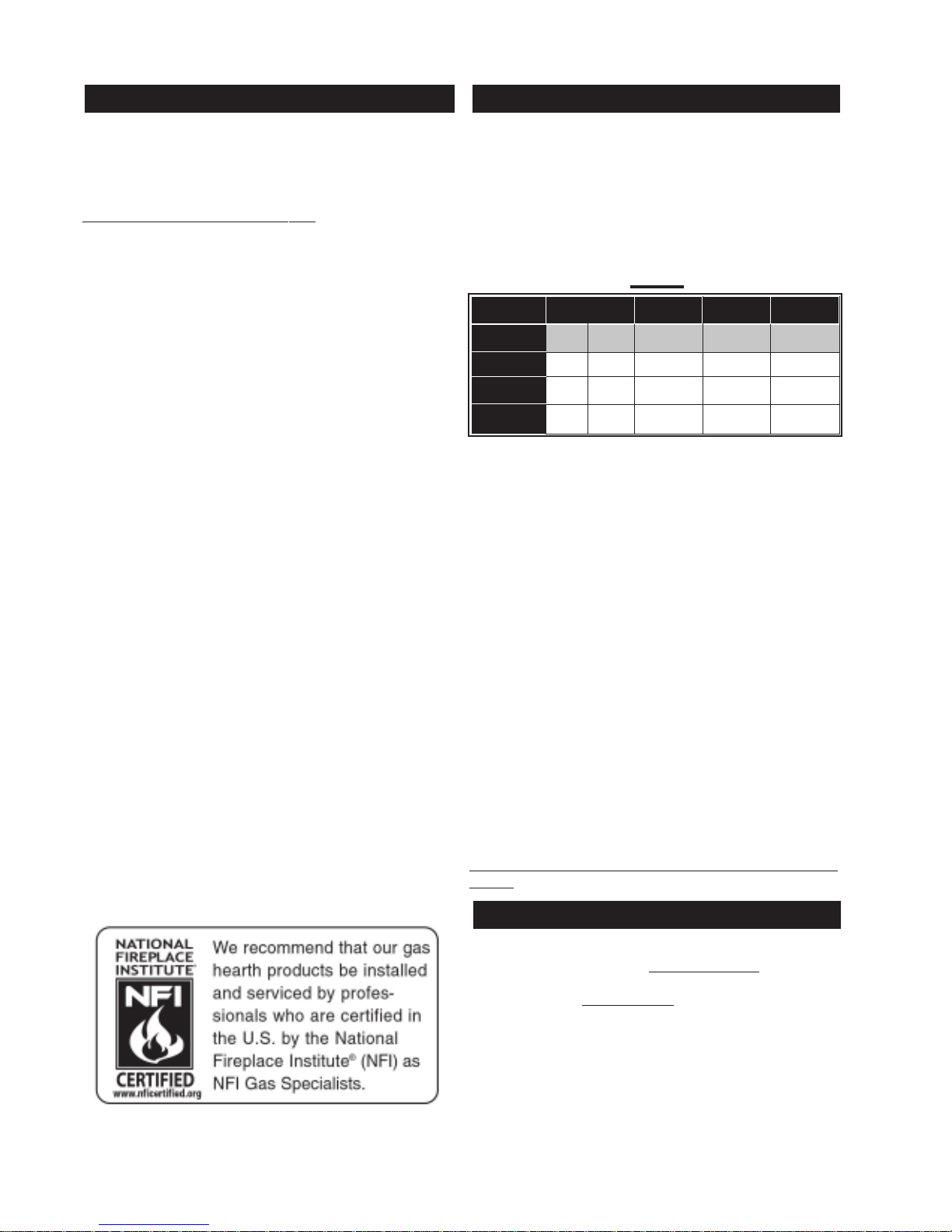
MODEL RA TES AND EFFICIENCIES
MODEL *GD33 BGD33 GD34 BGD34
ALTITUDE
MAX. INPUT
BTU/HR
MAX. OUTPUT
BTU/HR
EFFICIENCY
W/ THE FAN ON
0-2000 2000-4500 0-4500 0-4500 0-4500
FT
22,000 20,000 16,400 24,500 19,000
17,380 15,800 11,644 20,090 14,820
79% 79% 71% 82% 78%
*For elevations between 2,000 and 4,500 ft. above sea
level, this fire place must be de-rated by 10% using the
certified High Altitude Kit.
This fireplace is approved for bathroom, bedroom and
bed-sitting room installations and is suitable for mobile
home installation.
No external electricity (1 10 volts or 24 volts) is required
for the gas system operation.
Expansion / contraction noises during heating up and
cooling down cycles are normal and are to be expected.
Provide adequate circulation air. Provide adequate accessibility clearance for servicing and operating the fireplace. Never obstruct the front opening of the fireplace.
Purge all gas lines with the glass door of the fireplace
removed. Assure that a continuous gas flow is at the
burner before installing the door.
Under extreme vent configurations, allow several
minutes (5-15) for the flame to stablize after ignition.
Six inches is the minimum bend radius allowed for the 7"
diameter flexible liner.
Objects placed in front of the fireplace must be kept at a
minimum of 48" from the front face of the unit.
Use only accessories designed for and listed with the
model.
T ABLE 1
W415-0341 / K / 10.05.07
CARE OF GLASS, AND PLATED PARTS
Do not use abrasive cleaners to clean plated parts. Buff
lightly with a clean dry cloth. BGD33 / BGD34: The glass is
3
/16" tempered glass available from your Napoleon® / Wolf
Steel Ltd. dealer. GD33 / GD34: The glass is 3/16" ceramic
glass available from your Napoleon® / Wolf Steel Lt d. dealer.
DO NOT SUBSTITUTE MATERIALS. Clean the glass after
the first 10 hours of operation with a recommended gas
fireplace glass cleaner. Thereafter clean as required. DO
NOT CLEAN GLASS WHEN HOT! If the glass is not kept
clean permanent discolouration and / or blemishes may
result.
Page 5
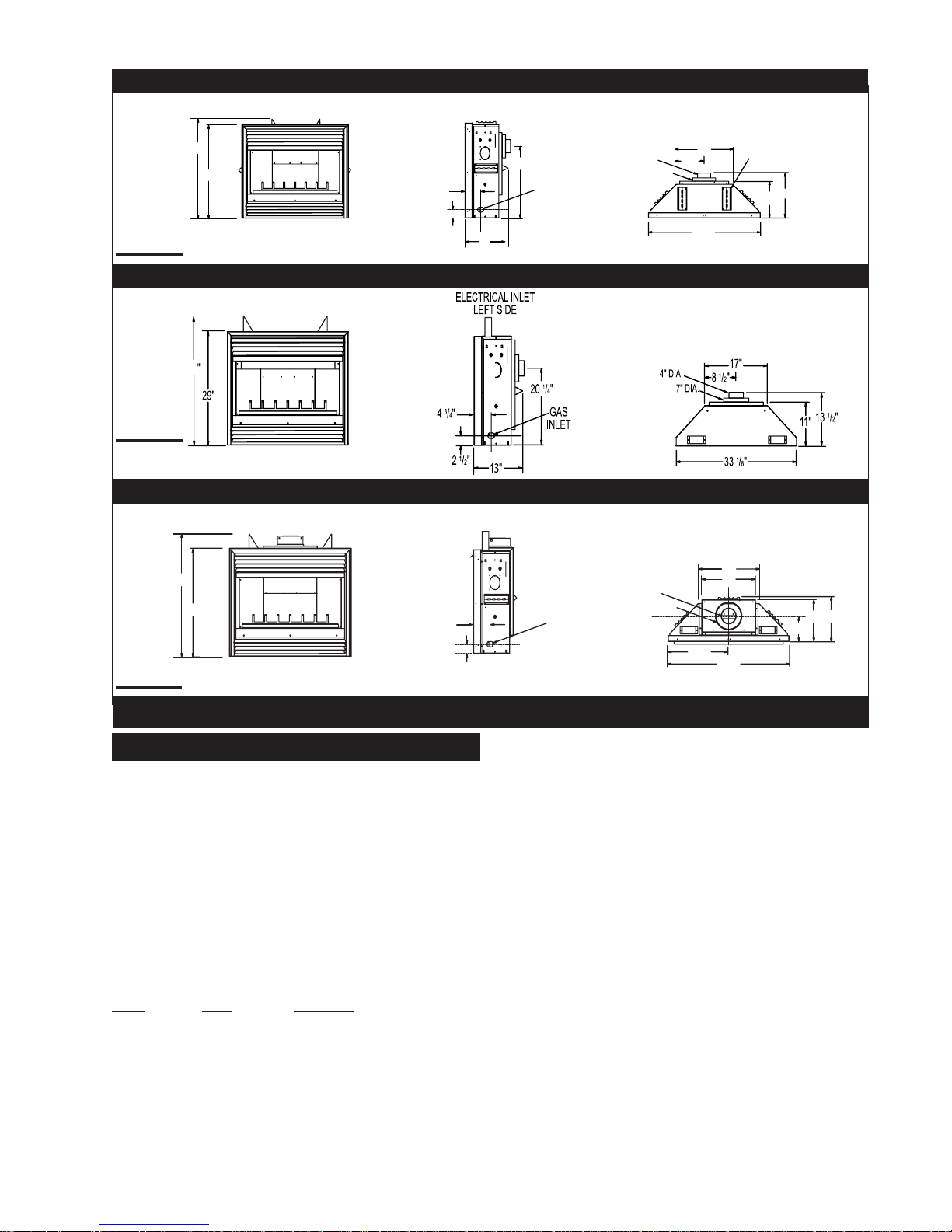
GD33NR
ELECTRICAL INLET
LEFT SIDE
5
FIGURE 1a
FIGURE 1b
33 1/8"
FIGURE 1c
33
29
35"
17"
1
/4"
6” STAND OFF
1
/2"
13
11"
29
7" DIA.
1
/2"
8
34
4" DIA.
13"
20 1/4"
GAS
INLET
5
/8"
3
5
/4"
2 5/8"
BGD33NR
B/GD34NT
ELECTRICAL INLET
LEFT SIDE
17"
17
15"
11"
13"
6 3/4"
1
/8"
1
34
/4"
5
/8"
3
/4"
5
2 5/8"
GAS
INLET
4" DIA.
7" DIA.
VENTING LENGTHS AND AIR TERMINAL LOCATIONS
Use only Wolf Steel, Simpson Dura-Vent, Selkirk Direct
Temp or American Metal Amerivent venting components.
Minimum and maximum vent lengths, for both horizontal
and vertical installations, and air terminal locations for
either system are set out in this manual and must be
adhered to. For Simpson Dura-Vent, Selkirk Direct Temp
and American Metal Amerivent, follow the installation
procedure provided with the venting components.
All outer pipe joints of these venting systems must be
sealed using Red RTV High Temperature Sealant.
A starter adaptor must be used with the following vent
systems and may be purchased from the corresponding
supplier:
PART 4"/7" SUPPLIER
Duravent W175-0053 Wolf Steel
Amerivent 4DSC-N2 American Metal
Direct T emp 4DT-AAN Selkirk
For vent systems that provide seals on the inner exhaust
flue, only the outer air intake joints must be sealed using
a red high temperature silicone (RTV). This same
sealant may be used on both the inner exhaust and the
outer intake vent pipe joints of all other approved vent
systems except for the exhaust vent pipe connection to
the fireplace flue collar which must be sealed using the
black high temperature sealant Mill Pac.
VENTING
When using Wolf Steel venting components, use only
approved Wolf Steel rigid / flexible components with the
following termination kits:Wall Terminal Kit GD222, or 1/12
to 7/12 Pitch Roof Terminal Kit GD110, 8/12 to 12/12 Roof
Terminal Kit GD111, Flat Roof Terminal Kit GD112 or
Periscope Kit GD201 (for wall penetration below grade).
With flexible venting, in conjunction with the various
terminations, use either the 5 foot Vent Kit GD220 or the 10
foot Vent Kit GD330.
The maximum allowable vertical vent length is 40 feet.
For optimum flame appearance and fireplace performance,
keep the vent length and number of elbows to a minimum.
The air terminal must remain unobstructed at all times.
Examine the air terminal at least once a year to verify that it
is unobstructed and undamaged.
Horizontal runs may have a 0 inch rise per foot in all
cases using Wolf Steel, Simpson Dura-Vent, Selkirk
Direct Temp, or American Metal Amerivent rigid vent
components and Wolf Steel flexible vent components.
For optimum performance, it is recommended that
horizontal runs have a minimum 1/4 inch rise per foot
when using Simpson Dura-Vent, Selkirk Direct Temp,
American Metal Amerivent or Wolf Steel rigid vent
components and a minimum 1 inch rise per foot when
using Wolf Steel flexible vent comonents. For safe and
proper operation of the fireplace,
follow the venting instructions exactly.
W415-0341 / K / 10.05.07
Page 6
6
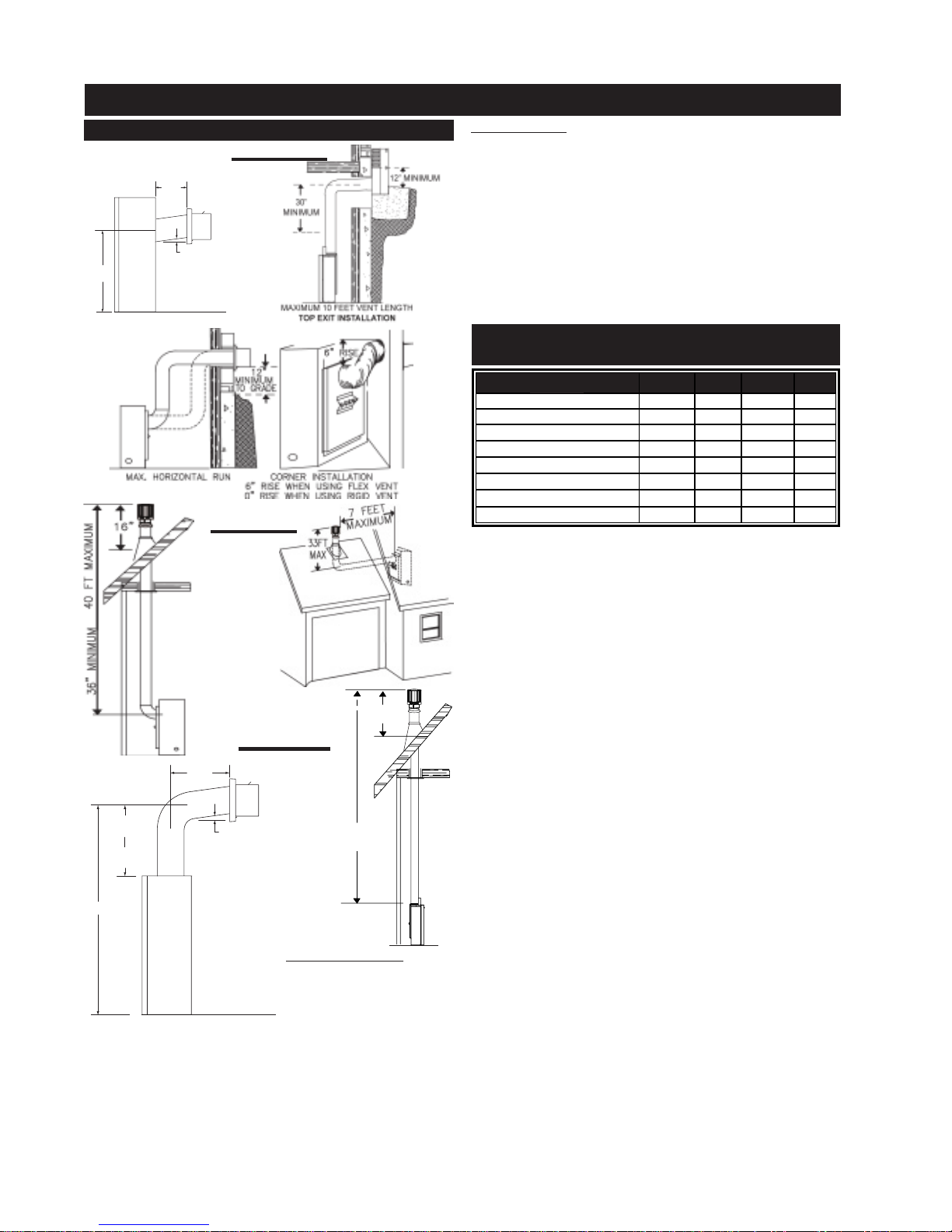
TYPICAL VENT INSTALLATIONS
24" MAXIMUM
8" MINIMUM (BGD33)
12" MINIMUM (GD33)
1" RISE / FT *
20 1/4"
* REFER TO "VENTING SECTION"
VENT INSTALLATIONS
FIGURES 2a - d
ALL MODELS: Vent lengths that pass through unheated
spaces (attics, garages, crawl spaces) should be insulated with the insulation wrapped in a protective sleeve
to minimize condensation.
Provide a means for visually checking the vent connection to the fireplace after the fireplace is installed.
Do not allow the inside liner to bunch up on horizontal or
vertical runs and elbows. Keep it pulled tight. A 1¼" air
gap between the inner and outer liner all around is required for safe operation.
Use a firestop, vent pipe shield or attic insulation shield
when penetrating interior walls, floor or ceiling.
Minimum clearance to combustible construction
from fireplace and vent surfaces:
FIGURE 3a - b
16”
MINIMUM
F I G U R E 4 a - b
24” MAX
11” MIN
10” MINIMUM
24” MINIMUM
53 5/8”
(BGD34)
(GD34)
1” RISE/FT*
40 FT MAXIMUM
3 FT MINIMUM
BGD33 and GD33: When
venting straight out the
back, only the rigid vent
can be used. Do not use
* REFER TO “VENTING SECTION”
flexible vent. For all other
venting configurations, flexible vent is acceptable. When
venting either a GD33 or a BGD33, the horizontal run
must be kept to a maximum of 24 inches. A GD33 must
be kept to a minimum of 12 inches and a BGD33 must be
kept to a minimum of 8 inches. When terminating vertically, the vertical rise is a minimum 36 inches to a maximum 40 feet from the centre of the fireplace flue outlet.
W415-0341 / K / 10.05.07
TABLE 2
SIDE OF THE UNIT 0" 0" 0" 0"
BACK OF THE UNIT 0" 0" 0" 0"
BOTTOM OF THE UNIT 0" 0" 0" 0"
TOP OF THE UNIT 0" 0" 0" 51/8"**
TOP OF THE VENT PIPE 2"* 2"* 2" 2"
SIDES OF THE VENT PIPE 1" 1" 1" 1"
BOTTOM OF THE VENT PIPE 1" 1" 1" 1"
RECESSED DEPTH 13" 13" 13" 13"
BGD33 GD33 BGD34 GD34
* A clearance to combustibles of 2" at the vent pipe top
must be maintained. The firestop spacer W010-1777sup-
plied with the unit must be used to maintain this clearance.
** The first 5 1/8" of finishing material above the GD34
must be non-combustible. The header must be steel.
For safe and proper operation of the fireplace follow the
venting instruction exactly.
Deviation from the minimum or the maximum vertical
vent length can create difficulty in burner start-up and/
or carboning.
A terminal shall not terminate directly above a sidewalk
or paved driveway which is located betweeen two single family dwellings and serves both dwellings. Local
codes or regulations may require different clearances.
In order to avoid the possibility of exposed insulation or
vapour barrier coming in contact with the fireplace
body, it is recommended that the walls of the fireplace
enclosure be “finished” (ie: drywall/sheetrock), as you
would finish any other outside wall of a home. This will
ensure that clearance to combustibles is maintained
within the cavity.
Wolf Steel, Simpson Dura-Vent, Selkirk Direct Temp and
American Metal Amerivent venting systems must not be
combined.
Purge all gas lines with the glass door of the fireplace
open. Assure that a continuous gas flow is at the burner
before closing the door.
Under extreme vent configurations, allow several minutes
(5-15) for the flame to stabilize after ignition.
Six (6") inches is the minimum bend radius allowed for
the 7" diameter flexible liner.
FOR SPECIFIC VENTING PARAMETERS, REFER T O
PAGES 9-14.
Page 7
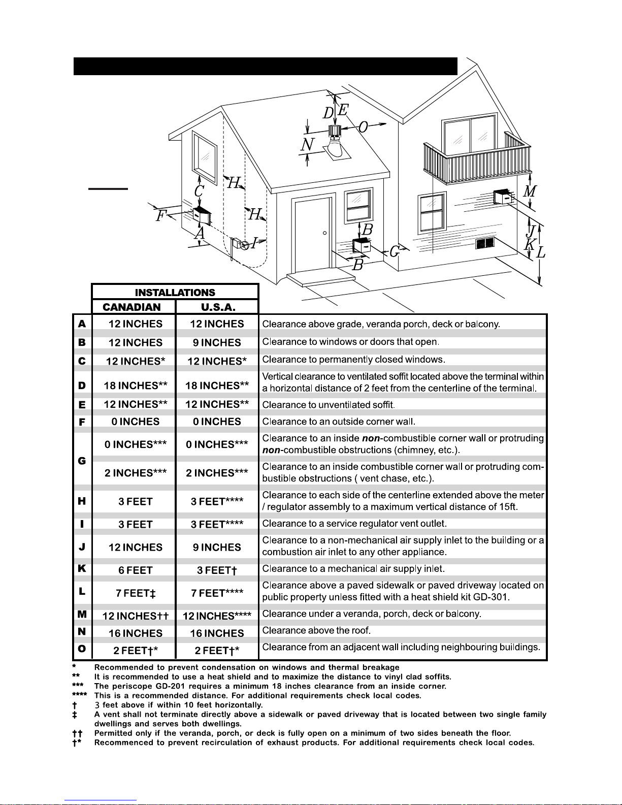
MINIMUM AIR TERMINAL LOCATION CLEARANCES
FIGURE 5
7
W415-0341 / K / 10.05.07
Page 8
8
l
l
tiontion
tiontion
tion
minamina
minamina
mina
erer
erer
er
TT
TT
T
tical tical
tical tical
tical
erer
erer
er
VV
VV
V
than
Vertical
rise is less
or greater
is equal to
Vertical rise
run
horizontal
run
than the
horizontal
run +
rise to
vertical
Horizontal
run +
rise to
vertical
Horizontal
of 40 feet
maximum
of 40 feet
maximum
3 times the
greater
equal to or
vertical rise
run
than the
horizontal
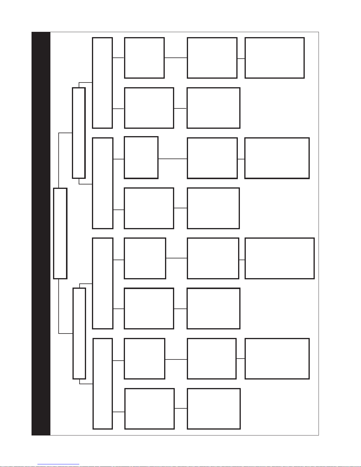
BGD34 & GD34BGD34 & GD34
BGD34 & GD34BGD34 & GD34
BGD34 & GD34
ent Exitent Exit
ent Exitent Exit
ent Exit
VV
VV
V
place place
place place
place
ee
ee
e
FirFir
FirFir
Fir
tiontion
tiontion
tion
minamina
minamina
mina
erer
erer
er
HorizontalHorizontal
HorizontalHorizontal
Horizontal
TT
TT
T
tiontion
tiontion
tion
minamina
minamina
mina
erer
erer
er
TT
TT
T
tical tical
tical tical
tical
erer
erer
er
VV
VV
V
Vertical rise
Vertical rise
Vertical
Vertical rise
run
horizontal
is less than
than the
or greater
is equal to
rise is less
is equal to
horizontal
run
than
horizontal
than the
or greater
horizontal
run
run
run +
Horizontal
Horizontal
Horizontal
Horizontal
to maxi-
vertical rise
run +
vertical
run +
vertical
run +
rise to
vertical
mum of
24.75 feet
rise to
of 40 feet
maximum
rise to
of 40 feet
maximum
of 40 feet
maximum
4.2 times
rise equal
the vertica
equal to or
3 times the
vertical rise
to or
greater
greater
run
than the
horizontal
run
than the
horizontal
VENTING APPLICATION FLOW CHART
BGD33 & GD33BGD33 & GD33
BGD33 & GD33BGD33 & GD33
BGD33 & GD33
tiontion
tiontion
tion
minamina
minamina
mina
erer
erer
er
HorizontalHorizontal
HorizontalHorizontal
Horizontal
TT
TT
T
W415-0341 / K / 10.05.07
than
Vertical
rise is less
or greater
is equal to
Vertical rise
run
horizontal
run
than the
horizontal
run +
Horizontal
Horizontal
to maxi-
vertical rise
run +
rise to
vertical
mum of
24.75 feet
of 40 feet
maximum
3.5 times
rise equal
the vertica
to or
greater
run
than the
horizontal
Page 9
9
DEFINITIONS
for the following symbols used in the venting calculations and examples are:
> - greater than
> - equal to or greater than
< - less than
< - equal to or less than
H
- total of both horizontal vent lengths (HR) and offsets
T
(HO) in feet
H
- combined horizontal vent lengths in feet
R
H
- offset factor: .03(total degrees of offset - 90°
O
feet
V
- combined vertical vent lengths in feet
T
**
*) in
**
ELBOW VENT LENGTH VALUES
feet inches
1° 0.03 0.5
15° 0.45 6.0
30° 0.9 11.0
45° 1.35 16.0
**
90°
* 2.7 32.0
**
* *
* the first 90° offset has a zero value and is shown in
* *
the formula as -90°
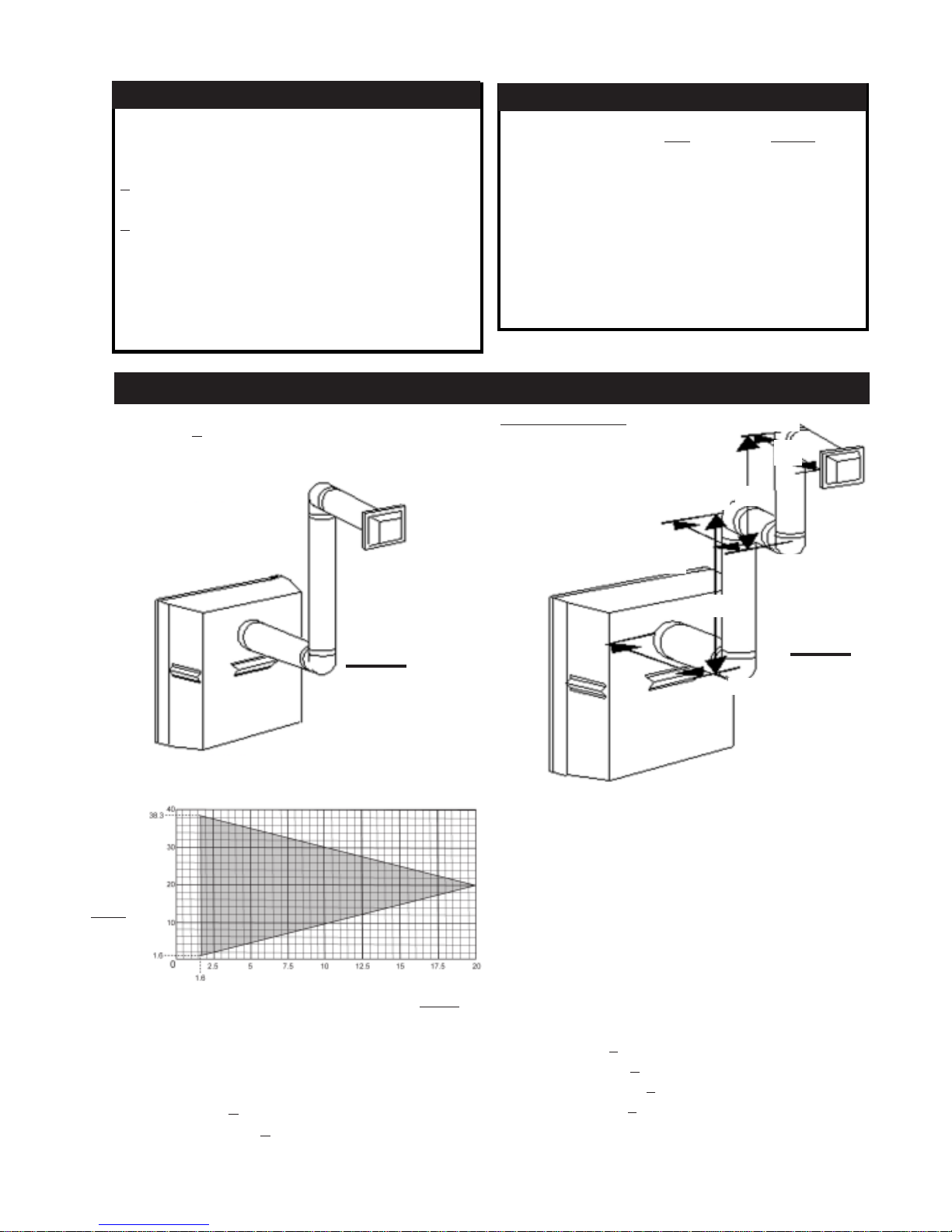
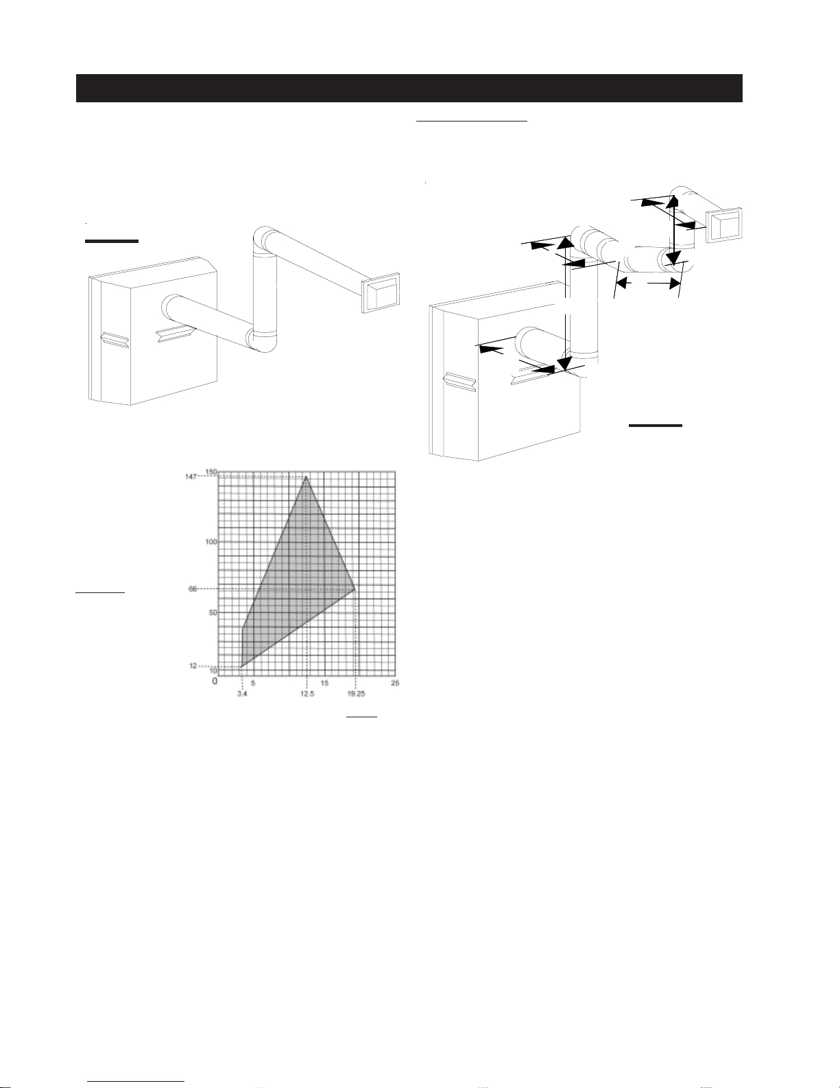
BGD33 & GD33 HORIZONTAL TERMINATION
Example 1:Example 1:
Example 1:
(H(H
) )
<<
(V (V
when
(H
(H(H
)
) )
TT
T
TT
<
<<
(V
(V (V
))
)
))
TT
T
TT
Simple venting configuration (only two 90° elbows)
Example 1:Example 1:
H
2
90°
V
90°
2
H
3
90°
FIGURE 6
See graph to determine the required vertical rise VT for the
required horizontal run H
T
REQUIRED
VERTICAL
RISE IN
FEET
V
T
HORIZONTAL VENT RUN PLUS OFFSETS IN FEET
The shaded area within the lines represents acceptable
values for HT and V
.
T
For vent configurations requiring more than two 90° elbows the following formulas apply:
Formula 1: HT < V
T
Formula 2: HT + VT < 40 feet
V
1
H
1
V
1
V
2
V
T
H
1
H
2
H
3
H
R
H
O
=9 f t
=6 f t
=
V1 +
V2 =
9 + 6 = 15 ft
=3 f t
=2 f t
=1.5 ft
=H1 + H2 + H3 = 3 + 2 + 1.5 = 6.5 ft
=.03(four 90° elbows - 90°)
=.03(90 + 90 + 90 + 90 - 90) = 8.1 ft
H
HH
H
HH
T
TT
T
TT
HT + VT=14.6 + 15 = 29.6 ft
Formula 1: HT < V
=HR + HO = 6.5 + 8.1 = 14.6 ft
T
14.6 < 15
Formula 2: HT + VT < 40 feet
29.6 < 40
Since both formulas are met, this vent configuration is acceptable.
FIGURE 7
90°
W415-0341 / K / 10.05.07
Page 10
10
BGD33 & GD33 HORIZONTAL TERMINATION
(H(H
(H
(H(H
) > (V) > (V
) > (V
) > (V) > (V
TT
T
TT
when
Simple venting configuration (only two 90° elbows)
FIGURE 8
See graph to determine the required vertical rise VT for the
required horizontal run H
))
)
))
TT
T
TT
T
Example 2:Example 2:
Example 2:
Example 2:Example 2:
H
90°
H
90°
90°
45°
H
FIGURE 9
3
H
2
V
1
1
V
4
2
90°
REQUIRED
VERTICAL
RISE IN
INCHES
V
T
HORIZONTAL VENT RUN PLUS OFFSETS IN
FEET
HH
H
HH
The shaded area within the lines represents acceptable
values for HT and V
.
T
For vent configurations requiring more than two 90° elbows
the following formulas apply:
Formula 1: HT < 3.5V
T
Formula 2: HT + VT < 24.75 feet
V
1
V
2
V
T
H
1
H
2
H
3
H
4
H
R
H
O
=4 f t
=1.5 ft
=
V1 +
V2 =
4 + 1.5 = 5.5 ft
=2 f t
=1 f t
=1 f t
=1.5 ft
=H1 + H2 + H3 + H4 = 2 + 1 + 1 + 1.5 = 5.5 ft
=.03(four 90° elbows + one 45° elbow - 90°)
=.03(90 + 90 + 90 + 90 + 45 - 90) = 9.45 ft
H
T
=HR + HO = 5.5 + 9.45 = 14.95 ft
HT + VT= 14.95 + 5.5 = 20.45 ft
Formula 1: HT < 3.5V
TT
T
TT
14.95 < 19.25
T
3.5VT =
3.5 x
5.5 = 19.25 ft
Formula 2: HT + VT < 24.75 feet
20.45 < 24.75
Since both formulas are met, this vent configuration is acceptable.
W415-0341 / K / 10.05.07
Page 11
BGD34 & GD34 HORIZONTAL TERMINATION
11
when (H
) < (VT)
T
Simple venting configuration (only one 90° elbow)
FIGURE 10
See graph to determine the required vertical rise VT for the
required horizontal run HT.
VERTICAL
RISE IN
FEET
V
T
HORIZONTAL VENT RUN PLUS OFFSET IN FEET
The shaded area within the lines represents acceptable
values for HT and V
.
T
For vent configurations requiring more than one 90° elbow, the following formulas apply:
Formula 1: HT < V
T
Formula 2: HT + VT < 40 feet
90°
FIGURE 11
90°
V
Example 3:
V
=3 ft
1
V
=8 ft
2
V
=
V
+
V
=
3 + 8 = 1 1 ft
2
< V
T
T
9.9 < 1 1
+ VT < 40 feet
T
20.9 < 40
H
HH
HH
TT
T
TT
T
H
1
H
2
H
R
H
O
H
T
HT + V
1
= 2.5 ft
=2 ft
= H1 + H2 = 2.5 + 2 = 4.5 ft
=.
03(three 90° elbows - 90°) = .03(270° - 90°) = 5.4 ft
= HR + HO = 4.5 + 5.4 = 9.9 ft
= 9.9 + 11 = 20.9 f t
T
Formula 1: H
Formula 2: H
Since both formulas are met, this vent configuration is acceptable.
1
V
2
H
90°
1
H
2
W415-0341 / K / 10.05.07
Page 12

12
BGD34 & GD34 HORIZONTAL TERMINATION
when (HT) > (V
Simple venting configura-
tion
(only one 90° elbow)
FIGURE 12
See graph to determine the required vertical rise V
quired horizontal run HT.
)
T
for the re-
T
Example 5:
V
90°
2
H
H
4
3
H
1
H
V
2
90°
1
FIGURE 14
REQUIRED
VERTICAL
RISE IN
INCHES
V
T
HORIZONTAL VENT RUN PLUS OFFSET IN FEET
H
HH
HH
The shaded area within the lines represents acceptable
values for HT and V
.
T
For vent configurations requiring more than one 90° elbow
the following formulas apply:
Formula 1: HT < 4.2 V
T
Formula 2: HT + VT < 24.75 feet
H
V
1
1
90°
FIGURE 13
H
2
V
1
V
2
V
T
H
1
H
2
H
3
H
4
H
R
H
O
H
T
TT
T
TT
HT + V
Formula 1:H
Formula 2:H
=4 ft
= 1.5 ft
= V1 + V2 = 4 + 1.5 = 5.5 ft
=2 ft
=1 ft
=1 ft
= 1.5 ft
= H1 + H2 + H3 + H4 = 2 + 1 + 1 + 1. 5 = 5.5 ft
= .03(four 90° elbows - 90°) = .03(360° - 90°) = 8.1 ft
= HR + HO = 5.5 + 8.1 = 13.6 ft
= 13.6 + 5.5 = 19.1 ft
T
< 4.2 V
T
13.6 < 23.1
+ VT < 24.75 feet
T
4.2 V
T
= 4.2 x 5.5 = 23.1 ft
T
19.1 < 24.75
Since both formulas are met, this vent configuration is acceptable.
Example 4:
V
H
H
H
H
H
HT + V
Formula 1: H
Formula 2: H
= VT = 6 ft
1
=3 ft
1
=5 ft
2
= H1 + H2 = 3 + 5 = 8 ft
R
= .03(two 90° elbows - 90°) = .03(180° - 90°) = 2.7 ft
O
= HR + HO = 8 + 2.7 = 10.7 ft
T
=
10.7 + 6 =16.7
T
< 4.2 V
T
10.7 < 25.2
+ VT < 24.75 feet
T
4.2 V
T
= 4.2 x 6 = 25.2 ft
T
16.7 < 24.75
Since both formulas are met, this vent configuration is acceptable.
W415-0341 / K / 10.05.07
Page 13

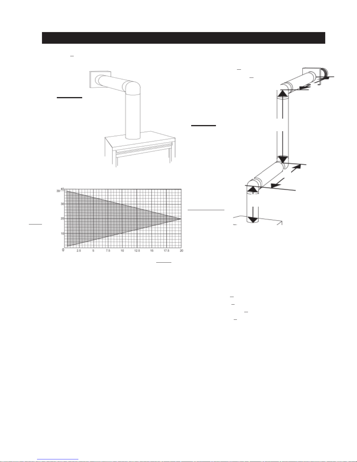
VERTICAL TERMINATION
13
when (H
) < (VT)
T
Simple venting configurations
FIGURE 15
BGD34 / GD34
BGD33 / GD33
See graph to determine the required vertical rise VT for the
required horizontal run HT.
REQUIRED
VERTICAL RISE
IN FEET
V
T
HORIZONTAL VENT RUN PLUS OFFSET IN FEET
H H
H
H H
The shaded area within the lines represents acceptable
values for HT and V
.
T
For vent configurations requiring more than zero 90° elbow
(top exit) or one 90° elbow (rear exit), the following formulas apply:
Formula 1: HT < V
T
Formula 2: HT + VT < 40 feet
Example 6:
FIGURE 16
90°
V
H
1
V
1
V
2
V
T
H
1
H
2
H
R
H
O
H
T
HT + V
Formula 1: H
Formula 2: H
TT
T
TT
Since both formulas are met, this vent configuration is acceptable.
=5 f t
=10 ft
=
V
+
V
=
1
5 + 10 = 15 ft
2
=3 f t
=2.5 ft
=H1 + H2 = 3 + 2.5 = 5.5 ft
=.03(three 90° elbows - 90°)
=.03(90 + 90 + 90 - 90) = 5.4 ft
=HR + HO = 5.5 + 5.4 = 10.9 ft
= 10.9 + 15 = 25.9 ft
T
< V
T
10.9 < 1 5
T
+ VT < 40 feet
T
25.9 < 40
H
1
90°
V
2
2
90°
W415-0341 / K / 10.05.07
Page 14

14
VERTICAL TERMINATION
when (H
) > (VT)
T
Simple venting configurations
FIGURE 17
BGD34 / GD34
BGD33 / GD33
See graph to determine the required vertical rise VT for the
required horizontal run HT.
MAXIMUM
VERTICAL
RISE IN
FEET
V
T
HORIZONTAL VENT RUN PLUS OFFSET IN FEET
The shaded area within the lines represents acceptable
values for HT and V
.
T
For vent configurations requiring more than two 90° elbow
(top exit) or one 90° elbow (rear exit), the following formulas apply:
Formula 1: HT < 3V
T
Formula 2: HT + VT < 40 feet
Example 7:
90°
90°
V
V
1
H
1
V
H
2
2
90°
FIGURE 18
W415-0341 / K / 10.05.07
HH
H
HH
3
90°
V
1
V
2
V
3
V
T
H
1
H
2
H
R
H
O
=2 f t
=1 f t
=1.5 ft
=
V
+
V
+
V
=
1
2
2 + 1 + 1.5 = 4.5 ft
3
=6 f t
=2 f t
=H1 + H2 = 6 + 2 = 8 ft
=.03(four 90° elbows - 90°)
=.03(90 + 90 + 90 + 90 - 90) = 8.1 ft
H
T
HT + V
Formula 1: H
=HR + HO = 8 + 8.1 = 16.1 ft
= 16.1 + 4.5 = 20.6 ft
T
< 3V
T
16.1 > 13.5
3V
T
=
3 x
T
4.5 = 13.5 ft
Since this formula is not met, this vent configuration is unac-
ceptable.
Formula 2: H
+ VT < 40 feet
T
< 40
20.6
Since only formula 2 is met, this vent configuration is unacceptable and a new fireplace location or vent configuration
will need to be established to satisfy both formulas.
Example 8:
TT
T
TT
V
1
V
2
V
T
H
1
H
2
H
3
H
R
H
O
H
T
HT + V
Formula 1: H
Formula 2: H
Since both formulas are met, this vent configuration is acceptable.
90°
H
2
45°
V
H
1
1
90°
H
3
FIGURE 19
=1.5 ft
=5 f t
=
V
+
V
=
1
1.5 + 5 = 6.5 ft
2
=1 f t
=1 f t
=10.75 ft
=H1 + H2 + H3 = 1 + 1 + 10.75 = 12.75 ft
=.03(three 90° elbows + one 45° elbow - 90°)
=.03(90 + 90 + 90 + 45 - 90) = 6.75 ft
=HR + HO = 12.75 + 6.75 = 19.5 ft
= 19.5 + 6.5 = 26 ft
T
< 3V
T
19.5 = 19.5
T
T
3V
=
3 x
6.5 = 19.5 ft
T
+ VT < 40 feet
26 < 40
V
2
90°
Page 15
d
p
l
l
l
l
l
A
A
A
g
N
H
to
c
nt
a
g
c
th
t
V
to
c
d.
INSTALLATION
This application occurs when venting through an exterior
w
a
y
1
a
N
I
1
k
t
s
r
2
e
s
to
t
is
i
3
n,
a
n
t
N
E/
L
F
M
1. Assemble the two halves of the vent sleeve by aligning
t
e
(
d
i
N
S.
S
2
s
o
a
t
o
a
r
s
F
WALL AND CEILING PROTECTION
For optimum performance, it is recommende
that horizontal runs have a minimum ¼ inch rise
er foot when using
SelkirSelkir
Selkir
SelkirSelkir
Amerivent, or
Amerivent, or
and a minimum 1 inch rise per foot when usin
Wolf Steel flexible vent components
he unit must be used to maintain the clearance.
k Dirk Dir
k Dir
k Dirk Dir
merivent, or
merivent, or Wolf Steel rigid vent components
merivent, or
For safe and proper operation of the fireplace,
follow the venting instructions exactly.
OTE:
ORIZONTAL TERMINATION - A clearance
ombustibles of 1" at the bottom and sides of the ve
nd 2" at the top must be maintained when penetratin
ombustible walls. The firestop spacer supplied wi
ERTICAL TERMINATION - Only a clearance
ombustibles of 1" all around the vent pipe is require
ect ect
ect
ect ect
Simpson DurSimpson Dur
Simpson Dur
Simpson DurSimpson Dur
TT
empemp
,,
emp
empemp
,
,,
T
TT
American Meta
American Meta
American Meta
American Meta
American Meta
a-Va-V
a-V
a-Va-V
ent,ent,
ent,
ent,ent,
15
all. Having determined the air terminal location, cut
nd frame a hole in the exterior wall 9 7/8 inches wide b
1 3/8 inches high to accommodate the firestop sleeve
ssembly.
OTE: THE FIRESTOP SLEEVE ASSEMBLY MUST BE
NSTALLED WITH THE 2" CLEARANCE T O THE TOP.
. Insert the firestop sleeve assembly into the wall, mar
he wall depth and trim the vent sleeve to suit. The
crews that secure the vent sleeve may need to be
epositioned to ensure a rigid assembly is maintained.
. Apply a bead of caulking (not supplied) to the insid
urface of the firestop flange and secure the assembly
he wall. (Ensure that the rectangular shaped assembly
nstalled to maintain 2" from the top of the vent).
. Once the vent pipe liner is installed in it's final positio
pply high temperature sealant (not supplied) betwee
he pipe/liner, and the firestop.
GD33/BGD33 HORIZONTAL INSTALLATION
FIRESTOP SLEEVE ASSEMBLY
he holes that come together to make a rectangular shap
lip to the outside). Secure using 6 of the screws supplie
n the manual baggie.
OTE: SCREWS NOT REQUIRED IN TWO BLIND HOLE
ee Figure 20a.
. Fit the firestop
pacer into one end
f the vent sleeve
nd secure through
he aligned holes
n the top, bottom,
nd sides with the
emaining 5 screws
upplied. See
igure 20b.
If flexible venting is to be used remove the rigid firestop
spacer. The remaining hole is sized for flexible venting.
FIGURE 20b
OTE: DO NOT FILL THE CA VITY BETWEEN THE PIP
INER AND THE VENT SLEEVE WITH ANY TYPE O
ATERIAL.
FIGURE 21
FIGURE 20a
W415-0341 / K / 10.05.07
Page 16

16
A
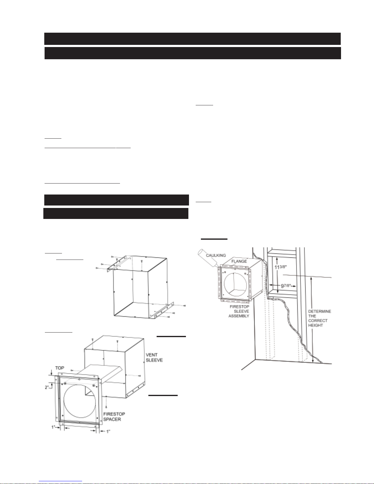
GD34/BGD34 HORIZONTAL INSTALLATION
This application occurs when venting through an exterior
wall. Having determined the correct height for the air terminal
location, cut and frame a hole in the exterior wall 9 7/8 inches
wide by 11 3/8 inches high to accomodate the firestop
assembly. Dry fit the firestop assembly before proceeding
to ensure the brackets on the rear surface fit to the inside
surface of the horizontal framing.
As an alternative to framing, the vent pipe/liner can be
enclosed in the wall using Napoleon® vent sleeve VS47KT.
NOTE: THE FIRESTOP ASSEMBL Y MUST BE INST ALLED
WITH THE VENT SHIELD TO THE TOP.
1. Apply a bead of caulking (not supplied) around the corner
edge of the inside surface of the firestop assembly, fit the
firestop assembly to the hole and secure using the 4 screws
(W415-0026) supplied in your manual baggie.
2. Once the vent pipe / liner is installed in its final position,
apply high temperature sealant (not supplied) between the
pipe/liner and the firestop.
NOTE: DO NOT FILL THE CAVITY BETWEEN THE PIPE/
LINER AND THE FRAMING WITH ANY TYPE OF
MATERIAL.
FIGURE 22
VENT
SHIELD
ULKING
3/8
11
”
FIRESTOP
SSEMBLY
7/8
9
”
FINISHING
MATERIAL
DETERMINE
THE
CORRECT
HEIGHT
VERTICAL INSTALLATION
This application occurs
when venting through a
roof. Installation kits for
various roof pitches are
available from your
Napoleon dealer. See
Accessories to order
the specific kit required.
FIGURE 23
1. Determine the air terminal location, cut and frame 9½
inch openings in the ceiling and the roof to provide the
minimum clearance between the fireplace pipe / liner and
any combustible material. Try to center the exhaust pipe
location midway between two joists to prevent having to
cut them. Use a plumb bob to line up the center of the
openings.
Do not fill this space with any type of material.
A vent pipe shield will
prevent any materials
such as insulation,
from filling up the 1" air
space around the pipe.
Nail headers between
the joist for extra support.
2. Apply a bead of
caulking (not supplied)
to the framework or to the Wolf Steel vent pipe shield plate
or equivalent (in the case of a finished ceiling), and secure
over the opening in the ceiling. A firestop must be placed
on the bottom of each framed opening in a roof or ceiling
that the venting system passes through. Apply a bead of
caulking all around and place a firestop spacer over the
vent shield to restrict cold air from being drawn into the
room or around the fireplace. Ensure that both spacer and
shield maintain the required clearance to combustibles.
Once the vent pipe / liner is installed in its final position,
apply sealant between the pipe / liner and the firestop
spacer.
3. In the attic, after the pipe / liner has been installed,
slide the vent pipe collar down to cover up the open end of
the shield and tighten. This will prevent any materials, such
as insulation, from filling up the 1" air space around the
pipe.
FIGURE 24
W415-0341 / K / 10.05.07
FIGURE 25
Page 17

USING FLEXIBLE VENT COMPONENTS
Use only approved aluminum flexible liner kits marked:
"Wolf Steel Approved Venting" as
identified by the stamp only on the 7”
outer liner.
HORIZONTAL AIR TERMINAL INSTALLATION
For safe and proper operation of the fireplace, follow
the venting instructions exactly.
1. Cut or frame a hole in an exterior wall with a minimum
round or square opening listed in TABLE 2 on page 6.
Secure the firestop spacer over the opening to the interior
wall.
2. Stretch the 4" diameter aluminum flexible liner to the
required length taking into account the additional length
needed for the finished wall surface. Slip the liner a minimum of 2" over the inner sleeve of the air terminal and
secure with 3 #8 screws. Apply a heavy bead of the high
temperature sealant.
3. Using the 7" diameter flexible aluminum liner, slide
over the outer combustion air sleeve of the air terminal and
secure with 3 #8 screws. Seal as before.
FIGURE 26
GD33 and BGD33: When venting straight out the back, only
the rigid vent can be used. Do not use flexible vent. For all
other venting configurations, flexible vent is acceptable.
For optimum performance, it is recommended that
horizontal runs have a minimum ¼ inch rise per foot
when using Simpson Dura-Vent, Selkirk Direct Temp,
American Metal Amerivent, or Wolf Steel rigid vent components and a minimum 1 inch rise per foot when using
Wolf Steel flexible vent components.
For safe and proper operation of the fireplace, follow the
venting instructions exactly.
4. Insert the liners through the firestop maintaining the
required clearance to combustibles. Holding the air terminal (lettering in an upright, readable position), secure to
the exterior wall and make weather tight by sealing with
caulking (not supplied).
5. Apply a heavy bead of the high temperature sealant,
supplied with the unit, to the inside of the 4" liner approximately 1" from the end. Slip the liner a minimum of 2" over
the fireplace vent collar and secure with 3 #8 screws.
6. Using the 7" diameter flexible aluminium liner, apply
sealant, slide a minimum of 2" over the fireplace combustion air collar and secure with 3 #8 screws.
VERTICAL AIR TERMINAL INSTALLATION
1. Fasten the roof
support to the roof
using the screws
provided. The roof
support is
optional. In this
case the venting
is to be
adequately
supported using
either an alternate
FIGURE 28
method suitable
to the authority
having jurisdiction or the optional roof support. (Fig. 28)
17
The air terminal mounting plate may be recessed into
the exterior wall or siding by 1½", the depth of the return
flange.
FIGURE 27
2. Stretch the inner aluminum
flex liner to the required length.
Slip the liner a minimum of
FIGURE 29
INNER
SLEEVE
2” over the inner sleeve of the
air terminal connector and
secure with 3 #8 screws.
Seal using a heavy bead of
the high temperature
sealant. (Fig. 29)
AIR
TERMINAL
CONNECTOR
3. Repeat using the outer
aluminum flex liner. (Fig. 29)
4. Thread the air terminal
connector / liner assembly
down through the roof. The air
terminal must be located
HIGH
TEMPERATURE
SEALANT
INNER FLEX
LINER
OUTER FLEX
LINER
vertically and plumb. Attach
the air terminal connector to the roof support, ensuring that
the top of the air terminal is 16” above the highest point that
it penetrates the roof. (Fig. 30)
W415-0341 / K / 10.05.07
Page 18

18
5. Remove nails from the shingles, above and to the sides
of the chimney. Place the flashing over the air terminal
connector leaving a min. 3/4” of the air terminal connector
showing above the top of the flashing. Slide the flashing
underneath the sides and upper edge of the shingles.
Ensure that the air terminal connector is properly centred
within the flashing, giving a 3/4” margin all around. Fasten
to the roof. Do not nail through the lower portion of the
flashing. Make weather-tight by sealing with caulking.
Where possible, cover the sides
flashing with roofing material. (Fig. 30)
6. Aligning the seams of the terminal and air terminal
connector, place the terminal over the air terminal
connector making sure the liner goes into the hole in
the terminal. Secure with the three screws provided.
(Fig. 30)
7. Apply a heavy bead of weatherproof caulking 2 inches
above the flashing. Note: Maintain a minimum 2” space
between the air inlet base and the storm collar. Inst all
the storm collar around the air terminal and slide down
to the caulking. Tighten to ensure that a weather-tight
seal between the air terminal and the collar is achieved.
(Fig. 30)
and top edges of the
USING RIGID VENT
COMPONENTS
For optimum performance, it is recommended that
horizontal runs have a minimum ¼ inch rise per foot
when using Simpson Dura-Vent, Selkirk Direct Temp,
American Metal Amerivent, or Wolf Steel rigid vent
components.
For safe and proper operation of the fireplace, follow
the venting instructions exactly.
The vent system must be supported approximately every 3
feet for both vertical and horizontal runs. Use Wolf Steel
vent spacers W615-0033 every 3 feet on either side of
each elbow to maintain the minimum 1¼" clearance
between the outer and inner vent pipes. Use Napoleon®
support ring assembly W010-0370 or equivalent
noncombustible strapping to maintain the minimum
clearance to combustibles for both vertical and horizontal
runs.
FIGURE 31
FIGURE 30
2”
STORM COLLAR
Spacers are attached to the inner flex liner at
predetermined intervals to maintain a 1-1/4” air gap to
the outer flex liner. These spacers must not be removed.
AIR INLE T
BASE
CAULKING
WEATHE R
SEALANT
FLASHING
FIREPLACE VENT CONNECTION
1. Install the 4 inch diameter aluminium flexible liner to
the fireplace. Secure with 3 screws and flat washers. Seal
the joint and screw holes using the high temperature sealant provided.
2. Install the 7 inch diameter aluminium flexible liner to
the fireplace. Attach and seal the joints.
HORIZONTAL AIR TERMINAL INSTALLATION
1. Move the fireplace into position. Measure the vent length
required between terminal and fireplace taking into account
the additional length needed for the finished wall surface
and any 1¼" overlaps between venting components.
2. Apply high temperature sealant to the outer edge of the
4" inner collar of the fireplace. Attach the first vent component and secure using 3 self tapping screws. Repeat using
7" piping.
3. Holding the air terminal (lettering in an upright, readable position), insert into both vent pipes with a twisting
motion to ensure that both the terminal sleeves engage
into the vent pipes and the sealant. Secure the terminal to
the exterior wall and make weather tight by sealing with
caulking (not supplied).
The air terminal mounting plate may be recessed into the
exterior wall or siding by 1½", the depth of the return
flange.
W415-0341 / K / 10.05.07
Page 19

19
EXTENDED HORIZONTAL AND CORNER
AIR TERMINAL INSTALLATION
A 45° corner installation
can have 0 inch rise
between the fireplace
combustion air collar
and the air terminal. In
this case, vent lengths
must be kept to a maximum of 24". For longer
vent lengths, a minimum
vertical rise of 24" is
required.
1. Follow the instructions for "Horizontal Air Terminal In-
stallations".
2. Continue adding components alternating inner and
outer venting. Ensure that all 4" venting and elbows have
sufficient vent spacers attached and each component is
sealed and securely fastened to the one prior. Attach the 4"
telescopic sleeve to the vent run. Repeat using a 7" telescopic sleeve. Seal and secure as before. To facilitate
completion, attach 4" and 7" couplers to the air terminal.
3.Install the air terminal. See item 3 , Horizontal Air Ter-
minal Installation. Extend the 4" telescopic sleeve; apply
sealant and connect to the air terminal assembly. Fasten
with self tapping screws. Repeat using the 7" telescopic
sleeve.
FIGURE 32
VERTICAL VENTING INSTALLATION
1. Attach 4" and 7" elbows to the fireplace. Apply high
temperature sealant and secure the joints with 3 screws.
2. Move the fireplace
into position.
3. Fasten the roof
support to the roof using
the screws provided.The
FIGURE 33
5. Apply high temperature sealant to the outer edge of the
of the outside sleeve of the air terminal. Slip a 7" diameter
coupler over the sleeve and secure as before. Trim the 7"
coupler even with the 4" coupler end.
6. Thread the air terminal pipe assembly down through
the roof support and attach, ensuring that a minimum 16"
of air terminal will penetrate the roof when fastened.
roof support is optional.
The venting is to be adequately supported
using either an alternate
method suitable to the
authority having jurisdiction or the optional roof
support.
4. Apply high
temperature sealant to
the outer edge of the
inner sleeve of the air terminal. Slip a 4" diameter
coupler a minimum of 2"
over the sleeve and
secure using 3 screws.
If the attic space is tight, we recommend threading
the Wolf Steel vent pipe collar or equivalent loosely onto
the air terminal assembly as it is passed through the
attic. The air terminal must be located vertically and plumb.
7. Remove nails from the shingles, above and to the
sides of the chimney. Place the flashing over the air terminal and slide it underneath the sides and upper edge of
the shingles. Ensure that the air terminal is properly
centered within the flashing, giving a 3/4" margin all around.
Fasten to the roof. Do NOT nail through the lower portion of
the flashing. Make weather-tight by sealing with caulking.
Where possible, cover the sides and top edges of the flashing with roofing material.
8. Apply a heavy bead of waterproof caulking 2 inches
above the flashing. Slide the storm collar around the air
terminal and down to the caulking. Tighten to ensure that a
weather-tight seal between the air terminal and the collar
is achieved. Attach the other storm collar centered between
the air intake and air exhaust slots onto the air terminal.
Tighten securely. Attach the rain cap.
9. Continue adding rigid venting sections, sealing and
securing as above. Attach a 4" collapsed telescopic pipe to
the last section of rigid piping. Secure with screws and
seal. Repeat using a 7" telescopic pipe.
10. Run a bead of high temperature sealant around the
outside of the 4" elbow. Pull the adjustable pipe a minimum 2" onto the elbow. Secure with 3 screws. Repeat with
the 7" telescopic pipe.
11. In the attic, slide the vent pipe collar down to cover up
the open end of the shield and tighten. This will prevent
any materials, such as insulation, from filling up the 1" air
space around the pipe.
RESTRICTING VERTICAL VENTS (GD33 ONLY)
Vertical installations may display a very active flame. If this
appearance is not desirable,
remove the baffle plate from
the rear wall of the firebox, exposing the flue gas outlet
opening. Reverse the
restrictor plate, superimposing the flue outlet hole with
the smaller restrictor plate
opening. Replace the baffle
plate. This reduces the velocity of the exhaust gases, slowing down the flame pattern
and creating a more traditional flame appearance.
RESTRICTING VERTICAL VENTS (BGD34 & GD34)
Vertical terminations running longer than 15 feet may display a very active flame. If this appearance is not desirable,
the vent exit must be restricted using the restrictor plate.
This reduces the velocity of the exhaust gases, slowing
down the flame pattern and creating a more traditional
appearance.
Note: Some vent configurations may cause excessive air
flow around the pilot flame and contribute to pilot outage.
In this case the restrictor plate can be installed over the
flue opening to stabilize the pilot flame.
FIGURES 34a-b
W415-0341 / K / 10.05.07
Page 20

20
FIGURES 35a-b
Remove the screws securing the restrictor plate and rotate the plate 180°. Secure using the same two screws
through the existing holes.
RESTRICTING VERTICAL VENTS (BGD33 ONLY)
Warning:
This restrictor (located
in the lower valve
compartment) must not
be installed on any vent
configuration that has a
horizontal termination
or vertical vent with
vertical termination less than 10'.
Vertical installations over 10' may display a very active
flame. If this appearance is not desirable, install the
restrictor plate. This reduces the velocity of the exhaust
gases, slowing down the flame pattern and creating a
more traditional flame appearance.
FIGURE 36
MOBILE HOME INSTALLATION
This appliance may be installed as an OEM (Original
Equipment Manufacturer) installation in a manufactured
home or mobile home and must be installed in accordance
with the manufacturer’s instructions and the Manufactured
Home Construction and Safety Standard, Title 24 CFR,
Part 3280, in the United States or the Mobile Home S tandard,
CAN/CSA Z240 MH Series, in Canada.
This Mobile/Manufactured Home Listed appliance comes
factory equipped with a means to secure the unit.
The fireplace is equipped with two 1/4” diameter holes
located in the front left and right corners of the base. For
mobile home installations, the fireplace must be fastened
in place. Use #10 hex head screws, inserted through the
holes in the base to secure.
Always turn off the pilot and the fuel supply at the source,
prior to moving the mobile home.
After moving the mobile home and prior to lighting the
fireplace, ensure that the logs are positioned correctly.
This appliance may be installed in an aftermarket
permanently located, manufactured (mobile) home, where
not prohibited by local codes.
This appliance is only to be used with the type of gas
indicated on the rating plate. This appliance is not
convertible for use with other gases, unless a certified kit
is used.
Conversion Kits
The mobile home appliance is field convertible between
Natural Gas (NG) and Propane (LP). To convert from one
gas to another consult your Napoleon
W415-0341 / K / 10.05.07
®
dealer/distributor.
GAS INSTALLATION
Proceed once the vent installation is complete.
1. Route a
per tubing or equivalent to the fireplace.
2. For ease of accessibility, an optional remote wall
switch or millivolt thermostat may be installed in a
convenient location. Route 2-strand (solid core) millivolt
wire through the electrical hole located at the bottom left
side of the unit. The recommended maximum lead length
depends on wire size:
Attach the two leads to terminals 1 and 3 located on the
gas valve.
FIGURE 37
Do not connect either the wall switch, thermostat or
gas valve to electricity (110 volts).
3. Install rigid black pipe, ½" type-L copper tubing or, if
local codes permit, a 3/8" flex connector and shutoff valve
to the gas line and the fireplace gas valve. Seal and tighten
securely. An adapter fitting is required between the gas
valve and the copper tubing or flex connector.
DO NOT KINK FLEXIBLE CONNECTOR.
4. Check for gas leaks by brushing on a soap and water
solution.
Purge all gas lines with the glass door of the fireplace
removed. Assure that a continuous gas flow is at the
burner before re-installing the door.
3
/8" N.P.T. black iron gas line, ½" type-L cop-
T ABLE 3
WIRE SIZE MAX. LENGTH
14 gauge 100 feet
16 gauge 60 feet
18 gauge 40 feet
FIGURE 38
Do not use open flame.
Page 21

FRAMING
21
FIGURE 39 a-d
GD33
BGD33
FIGURE 40 a-d
W415-0341 / K / 10.05.07
Page 22

22
FIGURE 41 a-d
GD34
BGD34
FIGURE 42 a-d
33 1/4"
MIN.
"
4
3
/
34
47" MIN.
33 1/4"
MIN.
"
4
3
/
34
47" MIN.
W415-0341 / K / 10.05.07
Page 23

23
GD34 ONLY: Finishing must be done using a non-combustible material placed flush with the front face of the unit
and extending from the top of the unit. (Example: cement
board) (not supplied).
FIGURE 43
WARNING: Use only non-combustible material such as
cement board, ceramic tile, marble, etc. when finishing
to the fireplace. DO NOT USE WOOD
FRAMING CONTINUED
It is best to frame your fireplace after it is positioned and
the vent system is installed. Use 2x4's and frame to local
building codes. In the case of the GD34, the header must
be a steel stud.
Note: In order to avoid the possibility of exposed insulation
or vapour barrier coming in contact with the
fireplace body, it is recommended that the walls of the
fireplace enclosure be “finished” (ie: drywall/sheetrock), as
you would finish any other outside wall of a home. This will
ensure that clearance to combustibles is maintained within
the cavity.
To install the fireplace face flush with the finished wall,
position the framework to accomodate the thickness of the
finished wall.
It is not necessary to install a hearth extension with this
fireplace system.
When roughing in the fireplace, raise the fireplace to accommodate for the thickness of the finished floor materials, i.e. tile, carpeting, hard wood, which if not planned for
will interfere with the opening of the lower access door and
the installation of many decorative flashing accessories.
Objects placed in front of the fireplace should be kept a
minimum of 48" away from the front face.
BGD33 NAILING TAB INSTALLATION
1) Attach the nailing t abs to the corner
posts using the 2 sheet metal screws
supplied. Secure through the centre
of the top and bottom slots in the nailing tab and then through the existing
holes in the corner posts.
If there are no existing holes, follow
these instructions:
NAILING
TAB
Position the nailing tab so that the
front face is offset with the front edge
of the corner post (approx. ½"). Centre the nailing tab vertically on the corner post.
Figure 45a.
Drill through the centre of the top and
bottom slots in the nailing tab. Secure
using the two sheet metal screws
supplied. This allows the nailing tab
FIGURE 44
to slide back and forth for desired
framing. Figure 45b.
2) To determine the final location of the nailing tab you
must first determine the thickness of your finishing material (i.e. drywall). This will determine the dimension from
the front edge of the corner post to the nailing tab. Once
the nailing tab is in the desired location, drill through the
centre hole of the nailing tab. Secure with a sheet metal
screw*. Figure 45c.
* Additional set screws may be installed .
FIGURE 45 a-c
CORNER
POST
NAILING
TAB
TOP SLOT
FINISHING
MATERIAL
A
B
CENTRE
HOLE
C
W415-0341 / K / 10.05.07
Page 24

24
MINIMUM MANTLE AND ENCLOSURE CLEARANCES
Mantle clearance can vary according to the
mantle depth. Use the graph to help evaluate
the clearance needed.
Combustible materials must be installed
flush with the front of the fireplace but must
not cover any of the black face-area of the
fireplace. Non-combustible material (brick,
stone or ceramic tile) may protrude past the
face of the fireplace.
FIREPLACE
TOP OF
8" MANTLE
6"
8"
6"
4"
4"
2"
2"
FIGURE 46
6"
34"
1"
63"
GD34
FIGURE 49
2"
1"
STEEL HEADER
NON-COMBUSTIBLE
MATERIAL
2"
35 5/8"
35 5/8"
GD33
6"
2"
1"
2"
FIGURE 47
VENT SLEEVE
6"
20"
1"
49"
BGD34
2"
1"
FIGURE 50
BGD33
6"
2"
1"
FIGURE 48
2"
VENT SLEEVE
2"
W415-0341 / K / 10.05.07
Page 25

FINISHING
25
LOG PLACEMENT
Blocked burner ports can cause an incorrect flame pattern,
carbon deposits and delayed ignition. PHAZER® logs glow
when exposed to direct flame and provide a unique and
realistic glowing effect. Use only certified PHAZER® logs
available from your Napoleon® / Wolf Steel Ltd. dealer.
Positioning the logs improperly will cause flame impingement and carboning.
Log colours may vary . During the initial use of the fireplace,
the colours will become more uniform as colour pigments
burn in during the heat activated curing process.
BGD33/34 LOG SET
FIGURE 51a-d
A
Place log #1 onto the burner, centering it on the log support and pushing it as close to the rear wall of the firebox
as possible.
B
D
Place the bottom of log #4 onto the locating pin on the right
side of the log support. Rest the top into the pocket provided on the center log (#3).
NOTE: There are 2 extra logs included in this GL-638 log
set. These small charcoal logs (part#W135-0082 and
W135-0182) are not meant for use in either the BGD33
or the BGD34 models. For these models these two logs
must be discarded.
GLOWING EMBERS
FIGURE 52
SMALL CARRY PORTS
SMALL CARRY PORTS
Tear the glowing embers into pieces and place onto the
small carry ports. Care should be taken to shred the embers into thin, small irregular pieces as only the exposed
edges of the fibre hairs will glow when exposed to direct
flame; however care should be taken to not block the burner
ports. Blocked ports can cause an incorrect flame pattern,
carbon deposits and delayed ignition.
Sit the bottom of log #2 onto the locating pin on the left side
of the log support. Position the top of the log into the pocket
provided on the top of the rear log (#1).
C
Position the notch located in the bottom end of log #3
against the centre grate post. Rest the top of log #3 into the
pocket at the top end of log #2.
CHARCOAL EMBERS
Randomly place the charcoal embers behind the grate
posts and around the logs in a realistic manner but not in
contact with the flames. Keep ember dust away from burner
ports to avoid plugging them.
W415-0341 / K / 10.05.07
Page 26

26
GD33/34 LOG SET
FIGURE 53a-f
A
Place log #1 onto the burner, centering it on the log support
and pushing it as close to the rear wall of the firebox as
possible.
B
Place the charcoal piece (log #5) onto the pins on the left
side of the burner.
C
Position the notch located in the bottom end of log #3
against the centre grate post. Rest the top of log #3 into the
pocket at the top end of log #2.
F
Place the bottom of log #4 onto the locating pin on the right
side of the log support. Rest the top into the pocket provided on the center log (#3).
GLOWING EMBERS
FIGURE 54
# 5
FRONT BURNER PORTS
Tear the glowing embers into pieces and place onto the
front row of burner ports, in front of logs #5 and #6. Care
should be taken to shred the embers into thin, small ir-
regular pieces as only the exposed edges of the fibre hairs
will glow when exposed to direct flame; however care
should be taken to not block the burner ports. Blocked
ports can cause an incorrect flame pattern, carbon deposits and delayed ignition.
# 6
Place log #6 onto the pins on the right side of the burner.
D
Sit the bottom of log #2 onto the locating pin on the left side
of the log support. Position the top of the log into the pocket
provided on the top of the rear log (#1).
E
DOOR INSTALLATION
FIGURE 55
BGD34
SHOWN
Place the bottom of the door into the retaining bracket.
Pivot the top of the door to the firebox and secure with the
door latches.
W415-0341 / K / 10.05.07
Page 27

27
L334 LOUVRE INSTALLATION
FIGURE 56
A
B
C
Note: The protective wrap is best removed from
the louvres when the assembly is at room
temperature but this can be improved if the
assembly is warmed, using a hair dryer or similar
heat source.
LOGO PLACEMENT
Remove the
backing of the
logo supplied
and place on
the glass viewing door, as indicated.
½"
LOGO
½"
FIGURE 58
FIGURES 57 abc
A
CLIPS
CENTRE
SLOT
B
C
HINGE
CLIP
FLANGE
SLOT
TAB
SLOT
HOOD
Attach the hood by pressing the
top flange into the clips along
the top of the louvre opening.
Secure using a screw through
the centre slot.
NOTE: Hood W335-0028 is required on all models.
UPPER LOUVRES
Insert the louvre tabs into the
slots located at the top left and
right corners of the unit.
LOWER LOUVRES
Insert the hinge clips into the
slots located at the bottom left
and right corners of the unit.
To remove the louvres, pull the
back tabs of the clips forward,
while pushing the louvre assembly back. Lift the clip.
W415-0341 / K / 10.05.07
Page 28

28
OPTIONAL BLOWER INSTALLATION
INSTALLATION TO BE DONE BY A QUALIFIED INSTALLER and must be electrically connected and grounded
in accordance with local codes. In the absence of local
codes, use the current CSA C22.1 CANADIAN ELECTRICAL CODE in
Canada or the ANSI/NFPA 70 NATIONAL ELECTRICAL CODE in the
United States.
If the fireplace was not previously equipped with a blower:
route a grounded 2-wire, 60hz
power cable to the receptacle /
FIGURE 59
The three slots on
the blower mounting bracket allow
ease of adjustment
when attaching the
blower. For a quiet
running blower, do
not allow the assembly to sit on the
firebox base.
Slide the vibration reducing pad (A) into the clip (C) and up
against the threaded stud (B) at the other end. The blower
must be able to be positioned entirely onto the pad.
Tilt the blower onto its side. Slide it past the controls and
into the clip (C). Secure to the threaded stud using the lock
washer and wing nut provided. Ensure that the blower
does not touch the fireplace base or the firebox.
junction box. At this point, it must
be strain relieved and insulated.
FIGURE 60
FIGURE 63
Attach the connectors from the black and white wires to the
thermodisc and secure the thermodisc bracket to the securing stud at the bottom left of the unit using a lock washer
and wing nut. Ensure that the thermodisc touches the firebox wall.
Attach the connectors from the black and red wires to the
blower.
Attach and secure the variable speed switch using the nut
provided. Plug the harness cord into the receptacle.
FIGURE 64
The wire harness provided in this kit is a universal
harness. When installed, ensure that any excess
wire is contained, preventing it from making contact with moving or hot objects.
B
A
FIGURE 61
W415-0341 / K / 10.05.07
FIGURE 62
Because the blower is thermally activated, when
turned on, it will automatically start approximately
10 minutes after lighting the fireplace and will run
for approximately 30-45 minutes after the fireplace
C
has been turned off. Use of the fan increases the
output of heat.
Drywall dust will penetrate into the blower bearing
causing irreparable damage and must be prevented from coming into contact with the blower or
its compartment. Any damage resulting from this
condition is not covered by the warranty policy.
Page 29

OPERATION / MAINTENANCE
29
Purge all gas lines with the glass door of the fireplace
removed. Assure that a continuous gas flow is at the
burner before installing the door.
When lit for the first time, the fireplace will emit a slight
odour for a few hours. This is a normal temporary condition caused by the curing of the logs and the "burnin" of internal paints and lubricants used in the manufacturing process and will not occur again.
FOR YOUR SAFETY READ BEFORE LIGHTING: WHAT TO DO IF YOU SMELL GAS:
A. This fireplace is equipped with a pilot which must be lit
by hand while following these instructions exactly.
B. Before operating smell all around the fireplace area
for gas and next to the floor because some gas is
heavier than air and will settle on the floor.
C. Use only your hand to turn the gas control knob. Never
use tools. If the knob will not turn by hand, do not try to
repair it. Call a qualified service technician. Force or
attempted repair may result in a fire or explosion.
D. Do not use this fireplace if any part has been under
water. Immediately call a qualified service technician to
inspect the fireplace and replace any part of the control
system and any gas control which has been under water.
LIGHTING INSTRUCTIONS
After extended periods of non-operation such as following a vacation or a warm weather season, the fireplace may emit a slight odour for a few hours. This is
caused by dust particles in the heat exchanger burning
off. In both cases, open a window to sufficiently ventilate the room.
• Turn off all gas to the fireplace.
• Open windows.
• Do not try to light any appliance.
• Do not touch any electric switch; do not use any phone
in your building.
• Immediately call your gas supplier from a neighbour's
phone. Follow the gas supplier's instructions.
• If you cannot reach your gas
supplier, call the fire depart
ment.
FIGURE 65
GAS KNOB
WARNING: The gas valve has an interlock device which
will not allow the pilot burner to be lit until the thermocouple has cooled. Allow approximately 60 seconds for the
thermocouple to cool.
When lighting and re-lighting, the gas knob cannot be
turned from pilot to off unless the knob is depressed
slightly.
1. Stop! Read the above safety information on this label.
2. Turn off all electric power to the fireplace.
3. Turn the gas knob clockwise to off.
4. Wait five (5) minutes to clear out any gas. If you smell
gas including near the floor. S top! Follow "B" in the above
safety information on this label. If you don't smell gas go
the next step.
TO TURN OFF GAS
1. Turn off all electric power to the fireplace if service is
to be performed.
TURN THE CONTROL VALVE TO THE OFF POSITION WHEN HEATER IS NOT IN USE.
5. Turn gas knob counter-clockwise to pilot.
6. Depress slightly and hold gas knob while lighting the
pilot with the push button ignitor. Keep knob depressed
for one minute, then release. If pilot does not continue to
burn, repeat steps 3 through 5.
7. With pilot lit, depress and turn gas knob counter-clockwise t o on.
8. If equipped with remote on-off switch/thermostat, main
burner may not come on when you turn valve to on. Remote
switch must be in the on position to ignite burner.
9. Turn on all electric power to
the fireplace.
FIGURE 66
2. Push in gas control knob slightly and turn clockwise to
off. Do not force.
W415-0341 / K / 10.05.07
Page 30

30
TURN OFF THE GAS AND ELECTRICAL POWER
BEFORE SERVICING THE FIREPLACE.
CAUTION: Label all wires prior to disconnection when servicing controls. Wiring errors can cause improper and dangerous operation. Verify proper operation after servicing.
This fireplace and its venting system should be inspected
before use and at least annually by a qualified service person. The fireplace area must be kept clear and free of
combustible materials, gasoline or other flammable vapours and liquids. The flow of combustion and ventilation
air must not be obstructed.
1. In order to properly clean the burner and pilot assembly ,
remove the logs to expose both assemblies.
2. Keep the control compartment, logs, burner, air shutter
opening and the area surrounding the logs clean by vacuuming or brushing, at least once a year.
MAINTENANCE
3. Check to see that all burner ports are burning. Clean out
any of the ports which may not be burning or are not burning properly.
4. Check to see that the pilot flame is large enough to
engulf the thermocouple and thermopile and reaches toward the burner with the third jet.
5. Replace the cleaned logs.
6. Check to see that the main burner ignites completely on
all openings when the gas knob for the burner is turned on.
A 5 to 10 second total light-up period is satisfactory. If ignition takes longer, consult your Napoleon® dealer / distributor.
7. Check that the gasketing on the sides, top and bottom of
the door is not broken or missing. Replace if necessary.
ADJUSTMENTS
PILOT BURNER ADJUSTMENT
Adjust the pilot screw to provide properly sized flame. Turn
in a clockwise direction to reduce the gas flow.
FIGURE 67
FIGURE 68
VENTURI ADJUSTMENT
All fireplace models have air shutters that have been factory set open according to the chart below. These settings
are for maximum horizontal / terminations. Adjustments
may be required depending on fuel type, vent configuration
and altitude. Closing the air shutter will cause a more yellow flame, but can lead to carboning. Opening the air shutter will cause a more blue flame, but can cause flame lifting from the burner ports. The flame may not appear yellow
immediately; allow 15 to 30 minutes for the final flame colour to be established.
FIGURE 69•6
TABLE 5
W415-0341 / K / 10.05.07
BGD33 GD33 BGD34 GD34
NG 1/32 5/16 3/16 3/16
LP 5/8 1/2 5/16 3/8
NOTE: Ensure burner is seated onto orifice.
Page 31

REPLACEMENTS
Contact your dealer for questions concerning prices and
availability of replacement parts. Normally all parts can be
ordered through your Napoleon® dealer or distributor.
FOR WARRANTY REPLACEMENT PARTS, A PHOTOCOPY OF THE
ORIGINAL
COMPONENTS COMMON TO ALL UNITS:
# PART NO. DESCRIPTION
1* W562-0025 GLASS GASKET
2* W225-0135 BLACK DOOR FRAME
3 W010-0502 GLASS
4* W750-0112 20FT OF WIRE
5 W455-0070 NATURAL GAS PILOT INJECTOR
5 W455-0068 PROPANE GAS PILOT INJECTOR
6 W010-0800 PROPANE GAS PILOT ASSEMBLY
6 W010-0801 NATURAL GAS PILOT ASSEMBL Y
7* W357-0001 PIEZO IGNITER
8 W680-0004 THERMOPILE
9 W680-0005 THERMOCOUPLE**
10 GL-638 LOG SET
11 W135-0177 LOG #1
12 W135-0178 LOG #2
13 W135-0180 LOG #3
14 W135-0181 LOG #4
15* W361-0016 GLOWING EMBERS
16* W385-0334 NAPOLEON® LOGO
17* W573-0007 10.3OZ TUBE HIGH TEMP SEALANT
18* W720-0062 PILOT TUBE
19 W010-1126 BLACK DOOR C/W GLASS & GASKET
** WARNING: This is a fast acting thermocouple. It is an integral
safety component. Replace only with a fast acting thermocouple
supplied by Wolf Steel Ltd.
20 GZ550-1KT BLOWER KIT
21* B440-KT BLOWER
22* W500-0033 V.S.S. MOUNTING PLATE FOR WALL SWITCH
23* W690-0001 MILLIVOLT THERMOSTA T
24* W660-0010B REMOTE CONTROL - ADVANTAGE
25* W660-0011B REMOTE CONTROL - ADVANTAGE PLUS
26* W660-0026 PROGRAMABLE TIMER
27 GA-566 HOT AIR DISTRIBUTION KIT
28* W690-0005 THERMOSTAT 110V FOR USE WITH GA-566
29 GA-72 HOT AIR EXHAUST KIT
30 GA-70 EXTENSION KIT 5FT
31 GD-301 HEAT GUARD
32* W010-0370 WALL SUPPORT ASSEMBLY
33* W175-0053 DURA-VENT ZERO CLEARANCE ADAPTOR
34* W175-0013 7" COUPLER
35* W175-0001 4" COUPLER
36 W170-0063 VENT PIPE COLLAR
37 W585-0072 VENT PIPE SHIELD
38* GD200-PB DOOR TRIM - BLACK
39* MBP-153 METAL BRICK P ANELS
40* PRP33 PORCELAIN REFLECTIVE RADIANT PANELS
41 L334K LOUVRE ASSEMBLY - BLACK
41 L334PB LOUVRE ASSEMBLY - POLISHED BRASS
41 L334SS LOUVRE ASSEMBLY - BRUSHED STAINLESS STEEL FINISH
42* GD33B-KT BAY FRONT KIT - C/W PULL SCREEN
43* GIB-1LK BAY LOUVRE KIT - BLACK
43* GIB-1LPB BAY LOUVRE KIT - POLISHED BRASS
43* GIB-1LAB BAY LOUVRE KIT - ANIQUE BRASS
43* GIB-1LSS BAY LOUVRE KIT - BRUSHED STAINLESS STEEL FINISH
43* GIB-1LG BAY LOUVRE KIT - GOLD PLATED
44* GIB-1OIK HERITAGE ORNAMENTAL INSET - BLACK
44* GIB-1OIG HERITAGE ORNAMENTAL INSET - GOLD PLATED
45* TB333K BEVELLED TRIM KIT - BLACK
45* TB333PB BEVELLED TRIM KIT - POLISHED BRASS
45* TB333SS BEVELLED TRIM KIT - BRUSHED STAINLESS STEEL
46 ANI-K ANDIRONS - BLACK
47 ANI-G ANDIRONS - GOLD
48* 270 PAINT, BLACK - 13OZ
INVOICE WILL BE REQUIRED TO HONOUR THE CLAIM.
C/W GASKET
C/W FITTINGS
COMMON ACCESSORIES TO ALL UNITS:
When ordering replacement parts always give the following information:
1. MODEL AND SERIAL NUMBER OF FIREPLACE
2. INSTALLATION DA TE OF FIREPLACE
3. PART NUMBER
4. DESCRIPTION OF PART
5. FINISH
* IDENTIFIES ITEMS WHICH ARE NOT ILLUSTRATED. FOR FUTHER
INFORMATION
, CONTACT YOUR NAPOLEON® DEALER.
FLEXIBLE VENT KITS
GD220 (5 FT)
49* W010-0397 4" FLEX ALUMINUM LINER-(5 FT) C/W SPACERS
50* W410-0017 7" FLEX ALUMINUM LINER -(5 FT)
GD330 (10 FT)
51* W010-0300 4" FLEX ALUMINUM LINER - (10 FT) C/W SPACERS
52* W410-0018 7" FLEX ALUMINUM LINER -(10 FT)
53* W010-0370 WALL SUPPORT ASSEMBLY
TERMINAL KITS
54 PERISCOPE - GD-201
55 WALL TERMINAL KIT - GD-222
ROOF TERMINAL KITS
56* 1/12 TO 7/12 PITCH - GD-110
57* 8/12 TO 12/12 PITCH - GD-111
58* FLAT ROOF - GD112
59 W490-0073 4/7 INNER/OUTER SLEEVE
60 W670-0006 4/7 TERMINAL
61 W170-0063 STORM COLLAR
62 W010-0453 ROOF SUPPORT
63 W263-0054 / ROOF FLASHING
W263-0055 /
W263-0057
BGD33 COMPONENTS:
64 W455-0056 #50 NATURAL GAS MAIN ORIFICE
64 W455-0057 #58 PROPANE GAS MAIN ORIFICE
65 W725-0035 NATURAL GAS VALVE
65 W725-0043 PROPANE GAS VALVE
66 W010-1777 FIRESTOP SLEEVE ASSEMBL Y
67* W665-0017 NAILING TAB
68 W010-0695 BURNER
69* W550-0001 CHARCOAL EMBERS
70 W500-0237 RESTRICTOR PLATE
71 W490-0420 24 GAGE ALUMINUM PIPE
71 W490-0720 26 GAGE GALVANIZED PIPE
BGD34 COMPONENTS:
72 W455-0048 #48 NATURAL GAS MAIN ORIFICE
72 W455-0047 #56 PROPANE GAS MAIN ORIFICE
73 W725-0035 NATURAL GAS VALVE
73 W725-0043 PROPANE GAS VALVE
74 W010-1774 FIRESTOP SPACER ASSEMBLY
75 W010-0695 BURNER
76* W550-0001 CHARCOAL EMBERS
77* W500-0208 RESTRICTOR PLATE
78* W665-0011 NAILING TAB TRIM - SIDE
78* W665-0014 NAILING TAB TRIM - TOP
BGD33 & BGD34 ACCESSORIES:
79* W175-0147 CONVERSION KIT 79* W175-0171 CONVERSION KIT - LP TO NG
NG TO LP
BGD34 ACCESSORIES:
80* VS47KT VENT SLEEVE
31
W415-0341 / K / 10.05.07
Page 32

32
REPLACEMENTS CON'T
GD33 COMPONENTS:
81 W455-0001 #44 NATURAL GAS MAIN ORIFICE - HI ALT
81 W455-0019 #43 NATURAL GAS MAIN ORIFICE
81 W455-0047 #56 PROPANE GAS MAIN ORIFICE - HI ALT
81 W455-0050 #55 PROPANE GAS MAIN ORIFICE
82 W725-0025 NATURAL GAS VALVE
82 W725-0026 PROPANE GAS VAL VE
83 W010-1777 FIRESTOP SLEEVE ASSEMBLY
84 W010-0595 BURNER
85 W500-0126 RESTRICTOR PLATE
86* W665-0011 NAILING TAB TRIM - SIDE
86* W665-0014 NAILING TAB TRIM - TOP
87 W135-0082 LOG #5 -CHARCOAL PIECE
88 W135-0182 LOG #6
89 W490-0420 24 GAGE ALUMINUM PIPE
90 W490-0720 26 GAGE GALVANIZED PIPE
GD34 COMPONENTS:
91 W455-0019 #43 NATURAL GAS MAIN ORIFICE
91 W455-0003 #54 PROPANE GAS MAIN ORIFICE
92 W725-0035 NATURAL GAS VALVE
92 W725-0043 PROPANE GAS VALVE
93 W010-1774 FIRESTOP SPACER ASSEMBLY
94 W010-0595 BURNER
95* W500-0208 RESTRICTOR PLATE
96* W665-0011 NAILING TAB TRIM - SIDE
96* W665-0014 NAILING TAB TRIM - TOP
97 W135-0082 LOG #5 -CHARCOAL PIECE
98 W135-0182 LOG #6
GD33 & GD34 ACCESSORIES:
99* W175-0127 CONVERSION KIT - NG TO LP
99* W175-0128 CONVERSION KIT - NG TO LP (HI ALT)
100* W175-0130 CONVERSION KIT - NG TO NG (HI ALT)
101* W175-0129 CONVERSION KIT - LP TO NG
102* GD-728KT DECORATIVE BRICK KIT
103* GD818KT DECORATIVE BRICK KIT - SANDSTONE
GD34 ACCESSORIES:
80* VS47KT VENT SLEEVE
W415-0341 / K / 10.05.07
Page 33

33
W415-0341 / K / 10.05.07
Page 34

34
TROUBLE SHOOTING GUIDE
B
EFORE ATTEMPTING TO TROUBLESHOOT, PURGE YOUR UNIT AND INITIALLY LIGHT THE PILOT AND THE MAIN BURNER WITH THE GLASS DOOR REMOVED
SYMPTOM PROBLEM TEST SOLUTION
.
Pilot goes out while
standing; Main
burner is in 'OFF'
position.
Pilot goes out when
the gas knob is released.
The gas valve has
an interlock device
which will not allow
the pilot burner to
be lit until the thermocouple has
cooled. Allow approximately 60
seconds for the
thermocouple to
cool.
Pilot burning; no
gas to main
burner; gas knob
is on 'HI'; wall
switch / thermostat
is on.
Pilot will not light.
Main burner goes
out; pilot stays on.
W415-0341 / K / 10.05.07
Gas piping is undersized.
System is not correctly
purged.
Out of propane gas.
Pilot flame is not large
enough
Pilot flame is not engulfing
the thermocouple.
Thermocouple shorting /
faulty.
Faulty valve.
Themostat or switch is de-
fective.
Wall switch wiring is de-
fective.
Main burner orifice is
plugged.
Faulty valve.
No spark at pilot burner
Spark gap is incorrect
No gas at the pilot burner
Pilot flame is not large
enough or not engulfing
the thermopile
Thermopile shorting
Remote wall switch wire
is too long; too much resistance in the system.
Faulty thermostat or
switch.
- turn on all gas appliances and see if pilot flame flutters, diminishes or extinguishes, especially when main burner ignites. Monitor appliance supply working pressure.
- check if supply piping size is to code. Correct all undersized
piping.
- purge the gas line with the glass door removed.
- fill the tank.
- turn up the pilot flame.
- gently twist the pilot head to improve the flame pattern around the
thermocouple.
- loosen and tighten thermocouple.
- clean thermocouple and valve connection.
- replace thermocouple.
- replace valve.
- replace.
- connect a jumper wire across the wall switch terminals; if main
burner lights, replace switch / thermostat.
- disconnect switch wires from valve & connect a jumper wire across
terminals 1 & 3; if the main burner lights, check the wires for defects and / or replace wires.
- remove stoppage in orifice.
- replace.
- check if pilot can be lit by a match
- check that the wire is connected to the push button ignitor.
- check if the push button ignitor needs tightening.
- replace the wire if the wire insulation is broken or frayed.
- replace the electrode if the ceramic insulator is cracked or broken.
- replace the push button ignitor.
- fill the tank.Out of propane gas
- spark gap should be 0.150" to 0.175" (5/32" to 11/64" approx.)
from the electrode tip and the pilot burner. To ensure proper electrode location, tighten securing nut (finger tight plus 1/4 turn).
- check that the manual valve is turned on.
- check the pilot orifice for blockage.
- replace the valve.
- call the gas distributor.
- turn up pilot flame.
- replace pilot assembly.
- clean thermopile connection to the valve. Reconnect.
- replace thermopile / valve.
- shorten wire to correct length or wire gauge.
- replace.
Page 35

SYMPTOM PROBLEM TEST SOLUTION
Main burner goes
out; pilot goes out.
Flames are consistently too large
or too small.
Carboning occurs.
Refer to "MAIN BURNER GOES OUT ; PILOT STAYS ON"
Vent is blocked
Vent is re-circulating
4" flexible vent has become disconnected from
fireplace.
Excessive air flow around
the pilot burner.
Unit is over-fired or underfired.
- check for vent blockage.
- check joint seals and installation.
- re-attach to fireplace.
- rotate the restrictor plate into position (34s only p.18).
- install the restrictor plate supplied with the unit (BGD33 only p.19).
- check pressure readings:
Inlet pressure can be checked by turning screw (A) counter-clockwise 2 or 3 turns and then placing pressure gauge tubing over the
test point. Gauge should read 7" (minimum 4.5") water column for
natural gas or 13" (11" minimum) water column for propane. Check
that main burner is operating on "HI".
Outlet pressure can be checked the same as above using screw (B).
Gauge should read 3.5" water column for natural gas or 10" water
column for propane. Check that main burner is operating on "HI".
AFTER TAKING PRESSURE READINGS, BE SURE TO TURN
SCREWS CLOCKWISE FIRMLY TO RESEAL. DO NOT
OVERTORQUE.
Leak test with a soap and water solution.
35
Carbon is being
deposited on
glass, logs or
combustion
chamber surfaces.
White / grey film
forms.
Exhaust fumes
smelled in room,
headaches.
Flames are very
aggressive.
Main burner
flame is a blue,
lazy, transparent
flame.
Remote wall
switch is in "OFF"
position; main
burner comes on
when gas knob is
turned to "ON" position.
Air shutter has become
blocked
Flame is impinging on the
logs or combustion chamber.
Sulphur from fuel is being
deposited on glass, logs
or combustion chamber
surfaces.
Fireplace is spilling. - check door seal and relief flap seal.
MODEL GD33 ONL Y :
BGD34 & GD34: Aggressive
venting action due to vent height.
Blockage in vent.
Incorrect installation.
Wall switch is mounted upside down
grounding.
Remote wall switch wire is
grounding.
Faulty valve.
- ensure air shutter opening is free of lint or other obstructions.
- check that the logs are correctly positioned.
- open air shutter to increase the primary air.
- check the input rate: check the manifold pressure and orifice size
as specified by the rating plate values.
- check that the door gasketing is not broken or missing and that the
seal is tight.
- check that both 4" and 7" vent liners are free of holes and well
sealed at all joints.
- check that minimum rise per foor has been adhered to for any
horizontal venting.
- clean the glass with a gas fireplace glass cleaner. DO NOT CLEAN
GLASS WHEN HOT .
If deposits are not cleaned off regularly, the glass may become permanently marked.
- check for chimney blockage
- check that chimney is installed to building code.
- room is in negative pressure; increase fresh air supply.
- tighten screws holding door in placeDoor is ajar
- Restrict vent exit. See "RESTICTING VERTICAL VENTS".
- VENT HEIGHT MORE THAN 15 FEET: restrict vent exit using
restrictor plate kit RP34-KT
- remove blockage. In really cold conditions, ice buildup may occur
on the terminal and should be removed as required.
- refer to Figure 15 to ensure correct location of storm collars.
- reverse.
- replace.Remote wall switch is
- check for ground (short); repair ground or replace wire.
- replace.
W415-0341 / K / 10.05.07
Page 36

36
NOTES
W415-0341 / K / 10.05.07
 Loading...