

Page 1
NATURAL GAS MODELS:
GDS25N-1
ADD PRODUCT CODE HERE (TRADE GOTHIC LT STD FONT)
ENGLISH
PROPANE GAS MODELS:
SAFETY INFORMATION
!
WARNING
FIRE OR EXPLOSION HAZARD
Failure to follow safety warnings exactly
could result in serious injury, death, or
property damage.
- Do not store or use gasoline or other
fl ammable vapors and liquids in the vicinity of
this or any other appliance.
- WHAT TO DO IF YOU SMELL GAS:
• Do not try to light any appliance.
• Do not touch any electrical switch; do not
use any phone in your building.
• Immediately call your gas supplier from a
neighbour’s phone. Follow the gas
supplier’s instructions.
• If you cannot reach your gas supplier, call
the fi re department.
GDS25P-1
FRENCH
PG. 51
INSTALLATION AND
ADD MANUAL TITLE
OPERATION MANUAL
PRODUCT NAME™
SAFETY BARRIER
ADD PRODUCT IMAGE
Bayfield™
ADD ____ ILLUSTRATED
- Installation and service must be
performed by a qualifi ed installer, service
agency, or the supplier.
This appliance may be installed in an aftermarket,
permanently located, manufactured home (USA
only) or mobile home, where not prohibited by
local codes.
This appliance is only for use with the type of gas
indicated on the rating plate. This appliance is
not convertible for use with other gases, unless
a certifi ed kit is used.
INSTALLER:
Leave this manual with the appliance
CONSUMER:
Retain this manual for future reference
Wolf Steel Ltd., 24 Napoleon Rd., Barrie, ON, L4M 0G8 Canada / 103 Miller Drive, Crittenden, Kentucky, USA, 41030
Phone 1 (866) 820-8686 • www.napoleonfi replaces.com • hearth@napoleonproducts.com
FOR INDOOR USE ONLY
CERTIFIED TO THE CANADIAN AND AMERICAN NATIONAL STANDARDS:
CSA 2.22 AND ANSI Z21.50 FOR VENTED DECORATIVE GAS APPLIANCES
CSA /
INTERTEK
LOGO
$10.00
W415-2207 / B / 02.05.18
Page 2

• Under no circumstances should this appliance be modifi ed.
DANGER
!
WARNING
EN
safety information
• This appliance is hot when operated and
can cause severe burns if contacted.
• Any changes or alterations to this
appliance or its controls can be
dangerous and is prohibited.
• Do not operate appliance before reading and
understanding operating instructions. Failure
to operate appliance according to operating
instructions could cause fi re or injury.
• Ensure the glass door is opened or removed
when lighting the pilot for the fi rst time and
when the gas supply has run out.
• Risk of fi re or asphyxiation do not operate
appliance with fi xed glass removed and never
obstruct the front opening of the appliance.
• Objects placed in front of the appliance must
be kept a minimum of 4 feet (1.22m) from the
front face of the appliance.
• Do not connect 110 volts to the control valve,
with the exception of models; GSST8 and GT8.
• Risk of burns. The appliance should be turned off and cooled before servicing.
• Do not install damaged, incomplete or substitute components.
• Risk of cuts and abrasions. Wear protective gloves, protective footwear, and safety glasses during
installation. Sheet metal edges may be sharp.
• Do not burn wood or other materials in this appliance.
• Provide adequate ventilation and combustion air. Provide adequate accessibility clearance for servicing
and operating the appliance. Never obstruct the front opening of the appliance.
• The appliance area must be kept clear and free from combustible materials, gasoline and other
fl ammable vapors and liquids.
• High pressure will damage valve. Disconnect gas supply piping before pressure testing gas line at
test pressures above 1/2 psig. Close the manual shut-off valve before pressure testing gas line at test
pressures equal to or less than 1/2 psig (35mb).
• The appliance must not be operated at temperatures below freezing (32°F / 0°C). Allow the appliance
to warm to above freezing prior to operation, with the exception of models; GSS36, GSS42; these
appliances are suitable for 0°F / -18°C.
• Children and adults should be alerted to hazards of high surface temperature and should stay
away to avoid burns or clothing ignition.
• Young children should be carefully supervised when they are in the same room as the
appliance. Toddlers, young children and others may be susceptible to accidental contact
burns. A physical barrier is recommended if there are at risk individuals in the house. To
restrict access to an appliance or stove, install an adjustable safety gate to keep toddlers,
young children and other at risk individuals out of the room and away from hot surfaces.
• Clothing or other fl ammable material should not be placed on or near the appliance.
• Due to high temperatures, the appliance should be located out of traffi c and away from
furniture and draperies.
• Furniture or other objects must be kept a minimum of 4 feet (1.22m) away from the front of the appliance.
• Ensure you have incorporated adequate safety measure to protect infants/toddlers from touching hot
surfaces.
• Even after the appliance is off, it will remain hot for an extended period of time.
• Check with your local hearth specialty dealer for safety screens and hearth guards to protect children
from hot surfaces. These screens and guards must be fastened to the fl oor.
• Any safety screen, guard or barrier removed for servicing the appliance, must be replaced prior
to operating the appliance.
• It is imperative that the control compartments, burners and circulating blower and its passageway in the
appliance and venting system are kept clean. The appliance and its venting system should be inspected
before use and at least annually by a qualifi ed service person. More frequent cleaning may be required
due to excessive lint from carpeting, bedding material, etc. The appliance area must be kept clear and
free from combustible materials, gasoline and other fl ammable vapors and liquids.
• If the appliance shuts off, do not re-light until you provide fresh air. If appliance keeps shutting off, have it
serviced. Keep burner and control compartment clean.
!
HOT GLASS WILL CAUSE
BURNS.
DO NOT TOUCH GLASS UNTIL
COOLED.
NEVER ALLOW CHILDREN TO
TOUCH GLASS.
A barrier designed to reduce the risk of burns from the
hot viewing glass is provided with this appliance and
shall be installed for the protection of children and other
at-risk individuals.
2
W415-2207 / B / 02.05.18
Page 3

• It is imperative that the control compartments, burners and circulating blower and its passageway in the
appliance and venting system are kept clean. The appliance and its venting system should be inspected
before use and at least annually by a qualifi ed service person. More frequent cleaning may be required
due to excessive lint from carpeting, bedding material, etc. The appliance area must be kept clear and
free from combustible materials, gasoline and other fl ammable vapors and liquids.
• If the appliance shuts off, do not re-light until you provide fresh air. If appliance keeps shutting off, have it
serviced. Keep burner and control compartment clean.
• Under no circumstances should this appliance be modifi ed.
HOT GLASS WILL CAUSE
BURNS.
DO NOT TOUCH GLASS UNTIL
COOLED.
NEVER ALLOW CHILDREN TO
TOUCH GLASS.
!
DANGER
A barrier designed to reduce the risk of burns from the
hot viewing glass is provided with this appliance and
shall be installed for the protection of children and other
at-risk individuals.
!
WARNING
!
WARNING
WARNING
• Do not allow wind or fans to blow directly into the appliance. Avoid any drafts that alter burner fl ame
patterns.
• Do not use a blower insert, heat exchanger insert or other accessory not approved for use with this
appliance.
• This appliance must not be connected to a chimney fl ue pipe serving a separate solid fuel burning
appliance.
• Do not use this appliance if any part has been under water. Immediately call a qualifi ed service technician
to inspect the appliance and to replace any part of the control system and any gas control which has
been under water.
• Do not operate the appliance with the glass door removed, cracked or broken. Replacement of the glass
should be done by a licensed or qualifi ed service person, if equipped.
• Do not strike or slam shut the appliance glass door, if equipped.
• Only doors / optional fronts certifi ed with the appliance are to be installed on the appliance.
• Keep the packaging material out of reach of children and dispose of the material in a safe manner. As
with all plastic bags, these are not toys and should be kept away from children and infants.
• Carbon or soot should not occur in a vent free appliance as it can distribute into the living area of your
home. If you notice any signs of carbon or soot, immediately turn off your appliance and arrange to have
it serviced by a qualifi ed technician before operating it again.
• If equipped, the screen must be in place (closed) when the appliance is in operation.
• When equipped with pressure relief doors, they must be kept closed while the appliance is operating
to prevent exhaust fumes containing carbon monoxide, from entering into the home. Temperatures of
the exhaust escaping through these openings can also cause the surrounding combustible materials to
overheat and catch fi re.
• Carbon monoxide poisoning may lead to death; early signs of carbon monoxide poisoning resemble
the fl u, with headache, dizziness and/or nausea. If you have these signs, the heater may not be working
properly. Get fresh air at once! Have heater serviced. Some people; pregnant women, persons with heart
or lung disease, anemia, those under the infl uence of alcohol, those at high altitudes are more affected by
carbon monoxide than others. Failure to keep the primary air opening(s) of the burner(s) clean may result
in sooting and property damage.
• As with any combustion appliance, we recommend having your appliance regularly inspected and
serviced as well as having a Carbon Monoxide Detector installed in the same area to defend you and
your family against Carbon Monoxide.(Not applicable for outdoor appliances).
• Ensure clearances to combustibles are maintained when building a mantel or shelves above the
appliance. Elevated temperatures on the wall or in the air above the appliance can cause melting,
discolouration or damage to decorations, a T.V. or other electronic components.
• For appliances equipped with a safety barrier; the barrier is designed to reduce the risk of
burns from the hot viewing glass is provided with this appliance and shall be installed. If the
barrier becomes damaged, the barrier shall be replaced with the manufacturer’s barrier for this
appliance.
• Installation and repair should be done by a qualifi ed service person. The appliance should be
inspected before use and at least annually by a professional service person. More frequent
cleaning may be required due to excessive lint from carpeting, bedding material, etc. It
is imperative that control compartments, burners and circulating air passageways of the
appliance be kept clean.
• For outdoor products only: this appliance must not be installed indoors or within any structure that
prevents or inhibits the exhaust gases from dissipating in the outside atmosphere.
• If applicable, the millivolt version of this appliance uses and requires a fast acting thermocouple. Replace
only with a fast acting thermocouple supplied by Wolf Steel Ltd.
safety information
EN
!
FIRE RISK HAZARD / DELAYED IGNITION
High supply pressure will damage the valve / controls.
!
Disconnect the appliance main gas valve/control
from the supply piping when pressure testing that
system at pressures in excess of 1/2 psi (3.5 kPa).
Isolate the appliance with it’s shut off valve during
any pressure testing of the supply piping at
pressures equal to or less than 1/2 psi (3.5 kPa).
W415-2207 / B / 02.05.18
3
Page 4
EN
table of contents
1.0 general information 5
1.1 rates and efficiencies 5
1.2 installation overview 6
1.3 rating plate information 8
1.4 mobile home installation 8
1.5 hardware list 9
1.6 dimensions 10
2.0 venting requirements 11
2.1 typical venting installation 13
2.2 special vent installations 14
2.2.1 periscope termination 14
2.2.2 corner termination 14
2.3 vent terminal clearances 15
2.4 horizontal termination 16
2.5 vertical termination 17
2.6 vertical through existing chimney 18
3.0 installation 19
3.1 horizontal installation 20
3.2 vertical installation 20
3.3 horizontal air terminal installation 21
3.4 extended horizontal and corner air terminal
installation 21
3.5 vertical air terminal Installation 22
3.6 appliance vent connection 23
3.7 gas installation 23
3.8 minimum clearance to combustibles 24
3.9 minimum mantel or shelf clearances 25
4.0 finishing 26
4.1 cast front installation and removal 26
4.2 safety barrier installation and removal 26
4.3 glass door installation and removal 27
4.4 log placement 27
4.5 logo placement 28
5.0 optional blower installation 29
6.0 wiring diagram 31
7.0 operation 32
7.1 general transmitter layout 33
7.2 initializing the transmitter / battery holder
for the first time 33
7.3 temperature display 34
7.4 flame height 34
7.5 blower speed 34
7.6 night light dimmer control 34
7.7 continuous pilot / intermittent pilot
(CPI / IPI) selection 34
7.8 key lock 35
7.9 low battery / manual bypass 35
8.0 adjustment 36
8.1 restricting vertical vents 36
8.2 venturi adjustment 36
8.3 pilot burner adjustment 36
8.4 flame characteristics 37
9.0 maintenance 38
9.1 annual maintenance 39
9.2 night light replacement 40
9.3 pilot injector and orifice replacement 40
9.4 care of glass 41
9.5 care of plated parts 41
10.0 replacements 42
10.1 overview 43
10.2 valve train assembly 44
11.0 accessories 45
12.0 troubleshooting 46
13.0 warranty 49
4
note:
The information throughout this manual is believed to be correct at the time of printing. Wolf Steel
Ltd. reserves the right to change or modify any information within this manual at any time without
notice. Changes, other than editorial, are denoted by a vertical line in the margin.
The camera icon indicates video tutorials are available as additional reference, visit
http://www.napoleonfireplaces.com/category/product-support/support-centre/
W415-2207 / B / 02.05.18
Page 5
Installer, please fill out the following information:
Customer:
Address:
Date of Installation:
Location of appliance:
Installer:
Dealer/Distributor contact number:
Serial #:
Model:
standard checklist
EN
Natural Gas: GDS25N-1
Propane: GDS25P-1
1.0 general information
For elevations between 2,000ft (610m) and 4,500ft (1372m) above sea level, this appliance must be de-rated by 10%
using the certified high altitude kit. When the appliance is installed at elevations above 4,500ft (1372m), and in the absence
of specific recommendations from the local authority having jurisdiction, the certified high altitude input rating shall be
reduced at the rate of 4% for each additional 1,000ft (305m).
Expansion / contraction noises during heating up and cooling down cycles are normal and to be expected.
This appliance is only for use with the type of gas indicated on the rating plate. This appliance is not convertible for
use with other gases, unless a certified kit is used.
The blower power cord must be connected into a properly grounded receptacle. The grounding prong must not
be removed from the cord plug.
This appliance is approved for closet or recessed installations, as well as for bathroom, bedroom and
bed-sitting room installations and is suitable for mobile home installations. The natural gas model can be installed
in a mobile home that is permanently positioned on its site and fueled with natural gas.
note:
A barrier designed to reduce the risk of burns from the hot viewing glass is provided with the appliance and must
be installed.
The protective wrap on plated parts is best removed when the assembly is at room temperature but
this can be improved if the assembly is warmed, using a hair dryer or similar heat source.
This appliance is a decorative product. It is not a source of heat and not intended to burn solid fuel.
Batteries must be disposed of according to the local laws and regulations. Some batteries may be
recycled, and may be accepted for disposal at your local recycling center. Check with your
municipality for recycling instructions.
1.1 rates and efficiencies
Altitude (FT) 0-2,000 0-2,000
Max. Input (BTU/HR) 24,500 23,000
Max. Output (BTU/HR) 19,000 16,000
Efficiency (w/the fan on) 80% 80%
Min. Inlet Gas Supply Pressure 4.5" Water Column (11mb) 11" Water Column (27mb)
Max. Inlet Gas Supply Pressure 13" Water Column (17mb) 13" Water Column (32mb)
Manifold Pressure (Under Flow Conditions) 3.5" Water Column (9mb) 10" Water Column (25mb)
GDS25-1
NG P
W415-2207 / B / 02.05.18
5
Page 6
EN
general information
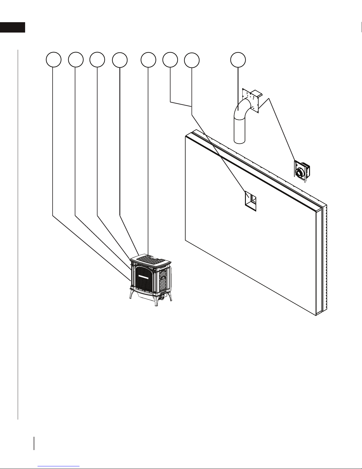
1.2 installation overview
78
6
5
2
1
3
4
6
SAFETY BARRIER
Recommended installation steps:
1. Determine venting requirements before deciding the final location of the appliance.
2. Place the appliance in its final position.
3. Create hole for appliance venting.
4. Install appliance venting (refer to “venting requirements” and “installation” sections).
5. Install all electrical wirings (refer to “wiring diagram” section).
6. Install gas lines (refer to “gas installation” section).
7. Complete finishing (refer to “finishing” section).
8. Test appliance (refer to “gas installation” section).
W415-2207 / B / 02.05.18
Page 7
roof joist. If the appliance is installed directly on carpeting, vinyl tile or other combustible material other than wood fl ooring, the
general information
WARNING
!
• Always light the pilot whether for the first time or if the gas supply has run out, with the glass door opened
or removed.
• Provide adequate clearance for servicing and operating the appliance.
• Provide adequate ventilation.
• Never obstruct the front opening of the appliance.
• Objects placed in front of the appliance must be kept a minimum of 48” (121.9cm) from the front face of
the appliance.
• Surfaces around and especially above the appliance can become hot. Avoid contact when appliance is
operating.
• Fire risk. Explosion hazard.
• High pressure will damage valve. Disconnect gas supply piping before pressure testing gas line at test
pressures above 1/2 PISG (35mb). Close the manual shut-off valve before pressure testing gas line at test
pressures equal to or less than 1/2 PISG (35mb).
• Use only Wolf Steel approved optional accessories and replacement parts with this appliance using nonlisted accessories (blowers, doors, louvres, trims, gas components, venting components, etc.) could result
in a safety hazard and will void the warranty and certification.
• The appliance must not be operated at temperatures below freezing (32ºF/0ºC). Allow the appliance to
warm to above freezing prior to operation.
THIS GAS APPLIANCE MUST BE INSTALLED AND SERVICED BY A QUALIFIED INSTALLER to conform with local
codes. Installation practices vary from region to region and it is important to know the specifi cs that apply to your area, for
example in Massachusetts State:
• This product must be installed by a licensed plumber or gas fi tter when installed within the commonwealth of
Massachusetts.
• The appliance damper must be removed or welded in the open position prior to installation of an appliance insert or gas
log.
• The appliance off valve must be a “T” handle gas cock.
• The fl exible connector must not be longer than 36 inches (0.9m).
• A carbon monoxide detector is required in all rooms containing gas fi red appliances.
• The appliance is not approved for installation in a bedroom or bathroom unless the unit is a direct vent sealed
combustion product.
The installation must conform with local codes or, in absence of local
codes, the National Gas and Propane Installation Code CSA B149.1
in Canada, or the National Fuel Gas Code, ANSI Z223.1 / NFPA 54
in the United States. Suitable for mobile home installation if installed
in accordance with the current standard CAN/CSA Z240MH Series,
for gas equipped mobile homes, in Canada or ANSI Z223.1 and
NFPA 54 in the United States.
The appliance and its individual shutoff valve must be disconnected
from the gas supply piping system during any pressure testing
of that system at test pressures in excess of 1/2 psig (35 mb).
The appliance must be isolated from the gas supply piping system by closing its individual manual shutoff valve during any
pressure testing of the gas supply piping system at test pressures equal to or less than 1/2 psig (35 mb). When installed
with a blower or fan, the junction box must be electrically connected and grounded in accordance with local codes. In the
absence of local codes, use the current CSA C22.1 Canadian Electrical Code in Canada or the ANSI / NFPA 70 National
Electric Code in the United States. In the case where the blower is equipped with a power cord, it must be connected into a
properly grounded receptacle. The grounding prong must not be removed from the cord plug.
The following does not apply to inserts; as long as the required clearance to combustibles is maintained, the most desirable
and benefi cial location for an appliance is in the center of a building, thereby allowing the most effi cient use of the heat
created. The location of windows, doors and, the traffi c fl ow in the room where the appliance is to be located should be
considered. If possible, you should choose a location where the vent will pass through the house without cutting a fl oor or
www.ncertied.org
We suggest that our gas
hearth products be installed
and serviced by professionals
who are certied in the U.S.
by the National Fireplace
®
Institute
(NFI) as NFI Gas
Specialists
EN
appliance shall be installed on a metal or wood panel extending the full width and depth, unless otherwise tested.
W415-2207 / B / 02.05.18
7
Page 8
SAMPLE
EN
general information
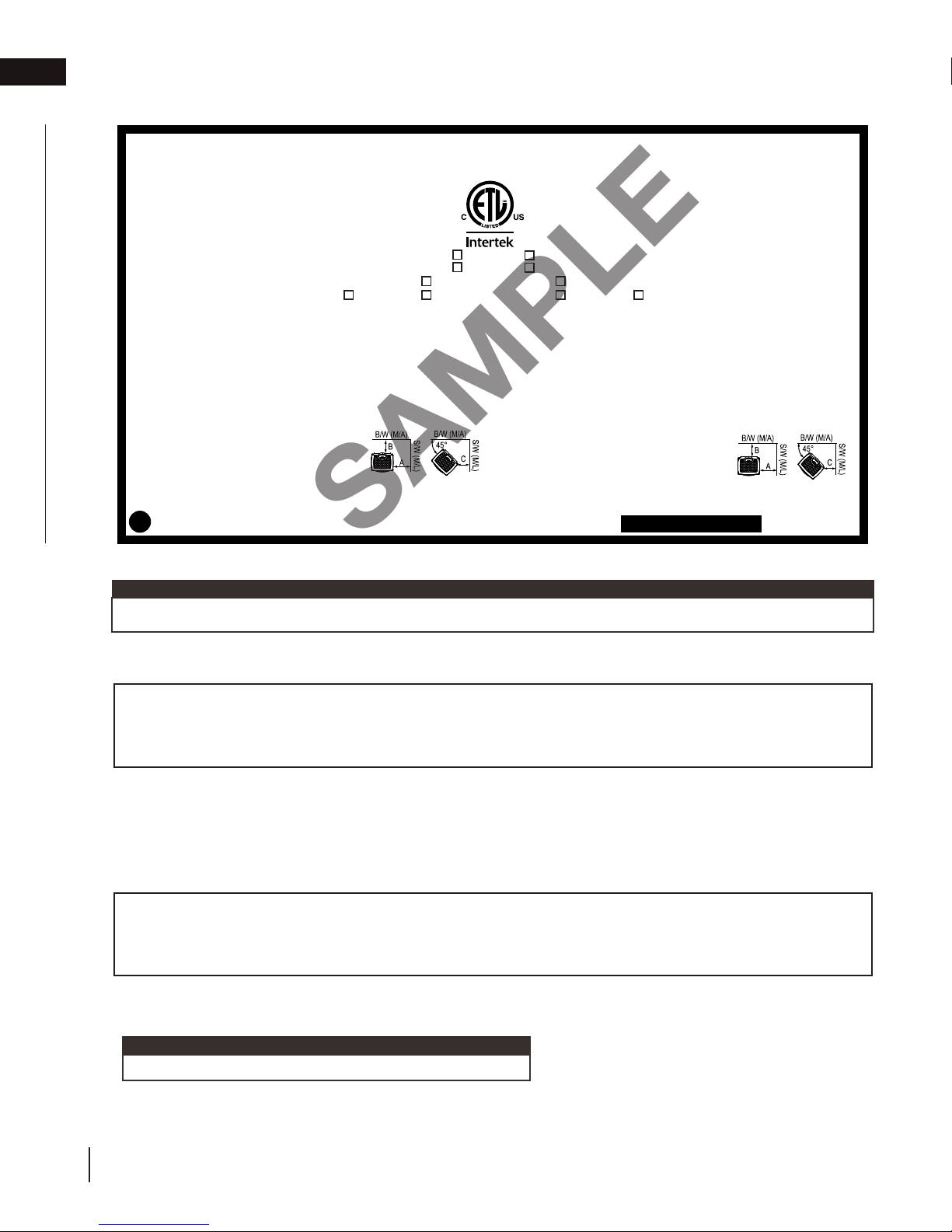
1.3 rating plate information
CONFORMS TO / CONFORME AUX: ANSI Z21.50-2016, CERTIFIED TO / CERTIFIE CSA 2.22-2016 VENTED DECORATIVE GAS APPLIANCE / FOYER À GAZ VENTILÉ.
APPROVED FOR BEDROOM, BATHROOM & BEDSITTING ROOM INSTALLATION. SUITABLE
FOR MOBILE HOME INSTALLATION IF INSTALLED IN ACCORDANCE WITH THE CURRENT
STANDARD CAN/CSA Z240MH SERIES GAS EQUIPPED MOBILE HOMES, IN CANADA
OR IN THE UNITED STATES THE MANUFACTURED HOME CONSTRUCTION AND
SAFETY STANDARD, TITLE 24 CFR, PART 3280. WHEN THIS US STANDARD IS NOT
APPLICABLE USE THE STANDARD FOR FIRE SAFETY CRITERIA FOR MANUFACTURED HOME INSTALLATIONS, SITES AND COMMUNITIES, ANSI / NFPA 501A. FOR
USE WITH BARRIER W010-3295. FOLLOW THE INSTALLATION INSTRUCTIONS
LOCATED IN THE INSTALLATION MANUAL
9700539 (WSL) 4001657 (NGZ)
MANIFOLD PRESSURE: 3.5” W.C. (NG)
4001658 (NAC) 4001659 (WUSA)
PRESSION AU COLLECTEUR: 3.5" D'UNE
COLONNE D'EAU(GN)
MIN SUPPLY PRESSURE: 4.5" W.C.(NG)
0-2000ft 2000-4500ft ALTITUDE / ELEVATION 0-2000ft 2000-4500ft
PRESSION D'ALIMENTATION MIN: 4.5"
D'UNE COLONNE D'EAU (GN)
24,500 BTU/h 22,000 BTU/h INPUT / ALIMENTATION 23,000 BTU/h 20,000 BTU/h
MAX. SUPPLY PRESSURE: 7" W.C. (NG)
19,000 BTU/h 16,000 BTU/h REDUCED INPUT / 16,000 BTU/h 14,000 BTU/h
PRESSION D'ALIMENTATION MAX: 7"
ALIMENTATION REDUITE
D'UNE COLONNE D'EAU (GN)
AFUE: 64%
FOR USE WITH GLASS DOORS CERTIFIED
WITH THIS UNIT ONLY.
WARNING: DO NOT ADD ANY MATERIAL TO
THE APPLIANCE, WHICH WILL COME IN
CONTACT WITH THE FLAMES, OTHER THAN
THAT SUPPLIED BY THE MANUFACTURER
WITH THE APPLIANCE.
ELECTRICAL RATING: 115V 1.5AMP 60HZ
THE APPLIANCE MUST BE VENTED USING
THE APPROPRIATE WOLF STEEL VENT
KITS. SEE OWNERS INSTALLATION MANUAL
FOR VENTING SPECIFICS. MINIMUM AND
MAXIMUM VERTICAL VENT LENGTHS ARE 3
FEET AND 40 FEET RESPECTIVELY.
WOLF STEEL LTD.
24 NAPOLEON ROAD, BARRIE. ONTARIO L4M 0G8 CANADA
NOT FOR USE WITH SOLID FUEL
MINIMUM AND MAXIMUM HORIZONTAL
VENT LENGTHS ARE 10 INCHES AND 20
FEET RESPECTIVELY. PROPER REINSTALLATION AND RESEALING IS NECESSARY
AFTER SERVICING THE VENT-AIR INTAKE
SYSTEM.
MINIMUM CLEARANCE TO COMBUSTIBLE MATERIAL:
A 4"
B 2"
C 2"
VENT TOP 2" TO CEILING FROM
VENT BOTTOM 1" STOVE TOP 48”
VENT SIDES 1"
GDS25N
MODEL
HOMOLOGUE POUR INSTALLATION DANS UNE CHAMBRE A COUCHER, UNE SALLE DE BAIN ET
UN STUDIO. APPROPRIE POUR INSTALLATION DANS UNE MAISON MOBILE SI SON
INSTALLATION CONFORME AUX EXIGENCES DE LA NORME CAN/CSA Z240MH SERIE DE
MAISONS MOBILES EQUIPEES AU GAZ, EN VIGUEUR AU CANADA OU AUX ETATS-UNIS
DE LA NORME DE SECURITE ET DE CONSTRUCTION DE MAISONS MANUFACTUREES,
TITRE 24 CFR, SECTION 3280. DANS LE CAS OU CETTE NORME D'ETATS-UNIS NE PEUT
ETRE APPLIQUEE, SE REFERER A LA NORME RELATIVE AU CRITERE DE MESURES DE
SECURITE CONTRE L'INCENDIE POUR LES INSTALLATIONS DANS LES MAISONS
MANUFACTURES, LES SITES ET LES COMMUNAUTES, ANSI/NFPA 501A. POUR UNE
UTILISER AVEC BARRIÈRE W010-3295. SUIVEZ LES INSTRUCTIONS D'INSTALLATION
GDS25P
UN COMBUSTIBLE SOLIDE NE DOIT PAS ETRE
UTILSE AVEC CET APPAREIL
UTILISER AVEC LES PORTES VITREES
HOMOLOGUEES SEULEMENT AVEC CETTE
UNITE.
AVERTISSEMENT: N'AJOUTEZ PAS A CET
APPAREIL AUCUN MATERIAU DEVANT
ENTRER EN CONTACT AVEC LES FLAMMES
AUTRE QUE CELUI QUI EST FOURNI AVEC
CET APPAREIL PAR LE FABRICANT.
CLASS.: 115V 1.5AMP 60HZ L'APPAREIL
DOIT EVACUER SES GAZ EN UTILISANT
L'ENSEMBLE D'EVACUATION PROPRE A
WOLF STEEL. REFERER AU MANUEL
D'INSTALLATION DE PROPRIETAIRE POUR
L'EVACUATION PRECISE. LES LONGUEURS
VERTICALES MINIMALES ET MAXIMALES
SONT3 PIEDS ET 40 PIEDS
RESPECTIVEMENT.
SERIAL NUMBER / NO. DESERIE
SE TROUVENT DANS LE MANUEL D'INSTALLATION.
GDS25
MANIFOLD PRESSURE: 10” W.C. (LP)
PRESSION AU COLLECTEUR: 10" D'UNE
MIN SUPPLY PRESSURE: 11" W.C.(LP)
PRESSION D'ALIMENTATION MIN: 11"
D'UNE COLONNE D'EAU (P)
MAX. SUPPLY PRESSURE: 13" W.C. (LP)
PRESSION D'ALIMENTATION MAX: 13"
D'UNE COLONNE D'EAU (P)
LES LONGUEURS HORIZONTALES MINIMALES ET
MAXIMALES SONT 10 POUCES ET 20 PIEDS
RESPECTIVEMENT.
IL EST IMPORTANT DE BIEN REINSTALLER ET
RESCELLER L'EVENT APRES AVOIR ASSURE LE
MAINTIEN DU SYSTEME DE PRISE D'AIR.
DEGAGEMENTS MINIMAUX DES MATERIAUX
COMBUSTIBLES:
A 4"
B 2"
C 2"
EVENT SUPERIEUR 2" ENTRE LE DESSUS
DU FOYER
EVENT INFERIEUR 1" ET LE PLAFOND 48”
COTES DE L'EVENT 1"
This illustration is for referece only. Refer to the rating plate on the appliance for accurate information.
note:
The rating plate must remain with the appliance at all times. It must not be removed.
COLONNE D'EAU(P)
AFUE: 64%
W385-1962 / A
1.4 mobile home installation
This appliance must be installed in accordance with the manufacturer’s instructions and the Manufactured
Home Construction and Safety Standard, Title 24 CFR, Part 3280, in the United States or the Mobile Home
Standard, CAN/CSA Z240 MH Series, in Canada. This appliance is only for use with the type(s) of gas
indicated on the rating plate.
This mobile/manufactured home listed appliance comes factory equipped with a means to secure the appliance. Built
in appliances are equipped with 1/4” (6.4mm) diameter holes located in the front left and right corners of the base.
Use appropriate fasteners, inserted through the holes in the base to secure. For free standing products contact your
local authorized dealer / distributor for the appropriate securing kit. For mobile home installations, the appliance must
be fastened in place. It is recommended that the appliance be secured in all installations. Always turn off the pilot and
the fuel supply at the source, prior to moving the mobile home. After moving the mobile home and prior to lighting the
appliance, ensure that the logs are positioned correctly.
This appliance is certifi ed to be installed in an aftermarket permanently located, manufactured (mobile) home,
where not prohibited by local codes.
This appliance is only for use with the type of gas indicated on the rating plate. This appliance is not convertible
for use with other gases, unless a certifi ed kit is used.
Conversion Kits
This appliance is fi eld convertible between Natural Gas (NG) and Propane (P).
To convert from one gas to another, consult your Authorized dealer/distributor.
note:
Conversion kits are not available for Vent Free appliances.
8
W415-2207 / B / 02.05.18
Page 9
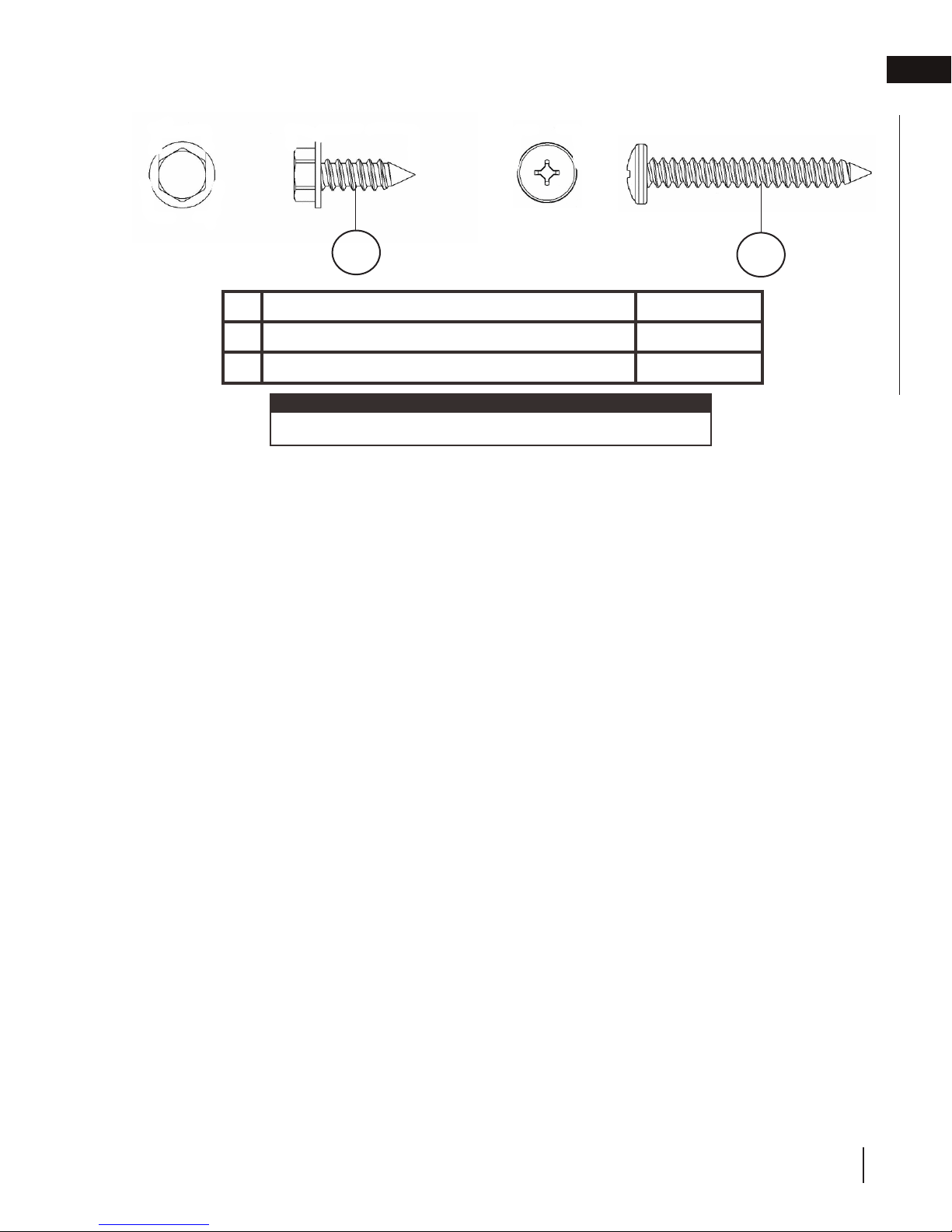
1.5 hardware list
general information
EN
1
Description Quantity
1/4” Hex Head Screw 3
1
1 3/4” Pan Head Screw 4
2
note:
Only fasteners supplied with the appliance are illustrated.
2
W415-2207 / B / 02.05.18
9
Page 10
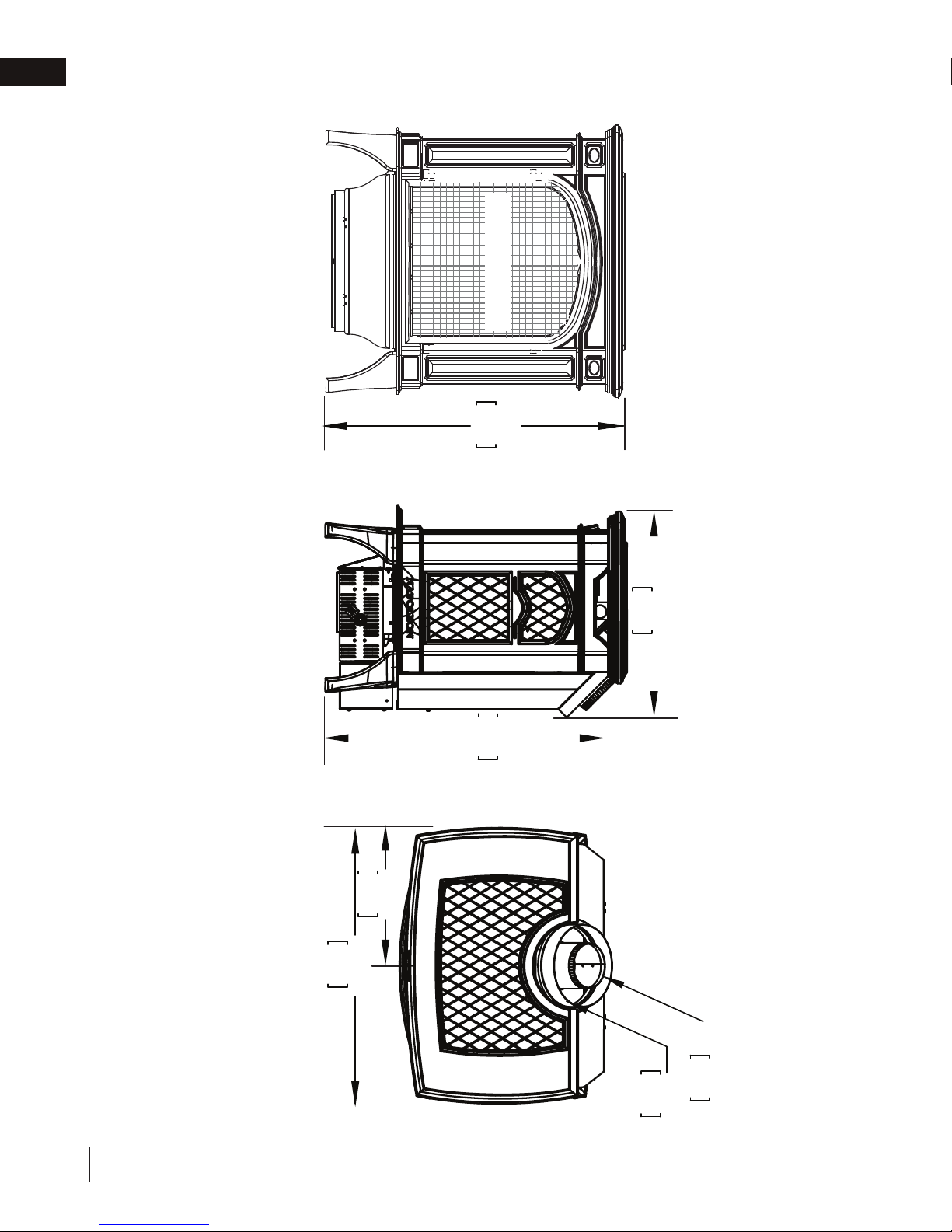
25 5/8"
651mm
23 5/8"
600mm
17 1/2"
445mm
23 1/2"
597mm
12 3/4"
324mm
Ø
4"
102mm
Ø
7"
178mm
SAFETY BARRIER
EN
general information
1.6 dimensions
FRONT VIEW
RIGHT SIDE VIEW
TOP VIEW
10
W415-2207 / B / 02.05.18
Page 11

2.0 venting requirements
WARNING
!
• Risk of fi re. Maintain specifi ed air space clearances to vent pipe and appliance.
• If venting is included with spacers, the vent system must be supported every 3’(0.9m) for both vertical and horizontal runs.
Use support ring assembly W010-0067 or equivalent non-combustible strapping to maintain the minimum clearance to
combustibles for both vertical and horizontal runs. Spacers are attached to the inner pipe at predetermined intervals to
maintain an even air gap to the outer pipe. This gap is required for safe operation. A spacer is required at the start, middle,
and end of each elbow to ensure this gap is maintained. These spaces must not be removed.
This appliance uses a 4” (102mm) exhaust / 7” (178mm) air intake vent pipe system. Refer to the section applicable
to your installation.
For safe and proper operation of the appliance, follow the venting instructions exactly. Deviation from the minimum vertical
vent length can create diffi culty in burner start-up and/or carboning. Under extreme vent confi gurations, allow several minutes
(5-15) for the fl ame to stabilize after ignition. Although not a requirement, it is recommended for vent lengths that pass through
unheated spaces (attics, garages, crawl spaces) be insulated with the insulation wrapped in a protective sleeve to minimize
condensation. Provide a means for visually checking the vent connection to the appliance after the appliance is installed. Use a
fi restop, vent pipe shield or attic insulation shield when penetrating interior walls, fl oor or ceiling.
The vent terminal may be painted with a high temperature paint to match exterior colours. Use an outdoor paint suitable for
400°F (200°C). Application and performance of paint is the consumer’s responsibility. Spot testing is recommended.
note:
If for any reason the vent air intake system is disassembled, re-install per the instructions provided for the initial installation.
note:
This appliance must be installed with a continuous connection of exhaust and air intake vent pipes. Utilizing
alternate constructions such as a chimney as part of the vent system is not permitted.
Use only Wolf Steel, Simpson Dura-Vent, Selkirk Direct Temp, American Metal Amerivent or Metal-Fab venting components.
Minimum and maximum vent lengths, for both horizontal and vertical installations, clearances from vent pipes to combustibles
and air terminal locations as set out in this manual apply to all vent systems and must be adhered to. For Simpson Dura-Vent,
Selkirk Direct Temp, American Metal Amerivent and Metal-Fab, follow the installation procedure provided with the venting
components or on the website for your venting supplier. A starter adaptor must be used with the following vent systems and
may be purchased from the corresponding supplier:
EN
Vent
Manufacturer
Duravent W175-0053 Wolf Steel www.duravent.com
Amerivent 4DSC-N2 American Metal www.americanmetalproducts.com
Direct Temp 4DT-AAN Selkirk www.selkirkcorp.com
SuperSeal 4DNA Metal-Fab www.mtlfab.com
For vent systems that provide seals on the inner exhaust fl ue, only the outer air intake joints must be sealed using a red high
temperature silicone (RTV). This same sealant may be used on both the inner exhaust and outer intake vent pipe joints of all
other approved vent systems except for the exhaust vent pipe connection to the appliance fl ue collar which must be sealed
using the black high temperature sealant Mill Pac. High temperature sealant must be ordered separately.
When using Wolf Steel venting components, use only approved Wolf Steel rigid / fl exible components with the following termination kits: wall terminal kit GD-222, GD-222R, or 1/12 to 7/12 pitch roof terminal kit GD-110, 8/12 to 12/12 roof terminal
kit GD-111, fl at roof terminal kit GD-112 or periscope kit GD-201 (for wall penetration below grade). With fl exible venting, in
conjunction with the various terminations, use either the 5 foot (1.5m) vent kit GD-220 or the 10 foot (3.1m) vent kit GD-330.
For stoves only: wall terminal kit GD-175 (venting included).
Starter Adapter Part Number Supplier Website
W415-2207 / B / 02.05.18
11
Page 12

!
WARNING
• Risk of fi re. Maintain specifi ed air space clearances to vent pipe and appliance.
• If venting is included with spacers, the vent system must be supported every 3’(0.9m) for both vertical and horizontal runs.
Use support ring assembly W010-0067 or equivalent non-combustible strapping to maintain the minimum clearance to
combustibles for both vertical and horizontal runs. Spacers are attached to the inner pipe at predetermined intervals to
maintain an even air gap to the outer pipe. This gap is required for safe operation. A spacer is required at the start, middle,
and end of each elbow to ensure this gap is maintained. These spaces must not be removed.
This appliance uses a 4” (102mm) exhaust / 7” (178mm) air intake vent pipe system. Refer to the section applicable
to your installation.
For safe and proper operation of the appliance, follow the venting instructions exactly. Deviation from the minimum vertical
vent length can create diffi culty in burner start-up and/or carboning. Under extreme vent confi gurations, allow several minutes
(5-15) for the fl ame to stabilize after ignition. Although not a requirement, it is recommended for vent lengths that pass through
unheated spaces (attics, garages, crawl spaces) be insulated with the insulation wrapped in a protective sleeve to minimize
condensation. Provide a means for visually checking the vent connection to the appliance after the appliance is installed. Use a
fi restop, vent pipe shield or attic insulation shield when penetrating interior walls, fl oor or ceiling.
The vent terminal may be painted with a high temperature paint to match exterior colours. Use an outdoor paint suitable for
400°F (200°C). Application and performance of paint is the consumer’s responsibility. Spot testing is recommended.
For vent systems that provide seals on the inner exhaust fl ue, only the outer air intake joints must be sealed using a red high
temperature silicone (RTV). This same sealant may be used on both the inner exhaust and outer intake vent pipe joints of all
other approved vent systems except for the exhaust vent pipe connection to the appliance fl ue collar which must be sealed
using the black high temperature sealant Mill Pac. High temperature sealant must be ordered separately.
For optimum fl ame appearance and appliance performance, keep the vent length and number of elbows to a minimum.
Vent
Manufacturer
Starter Adapter Part Number Supplier Website
Duravent W175-0053 Wolf Steel www.duravent.com
Amerivent 4DSC-N2 American Metal www.americanmetalproducts.com
Direct Temp 4DT-AAN Selkirk www.selkirkcorp.com
SuperSeal 4DNA Metal-Fab www.mtlfab.com
Use only Wolf Steel, Simpson Dura-Vent, Selkirk Direct Temp, American Metal Amerivent or Metal-Fab venting components.
Minimum and maximum vent lengths, for both horizontal and vertical installations, clearances from vent pipes to combustibles
and air terminal locations as set out in this manual apply to all vent systems and must be adhered to. For Simpson Dura-Vent,
Selkirk Direct Temp, American Metal Amerivent and Metal-Fab, follow the installation procedure provided with the venting
components or on the website for your venting supplier. A starter adaptor must be used with the following vent systems and
may be purchased from the corresponding supplier:
note:
If for any reason the vent air intake system is disassembled, re-install per the instructions provided for the initial installation.
note:
This appliance must be installed with a continuous connection of exhaust and air intake vent pipes. Utilizing
alternate constructions such as a chimney as part of the vent system is not permitted.
This template must be used in conjunction with templates 7.1.1 or 7.1.2, depending on
termination shape (i.e. round, or round and square). See appropriate templates folder.
EN
venting requirements
The air terminal must remain unobstructed at all times. Examine the air terminal at least once a year to verify that
it is unobstructed and undamaged.
Rigid and fl exible venting systems must not be combined. Different venting manufacturer components must not
be combined.
These vent kits allow for either horizontal or vertical venting of the appliance. The maximum allowable horizontal run is 20
feet (6.1m). The maximum allowable vertical vent length is 40 feet (12.2m). The maximum number of vent connections is two
horizontally or three vertically (excluding the appliance and the air terminal connections) when using fl exible venting.
Horizontal runs may have a 0” rise per foot or 0mm rise per meter however for optimum performance it is recommended
that all horizontal runs have a minimum 1/4” rise per foot or 21mm rise per meter using fl exible venting. For safe and proper
operation of the appliance, follow the venting instructions exactly.
A terminal shall not terminate directly above a sidewalk or paved driveway which is located between two single family dwellings
and serves both dwellings. Local codes or regulations may require different clearances.
Do not allow the inside liner to bunch up on horizontal or vertical runs and elbows. Keep it pulled tight. A 1¼” (31.8mm) air gap
all around between the inner liner and outer liner is required for safe operation.
12
W415-2207 / B / 02.05.18
Page 13
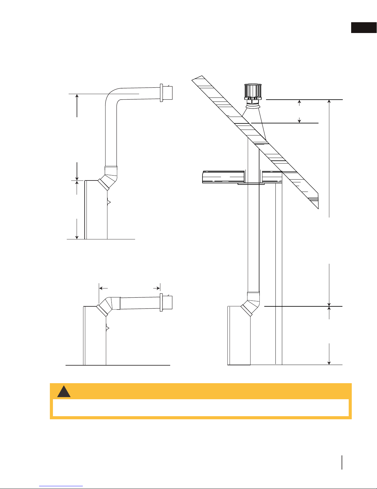
2.1 typical venting installation
24” (61cm) MIN.
REGARDLESS OF
HORIZONTAL VENT
LENGTH
25 5/8”
(65.1cm)
venting requirements
16” (40.6cm)
EN
40FT (12m)
MAX
3FT (1m)
MIN
24” (61cm)
MAXIMUM
25 5/8”
(65.1cm)
WARNING
!
• The maximum horizontal run with a 57” (1.45m) vertical rise immediately above the appliance is 20 feet
(6.1m).
W415-2207 / B / 02.05.18
13
Page 14
EN
venting requirements
2.2 special vent installations
2.2.1 periscope termination
Use the periscope kit to locate the air termination above grade. The periscope must
be installed so that when fi nal grading is completed, the bottom air slot is located a
minimum of 12” (305mm) above grade. The maximum allowable vent length is
10’ (3.1m) for a fi replace and 8’ (2.4m) for a stove.
WARNING
!
• Below grade installation maximum
8ft (2.4m) vent length.
• Use GD201 periscope kit.
• Horizontal run not to exceed vertical rise.
12”
(305mm) MIN
TO GRADE
24” (610mm) MIN.
REGARDLESS OF OF
HORIZONTAL VENT
LENGTH
25 5/8”
(651mm)
2.2.2 corner termination
SAFETY
BARRIER
24” (610mm)
MAX.
14
W415-2207 / B / 02.05.18
Page 15
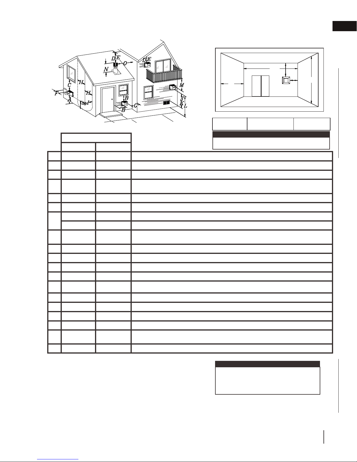
2.3 vent terminal clearances
Covered balcony applications
venting requirements
R
EN
††*
Q
S
P
G
Q
= 3 feet
MIN
(0.9m)
INSTALLATIONS
CANADA U.S.A.
12” (30.5cm) 12” (30.5cm) Clearance above grade, veranda porch, deck or balcony.
A
Δ
12” (30.5cm)
B
12” (30.5cm)* 12” (30.5cm)* Clearance to permanently closed windows.
C
D
E
F
G
H
I
J
K
L
M
18”
(45.7cm)**
12” (30.5cm)** 12” (30.5cm)** Clearance to unventilated soffi t.
0” (0mm) 0” (0mm) Clearance to an outside corner wall.
0” (0mm)*** 0” (0mm)***
2” (51mm)*** 2” (51mm)*** Clearance to an inside combustible corner wall or protruding combustible obstructions (vent chase, etc.).
3’(0.9m) 3’(0.9m)****
3’ (0.9m) 3’ (0.9m)**** Clearance to a service regulator vent outlet.
12” (30.5cm) 9” (229mm) Clearance to a non-mechanical air supply inlet to the building or a combustion air inlet to any other appliance.
6’ (1.8m) 3’ (0.9m) † Clearance to a mechanical air supply inlet.
7’ (2.1m) ‡ 7’ (2.1m) **** Clearance above a paved sidewalk or paved driveway located on public property.
12” (30.5cm)†† 12” (30.5cm)**** Clearance under a veranda, porch or deck.
9” (229mm) ΔClearance to windows or doors that open.
18”
(45.7cm)**
Vertical clearance to ventilated soffi ts located above the terminal within a horizontal distance of 2’
(0.6m) from the center line of the terminal.
Clearance to an inside non-combustible corner wall or protruding non-combustible obstructions (chimney, etc.).
Clearance to each side of the center line extended above the meter / regulator assembly to a maximum vertical distance of 15’ (4.6m).
note:
Wall terminals are for illustration purposes only. Size and
shapes may vary.
R
= 2 x
MAX
Q
ACTUAL
R
MAX
≤ 15 feet
(4.6m)
16” (40.6cm) 16” (40.6cm) Clearance above the roof.
N
2’ (0.6m)†* 2’ (0.6m) †* Clearance from an adjacent wall including neighbouring buildings.
O
8’ (2.4m) 8’ (2.4m)
P
3’ (0.9m) 3’ (0.9m) See chart for wider wall dimensions.
Q
6’ (1.8m) 6’ (1.8m)
R
12” (30.5cm) 12” (30.5cm) Clearance under a covered balcony
S
Δ The terminal shall not be located less than 6 feet under a window that opens on a horizontal plane in a structure with three walls and a roof.
* Recommended to prevent condensation on windows and thermal breakage
** It is recommended to use a heat shield and to maximize the distance to vinyl clad soffi ts.
*** The periscope requires a minimum 18 inches clearance from an inside corner.
**** This is a recommended distance. For additional requirements, check local codes.
† 3 feet above if within 10 feet horizontally.
‡ A vent shall not terminate where it may cause hazardous frost or ice accumulations on adjacent property surfaces.
†† Permitted only if the veranda, porch, or deck is fully open on a minimum of two sides beneath the fl oor.
†* Recommended to prevent recirculation of exhaust products. For additional requirements, check local codes.
††* Permitted only if the balcony is fully open on a minimum of one side.
Roof must be non-combustible without openings.
See chart for deeper wall dimensions. The terminal shall not be installed on any wall that has an
opening between the terminal and the open side of the structure.
note:
Clearances are to be in accordance with local
installation codes and the requirements of the gas
supplier. In their absence, clearances are to be as
listed above and are based on national codes.
W415-2207 / B / 02.05.18
15
Page 16

EN
venting requirements
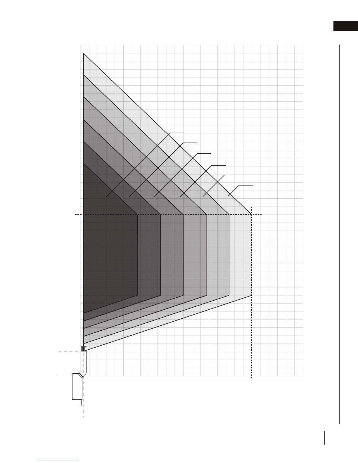
2.4 horizontal termination
39’ 2”
V
V+H ≤ 40 ft. (For longer vent runs, a power
vent is required).
H ≤ 20 ft.
V + H are measured from the centre of vent
elbows. Elbows are considered as 90º.
Two 45º elbows = One 90º elbow.
5 1/2 elbow zone
30’
4 1/2 elbow zone
3 1/2 elbow zone
2 1/2 elbow zone
1 1/2 elbow zone*
20’
4”
MAXIMUM
57”
24”
MINIMUM
0’
Centre of
Base of Air
Collar
15’
10’
5’
0’
10”
24”
MAXIMUM
5’
10’
15’
20’
25’
H
* 1 1/2 elbows constitute the 45°
elbow directly off the appliance
and an additional 90° elbow.
16
W415-2207 / B / 02.05.18
Page 17
2.5 vertical termination
venting requirements
EN
V
20’
40’
30’
V+H ≤ 40 ft. (For longer vent runs, a power
vent is required).
H ≤ 20 ft.
V + H are measured from the centre of vent
elbows. Elbows are considered as 90º.
Two 45º elbows = One 90º elbow.
6 1/2 elbow zone
5 1/2 elbow zone
4 1/2 elbow zone
3 1/2 elbow zone
2 1/2 elbow zone
1 1/2 elbow zone*
3’
MINIMUM
0’
Centre of
Base of Air
Collar
15’
10’
5’
0’
4”
MINIMUM
5’
10’
15’
20’
25’
H
* 1 1/2 elbows constitute the 45°
elbow directly off the appliance
and an additional 90° elbow.
W415-2207 / B / 02.05.18
17
Page 18
!
WARNING
EN
venting requirements
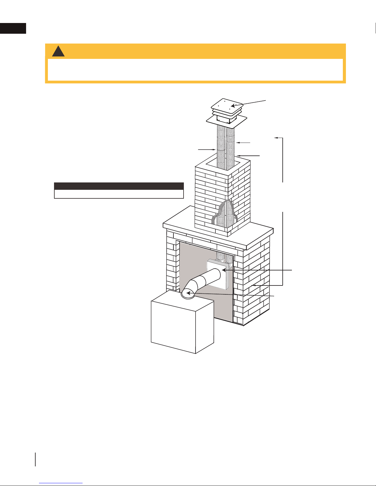
2.6 vertical through existing chimney
• Risk of fi re.
• Co-axial to co-linear venting confi gurations must only be used in a non-combustible chimney or enclosure.
Installation in a combustible enclosure could result in a fi re.
This appliance is designed to be attached to a 3” (76.2mm) co-linear aluminum fl ex vent system running the full
length of a masonry chimney.
The fl ex liners accommodate any contours of a
masonry chimney, however, it is necessary to keep
the fl exible liners as straight as possible. The inlet
air collar of the termination cap must be connected
to the air intake fl ex liner and the exhaust collar
must be connected to the exhaust fl exible liner.
Both Simpson Duravent and Selkirk co-linear to
co-axial adaptors have been approved on this
appliance
AIR
INTAKE
TERMINATION
EXHAUST
FLUE
FLEX
LINER
note:
A vent adaptor will be required directly off the appliance.
Follow vent manufacturer’s installation instructions.
Different manufacturer’s venting
components must not be combined.
Once the preferred manufacturer’s
appliance adaptor has been attached, the
remainder of the system must be that of
the same manufacturer.
The only exception to this rule is to use
Wolf Steel’s approved 3” (76.2mm) fl ex
liner and co-linear termination.
* Measured from appliance fl ue collar
to termination fl ue collar
* 40 FT (12.2m)
MAX.
10 FT (3.1m)
MIN
COAXIAL TO
CO-LINEAR
ADAPATOR
APPLIANCE
VENT ADAPTOR
18
W415-2207 / B / 02.05.18
Page 19

3.0 installation
!
WARNING
• Ensure to unpack all loose materials from inside the fi rebox prior to connecting the gas and electrical supply
• If your appliance is supplied with a remote, ensure the remote receiver is in the “OFF” position prior
to connecting the gas and electrical supply to the appliance.
• For safe and proper operation of the appliance, follow the venting instructions exactly.
• The appliance exhaust fl ue collar must be sealed using Mill Pac. All exhaust and intake vent pipe joints
must be sealed using red RTV high temp silicone sealant (W573-0002) (not supplied) or black high temp Mill
Pac (W573-0007) (not supplied).
• If using pipe clamps to connect rigid vent components, a minimum of 3 screws must also be used to ensure
the connection cannot slip off.
• Do not clamp the fl exible vent pipe.
• Risk of fi re, explosion, or asphyxiation. Improper support of the entire venting system may allow vent to sag
and separate. Use vent run supports and connect vent sections per installation instructions.
• Risk of fi re, do not allow loose materials or insulation to touch the vent pipe. Remove insulation to allow for the
installation of the attic shield and to maintain clearances to combustibles.
• Do not fi ll the space between the vent pipe and enclosure with any type of material. Do not pack insulation
or combustibles between ceiling fi restops. Always maintain specifi ed clearances around venting and fi restop
systems. Install wall shields and fi restops as specifi ed. Failure to keep insulation or other materials away from
vent pipe may cause fi re.
EN
W415-2207 / B / 02.05.18
19
Page 20
This application occurs when venting through a roof. Installation kits for
WARNING
EN
installation
3.1 horizontal installation
!
• The fi restop assembly must be installed with the vent shield to the top.
• Terminals must not be recessed into a wall or siding more than the depth of the return fl ange of the mounting
plate.
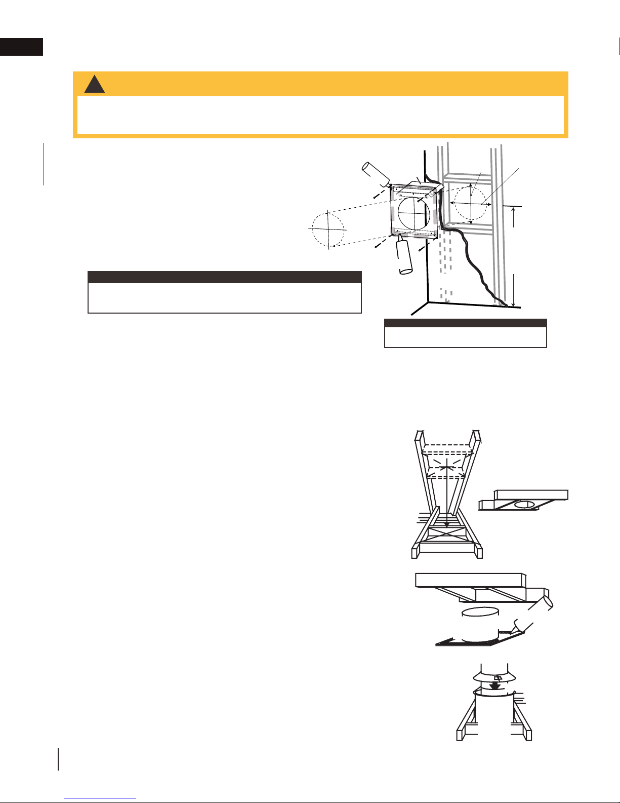
This application occurs when venting through an exterior
wall. Having determined the correct height for the air
terminal location, cut and frame a hole in the exterior wall,
as illustrated, to accommodate the fi restop assembly. Dry
fi t the fi restop assembly before proceeding to ensure the
brackets on the rear surface fi t to the inside surface of the
horizontal framing.
The length of the vent shield may be cut shorter for
combustible walls that are less than 8 1/2” (215.9mm)
thick but the vent shield must extend the full depth of the
combustible wall.
note:
Do not fi ll the air space between the fi restop spacer and the
exterior wall with any type of insulating material (i.e. spray foam).
A. Assemble the shield to the spacer as shown, using the 3
shorter screws supplied.
B. Place the fi restop top so that the vent shield covers the top of
the vent within the opening. Ensure that both spacer and shield
maintain the required clearance to combustibles.
C. Secure the spacer in place using the 4 longer screws supplied.
Once the vent pipe is installed in its fi nal position, apply sealant between the pipe and the fi restop spacer.
3.2 vertical installation
CAULKING
FIRESTOP
SPACER
CAULKING
10 11/16”
ADD
(27.14cm)
VENT
SHIELD
note:
The above is for illustration purposes only. Vents
do not always pass through center of frame.
HEIGHT
HIGH
FINISHING
MATERIAL
10 11/16”
ADD
(27.14cm)
WIDTH
WIDE
DETERMINE
THE
CORRECT
HEIGHT
various roof pitches are available from your authorized dealer / distributor.
See the “accessories” section to order specifi c kits required.
A. Determine the air terminal location, cut and frame a square opening,
as illustrated, in the ceiling and the roof to provide the minimum 1"
(25mm) clearance between the vent pipe and any combustible material.
Try to center the vent pipe location midway between two joists to
prevent having to cut them. Use a plumb bob to line up the center of
the openings. A vent pipe shield will prevent any materials such as
insulation, from fi lling up the 1" (25mm) air space around the pipe. Nail
headers between the joist for extra support.
B. Apply a bead of caulking (not supplied) to the framework or to the
Wolf Steel vent pipe shield plate or equivalent (in the case of a fi nished
ceiling), and secure over the opening in the ceiling. A fi restop must be
placed on the bottom of each framed opening in a roof or ceiling that
the venting system passes through. Apply a bead of caulking all around
and place a fi restop spacer over the vent shield to restrict cold air from
being drawn into the room or around the fi replace. Ensure that both
spacer and shield maintain the required clearance to combustibles.
Once the vent pipe is installed in its fi nal position, apply Mill Pac sealant
(W573-0007) (not supplied) or red RTV silicone (W573-0002) (not
supplied) between the pipe and the fi restop assembly.
C. In the attic, slide the vent pipe collar down to cover up the open end
of the shield and tighten. This will prevent any materials, such as
insulation, from fi lling up the 1" (25mm) air space around the pipe.
Vent Pipe
Shield
Vent
Pipe
Shield
Firestop
underside
of joist
Caulking
Vent
Pipe
Collar
20
W415-2207 / B / 02.05.18
Page 21
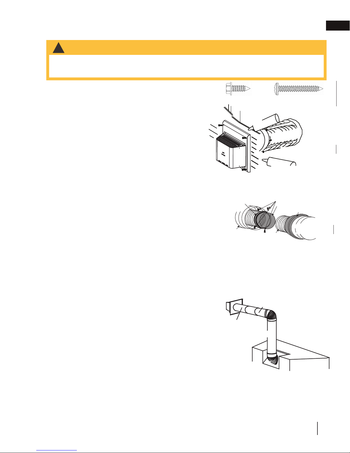
3.3 horizontal air terminal installation
A. Stretch the inner fl ex pipe to the required length taking
depth of its return fl ange.
ADD FASTENER TYPE
Pipe
Telescopic sleeve
Venting
TOP VENT
20" (51cm)
Coupler
REAR VENT
Air terminal
Air terminal
Telescopic sleeve
20" (51cm)
Coupler
Venting
WARNING
!
• Terminals must not be recessed into a wall or siding more than the depth of the return flange of the
mounting plate.
• Do not allow the inner flex pipe to bunch up on horizontal or vertical runs and elbows. Keep it pulled tight.
into account the additional length needed for the fi nished
wall surface. Apply a heavy bead of the red RTV silicone
(W573-0002) (not supplied) to the inner sleeve of the air
terminal. Slip the vent pipe a minimum of 2” (50.8mm)
over the inner sleeve of the air terminal and secure with a
minimum of 3 screws.
B. Using the outer fl ex pipe, slide over the outer combustion
air sleeve of the air terminal and secure with a minimum
of 3 screws. Seal using red RTV silicone (W573-0002)
(not supplied).
C. Insert the vent pipes through the fi restop maintaining
the required clearance to combustibles. Holding the air
terminal (lettering in an upright, readable position), secure
to the exterior wall and make weather tight by sealing
with caulking (not supplied).
D. If more vent pipe needs to be used to reach the fi replace,
E. Stove Appliances Only: From inside the house, using
The air terminal mounting plate may be recessed into the exterior wall or siding no greater than the
couple them together, as illustrated. The vent system
must be supported approximately every 3 feet (0.9m) for
both vertical and horizontal runs. Use non-combustible
strapping to maintain the minimum clearance to
combustibles.
Red RTV Silicone (W573-0002) (not supplied), seal
between the vent pipe and the fi restop. Then slide the black trim collar over the vent pipe up to the
fi restop.
Type 1 (x3)
Caulking
Screws
(Supplied)
Red RTV Silicone
Outer Flex
Pipe
ADD GRAPHIC
installation
Type 2 (x4)
Inner Flex
Pipe
Outer Rigid Pipe
2" (50.8mm) Overlap
Red RTV Silicone
Inner Flex
Outer Flex Pipe
Screws
Inner Coupler
Outer Coupler
Outer Rigid
Outer Flex
Pipe
Pipe
EN
3.4 extended horizontal and corner air terminal installation
FOR REAR VENT ONLY: A 45° corner installation can have 0” (0mm)
rise between the appliance combustion air collar and the air terminal.
In this case, vent lengths must be kept to a maximum of 24” (61cm).
For longer vent lengths, a minimum vertical rise of 24” (61cm) is required.
A. Follow the instructions for "horizontal air terminal installation" section.
B. Continue adding components alternating inner rigid pipe and outer
rigid pipe. Ensure that all inner rigid pipe and elbows have sufficient
vent spacers attached and each component is sealed and securely
fastened to the one prior. Attach the inner telescopic sleeve to the
vent run. Repeat using the outer telescopic sleeve. Seal and secure
as before. To facilitate completion, attach inner and outer couplers
to the air terminal.
C. Install the air terminal. See “horizontal air terminal installation” section.
Extend the outer telescopic sleeve; connect to the air terminal assembly.
Fasten with self tapping screws and seal.
AIR TERMINAL
20" (508mm)
COUPLER
TELESCOPIC SLEEVE
VENTING
Add Image
W415-2207 / B / 02.05.18
21
Page 22
air terminal installation” section.
!
WARNING
EN
installation
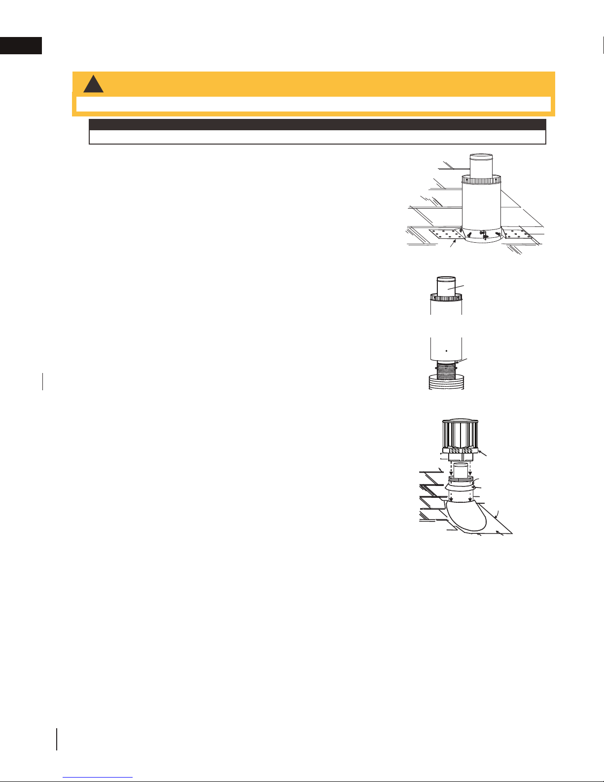
3.5 vertical air terminal Installation
• Maintain a minimum 2” (51mm) space between the air inlet base and the storm collar.
note:
Fastening hardware provided with appropriate roof terminal and liner kits.
A. Fasten the roof support to the roof using 6 screws. The roof support is
optional. In this case, the venting is to be adequately supported using
either an alternate method suitable to the authority having jurisdiction or
the optional roof support.
B. Stretch the inner fl ex pipe to the required length. Slip the inner fl ex
pipe a minimum of 2” (51mm) over the inner pipe of the air terminal
connector and secure with a minimum of three screws, when 4/7, 5/8
and 3/5 venting is used and a minimum of six screws when using 8/10
or 8/11 venting. Seal using a heavy bead of red RTV silicone (W573-
0002) (not supplied).
C. Repeat using the outer fl ex pipe, using a heavy bead of red RTV
silicone (W573-0002) (not supplied) and a minimum of three screws,
when 4/7, 5/8 and 3/5 venting is used and a minimum of six screws
when using 8/10 or 8/11 venting.
D. Thread the air terminal connector / vent pipe assembly down through
the roof. The air terminal must be positioned vertically and plumb.
Attach the air terminal connector to the roof support, ensuring that the
top of the air terminal is 16” (40.6cm) above the highest point that it
penetrates the roof.
E. Remove nails from the shingles, above and to the sides of the air
terminal connector. Place the fl ashing over the air terminal connector
leaving a min. 3/4” (19mm) of the air terminal connector showing above
the top of the fl ashing. Slide the fl ashing underneath the sides and
upper edge of the shingles. Ensure that the air terminal connector is
properly centered within the fl ashing, giving a 3/4” (19mm) margin all
around. Fasten to the roof. Do not nail through the lower portion of the
fl ashing. Make weather-tight by sealing with caulking. Where possible,
cover the sides and top edges of the fl ashing with roofi ng material.
F. Aligning the seams of the terminal and air terminal connector, place the
terminal over the air terminal connector making sure the vent pipe goes
into the hole in the terminal. Secure with a minimum of three screws,
when 4/7, 5/8 and 3/5 venting is used and a minimum of six screws
when using 8/10 or 8/11 venting.
G. Apply a heavy bead of weatherproof caulking 2” (51mm) above the
fl ashing. Install the storm collar around the air terminal and slide down
to the caulking. Tighten to ensure that a weather-tight seal between the
air terminal and the collar is achieved.
H. If more vent pipe needs to be used to reach the appliance, see “horizontal
Connector
2” (51mm)
Roof Support
Air
Terminal
Inner Flex Pipe
Inner Pipe
Red RTV
Silicone
(W572-0002)
Outer Flex Pipe
Outer Rigid Pipe
Air Inlet
Base
Caulking
Sto r m Collar
Weather
Sealant
Flashing
22
W415-2207 / B / 02.05.18
Page 23

3.6 appliance vent connection
A. Attach the adjustable pipe to the last section of rigid pipe. Secure with
!
WARNING
• Check for gas leaks by brushing on a soap and water solution. Do not use open fl ame.
screws and seal.
B. Install the inner fl ex pipe to the appliance. Secure with a minimum of
three screws and fl at washers when installing 3”/5”, 4”/7” or 5”/8”
venting, or six screws and fl at washers when installing 8”/10” or
8”/11” venting. Seal the joint and screw holes using Mill Pac sealant
(W573-0007) (not supplied).
C. Run a bead of high temperature red RTV silicone (W573-0002) (not
supplied) around the inside of the air intake collar. Pull the adjustable
pipe a minimum 2” (50.8mm) into the air intake collar.
note:
Always fi nish vent system installation with the appliance vent connection. Ensure that the sealant is not visible on the
exterior pipes once installation is completed. An optional decorative black band may be available with this appliance.
In the event that the venting must be disassembled, care must be taken to reseal the venting.
3.7 gas installation
• Risk of fi re, explosion, or asphyxiation. Ensure there are no ignition sources such as sparks or open fl ames.
• Support gas control when attaching gas supply pipe to prevent damaging gas line.
• Always light the pilot whether for the fi rst time or if the gas supply has run out with the glass door opened
or removed. Purging of the gas supply line should be performed by a qualifi ed service technician. Ensure
that a continuous gas fl ow is at the burner before closing the door. Ensure adequate ventilation. For gas and
electrical locations, see “dimensions” section.
• All gas connections must be contained within the appliance when complete (gas fi replaces only).
• High pressure will damage valve. Disconnect gas supply piping before testing gas line at test pressures above
1/2 PSIG.
• Valve settings have been factory set, do not change.
installation
#8 X 1/2”
Self Drilling
Screws
INSERT
2” (50.8mm)
IMAGE HERE
Overlap
High Temperature
Sealant
EN
Installation and servicing to be done by a qualifi ed installer.
• Move the appliance into position and secure.
• If equipped with a fl ex connector, the appliance is designed to accept a 1/2” (13mm) gas supply. Without the
connector, it is designed to accept a 3/8” (9.5mm) gas supply. The appliance is equipped with a manual shut
off valve to turn off the gas supply to the appliance.
• Connect the gas supply in accordance to local codes. In the absence of local codes, install to the current
CAN/CSA-B149.1 Installation Code in Canada or to the current National Fuel Gas Code, ANSI Z223.1 / NFPA
54 in the United States.
• When fl exing any gas line, support the gas valve so that the lines are not bent or kinked.
• The gas line fl ex-connector should be installed to provide suffi cient movement for shifting the burner assembly
on its side to aid with servicing components.
W415-2207 / B / 02.05.18
23
Page 24
MINIMUM CLEARANCE TO COMBUSTIBLES MUST BE MAINTAINED OR A SERIOUS FIRE HAZARD
COULD RESULT.
ENTIRELY OF NON-COMBUSTIBLE MATERIALS (I.E. STEEL STUDS, CEMENT BOARD, ETC.).
NEVER OBSTRUCT THE FRONT OPENING OF THE APPLIANCE.
!
WARNING
EN
installation
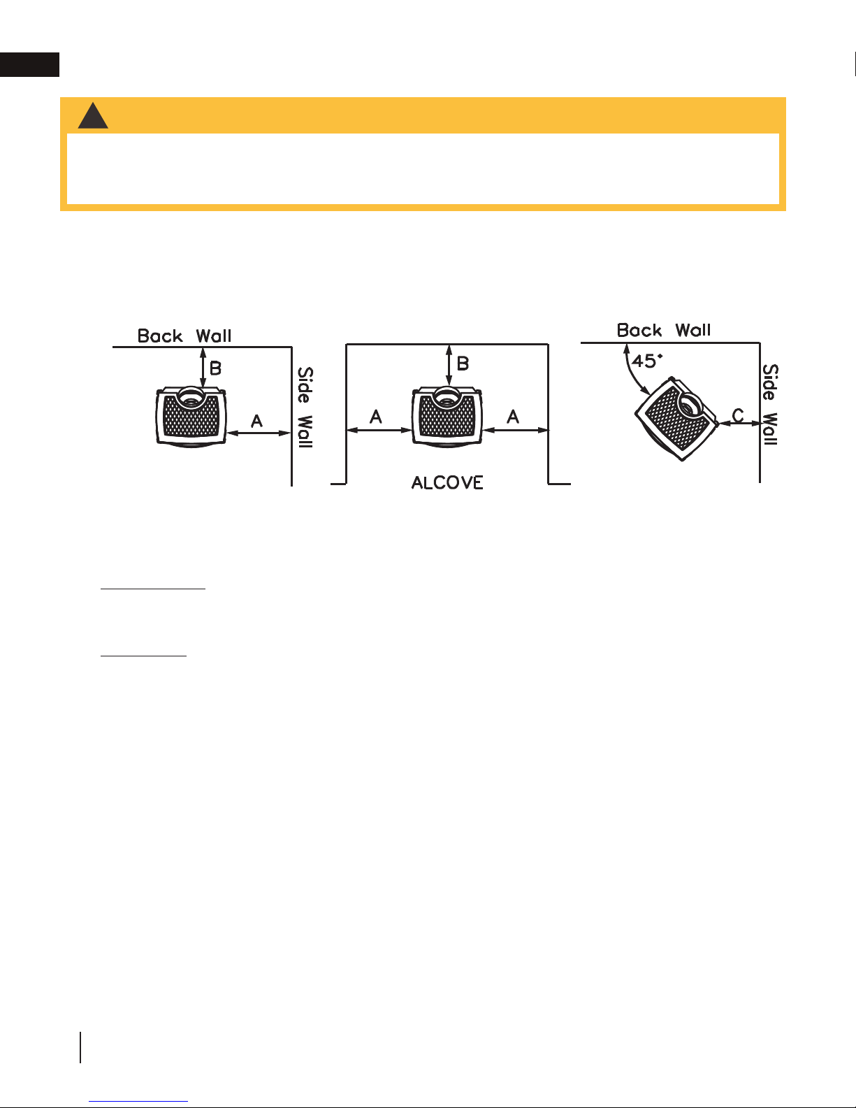
3.8 minimum clearance to combustibles
WARNING
!
• Minimum clearance to combustibles must be maintained or a serious fire hazard could result.
• Framing or finishing materials closer than the minimums listed must be constructed entirely of non-combustible materials (i.e. steel studs, cement board, etc.).
• Never obstruct the front opening of the appliance.
As long as clearance to combustibles is kept within the required distances, the most desirable and beneficial
location for a Napoleon® appliance is in the centre of a building, thereby allowing the most efficient use of the
heat created. The location of windows, doors and the traffic flow in the room where the appliance is to be located
should be considered. If possible, you should choose a location where the vent will pass through the house without cutting a floor or roof joist.
A. 4” (102mm) B. 2” (51mm)* C. 2” (51mm)
To ceiling from appliance top 48” (1219mm)
Horizontal vent:
Sides and bottom 1” (25mm)
Top 2” (51mm)
Vertical vent:
All sides 1” (25mm)
*At a distance of 2” (51mm) from the wall, installation or service to the blower may not be practical. A minimum of
5” (127mm) will be required in order to install the blower.
If less than 5” (127mm) clearance is maintained between the back of the appliance and the back wall, it will be
necessary to disconnect the venting and gas pipe to move the appliance out for installation or service of the
blower.
24
W415-2207 / B / 02.05.18
Page 25
COMBUSTIBLE
MANTE
TRIM M
ETC.) ARE CLEARLY MAINTAINED.
!
WARNING
25
EN
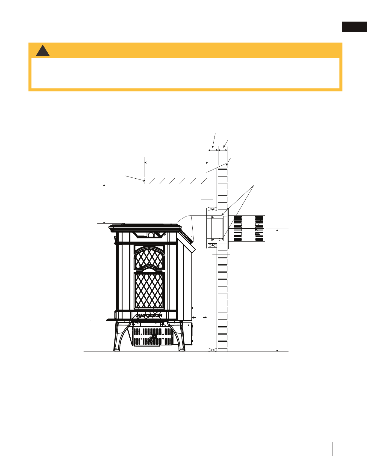
3.9 minimum mantel or shelf clearances
WARNING
!
• Risk of fire!
• Maintain all specified air space clearances to combustibles.
• Failure to comply with these instructions may cause a fire or cause the appliance to overheat.
• Ensure all clearances (i.e. back, side, top, vent, hearth, mantel, front, etc.) are clearly maintained.
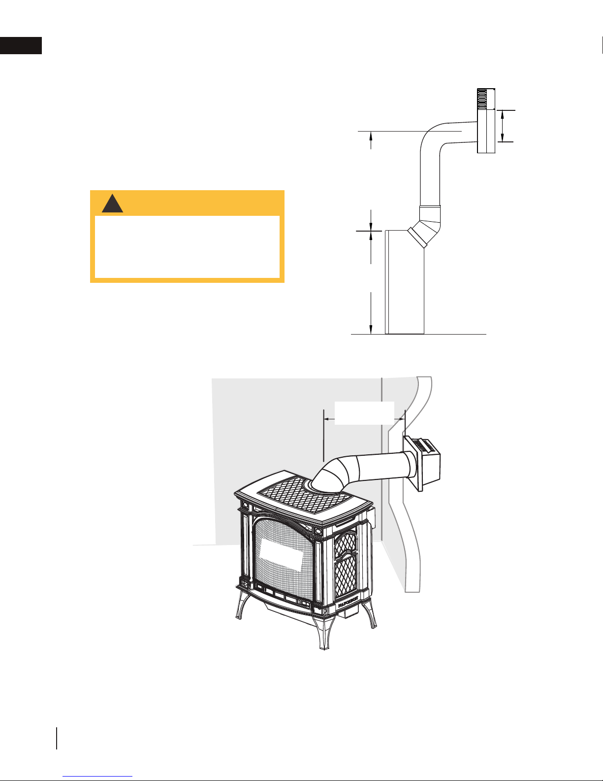
When the appliance is rear vented, a mantel or shelf may be installed above the GDS25-1 at a minimum distance
of 8” (203mm).
installation
EN
L OR
ATERIAL
8” (203mm)
MIN.
12” (305mm)
MAX. MANTEL DEPTH
2” (51mm)
COMBUSTIBLE
NON-COMBUSTIBLE
BRICK
1” (25mm)
0” (0mm) IF NONCOMBUSTIBLE
FINISHING IS
USED SUCH AS
BRICK AND STONE
24 1/2”
(622mm)
2”
(51mm)
W415-2207 / B / 02.05.18
25
Page 26
Retainer
Door
Tab
Front
Bracket
Screws
Front
Front Legs
!
WARNING
GLASS MAY BE HOT, DO NOT TOUCH GLASS UNTIL COOLED.
the appliance.
from the side pieces by
removing the screws from
the brackets located in the
upper inside corners.
remove.
FRONT
SCREWS
BRACKET
3
2
DOOR
RETAINER
FRONT
LEGS
TAB
FRONT
!
WARNING
RISK OF FIRE!
NEVER OBSTRUCT THE FRONT OPENING OF THE APPLIANCE.
REMOVED, CRACKED, BROKEN OR SCRATCHED.
72.4
casting.
WARNING
EN
4.0 finishing
!
• Risk of fi re!
• Never obstruct the front opening of the appliance.
• Do not strike, slam, or scratch. Do not operate appliance with glass removed, cracked, or scratched.
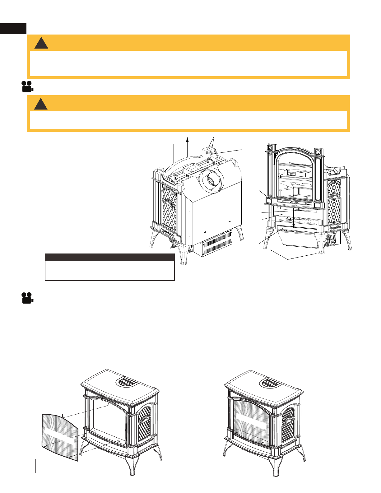
4.1 cast front installation and removal
WARNING
!
• Glass may be hot.
• Do not touch glass until cooled.
A. Remove safety barrier.
B. Lift the top cast piece off of
the appliance.
C. Detach the front cast piece
from the side pieces by
removing the screws from the
brackets located in the upper
inside corners.
D. Slide the front straight up to
remove.
Follow the above steps in reverse in
order to reinstall the cast front. Ensure
that the tabs on the underside of the
front fit behind the front legs.
note:
It is not necessary to remove the cast front in
order to remove the door.
4.2 safety barrier installation and removal
A barrier designed to reduce the risk of burns from the hot viewing glass is provided with the appliance
and shall be installed.
A. Lift the top casting up and remove the safety barrier. Remove and discard plastic.
B. Tilt the top of the safety barrier and hook under the top casting, make sure to hold the safety barrier.
C. Slightly lift the bottom of the safety barrier and push onto theappliance. Careful not to scratch the bottom
casting.
D. Reverse these steps to remove.
SAFETY BARRIER
SAFETY BARRIER
26
W415-2207 / B / 02.05.18
Page 27
LATCHES
DOOR
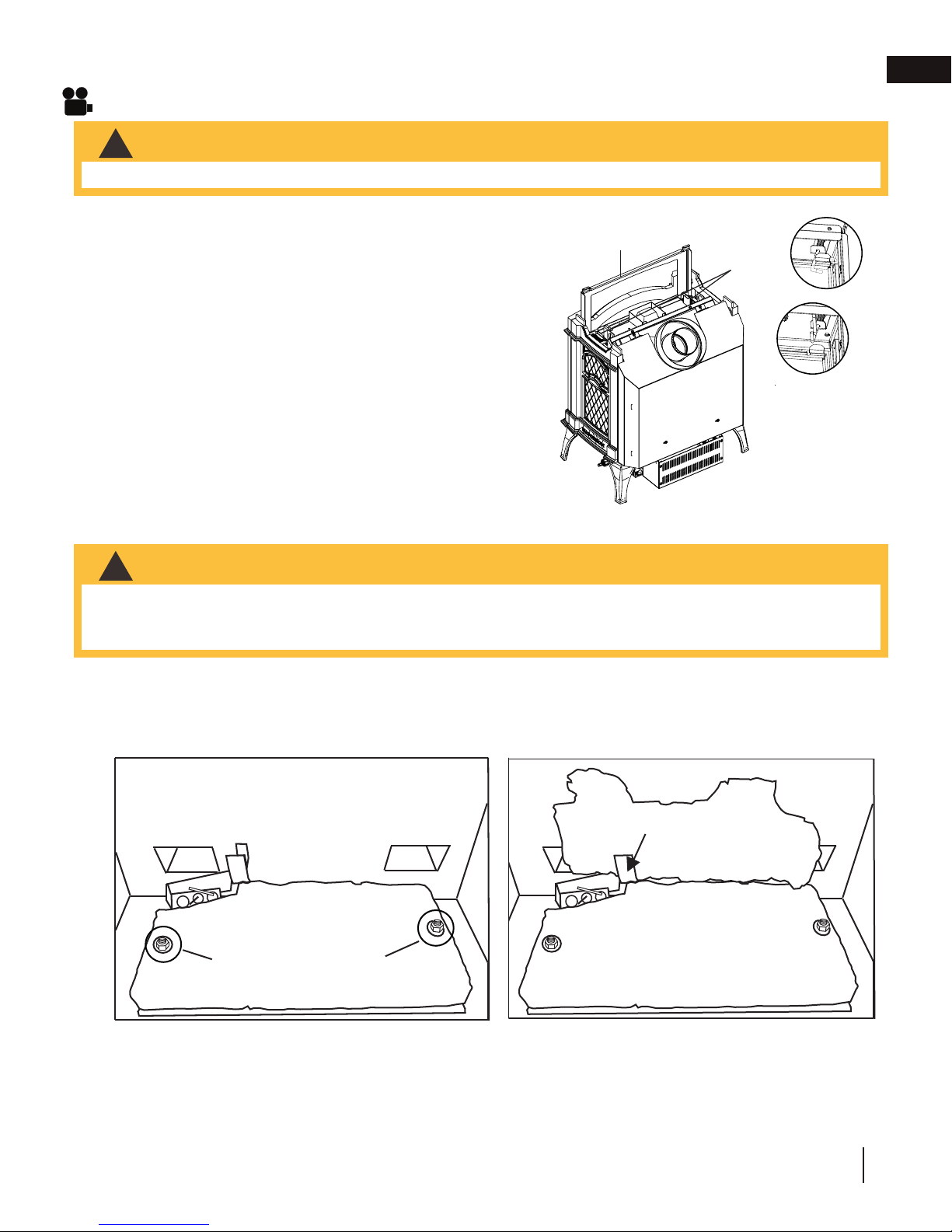
4.3 glass door installation and removal
WARNING
!
• Do not substitute materials.
A. Remove safety barrier.
B. Lift the top cast piece off of the appliance.
C. Pull handle and rotate 90°.
D. Slide the door straight up to remove.
Follow the above steps in reverse in order to reinstall the door.
Ensure that the bottom of the door engages the door retainer
before closing the latches.
finishing
EN
4.4 log placement
WARNING
!
• Logs must be placed in the exact location in appliance. Do not change from the proper log positions, as
appliance may not function properly.
• The logs are fragile and should be handled with care.
It is not necessary to remove the cast front, however, this will make for a more simple log installation.
In order to assemble the log set, the glass door must be removed, see “cast front / glass door installation and
removal” section.
BRACKET
LOG LOCATING SCREWS
A. Place the rear log, as shown, onto the rear log
support brackets. Ensure the cutout on the left
underside of the log, fits over the pilotassembly. Bend the bracket on the left side to help
retain the rear log.
W415-2207 / B / 02.05.18
27
Page 28
MAIN
BURNER
SWITCH
ACCENT
LIGHT
SWITCH
FAN
CONTROL
LOGO
1/2”
1/2”
C. Place the hole in the underside of log #3 onto
the locating screw, on the right side of the
burner. The bottom branch of log #3 sits in
front of, and against, the right end of log #2.
D. Reinstall the glass door & front.
EN
finishing
B. Place the hole in the underside of log #2
onto the locating screw, on the left side of the
burner. The fibre burner is formed to cradle the
centre of the log.
4.5 logo placement
Remove the backing from the logo and position onto the control door as shown.
C. Place the hole in the underside of log #3 onto
the locating screw, on the right side of the
burner. The bottom branch of log #3 sits in
front of, and against, the right end of log #2.
D. Reinstall the glass door & front.
W415-2207 / B / 02.05.18
28
Page 29
5.0 optional blower installation
WARNING
!
• Ensure the appliance is completely cool before starting installation.
• To avoid danger of suffocation, keep the packaging bag away from babies and children. Do not use in
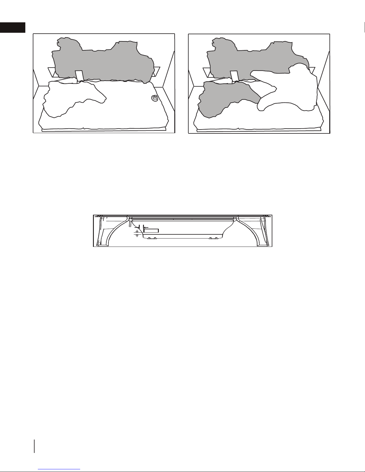
cribs, beds, carriages, or play pens. This bag is not a toy. Knot before throwing away.
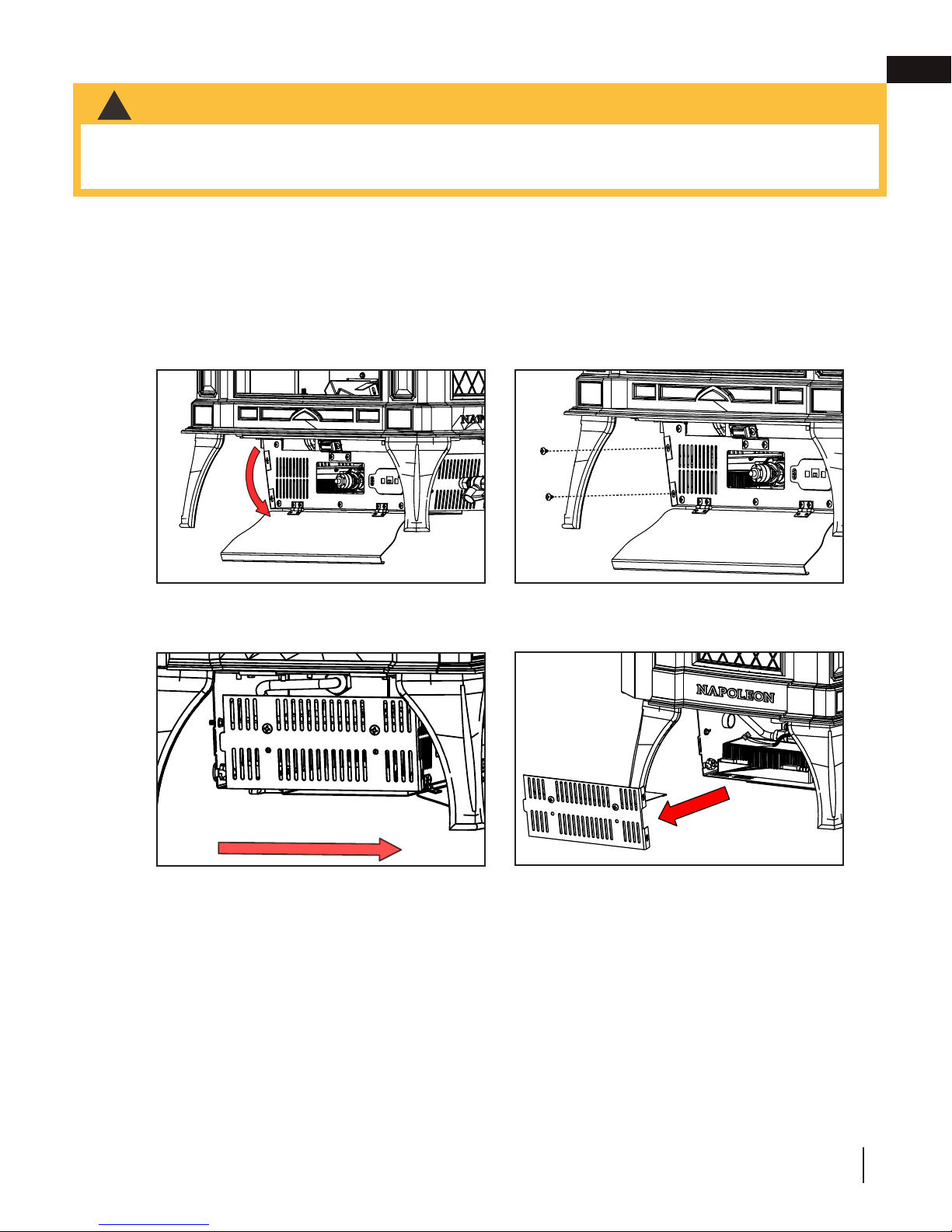
A. Disconnect power supply from the appliance.
B. Open the control door located at the bottom front of the appliance (FIG. 1).
C. Remove the 2 screws holding the left control box cover (FIG. 2).
D. Slide the control box cover forward and remove from the appliance (FIG. 3 and 4).
FIG. 1 FIG. 2
EN
FIG. 3
FIG. 4
W415-2207 / B / 02.05.18
29
Page 30
EN
optional blower installation
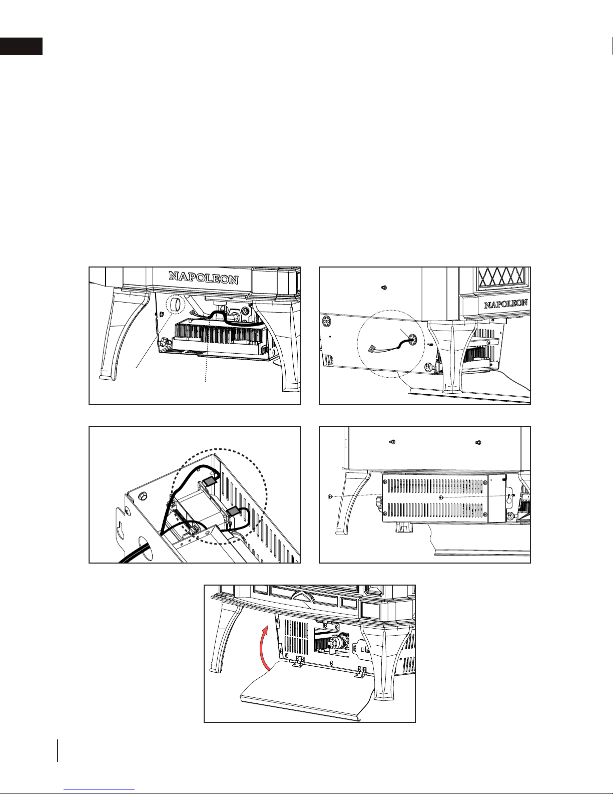
E. Access blower wire leads. Remove 2 insulation connectors from blower wire leads.
F. Route the blower wire through the rear hole of the housing (FIG. 5 and 6).
G. Snap bushing over blower wire and press into rear hole of housing.
H. Place blower housing close to the rear of the appliance. Route wire through hole in blower housing and
connect the spade connectors to blower (FIG. 7).
I. Align the blower to the rear side of the control box and fasten it with 2 screws included with the kit
(FIG. 8).
J. Re-install control box side cover to the control box using the 2 screws previously removed in Step C.
K. Close the control door (FIG. 9).
L. Reconnect power supply to the appliance.
FIG. 5
FIG. 7
FIG. 6
BUSHING
Rear Hole
Wire Harness
FIG. 8
Spade Connectors
FIG. 9
30
W415-2207 / B / 02.05.18
Page 31

6.0 wiring diagram
ELECTRONIC
WARNING
!
• Do not wire 110 volts to the valve or wall switch.
This appliance must be electrically connected and grounded in accordance with local codes. In the absence of
local codes, use the current CSA C22.1 Canadian electrical code in Canada or the ANSI/NFPA national electrical
code in the United States.
BLOWER
OPTIONAL
(POWER CORD)
WIRE HARNESS)
(BLOWER/NIGHT LIGHT
EN
NIGHT
BLOWER
LIGHT
JUMPER
PILOT
IGNITION
ELECTRONIC
VALV E
note:
Jumper is only present when appliance is equipped and operated with remote control.
(RECEIVER)
RESET
BUTTON
WITH RESET BUTTON
BATTERY HOLDER COMPLETE
note:
This appliance is equipped with a three-prong (grounding) plug for protection against shock hazard and should
be connected into a properly grounded circuit. Do not cut or remove the grounding prong from the plug.
W415-2207 / B / 02.05.18
31
Page 32

!
WARNING
D.
EN
7.0 operation
• If you do not follow these instructions exactly, a fi re or explosion may result causing property damage, personal
injury, or loss of life.
• If applicable, always light the pilot whether for the fi rst time or if the gas supply has run out with the glass door
opened or removed.
Ensure that a continuous gas fl ow is at the burner before installing the door. When lit for the fi rst time, the
appliance will emit an odor for a few hours. This is a normal temporary condition caused by the “burn-in” of
paints and lubricants used in the manufacturing process and will not occur again. After extended periods of
non-operation, such as, following a vacation or warm weather season, the appliance may emit a slight odor for a
few hours. This is caused by dust particules in the heat exchanger burning off. In both cases, open a window to
suffi ciently ventilate the room.
FOR YOUR SAFETY READ BEFORE LIGHTING
• Do not turn on if children or other at risk individuals are near the appliance.
• This appliance is equipped with an ignition device which automatically lights the pilot. Do not try to light the
pilot by hand.
• Before operating, smell all around the appliance area for gas and next to the fl oor because some gas is
heavier than air and will settle on the fl oor.
• Do not use this appliance if any part has been under water. Immediately call a qualifi ed service technician
to inspect the appliance and replace any part of the control system and any gas control which has been
underwater.
WHAT TO DO IF YOU SMELL GAS
• Turn off all gas to the appliance.
• Open windows.
• Do not try to light any appliance.
• Do not touch any electric switch; do not use
any phone in your building
• Immediately call your gas supplier from a
neighbour’s phone. Follow the gas supplier’s
instructions.
• If you cannot reach your gas supplier, call
the fi re department.
LIGHTING INSTRUCTIONS
note:
This appliance is equipped with an ignition device which automatically lights the pilot. Do not try to light the
pilot by hand.
A. Stop! Read the above safety information on this label.
B. Remove batteries from the transmitter and set thermostat to lowest setting, if
equipped.
C. Turn off all electrical power to the appliance.
D. Open the glass door, if equipped.
E. Turn the manual shut-off valve clockwise to the “OFF” position. (Shut-off valve is
located on the fl ex connector).
F. Wait fi ve (5) minutes to clear out any gas. If you smell gas including near the
fl oor, STOP! Follow the instructions above in the “WHAT TO DO IF YOU
SMELL GAS” section. If you don’t smell gas; close the glass door and go to
the next step.
G. Turn the manual shut-off valve counter clockwise to the “ON” position.
H. Turn on all electrical power to the appliance and re-install the batteries into the
transmitter. Set thermostat to desired setting, if equipped.
I. Turn on the remote wall switch to the appliance.
J. If the appliance will not operate, follow instructions “TO TURN OFF GAS” and
call your service technician or gas supplier.
TO TURN OFF GAS
A. Set thermostat to lowest setting, if equipped.
B. Turn off the remote wall switch to the appliance.
C. Turn off all electric power to the appliance if service is to be performed.
Turn manual shutoff valve clockwise to the “OFF” positon. Do not force.
add gas knob
add gas valve
32
W415-2207 / B / 02.05.18
Page 33

7.1 general transmitter layout
Transmission
Flame ON
Key Lock
operation
Low battery alarm
Room
Temperature
CPI mode
EN
Blower
note:
Transmitter is optional with this model.
7.2 initializing the transmitter / battery holder for the first time
A. Install the 4 AA batteries into the Proflame 2 battery holder, note the polarity of the batteries and insert as
indicated on the cover (+/-).
B. Ensure the 3 position slider switch is switched to the “REMOTE” position (middle position).
C. Press the reset/programming button, use a small object such as a paper clip in order to reach the button
marked PRG, as shown in the illustration below.
D. The battery holder will beep 3 times to indicate that it’s ready to synchronize with the transmitter.
E. Install the 3 AAA batteries into the transmitter, as shown in the photograph below, then press the ON
button, The battery holder will beep 4 times to indicate that the transmitter’s command is accepted.
note:
The initializing process must be completed within 10 seconds of pressing the reset / program button (PRG).
Light
TRANSMITTER
BATTERY HOLDER
SLIDER SWITCH
RESET/PROGRAM
BUTTON (PRG)
(4) AA Batteries
W415-2207 / B / 02.05.18
33
Page 34

A. Press the ON/OFF key on the transmitter. The transmitter display will show
all active icons on the screen. A single “beep” from the receiver will confi rm
reception of the command.
Blue LCD Display
On / Off Key
Up / Down Arrow Key
Mode Key
Temperature Key
76
°F
OFF
76
°F
ON
°F
ADD TITLE: TEMPERATURE DISPLAY
A. With the system in the off position, press the Temperature Key and the
ADD TITLE: HAND HELD REMOTE OPERATION
Blue LCD Display
On / Off Key
Up / Down Arrow Key
Mode Key
Temperature Key
73 23
76
°F
OFF
76
°F
ON
76
°F
°F °C
Blue LCD Display
On / Off Key
Up / Down Arrow Key
Mode Key
Temperature Key
73 23
76
°F
OFF
76
°F
ON
76
°F
°F °C
Blue LCD Display
On / Off Key
Up / Down Arrow Key
Mode Key
Temperature Key
76
°F
OFF
76
°F
ON
°F
Blue LCD Display
On / Off Key
Up / Down Arrow Key
Mode Key
Temperature Key
73 23
76
°F
OFF
76
°F
ON
76
°F
Blue LCD Display
On / Off Key
Up / Down Arrow Key
Mode Key
Temperature Key
73 23
76
°F
OFF
76
°F
ON
76
°F
°F
°F
°F °C
A. Press the ON/OFF key on the transmitter. The transmitter display will show
all active icons on the screen. A single “beep” from the receiver will confi rm
reception of the command.
Blue LCD Display
On / Off Key
Up / Down Arrow Key
Mode Key
Temperature Key
76
°F
OFF
76
°F
ON
°F
ADD TITLE: TEMPERATURE DISPLAY
A. With the system in the off position, press the Temperature Key and the
mode key at the same time to change from degrees F to C.
B. Look at the LCD screen on the transmitter to verify that a C or F is
visible to the right of the Room Temperature display.
ADD TITLE: HAND HELD REMOTE OPERATION
The remote transmitter can operate as a room thermostat.
The thermostat can be set to a desired temperature to control the comfort level in the
room.
A. Press the thermostat key. The LCD display on the transmitter will show that the
room is on and the set temperature is now displayed.
B. To adjust the set temperature, press the mode key until the desired set
temperature is displayed on the LCD screen of the transmitter.
Blue LCD Display
On / Off Key
Up / Down Arrow Key
Mode Key
Temperature Key
73 23
76
°F
68
Room Temperature
Set Temperature
76
°F
OFF
76
°F
ON
76
°F
76
°F
68
76
°F
Hi
°F
°F
ON
°F °C
ADD TITLE: ROOM THERMOSTAT
ADD TITLE: SMART THERMOSTAT
The Smart Thermostat function adjusts the fl ame height according to the difference between
the set temperature and the actual room temperature. As the room temperature gets closer to
the set point the Smart Function will automatically adjust the fl ame down.
A. Press the thermostat key until the word SMART appears to the right of the temperature
bulb graphic.
B. To adjust the set temperature, press the mode key until the desired set temperature is
displayed on the LCD screen at the transmitter.
Blue LCD Display
On / Off Key
Up / Down Arrow Key
Mode Key
Temperature Key
73 23
76
°F
68
Room Temperature
76
°F
MAX
76
°F
OFF
76
°F
ON
76
°F
76
°F
68
76
°F
Hi
76
°F
OFF
76
°F
ON
SMART
°F °C
The remote control has six (6) fl ame levels. With the system on and the fl ame level at the maximum, press the Down
ADD TITLE: FLAME HEIGHT
Blue LCD Display
On / Off Key
Up / Down Arrow Key
Mode Key
Temperature Key
73 23
76
°F
68
Room Temperature
Set Temperature
76
°F
MAX
76
76
76
76
Flame Off Flame at level 1 Flame at level 5 Flame at “Hi” level 6
76
°F
OFF
76
°F
ON
76
°F
76
°F
68
76
°F
Hi
76
°F
OFF
76
°F
ON
SMART
°F °C
76
°F
OFF
76
°F
ON
76
°F
Blue LCD Display
On / Off Key
Up / Down Arrow Key
Mode Key
Temperature Key
73 23
76
°F
OFF
76
°F
ON
76
°F
°F °C
Blue LCD Display
On / Off Key
Up / Down Arrow Key
Mode Key
Temperature Key
73 23
76
°F
OFF
76
°F
ON
76
°F
°F
°F
°F °C
A. Press the ON/OFF key on the transmitter. The transmitter display will show
all active icons on the screen. A single “beep” from the receiver will confi rm
reception of the command.
Blue LCD Display
On / Off Key
Up / Down Arrow Key
Mode Key
Temperature Key
76
°F
OFF
76
°F
ON
°F
ADD TITLE: TEMPERATURE DISPLAY
A. With the system in the off position, press the Temperature Key and the
mode key at the same time to change from degrees F to C.
B. Look at the LCD screen on the transmitter to verify that a C or F is
visible to the right of the Room Temperature display.
ADD TITLE: HAND HELD REMOTE OPERATION
The remote transmitter can operate as a room thermostat.
The thermostat can be set to a desired temperature to control the comfort level in the
room.
A. Press the thermostat key. The LCD display on the transmitter will show that the
room is on and the set temperature is now displayed.
B. To adjust the set temperature, press the mode key until the desired set
temperature is displayed on the LCD screen of the transmitter.
Blue LCD Display
On / Off Key
Up / Down Arrow Key
Mode Key
Temperature Key
73 23
76
°F
68
Room Temperature
Set Temperature
76
°F
OFF
76
°F
ON
76
°F
76
°F
68
76
°F
Hi
°F
°F
ON
°F °C
ADD TITLE: ROOM THERMOSTAT
ADD TITLE: SMART THERMOSTAT
The Smart Thermostat function adjusts the fl ame height according to the difference between
the set temperature and the actual room temperature. As the room temperature gets closer to
the set point the Smart Function will automatically adjust the fl ame down.
A. Press the thermostat key until the word SMART appears to the right of the temperature
bulb graphic.
B. To adjust the set temperature, press the mode key until the desired set temperature is
displayed on the LCD screen at the transmitter.
Blue LCD Display
On / Off Key
Up / Down Arrow Key
Mode Key
Temperature Key
73 23
76
°F
68
Room Temperature
76
°F
MAX
76
°F
OFF
76
°F
ON
76
°F
76
°F
68
76
°F
Hi
76
°F
OFF
76
°F
ON
SMART
°F °C
The remote control has six (6) fl ame levels. With the system on and the fl ame level at the maximum, press the Down
arrow key once and it will reduce the fl ame height by one step until the fl ame is turned off.
The Up Arrow Key will increase the fl ame height each time it is pressed. If the Up arrow key is pressed while the
system is on but the fl ame is off, the fl ame will come on at the high position. A single “beep” will confi rm reception of
the command.
ADD TITLE: FLAME HEIGHT
Blue LCD Display
On / Off Key
Up / Down Arrow Key
Mode Key
Temperature Key
73 23
76
°F
68
Room Temperature
Set Temperature
76
°F
MAX
76
°F
OFF
76
°F
76
°F
76
°F
Hi
Flame Off Flame at level 1 Flame at level 5 Flame at “Hi” level 6
76
°F
OFF
76
°F
ON
76
°F
76
°F
68
76
°F
Hi
76
°F
OFF
76
°F
ON
SMART
°F °C
If the appliance is equipped with a hot air circulating fan, the speed of the
ADD TITLE: FAN SPEED
76
°F
OFF
76
°F
ON
76
°F
76
76
Blue LCD Display
On / Off Key
Up / Down Arrow Key
Mode Key
Temperature Key
73 23
76
°F
OFF
76
°F
ON
76
°F
°F °C
Blue LCD Display
On / Off Key
Up / Down Arrow Key
Mode Key
Temperature Key
73 23
76
°F
OFF
76
°F
ON
76
°F
°F
°F
°F °C
Your remote system may have a built in timer (in thermostat mode) that enables the blower (if equipped) to cycle
on and off automatically when the burner turns on and off. With the remote control fan speed preset at the
preferred speed, the blower will come on approximately 5 minutes after the main burner comes on and will shut off
approximately 12 minutes after the burner shuts off.
This time delay is designed to maximize the blower distribution of heated air.
If at any time the burner re-ignites before the twelve minutes are over, the fan will continue to run.
ADD TITLE: TIMED BLOWER
ADD TITLE: CHILD PROOF FUNCTION
This function will lock the keys to avoid unsupervised operation.
A. Press the MODE and UP keys at the same time.
B. To de-activate this function, press the MODE and UP keys at the same time.
ADD TITLE: NIGHT LIGHT
The auxiliary function controls the AUX power outlet on the Control Module
which controls the NIGHT LIGHT™.
A. Use the Mode Key to guide you to the AUX icon.
B. Pressing the Up Arrow Key will activate the NIGHT LIGHT™.
C. Pressing the Down Arrow Key will turn the NIGHT LIGHT™ off. A single
“beep” will confi rm the reception of the command.
76
°F
OFF
76
°F
ON
ADD TITLE: Night Light Dimmer Control
76
°F
OFF
76
°F
ON
76
°F
76
°F
68
76
°F
Hi
76
76
single beep will confi rm reception of the command.
Blue LCD Display
On / Off Key
Up / Down Arrow Key
Mode Key
Temperature Key
73 23
76
°F
68
Room Temperature
76
°F
MAX
76
°F
76
°F
76
°F
76
°F
Hi
Flame Off Flame at level 1 Flame at level 5 Flame at “Hi” level 6
76
°F
76
°F
OFF
76
°F
ON
76
°F
76
°F
68
76
°F
Hi
76
°F
OFF
76
°F
76
°F
76
°F
ON
SMART
°F °C
Blue LCD Display
On / Off Key
Up / Down Arrow Key
Mode Key
Temperature Key
73 23
76
°F
68
Room Temperature
76
°F
MAX
76
°F
76
°F
76
°F
76
°F
Hi
Flame Off Flame at level 1 Flame at level 5 Flame at “Hi” level 6
76
°F
76
°F
OFF
76
°F
ON
76
°F
76
°F
68
76
°F
Hi
76
°F
OFF
76
°F
76
°F
IPI
76
°F
CPI
ON
SMART
°F °C
76
°F
76
°F
Hi
76
°F
OFF
76
°F
ON
76
°F
76
°F
68
76
°F
Hi
76
°F
OFF
76
°F
At any time in the sequence, the blower (if equipped) can be manually turned on/off using the remote
control.
note:
Your remote system may have a built in timer (in thermostat mode) that enables the blower (if equipped) to cycle
on and off automatically when the burner turns on and off. With the remote control fan speed preset at the
preferred speed, the blower will come on approximately 5 minutes after the main burner comes on and will shut off
approximately 12 minutes after the burner shuts off.
This time delay is designed to maximize the blower distribution of heated air.
If at any time the burner re-ignites before the twelve minutes are over, the fan will continue to run.
ADD TITLE: TIMED BLOWER
ADD TITLE: CHILD PROOF FUNCTION
This function will lock the keys to avoid unsupervised operation.
A. Press the MODE and UP keys at the same time.
B. To de-activate this function, press the MODE and UP keys at the same time.
ADD TITLE: NIGHT LIGHT
The auxiliary function controls the AUX power outlet on the Control Module
which controls the NIGHT LIGHT™.
A. Use the Mode Key to guide you to the AUX icon.
B. Pressing the Up Arrow Key will activate the NIGHT LIGHT™.
C. Pressing the Down Arrow Key will turn the NIGHT LIGHT™ off. A single
“beep” will confi rm the reception of the command.
76
°F
OFF
76
°F
ON
ADD TITLE: Night Light Dimmer Control
76
°F
OFF
76
°F
ON
76
°F
76
°F
68
76
°F
Hi
76
°F
OFF
76
°F
The auxiliary function controls the Night Light
TM
with dimmable control.
A. Use the Mode Key to guide you to the Night Light icon.
B. The intensity of the output can be adjusted through 6 levels.
Use the UP/DOWN arrow keys to adjust the output level. A
single beep will confi rm reception of the command.
ADD TITLE: CONTINUOUS PILOT / INTERMITTENT PILOT (CPI / IPI) SELECTION
A. When the transmitter is in the “OFF” position, use the Mode Key to guide
Blue LCD Display
On / Off Key
Up / Down Arrow Key
Mode Key
Temperature Key
73 23
76
°F
68
Room Temperature
76
°F
MAX
76
°F
76
°F
76
°F
76
°F
Hi
Flame Off Flame at level 1 Flame at level 5 Flame at “Hi” level 6
76
°F
76
°F
OFF
76
°F
ON
76
°F
76
°F
68
76
°F
Hi
76
°F
OFF
76
°F
76
°F
76
°F
ON
SMART
°F °C
Blue LCD Display
On / Off Key
Up / Down Arrow Key
Mode Key
Temperature Key
73 23
76
°F
68
Room Temperature
76
°F
MAX
76
°F
76
°F
76
°F
76
°F
Hi
Flame Off Flame at level 1 Flame at level 5 Flame at “Hi” level 6
76
°F
76
°F
OFF
76
°F
ON
76
°F
76
°F
68
76
°F
Hi
76
°F
OFF
76
°F
76
°F
IPI
76
°F
CPI
ON
SMART
°F °C
76
°F
76
°F
ON
76
°F
76
°F
ON
76
°F
76
°F
Hi
76
°F
OFF
76
°F
ON
76
°F
76
°F
68
76
°F
Hi
76
°F
OFF
76
°F
76
76
At any time in the sequence, the blower (if equipped) can be manually turned on/off using the remote
control.
note:
EN
operation
7.3 temperature display
7.4 flame height
7.5 blower speed
7.6 night light dimmer control
7.7 continuous pilot / intermittent pilot (CPI / IPI) selection
34
mode key at the same time to change from degrees F to C.
B. Look at the LCD screen on the transmitter to verify that a C or F is
visible to the right of the Room Temperature display.
arrow key once and it will reduce the fl ame height by one step until the fl ame is turned off.
The Up Arrow Key will increase the fl ame height each time it is pressed. If the Up arrow key is pressed while the
system is on but the fl ame is off, the fl ame will come on at the high position. A single “beep” will confi rm reception of
the command.
°F
°F
OFF
fan can be controlled by the remote system. The fan speed can be adjusted
through six (6) speeds.
A. Use the mode key to guide you to the fan control icon.
B. Use the mode key to turn on/off or adjust the fan speed. A single
“beep” will confi rm reception of the command.
note:
When the desired blower speed is selected, the blower will automatically come on 5 minutes after the main
burner has been turned on and remain on twelve minutes after it has been turned off.
W415-2207 / B / 02.05.18
The auxiliary function controls the Night Light
A. Use the Mode Key to guide you to the Night Light icon.
B. The intensity of the output can be adjusted through 6 levels.
Use the UP/DOWN arrow keys to adjust the output level. A
you to the CPI mode icon.
B. Press the UP/DOWN to switch between IPI and CPI modes. A single BEEP
will confi rm reception of the command.
note:
If the appliance is equipped with a CPI/IPI toggle switch, set the CPI/IPI to CPI
position to enable remote CPI operation. If the switch is set to IPI then it will
only work in IPI regardless of what is set on the remote control handset.
TM
with dimmable control.
68
OFF
IPI
°F °C
°F
°F
°F
°F
CPI
°F
Hi
°F
Hi
°F
°F
Page 35

Your remote system may have a built in timer (in thermostat mode) that enables the blower (if equipped) to cycle
on and off automatically when the burner turns on and off. With the remote control fan speed preset at the
preferred speed, the blower will come on approximately 5 minutes after the main burner comes on and will shut off
approximately 12 minutes after the burner shuts off.
This time delay is designed to maximize the blower distribution of heated air.
If at any time the burner re-ignites before the twelve minutes are over, the fan will continue to run.
ADD TITLE: TIMED BLOWER
ADD TITLE: CHILD PROOF FUNCTION
76
°F
OFF
76
°F
ON
76
°F
Blue LCD Display
On / Off Key
Up / Down Arrow Key
Mode Key
Temperature Key
73 23
76
°F
68
Room Temperature
76
°F
MAX
76
°F
76
°F
76
°F
76
°F
Hi
Flame Off Flame at level 1 Flame at level 5 Flame at “Hi” level 6
76
76
°F
OFF
76
°F
ON
76
°F
76
°F
68
76
°F
Hi
76
°F
OFF
76
°F
76
°F
76
°F
ON
SMART
°F °C
Blue LCD Display
On / Off Key
Up / Down Arrow Key
Mode Key
Temperature Key
73 23
76
°F
68
Room Temperature
76
°F
MAX
76
°F
76
°F
76
°F
76
°F
Hi
Flame Off Flame at level 1 Flame at level 5 Flame at “Hi” level 6
76
°F
76
°F
OFF
76
°F
ON
76
°F
76
°F
68
76
°F
Hi
76
°F
OFF
76
°F
76
°F
IPI
76
°F
CPI
ON
SMART
°F °C
76
°F
OFF
76
°F
ON
76
°F
76
°F
68
76
°F
Hi
At any time in the sequence, the blower (if equipped) can be manually turned on/off using the remote
control.
note:
Your remote system may have a built in timer (in thermostat mode) that enables the blower (if equipped) to cycle
on and off automatically when the burner turns on and off. With the remote control fan speed preset at the
preferred speed, the blower will come on approximately 5 minutes after the main burner comes on and will shut off
approximately 12 minutes after the burner shuts off.
This time delay is designed to maximize the blower distribution of heated air.
If at any time the burner re-ignites before the twelve minutes are over, the fan will continue to run.
ADD TITLE: TIMED BLOWER
ADD TITLE: CHILD PROOF FUNCTION
This function will lock the keys to avoid unsupervised operation.
A. Press the MODE and UP keys at the same time.
B. To de-activate this function, press the MODE and UP keys at the same time.
ADD TITLE: NIGHT LIGHT
The auxiliary function controls the AUX power outlet on the Control Module
which controls the NIGHT LIGHT™.
A. Use the Mode Key to guide you to the AUX icon.
B. Pressing the Up Arrow Key will activate the NIGHT LIGHT™.
C. Pressing the Down Arrow Key will turn the NIGHT LIGHT™ off. A single
“beep” will confi rm the reception of the command.
76
°F
OFF
76
°F
ON
The life span of the remote batteries depends on various factors: quality of the batteries, the
position slider switch on the receiver to the “ON” position. This will bypass the remote control feature and the appliance
main burner will come on if the gas valve is in the “ON” position.
ADD TITLE: LOW BATTERY / MANUAL BYPASS
ADD TITLE: Night Light Dimmer Control
76
°F
OFF
76
°F
ON
76
°F
76
°F
68
76
°F
Hi
76
°F
OFF
76
°F
The auxiliary function controls the Night Light
TM
with dimmable control.
A. Use the Mode Key to guide you to the Night Light icon.
B. The intensity of the output can be adjusted through 6 levels.
Use the UP/DOWN arrow keys to adjust the output level. A
single beep will confi rm reception of the command.
ADD TITLE: CONTINUOUS PILOT / INTERMITTENT PILOT (CPI / IPI) SELECTION
A. When the transmitter is in the “OFF” position, use the Mode Key to guide
you to the CPI mode icon.
B. Press the UP/DOWN to switch between IPI and CPI modes. A single BEEP
will confi rm reception of the command.
Blue LCD Display
On / Off Key
Up / Down Arrow Key
Mode Key
Temperature Key
73 23
76
°F
68
Room Temperature
76
°F
MAX
76
°F
76
°F
76
°F
76
°F
Hi
Flame Off Flame at level 1 Flame at level 5 Flame at “Hi” level 6
76
°F
76
°F
OFF
76
°F
ON
76
°F
76
°F
68
76
°F
Hi
76
°F
OFF
76
°F
76
°F
76
°F
ON
SMART
°F °C
Blue LCD Display
On / Off Key
Up / Down Arrow Key
Mode Key
Temperature Key
73 23
76
°F
68
Room Temperature
76
°F
MAX
76
°F
76
°F
76
°F
76
°F
Hi
Flame Off Flame at level 1 Flame at level 5 Flame at “Hi” level 6
76
°F
76
°F
OFF
76
°F
ON
76
°F
76
°F
68
76
°F
Hi
76
°F
OFF
76
°F
76
°F
IPI
76
°F
CPI
ON
SMART
°F °C
76
°F
76
°F
ON
76
76
°F
76
°F
ON
76
°F
76
°F
76
°F
Hi
76
°F
OFF
76
°F
ON
76
°F
76
°F
68
76
°F
Hi
76
°F
OFF
76
°F
76
°F
IPI
76
°F
CPI
At any time in the sequence, the blower (if equipped) can be manually turned on/off using the remote
control.
note:
If the appliance is equipped with a CPI/IPI toggle switch, set the CPI/IPI to CPI
position to enable remote CPI operation. If the switch is set to IPI then it will
only work in IPI regardless of what is set on the remote control handset.
note:
7.8 key lock
This function will lock the keys to avoid unsupervised operation.
A. Press the MODE and UP keys at the same time.
B. To de-activate this function, press the MODE and UP keys at the same time.
7.9 low battery / manual bypass
operation
°F
EN
number of ignitions, etc.
When the transmitter batteries are low, a Battery Icon will appear on the LCD display before all
battery power is lost. When the batteries are replaced this icon will disappear.
When the receiver batteries are low, no “beep” will be emitted from the receiver when it
receives an ON/OFF command. This in an alert for the receiver that there’s low battery. When
the batteries are replaced the “beep” will be emitted from the receiver when the ON/OFF key is pressed.
If the batteries of the receiver or transmitter are low, the appliance can be turned on manually by sliding the three
W415-2207 / B / 02.05.18
°F
35
Page 36

This appliance has an air shutter that has been factory set open according to
note:
EN
8.0 adjustment
8.1 restricting vertical vents
Vertical installations may display a very active flame. Loosen the two screws and slide the restrictor plate blocking the
exhaust path. This reduces the velocity of the exhaust gases, slowing down the flame pattern and creating a more
traditional flame appearance. For vertical vents greater than 15 ft (5m), this restrictor must be fully closed.
RESTRICTOR SHOWN IN A
FULLY OPEN POSITION
8.2 venturi adjustment
the chart below:
Regardless of venturi orientation, closing the air shutter will cause a more
yellow flame, but can lead to carbonization. Opening the air shutter will cause
a more blue flame, but can cause flame lifting from the burner ports. The flame
may not appear yellow immediately; allow 15 to 30 minutes for the final flame
colour to be established.
AIR SHUTTER ADJUSTMENT MUST ONLY BE DONE BY A QUALIFIED
INSTALLER!
It is important that the orifice is securely inserted into the venturi.
Remove the 2 screws securing the burner. Air shutters have been factory
set open according to the Venturi Adjustment Chart. These settings are for
(maximum) horizontal termination. Adjustment may be required depending
on fuel type, vent configuration and altitude. After making adjustments
replace the burner ensuring that the venturi tube
fits over the orifice and replace the screws.
RESTRICTOR SHOWN IN A
FULLY CLOSED POSITION
VENTURI
BURNER
AIR
SHUTTER
OPENING
ORIFICE
VENTURI ADJUSTMENT CHART
FUEL GDS25-1
NG 5/16” (8mm)
P 7/16” (11mm)
8.3 pilot burner adjustment
Adjust the pilot screw to provide properly sized fl ame. Turn in a clockwise direction to reduce the gas fl ow.
Check Pressure Readings:
Inlet pressure can be checked by turning screw (A) counterclockwise 2 or 3 turns and then placing pressure gauge tubing
over the test point. Gauge should read as described on the chart
below. Check pressure with main burner operating on “HI”.
Outlet pressure can be checked the same as above using screw
(B). Gauge should read as described on the chart below. Check
36
pressure with main burner operating on “HI”.
After taking pressure readings, be sure to turn screws
clockwise fi rmly to reseal. Do not overtorque.
Leak test with a soap and water solution.
W415-2207 / B / 02.05.18
A
B
INSERT PILOT ASSEMBLY
PILOT SCREW
Page 37

It’s important to periodically perform a visual check of
ADD IMAGE
Adjust the pilot screw to provide properly sized fl ame. Turn in a clockwise direction to reduce the gas fl ow.
Check Pressure Readings:
Inlet pressure can be checked by turning screw (A) counter-
clockwise 2 or 3 turns and then placing pressure gauge tubing
over the test point. Gauge should read as described on the chart
below. Check pressure with main burner operating on “HI”.
Outlet pressure can be checked the same as above using screw
(B). Gauge should read as described on the chart below. Check
pressure with main burner operating on “HI”.
After taking pressure readings, be sure to turn screws
clockwise fi rmly to reseal. Do not overtorque.
Leak test with a soap and water solution.
INSERT PILOT ASSEMBLY
*Maximum inlet pressure not to exceed 13”
adjustment
Prior to pilot adjustment, ensure that the pilot assembly has not been painted. If overspray or painting of
the pilot assembly has occurred remove the paint from the pilot assembly, or replace. Fine emery cloth or a
synthetic scrub pad (such as Scotch-Brite™) can be used to remove the paint from the pilot hood, electrode
and fl ame sensor.
EN
Pressure Natural Gas
(inches)
Inlet
Outlet
*7”
(minimum 4.5”)
3.5” 8.7mb 10” 24.9mb
8.4 flame characteristics
the pilot and burner flames. Compare them to the
illustration provided. If any flames appear abnormal,
call a service person.
Natural Gas
(millibars)
17.4mb
(minimum 11.2mb)
SPARK MODULE
Propane
(inches)
13”
(minimum 11”)
FLAME
SENSOR
Propane
(millibars)
32.4mb
(minimum 27.4mb)
PILOT
BURNER
FLAME MUST ENVELOP
UPPER 3/8” (9.5mm) TO
1/2” (12.7mm) OF FLAME
SENSOR
W415-2207 / B / 02.05.18
37
Page 38

WARNING
EN
9.0 maintenance
!
• Turn off the gas and electrical power before servicing the appliance.
• Appliance may be hot. Do not service until appliance has cooled.
• Do not use abrasive cleaners on glass.
• Do not paint the pilot assembly.
This appliance and its venting system should be inspected before use and at least annually by a qualifi ed
service person. The following suggested checks should be performed by a qualifi ed technician. The appliance
area must be kept clear and free of combustible materials, gasoline, or other fl ammable vapors and liquids.
The fl ow of combustion and ventilation air must not be obstructed.
note:
Caution: Label all wires prior to disconnection when servicing controls. Wiring errors can cause improper and
dangerous operation. Verify proper operation after servicing.
1. In order to properly clean the burner and pilot assembly, remove the logs, rocks and/or glass to ex-
pose both assemblies.
2. Keep the control compartment, media, burner, air shutter opening and the area surrounding the appli-
ance clean by vacuuming or brushing, at least once a year.
3. Check to see that all burner ports are burning. Clean out any of the ports which may not be burning
or are not burning properly.
4. Check to see that the pilot fl ame is large enough to engulf the fl ame sensor and/or thermocouple /
thermopile as well as it reaches the burner.
5. If your appliance is equipped with a safety barrier, cleaning may be necessary due to excessive lint /
dust from carpeting, pets, etc. simply vacuum using the brush attachment.
6. If your appliance is equipped with relief doors, ensure the system performs effectively. Check that the
gasket is not worn or damaged. Replace if necessary.
7. Replace the cleaned logs, rocks or glass. Failure to properly position the media may cause carboning
which can be distributed in the surrounding living area, inside the fi rebox and on exterior surfaces surrounding vent termination.
8. Check to see that the main burner ignites completely on all ports when turned on. A 5 to 10 second
total light-up period is satisfactory. If ignition takes longer, consult your local authorized dealer / distributor.
9. Visually inspect the appliance for carbon build up. Using a small whisk or brush, brush off the carbon
and vacuum up or sweep into garbage.
10. This step is not applicable for Vent Free appliances: Check to see that the appliance is vent-
ing correctly. Ensure chimney system is safe and unobstructed. (If for any reason the vent air intake
system is disassembled, re-install and re-seal per the instructions provided for the initial installation).
38
W415-2207 / B / 02.05.18
Page 39

WARNING
maintenance
9.1 annual maintenance
!
• Annual maintenance should be performed by a qualifi ed service technician
• The fi rebox becomes very hot during operation. Let the appliance cool completely or wear heat resistant
gloves before conducting service.
• Never vacuum hot embers.
• Do not paint the pilot assembly
• This appliance will require maintenance which should be planned on an annual basis.
• Service should include cleaning, battery replacement, venting inspection and inspection of the burner,
media, and fi rebox. Refer to the door removal section and remove the door as instructed.
• Carefully remove media if necessary (logs, glass, brick panels, etc.).
• Using a vacuum with soft brush attachment, gently remove any dirt, debris, or carbon build up from the
logs, fi rebox, and burner. For glass media, follow the installation instructions for pre-cleaning.
• Gently remove any build-up on the pilot assembly including thermopile, thermocouple, fl ame sensor, and
igniter (if equipped).
note:
Clean fl ame sensor using a fi ne emery cloth or a synthetic scrub pad (such as Scotch-Brite™) to remove any
oxides. Clean the pilot assembly using a vacuum with a soft brush attachment. It is important that the pilot
assembly is not painted.
EN
• Inspect all accessible gaskets and replace as required.
• If equipped with a blower, access the blower and clean using a soft brush and vacuum.
• Re-assemble the various components in reverse order.
• Inspect the relief system. The appliance relieves through the main glass door or through the fl aps on the
fi rebox top. Ensure they open freely, and close sealed.
• Check the gas control valve pilot and Hi / Lo knobs move freely, if equipped. Replace if any stiffness in
movement is experienced.
• Check for gas leaks on all gas connections up and downstream from the gas valve including pilot tube
connections.
W415-2207 / B / 02.05.18
39
Page 40

GASKET
GLASS LENS
GASKET
SHEILD
RAIL
WIRE NUT
COVER PLATE
RELIEF
DOOR
35
EN
37.1C
35
EN
EN
maintenance
9.2 night light replacement
This appliance comes equipped with our “Night Light”.
If in the event the lamp or lens needs to be replaced, follow these instructions.
Disconnect the two wire leads at the wire nut. Remove the four screws
securing the accent light assembly from the relief door. Disassemble the
light and the lamp now can be accessed
WIRE NUT
note:
Do not handle the lamp (bulb) with bare fingers. Protect with a clean, dry
cloth.
The lamp will pull straight out of the socket. Replace with Wolf Steel
parts only, as lamp and lens are special “high temperature” products.
When re-installing, ensure integrity of gasket seal.
THE FIREBOX MUST BE SEALED.
RAIL
When re-assembling the light assembly, care must be
taken with all gaskets.
“Light Leakage” from above the cast doors may be noticed. The holes in the lamp housing are
necessary for ventilation and must not be covered.
9.3 pilot injector and orifice replacement
WARNING
!
• Always light the pilot whether for the first time or if the gas supply has run out with the glass door open or
removed.
This must be carried out by an AUTHORIZED REPRESENTATIVE OF WOLF STEEL
LTD. or a QUALIFIED GAS INSTALLER in accordance with local codes or in the
absence of local codes with the requirements of the provincial / state authorities having
jurisdiction and in accordance with the requirements of the CAN1-B149 Installation Code
in Canada and the ANSI Z223.1 National Fuel Gas Code in the United States.
SHIELD
SHEILD
COVER PLATE
GASKET
GLASS LENS
GASKET
RELIEF
DOOR
RAIL
40
A. Turn off the electrical and gas supply to the appliance.
B. Remove the cast front, glass viewing door and log set.
C. Remove the 2 securing screws. Slide the burner assembly to the right and lift out.
D. Using a deep socket wrench, remove the main burner orifice. A back-up wrench
must be used on themanifold, located below the housing to ensure that the
aluminum tubing does not twist or kink. Replace the correct burner orifice using
pipe thread compound.
E. Loosen nut and replace with appropriate injector
F. Reinstall the burner ensuring that the Venturi tube fits over the orifice.
G. Turn on the gas supply and check for gas leaks by brushing on a soap and water
solution. Do not use open flame.
H. Replace the log set. Then light the pilot and main burner to ensure that the gas
lines have been purged.
I. Replace the glass viewing door and cast front. Turn on the electrical supply to the
appliance.
W415-2207 / B / 02.05.18
ORIFICE
LOCATION
BURNER
ASSEMBLY
Page 41

!
WARNING
If the appliance is equipped with plated parts, you must clean fi ngerprints or other marks from the plated surfaces
9.4 care of glass
• Do not clean glass when hot! Do not use abrasive cleaners to clean glass.
Buff lightly with a clean dry soft cloth to remove accumulated dust or fi ngerprints. Clean both sides of the glass
after the fi rst 10 hours of operation with an ammonia-free glass cleaner.
note:
Vinegar-based glass cleaners have demonstrated an ability to provide a clean, streak free glass surface.
Thereafter, clean as required. If the glass is not kept clean permanent discoloration and / or blemishes may
result. Contact you local authorized dealer / distributor for complete cleaning instructions.
Razor blades, steel wool, or other metallic objects must not be used on both surfaces of the glass. Doing so
can remove a thin layer of metal from the razor blades, steel wool, or other metallic objects that may then be
deposited onto the coating. This can result in a discoloured stain or scratch-like mark. More importantly, this can
scratch the glass surface, thereby reducing its strength.
Do not operate the appliance with broken glass, as leakage of fl ue gases may result.
Contact your local authorized dealer / distributor for complete cleaning instructions.
If the glass should ever crack or break while the fi re is burning, do not open the door until the fi re is out. Do not
operate the appliance until the glass has been replaced. Contact you local authorized dealer / distributor for
replacement parts. DO NOT SUBSTITUTE MATERIALS.
This appliance is factory equipped with 5mm ceramic glass. Use only replacement parts as supplied by the
appliance manufacturer. DO NOT SUBSTITUTE MATERIALS.
maintenance
EN
9.5 care of plated parts
before operating the appliance for the fi rst time. Use an ammonia-free or vinegar-based cleaner and a towel
to clean. If not cleaned properly before operating for the fi rst time, the marks can cause permanent blemishes
on the plating. After the plating is cured, the fi ngerprints and oils will not affect the fi nish and little maintenance
is required, just wipe clean as needed. Prolonged high temperature burning with the door ajar may cause
discolouration on plated parts.
note:
The protective wrap on plated parts is best removed when the assembly is at room temperature but this can
be improved if the assembly is warmed (i.e. using a hair dryer or similar heat source).
W415-2207 / B / 02.05.18
41
Page 42

WARNING
Parts identifi ed as ‘SO’ are special order and can take up to 90 days for delivery
EN
10.0 replacements
!
• Failure to position the parts in accordance with this manual or failure to use only parts specifi cally approved
with this appliance may result in property damage or personal injury.
Contact your dealer for questions concerning prices and policies on replacement parts. Normally, all parts can
be ordered through your Authorized dealer / distributor.
For warranty replacement parts, a photocopy of the original invoice will be required to honour the
claim.
When ordering replacement parts always give the following information:
• Model & Serial Number of appliance
• Installation date of appliance
• Part number
• Description of part
• Finish
Parts, part numbers, and availability are subject to change without notice.
Parts identifi ed as stocked will be delivered within 2 to 5 business days for most delivery
destinations.
Parts not identifi ed as stocked will be delivered within a 2 to 4 week period, for most cases.
42
W415-2207 / B / 02.05.18
Page 43

Items may not appear exactly as illustrated.
Safety Barrier
4
5
10
11
14
19
Part No.
Ref. No.
W135-0254
W135-0249
W135-0250
GL-651
W385-2010
W135-0580
W010-3295
W010-1379
1115161819
W010-4177
W350-0655
141213 Front casting
Safety barrier
Door assembly
Rear log (GL-651)
Left log (GL-651)
Right log (GL-651)
Top casting
X2
Yes
Yes
Yes
Yes
Yes
17
replacements
Yes
Yes
Yes
EN
10.1 overview
Yes
Yes
3
1
2
W415-2207 / B / 02.05.18
43
Page 44

Items may not appear exactly as illustrated.
Description
Ref. No.
Description
12
W456-0043
13
Stocked
11
Battery housing
151516
W725-0046
Gas valve shut-off
14
Valve (P)
17
18
Pro 2 wire harness
W750-0268
W660-0126-SER
Pro 2 transmitter
9
W432-0078
3/8" manifold
19
3
5
8
10
111412
15
16
19
W750-0411
Valve (NG)
W707-0019
Transformer
W456-0054
Yes
Yes
Yes
Yes
Yes
Yes
Yes
Yes
Yes
Yes
Yes
Yes
Yes
Yes
Yes
10
Yes
W456-0055
Burner orifice #44 (NG) (high altitude)
W456-0044
Yes
Yes
EN
0
7
67°
Yes
44
10.2 valve train assembly
W415-2207 / B / 02.05.18
Page 45

5
5
1
3
4
Ref. No.
1
4
GDSLL-KT
Leg leveling / stove securing kit
accessories
A stone inset can be cut to enhance the cast
top and to match the room décor. A template
is available to be downloaded from the
porduct website. Use this to cut the stone
slab to size so that it will fit into the cast
recess.
EN
11.0 accessories
W415-2207 / B / 02.05.18
45
Page 46

WARNING
EN
12.0 troubleshooting
!
• Always light the pilot whether for the fi rst time or if the gas supply has run out, with the glass door open or
removed.
• Turn off gas and electrical power before servicing the appliance.
• Appliance may be hot. Do not service until appliance has cooled.
• Do not use abrasive cleaners
symptom problem test solution
Main burner fl ame is a
blue, lazy, transparent
fl ame.
(This is not applicable
in outdoor appliances)
Flames are consistently
too large or too small.
Carboning occurs.
INSERT
Blockage in vent. - Remove blockage. In really cold conditions, ice buildup may occur
Incorrect installation. - Refer to “venting” section to ensure correct installation.
Appliance is over-fi red or underfi red.
on the terminal and should be removed as required. (To minimize this
from reoccuring, the vent lengths that pass through unheated spaces
(attics, garages, crawl spaces) be wrapped with an insulated mylar
sleeve).
- Check pressure readings:
Inlet pressure can be checked by turning screw (A) counter-clockwise 2 or 3 turns and then placing pressure gauge tubing over the
test point. Gauge should read as described on the chart below.
Check that main burner is operating on ‘HI’. Outlet pressure can be
checked the same as above using screw (B). Gauge should read as
described on the chart below. Check that main burner is operating
on ‘HI’. After taking pressure readings, be sure to turn screws
clockwise fi rmly to reseal. DO NOT OVER TORQUE.
Leak test with a soap and water solution.
PHOTO
OF VALVE
HERE
Pressure Natural Gas
Inlet
Outlet
(inches)
*7”
(minimum 4.5”)
3.5” 8.7mb 10” 24.9mb
Natural Gas
(millibars)
17.4mb
(minimum 11.2mb)
*Maximum inlet pressure not to exceed 13”
Propane
(inches)
13”
(minimum 11”)
Propane
(millibars)
32.4mb
(minimum 27.4mb)
46
Air shutter improperly adjusted.
Carbon is being
deposited on glass,
logs, rocks, media, or
combustion chamber
surfaces.
White / grey fi lm forms. Sulphur from fuel is being depos-
Exhaust fumes smelled
in room, headaches.
W415-2207 / B / 02.05.18
Air shutter is blocked. - Ensure air shutter opening is free of lint or other obstructions.
Flame is impinging on the glass,
logs, rocks, media or combustion chamber.
ited on glass, logs, or combustion chamber surfaces.
Appliance is spilling.
(This is not applicable in outdoor
appliances).
- Return air shutter to specifi ed opening, see “venturi adjustments”
section in the installation manual.
- Ensure the media is positioned correctly in the appliance.
- Open air shutter to increase the primary air.
- Check the input rate: check the manifold pressure and orifi ce size as
specifi ed by the rating plate.
- Ensure door gaskets are not broken or missing and the seal is tight.
- Ensure vent liners are free of holes and well sealed at all joints.
- Check that minimum rise per foot (meters) has been adhered to for
any horizontal venting.
- Clean the glass with a recommended gas fi replace glass cleaner. DO
NOT CLEAN GLASS WHEN HOT.
- If deposits are not cleaned off regularly, the glass may become
permanently marked.
- Check door seal.
- Check for exhaust damage.
- Check that venting is installed correctly.
- Room is in negative pressure; increase fresh air supply.
Page 47

Exhaust fumes smelled
in room, headaches.
Appliance is spilling.
(This is not applicable in outdoor
appliances).
- Check door seal.
- Check for exhaust damage.
- Check that venting is installed correctly.
- Room is in negative pressure; increase fresh air supply.
Valve wiring is damaged. - Replace valve.
symptom problem test solution
Pilot will not light. Makes
noise with no spark at
pilot burner.
Pilot sparks but will
not light.
Burner continues to
spark and pilot lights
but main burner
does not light.
Remote wall switch
is in “off” position;
burner comes on.
Remote and / or
receiver is not
functioning properly.
Wiring: short, loose, or damaged
connections
(poor fl ame rectifi cation).
No signal from remote with no
pilot ignition.
Poor grounding. - Verify the valve and pilot assembly is properly grounded
Improper switch wiring.
Dirty, painted, or damaged pilot
and/or dirty sensor rod.
- Verify the thermocouple/sensor is clean and the wiring is undamaged.
- Verify the interrupter block is not damaged or too tight. Verify
connections from pilot assembly are tight; also verify the connections
are not grounding out to any metal. (Remember, the fl ame carries the
rectifi cation current, not the gas. If fl ame lifts from pilot hood, the circuit
is broken. A wrong orifi ce or too high of an inlet pressure can cause the
pilot fl ame to lift)*. The sensor rod may need cleaning.
- Reprogram receiver code.
- Replace receiver.
- Troubleshoot the system with the simplest on/off switch.
- Clean sensor rod with a green Scotch-Brite™ pad to remove any
contamination that may have accumulated. Verify continuity with
multimeter with ohms set at the lowest range.
Gas supply. - Verify that the incoming gas line ball valve is “open”.
- Verify that the inlet pressure reading is within acceptable
limits, inlet pressures must not exceed 14” W.C. (34.9mb).
Out of propane gas. - Fill the tank.
Pilot supply line may contain
air.
- Repeat ignition process several times or purge the pilot
supply line.
Incorrect wiring / grounding. - Ensure correct polarity of wiring of thermocouple (if
equipped).
- Verify pilot assembly/valve are properly grounded.
Receiver (if equipped). - Reset program: hold reset button on receiver and wait for 2
beeps. Release after second beep. Press small fl ame button
on remote within 20 seconds, you will hear an additional
beep (this signals a successful reset).
- Replace receiver.
Valve. - Check valve and replace if necessary (Do not to overtighten
thermocouple).
Short or loose connection in
sensor rod.
- Verify all connections. Verify the connections from the pilot
assembly are tight. Also, verify these connections are not
grounding out to any metal.
Dirty, painted, or damaged
pilot assembly components.
- Clean using a green Scotch-Brite™ pad to remove any
contamination that may have accumulated on the sensor
rod, pilot hood, ignitor, or fl ame sensor. Verify continuity with
multimeter with ohms set at the lowest range.
Wall switch mounted upside
- Reverse.
down.
Remote wall switch and/or
wire is grounding.
- Replace.
- Check for ground (short); repair ground or replace wire.
Faulty wire - Replace.
Remote controls lights but
no spark or fl ame. (Remote is
locked out).
- Reset by turning power source off then on.
note:
If back up batteries are installed, they must also be removed to
re-program
troubleshooting
EN
Receiver or remote has low battery.
Appliance functions but does not
respond to receiver / remote
Error with synchronizing. - Reset receiver and remote.
Remote too far away from receiver.
Wire connector pins are bent. - Straighten pins.
- Replace batteries.
- Ensure appliance is being operated by the same device that turned it
on. Remote controls functions if appliance was turned on by remote.
Receive controls functions if appliance was turned on by receiver.
- Refer to “wiring diagram” section.
W415-2207 / B / 02.05.18
47
Page 48

rod, pilot hood, ignitor, or fl ame sensor. Verify continuity with
multimeter with ohms set at the lowest range.
Remote wall switch
is in “off” position;
burner comes on.
Wall switch mounted upside
down.
- Reverse.
Remote wall switch and/or
wire is grounding.
- Replace.
- Check for ground (short); repair ground or replace wire.
Faulty wire - Replace.
Remote and / or
receiver is not
functioning properly.
Remote controls lights but
no spark or fl ame. (Remote is
locked out).
- Reset by turning power source off then on.
Receiver or remote has low battery.
- Replace batteries.
Appliance functions but does not
respond to receiver / remote
- Ensure appliance is being operated by the same device that turned it
on. Remote controls functions if appliance was turned on by remote.
Receive controls functions if appliance was turned on by receiver.
Error with synchronizing. - Reset receiver and remote.
Remote too far away from receiver.
- Refer to “wiring diagram” section.
Wire connector pins are bent. - Straighten pins.
Valve wiring is damaged. - Replace valve.
If back up batteries are installed, they must also be removed to
re-program
note:
EN
troubleshooting
Motor is turning,
frequent beeping
occurs.
Lights or blower
won’t function (if
equipped).
Flames are very
aggressive.
Appliance won’t perform any functions.
symptom problem test solution
Receiver batteries low. - Replace batteries.
Control module switch in
wrong position.
COM switch is unplugged. - Verify “COM” switch is plugged into the front of the control
Door is ajar. - Ensure door is secured properly.
Venting action is too great. - Check to ensure venting is properly sealed or restrict vent
No power to the system.
Receiver switch in wrong
position (if equipped).
Transmitter isn’t operational. - Check battery power and battery orientation.
- Verify ON/OFF switch is in the “I” position which denotes on.
module.
exit with restrictor plate. (Not available in all appliances).
- Check breaker to verify it’s in the “on” position.
- Verify that the 3 position switch on the receiver is in the
remote position (middle).
symptom problem test solution
The following applies specifi cally to the SIT system only:
Pilot will not light.
Makes no noise with
no spark at pilot
burner. (Lights and
blower operate, if
equipped).
note:
Starting from off, press the on button on the transmitter. Approximately 4 seconds on/off button is pressed, the ignition
board will start the spark. The fi rst try for ignition will last approximately 60 seconds. If there is no fl ame ignition (rectifi cation),
the board will stop sparking for approximately 35 seconds. After the wait time, the board will start the second try for ignition
by sparking for approximately 60 seconds. If there is still no positive ignition, the board will go into lock out.
Ignition box has been locked
out.
Choose one of the 4 methods below to reset the system.
1. To reset ignition box when locked out. Turn off power supply
and remove batteries (if used) from the back up battery pack.
2. To reset the DFC Board when the board goes into a lock
out condition and the LED is blinking 3 times using the
transmitter on/off button:
Step 1: Turn the system off by pressing the on/off
button to turn the system off.
Step 2: After approximately 2 seconds press the on/
off button on the transmitter again. The DFC Board will
reset and the ignition sequence will start again.
3. To reset the DFC Board when the board goes into a lock out
condition and the LED is blinking 3 times by cycling fl ame:
Step 1: In the manual fl ame control mode, use the down
arrow button to reduce the fl ame to off, indicated by the
word OFF displayed on the transmitter LCD screen.
Step 2: Wait approximately 2 seconds and press the up
arrow button, the ignition sequence will start.
48
W415-2207 / B / 02.05.18
Page 49

13.0 warranty
trademark of Wolf Steel Ltd.
Napoleon products are manufactured under the strict Standard of the world recognized ISO 9001 : 2015 Quality Management
Napoleon products are designed with superior components and materials assembled by trained craftsmen who take great
pride in their work. The burner and valve assembly are leak and test-fi red at a quality test station. The complete appliance is
again thoroughly inspected by a qualifi ed technician before packaging to ensure that you, the customer, receives the quality
The following materials and workmanship in your new Napoleon gas appliance are warranted against defects for as long
as you own the appliance. This covers: combustion chamber, heat exchanger, stainless / steel burner, Phazer™ logs
and embers, rocks, ceramic glass (thermal breakage only), gold plated parts against tarnishing, porcelainized enameled
components and aluminum extrusion trims.*
Electrical (110V and millivolt) components and wearable parts are covered and Napoleon will provide replacement parts free
of charge during the fi rst year of the limited warranty. This covers: blowers, gas valves, thermal switches, switches, wiring,
remote controls, ignitors, gaskets and pilot assemblies.*
Labour related to warranty repair is covered free of charge during the fi rst year (labour warranty is not applicable for the
Gas Log Sets). Repair work, however, requires the prior approval of an authorized company offi cial. Labour costs to the
account of Napoleon are based on a predetermined rate schedule and any repair work must be done through an authorized
Napoleon dealer.
* Construction of models vary. Warranty applies only to components included with your specifi c appliance.
Napoleon warrants its products against manufacturing defects to the original purchaser only. Registering your warranty is
not necessary. Simply provide your proof of purchase along with the model and serial number to make a warranty claim.
Napoleon reserves the right to have its representative inspect any product or part thereof prior to honouring any warranty
claim. Provided that the purchase was made through an authorized Napoleon dealer your appliance is subject to the
following conditions and limitations:
Warranty coverage begins on the date of original installation. This factory warranty is non-transferable and may not
be extended whatsoever by any of our representatives. The gas appliance must be installed by a licensed, authorized
service technician or contractor qualifi ed and authorized installer, service agency or supplier. Installation must be done in
accordance with the installation instructions included with the product and all local and national building and fi re codes.
This limited warranty does not cover damages caused by misuse, lack of maintenance, accident, alterations, abuse or
neglect, and parts installed from other manufacturers will nullify this warranty. This limited warranty further does not cover
any scratches, dents, corrosion or discoloring caused by excessive heat, abrasive and chemical cleaners nor chipping
on porcelain enamel parts, mechanical breakage of Phazer™ logs and embers. This warranty extends to the repair or
replacement of warranted parts which are defective in material or workmanship provided that the product has been
operated in accordance with the operation instructions and under normal conditions. After the fi rst year, with respect to
this President’s Lifetime Limited Warranty, Napoleon may, at its discretion, fully discharge all obligations with respect to this
warranty by refunding to the original warranted purchaser the wholesale price of any warranted but defective part(s).
System.
product that you expect from Napoleon.
Napoleon Gas Appliance President’s Lifetime Limited Warranty
Conditions and Limitations
EN
Napoleon will not be responsible for installation, labour, or any other expenses related to the reinstallation of a warranted
part and such expenses are not covered by this warranty. Notwithstanding any provisions contained in the President’s
Lifetime Limited Warranty, Napoleon’s responsibility under this warranty is defi ned as above and it shall not in any event
extend to any incidental, consequential or indirect damages. This warranty defi nes the obligations and liability of Napoleon
with respect to the Napoleon gas appliance and any other warranties expressed or implied with respect to this product,
its components or accessories are excluded. Napoleon neither assumes, nor authorizes any third party to assume, on
its behalf, any other liabilities with respect to the sale of this product. Napoleon will not be responsible for: over-fi ring,
downdrafts, spillage caused by environmental conditions such as rooftops, buildings, nearby trees, hills, mountains,
inadequate vents or ventilation, excessive venting confi gurations, insuffi cient makeup air, or negative air pressures which
may or may not be caused by mechanical systems such as exhaust fans, furnaces, clothes dryers, etc. Any damages to
the appliance, combustion chamber, heat exchanger, plated trim or other components due to water, weather damage, long
periods of dampness, condensation, damaging chemicals or cleaners will not be the responsibility of Napoleon. All parts
replaced under the President’s Limited Lifetime Warranty Policy are subject to a single claim.
During the fi rst 10 years Napoleon will replace or repair the defective parts covered by the lifetime warranty at our discretion
free of charge. From 10 years to life, Napoleon will provide replacement parts at 50% of the current retail price. All parts
replaced under the warranty will be covered for a period of 90 days from the date of their installation. The manufacturer
may require that defective parts or products be returned or that digital pictures be provided to support the claim. Returned
products are to be shipped prepaid to the manufacturer for investigation. If a product is found to be defective, the
manufacturer will repair or replace such defect. Before shipping your appliance or defective components, your dealer must
obtain an authorization number. Any merchandise shipped without authorization will be refused and returned to sender.
Shipping costs are not covered under this warranty. Additional service fees may apply if you are seeking warranty service
from a dealer. Warranty labour allowance is only for the replacement of the warranted part. Travel, diagnostic tests, shipping
and other related charges are not covered by this warranty.
All specifi cations and designed are subject to change without prior notice due to on-going product improvements. Napoleon is a registered
W415-2207 / B / 02.05.18
49
Page 50

NAPOLEON CELEBRATING OVER 40 YEARS
OF HOME COMFORT PRODUCTS
Products
®
Other Napoleon
Fireplace Inserts • Charcoal Grills • Gas Fireplaces • Waterfalls • Wood Stoves
Heating & Cooling • Electric Fireplaces • Outdoor Fireplaces • Gas Grills
24 Napoleon Road, Barrie, Ontario, Canada L4M 0G8
214 Bayview Drive, Barrie, Ontario, Canada L4N 4Y8
103 Miller Drive, Crittenden, Kentucky, USA 41030
7200, Route Transcanadienne, Montréal, Québec H4T 1A3
7200 Trans Canada Highway, Montreal, Quebec, Canada H4T 1A3
24 Napoleon Road, Barrie, Ontario, Canada L4M 0G8
214 Bayview Drive, Barrie, Ontario, Canada L4N 4Y8
103 Miller Drive, Crittenden, Kentucky, USA 41030
Fireplaces / Heating & Cooling call: 705-721-1212 • Grills call: 705-726-4278
napoleonproducts.com
Phone: 1-866-820-8686
napoleonproducts.com
Page 51

MODÈLES DE GAZ NATUREL
MODÈLES DE PROPANE
GDS25N-1
GDS25P-1
ADD PRODUCT CODE HERE (TRADE GOTHIC LT STD FONT)
FRANÇAIS
MANUEL D’INSTALLATION
CONSIGNES DE SÉCURITÉ
AVERTISSEMENT!
RISQUE D’INCENDIE OU D’EXPLOSION
Incapacité à suivre ces avertissements
exactement peuvent entraîner de grave
blessures, des pertes de vie ou des
dommages matériels.
- N’entreposez pas et n’utilisez pas d’essence
ou autres liquides et vapeurs infl ammables à
proximité de cet appareil ou tout autre appareil.
- QUE FAIRE SI VOUS DÉTECTEZ UN
ODEUR DE GAZ:
• N’allumez aucun appareil.
• Ne touchez à aucun interrupteur
électrique; n’utilisez aucun téléphone dans
votre immeuble.
• Appelez immédiatement votre fournisseur
de gaz d’un téléphone voisin. Suivez ses
instructions.
• Si vous ne pouvez pas rejoindre votre
fournisseur de gaz, appelez le service des
incendies.
- L’installation et l’entretien doivent être faits par
un installateur qualifi é, une agence d’entretien
ou le fournisseur.
ADD MANUAL TITLE
ET D’OPÉRATION
PRODUCT NAME™
Bayfield™
ADD ____ ILLUSTRATED
ÉCRAN DE PROTECTION
ADD PRODUCT IMAGE
Cet appareil peut être installé dans une maison
préfabriquée (mobile) déjà installée à demeure
si les règlements locaux le permettent.
Cet appareil doit être utilisé uniquement
avec le type de gaz indiqué sur la plaque
d’homologation. Cet appareil ne peut être
converti à d’autres gaz, sauf si une trousse de
conversion est utilisée.
INSTALLATEUR:
Laissez ce manual avec l’appareil
PROPRIÉTAIRE:
Conservez ce manuel pour consultation
ultérieure
Wolf Steel Ltd., 24 Napoleon Rd., Barrie, ON, L4M 0G8 Canada / 103 Miller Drive, Crittenden, Kentucky, USA, 41030
Téléphone 1(866)820-8686 • www.napoleonfoyers.com • hearth@napoleonproducts.com
$10.00
POUR USAGE INTÉRIEUR SEULEMENT
CERTIFIÉ SELON LES NORMES NATIONALES CANADIENNES ET AMÉRICANES:
CSA 2.22 ET ANSI Z21.50 POUR LES APPAREILS À GAZ VENTILES DÉCORATIVES
CSA /
INTERTEK
LOGO
W415-2207 / B / 02.05.18
Page 52

consignes de sécurité
HOT GLASS WILL CAUSE
BURNS.
DO NOT TOUCH GLASS UNTIL
COOLED.
NEVER ALLOW CHILDREN TO
TOUCH GLASS.
!
DANGER
AVERTISSEMENT
A barrier designed to reduce the risk of burns from the
hot viewing glass is provided with this appliance and
shall be installed for the protection of children and other
at-risk individuals.
!
AVERTISSEMENT
FR
• Cet appareil est chaud lorsqu’il
fonctionne et peut causer de graves
brûlures en cas de contact.
• Toute modifi cation apportée à cet
appareil ou aux contrôles peut être
dangereux et est interdit.
• Ne faites pas fonctionner l’appareil avant
d’avoir lu et compris les instructions
d’opération. Omettre d’utiliser l’appareil selon
les instructions d’opération pourrait causer un
incendie ou des blessures.
• S’assurez que la porte vitrée est ouvert ou
retiré de l’appareil lorsque vous allumer le
pilote pour la première fois et lorsque le gaz est
épuisé
• Risque d’incendie ou d’asphyxie ne faites pas
fonctionner l’appareil avec la vitre retirée et
jamais obstruer l’ouverture sur le devant de l’appareil.
• Les objets doivent être gardés à une distance d’au moins 4 pieds (1.22m) du devant de l’appareil.
• Ne branchez pas la soupape à du courant 110 volts, avec les exception de modèles; GSST8 et GT8.
• Risque de brûlures. L’appareil doit être éteint et refroidi avant d’effectuer un entretien.
• N’installez pas de composants endommagés ou incomplets ni des composants substituts.
• Risque de coupures et d’érafl ures. Portez des gants protecteurs et des lunettes de sécurité lors de
l’installation. Les bordures des pièces de métal peuvent être coupantes.
• Ne brûlez pas de bois ou autres matériaux dans cet appareil.
• Assurez-vous d’une quantité suffi sante d’air de combustion et de ventilation. Prévoyez un accès suffi sant
pour entretenir et opérer l’appareil. N’obstruez jamais l’ouverture sur le devant de l’appareil.
• L’appareil doit être gardé libre de tous matériaux combustibles, essence ou autres liquides et vapeurs
infl ammables.
• Haute pression endommagera la soupape. Débrancher la tuyauterie d’alimentation en gaz avant de tester la pression
de ligne de gaz à la pression d’essai au-dessus de 1/2 psig. Fermer l’arrêt manuelle du soupape avant de tester la
pression de ligne de gaz à la pression égale ou inférieure à 1/2psig (35mb).
• L’appareil ne doit pas être utilisé au températures au-dessous de zero (32°f / 0°c). Permettre à l’appareil
pour réchauffer au-dessus de zero avant le fonctionnement, avec l’exception de modèles; GSS36,
GSS42; ces appareil sont adaptés pour 0°F / -18°C.
• Les enfants et les adultes devraient être informés des dangers que posent les températures
de surface élevées et se tenir à distance afin d’éviter des brûlures ou que leurs vêtements ne
s’enflamment.
• Les jeunes enfants doivent être surveillés attentivement lorsqu’ils sont dans la même pièce
que l’appareil. Les jeunes enfants et autres personnes à risque sont sujets aux brûlures
accidentelles. Une barrière de protection est recommandée si des individus à risque se
trouvent dans la maison. Afi n de restreindre l’accès à l’appareil, installez une barrière de
protection ajustable pour garder les jeunes enfants ou autres personnes à risque hors de la
pièce et loin des surfaces chaudes.
• Les vêtements et autres matériaux combustibles ne doivent pas être posés sur l’appareil ou à
proximité.
• En raison des températures élevées, l’appareil devrait être placé loin des endroits passants et
loin des meubles et des rideaux.
• Les meubles ou autres objets doivent être gardés à une distance d’au moins 4 pieds (1.22m) du devant
de l’appareil.
• Assurez-vous de disposer de mesures de sécurité adéquates pour empêcher les jeunes enfants de
toucher aux surfaces chaudes.
• Même une fois que l’appareil est éteint, la vitre et/ou le pare-étincelles demeureront chauds pendant un
temps prolongé.
• Consultez votre détaillant local de foyer pour connaître les grillages de sécurité et les écrans offerts pour
protéger les enfants des surfaces chaudes. Ces grillages de sécurité et ces écrans doivent être fi xés au
plancher.
!
LA VITRE CHAUDE CAUSERA
DES BRÛLURES.
NE PAS TOUCHER LA VITRE
AVANT QU’ELLE AIT REFROIDI.
NE JAMAIS LAISSER LES
ENFANTS TOUCHER LA VITRE.
Une barriére conçu à réduire le risque de brûlures
causées par le verre chaud est fourni avec l’appareil et
sera installé pour la protection des enfants et d’autres
personnes à risque.
52
W415-2207 / B / 02.05.18
Page 53

pour réchauffer au-dessus de zero avant le fonctionnement, avec l’exception de modèles; GSS36,
GSS42; ces appareil sont adaptés pour 0°F / -18°C.
• Les enfants et les adultes devraient être informés des dangers que posent les températures
de surface élevées et se tenir à distance afin d’éviter des brûlures ou que leurs vêtements ne
s’enflamment.
• Les jeunes enfants doivent être surveillés attentivement lorsqu’ils sont dans la même pièce
que l’appareil. Les jeunes enfants et autres personnes à risque sont sujets aux brûlures
accidentelles. Une barrière de protection est recommandée si des individus à risque se
trouvent dans la maison. Afi n de restreindre l’accès à l’appareil, installez une barrière de
protection ajustable pour garder les jeunes enfants ou autres personnes à risque hors de la
pièce et loin des surfaces chaudes.
• Les vêtements et autres matériaux combustibles ne doivent pas être posés sur l’appareil ou à
proximité.
• En raison des températures élevées, l’appareil devrait être placé loin des endroits passants et
loin des meubles et des rideaux.
• Les meubles ou autres objets doivent être gardés à une distance d’au moins 4 pieds (1.22m) du devant
de l’appareil.
• Assurez-vous de disposer de mesures de sécurité adéquates pour empêcher les jeunes enfants de
toucher aux surfaces chaudes.
• Même une fois que l’appareil est éteint, la vitre et/ou le pare-étincelles demeureront chauds pendant un
temps prolongé.
• Consultez votre détaillant local de foyer pour connaître les grillages de sécurité et les écrans offerts pour
protéger les enfants des surfaces chaudes. Ces grillages de sécurité et ces écrans doivent être fi xés au
plancher.
LA VITRE CHAUDE CAUSERA
DES BRÛLURES.
NE PAS TOUCHER LA VITRE
AVANT QU’ELLE AIT REFROIDI.
NE JAMAIS LAISSER LES
ENFANTS TOUCHER LA VITRE.
HOT GLASS WILL CAUSE
BURNS.
DO NOT TOUCH GLASS UNTIL
COOLED.
NEVER ALLOW CHILDREN TO
TOUCH GLASS.
!
DANGER
!
AVERTISSEMENT
A barrier designed to reduce the risk of burns from the
hot viewing glass is provided with this appliance and
shall be installed for the protection of children and other
at-risk individuals.
Une barriére conçu à réduire le risque de brûlures
causées par le verre chaud est fourni avec l’appareil et
sera installé pour la protection des enfants et d’autres
personnes à risque.
!
AVERTISSEMENT
!
AVERTISSEMENT
pour vous protéger, ainsi que votre famille, contre les intoxications.
• Tout écrans de sécurité, écrans ou barriére enlevés pour faire l’entretien devront être remis en
place avant d’utiliser l’appareil.
• Il est primordial de garder propres les compartiments de contrôle, les brûleurs, la souffl erie, les bouches
d’air de l’appareil ainsi que le système d’évacuation. L’appareil et son système d’évacuation doivent
être inspectés avant la première utilisation et au moins une fois l’an par un spécialiste en entretien. Un
entretien plus fréquent pourrait être nécessaire en raison des peluches provenant des tapis, literie, etc.
L’emplacement de l’appareil doit être gardé libre de tous matériaux combustibles, essence ou autres
liquides et vapeurs infl ammables.
• Si l’appareil s’éteint, n’allume pas l’appareil jusqu’à ce que vous donner de l’air frais. Si l’appareil
continue de s’éteindre, faire réparer.
• Cet appareil ne devra être modifi é en aucun cas.
• Ne laissez pas les ventilateurs souffl er directement sur l’appareil. Empêchez les courants d’air de modifi er
l’apparence de la fl amme.
• N’utilisez pas une souffl erie intégrée, un échangeur de chaleur intégré ni un autre accessoire non
approuvé pour cet appareil.
• Cet appareil ne doit pas être raccordé au conduit d’une cheminée desservant un autre appareil de
chauffage à combustible solide.
• N’utilisez pas cet appareil si une partie quelconque a été submergée. Contactez immédiatement un
technicien de service qualifi é pour inspecter l’appareil et pour remplacer toute pièce du système de
contrôle et du contrôle du gaz qui aurait été submergée.
• Ne pas opérer l’appareil lorsque la porte vitrée est enlevée, fi ssurée ou brisée. Le remplacement de la
vitre devra être effectué par un technicien de service certifi é ou qualifi é, si équippé.
• Ne frappez pas et ne claquez pas la porte vitrée de l’appareil, si équippé.
• Seulement les portes/façades certifi ées pour l’appareil peuvent être utilisées avec cet
appareil.
• Gardez les matériaux d’emballage hors de la portée des enfants et mettez ces matériaux au rebut de
façon sécuritaire. Comme tous les emballages de plastique, ces matériaux ne sont pas des jouets et
doivent demeurer hors de la portée des enfants et des bébés.
• Si équipé, l’écran doivent être fermez en place pendant le fonctionnement de l’appareil.
• Lorsque l’appareil est muni de portes d’évacuation de pression, elles doivent demeurer fermées pendant
le fonctionnement de l’appareil afi n d’empêcher les gaz de combustion contenant du monoxyde de
carbone de s’infi ltrer dans la maison. La température des gaz de combustion s’échappant par ces
ouvertures peut aussi causer les matériaux combustibles avoisinants à surchauffer et à prendre feu.
• L’empoisonnement au monoxyde de carbone peut conduire à la mort; les premiers signes d’une intoxication
au monoxyde de carbone ressemblent à la grippe, avec céphalées, vertiges et/ou des nausées. Si vous
présentez ces signes, l’appareil peut ne pas fonctionner correctement. Obtenir l’air frais! Faire réparer
l’appareil. Certaines personnes; les femmes enceintes, les personnes ayant une maladie cardiaque ou
pulmonaire, anémie, ceux sous l’infl uence de l’alcool, ceux à haute altitude sont plus touchées par le
monoxyde de carbone que d’autres. Défaut de garder l’ouverture d’air primaire(s) du brûleur(s) propre peut
entraîner la formation de suies et dommages à la propriété.
• Comme dans le cas de tout appareil à combustion, il est recommandé de faire inspecter et entretenir
votre appareil régulièrement. De même, installez un détecteur de monoxyde de carbone dans la pièce
Garder propres le brûleur et le compartiment de contrôle.
consignes de sécurité
FR
W415-2207 / B / 02.05.18
53
Page 54

LA VITRE CHAUDE CAUSERA
DES BRÛLURES.
NE PAS TOUCHER LA VITRE
AVANT QU’ELLE AIT REFROIDI.
NE JAMAIS LAISSER LES
ENFANTS TOUCHER LA VITRE.
HOT GLASS WILL CAUSE
BURNS.
DO NOT TOUCH GLASS UNTIL
COOLED.
NEVER ALLOW CHILDREN TO
TOUCH GLASS.
!
DANGER
!
AVERTISSEMENT
A barrier designed to reduce the risk of burns from the
hot viewing glass is provided with this appliance and
shall be installed for the protection of children and other
at-risk individuals.
Une barriére conçu à réduire le risque de brûlures
causées par le verre chaud est fourni avec l’appareil et
sera installé pour la protection des enfants et d’autres
personnes à risque.
!
AVERTISSEMENT
!
AVERTISSEMENT
L’emplacement de l’appareil doit être gardé libre de tous matériaux combustibles, essence ou autres
liquides et vapeurs infl ammables.
• Si l’appareil s’éteint, n’allume pas l’appareil jusqu’à ce que vous donner de l’air frais. Si l’appareil
continue de s’éteindre, faire réparer.
Garder propres le brûleur et le compartiment de contrôle.
• Cet appareil ne devra être modifi é en aucun cas.
• Ne laissez pas les ventilateurs souffl er directement sur l’appareil. Empêchez les courants d’air de modifi er
l’apparence de la fl amme.
• N’utilisez pas une souffl erie intégrée, un échangeur de chaleur intégré ni un autre accessoire non
approuvé pour cet appareil.
• Cet appareil ne doit pas être raccordé au conduit d’une cheminée desservant un autre appareil de
chauffage à combustible solide.
• N’utilisez pas cet appareil si une partie quelconque a été submergée. Contactez immédiatement un
technicien de service qualifi é pour inspecter l’appareil et pour remplacer toute pièce du système de
contrôle et du contrôle du gaz qui aurait été submergée.
• Ne pas opérer l’appareil lorsque la porte vitrée est enlevée, fi ssurée ou brisée. Le remplacement de la
vitre devra être effectué par un technicien de service certifi é ou qualifi é, si équippé.
• Ne frappez pas et ne claquez pas la porte vitrée de l’appareil, si équippé.
• Seulement les portes/façades certifi ées pour l’appareil peuvent être utilisées avec cet
appareil.
• Gardez les matériaux d’emballage hors de la portée des enfants et mettez ces matériaux au rebut de
façon sécuritaire. Comme tous les emballages de plastique, ces matériaux ne sont pas des jouets et
doivent demeurer hors de la portée des enfants et des bébés.
• Si équipé, l’écran doivent être fermez en place pendant le fonctionnement de l’appareil.
• Lorsque l’appareil est muni de portes d’évacuation de pression, elles doivent demeurer fermées pendant
le fonctionnement de l’appareil afi n d’empêcher les gaz de combustion contenant du monoxyde de
carbone de s’infi ltrer dans la maison. La température des gaz de combustion s’échappant par ces
ouvertures peut aussi causer les matériaux combustibles avoisinants à surchauffer et à prendre feu.
• L’empoisonnement au monoxyde de carbone peut conduire à la mort; les premiers signes d’une intoxication
au monoxyde de carbone ressemblent à la grippe, avec céphalées, vertiges et/ou des nausées. Si vous
présentez ces signes, l’appareil peut ne pas fonctionner correctement. Obtenir l’air frais! Faire réparer
l’appareil. Certaines personnes; les femmes enceintes, les personnes ayant une maladie cardiaque ou
pulmonaire, anémie, ceux sous l’infl uence de l’alcool, ceux à haute altitude sont plus touchées par le
monoxyde de carbone que d’autres. Défaut de garder l’ouverture d’air primaire(s) du brûleur(s) propre peut
entraîner la formation de suies et dommages à la propriété.
• Comme dans le cas de tout appareil à combustion, il est recommandé de faire inspecter et entretenir
votre appareil régulièrement. De même, installez un détecteur de monoxyde de carbone dans la pièce
pour vous protéger, ainsi que votre famille, contre les intoxications.
• Assurez-vous que les distances requises pour les dégagements aux matériaux combustibles sont
consignes de sécurité
FR
respectées lorsque vous installez une tablette décorative ou des tablettes au-dessus de l’appareil. En
raison des températures élevées, un téléviseur ou d’autres composants électroniques pourraient être
endommagés prématurément ou ils pourraient fondre, se déformer ou se décolorer.
• Pour les appareils avec une barriére; le barriére conçu à réduire le risque de brûlures causées par le
verre chaud est fourni avec l’appareil et sera installé. Si la barriére est endommagée, elle devra être
remplacée par la barriére conçu par le manufacturier pour cet appareil.
• L’installation et la réparation devraient être effectuées par un technicien qualifi é. L’appareil et son
système d’évacuation devraient être inspectés avant l’utilisation initiale et au moins une fois l’an
par un professionel qualifi é. Un nettoyage plus réquent peut être requis en raison de la poussière
excessive laissée par les moquettes, les couvertures, etc. Il est impératif que les compartiments
de contrôle, le brûleur et les passages de circulation d’air soient gardés propres afi n de fourni une
combustion et une circulation d’air adéquates.
• Produits pour l’extérieur seulement: Cet appareil ne doit pas être installé à l’intérieur ni dans une structure
qui empêche la dissipation des gaz de combustion dans l’environnement extérieur.
• S’il y a lieu, la version de millivolt de cet appareil utilise et requiert un thermocouple à action rapide.
Remplacez uniquement par un thermocouple à action rapide de Wolf Steel ltée.
!
AVERTISSEMENT/ADVERTENCIA
RISQUE D'INCENDIE /
RETARD D'ALLUMAGE
Débrancher la soupape de gaz de la
ligne d’alimentation en gaz pendant
les essais de pression de ce
système lorsque les pressions
excèdent 1/2 lb/po2 (3,5 kPa).
Isoler l'appareil en fermant la soupape
d'arrêt pendant tout essai de pression
du système d’alimentation en gaz
lorsque les pressions sont de 1/2
lb/po2 (3,5 kPa) ou moins.
El suministro a alta presión
dañará la válvula/los controles.
Desconectar la válvula/el control
principal de gas del aparato del
caño de suministro cuando se
compruebe la presión del sistema
a más de 1/2 psi (3.5 kPa).
Aislar el aparato con su válvula de
cierre durante cualquier
comprobación de la presión de
la cañería de suministro a
una presiónigual o inferior
a 1/2 psi (3.5 kPa).
!
54
W415-2207 / B / 02.05.18
Page 55

table des matières
FR
1.0 information générales 56
1.1 taux et efficacités 56
1.2 vue d’ensemble d’installation 57
1.3 information sur la plaque d’homologation 59
1.4 installation dans une maison mobile 59
1.5 liste de pièces 60
1.6 dimensions 61
2.0 exigences d’évacuation 62
2.1 installation d’évacuation typique 64
2.2 installations particulières d’évents 65
2.2.1 ensemble périscopique 65
2.2.2 terminaison en coin 65
2.3 emplacements et dégagements minimaux
de la terminaison 66
2.4 terminaison horizontale 67
2.5 terminaison verticale 68
2.6 terminaison vertical à travers une cheminée
existante 69
3.0 installation 70
3.1 installation horizontale 71
3.2 installation verticale 71
3.3 installation de la terminaison horizontale 72
3.4 installation étendue de la terminaison
horizontale en coin 73
3.5 installation de la terminaison verticale 74
3.6 raccordement des évents à l’appareil 75
3.7 branchement du gaz 75
3.8 dégagements minimaux aux matériaux
combustibles 76
3.9 dégagements minimaux de la tablette 77
4.0 finitions 78
4.1 installation et enlèvement de la façade en fonte 78
4.2 installation et enlèvement de l’écran de
protection 78
4.4 disposition des bûches 79
4.3 installation et enlèvement de la porte vitrée 79
4.5 mise en place du logo 80
5.0 installation de la soufflerie optionnelle 81
6.0 schéma de câblage 83
7.0 operation 84
7.1 dessin général de la télécommande 85
7.2 première initialisation de la télécomande
/ bloc-piles 85
7.3 afficher de température 86
7.4 hauteur de la flamme 86
7.5 vitesse du ventilateur 86
7.6 veilleuse gradateur accès aux contrôles 86
7.7 la sélection pilote continu / pilote
intermittente (CPI / IPI) 87
7.8 fonction de sécurité pour enfants 87
7.9 piles faible 87
8.0 réglages 88
8.1 étranglement des évents verticaux 88
8.2 réglage du venturi 88
8.3 réglage de la veilleuse 88
8.4 caractéristiques de la flamme 89
9.0 entretien 90
9.1 entretien annuel 91
9.2 remplacement de la lumière de veille 92
9.3 remplacement de l’injecteur de veilleuse
et de l’injecteur de brûleur 92
9.4 soins de la vitre 93
9.5 soins des pièces plaquées 93
10.0 rechanges 94
10.1 vue d’ensemble 95
10.2 l’assemblage de la soupape 96
11.0 accessoires 97
12.0 guide de depannage 98
13.0 garantie 102
14.0 historique de service 103
note:
L’information contenue dans ce manuel est jugée correcte au moment de l’impression. Wolf Steel
Ltd. se réserve le droit de modifier ou de modifier toute information contenue dans ce manuel à tout
moment sans préavis. Les modifications, autres que les éditoriaux, sont désignées par une ligne
verticale dans la marge.
L’icône du camera indique que les vidéos sont disponibles comme une référence
supplémentaire. Visitez http://www.napoleonfireplaces.com/category/product-support/supportcentre/
W415-2207 / B / 02.05.18
55
Page 56

Batteries must be disposed of according to the local laws and regulations. Some batteries may be
recycled, and may be accepted for disposal at your local recycling center. Check with your
municipality for recycling instructions.
liste de vertification
FR
Client:
Adresse:
Date d’installation:
Location de l’appareil:
Installateur:
Numéro de contact
du détaillant / distributeur:
# de série:
Modèle:
Gaz Naturel: GDS25N-1
Installateur, veuillez rempli les informations suivants:
1.0 information générales
Lorsque l’appareil est installé à des élévations entre 2 000pi (610m) et 4 500pi (1372m) au-dessus du niveau de la mer,
le débit devra être réduit de 10% en utilisant un ensemble de conversion haute altitude certifié. Lorsque l’appareil est
installé à des élévations dépassant 4,500 pieds (1372m), et en l’absence de recommandations spécifiques de l’autorité
compétente locale, l’indice certifié du débit à haute altitude devra être réduit au taux de 4% pour chaque 1,000pi (305m)
supplémentaires.
Les bruits causés par l’expansion et la contraction lors des cycles de chauffage et de refroidissement sont tout
à fait normaux et il faut s’y attendre.
Cet appareil ne doit fonctionner qu’avec le gaz spécifi é sur la plaque d’homologation. Cet appareil ne peut être converti
à un autre type de gaz à moins d’utiliser un ensemble de conversion certifié.
Propane: GDS25P-1
Le cordon d’alimentation de la souffl erie doit être branché dans une prise adéquatement mise à la terre. Ne
retirez pas la pointe de mise à la terre de la fi che du cordon d’alimentation.
Cet appareil est approuvé pour installation dans un placard ou en retrait, ainsi que dans les salles de bain, les
chambres à coucher et les chambres studio. Il peut aussi être installé dans une maison mobile. Le modèle au
gaz naturel peut être installé dans une maison mobile installée en permanence et alimentée au gaz naturel.
note:
Une barrière conçu à réduire le risque de brûlures à partir de le chaude la vitre est à condition que avec l’appareil
et sera être installés.
L’emballage de protection sur les pièces s’enlève mieux lorsque l’assemblage est à température
ambiante ou lorsqu’il est chauffé à l’aide d’un séchoir à cheveux ou d’une autre source de chauleur
similaire.
Cet appareil est un produit décoratif. L’appareil n’est pas une source de chaleur et un combustible
solide ne doit pas être utilisé avec cet appareil.
Les piles doivent être mises au rebut conformément aux lois et à la réglementation locales.
Certaines piles peuvent être recyclées et acceptées dans votre centre de recyclage local. Renseignez-vous auprès de votre municipalité au sujet des directives de recyclage.
1.1 taux et efficacités
GDS25-1
Altitude (PI) 0-2,000 0-2,000
Débit max. (BTU/H) 24,500 23,000
NG P
Rend. max. (BTU/H) 19,000 16,000
Effi cacité (souf. allumée) 80% 80%
Pression minimale d’alimentation en gaz 4,5” de colonne d’eau (11mb) 11” de colonne d’eau (27mb)
Pression maximale d’alimentation en gaz 13” de colonne d’eau (17m) 13” de colonne d’eau (32mb)
Pression au collecteur (lorsque le gaz circule) 3,5” de colonne d’eau (9mb) 10” de colonne d’eau (25mb)
56
W415-2207 / B / 02.05.18
Page 57

1.2 vue d’ensemble d’installation
information générales
FR
78
6
5
2
1
3
4
ÉCRAN DE PROTECTION
Étapes d’installation recommandés:
1. Determinez les exigences d’évacuation avant de determinez le position finale de l’appareil.
2. Placez l’appareil dans le position finale.
3. Créez un trou pour l’vacuation de l’appareil.
4. Installez l’évacuation de l’appareil (voir les sections « exigences d’évacuation » et « installation »).
5. Installez toutes câblages électrique (voir la section « schéma de câblage »).
6. Installez les conduites de gaz (voir la section « branchement du gaz »).
7. Complétez les finitions (voir la section « finitions »).
8. Testez l’appareil (voir la section «branchement du gaz »).
W415-2207 / B / 02.05.18
57
Page 58

codes locaux. Les pratiques d’installation peuvent varier d’une région à l’autre. Il est donc important de connaÎtre
information générales
FR
AVERTISSEMENT
!
• Allumez toujours la veilleuse, que ce soit pour la première fois ou lorsque l’approvisionnement en gaz est
épuisé, avec la porte vitrée ouverte ou retirée.
• Prévoyez un accès suffisant pour entretenir et opérer l’appareil. Assurez-vous d’une quantité suffisante
d’air de ventilation.
• N’obstruez jamais l’ouverture de l’appareil.
• Les objets placés devant l’appareil doivent être gardés à une distance d’au moins 48” (121,9cm) de la
face vitrée de l’appareil.
• Les surfaces autour et surtout au-dessus de l’appareil peuvent devenir chaudes. Ne touchez pas l’appareil
quand il fonctionne.
• Risque d’incendie ou d’explosion.
• Les pressions élévées endommageront la soupage. L’alimentation en gaz doit être débranchée pendant
les essais de pression de ce système lorsque les pressions d’essai excèdent 1/2 lb/po² (3,5kpa). Fermez
la soupage d’arrêt manuelle pendant tout essai de pression du système d’alimentation en gaz lorsque la
pression est de 1/2 lb/po² (3,5mb) ou moins.
• N’utilisez que les accessoires optionnels et les pièces de rechange approuvés par Wolf Steel pour cet
appareil. L’utilisant d’accessoires non listés (soufflerie, portes, persiennes, moulures, composants de gaz,
composants d’évacuation, etc.) pourrait être non sécuritaire et annulera la garantie et la certification.
• L’appareil ne doit pas être utilisé au températures au-dessous de zero (32°f / 0° c). Permettre à l’appareil
pour réchauffer au-dessus de zero avant le fonctionnement.
Cet appareil au gaz devrait être installé et entretenu par un installateur qualifi é en se conformant aux
les normes spécifi ques qui s’appliquent à votre région. Par example, dans l’état du Massachusetts:
• Ce produit doit être installé par un plombier certifi é ou un installateur pour le gaz lorsque installé dans le
Commonwealth du Massachusetts.
• Le registre de l’appareil doit être enlevé ou bloqué en le soudant en position ouverte avant d’installer un
encastré ou un ensemble de bûches à gaz.
• La soupape d’arrêt doit être un robinet à gaz avec une poignée en T.
• Le raccord fl exible ne doit pas messurer plus que 36 pouces (914,4mm).
• Un détecteur de monoxyde de carbone est requis dans toutes les pièces contenant des appareils alimentés
au gaz.
• L’appareil n’est pas approuvé pour installation dans une chambre à coucher ou une salle de bain à moins
d’être un appareil avec une chambre de combustion scellée à évacuation directe.
L’installation doit se conformer aux codes locaux. En l’absence de codes locaux, l’installation doit être conforme
au Code d’installation du gaz naturel et du propane CSA B149.1 au Canada ou au National Fuel Gas Code,
ANSI Z223.1 / NFPA 54 aux États-Unis. Cet appareil convient pour installation dans une maison mobile si
l’installation est conforme aux normes actuelles pour les maisons mobiles équipées au gaz CAN/CSA Z240
SÉRIE MM au Canada ou selon les normes ANSI Z223.1 et NFPA 54 aux États-Unis.
L’alimentation de gaz de l’appareil doit être débranchée pendant les essais de pression de ce système lorsque
les pressions d’essai excèdent ½ lb/po² (3,5 kpa). Fermez la soupape d’arrêt manuelle pendant tout essai
de pression du système d’alimentation en gaz lorsque la pression est de ½ lb/po² (3,5 mb) ou moins. Si la
souffl erie ou ventilateur est installer la boîte de dérivation doit être branchée au circuit électrique et mise à la terre
conformément aux codes locaux. En l’absence de codes locaux utilisez la version courante du Code Canadien
de l’Électricité CSA C22.1 au Canada ou le National Electrical Code ANSI/NFPA 70 aux États-Unis. Dans le cas
où le souffl erie est équipé d’un cordon d’alimentation il doit
être connecté à une réceptacle correctement mise à la terre.
La fi che de mise à la terre ne doit pas être retiré du cordon
d’alimentation.
Ce qui suit ne s’applique pas aux foyers encastrés; tant que
les distances requises pour les dégagements aux matériaux
combustibles sont respectées, le meilleur endroit pour un
appareil est le centre de la maison, car ceci permet une
meilleure utilisation de la chaleur fournie. L’emplacement des
fenêtres, des portes et la circulation dans la pièce où se trouve l’appareil devront être pris en considération. Si
possible, vous devriez choisir un emplacement où le système d’évent peut passer à travers la maison sans avoir
à découper des solives de plancher ou de toit, sauf indication contraire à l’essai.
58
W415-2207 / B / 02.05.18
Nous suggérons que nos
appareils au gaz soient installés
et que l'entretien soit effectué
par des professionnels certifiés par le National Fireplace
Institute® (NFI) comme
spécialiste du gaz NFI.
Page 59

1.3 information sur la plaque d’homologation
ÉCHANTILLON
information générales
FR
APPROVED FOR BEDROOM, BATHROOM & BEDSITTING ROOM INSTALLATION. SUITABLE
FOR MOBILE HOME INSTALLATION IF INSTALLED IN ACCORDANCE WITH THE CURRENT
STANDARD CAN/CSA Z240MH SERIES GAS EQUIPPED MOBILE HOMES, IN CANADA
OR IN THE UNITED STATES THE MANUFACTURED HOME CONSTRUCTION AND
SAFETY STANDARD, TITLE 24 CFR, PART 3280. WHEN THIS US STANDARD IS NOT
APPLICABLE USE THE STANDARD FOR FIRE SAFETY CRITERIA FOR MANUFACTURED HOME INSTALLATIONS, SITES AND COMMUNITIES, ANSI / NFPA 501A. FOR
USE WITH BARRIER W010-3295. FOLLOW THE INSTALLATION INSTRUCTIONS
LOCATED IN THE INSTALLATION MANUAL
0-2000ft 2000-4500ft ALTITUDE / ELEVATION 0-2000ft 2000-4500ft
24,500 BTU/h 22,000 BTU/h INPUT / ALIMENTATION 23,000 BTU/h 20,000 BTU/h
19,000 BTU/h 16,000 BTU/h REDUCED INPUT / 16,000 BTU/h 14,000 BTU/h
ALIMENTATION REDUITE
FOR USE WITH GLASS DOORS CERTIFIED
WITH THIS UNIT ONLY.
WARNING: DO NOT ADD ANY MATERIAL TO
THE APPLIANCE, WHICH WILL COME IN
CONTACT WITH THE FLAMES, OTHER THAN
THAT SUPPLIED BY THE MANUFACTURER
WITH THE APPLIANCE.
ELECTRICAL RATING: 115V 1.5AMP 60HZ
THE APPLIANCE MUST BE VENTED USING
THE APPROPRIATE WOLF STEEL VENT
KITS. SEE OWNERS INSTALLATION MANUAL
FOR VENTING SPECIFICS. MINIMUM AND
MAXIMUM VERTICAL VENT LENGTHS ARE 3
FEET AND 40 FEET RESPECTIVELY.
CONFORMS TO / CONFORME AUX: ANSI Z21.50-2016, CERTIFIED TO / CERTIFIE CSA 2.22-2016 VENTED DECORATIVE GAS APPLIANCE / FOYER À GAZ VENTILÉ.
9700539 (WSL) 4001657 (NGZ)
MANIFOLD PRESSURE: 3.5” W.C. (NG)
4001658 (NAC) 4001659 (WUSA)
PRESSION AU COLLECTEUR: 3.5" D'UNE
COLONNE D'EAU(GN)
MIN SUPPLY PRESSURE: 4.5" W.C.(NG)
PRESSION D'ALIMENTATION MIN: 4.5"
D'UNE COLONNE D'EAU (GN)
MAX. SUPPLY PRESSURE: 7" W.C. (NG)
PRESSION D'ALIMENTATION MAX: 7"
D'UNE COLONNE D'EAU (GN)
AFUE: 64%
NOT FOR USE WITH SOLID FUEL
WOLF STEEL LTD.
24 NAPOLEON ROAD, BARRIE. ONTARIO L4M 0G8 CANADA
MINIMUM AND MAXIMUM HORIZONTAL
VENT LENGTHS ARE 10 INCHES AND 20
FEET RESPECTIVELY. PROPER REINSTALLATION AND RESEALING IS NECESSARY
AFTER SERVICING THE VENT-AIR INTAKE
SYSTEM.
MINIMUM CLEARANCE TO COMBUSTIBLE MATERIAL:
A 4"
B 2"
C 2"
VENT TOP 2" TO CEILING FROM
VENT BOTTOM 1" STOVE TOP 48”
VENT SIDES 1"
GDS25N
MODEL
HOMOLOGUE POUR INSTALLATION DANS UNE CHAMBRE A COUCHER, UNE SALLE DE BAIN ET
UN STUDIO. APPROPRIE POUR INSTALLATION DANS UNE MAISON MOBILE SI SON
INSTALLATION CONFORME AUX EXIGENCES DE LA NORME CAN/CSA Z240MH SERIE DE
MAISONS MOBILES EQUIPEES AU GAZ, EN VIGUEUR AU CANADA OU AUX ETATS-UNIS
DE LA NORME DE SECURITE ET DE CONSTRUCTION DE MAISONS MANUFACTUREES,
TITRE 24 CFR, SECTION 3280. DANS LE CAS OU CETTE NORME D'ETATS-UNIS NE PEUT
ETRE APPLIQUEE, SE REFERER A LA NORME RELATIVE AU CRITERE DE MESURES DE
SECURITE CONTRE L'INCENDIE POUR LES INSTALLATIONS DANS LES MAISONS
MANUFACTURES, LES SITES ET LES COMMUNAUTES, ANSI/NFPA 501A. POUR UNE
UTILISER AVEC BARRIÈRE W010-3295. SUIVEZ LES INSTRUCTIONS D'INSTALLATION
GDS25P
UN COMBUSTIBLE SOLIDE NE DOIT PAS ETRE
UTILSE AVEC CET APPAREIL
UTILISER AVEC LES PORTES VITREES
HOMOLOGUEES SEULEMENT AVEC CETTE
UNITE.
AVERTISSEMENT: N'AJOUTEZ PAS A CET
APPAREIL AUCUN MATERIAU DEVANT
ENTRER EN CONTACT AVEC LES FLAMMES
AUTRE QUE CELUI QUI EST FOURNI AVEC
CET APPAREIL PAR LE FABRICANT.
CLASS.: 115V 1.5AMP 60HZ L'APPAREIL
DOIT EVACUER SES GAZ EN UTILISANT
L'ENSEMBLE D'EVACUATION PROPRE A
WOLF STEEL. REFERER AU MANUEL
D'INSTALLATION DE PROPRIETAIRE POUR
L'EVACUATION PRECISE. LES LONGUEURS
VERTICALES MINIMALES ET MAXIMALES
SONT3 PIEDS ET 40 PIEDS
RESPECTIVEMENT.
SERIAL NUMBER / NO. DESERIE
SE TROUVENT DANS LE MANUEL D'INSTALLATION.
GDS25
MANIFOLD PRESSURE: 10” W.C. (LP)
PRESSION AU COLLECTEUR: 10" D'UNE
MIN SUPPLY PRESSURE: 11" W.C.(LP)
PRESSION D'ALIMENTATION MIN: 11"
D'UNE COLONNE D'EAU (P)
MAX. SUPPLY PRESSURE: 13" W.C. (LP)
PRESSION D'ALIMENTATION MAX: 13"
D'UNE COLONNE D'EAU (P)
LES LONGUEURS HORIZONTALES MINIMALES ET
MAXIMALES SONT 10 POUCES ET 20 PIEDS
RESPECTIVEMENT.
IL EST IMPORTANT DE BIEN REINSTALLER ET
RESCELLER L'EVENT APRES AVOIR ASSURE LE
MAINTIEN DU SYSTEME DE PRISE D'AIR.
DEGAGEMENTS MINIMAUX DES MATERIAUX
COMBUSTIBLES:
A 4"
B 2"
C 2"
EVENT SUPERIEUR 2" ENTRE LE DESSUS
DU FOYER
EVENT INFERIEUR 1" ET LE PLAFOND 48”
COTES DE L'EVENT 1"
COLONNE D'EAU(P)
AFUE: 64%
W385-1962 / A
Cette illustration est à titre de référence seulement. Consultez la plaque d’homologation pour obtenir l’information
précise.
note:
La plaque d’homologation doit rester avec l’appareil à tout instant. Il ne doit pas être enlevé.
1.4 installation dans une maison mobile
Cet appareil doit être effectuée en respectant les directives du fabricant et le Manufactured Home Construction
and Safety Standard, Title 24 CFR, Part 3280, aux États-Unis, ou les normes actuelles pour les maisons
mobiles, CAN/CSA Z240 SÉRIE MH au Canada. Cet appareil ne doit être utilisé qu’avec le type de gaz indiqué
sur la plaque d’homologation.
Cet appareil homologué pour les maisons mobiles et préfabriquées possède des éléments de fi xation. L’appareil est
muni de deux trous de ¼” (6,4mm) de diamètre, situés aux coins avant, gauche et droit de la base. Fixez à l’aide des
attaches appropriées, insérées dans les trous de la base. Pour les produits autoportante, contactez votre revendeur
agréé / distributeur permettant l’ensemble de sécurisation. Lors d’une installation dans une maison mobile, l’appareil
doit être fi xé au plancher. Éteignez toujours la veilleuse et l’alimentation en gaz à la source avant de déplacer la
maison mobile. Après avoir déplacé la maison mobile et avant d’allumer l’appareil assurez-vous que les bûches sont
placées correctement.
Cet appareil est certifi é pour être installé dans une maison mobile installée de façon permanente, sauf si les
codes locaux l’interdisent.
Cet appareil ne doit être utilisé qu’avec le type de gaz indiqué sr la plaque d’homologation. On ne peut utiliser
cet appareil avec d’autres types de gaz, sauf si un ensemble de conversion certifi é est utilisé.
Ensembles de conversion
L’appareil pour maison mobile peut être converti au gaz natural (GN) ou au propane (P).
Pour effectuer une conversion, veuillez consulter votre détaillant autorisé.
note:
Trousse de conversions ne sont pas disponibles pour les appareils de d’évent libre.
W415-2207 / B / 02.05.18
59
Page 60

information générales
FR
1.5 liste de pièces
1
Description Quantité
Vis à Tête Hexagonale 1/4” 3
1
Vis à Tête Cylindrique 1 3/4” 4
2
note:
Seulement les attaches fournies avec l’appareil sont illustrées.
2
60
W415-2207 / B / 02.05.18
Page 61

1.6 dimensions
25 5/8"
651mm
23 5/8"
600mm
17 1/2"
445mm
23 1/2"
597mm
12 3/4"
324mm
Ø
4"
102mm
Ø
7"
178mm
SAFETY BARRIER
PROTECTION
ÉCRAN DE
information générales
FR
VUE DE FACE
VUE DE CÔTÉ DROIT
VUE DE DESSUS
W415-2207 / B / 02.05.18
61
Page 62

AVERTISSEMENT
2.0 exigences d’évacuation
FR
!
• Risque d’incendie. Conservez les dégagements nécessaires au conduit d’évent et à l’appareil.
• Si le système d’évent est fourni avec des espaceurs, les courses horizontales et verticales du système
doivent être supportées à tous les 3 pi (0,9m). Utilisez des supportes ou des attaches incombustibles
équivalents afi n de maintenir le dégagement aux matériaux combustibles pour les courses verticales et
horizontales. Utilisez l’ensemble de support mural Wolf Steel W010-0067 ou des supports incombustibles
équivalents afi n de conserver le dégagement minimal aux matériaux combustibles pour les courses
verticales et horizontales. Des espaceurs sont fi xés au conduit intérieur à intervales prédéterminé afi n de
garder un espace vide avec le conduit extérieur. Pour que le fonctionnement soit sécuritaire, un espace
vide est requis. Un espaceur est requis au début, au milieu et à la fi n de chaque coude afi n de maintenir
cet espace vide. N’enlevez pas ces espaceurs.
Cet appareil utilise un système de conduits de 4” (102mm) pour l’évacuation et de 7” (178mm) pour la prise d’air.
Veuillez consulter la section qui correspond à votre installation.
Afi n d’assurer un fonctionnement sécuritaire et adéquat de l’appareil, vous devez observer les instructions d’évacuation à la
lettre. Un changement à la longueur verticale minimale de l’évacuation pourrait entraîner des problèmes d’allumage du brûleur
et/ou des accumulations de carbone. Sous des confi gurations d’évacuation extrêmes, allouez de 5 à 15 minutes pour que la
fl amme se stabilise après l’allumage. Il est suggérons fortement de les évents qui passent à travers des espaces non chauffés
(greniers, garages, espaces réduits) devraient être recouverts d’un manchon isolant pour minimiser la condensation. Prévoyez
un moyen d’inspecter visuellement le raccord des évents à l’appareil après que ce dernier a été installé. Utilisez un espaceur
coupe-feu, un protecteur de conduit d’évacuation ou un écran thermique de grenier lorsque les murs intérieurs, le plancher ou le
plafond sont traversés.
La terminaison peut être peints avec une peinture haute température pour faire correspondre les couleurs extérieures. Utilisez une
peinture extérieure pour 400°F (200°C). Application et performance de la peinture est la responsabilité du consommateur. Spot test
est recommandé.
note:
Si pour une raison quelconque le système d’évents de prise d’air est démonté, réinstallez-le selon les instructions
fournies dans l’installation initiale.
Cet appareil doit être installé de manière à ce que le conduit d’évacuation et de prise d’air se prolongent sur toute la
longueur de la cheminée. Toute autre méthode d’installation telle que d’utiliser la cheminée comme partie du système
d’évent est interdite.
Utilisez uniquement des composants d’évacuation Wolf Steel, Simpson Dura-Vent, Selkirk Direct Temp, American Metal
Amerivent ou Metal-Fab. Les minimums et maximums des longueurs d’évent, pour les installations verticales et horizontales, et
les emplacements des terminaisons pour les deux systèmes sont précisés dans ce manuel et doivent être respectés. Pour le
Simpson Duravent, le Selkirk Direct Temp, l’American Metal Amerivent et le Metal-Fab, suivez la procédure d’installation fournie
avec les composants d’évacuation.
Un adaptateur de départ est nécessaire et peut être acheté chez le fournisseur correspondant :
Fabricant
d’évacuation
Duravent W175-0170 Wolf Steel www.duravent.com
Amerivent 5DSC-N2 American Metal www.americanmetalproducts.com
Direct Temp 5DT-AA Selkirk www.selkirkcorp.com
SuperSeal 5DNA Metal-Fab www.mtlfab.com
Pour les systèmes d’évents dont le conduit intérieur d’évacuation possède déjà des joints scellés, seuls les joints
du conduit extérieur de prise d’air doivent être scellés avec un scellant de silicone rouge à haute température (RTV).
Ce même scellant peut être utilisé sur les joints des conduits intérieurs et extérieurs de tous les autres systèmes
d’évents approuvés à l’exception du raccordement du conduit d’évacuation à la buse du foyer qui doit être scellé
avec le scellant noir à haute température Mill Pac. Le scellant à haute température doit être commandé séparément.
Lorsque vous utilisez des composants d’évacuation de Wolf Steel: n’utilisez que des composants fl exibles/rigides
d’évacuation Wolf Steel ltée conjointement avec les ensembles de terminaison suivants : les ensembles de terminaison
murale GD222, GD222R, ou l’ensemble de terminaison pour toit de pente 1/12 à 7/12 GD110, l’ensemble de
terminaison pour toit de pente 8/12 à 12/12 GD111, l’ensemble de terminaison pour toit plat GD112 ou l’ensemble
périscopique GD201 (pour pénétration des murs sous le niveau du sol). Lorsque vous utilisez des conduits fl exibles,
conjointement avec les différentes terminaisons, utilisez l’ensemble d’évents de 5PI (1,5m) GD220 ou l’ensemble
d’évents de 10PI (3,1m) GD330. Pour les poêles seulement: ensembles de terminaison murale GD175 (systèmes
d’évents fourni).
62
W415-2207 / B / 02.05.18
No. de pièce de
l’adaptateur de départ
Fournisseur Site Web
Page 63

verticales et horizontales. Des espaceurs sont fi xés au conduit intérieur à intervales prédéterminé afi n de
garder un espace vide avec le conduit extérieur. Pour que le fonctionnement soit sécuritaire, un espace
vide est requis. Un espaceur est requis au début, au milieu et à la fi n de chaque coude afi n de maintenir
cet espace vide. N’enlevez pas ces espaceurs.
Cet appareil utilise un système de conduits de 4” (102mm) pour l’évacuation et de 7” (178mm) pour la prise d’air.
Veuillez consulter la section qui correspond à votre installation.
Afi n d’assurer un fonctionnement sécuritaire et adéquat de l’appareil, vous devez observer les instructions d’évacuation à la
lettre. Un changement à la longueur verticale minimale de l’évacuation pourrait entraîner des problèmes d’allumage du brûleur
et/ou des accumulations de carbone. Sous des confi gurations d’évacuation extrêmes, allouez de 5 à 15 minutes pour que la
fl amme se stabilise après l’allumage. Il est suggérons fortement de les évents qui passent à travers des espaces non chauffés
(greniers, garages, espaces réduits) devraient être recouverts d’un manchon isolant pour minimiser la condensation. Prévoyez
un moyen d’inspecter visuellement le raccord des évents à l’appareil après que ce dernier a été installé. Utilisez un espaceur
coupe-feu, un protecteur de conduit d’évacuation ou un écran thermique de grenier lorsque les murs intérieurs, le plancher ou le
plafond sont traversés.
La terminaison peut être peints avec une peinture haute température pour faire correspondre les couleurs extérieures. Utilisez une
peinture extérieure pour 400°F (200°C). Application et performance de la peinture est la responsabilité du consommateur. Spot test
est recommandé.
Pour les systèmes d’évents dont le conduit intérieur d’évacuation possède déjà des joints scellés, seuls les joints
du conduit extérieur de prise d’air doivent être scellés avec un scellant de silicone rouge à haute température (RTV).
Ce même scellant peut être utilisé sur les joints des conduits intérieurs et extérieurs de tous les autres systèmes
d’évents approuvés à l’exception du raccordement du conduit d’évacuation à la buse du foyer qui doit être scellé
avec le scellant noir à haute température Mill Pac. Le scellant à haute température doit être commandé séparément.
Pour une performance optimale de l’appareil et une apparence optimale des fl ammes, gardez la
Fabricant
d’évacuation
No. de pièce de
l’adaptateur de départ
Fournisseur Site Web
Duravent W175-0170 Wolf Steel www.duravent.com
Amerivent 5DSC-N2 American Metal www.americanmetalproducts.com
Direct Temp 5DT-AA Selkirk www.selkirkcorp.com
SuperSeal 5DNA Metal-Fab www.mtlfab.com
Utilisez uniquement des composants d’évacuation Wolf Steel, Simpson Dura-Vent, Selkirk Direct Temp, American Metal
Amerivent ou Metal-Fab. Les minimums et maximums des longueurs d’évent, pour les installations verticales et horizontales, et
les emplacements des terminaisons pour les deux systèmes sont précisés dans ce manuel et doivent être respectés. Pour le
Simpson Duravent, le Selkirk Direct Temp, l’American Metal Amerivent et le Metal-Fab, suivez la procédure d’installation fournie
avec les composants d’évacuation.
Un adaptateur de départ est nécessaire et peut être acheté chez le fournisseur correspondant :
This template must be used in conjunction with templates 7.1.1 or 7.1.2, depending on
termination shape (i.e. round, or round and square). See appropriate templates folder.
Si pour une raison quelconque le système d’évents de prise d’air est démonté, réinstallez-le selon les instructions
fournies dans l’installation initiale.
Cet appareil doit être installé de manière à ce que le conduit d’évacuation et de prise d’air se prolongent sur toute la
longueur de la cheminée. Toute autre méthode d’installation telle que d’utiliser la cheminée comme partie du système
d’évent est interdite.
note:
longueur des évents et le nombre de coudes au minimum.
La prise d’air de la terminaison extérieure doit demeurer dégagée en tout temps. Vérifi ez la prise d’air
de la terminaison au moins une fois l’an pour vous assurer qu’elle n’est pas obstruée ni endommagée.
Ne combinez pas de composants rigides ou fl exibles ni de composants d’évacuation provenant de
fabricants différents.
Ces ensembles d’évents permettent soit une évacuation verticale, soit une évacuation horizontale de l’appareil.
La course horizontale doit être conservée à un maximum de 20PI (6,1m). La hauteur totale permise pour un évent
vertical est de 40PI (12,2m). Lorsque vous utilisez des composants fl exibles, le nombre maximal de raccordements
est de deux horizontalement ou trois verticalement (excluant les raccordements à l’appareil et à la section de
terminaison).
Une terminaison ne doit pas être installée directement au-dessus d’un trottoir ou d’une entrée pavée, située entre
deux maisons unifamiliales et servant aux deux maisons. Les codes ou réglementations locaux peu-vent exiger des
dégagements différents.
Pour les poêles seulement: Un changement à la longueur verticale minimale de l’évacuation pourrait
entraîner des problèmes d’allumage du brûleur et/ou des accumulations de carbone. Pour faciliter
l’installation, utilisez un tuyau ajustable comme dernière pièce de tuyau rigide à l’appareil.
exigences d'évacuation
FR
W415-2207 / B / 02.05.18
63
Page 64

exigences d'évacuation
FR
2.1 installation d’évacuation typique
24” (61cm) MIN.
INDÉPENDAMMENT
DE LA LONGUEUR
DE LA COURSE
HORIZONTALE
25 5/8”
(65.1cm)
16” (40.6cm)
24” (61cm)
MAXIMUM
AVERTISSEMENT
!
40PI (12m)
MAX
3FT (1m)
MIN
25 5/8”
(65.1cm)
• Lorsque la course verticale, immédiatement à la sortie de l’appareil, est de 57’’(1.45m), alors la course
horizontale maximale est de 20 pieds (6m).
64
W415-2207 / B / 02.05.18
Page 65

2.2 installations particulières d’évents
2.2.1 ensemble périscopique
exigences d'évacuation
FR
Utilisez l’ensemble périscopique afi n de positionner la terminaison au-dessus du niveau du
sol. L’ensemble périscopique doit être installé de façon à ce que la fente d’air du bas soit
située à un minimum de 12 pouces (305mm) au-dessus du niveau du sol. La longueur
maximale permise de l’évent est de 10 pieds (3m) pour un foyer
et 8 pieds (2,4m) pour un poêle.
AVERTISSEMENT
!
• Installation sous le niveau du sol
longueur d’évacuation maximale de
10 pieds (3m) utilisez l’ensemble
périscopique GD201.
• La course horizontale ne doit pas
excéder la course verticale.
2.2.2 terminaison en coin
12”
(305mm)
MINIMUM
AU NIVEAU
DU SOL
24” (610mm) MIN.
INDÉPENDAMMENT
DE LA LONGUEUR
DE LA COURSE
HORIZONTALE
25 5/8”
(651mm)
SAFETY
ÉCRAN DE
BARRIER
PROTECTION
24” (610mm)
MAX.
W415-2207 / B / 02.05.18
65
Page 66

Applications pour balcon couvert ††*
exigences d'évacuation
FR
2.3 emplacements et dégagements minimaux de la terminaison
Q
R
Q
= 3 feet
MIN
(0.9m)
INSTALLATIONS
CANADA É.-U.
12” (30,5cm) 12” (30,5cm) Dégagement au-dessus du sol, d’une véranda, d’une terrasse en vois ou d’un balcon.
A
Δ
12” (30,5cm)
B
12” (30,5cm)* 12” (30,5cm)* Dégagement des fenêtres fermées en permanence.
C
D
E
F
G
H
I
J
K
L
18”
(45,7cm)**
12” (30,5cm)** 12” (30,5cm)** Dégagement d’un soffi te non ventilé.
0” (0mm) 0” (0mm) Dégagement des murs faisant coin extérieur.
0” (0mm)*** 0” (0mm)***
2” (51mm)*** 2” (51mm)***
3’(0,9m) 3’(0,9m)****
3’ (0,9m) 3’ (0,9m)**** Dégagement d l’évent du régulateur.
12” (30,5cm) 9” (229mm)
6’ (1,8m) 3’ (0,9m) † Dégagement d’une prise d’air mécanique.
7’ (2,1m) ‡ 7’ (2,1m) **** Dégagement au-dessus d’un trottoir ou d’une entrée pavée situées sur une propriété publique.
9” (229mm)ΔDégagement des fenêtres ou des portes qui ouvrent.
18”
(45,7cm)**
Dégagement verticale d’un soffi te ventilé situé au-dessus de la terminaison si la distance horizontale
est de moins de 2’ (0,6m) de la ligne médiane de la terminaison.
Dégagement des murs extérieurs incombustibles faisant coin intérieur ou aux obstructions incombustibles
(cheminée, etc.)
Dégagement des murs extérieurs combustibles faisant coin intérieur ou aux obstructions combustibles
(habillage extérieur, etc.).
Dégagement horizontale de chaque côté depuis la ligne verticale tirée du centre d’un ensemble de
régulateur/compteur pour une distance verticale maximale de 15’ (4,6m).
Dégagement d’une prise d’air de ventilation non mécanique de la maison ou d’une prise d’air de combustion
de tout autre appareil.
note:
Les terminaux du mur sont à des fi ns d’illustration seulement. La taille et les formes peuvent varier.
R
= 2 x
MAX
Q
ACTUAL
S
P
G
R
≤ 15 feet
MAX
(4.6m)
12” (30,5cm)†† 12” (30,5cm)**** Dégagement sous une véranda ou une terrasse en bois.
M
16” (40,6cm) 16” (40,6cm) Dégagement au-dessus du toit.
N
2’ (0,6m)†* 2’ (0,6m) †* Dégagement des murs adjacents, incluant les maisons voisines.
O
8’ (2,4m) 8’ (2,4m) Le toit doit être incombustible et sans ouvertures.
P
3’ (0,9m) 3’ (0,9m) Voir le tableau pour les dimensions d’un mur plus large.
Q
6’ (1,8m) 6’ (1,8m)
R
12” (30,5cm) 12” (30,5cm) Dégagement sous un balcon ouvert.
S
Δ Pour les structures comportant trois murs et un toit, la terminaison doit être située à plus de 6 pieds (1,8m) sous une fenêtre s’ouvrant sur un plan horizontal.
* Recommandé afi n de prévenir la formation de buée dans les fenêtres et les cassures thermiques.
** Il est recommandé d’utiliser un protecteur de chaleur et de maximiser la distance au soffi te de plastique.
L’ensemble périscopique requiert un dégagement minimal de 18 pouces (45,7cm) d’un mur extérieur faisant
***
coin intérieur.
**** Ceci est une distance recommandée. Vérifi ez les codes locaux pour connaître les contraintes additionelles.
† Trois pieds au-dessus si la distance horizontale est de moins de 10 pieds (3,1m).
Une terminaison d’évacuation ne doit pas être installée à un endroit où elle pourrait causer une formation dangereuse de givre ou de glace sur les surfaces d’une propriété
‡
adjacente.
†† Permis seulement si la véranda ou la terrasse en bois sont complètement ouverts sur un minimum de deux côtés sous le plancher.
†* Recommandé afi n d’éviter la recirculation des produits d’échappement. Vérifi ez les codes locaux pour connaître les contraintes additionelles.
††* Permis seulement si le balcon est complètement ouvert sur au moins un côté.
66
W415-2207 / B / 02.05.18
Voir la tableau pour les dimensions d’un mur plus profond. La terminaison ne doit pas être installée
sur quelconque mur ayant une ouverture entre la terminaison et le côté ouvert de la structure.
note:
Les dégagements doivent être conformes aux
codes d’installation locaux et les exigences du
fournisseur de gaz. En leur absence, les
dégagements doivent être comme indiqué
ci-dessous et sont basés sur des codes
nationaux.
Page 67

2.4 terminaison horizontale
39’ 2”
30’
exigences d'évacuation
FR
V+H ≤ 40 ft. (Pour les courses d’aération plus longues,
un évent de puissance est nécessaire.)
H ≤ 20 ft.
V + H sont mesurés à partir du centre des coudes de
ventilation. Les coudes sont considérés comme 90°.
2 coudes de 45° = 1 coudes de 90°.
5 1/2 zone de coude
4 1/2 zone de coude
3 1/2 zone de coude
2 1/2 zone de coude
1 1/2 zone de coude*
4”
MAXIMUM
V
57”
24”
MINIMUM
0’
Centre de la
Base du
Collier d’Air
20’
15’
10’
5’
10”
5’
10’
15’
20’
25’
H
24”
MAXIMUM
0’
* Les coudes 1 1/2 constituent le coude à 45°
directement de l’appareil et un coude de 90°
supplémentaire.
W415-2207 / B / 02.05.18
67
Page 68

exigences d'évacuation
FR
2.5 terminaison verticale
V
20’
40’
30’
V+H ≤ 40 ft. (Pour les courses d’aération plus longues,
un évent de puissance est nécessaire.)
H ≤ 20 ft.
V + H sont mesurés à partir du centre des coudes de
ventilation. Les coudes sont considérés comme 90°.
2 coudes de 45° = 1 coudes de 90°.
6 1/2 zone de coude
5 1/2 zone de coude
4 1/2 zone de coude
3 1/2 zone de coude
2 1/2 zone de coude
1 1/2 zone de coude*
3’
MINIMUM
0’
Centre de la
Base du
Collier d’Air
15’
10’
5’
0’
4”
MINIMUM
5’
10’
15’
20’
H
* Les coudes 1 1/2 constituent le coude à 45°
directement de l’appareil et un coude de 90°
supplémentaire.
25’
68
W415-2207 / B / 02.05.18
Page 69

!
AVERTISSEMENT
exigences d'évacuation
2.6 terminaison vertical à travers une cheminée existante
• Risque d’incendie
• Les confi gurations d’évacuation coaxiales à colinéaires ne doivent être utilisées que dans une cheminée ou une
enceinte de nature incombustible. Une installation dans une enceinte combustible peut causer un incendie.
FR
Cet appareil est conçu pour être raccordé à un système
d’évent fl exible colinéaire de 3” (7,6cm) en aluminium
se prolongeant sur toute la longueur de la cheminée de
maçonnerie.
Les conduits fl exibles s’adaptent à tous les contours
d’une cheminée de maçonnerie. Néanmoins, vous devez
garder les conduits fl exibles aussi droit que possible. Le
collet de prise d’air de la terminaison doit être raccordé
au conduit fl exible de prise d’air et le collet d’évacuation
de la terminaison au conduit fl exible d’évacuation.
Les adaptateurs colinéaire à coaxial Simpson
Duravent et Selkirk sont approuvés pour cet appareil.
note:
Un adaptateur d’évent sera nécessaire
directement à partir de l’appareil.
Suivez les instructions d’installation du fabricant
du système d’évacuation.
Des composants d’évacuation de différents
fabricants ne doivent pas être combinés. Une
fois que l’adaptateur de votre choix est installé,
le reste du système d’évacuation doit provenir
du même fabricant.
PRISE
D’AIR
TERMINATION
ÉVACUATION
CONDUIT
FLEXIBLE
* 40 PIEDS
(12,2m) MAX.
10 (3,1m)PIEDS
MIN.
ADAPTATEUR
COAXIAL À
COLINÉAIRE
La seule exception à cette règle est l’usage du
système de conduit fl exible de 3” (7,6cmm) et
de terminaison colinéaire Wolf Steel.
* Mesurée à partir de la buse de
l’appareil jusqu’au collet de la
terminaison.
ADAPTATEUR D'ÉVENT DE
L'APPAREIL
W415-2207 / B / 02.05.18
69
Page 70

3.0 installation
!
AVERTISSEMENT
FR
• Avant d’effectuer les branchements pour l’alimentation en gaz et électronique, assurez-vous de retirer toute
composante non fi xée à l’intérieur de la chambre de combustion.
• Si votre appareil comprend un système de télécommande, assurez-vous que le récepteur est à la position «
OFF » avant d’effectuer les branchements pour l’alimentation en gaz et électronique.
• Afi n d’assurer un fonctionnement sécuritaire et adéquat de l’appareil, vous devez observer les instructions
d’évacuation à la lettre.
• Tous les joints des conduits doivent être scellés avec du scellant de silicone rouge à haute température
RTV (W573-0002) (non fourni) ou du scellant noir à haute température Mill Pac (W573-0007) (non fourni) à
l’exception du raccordement du conduit d’évacuation à la buse de l’appareil qui doit être scellé avec le scellant
Mill Pac.
• Si vous utilisez des colliers pour tuyau pour raccorder les composants d’évacuation, vous devez aussi installer
trois vis pour vous assurer que le raccordement ne défasse pas.
• Ne serrez pas la gaine fl exible.
• Risque d’incendie, d’explosion ou d’asphyxie. Si l’ensemble du système de conduit d’évent n’est pas
adéquatement soutenu, il risque de fl échir ou de se séparer. Utilisez des supports de conduit et racoordez les
sections de conduits selon les instructions d’installation.
• Risque d’incendie. Évitez que l’isolant touche au conduit d’évacuation. Retirez l’isolant pour permettre
l’installation de l’écran protecteur du grenier et pour maintenir les dégagements aux matériaux combustibles.
• Ne remplissez pas l’espace entre le conduit d’évent et la charpente avec aucun type de matériau. Ne bourrez
pas d’isolant ni de matériaux combustibles entre les espaceurs coupe-feu du plafond. Conservez toujours les
dégagements requis autour des conduits d’évent et l’assemblage de l’espaceur coupe-feu. Installez les écrans
muraux et les espaceurs coupe-feu tel que spécifi é. Si vous ne gardez pas l’isolant ou tout autre matériau à
l’écart du conduit d’évent, un risque d’incendie pourrait s’ensuivre.
70
W415-2207 / B / 02.05.18
Page 71

AVERTISSEMENT
DÉTERMINEZ
Cette confi guration s’applique lorsque l’évacuation se fait à travers un
toit. Des ensembles d’installation pour les différentes pentes de toit sont
disponibles chez votre détaillant autorisé. Voir la section « accessoires »
dans le manuel du propriétairepour commander l’ensemble spécifi que dont
vous avez besoin.
A. Une fois que vous aurez déterminé l’emplacement de la terminaison,
découpez et charpentez une ouverture dans le plafond et le toit pour
laisser le dégagement minimal de 1” (25,4mm) entre le conduit d’évent
et tout matériau combustible. Essayez de positionner le conduit d’évent à
michemin entre deux solives pour ne pas être obligé de les couper. Utilisez
du fi l à plomb pour aligner le centre des ouvertures. Un protecteur de
conduit d’évacuation empêchera tout matériau, tel que l’isolant, de remplir
l’espace vide de 1” (25,4mm) autour de l’évent. Fixez des entretoises entre
les solives pour assurer un support additionnel.
B. Appliquez un joint de calfeutrage (non fourni) sur la charpente ou sur
le protecteur de conduit d’évacuation Wolf Steel ou l’équivalent (dans
le cas d’un plafond fi ni) et fi xez le protecteur de conduit d’évacuation
de façon à recouvrir l’ouverture dans le plafond. Un espaceur coupefeu doit être fi xé à la base de chaque ouverture charpentée dans un
toit ou un plafond par lequel traverse le système d’évacuation. Appliquez un joint de
Calfeutrage
Protecteur
du conduit
d’évacuation
Collet de
conduit
Espaceur coupe-
feu face
inférieure des
solves
installation
3.1 installation horizontale
!
• L’espaceur coupe-feu doit être installé avec l’écran protecteur orienté vers le haut.
• La terminaison ne doit pas être enchâssée dans le mur ou le revêtement extérieur plus que l’épaisseur de la
bride de la plaque de montage.
FR
Cette confi guration s’applique lorsque le conduit
d’évent traverse un mur extérieur. Une fois que vous
aurez déterminé la hauteur exacte pour l’emplacement
de la terminaison, découpez et charpentez une
ouverture dans le mur extérieur, comme illustré, pour
permettre l’installation de l’espaceur coupe-feu.
Avant de continuer, placez l’espaceur coupe-feu dans
l’ouverture pour vous assurer que les supports sur la
surface arrière soient placés contre la face intèrieur de
la pièce charoentre horizontale.
L’écran protecteur peut être taillé pour des murs
combustibles qui ont moins de 8 1/2” (215,9mm) de
profond, mais doit se prolonger sur toute la profondeur
du mur combustible.
note:
Ne remplir pas l’espace d’air entre l’espaceur coupefeu et le mur extérieur avec n’importe quel type de matériaux
isolant (e.x., mousse de pulvérisation).
A. Fixez l’écran protecteur à l’espaceur coupe-feu tel qu’illustré à l’aide des trois vis courtes fournies.
B. Placez la partie supérieure de l’espaceur coupe-feu de façon à ce l’écran protecteur couvre le haut du
conduit d’évent à l’intérieur de l’ouverture. Assurez-vous que l’espaceur coupe-feu et l’écran protecteur
conservent le dégagement nécessaire aux matériaux combustibles.
C. Fixez en place l’espaceur coupe-feu à l’aide des quatre vis longues fournies. Une fois que le conduit
d’évent est en place, appliquez du scellant entre le conduit d’évent et l’espaceur coupe-feu.
PROTECTEUR
DE CONDUIT
D’ÉVACUATION
CALFEUTRAGE
ESPACEUR
COUPE-FEU
CALFEUTRAGE
note:
Ce qui précède est uniquement à des fi ns d’illustration. Les
évents ne passent pas toujours par le centre du cadre.
10 11/16”
ADD
(27.14cm)
HEIGHT
HAUTEUR
MATÉRIAU
DE FINITION
10 11/16”
ADD
(27.14cm)
WIDTH
LARGEUR
LA BONNE
HAUTEUR
3.2 installation verticale
W415-2207 / B / 02.05.18
71
Page 72

Cette confi guration s’applique lorsque l’évacuation se fait à travers un
toit. Des ensembles d’installation pour les différentes pentes de toit sont
disponibles chez votre détaillant autorisé. Voir la section « accessoires »
dans le manuel du propriétairepour commander l’ensemble spécifi que dont
vous avez besoin.
A. Une fois que vous aurez déterminé l’emplacement de la terminaison,
découpez et charpentez une ouverture dans le plafond et le toit pour
laisser le dégagement minimal de 1” (25,4mm) entre le conduit d’évent
et tout matériau combustible. Essayez de positionner le conduit d’évent à
michemin entre deux solives pour ne pas être obligé de les couper. Utilisez
du fi l à plomb pour aligner le centre des ouvertures. Un protecteur de
conduit d’évacuation empêchera tout matériau, tel que l’isolant, de remplir
l’espace vide de 1” (25,4mm) autour de l’évent. Fixez des entretoises entre
les solives pour assurer un support additionnel.
B. Appliquez un joint de calfeutrage (non fourni) sur la charpente ou sur
le protecteur de conduit d’évacuation Wolf Steel ou l’équivalent (dans
le cas d’un plafond fi ni) et fi xez le protecteur de conduit d’évacuation
de façon à recouvrir l’ouverture dans le plafond. Un espaceur coupe-
feu doit être fi xé à la base de chaque ouverture charpentée dans un
toit ou un plafond par lequel traverse le système d’évacuation. Appliquez un joint de
calfeutrage tout autour et placez un espaceur coupe-feu par-dessus le protecteur
de conduit d’évacuation pour empêcher l’arrivée d’air froid dans la pièce ou autour
de l’appareil. Assurez-vous que l’espaceur coupe-feu et le protecteur de conduit
d’évacuation conservent le dégagement nécessaire aux matériaux combustibles.
Une fois que le conduit d’évacuation est en place, appliquez une scellant Mill
Pac (W573-0007) ou Silicone Rouge (W573-0002) (non fourni) entre le conduit
d’évacuation et l’espaceur coupe-feu.
Calfeutrage
Protecteur
du conduit
d’évacuation
Protecteur
du conduit
d’évacuation
Collet de
conduit
d’évacuation
Espaceur coupe-
feu face
inférieure des
solves
C. Dans le grenier, faites glisser le collet de conduit d’évacuation vers le bas afi n de recouvrir l’extrémité ouverte du
protecteur de conduit d’évacuation et serrez. Ceci empêchera tout matériau, tel que l’isolant, de remplir l’espace
vide de 1 po (25,4mm) autour de l’évent
A. Étirez la gaine fl exible intérieure à la longueur requise en
ADD FASTENER TYPE
installation
FR
Appliquez un joint de calfeutrage toute eutour
et placez un espaceur coupe-feu par-dessus le
protecteur de conduit d’évacuation pour empêcher
l’arrivée d’air froid dans la pièce ou autour
3.3 installation de la terminaison horizontale
AVERTISSEMENT
!
• Les terminaisons ne doivent pas être enchâssées dans un mur ou un revêtement extérieur plus que l’épaisseur
de la bride de la plaque de montage.
• Ne laissez pas la gaine flexible se tasser contre les courses horizontales ou verticales et les coudes. Gardez-la
tendue.
tenant compte de la longueur additionnelle nécessaire
pour la surface du mur fi ni. Appliquez un généreux
joint de scellant à haute température Mill Pac (W573-
0007) (non fourni). Glissez la gaine fl exible sur le
manchon intérieur de la terminaison en assurant un
chevauchement minimal de 2” (50,8mm) et fi xez à l’aide
d’une minimum de trois vis.
B.
Installez la gaine fl exible extérieure en la glissant sur le
manchon extérieur de la terminaison et fi xez à l’aide d’une
C. Insérez les gaines dans le coupe-feu tout en conservant
D. Si plus de sections de gaine doivent être utilisées
E. Pour les Poêles seulement: De l’intérieur de la maison, scellez avec du scellant à haute température
Les terminaisons ne doivent pas être enchâssées dans un mur ou un revêtement extérieur plus que
l’épaisseur de la bride de la plaque de montage.
minimum de trois vis. Scellez avec du scellant à haute
température RTV rouge (W573-0002) (non fourni).
le dégagement nécessaire aux matériaux combustibles.
En soutenant la terminaison (les inscriptions étant à
l’endroit et lisibles), fi xez-la au mur extérieur et rendez-la
étanche en la scellant avec du calfeutrage (non fourni).
pour atteindre l’appareil, raccordez-les ensemble tel
qu’illustré. Le système d’évacuation doit être soutenu
à environ tous les 3 pieds (0,9m) pour les courses
verticales et horizontales. Utilisez des supports
incombustibles afi n de maintenir le dégagement minimal
aux matériaux combustibles.
RTV rouge (W573-0002) (non fourni), entre le conduit d’évent et le coupe-feu. Glissez ensuite le collet
de fi nition noir sur le conduit d’évent jusqu’au coupe-feu.
72
W415-2207 / B / 02.05.18
Type 1 (x3)
Calfeutrage
Vis
(Fournies)
Scellant à haute
température
Gaine flexible
extérieure
Gaine flexible
intérieure
2" (50,8mm) Chevauchement
Scellant à haute
Vis
Bague d’accouplement
Gaine flexible
intérieure
Type 2 (x4)
Gaine rigide extérieure
Gaine flexible extérieure
température
intérieur et extérieur
Gaine rigide
Gaine flexible
extérieure
extérieure
Page 73

L’ÉVACUATION DE L’HAUT
L’ÉVACUATION DE L’ARRIÈRE
MANCHON
TÉLESCOPIQUE
TERMINAISON
BAGUE
D’ACCOUPLEMENT
DE 20" (51cm)
CONDUIT
D’ÉVACUATION
MANCHON
TÉLESCOPIQUE
TERMINAISON
BAGUE
D’ACCOUPLEMENT
DE 20" (51cm)
CONDUIT
D’ÉVACUATION
3.4 installation étendue de la terminaison horizontale en coin
POUR L’ÉVACUATION DE L’ARRIÈRE SEULEMT: Une installation en coin
de 45° peut avoir une élévation de 0” (0mm) entre le collet d’air de
combustion de l’appareil et la terminaison. Dans ce cas, les longueurs de
l’évent ne doivent pas dépasser 24" (61cm). Pour des longueurs d’évent
horizontales plus grandes, une élévation verticale d’un minimum de 24"
(61cm) est requise.
installation
FR
TERMINAISON
MANCHON TÉLESCOPIQUE
A. Suivez les instructions dans le section «installation de la terminaison
horizontale».
B. Continuez d’ajouter des composants en alternant les conduits
intérieurs et extérieurs. Assurez-vous que tous les conduits intérieurs
et les coudes aient suffisamment d’espaceurs et que chaque
composant est scellé et fixé solidement à celui qui le précède.
Fixez le manchon télescopique à la course de l’évent. Répétez
avec le conduits extérieurs. Fixez solidement et scellez. Pour
faciliter l’achèvement, fixez des bagues d’accouplement
intérieures et extérieures à la terminaison.
C. Installez la terminaison. Voir le section «installation de la terminaison
horizontale». Étirez le manchon télescopique extérieur et raccordez-le à
la terminaison. Fixez le manchon avec des vis autoperceuses et scellez.
BAGUE
D’ACCOUPLEMENT
DE 20" (508mm)
ÉVACUATION
ADD
IMAGE
W415-2207 / B / 02.05.18
73
Page 74

Support de toit
Gaine flexible intérieure
Gaine
intérieure
Scellant Mill
Pac
(W572-0007)
Connecteur
de
terminaison
Gaine flexible extérieure
Co llet d e solin
Calfeutrage
Scellant
2” (51mm)
Base de
prise d’air
!
AVERTISSEMENT
installation
FR
3.5 installation de la terminaison verticale
• Conservez un espace minimale de 2 po (51mm) entre la base de la prise d’air et le collet de solin.
Matériel de fi xation fourni avec les ensembles de terminal pour toit et raccord appropriées.
A. Fixez le support de toit au toit à l’aide de 6 vis. Le support de toit est
optionnel. Dans ce cas, l’évent doit être supporté adéquatement soit
en utilisant une méthode alternative se conformant aux normes des
autorités compétentes, soit en utilisant le support de toit optionnel.
B. Étirez la gaine fl exible intérieure à la longueur requise. Glissez la gaine
fl exible intérieure sur le conduit intérieur du connecteur de terminaison
en assurant un chevauchement minimal de 2 po (51mm). Fixez à l’aide
d’au moins trois vis, lorsque vous utilisant une évent de 4/7, 5/8 et 3/5
ou une minimum de six vis lorsque vous utilisant une évent de 8/10
ou 8/11. Scellez en appliquant un généreux joint de scellant Mill Pac
(W573-0007) (non fourni).
C. Répétez avec la gaine fl exible extérieure, en appliquant la silicone à
haute température rouge (W573-0002) (non fourni) et en utilisant au
moins trois vis, lorsque vous utilisant une évent de 4/7, 5/8 et 3/5 ou
une minimum de six vis lorsque vous utilisant une évent de 8/10 ou
8/11.
D. Faites passer le montage du connecteur de terminaison/gaines fl exibles
à travers le toit. La terminaison doit être verticale et d’aplomb. Fixez le
connecteur de terminaison au support de toit en vous assurant que le
dessus de la terminaison excède le côté le plus élevé du toit d’au moins
16” (40,6cm) une fois fi xée.
E. Enlevez les clous des bardeaux sur le dessus et les côtés du
connecteur de terminaison. Placez le solin par-dessus le connecteur de
terminaison en laissant un minimum de 3/4” (19,1mm) de connecteur
de terminaison visible au-dessus du haut du solin. Glissez le solin
sous les côtés et le bord supérieur des bardeaux. Assurez-vous que
le connecteur de terminaison est bien centré dans le solin, en laissant
une marge de 3/4” (19,1mm) tout autour. Fixez-le au toit. Ne clouez
pas à travers la partie inférieure du solin. Imperméabilisez-le en le
scellant avec du calfeutrage. Si possible, recouvrez les côtés et le bord
supérieur du solin avec des matériaux de couverture.
F. Alignez les joints de la terminaison et du connecteur de terminaison et
placez la terminaison par-dessus le connecteur de terminaison en vous
assurant que le manchon pénètre dans le trou de la terminaison. Fixer
avec au moins de trois vis, lorsque vous utilisant une évent de 4/7, 5/8
et 3/5 ou une minimum de six vis lorsque vous utilisant une évent de
8/10 ou 8/11.
G. Appliquez un généreux joint de calfeutrage à l’épreuve de l’eau à 2” (51mm) au-dessus du solin. Installez
le collet de solin autour de la terminaison et glissez-le jusqu’à la ligne de calfeutrage. Serrez afi n d’assurer
l’étanchéité entre la terminaison et le collet.
H. Si plus de sections de gaine doivent être utilisées pour atteindre l’appareil, voir la section « installation de
la terminaison horizontale ».
Gaine rigide
extérieure
74
W415-2207 / B / 02.05.18
Page 75

!
AVERTISSEMENT
nue.
installation
3.6 raccordement des évents à l’appareil
A. Attachez le tuyau télescopique à la dernière section de conduit
rigide. Fixez-le avec des vis et scellez.
B. Fixez-la à l’aide d’au moins trois vis et rondelles lorsque vous
utilisant une évent de 3”/5”, 4”/7” ou 5”/8” ou une minimum de
six vis et rondelles lorsque vous utilisant une évent de 8”/10” ou
8”/11”. Scellez le joint et les têtes de vis avec du scellant à haute
température W573-0007 (non fourni).
C. Appliquez un joint de scellant à haute température (non fourni) à
l’intérieur de la buse de prise d’air. Glissez le conduit télescopique
à l’intérieur de la buse de prise d’air sur une longueur d’au moins 2”
(50.8mm).
note:
Assurez-vous que le scellant n’est pas visible sur les tuyaux extérieurs une fois l’installation terminée. Une
bande décorative noire optionnelle est disponible à cet effet. Dans l’éventualité où le système d’évents doit être
démonté, il faudra prendre soin de sceller les évents à nouveau.
3.7 branchement du gaz
• Risque d’incendie, d’explosion, ou d’asphyxie. Assurez-vous qu’il n’y ait aucune source d’allumage comme
des étincelles ou une fl amme nue.
• Soutenez le contrôle du gaz lorsque vous attachez le tuyau pour éviter de plier la conduite de gaz.
• Allumez toujours la veilleuse, que ce soit pour la première fois ou lorsque l’approvisionnement en gaz est
épuisé, avec la porte vitrée ouverte ou retirée. La purge doit être effectuée par un technicien qualifi é. Assurezvous que l’arrivée de gaz au brûleur est continue avant de fermer la porte. Assurez-vous d’une ventilation
adéquate pour les emplacements de l’entrée du gaz et de l’entrée électrique, voir la section « dimensions ».
• Lorsque le branchement est terminé, tous les raccords de gaz doivent se trouver à l’intérieur de l’appareil
(foyer de gaz seulement).
• Les pressions élevées endommageront la soupape. L’alimentation en gaz doit être débranchée pendant les
essais de pression de ce système lorsque les pressions d’essai excèdent 1/2 LB/PO2 (3,5 KPA).
• Les réglages de la soupape ont été faits en usine; ne les modifi ez pas.
#8 X 1/2”
VIS
AUTOPERCEUS-
INSERT
ES
IMAGE HERE
2” (50.8mm)
CHEVAUCHEMENT
SCELLANT À
HAUTE TEMP
FR
L’installation et l’entretien doivent être effectuées par un installateur qualifi é.
• Mettez l’appareil en place et fi xez-le.
• Si l’appareil est muni d’un raccord fl exible, celui-ci est conçu pour recevoir une conduite de gaz de 1/2”
(13mm). Sans raccord fl exible, l’appareil est conçu pour recevoir une conduite de gaz de 3/8” (9,5mm).
L’appareil est muni d’une soupape d’arrêt manuelle pour fermer l’alimentation en gaz.
• Branchez le gaz en conformité avec les codes locaux. En l’absence de codes locaux, l’installation doit être
conforme au Code d’installation du gaz CAN/CSA-B149.1 dans sa version pour le Canada ou le National Fuel
Gas Code, ANSI Z223.1 / NFPA 54 pour les États-Unis.
• Lorsque vous manipulez des conduites de gaz, soutenez la soupape de gaz pour éviter que les conduites ne
se plient.
• Le raccord fl exible de l’alimentation en gaz devrait être suffi samment mobile pour permettre de placer
l’assemblage de brûleur sur le côté pour aider avec l’entretien des composants.
• Vérifi ez pour des fuites de gaz en appliquant une solution d’eau savonneuse. N’utilisez jamais une fl amme
W415-2207 / B / 02.05.18
75
Page 76

Mur arrière Mur arrière
Mur latéral
Mur latéral
Alcôve
installation
3.8 dégagements minimaux aux matériaux combustibles
FR
AVERTISSEMENT
!
• Afin d’éviter un risque d’incendie, les dégagements minimaux aux matériaux combustibles doivent être
maintenus.
• Si l’ossature ou les matériaux de finition se trouvent à une distance inférieure à celle indiquée, ils doivent
être faits entièrement de matériaux non-combustibles (c.à.d. poteaux en acier, panneau de ciment, etc.).
• N’obstruez jamais l’ouverture sur le devant de l’appareil.
Tant que les distances requises pour les dégagements aux matériaux combustibles sont respectées, le meilleur
endroit pour installer un appareil Napoléon est le centre de la maison, car ceci permet une meilleure utilisation de
la chaleur fournie. L’emplacement des fenêtres, des portes et la circulation dans la pièce où se trouve l’appareil
devront être pris en considération. Si possible, vous devriez choisir un emplacement où le système d’évacuation
peut passer à travers la maison sans avoir à découper les planchers ou les solives du toit.
A. 4”(102mm) B. 2”*(51mm) C. 2”(51mm)
Du dessus de l’appareil au plafond 48”(1219mm)
Évacuation horizontale:
Côtés et dessous 1” (25mm)
Dessus 2” (51mm)
Évacuation verticale:
Tous les côtés 1” (25mm)
*À une distance de 2”(51mm) du mur, il pourrait être difficile d’installer la soufflerie ou d’en faire l’entretien. Un minimum de 5”(127mm) est nécessaire pour installer la soufflerie.
Si le dégagement entre l’arrière de l’appareil et le mur arrière est de moins de 5”(127mm), il sera nécessaire de
débrancher les tuyaux d’évent et la conduite de gaz pour déplacer l’appareil lors de l’installation ou de l’entretien
de la soufflerie.
76
W415-2207 / B / 02.05.18
Page 77

installation
3.9 dégagements minimaux de la tablette
AVERTISSEMENT
!
• Risque d’incendie!
• Conservez tous les dégagements aux matériaux combustibles spécifiés.
• Ne pas respecter ces instructions peut causer un incendie ou une surchauffe.
• Assurez-vous que tous les dégagements (c.à.d. arrière, côtés, dessus, évents, tablette, façade, etc.) sont
respectés à la lettre.
Lorsque l’évacuation de l’appareil se fait par l’arrière, une tablette peut être installée au-dessus du GDS25 à une
distance d’au moins 8” (203mm).
COMBUSTIBLE
INCOMBUSTIBLE
FR
TABLETTE OU
MOULURES
COMBUSTIBLES
8" (203mm)
MIN.
12" (305mm)
LARGEUR MAX. DE LA
TABLETTE
2"
(51mm)
BRIQUE
2"
(51mm)
1"
(25mm)
0" SI UN MATÉRIAU DE FINITION
INCOMBUSTIBLE
EST UTILISÉ TEL
QUE DE LA
BRIQUE ET DE LA
PIERRE.
24 1/2"
(622mm)
W415-2207 / B / 02.05.18
77
Page 78

Retainer
Door
Tab
Front
Bracket
Screws
Front
Front Legs
!
WARNING
GLASS MAY BE HOT, DO NOT TOUCH GLASS UNTIL COOLED.
the appliance.
from the side pieces by
removing the screws from
the brackets located in the
upper inside corners.
remove.
FRONT
SCREWS
BRACKET
3
2
DOOR
RETAINER
FRONT
LEGS
TAB
FRONT
!
WARNING
RISK OF FIRE!
NEVER OBSTRUCT THE FRONT OPENING OF THE APPLIANCE.
REMOVED, CRACKED, BROKEN OR SCRATCHED.
72.4
casting.
AVERTISSEMENT
4.0 finitions
FR
!
• Risque d’incendie!
• N’obstruez jamais l’ouverture sur le devant de l’appareil.
• Ne frappez pas, ne claquez pas et n’égratignez pas la porte vitrée. Ne faites pas fonctionner l’appareil lorsque
la porte vitrée est enlevée, fi ssurée, brisée ou égratignée.
4.1 installation et enlèvement de la façade en fonte
AVERTISSEMENT
!
• La vitre peut être chaude.
• Ne pas touchez pas la vitre jusqu’à ce qu’elle ait refroidi.
A. Enlevez l’écran de protection.
B. Soulevez et retirez le dessus de
l’appareil.
C. Détachez la façade en fontedes
côtés de l’appareil en retirant les
vis des supports situés aux coins
supérieurs intérieurs.
D. Retirez la façade en laglissant
vers le haut.
Pour réinstaller la façade en fonte,
suivez les étapes cidessus dans
l’ordre inverse. Assurez-vous que
les pattes situées sous la façade
en fonte soient placées derrière les
pattes avant de l’appareil.
note:
Il n’est pas nécessaire de retirer la façade
en fonte pour retirer la porte.
FAÇADE
VIS
SUPPORT
FAÇADE
PATTE
PORTE
SUPPORT DE
RETENUE
PATTES
AVANT
78
4.2 installation et enlèvement de l’écran de protection
Une barrière conçu à réduire le risque de brûlures à partir de le chaude la vitre est à condition que
avec l’appareil et sera être installés.
A. Soulevez et retirez le dessus de l’appareil et enlevez l’écran de protection. Enlevez et jetez la plastique.
B. Inclinez le dessus de l’écran de protection et fi xez sous la coulée haut, assurez-vous de tenir l’écran de
protection.
C. Soulevez l’inférieur de l’écran de protection et enfoncez sur de l’appareil. Attention à ne pas rayer
lacoulée de fond.
ÉCRAN DE
SAFETY BARRIER
PROTECTION
W415-2207 / B / 02.05.18
ÉCRAN DE
SAFETY BARRIER
PROTECTION
Page 79

LATCHES
DOOR
4.3 installation et enlèvement de la porte vitrée
AVERTISSEMENT
!
• N’utilisez pas de matériaux substituts.
• La vitre peut être chaude. Ne touchez pas la vitre jusqu’à ce qu’elle ait refroidi.
finitions
FR
A. Enlevez l’écran de protection.
B. Soulevez et retirez le dessus de l’appareil.
C. Tirez la poignée et faites-la pivoter de 90°.
D. Retirez la porte en la glissant vers le haut.
Pour réinstaller la porte, suivez les étapes ci-dessus dans l’ordre
inverse. Avant de verrouiller les loquets, assurez-vous que le bas
de la porte est bien installé dans le support de retenue.
PORTE
LOQUETS
4.4 disposition des bûches
AVERTISSEMENT
!
• Les bûches doivent être placées correctement à l’intérieur de l’appareil.
• Ne changez pas la position des bûches, car l’appareil risque de ne pas fonctionner adéquatement.
• Les bûches sont fragiles et devraient être manipulées avec soin.
Il n’est pas nécessaire de retirer la façade en fonte, cependant cela facilitera l’installation des bûches.
Pour installer les bûches, la porte vitrée doit être enlevée. Voir la section « installation et enlèvement de la façade
en fonte / porte vitrée ».
VIS D’EMPLACEMENT DES BÛCHES
SUPPORT
A. Placez la bûche arrière sur les supports à
bûches arrière tel qu’illustré. Assurez-vous
que l’entaille sous le coté gauche de la bûche
est placée au-dessus de l’assemblage de la
veilleuse. Pliez le support du côté gauche
pour aider à retenir la bûche arrière.
W415-2207 / B / 02.05.18
79
Page 80

MAIN
BURNER
SWITCH
ACCENT
LIGHT
SWITCH
FAN
CONTROL
LOGO
1/2”
1/2”
C. Place the hole in the underside of log #3 onto
the locating screw, on the right side of the
burner. The bottom branch of log #3 sits in
front of, and against, the right end of log #2.
D. Reinstall the glass door & front.
finitions
FR
B. Placez le trou sous la bûche #2 sur la vis de
positionnement, du côté gauche du brûleur. Le
brûleur en fi bre est formé de façon à épouser
la partie centrale de la bûche.
4.5 mise en place du logo
Retirez le papier dorsal et positionnez le logo sur la porte de commande tel qu’illustré.
C. Placez le trou sous la bûche #3 sur la vis de
positionnement, du côté droit du brûleur. La
branche inférieure de la bûche #3 est placée
devant et contre l’extrémité droite de la
bûche#2.
D. Réinstallez la porte vitrée et la façade.
W415-2207 / B / 02.05.18
80
Page 81

5.0 installation de la soufflerie optionnelle
AVERTISSEMENT
!
• Assurez-vous que l’appareil est complètement refroidi avant de commencer l’installation.
• Afin d’éviter les risques de suffocation, gardez le sac d’emballage loin des bébés et des jeunes enfants.
• Ne le laissez traîner dans les berceaux, les lits, les pousettes, ou les parcs de jeu. Ce sac n’est pas un
jouets. Nouez-le avant de le jeter.
A. Débranchez l’alimentation électrique de l’appareil
B. Ouvrez la porte de contrôle située au bas, à l’avant de l’appareil (FIG. 1).
C. Retirez les deux vis servant à fixer le couvercle gauche du boîtier de contrôle (FIG. 2).
D. Glissez le couvercle du boîtier de contrôle vers la droite, puis retirez-le de l’appareil (FIG. 3 et 4).
FIG. 1 FIG. 2
FR
FIG. 3
FIG. 4
W415-2207 / B / 02.05.18
81
Page 82

installation de la soufflerie optionnelle
FR
E. Insérez le harnais de fils dans la bague arrière et dans le trou de la soufflerie (FIG. 5 et 6).
F. Retirez les connecteurs factices du faisceau de câbles.
G. Branchez les cosses rectangulaires et le fil de mise à la terre (FIG. 7).
H. Alignez la soufflerie avec l’arrière du boîtier de contrôle et fixez-la avec les deux vis fournies dans l’ensemble
(FIG. 8).
I. Réinstallez le couvercle du boîtier de contrôle au boîtier de contrôle à l’aide des deux vis retirées à l’étape B.
J. Fermez la porte de contrôle (FIG. 9).
K. Rebrancher l ‘alimentation de l’ appareil.
FIG. 5
Rear Hole
BAGUE ARRIÈRE
FIG. 7
VIS DE MISE À LA TERRE
Wire Harness
HARNAIS DE FILS
Spade Connectors
COSSES RECTANGULAIRES
FIG. 6
BUSHING
FIG. 8
82
W415-2207 / B / 02.05.18
FIG. 9
Page 83

ÉLECTRONIQUE
6.0 schéma de câblage
AVERTISSEMENT
!
• Ne raccordez pas l’interrupteur mural ou la soupape de gaz à l’alimentation électrique (110 volts).
Cet appareil doit être raccordé électriquement et mis à la terre conformément aux codes locaux. En l’absence de
codes locaux, utilisez la version courante du Code Canadien de l’Électricité CSA C22.1 au Canada ou le national
Electrical Code ANSI
/NFPA aux États-Unis.
LIGNE
PRINCIPALE
(CORDON
D’ALIMENTATION)
SOUFFLERIE
OPTIONELLE
LUMIÈRE
FR
CONNEXION EN ÉTOILE POUR
MISE À LA TERRE DE L’APPAREIL
FUSIBLE
ALLUMÉ/ÉTEINTE
FIL DE DÉRIVATION (TGGT)
MOTEUR
LUMIÈRE)
SOUFFLERIE ET
( HARNAIS DE FILS DE
LUMIÈRE
VEILLE
INTERFACE
UTILISATEUR
DE
SOUFFLERIE
COMBUSTION
SOUFFLERIE
DÉBIT DIVISÉ
DE
INTERFACE
DE
DIAGNOSTIQUE
BOUTON DE
RÉINITIALISATION
(RÉCEPTEUR)
VEILLEUSE
note:
Fil de dérivation (TGGT) est seulement présent si l’appareil est équipé et opéré avec une télécommande.
note:
Pour votre protection contre les risques de chocs électriques, cet appareil est muni d’une fiche à trois broches
et devrait être branché directement dans une prise de courant à trois fentes mise à la terre. Ne pas couper ou
retirer la broche de mise à la terre de cette fiche.
ÉLECTRONIQUE
SOUPAPE
VEILLEUSE
BRÛLEUR
PORTE-PILES MUNI D’UN
BOUTON DE RÉINITIALISATION
W415-2207 / B / 02.05.18
83
Page 84

!
AVERTISSEMENT
7.0 operation
FR
• Si ces instructions ne sont pas suivies à la lettre, un incendie ou une explosion pourraient s’ensuivre, causant
des dommages matériels, des blessures corporelles ou des pertes de vie.
• Si applicable, allumez toujours la veilleuse, que ce soit pour la première fois ou lorsque l’approvisionnement en
gaz est épuisé, avec la porte vitrée ouverte ou retirée.
Assurez-vous que l’arrivée de gaz au brûleur est continue avant d’installer la porte. Lorsqu’il est allumé pour la
première fois, l’appareil dégagera une légère odeur pendant quelques heures. Cela est une condition normale
temporaire causée par le conditionnement des bûches et l’évaporation des peintures et lubrifi ants internes utilisés
dans le processus de fabrication; elle ne se reproduira plus. Après de longues périodes sans utiliser l’appareil,
comme à la suite de vacances ou à la fi n de l’été, il se peut qu’une légère odeur se dégage pendant quelques
heures. Ceci est causé par des particules de poussière brûlant dans l’échangeur de chaleur. Dans les deux cas,
ouvrez une fenêtre pour aérer la pièce.
POUR VOTRE SÉCURITÉ, LISTEZ CE QUI SUIT AVANT D’ALLUMER L’APPAREIL:
• Ne pas allumer si des enfants ou d’autres individus à risque son à proximité de la veilleuse.
• Cet appareil est équipé d’un dispositif d’allumage qui allume automatiquement la veilleuse. N’essayez pas de
l’allumer manuellement.
• Avant d’allumer, sentez autour de l’appareil et près du plancher afi n de vous assurer qu’il n’y a pas de fuite
de gaz. Certains gaz sont plus lourds que l’air et se déposeront au niveau du plancher.
• N’utilisez pas cet appareil si une partie quelconque a été submergée. Contactez immédiatement un
technicien qualifi é pour l’inspecter et pour remplacer toute pièce du système de contrôle et du contrôle du
gaz qui aurait été submergée.
QUE FAIRE SI VOUS DÉTECTEZ UNE ODEUR DE GAZ
• Coupez l’alimentation en gaz à l’appareil.
• Ouvrez les fenêtres.
• N’allumez aucun appareil.
• Ne touchez à aucun interrupteur électrique;
n’utilisez aucun téléphone dans votre immeuble.
• De la maison d’un voisin, appelez immédiatement
votre fournisseur de gaz et suivez ses instructions.
• Si vous ne pouvez pas rejoindre votre fournisseur
de gaz, appelez le service des incendies.
INSTRUCTIONS D’ALLUMAGE
note:
Cet appareil est équipé d’un dispositif d’allumage qui s’allume automatiquement la veilleuse. N’essayez pas de
l’allumer manuellement.
A. Arrêtez! Lisez les consignes de sécurité ci-dessus.
B. Enlevez tous les piles de la télécommande et régler le thermostat au réglage
minimum, si équipé.
C. Coupez l’alimentation électrique à l’appareil.
D. Ouvrir la porte de l’appareil, si équipé.
E. Tournez le bouton de contrôle du gaz vers la droite à « OFF ». (Elle est situé sur le
connecteur fl exible).
F. Attendez cinq (5) minutes pour que le gaz puisse s’échapper. Si vous détectez
une odeur de gaz, incluant au niveau du plancher, ARRÊTEZ! et suivez les
instructions ci-dessus « QUE FAIRE SI VOUS DÉTECTEZ UNE ODEUR DE GAZ
». Continuez à l’étape suivante si vous ne sentez pas de gaz.
G. Tournez le soupape fermeture manuelle vers la gauche à « ON ».
H. Rétablissez l’alimentation électrique à l’appareil et installez les piles dans le
télécommande, si équipé. Régler le thermostat à la position désirée, si équipé.
I. Tournez l’interrupteur murale de l’appareil à la position « ON ».
J. Si l’appareil ne fonctionne pas, suivre les instructions de « couper l’alimentation de
gaz « et puis appelez votre technicien de service ou fournisseur de gaz.
COUPEZ L’ALIMENTATION DE GAZ
A. Régler le thermostat à la réglage le plus bas, si équipé.
B. Tournez l’interrupteur murale de l’appareil à la position « OFF ».
C. Coupez l’alimentation électrique à l’appareil si un travail d’entretien doit être faites.
D. Tournez le soupape fermeture manuelle vers la gauche « OFF ». Ne forcez pas.
add gas knob
add gas valve
84
W415-2207 / B / 02.05.18
Page 85

7.1 dessin général de la télécommande
Transmission
Flame
Marche
operation
FR
Serrure à clé
L’alarme de
faible piles
Temperature
du salle
Mode CPI
Soufflerie
note:
Télécommande est optionnelle avec ce modèle.
Lumière
7.2 première initialisation de la télécomande / bloc-piles
A. Installez 4 piles AA dans le bloc-piles du Proflame 2, notez la polarité des piles puis insérez-les comme
indiqué sur le couvercle (+/-).
B. Assurez-vous que le commutateur à glissière est placé à la position « REMOTE » (position centrale).
C. Appuyez sur le bouton réinitialisation/programmation, utilisez un objet de petite taille comme un trombone
afin d’atteindre le bouton identifié PRG tel qu’illustré ci-dessous.
D. Le bloc-piles émettra trois bips pour indiquer qu’il est prêt à être synchronisé avec la télécommande.
E. Installez trois piles AAA dans la télécommande comme illustré ci-dessous, puis appuyez sur la touche «
ON ». Le bloc-piles émettra 4 bips pour indiquer que le signal de la télécommande est accepté.
note:
La procédure d’initialisation doit être complétée en moins de 10 seconds après que le bouton réinitialisation /
programmation (PRG) ait été appuyé.
CAS DE PILES
COMMUTATEUR
À GLISSIÈRE
BOUTON DE
RÉINITIALISATION/
PROGRAMMATION
(PRG)
(4) AA Batteries
TÉLÉCOMMANDE
W415-2207 / B / 02.05.18
85
Page 86

A. Appuyez sur la touche « ON/OFF » de la télécommande. L’affi cheur
de la télécommande affi chera toutes les icônes actives à l’écran. Un
bip unique du récepteur confi rmera la réception de la commande.
76
°F
OFF
76
°F
ON
°F
AFFICHEUR ACL BLEU
TOUCHE ON/OFF
TOUCHE TEMPÉRATURE
TOUCHE HAUT/BAS
TOUCHE MODE
ADD TITLE: TAFFICHEUR DE TEMPÉRATURE
A. Avec le système en position «OFF», appuyez simultanément sur
température de la pièce.
ADD TITLE: FONCTIONEMENT DE LA TÉLÉCOMMANDE
76
°F
OFF
76
°F
ON
76
°F
AFFICHEUR ACL BLEU
TOUCHE ON/OFF
TOUCHE TEMPÉRATURE
TOUCHE HAUT/BAS
TOUCHE MODE
73 23
°F °C
76
°F
OFF
76
°F
ON
76
°F
AFFICHEUR ACL BLEU
TOUCHE ON/OFF
TOUCHE TEMPÉRATURE
TOUCHE HAUT/BAS
TOUCHE MODE
73 23
°F °C
76
°F
OFF
76
°F
ON
AFFICHEUR ACL BLEU
TOUCHE ON/OFF
TOUCHE TEMPÉRATURE
TOUCHE HAUT/BAS
TOUCHE MODE
76
°F
OFF
76
°F
ON
76
°F
AFFICHEUR ACL BLEU
TOUCHE ON/OFF
TOUCHE TEMPÉRATURE
TOUCHE HAUT/BAS
TOUCHE MODE
73 23
76
°F
OFF
76
°F
ON
76
°F
°F
°F
AFFICHEUR ACL BLEU
TOUCHE ON/OFF
TOUCHE TEMPÉRATURE
TOUCHE HAUT/BAS
TOUCHE MODE
73 23
°F °C
A. Appuyez sur la touche « ON/OFF » de la télécommande. L’affi cheur
de la télécommande affi chera toutes les icônes actives à l’écran. Un
bip unique du récepteur confi rmera la réception de la commande.
76
°F
OFF
76
°F
ON
°F
AFFICHEUR ACL BLEU
TOUCHE ON/OFF
TOUCHE TEMPÉRATURE
TOUCHE HAUT/BAS
TOUCHE MODE
ADD TITLE: TAFFICHEUR DE TEMPÉRATURE
A. Avec le système en position «OFF», appuyez simultanément sur
les touches «TEMPÉRATURE» et « MODE » pour passer de
l’affi chage de la température en Fahrenheit à Celsius.
B. Vérifi ez l’affi cheur ACL de la télécommande pour vous assurer
que le C ou le F est visible à la droite de l’affi chage de la
température de la pièce.
ADD TITLE: FONCTIONEMENT DE LA TÉLÉCOMMANDE
La télécommande peut fonctionner comme un thermostat de pièce.
Le thermostat peut être réglé à une température désirée pour contrôler le niveau de
confort dans la pièce.
A. Appuyez sur la touche « THERMOSTAT ». L’affi cheur ACL de la
télécommande indiquera que la pièce est « ON » et la température réglée est
maintenant affi chée.
B.
Pour ajuster la température réglée, appuyez sur la touche haut/bas jusqu’à ce
que la température désirée s’affi che sur l’écran ACL de la télécommande.
76
°F
68
TEMPÉRATURE RÉELLE
TEMPÉRATURE RÉGLÉE
76
°F
OFF
76
°F
ON
76
°F
76
°F
68
76
°F
Hi
AFFICHEUR ACL BLEU
TOUCHE ON/OFF
TOUCHE TEMPÉRATURE
TOUCHE HAUT/BAS
TOUCHE MODE
°F
°F
73 23
ON
°F °C
ADD TITLE: THERMOSTAT DE PIÈCE
ADD TITLE: THERMOSTAT INTELLIGENT
La fonction « Smart Thermostat » (thermostat intelligent) ajuste la hauteur de la fl amme
selon la différence entre la température réglée et la température réelle de la pièce. Alors
que la température de la pièce s’approche à celle du point de réglage, la fonction Smart
ajustera automatiquement la hauteur de la fl amme.
A. Appuyez sur la touche « THERMOSTAT » jusqu’à ce que le mot « SMART »
apparaisse à la droite de l’icône de thermomètre.
B. Pour ajuster la température réglée, appuyez sur la touche haut/bas jusqu’à ce que
la température désirée s’affi che sur l’écran ACL de la télécommande.
76
°F
68
TEMPÉRATURE RÉELLE
76
°F
68
MAX
76
°F
OFF
76
°F
ON
76
°F
76
°F
68
76
°F
Hi
AFFICHEUR ACL BLEU
TOUCHE ON/OFF
TOUCHE TEMPÉRATURE
TOUCHE HAUT/BAS
TOUCHE MODE
76
°F
OFF
76
°F
73 23
ON
SMART
°F °C
La télécommande comporte six (6) niveaux de fl ammes. Avec le système en marche et le niveau de la fl amme
que la fl amme soit éteinte. La touche haut augmentera la hauteur de la fl amme chaque fois qu’elle est enfoncée.
ADD TITLE: HAUTEUR DE LA FLAMME
76
°F
68
TEMPÉRATURE RÉELLE
TEMPÉRATURE RÉGLÉE
76
°F
68
MAX
76
76
76
76
FLAMME NIVEAU 6 «HAUT»
76
°F
OFF
76
°F
ON
76
°F
76
°F
68
76
°F
Hi
AFFICHEUR ACL BLEU
TOUCHE ON/OFF
TOUCHE TEMPÉRATURE
TOUCHE HAUT/BAS
TOUCHE MODE
76
°F
OFF
76
°F
73 23
ON
SMART
°F °C
76
°F
OFF
76
°F
ON
76
°F
76
°F
OFF
76
°F
ON
76
°F
AFFICHEUR ACL BLEU
TOUCHE ON/OFF
TOUCHE TEMPÉRATURE
TOUCHE HAUT/BAS
TOUCHE MODE
73 23
°F °C
76
°F
OFF
76
°F
ON
76
°F
°F
°F
AFFICHEUR ACL BLEU
TOUCHE ON/OFF
TOUCHE TEMPÉRATURE
TOUCHE HAUT/BAS
TOUCHE MODE
73 23
°F °C
A. Appuyez sur la touche « ON/OFF » de la télécommande. L’affi cheur
de la télécommande affi chera toutes les icônes actives à l’écran. Un
bip unique du récepteur confi rmera la réception de la commande.
76
°F
OFF
76
°F
ON
°F
AFFICHEUR ACL BLEU
TOUCHE ON/OFF
TOUCHE TEMPÉRATURE
TOUCHE HAUT/BAS
TOUCHE MODE
ADD TITLE: TAFFICHEUR DE TEMPÉRATURE
A. Avec le système en position «OFF», appuyez simultanément sur
les touches «TEMPÉRATURE» et « MODE » pour passer de
l’affi chage de la température en Fahrenheit à Celsius.
B. Vérifi ez l’affi cheur ACL de la télécommande pour vous assurer
que le C ou le F est visible à la droite de l’affi chage de la
température de la pièce.
ADD TITLE: FONCTIONEMENT DE LA TÉLÉCOMMANDE
La télécommande peut fonctionner comme un thermostat de pièce.
Le thermostat peut être réglé à une température désirée pour contrôler le niveau de
confort dans la pièce.
A. Appuyez sur la touche « THERMOSTAT ». L’affi cheur ACL de la
télécommande indiquera que la pièce est « ON » et la température réglée est
maintenant affi chée.
B.
Pour ajuster la température réglée, appuyez sur la touche haut/bas jusqu’à ce
que la température désirée s’affi che sur l’écran ACL de la télécommande.
76
°F
68
TEMPÉRATURE RÉELLE
TEMPÉRATURE RÉGLÉE
76
°F
OFF
76
°F
ON
76
°F
76
°F
68
76
°F
Hi
AFFICHEUR ACL BLEU
TOUCHE ON/OFF
TOUCHE TEMPÉRATURE
TOUCHE HAUT/BAS
TOUCHE MODE
°F
°F
73 23
ON
°F °C
ADD TITLE: THERMOSTAT DE PIÈCE
ADD TITLE: THERMOSTAT INTELLIGENT
La fonction « Smart Thermostat » (thermostat intelligent) ajuste la hauteur de la fl amme
selon la différence entre la température réglée et la température réelle de la pièce. Alors
que la température de la pièce s’approche à celle du point de réglage, la fonction Smart
ajustera automatiquement la hauteur de la fl amme.
A. Appuyez sur la touche « THERMOSTAT » jusqu’à ce que le mot « SMART »
apparaisse à la droite de l’icône de thermomètre.
B. Pour ajuster la température réglée, appuyez sur la touche haut/bas jusqu’à ce que
la température désirée s’affi che sur l’écran ACL de la télécommande.
76
°F
68
TEMPÉRATURE RÉELLE
76
°F
68
MAX
76
°F
OFF
76
°F
ON
76
°F
76
°F
68
76
°F
Hi
AFFICHEUR ACL BLEU
TOUCHE ON/OFF
TOUCHE TEMPÉRATURE
TOUCHE HAUT/BAS
TOUCHE MODE
76
°F
OFF
76
°F
73 23
ON
SMART
°F °C
La télécommande comporte six (6) niveaux de fl ammes. Avec le système en marche et le niveau de la fl amme
au maximum, appuyez une fois sur la touche bas et cela réduira la hauteur de la fl amme d’un niveau jusqu’à ce
que la fl amme soit éteinte. La touche haut augmentera la hauteur de la fl amme chaque fois qu’elle est enfoncée.
Si la touche haut est enfoncée lorsque le système est en marche, mais que la fl amme est éteinte, la fl amme
s’allumera en position élevée. Un seul bip confi rmera la réception de la commande.
ADD TITLE: HAUTEUR DE LA FLAMME
76
°F
68
TEMPÉRATURE RÉELLE
TEMPÉRATURE RÉGLÉE
76
°F
68
MAX
76
°F
OFF
76
°F
76
°F
76
°F
Hi
FLAMME ÉTEINTE FLAMME NIVEAU 1 FLAMME NIVEAU 5
FLAMME NIVEAU 6 «HAUT»
76
°F
OFF
76
°F
ON
76
°F
76
°F
68
76
°F
Hi
AFFICHEUR ACL BLEU
TOUCHE ON/OFF
TOUCHE TEMPÉRATURE
TOUCHE HAUT/BAS
TOUCHE MODE
76
°F
OFF
76
°F
73 23
ON
SMART
°F °C
Si l’appareil est muni d’une souffl erie, la vitesse de celle-ci peut être
ADD TITLE: VITESSE DU VENTILATEUR
76
°F
OFF
76
°F
ON
76
°F
76
76
76
°F
OFF
76
°F
ON
76
°F
AFFICHEUR ACL BLEU
TOUCHE ON/OFF
TOUCHE TEMPÉRATURE
TOUCHE HAUT/BAS
TOUCHE MODE
73 23
°F °C
76
°F
OFF
76
°F
ON
76
°F
°F
°F
AFFICHEUR ACL BLEU
TOUCHE ON/OFF
TOUCHE TEMPÉRATURE
TOUCHE HAUT/BAS
TOUCHE MODE
73 23
°F °C
Votre télécommande est munie d’une minuterie intégrée (en mode thermostat) qui permet d’allumer et d’éteindre la
souffl erie automatiquement (si équipé) lorsque le brûleur s’allume et s’éteint. La vitesse de la souffl erie étant déjà réglée
sur la télécommande à la vitesse désirée, la souffl erie se mettra en marche environ 5 minutes après l’allumage du
brûleur et s’arrêtera environ 12 minutes après la fermeture du brûleur.
Ce délai d’attente est conçu pour maximiser la distribution d’air chaud par la souffl erie.
Si à un moment ou l’autre le brûleur est réallumé avant que les douze minutes ne soient écoulées, la souffl erie
continuera de fonctionner.
ADD TITLE: MINUTERIE DE SOUFFLERIE
ADD TITLE: FONCTION DE SÉCURITÉ POUR ENFANTS
Cette fonction verrouillera les touches pour empêcher une utilisation non supervisée.
A. Appuyez simultanément sur les touches « mode » et haut.
B.
Pour désactiver cette fonction, appuyez simultanément sur les touches « mode » et haut.
ADD TITLE: LUMIÈRE DE VEILLE
La fonction auxiliaire règle la prise d’alimentation auxiliaire du Module de contrôle
qui, à son tour, ajuste la lumière de veille.
A. Utilisez la touche
« mode »
pour vous guider vers l’icône « aux ».
B. Appuyez sur la touche fl échée haut pour activer la lumière de veille.
C. Appuyez sur la touche fl échée bas pour éteindre la lumière de veille. Un
bip unique confi rmera la réception de la commande.
76
°F
OFF
76
°F
ON
ADD TITLE: VEILLEUSE GRADATEUR
76
°F
OFF
76
°F
ON
76
°F
76
°F
68
76
°F
Hi
76
76
76
°F
68
TEMPÉRATURE RÉELLE
76
°F
68
MAX
76
°F
76
°F
76
°F
76
°F
Hi
FLAMME NIVEAU 6 «HAUT»
76
°F
76
°F
OFF
76
°F
ON
76
°F
76
°F
68
76
°F
Hi
76
°F
76
°F
AFFICHEUR ACL BLEU
TOUCHE ON/OFF
TOUCHE TEMPÉRATURE
TOUCHE HAUT/BAS
TOUCHE MODE
76
°F
OFF
76
°F
73 23
ON
SMART
°F °C
76
°F
68
TEMPÉRATURE RÉELLE
76
°F
68
MAX
76
°F
76
°F
76
°F
76
°F
Hi
FLAMME NIVEAU 6 «HAUT»
76
°F
76
°F
OFF
76
°F
ON
76
°F
76
°F
68
76
°F
Hi
76
°F
IPI
76
°F
CPI
AFFICHEUR ACL BLEU
TOUCHE ON/OFF
TOUCHE TEMPÉRATURE
TOUCHE HAUT/BAS
TOUCHE MODE
76
°F
OFF
76
°F
73 23
ON
SMART
°F °C
76
°F
76
°F
Hi
76
°F
OFF
76
°F
ON
76
°F
76
°F
68
76
°F
Hi
76
°F
OFF
76
°F
Lors de la séquence d’opération, la souffl erie (si équipé) peut être manuellement allumée / fermée avec la
télécommande à tout moment.
note:
operation
7.3 afficher de température
FR
B. Vérifi ez l’affi cheur ACL de la télécommande pour vous assurer
les touches «TEMPÉRATURE» et « MODE » pour passer de
l’affi chage de la température en Fahrenheit à Celsius.
que le C ou le F est visible à la droite de l’affi chage de la
°F °C
7.4 hauteur de la flamme
au maximum, appuyez une fois sur la touche bas et cela réduira la hauteur de la fl amme d’un niveau jusqu’à ce
Si la touche haut est enfoncée lorsque le système est en marche, mais que la fl amme est éteinte, la fl amme
s’allumera en position élevée. Un seul bip confi rmera la réception de la commande.
OFF
°F
°F
7.5 vitesse du ventilateur
contrôlée par le système de télécommande. La souffl erie compte six (6)
vitesses.
7.6 veilleuse gradateur accès aux contrôles
86
A. Utilisez la touche « MODE » pour vous guider vers l’icône de
B. Utilisez la touche haut/bas pour mettre la souffl erie en marche
note:
Quand la vitesse désirée du souffl erie est choisie, la souffl erie allumera automatiquement 5 minutes aprés le brûleur
principal ont été allumées et restent sur douze minutes aprés lui a été éteint.
La fonction auxiliaire contrôle le veilleuse avec le contrôle de dimmable.
A. Utiliser le clé de
B. L’intensité de la production peut être ajustée par 6 niveaux. Utiliser les
W415-2207 / B / 02.05.18
contrôle de la souffl erie.
ou l’arrêter, ou pour régler sa vitesse. Un seul bip confi rmera la
réception de la commande.
controls en haut/en bas pour ajuster le niveau de puissance. Un seul
bip confi rmera la réception de l’ordre.
FLAMME ÉTEINTE FLAMME NIVEAU 1 FLAMME NIVEAU 5
« mode »
pour vous diriger à l’icône du veilleuse.
°F
°F
Hi
°F
68
OFF
°F
°F
Hi
°F
Page 87

7.7 la sélection pilote continu / pilote intermittente (CPI / IPI)
Votre télécommande est munie d’une minuterie intégrée (en mode thermostat) qui permet d’allumer et d’éteindre la
souffl erie automatiquement (si équipé) lorsque le brûleur s’allume et s’éteint. La vitesse de la souffl erie étant déjà réglée
sur la télécommande à la vitesse désirée, la souffl erie se mettra en marche environ 5 minutes après l’allumage du
brûleur et s’arrêtera environ 12 minutes après la fermeture du brûleur.
Ce délai d’attente est conçu pour maximiser la distribution d’air chaud par la souffl erie.
Si à un moment ou l’autre le brûleur est réallumé avant que les douze minutes ne soient écoulées, la souffl erie
continuera de fonctionner.
ADD TITLE: MINUTERIE DE SOUFFLERIE
ADD TITLE: FONCTION DE SÉCURITÉ POUR ENFANTS
Cette fonction verrouillera les touches pour empêcher une utilisation non supervisée.
A. Appuyez simultanément sur les touches « mode » et haut.
B.
Pour désactiver cette fonction, appuyez simultanément sur les touches « mode » et haut.
ADD TITLE: LUMIÈRE DE VEILLE
La fonction auxiliaire règle la prise d’alimentation auxiliaire du Module de contrôle
qui, à son tour, ajuste la lumière de veille.
A. Utilisez la touche
« mode »
pour vous guider vers l’icône « aux ».
B. Appuyez sur la touche fl échée haut pour activer la lumière de veille.
C. Appuyez sur la touche fl échée bas pour éteindre la lumière de veille. Un
bip unique confi rmera la réception de la commande.
76
°F
OFF
76
°F
ON
ADD TITLE: VEILLEUSE GRADATEUR
76
°F
OFF
76
°F
ON
76
°F
76
°F
68
76
°F
Hi
76
°F
OFF
76
°F
La fonction auxiliaire contrôle le veilleuse avec le contrôle de dimmable.
A. Utiliser le clé de
« mode »
pour vous diriger à l’icône du veilleuse.
B. L’intensité de la production peut être ajustée par 6 niveaux. Utiliser les
controls en haut/en bas pour ajuster le niveau de puissance. Un seul
bip confi rmera la réception de l’ordre.
ADD TITLE: LA SÉLECTION PILOTE CONTINU/PILOTE INTERMITTENTE (CPI/IPI)
A. Avec la télécommand à la position « on » Utiliser le clé de mode pour
76
°F
76
°F
ON
76
°F
68
TEMPÉRATURE RÉELLE
76
°F
68
MAX
76
°F
76
°F
76
°F
76
°F
Hi
FLAMME NIVEAU 6 «HAUT»
76
°F
76
°F
OFF
76
°F
ON
76
°F
76
°F
68
76
°F
Hi
76
°F
76
°F
AFFICHEUR ACL BLEU
TOUCHE ON/OFF
TOUCHE TEMPÉRATURE
TOUCHE HAUT/BAS
TOUCHE MODE
76
°F
OFF
76
°F
73 23
ON
SMART
°F °C
76
°F
68
TEMPÉRATURE RÉELLE
76
°F
68
MAX
76
°F
76
°F
76
°F
76
°F
Hi
FLAMME NIVEAU 6 «HAUT»
76
°F
76
°F
OFF
76
°F
ON
76
°F
76
°F
68
76
°F
Hi
76
°F
IPI
76
°F
CPI
AFFICHEUR ACL BLEU
TOUCHE ON/OFF
TOUCHE TEMPÉRATURE
TOUCHE HAUT/BAS
TOUCHE MODE
76
°F
OFF
76
°F
73 23
ON
SMART
°F °C
76
°F
76
°F
Hi
FLAMME NIVEAU 6 «HAUT»
76
°F
OFF
76
°F
ON
76
°F
76
°F
68
76
°F
Hi
76
76
76
°F
OFF
76
°F
Lors de la séquence d’opération, la souffl erie (si équipé) peut être manuellement allumée / fermée avec la
télécommande à tout moment.
note:
Votre télécommande est munie d’une minuterie intégrée (en mode thermostat) qui permet d’allumer et d’éteindre la
souffl erie automatiquement (si équipé) lorsque le brûleur s’allume et s’éteint. La vitesse de la souffl erie étant déjà réglée
sur la télécommande à la vitesse désirée, la souffl erie se mettra en marche environ 5 minutes après l’allumage du
brûleur et s’arrêtera environ 12 minutes après la fermeture du brûleur.
Ce délai d’attente est conçu pour maximiser la distribution d’air chaud par la souffl erie.
Si à un moment ou l’autre le brûleur est réallumé avant que les douze minutes ne soient écoulées, la souffl erie
continuera de fonctionner.
ADD TITLE: MINUTERIE DE SOUFFLERIE
ADD TITLE: FONCTION DE SÉCURITÉ POUR ENFANTS
Cette fonction verrouillera les touches pour empêcher une utilisation non supervisée.
76
°F
OFF
76
°F
ON
76
°F
76
°F
68
TEMPÉRATURE RÉELLE
76
°F
68
MAX
76
°F
76
°F
76
°F
76
°F
Hi
FLAMME NIVEAU 6 «HAUT»
76
76
°F
OFF
76
°F
ON
76
°F
76
°F
68
76
°F
Hi
76
°F
76
°F
AFFICHEUR ACL BLEU
TOUCHE ON/OFF
TOUCHE TEMPÉRATURE
TOUCHE HAUT/BAS
TOUCHE MODE
76
°F
OFF
76
°F
73 23
ON
SMART
°F °C
76
°F
68
TEMPÉRATURE RÉELLE
76
°F
68
MAX
76
°F
76
°F
76
°F
76
°F
Hi
FLAMME NIVEAU 6 «HAUT»
76
°F
76
°F
OFF
76
°F
ON
76
°F
76
°F
68
76
°F
Hi
76
°F
IPI
76
°F
CPI
AFFICHEUR ACL BLEU
TOUCHE ON/OFF
TOUCHE TEMPÉRATURE
TOUCHE HAUT/BAS
TOUCHE MODE
76
°F
OFF
76
°F
73 23
ON
SMART
°F °C
76
°F
OFF
76
°F
ON
76
°F
76
°F
68
76
°F
Hi
Lors de la séquence d’opération, la souffl erie (si équipé) peut être manuellement allumée / fermée avec la
télécommande à tout moment.
note:
Votre télécommande est munie d’une minuterie intégrée (en mode thermostat) qui permet d’allumer et d’éteindre la
souffl erie automatiquement (si équipé) lorsque le brûleur s’allume et s’éteint. La vitesse de la souffl erie étant déjà réglée
sur la télécommande à la vitesse désirée, la souffl erie se mettra en marche environ 5 minutes après l’allumage du
brûleur et s’arrêtera environ 12 minutes après la fermeture du brûleur.
Ce délai d’attente est conçu pour maximiser la distribution d’air chaud par la souffl erie.
Si à un moment ou l’autre le brûleur est réallumé avant que les douze minutes ne soient écoulées, la souffl erie
continuera de fonctionner.
ADD TITLE: MINUTERIE DE SOUFFLERIE
ADD TITLE: FONCTION DE SÉCURITÉ POUR ENFANTS
Cette fonction verrouillera les touches pour empêcher une utilisation non supervisée.
A. Appuyez simultanément sur les touches « mode » et haut.
B.
Pour désactiver cette fonction, appuyez simultanément sur les touches « mode » et haut.
ADD TITLE: LUMIÈRE DE VEILLE
La fonction auxiliaire règle la prise d’alimentation auxiliaire du Module de contrôle
qui, à son tour, ajuste la lumière de veille.
A. Utilisez la touche
« mode »
pour vous guider vers l’icône « aux ».
B. Appuyez sur la touche fl échée haut pour activer la lumière de veille.
C. Appuyez sur la touche fl échée bas pour éteindre la lumière de veille. Un
bip unique confi rmera la réception de la commande.
76
°F
OFF
76
°F
ON
La durée de vie des piles peut dépendre de plusieurs facteurs : la qualité des piles, le nombre
et le brûleur principal de l’appareil s’allumera si la soupape de à gaz est à la position « on ».
ADD TITLE: FAIBLE PILES/LE BY-PASS MANUEL
ADD TITLE: VEILLEUSE GRADATEUR
76
°F
OFF
76
°F
ON
76
°F
76
°F
68
76
°F
Hi
76
°F
OFF
76
°F
La fonction auxiliaire contrôle le veilleuse avec le contrôle de dimmable.
A. Utiliser le clé de
« mode »
pour vous diriger à l’icône du veilleuse.
B. L’intensité de la production peut être ajustée par 6 niveaux. Utiliser les
controls en haut/en bas pour ajuster le niveau de puissance. Un seul
bip confi rmera la réception de l’ordre.
ADD TITLE: LA SÉLECTION PILOTE CONTINU/PILOTE INTERMITTENTE (CPI/IPI)
A. Avec la télécommand à la position « on » Utiliser le clé de mode pour
vous diriger à l’icône de mode de CPI.
B. Utiliser les controls en haut/en bas pour changer de mode IPI à CPI.
Un seul bip confi rmera la réception de l’ordre.
76
°F
76
°F
ON
76
76
°F
68
TEMPÉRATURE RÉELLE
76
°F
68
MAX
76
°F
76
°F
76
°F
76
°F
Hi
FLAMME NIVEAU 6 «HAUT»
76
°F
76
°F
OFF
76
°F
ON
76
°F
76
°F
68
76
°F
Hi
76
°F
76
°F
AFFICHEUR ACL BLEU
TOUCHE ON/OFF
TOUCHE TEMPÉRATURE
TOUCHE HAUT/BAS
TOUCHE MODE
76
°F
OFF
76
°F
73 23
ON
SMART
°F °C
76
°F
68
TEMPÉRATURE RÉELLE
76
°F
68
MAX
76
°F
76
°F
76
°F
76
°F
Hi
FLAMME NIVEAU 6 «HAUT»
76
°F
76
°F
OFF
76
°F
ON
76
°F
76
°F
68
76
°F
Hi
76
°F
IPI
76
°F
CPI
AFFICHEUR ACL BLEU
TOUCHE ON/OFF
TOUCHE TEMPÉRATURE
TOUCHE HAUT/BAS
TOUCHE MODE
76
°F
OFF
76
°F
73 23
ON
SMART
°F °C
76
°F
76
°F
Hi
FLAMME NIVEAU 6 «HAUT»
76
°F
OFF
76
°F
ON
76
°F
76
°F
68
76
°F
Hi
76
°F
IPI
76
°F
CPI
76
°F
OFF
76
°F
Lors de la séquence d’opération, la souffl erie (si équipé) peut être manuellement allumée / fermée avec la
télécommande à tout moment.
note:
Si votre appareil est équipé avec un CPI/IPI interrupteur à bascule,
régler le CPI/IPI à la position de CPI pour rendre capable l’opération
du CPI. Si l’interrupteur est placé à IPI, il fonctionnera seulement en IPI
indépendamment du réglage sur la télécommande.
note:
operation
FR
vous diriger à l’icône de mode de CPI.
B. Utiliser les controls en haut/en bas pour changer de mode IPI à CPI.
Un seul bip confi rmera la réception de l’ordre.
note:
Si votre appareil est équipé avec un CPI/IPI interrupteur à bascule,
régler le CPI/IPI à la position de CPI pour rendre capable l’opération
7.8 fonction de sécurité pour enfants
7.9 piles faible
du CPI. Si l’interrupteur est placé à IPI, il fonctionnera seulement en IPI
indépendamment du réglage sur la télécommande.
A. Appuyez simultanément sur les touches « mode » et haut.
B.
d’allumages, le nombre de changements de réglage du thermostat de la télécommande, etc.
Lorsque les piles de la télécommande sont faibles, l’icône de pile apparaîtra sur l’affi cheur ACL
avant que les piles soient complètement déchargées. Une fois que les piles sont remplacées,
cette icône disparaîtra.
Lorsque les piles du récepteur sont faibles, celui-ci n’émettra pas de bip lorsqu’il recevra une
commande MARCHE/ARRÊT. Ceci est pour vous signaler que les piles du récepteur sont
faibles. Lorsque les piles sont remplacées, le récepteur émettra un « bip » lorsque la touche
MARCHE/ARRÊT est appuyée.
Si les piles dans le bloc-piles ou dans la télécommande sont faibles, vous pouvez allumer l’appareil manuellement en
glissant le commutateur à glissière du bloc-piles à la position « on ». Ceci contournera la fonction de la télécommande,
Pour désactiver cette fonction, appuyez simultanément sur les touches « mode » et haut.
IPI
W415-2207 / B / 02.05.18
°F
CPI
°F
°F
°F
87
Page 88

L’ouverture du volet d’air a été préréglée en usine selon le tableau ci-dessous:
note:
A
B
PILOT SCREW
8.0 réglages
FR
8.1 étranglement des évents verticaux
Les installations verticales peuvent afficher une flamme très active. Desserrez les deux vis et faites glisser la plaque
de restriction bloquant le chemin d’échappement. Ceci réduit la vitesse des gaz d’échappement, ralentissant le
modèle de flamme et créant un aspect de flamme plus traditionnel. Pour les évents verticaux supérieurs à 15 pi (5
m), ce restricteur doit être complètement fermé.
PLAQUE DE RESTRICTION
RESTRICTOR SHOWN IN A
PLEINEMENT OUVERTE
FULLY OPEN POSITION
RESTRICTOR SHOWN IN A
PLAQUE DE RESTRICTION
FULLY CLOSED POSITION
PLEINEMENT FERMÉE
8.2 réglage du venturi
Indépendamment de l’orientation du venturi, plus le volet est fermé, plus la
flamme est jaune et aura tendance à causer des dépôts de carbone. Plus le
volet est ouvert, plus la flamme est bleue et plus elle a tendance à se détacher
des orifices du brûleur. La flamme peut ne pas être jaune immédiatement;
allouez de 15 à 30 minutes pour que la couleur finale de la flamme se
stabilise.
LE RÉGLAGE DU VOLET D’AIR DOIT ÊTRE EXÉCUTÉ PAR UN
TECHICIEN OU INSTALLATEUR QUALIFIÉ!
Il est important que l’injecteur soit correctement inséré dans le venturi.
Retirez les 2 vis qui servent à fi xer le brûleur. L’ouverture du volet
d’air a été préréglée en usine selon le tableau de réglage du venturi.
Ces réglages sont pour une course maximale avec terminaison
horizontale. D’autres réglages peuvent être nécessaires selon le
type de gaz utilisé, la confi guration d’évacuation et l’altitude. Une
fois les réglages terminés, remettez en place le brûleur en vous
assurant que le venturi est bien placé par-dessus l’injecteur de brûleur puis réinstallez les vis.
TABLEAU DE RÉGLAGE DU VENTURI
COMBUSTIBLE GDS25-1
VENTURI
OUVERTURE
DU VOLET
D’AIR
INJECTEUR
GN 5/16” (8mm)
P 7/16” (11mm)
8.3 réglage de la veilleuse
88
Ajustez la vis de la veilleuse pour obtenir une fl amme de taille normale. Tournez vers la droite pour réduire
l’apport de gaz.
Vérifi ez la pression:
Pour vérifi er la pression d’arrivée, tournez la vis (A) vers la gauche
deux à trois tours puis emboîtez le tube du manomètre sur la pointe
d’essai. Le manomètre doit indiquer la pression comme décrit
sur le diagramme ci-dessous. Vérifi er la pression avec brûleur
principal sur « HI ».
La vérifi cation de la pression de sortie s’effectue comme cidessus en utilisant la vis (B). Le manomètre doit indiquer la
pression comme décrit sur le diagramme ci-dessous. Vérifi er la
pression avec le brûleur principale sur « HI ».
W415-2207 / B / 02.05.18
A
B
INSERT PILOT ASSEMBLY
VIS DU PILOTE
Page 89

Ajustez la vis de la veilleuse pour obtenir une fl amme de taille normale. Tournez vers la droite pour réduire
l’apport de gaz.
Vérifi ez la pression:
Pour vérifi er la pression d’arrivée, tournez la vis (A) vers la gauche
deux à trois tours puis emboîtez le tube du manomètre sur la pointe
d’essai. Le manomètre doit indiquer la pression comme décrit
sur le diagramme ci-dessous. Vérifi er la pression avec brûleur
principal sur « HI ».
La vérifi cation de la pression de sortie s’effectue comme ci-
dessus en utilisant la vis (B). Le manomètre doit indiquer la
pression comme décrit sur le diagramme ci-dessous. Vérifi er la
pression avec le brûleur principale sur « HI ».
Après avoir pris la lecture des pressions, assurez-vous de tourner fermement les vis vers la droite
INSERT PILOT ASSEMBLY
* Pression d’alimentation maximale ne devait pas dépasser 13”
ADD IMAGE
HERE
réglages
pour sceller. Ne serrez pas trop fort.
Vérifi ez pour des fuites en appliquant une solution d’eau savonneuse.
Avant d’effectuer le réglage de la veilleuse, assurez-vous que l’assemblage de la veilleuse n’a pas été
peint. S’il y a des traces de peinture ou de surpulvérisation, enlevez-les de l’assemblage de la veilleuse
ou remplacez-le. Une toile d’émeri ou un tampon récurage (comme Scotch-Brite™) peut être utilisé pour
enlever la peinture sur la hotte de la veilleuse, sur l’électrode et sur la capteur de fl amme.
FR
Pression Gaz Natural
(pouces)
Arrivée
Sortie
*7”
(minimum 4,5”)
3,5” 8,7mb 10” 24,9mb
Gaz Naturel
(millibars)
17,4mb
(minimum 11,2mb)
Propane
(pouces)
13”
(minimum 11”)
8.4 caractéristiques de la flamme
Il est important d’effectuer périodiquement une
inspection visuelle de la flamme de la veilleuse et du
brûleur. Comparez-les à ces illustrations. Si des
flammes paraissent anormales, contactez un
technicien de service.
MODULE
D’ALLUMAGE
LA SONDE
DE FLAMME
LA FLAMME DOIT ENVELOPPER LA PARTIE SUPÉRIEURE
DE LA SONDE DE FLAMME DE 3/8 po (9.5MM) À 1/2 po
(12,7MM)
Propane
(millibars)
32,4mb
(minimum 27,4mb)
VEILLEUSE
W415-2207 / B / 02.05.18
89
Page 90

AVERTISSEMENT
9.0 entretien
FR
!
• Coupez l’alimentation en gaz et l’alimentation électrique avant de procéder à l’entretien de l’appareil.
• L’appareil peut être chaud. Attendez qu’il soit refroidi avant d’en faire l’entretien.
• N’utilisez pas de produits abrasifs.
• Ne peinture pas l’assemblage de la veilleuse.
Cet appareil et son système d’évacuation devraient être inspectés avant la première utilisation et au moins
une fois l’an par un technicien de service qualifi é. Les vérifi cations suggérées doivent être effectuées par un
technicien qualifi é. L’espace entourant l’appareil doit être gardé propre et libre de matériaux combustibles,
d’essence ou d’autres liquides et vapeurs infl ammables. Les apports d’air comburant et d’air de connection
ne doivent pas être obstrués.
note:
Attention: Lors de l’entretien des contrôles, assurez-vous d’identifi er chacun des fi ls avant de les débrancher. Une
réinstallation incorrecte des fi ls peut occasionner un mauvais fonctionnement et être dangereuse.
1. Pour nettoyer le brûleur principal et la veilleuse adéquatement, il faut retirer les bûches, les roches ou
la vitre afi n de dégager les deux ensembles.
2. Gardez le compartiment des contrôles, les composants décoratifs, le brûleur, le volet d’air et l’espace
entourant les bûches propres en brossant ou en passant l’aspirateur au moins une fois l’an.
3. Assurez-vous que tous les orifi ces des brûleurs produisent des fl ammes. Nettoyez tous les orifi ces qui
n’ont pas de fl amme ou dont la fl amme ne brûle pas adéquatement.
4. Assurez-vous que la fl amme de la veilleuse est assez puissante pour envelopper la sonde de fl amme
et/ou le thermocouple/thermopile et qu’elle atteigne le brûleur.
5. Si votre appareil est fourni avec une éran de protection, le nettoyage peut être nécessaire en raison
d’un excès de poussière / peluches des tapis, animaux, etc. utilisez un l’attachement du brosse sur
aspirateur pour nettoyer l’écran.
6. Si votre appareil est fourni avec les détendeur de portes assurez-vous que le système fonctionne
effi cacement. Assurez que le joint d’étanchéité n’est pas usé ou endommagé. Remplacer si
nécessaire.
7. Remettez en place les bûches, les roches ou la vitre nettoyées, si équipé. Omettre de positionner
les composants décoratifs adéquatement peut causer des dépots de carbone qui peuvent se
déposer à l’intérieure de la chambre de combustion et sur les surfaces extérieures entourant d’évent.
8. Vérifi ez si le brûleur principal allume sur tous les orifi ces lorsque le bouton de contrôle du gaz est
à «ON». Un temps d’allumage total de 5 à 10 secondes est satisfaisant. Si l’allumage prend plus de
temps, consultez votre revendeur agréé ou du distributeur.
9. Inspectez visuellement l’appareil pour des dépôts de carbone. À l’aide d’une balayette ou d’une
brosse, enlevez le carbone et aspirez-le avec un aspirateur ou mettez-le au rebut.
10. Cette étape n’est pas pour les appareils d’évents libres: Vérifi ez que l’appareil correctement
mise à l’évent. Vérifi ez que le système de cheminée est sûr et accessible. (Si pour auqu’un raison le
système d’air est démonter, installez et scellé conformément aux instructions d’installation fournies).
90
W415-2207 / B / 02.05.18
Page 91

9.1 entretien annuel
AVERTISSEMENT
prénettoyage.
!
• Le caisson devient trés chaud lors du fonctionnement. Laissez l’appareil se refroidir complétement ou portez
des gants antichaleur avant d’effectuer l’entretien.
• Ne jamais aspirer des braises qui sont chaudes.
• Ne peinturez pas l’assemblage de la veilleuse.
• Cet appareil nécessite un entretien qui devra être effectué sur une base annuelle.
• L’entretien devrait inclure un nettoyage, le remplacement des piles, une inspection du système d’évent,
du brûleur, des éléments décoratifs internes et de la chambre de combustion. Consultez la section pour
l’enlèvement de la porte et retirez la porte comme indiqué. Consultez la section pour l’enlèvement de
l’écran de protection et retirez la porte comme indiqué.
• Enlevez soigneusement les éléments décoratifs internes s’il y a lieu (bûches, braises de verre, panneaux de
brique, etc.)
• À l’aide d’un aspirateur muni d’une brosse souple, aspirez les saletés, les débris et les dépôts de carbone
sur les bûches, la chambre de combustion et le brûleur. Pour les braises de verre, suivez les instructions de
note:
• Vous devrez nettoyer le capteur de fl amme à l’aide d’une morceau de de laine d’acier ou un tampon récurage
(Scotch-Brite™) afi n de retirer toute trace d’oxydation. Nettoyez l’assemblage du pilote à
muni d’une brosse souple.
• Enlevez aussi tout dépôt se trouvant sur l’assemblage de la veilleuse et aussi, s’il y a lieu, sur la thermopile,
le thermocouple, le capteur de fl amme et l’allumeur.
• Inspectez tous les joints d’étanchéité accessibles et remplacez-les au besoin.
• Accédez à la souffl erie, s’il y a lieu, puis nettoyez à l’aide d’une brosse souple et d’un aspirateur.
• Réinstallez tous les composants dans l’ordre inverse.
• Inspectez le système de surpression. L’appareil dissipe la pression par la porte vitrée ou par les clapets sur
le dessus du caisson. Assurez-vous qu’ils ouvrent sans restriction et qu’ils ferment de façon étanche. Si la
vitre de la porte est fi ssuré, remplacer. Seulement utiliser le verre fourni par votre détaillant autorisé.
• Vérifi ez si la soupape de gaz de la veilleuse et les boutons Hi / Lo bougent librement (s’il y a lieu) - remplacez si vous constatez de la rigidité dans le mouvement.
• Vérifi ez tous les branchements du gaz pour des fuites de gaz, en amont et en aval de la soupape de gaz
incluant les connexions du tube de la veilleuse.
entretien
FR
l’aide d’un aspirateur
Il est important de ne pas peinturer l’assemblage de la veilleuse.
W415-2207 / B / 02.05.18
91
Page 92

GASKET
GLASS LENS
GASKET
SHEILD
RAIL
WIRE NUT
COVER PLATE
RELIEF
DOOR
35
EN
37.1C
35
EN
entretien
9.2 remplacement de la lumière de veille
FR
Cet appareil est équipé d’une lumière de veille.
Si vous devez remplacer l’ampoule ou la lentille, suivez les instructions
suivantes.
Débranchez les deux fi ls à partir du serre-fi ls. Retirez les quatre vis
servant à fi xer l’assemblage de la lumière à la porte d’accès. Démontez
l’assemblage. Vous pouvez maintenant accéder à l’ampoule.
note:
Lorsque vous manipulez l’ampoule, ne la laissez pas entrer
en contact direct avec vos doigts, protégez-la avec un linge
propre et sec.
L’ampoule s’enlève en la tirant hors de la douille. Remplacez par
des pièces Wolf Steel uniquement, car l’ampoule et la lentille
sont des produits spécialement conçus pour les hautes
températures.
Lors de la réinstallation, vérifi ez l’intégrité du joint
d’étanchéité.
LA CHAMBRE DE COMBUSTION DOIT ÊTRE SCELLÉE.
Lors du réassemblage de la lumière, manipulez les joints d’étanchéité avec soin. Il est possible que des « fuites de
lumière » soient visibles au-dessus des portes en fonte. Les trous dans le boîtier de la lumière sont nécessaires à
la ventilation et ne doivent pas être couverts.
RAIL
WIRE NUT
ÉCRAN PROTECTEUR
SHEILD
PLAQUE DE
COVER PLATE
RECOUVREMENT
JOINT D’ETANCHEITE
GASKET
GLASS LENS
LENTILLE
JOINT D’ETANCHEITE
GASKET
RELIEF
PORTE
DOOR
D’ACCES
RAIL
9.3 remplacement de l’injecteur de veilleuse et de l’injecteur de brûleur
AVERTISSEMENT
!
• Allumez toujours la veilleuse, que ce soit pour la première fois ou lorsque l’approvisionnement en gaz es
épuisé, avec la porte vitrée ouverte ou retirée.
Ceci doit être effectué par un REPRÉSENTANT AUTORISÉ DE WOLF STEEL LTÉE ou par
un INSTALLATEUR DE GAZ QUALIFIÉ conformément aux codes locaux ou en l’absence
de codes locaux, conformément aux exigences des autorités compétentes de la province/
état et conformément aux exigences du Code d’installation CAN1-B149 au Canada et du
National Fuel Gas Code ANSI Z223.1 aux États-Unis.
A. Coupez l’alimentation électrique et en gaz à l’appareil.
B. Retirez la façade en fonte, la porte vitrée et les bûches.
C. Retirez les deux vis de fi xation, glissez le brûleur vers la droite, soulevez
puis retirez.
ORIFICE
D. Retirez l’injecteur de brûleur principal en utilisant une clé à douille longue. Utilisez
EMPLACEMENT DE
L’INJECTEUR
LOCATION
une clé en même temps sur le collecteur situé sous le boîtier pourvous assurer
que le tube d’aluminium ne se torde ou ne se plie. Remplacezl’injecteur de
brûleur en utilisant un composé à joint.
E. Desserrez l’écrou puis remplacez par l’injecteur de veilleuse approprié.
F. Réinstallez le brûleur en vous assurant que le venturi est bien placé pardessus
l’injecteur de brûleur.
G. Ouvrez l’alimentation en gaz et vérifi ez pour des fuites de gaz en appliquant une
solution d’eau savonneuse. N’utilisez pas une fl amme nue.
H. Remettez en place les bûches. Allumez ensuite la veilleuse et le brûleur principal afi
n de vous assurer que les conduites de gaz ont bien été purgées.
I. Réinstallez la porte vitrée et la façade en fonte. Rétablissez l’alimentation électrique
à l’appareil.
92
W415-2207 / B / 02.05.18
BRÛLEUR
BURNER
ASSEMBLY
Page 93

AVERTISSEMENT
N’UTILISEZ PAS DE MATÉRIAUX SUBSTITUTS.
disponible chez votre détaillant autorisé. N’UTILISEZ PAS DE MATÉRIAUX SUBSTITUTS.
entretien
9.4 soins de la vitre
!
• Nettoyer pas la vitre lorsqu’elle est chaude! N’employez pas de détergents abrasifs pour nettoyer la vitre.
Polissez légèrement à l’aide d’un linge propre et sec pour enlever la poussière et les traces de doigts.
Nettoyez les deux côtés de la vitre avec un nettoyant sans ammoniaque après les dix premières heures de
fonctionnement.
note:
Les nettoyants à base de vinaigre procurent habituellement une surface propre et sans traces.
Par la suite, nettoyez aussi souvent qu’il le faudra, sinon la vitre risque de rester marquée en permanance.
Ne touchez pas la surface intérieure ou extérieur de la vitre avec des lames de rasoir, de la laine d’acier ou
d’autres objets métalliques puisque la mince couche de métal retirée de l’objet pourrait se déposer sur le
revêtement causant une décoloration ou une égratignure. Plus important encore, cela peut rayer la surface du
verre réduisant ainsi sa puissance.
Ne pas faire fonctionner l’appareil avec la verre brisé, les fuites de gaz de combustion peut résulter.
Contactez votre détaillant local autorisé pour les instructions de nettoyage complètes.
Si la vitre devait fi ssurer pendant que le feu brûle, n’ouvrez pas la porte jusqu’à ce que le feu s’éteigne et
n’utilisez pas l’appareil jusqu’à ce que la vitre ait été remplacée par une nouvelle, disponible chez votre détaillant
autorisé.
FR
L’appareil est muni d’une 5mm en verre céramique Remplacez uniquement avec une pièce pour le foyer
9.5 soins des pièces plaquées
Si l’appareil est muni de pièces plaquées, vous devez enlever toutes traces de doigts ou autres marques des
surfaces plaquées avant d’allumer l’appareil pour la première fois. Utilisez les nettoyants sans ammoniaque ou
à base de vinaigre. Si la surface plaquée n’est pas bien nettoyée avant le premier allumage de l’appareil, elle
risque de rester marquée en permanence. Une fois que la surface plaquée aura chauffé, les traces de doigts et
le gras n’affecteront plus la surface et très peu d’entretien sera requis; vous n’aurez qu’à l’essuyer au besoin.
Une combustion prolongée à haute température avec la porte ouverte peut causer une décoloration des pièces
plaquées.
note:
L’emballage de protection sur les pièces plaquées s’enlève mieux lorsque l’assemblage est à température
ambiante ou lorsqu’il est chauffé (c.à.d. avec un séchoir à cheveux ou une autre source de chaleur similaire).
W415-2207 / B / 02.05.18
93
Page 94

AVERTISSEMENT
la livraison.
10.0 rechanges
FR
!
• Omettre de positionner les pièces conformément à ce manuel ou d’utiliser uniquement des pièces
spécifi quement approuvées pour cet appareil peut causer des dommages matériels ou des blessures
corporelles.
Contactez votre détaillant pour les questions concernant les prix et la disponibilité des pièces de remplacement. Normalement, toutes les pièces peuvent être commandées chez votre détaillant autorisé.
Pour un remplacement de pièce sous garantie, une photocopie de la facture originale sera requise
afi n de pouvoir honorer la demande.
Lorsque vous commandez des pièces, donnez toujours l’information suivante:
• Modèle et numéro de série de l’appareil
• Date d’installation de l’appareil
• Numéro de la pièce
• Description de la pièce
• Fini
Pièces, numéro des pièces et s’il soit disponible peut changer sans préavis.
Parties identifi ées comme garnie seront livrés dans 2 à 5 jours pour la plupart des destinations de
livraison.
Pièces non identifi ées que stockés seront livrés dans un délai de 2 à 4 semainres pour la plupart des
cas.
Pièces identifi ées comme « SO » sont commande spéciale et peuvent prendre jusqu’à 90 jours pour
94
W415-2207 / B / 02.05.18
Page 95

10
11
123456789
Assemblage de la porte
Assemblage du couvre de contrôle
X2
Assemblage de la lumière
17
rechanges
Oui
Oui
Oui
FR
10.1 vue d’ensemble
1
Oui
Oui
3
2
W415-2207 / B / 02.05.18
95
Page 96

Ces articles peuvent différer de celles illustrées.
Description
9
No. de Réf.
Description
12
W456-0043
13
En Stock
En Stock
Boîtier de piles
W175-0227
W725-0046
Soupape de gaz
14
17
Harnais de files Pro 2
W750-0276
W750-0268
W660-0126-SER
Télécommande Pro 2
9
W432-0078
Collecteur 3/8”
19
1514
12
15
18
19
Assemblage de veilleuse (GN)
Assembalge de veilleuse (P)
Écrous
Connecteur 3/8”
W190-0105
W750-0411
Transformateur
Oui
Oui
Oui
Oui
Harnais de fils du boîtier de piles
10
9
W456-0055
Injecteur de veilleuse #55 (P) (haute altitude)
Injecteur de veilleuse #44 (GN) (haute altitude)
W456-0044
Oui
rechanges
FR
0
7
67°
Oui
10.2 l’assemblage de la soupape
96
W415-2207 / B / 02.05.18
Page 97

4
5
13
4
GDSLL-KT
GSB25KT
Soufflerie
Trousse pour mise de niveau/fixation de l’appareil
accessoires
FR
11.0 accessoires
Une médallion en pierre peut être coupée
afine d’améliorer la dessus en fonte et pour
correspondre au décor de la chambre. Un
modèle est disponible pour être téléchargé
sur le site du produit. Cela permet de
découper la dalle afin qu’elle s’adapte dans le
renfoncement de la fonte.
W415-2207 / B / 02.05.18
97
Page 98

AVERTISSEMENT
12.0 guide de depannage
FR
!
• Allumez toujours la veilleuse, que ce soit pour la première fois ou lorsque l’approvisionnement en gaz est
épuisé, avec la porte vitrée ouverte ou retirée.
• Coupez l’alimentation en gaz et l’alimentation électrique avant de procéder à l’entretien de l’appareil.
• L’appareil peut être chaud. N’effectuez aucun entretien jusqu’à ce que l’appareil soit refroidi.
• N’utilisez pas de nettoyants abrasifs
symptôme problème solution
La fl amme du brûleur
principal est bleue,
paresseuse et
transparente
(Ce n’est pas
applicable dans les
appareils d’extérieur)
Les fl ammes sont
régulièrement trop
grandes ou trop
petites. Il se produit
des dépôts de
carbone.
Système d’évacuation bloqué. - Enlevez ce qui obstrue. Dans des conditions de froid extrême, une
Installation incorrecte. - Voir la section « évacuation » pour vérifi er le bon emplacement des
La pression du gaz est trop
failble ou trop forte.
INSERT
PHOTO
OF VALVE
HERE
accumulation de glace peut se former sur la terminaison et devrait
être enlevée lorsque nécessaire. (Pour minimiser les chances que
cela survienne de nouveau, il est recommandé que les évents qui
passent à travers des espaces non chauffés [greniers, garages,
espaces réduits] soient recouverts d’un manchon isolant en mylar).
collets de solin.
- Vérifi ez la pression:
Pour vérifi er la pression d’arrivée, tournez 2 ou 3 fois la vis (A) vers la
gauche, puis emboîtez le tube du manomètre sur la pointe d’essai.
Le manomètre doit indiquer la pression comme décrit sur le diagramme ci-dessous. Assurez-vous que le brûleur principal fonctionne
à « HI ». La pression de sortie peut être vérifi ée de la même façon
en utilisant la vis (B). Le manomètre doit indiquer la pression comme
décrit sur le diagramma ci-dessous. Assurez-vous que le brûleur
principal fonctionne à « HI ». Après avoir pris la lecture des
pressions, assurez-vous de tourner fermement les vis vers la
droite pour sceller. NE SERREZ PAS TROP FORT.
Vérifi ez pour des fuites en appliquant une solution d’eau
savonneuse.
Du carbone se dépose
sur la vitre, les bûches,
les roches, les
composants
décoratifs ou les parois
de la chambre de
combustion.
Une pellicule blanche
ou grise se forme.
On détecte l’odeur des
gaz de combustion
dans la pièce, maux
de tête.
Pression Gaz Naturel
Arrivée
Sortie
Le volet d’air est réglé
incorrectement.
Le volet d’air est bloqué. - Assurez-vous que l’ouverture du volet d’air n’est pas bloquée par
Le fl amme effl eure la vitre, les
bûches, les roches, les
composants décoratifs ou les
parois de la chambre de
combustion.
Le souffre du combustible se
dépose sur la vitre, les bûches
ou les parois de la chambre de
combustion.
L’appareil refoule les gaz de
combustion dans la pièce.
(Ce n’est pas applicable dans les
appareils d’extérieur).
(pouces)
*7”
(minimum 4,5”)
3,5” 8,7mb 10” 24,9mb
*Pression d’alimentation maximale ne doivent pas dépasser 13”
- Voir la section « réglage du venturi » pour le réglage de l’ouverture du
volet d’air dans le manual d’installation.
des fi bres ou autres obstructions.
- Vérifi ez si les composants décoratifs sont positionnés correctement.
- Augmentez l’ouverture du volet d’air pour augmenter le volume d’air
primaire.
- Vérifi ez le débit d’alimentation: vérifi ez que la pression du collecteur
et la grandeur de l’injecteur soient telles que spécifi ées sur la plaque
d’homologation.
- Vérifi ez si les joints d’étanchéité de la porte ne sont pas brisés ni
manquants et qu’ils sont étanches.
- Vérifi ez que les deux conduits d’évent ne soient pas troués et qu’ils
soient bien scellés à tous les joints.
- Vérifi ez si l’élévation minimale par pied (mètre) est conforme pour
toute évacuation horizontale.
- Nettoyez la vitre avec un nettoyeur recommandé. NETTOYER PAS
LORSQU’ELLE EST CHAUDE.
- Si vous nettoyez pas les dépôts régulièrement, la vitre risque de
rester marquée en permanence.
- Vérifi ez tous les joints scellés de la porte.
- Vérifi ez si la cheminée ne serait pas bloquée.
- Vérifi ez que les conduits d’évents sont installés correctement.
- La pièce est sous pression négative; augmentez l’apport d’air frais.
Gaz Naturel
(millibars)
17,4mb
(minimum 11,2mb)
Propane
(pouces)
13”
(minimum 11”)
Propane
(millibars)
32,4mb
(minimum 27,4mb)
98
W415-2207 / B / 02.05.18
Page 99

ou grise se forme.
dépose sur la vitre, les bûches
ou les parois de la chambre de
combustion.
LORSQU’ELLE EST CHAUDE.
- Si vous nettoyez pas les dépôts régulièrement, la vitre risque de
rester marquée en permanence.
On détecte l’odeur des
gaz de combustion
dans la pièce, maux
de tête.
L’appareil refoule les gaz de
combustion dans la pièce.
(Ce n’est pas applicable dans les
appareils d’extérieur).
- Vérifi ez tous les joints scellés de la porte.
- Vérifi ez si la cheminée ne serait pas bloquée.
- Vérifi ez que les conduits d’évents sont installés correctement.
- La pièce est sous pression négative; augmentez l’apport d’air frais.
La veilleuse ne s’allume
pas. Il y a du bruit mais
aucune étincelle au
brûleur de la veilleuse.
Étincelle à la veilleuse mais celle-ci ne
s’allume pas.
Continue de produire
des étincelles et la
veilleuse s’allume
mais le brûleur
principal ne s’allume
pas.
Interrupteur mural
est en position
« off »; la brûleur
s’allume.
Le télécommande ne
fonctionne pas correctement.
symptôme problème solution
Câblage: pénurie, connexion
desserrée (rectifi cation de la
fl amme pauvres).
Aucun signal du télécommande
avec ignition du veilleuse.
Connexion desserrée. - Vérifi ez qu’il n’y ait pas de connexions desserrées de courts-circuits
Filage d’interrupteur inapproprié.
Composants de veilleuse sale,
peint ou endommagée.
- Vérifi ez qu’il n’y a pas de connexions desserrées du thermocouple ni
sonde de fl amme.
- Vérifi ez l’interrupteur de bloc n’est pas endommagée ou trop serré.
Vérifi ez si les connexions de l’assemblage de la veilleuse sont serrées;
vérifi ez aussi si ces connexions ne causent pas de mise à la terre au
niveau du métal. (Souvenez-vous que la fl amme transporte le courant
redresseur et non le gaz. Si la fl amme se détache de la hotte, le circuit
est rompu. Un mauvais injecteur ou une pression d’arrivée trop élevée
peut causer la fl amme de la veilleuse à se détacher)*. La tige de la sonde
a possiblement besoin d’être nettoyée.
- Reprogrammer le code du récepteur.
- Remplacer le récepteur.
dans le fi lage du soupape ni de l’assemblage de la veilleuse.
- Réparez le système avec un simple interrupteur marche/arrêt.
- Nettoyez la tige de la sonde avec une toile d’émeri (Scotch-Brite™)
afi n d’enlever toute contamination qui ait pu s’accumuler sur la tige
de la sonde. Vérifi ez la continuité avec un multimètre réglé sur Ohms
au calibre le plus bas.
guide de depannage
Alimentation en gaz. - Vérifi ez si la soupape à bille du conduite d’arrivée du gaz est
« ouverte ».
- Vérifi ez si la pression d’arrivée est dans les limites
acceptables. La pression d’arrivée ne doit pas excéder 13”
de colonne d’eau (32,4mb).
Plus de propane. - Remplissez le réservoir.
La ligne d’alimentation de la
veilleuse peut contenir l’air.
Le module n’est pas mis à
la terre.
- Répétez le processus d’étincelles plusieurs fois ou purger la
conduite d’alimentation de la veilleuse.
- Assurez le bon polarité du thermocouple (si fourni).
- Vérifi ez si les assemblages de le veilleuse et de la soupape
sont bien mis à la terre.
Récepteur (si équipé). - Réinitialisez la programme: tenir le bouton de réinitialiser sur
le récepteur attendre pour 2 bips. Relâcher le bouton après la
deuxième bip. Pendant 20 secondes, appuyez sur le bouton
de la télécommande accompagné d’une petite fl amme, vous
entendrez une bip addtionnelle (cela confi rmant que le code
est réglé).
- Remplacez le récepteur.
Soupape. - Vérifi ez le soupape et remplacer si nécessiare (attention à ne
pas trop serrer le thermocouple).
Court-circuit ou connexion
desserrée dans la tige de la
sonde.
- Vérifi ez toutes connexions. Vérifi ez si les connexions de
l’assemblage de la veilleuse sont serrées; vérifi ez aussi si ces
connexions ne causent pas de mise à la terre au niveau du
métal.
Composants de veilleuse
sale, peint ou endommagée.
- Nettoyez la tige de la sonde avec une toile d’émeri (ScotchBrite™) afi n d’enlever toute contamination qui ait pu
s’accumuler sur la tige de la sonde. Vérifi ez la continuité avec
un multimètre réglé sur Ohms au calibre le plus bas.
L’interrupteur mural est monté
- Inverse.
à l’envers.
Interrupteur mural et/ou le fi l
est relié à la terre.
- Remplacer.
- Vérifi er la masse (court); réparer ou remplacer les fi ls.
Câble défecteux. - Remplacer.
La télécommande s’allume mais
aucune étincelle ou fl amme. (La
télécommande est verrouillé).
- Réinitiliser en tourant l’alimentation « off » puis « on ».
note:
Si les piles de sauvegarde sont installés, ils doivent être
enlevées pour programmer le télécommande.
FR
W415-2207 / B / 02.05.18
99
Page 100

de colonne d’eau (32,4mb).
Plus de propane. - Remplissez le réservoir.
La ligne d’alimentation de la
veilleuse peut contenir l’air.
- Répétez le processus d’étincelles plusieurs fois ou purger la
conduite d’alimentation de la veilleuse.
Le module n’est pas mis à
la terre.
- Assurez le bon polarité du thermocouple (si fourni).
- Vérifi ez si les assemblages de le veilleuse et de la soupape
sont bien mis à la terre.
Récepteur (si équipé). - Réinitialisez la programme: tenir le bouton de réinitialiser sur
le récepteur attendre pour 2 bips. Relâcher le bouton après la
deuxième bip. Pendant 20 secondes, appuyez sur le bouton
de la télécommande accompagné d’une petite fl amme, vous
entendrez une bip addtionnelle (cela confi rmant que le code
est réglé).
- Remplacez le récepteur.
Soupape. - Vérifi ez le soupape et remplacer si nécessiare (attention à ne
pas trop serrer le thermocouple).
Continue de produire
des étincelles et la
veilleuse s’allume
mais le brûleur
principal ne s’allume
pas.
Court-circuit ou connexion
desserrée dans la tige de la
sonde.
- Vérifi ez toutes connexions. Vérifi ez si les connexions de
l’assemblage de la veilleuse sont serrées; vérifi ez aussi si ces
connexions ne causent pas de mise à la terre au niveau du
métal.
Composants de veilleuse
sale, peint ou endommagée.
- Nettoyez la tige de la sonde avec une toile d’émeri (Scotch-
Brite™) afi n d’enlever toute contamination qui ait pu
s’accumuler sur la tige de la sonde. Vérifi ez la continuité avec
un multimètre réglé sur Ohms au calibre le plus bas.
Interrupteur mural
est en position
« off »; la brûleur
s’allume.
L’interrupteur mural est monté
à l’envers.
- Inverse.
Interrupteur mural et/ou le fi l
est relié à la terre.
- Remplacer.
- Vérifi er la masse (court); réparer ou remplacer les fi ls.
Câble défecteux. - Remplacer.
Le télécommande ne
fonctionne pas cor-
rectement.
La télécommande s’allume mais
aucune étincelle ou fl amme. (La
télécommande est verrouillé).
- Réinitiliser en tourant l’alimentation « off » puis « on ».
Les piles du récepteur ou
- Remplacez les piles.
Si les piles de sauvegarde sont installés, ils doivent être
enlevées pour programmer le télécommande.
note:
guide de depannage
FR
symptôme problème solution
Moteur tourne, les
bips fréquent se
produit.
Lumières ou la souffl erie ne fonctionnent
pas (si équipé).
Les fl ammes sont
très actives.
L’appareil n’effectue
aucune fonction.
télécommmande sont faibles.
Erreur de synchronisation. - Réinitialiser le télécommande et le récepteur.
Le télécommande est trop loin du
récepteur.
Les broches de connecteur de
fi ls sont courbeés.
Câblage de la soupape est
endommagée
- Voir la section « schéma de câblage ».
- Redresser les fi ls.
- Remplacez la soupape.
Les piles du récepteur sont
faibles.
L’interrupteur de contrôle est
à la mauvaise position.
L’interrupteur « COM » est
débranché.
- Remplacez les piles.
- Vérifi ez que l’interrupteur « on/off » est en position « I », ce qui
indique le fonctionnement.
- Vérifi ez que l’interrupteur « COM » est branché à l’avant du
module de contrôle.
La porte est ouvert. - Assurez-vous que la porte est bien fermée.
Forte action de ventilation. - Assurez-vous que l’évacuation est adéquatement scellée
ou étranglez la sortie de l’évacuation avec la plaque de
restriction. (La plaque de restriction n’est pas disponible pour
toutes modèles).
Pas de puissance au
système.
L’interrupteur du récepteur
est à la mauvaise position (si
équipé).
La télécommande ne
- Vérifi ez que le disjoncteur est dans la position « on » position.
- Vérifi ez que le récepteur est dans la position « milieu ».
- Vérifi ez les pile ainsi que leur orientation.
fonctionne pas.
100
W415-2207 / B / 02.05.18
 Loading...