

Page 1
INSTALLER: LEAVE THIS MANUAL WITH THE APPLIANCE.
CONSUMER: RETAIN THIS MANUAL FOR FUTURE REFERENCE.
INSTALLATION AND
OPERATING INSTRUCTIONS
CERTIFIED UNDER CANADIAN AND AMERICAN NATIONAL STANDARDS: CSA 2.33, ANSI Z21.88 FOR VENTED GAS FIREPLACE HEATERS.
HD81
RIVER ROCK / STONE
BURNER ASSEMBLY
B81NS
NATURAL GAS
1
B81PS
PROPANE
CERTIFIED FOR CANADA AND UNITED STATES USING ANSI/CSA METHODS.
SAFETY INFORMATION
!
WARNING
If the information in these instructions are
not followed exactly, a fi re or explosion
may result causing property damage,
personal injury or loss of life.
- Do not store or use gasoline or other fl ammable
vapors and liquids in the vicinity of this or any
other appliance.
- WHAT TO DO IF YOU SMELL GAS:
• Do not try to light any appliance.
• Do not touch any electrical switch; do not use
any phone in your building.
• Immediately call your gas supplier from a
neighbour’s phone. Follow the gas supplier’s
instructions.
• If you cannot reach your gas supplier, call the
fi re department.
- Installation and service must be performed by a
qualifi ed installer, service agency or the supplier.
Wolf Steel Ltd., 24 Napoleon Rd., Barrie, ON, L4M 4Y8 Canada /
103 Miller Drive, Crittenden, Kentucky, USA, 41030
Phone (705)721-1212 • Fax (705)722-6031 • www.napoleonfi replaces.com • ask@napoleon.on.ca
$10.00
1.2
W415-0808 / 06.16.09
Page 2
2
TABLE OF CONTENTS
1.0 GENERAL INFORMATION 2
2.0 INSTALLATION 2
3.0 ADJUSTMENT 6
3.0 REPLACEMENTS 7
4.0 NOTES 8
2.1 ACCESS PANEL 2
2.2 BURNER ASSEMBLY 2
2.3 BULKHEADS 3
2.4 NIGHT LIGHT™ INSTALLATION 3
2.5 PORCELAIN BASE INSTALLATION 4
2.6 BURNER COVER INSTALLATION 4
2.7 ROCK INSTALLATION 5
3.1 FLAME CHARACTERISTICS 6
3.2 VENTURI ADJUSTMENT 6
NOTE: Changes, other than editorial, are denoted by a line in the margin.
1.0 GENERAL INFORMATION
This rock burner assembly is approved for use in the HD81 gas appliance only. It is not approved for use as a
stand alone appliance or in conjunction with any other appliance.
2.0 INSTALLATION
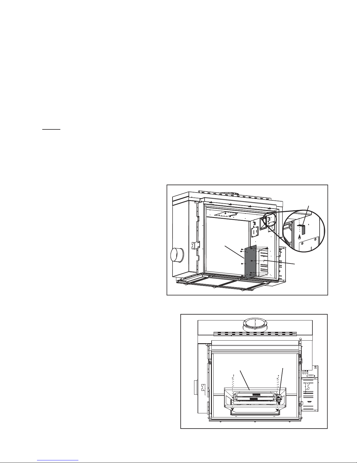
2.1 ACCESS PANEL
2.1.1 Once either door is removed (see
HD81 Installation Instructions), remove the valve access panel and the
4 retaining brackets located at the top
of the fi rebox.
2.2 BURNER ASSEMBLY
2.2.1 Attach the burner assembly to the fi rebox
base with the screws supplied, making sure
the pilot assembly is closest to the valve access opening.
ACCESS
PANEL
BURNER
ASSEMBL Y
RETAINING
BRACKETS
VALVE
ACCESS
OPENING
PILOT
ASSEMBLY
W415-0808 / 06.16.09
Page 3
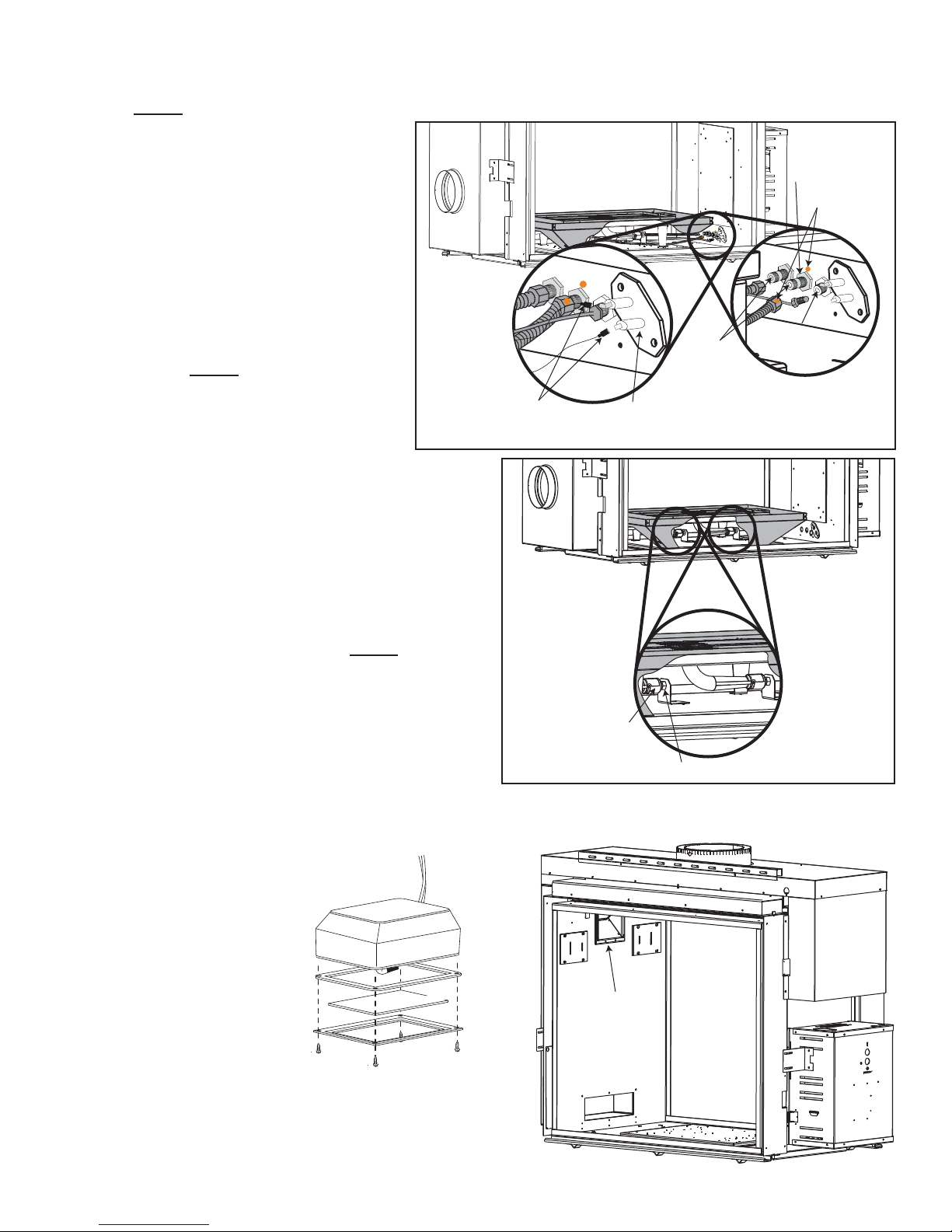
2.3 BULKHEADS
NOTE: Bulkhead covers need to be removed.
3
2.3.1 Connect the gas fl ex lines
and the pilot line to the gas
bulkheads located under the
valve access opening. Be sure
to match up the gas manifold
marked with an orange dot
with the center bulkhead, also
marked with an orange dot.
Care must be taken to ensure
the pilot line isn’t damaged and
ensuring gas tight connections
are made.
NOTE: The middle tube is the
primary burner and can not
be turned off. The outside
burner can be turned on and
off with the remote. If this
isn’t the case then switch the
fl ex lines.
2.3.2 Connect the pilot electrode leads to the
bulkhead. The leads can only fi t one way.
You need to match the 1/4” fl ag with the 1/4”
bulkhead spade and the 3/16” fl ag with the
3/16” spade.
PILOT
ELECTRODE
LEADS
PILOT
ELECTRODE
GAS
BULKHEADS
PRIMARY
BURNER
ORANGE
DOTS
PILOT
BULKHEADS
2.3.3 Ensure the 2 venturi tubes are over the
orifi ces before lighting. NOTE: It is recom-
mended at this stage to do an operational check before fi nishing installation.
2.3.4 Check for gas leaks by brushing on a soap
and water solution. Do not use open fl ame.
2.3.5 After leak test has been performed re-install
access panel with gasket.
2.4 NIGHT LIGHT™ INSTALLATION
Your HD81 comes
equipped with 2 “Night
Lights™”.
The lights have been prewired and are controlled
from the remote control.
Included with the burner
assembly are the frames,
lenses and gaskets that
need to be installed as
illustrated.
THE FIREBOX MUST
BE SEALED.
Over tightening the screws could break the lens.
“Light Leakage” from the holes in the housing lamp may
be observed. The holes in the lamp housing are necessary for ventilation and must not be covered.
COLOURED SIDE UP
GASKET
LENS
FRAME
VENTURI
TUBE
ORIFICE
NIGHT
LIGHT
W415-0808 / 06.16.09
Page 4

4
2.5 PORCELAIN BASE INSTALLATION
INSTALL IN THE FOLLOWING ORDER:
2.5.1 Side porcelain panels or brick panels must
be installed prior to porcelain base cover
plates. For side porcelain panel installation
see “PRP81 PORCELAIN REFLECTIVE
RADIANT PANEL” leafl et and for brick panel
installation see “GD844KT DECORATIVE
BRICK P ANEL - SANDSTONE” leafl et.
2.5.2. Slide the porcelain cover plates through the
front opening being careful not to scratch
the porcelain panels. The cover plates must
slide under the burner cover as shown.
Secure to the burner base with the screws
provided and repeat on other side. Porcelain wire shields sit on the cover plates as
illustrated.
PORCELAIN
COVER PLATE
PORCELAIN
WIRE SHIELD
2.6 BURNER COVER INSTALLATION
2.6.1 Lower the burner cover down onto the
burner tray and porcelain base, making
sure the pilot is properly seated through
the slot on the right side.
2.6.2 Attach burner cover with four screws as
illustrated.
2.6.3 Empty the sand into the burner tray.
Spread the sand evenly over the burner
tray.
W415-0808 / 06.16.09
Page 5

2.7 ROCK INSTALLATION
REAL ROCKS MUST NOT BE USED IN THIS APPLIANCE. HEAT WILL CAUSE THEM TO EXPLODE.
!
WARNING
5
2.7.1 Position the two rock clusters in front of the
center burner tube, ensuring the clusters are
sitting fl at on the burner and making sure not
to cover burner ports.
2.7.3 Position the four large rocks randomly along
the front, making sure not to cover burner
ports.
2.7.2 Place the large cut out rocks along the edge
of the burner, making sure not to cover any
burner ports. (There are no set locations).
2.7.4 Place the medium rocks randomly between
the other rocks, making sure not to cover
the burner ports.
2.7.5 Position the remaining little rocks randomly,
making sure not to cover the burner ports.
2.7.6 Repeat on other side.
W415-0808 / 06.16.09
Page 6

6
A
3.0 ADJUSTMENT
3.1 FLAME CHARACTERISTICS
It’s important to periodically perform a visual check of the pilot and burner fl ames. Compare them to the illustra-
tions provided. If any fl ames appear abnormal call a service person.
3.2 VENTURI ADJUSTMENT
This model has an air shutter that has been factory set open according to the chart
below:
Closing the air shutter will cause a more yellow fl ame, but can lead to carboning.
Opening the air shutter will cause a more blue fl ame, but can cause
fl ame lifting from the burner ports. The fl ame may not appear yellow
immediately; allow 15 to 30 minutes for the fi nal fl ame color to be
established.
ELECTRODE
FLAME
SENSOR
PILOT
BURNER
FLAME MUST ENVELOP
UPPER 3/8” TO 1/2” OF
FLAME SENSOR
3/8” - 1/2”
54.1
AIR
SHUTTER
OPENING
IR SHUTTER ADJUSTMENT MUST ONLY BE DONE BY A QUAL-
IFIED INSTALLER!
LP 7/16”
NG 3/16”
VENTURI
ORIFICE
BURNER
49.4
Air Shutter Openings both Burners
W415-0808 / 06.16.09
Page 7

3.0 REPLACEMENTS
Contact your dealer or the factory for questions concerning prices and policies on replacement parts. Normally
all parts can be ordered through your Authorized dealer / distributor.
FOR WARRANTY REPLACEMENT PARTS, A PHOTOCOPY OF THE ORIGINAL INVOICE WILL BE
REQUIRED TO HONOUR THE CLAIM.
When ordering replacement parts always give the following information:
• Model & Serial Number of appliance
• Installation date of appliance
• Part number
• Description of part
• Finish
* IDENTIFIES ITEMS WHICH ARE NOT ILLUSTRATED. FOR FURTHER INFORMATION, CONTACT YOUR
AUTHORIZED DEALER.
REF NO. HD81 DESCRIPTION
1 W280-0071 NIGHT LIGHT LENS FRAME
2 W290-0080 NIGHT LIGHT GASKET
3 W300-0086 CERAMIC BLUE NIGHT LIGHT LENS
4 W350-0460 ROCK BURNER HOUSING
5 W100-0113 DOUBLE TUBE BURNER
6* W175-0227 CONNECTOR, 3/8” STAINLESS STEEL FLEX
7* W175-0289 CONNECTOR, 3/8” STAINLESS STEEL FLEX (24”)
8* W550-0007 FINE AGGREGATE
9 W010-1861 2-WAY NATURAL GAS PILOT ASSEMBLY
9 W010-1862 2-WAY PROPANE GAS PILOT ASSEMBLY
10 W565-0109 GLASS BURNER SCREEN
11 W120-0064 ROCK BURNER WIRE SHIELD
12 W750-0200 FLAME SENSOR
13 W750-0201 ELECTRODE
14 W455-0070 NATURAL GAS PILOT INJECTOR
14 W455-0065 PROPANE GAS PILOT INJECTOR
15* W455-0058 #35 ORIFICE NATURAL
15* W455-0050 #55 INSIDE ORIFICE PROPANE
15* W455-0087 #52 OUTSIDE ORIFICE PROPANE
16 W200-0274 ROCK BURNER COVER
COMPONENTS
7
!
WARNING
Failure to position the parts in
accordance with this manual or failure
to use only parts specifically approved
with this appliance may result in
property damage or personal injury.
41.1
12
13
14
11
5
10
9
1
2
4
16
3
W415-0808 / 06.16.09
Page 8

8
4.0 NOTES
W415-0808 / 06.16.09
44.1
 Loading...