

Page 1
NATURAL GAS MODELS:
B81NL-1
ADD PRODUCT CODE HERE (TRADE GOTHIC LT STD FONT)
ENGLISH
PROPANE GAS MODELS:
SAFETY INFORMATION
!
WARNING
FIRE OR EXPLOSION HAZARD
Failure to follow safety warnings exactly
could result in serious injury, death, or
property damage.
- Do not store or use gasoline or other
fl ammable vapors and liquids in the vicinity of
this or any other appliance.
- WHAT TO DO IF YOU SMELL GAS:
• Do not try to light any appliance.
• Do not touch any electrical switch; do not
use any phone in your building.
• Immediately call your gas supplier from a
neighbour’s phone. Follow the gas
supplier’s instructions.
• If you cannot reach your gas supplier, call
the fi re department.
B81PL-1
FRENCH
PG. 11
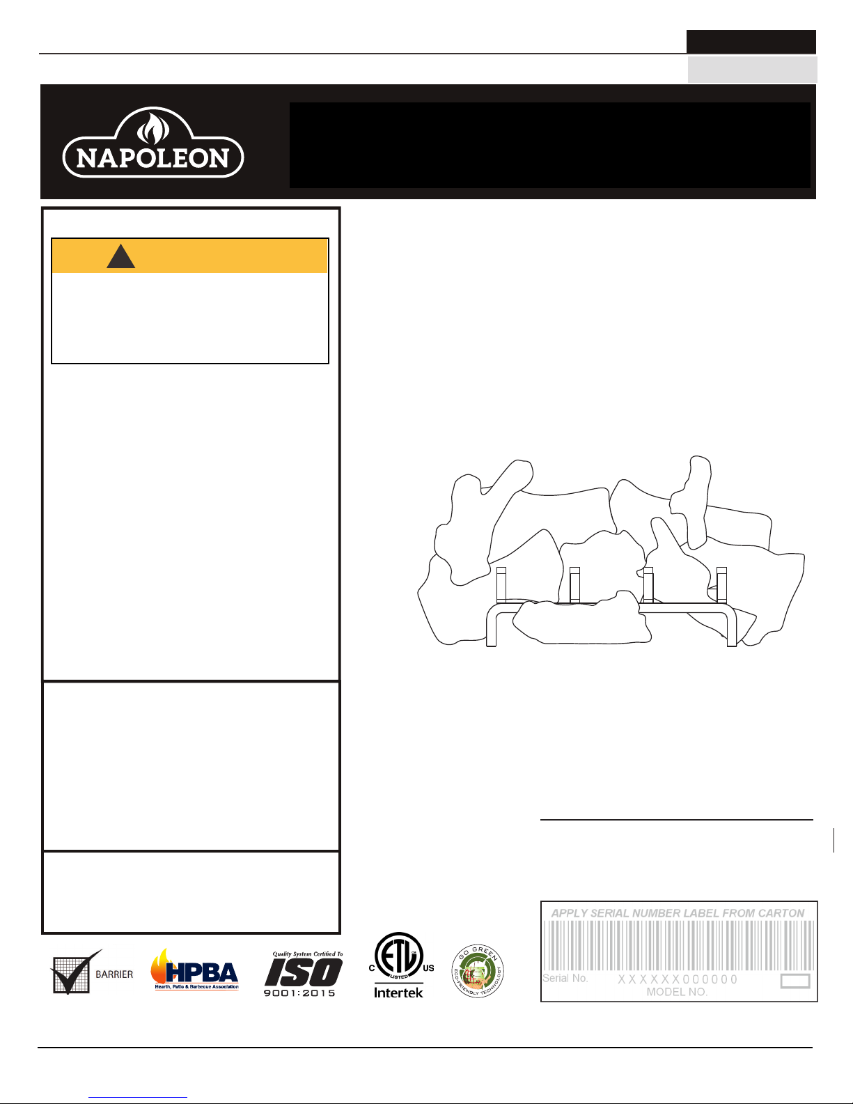
INSTALLATION AND
ADD MANUAL TITLE
OPERATION MANUAL
Product Name / Code
High Definition 81 See Thru
Log Burner Assembly
ADD PRODUCT IMAGE
(see price book)
ADD ____ ILLUSTRATED
(B81NL-1 illustrated)
- Installation and service must be
performed by a qualifi ed installer, service
agency, or the supplier.
This appliance may be installed in an aftermarket,
permanently located, manufactured home (USA
only) or mobile home, where not prohibited by
local codes.
This appliance is only for use with the type of gas
indicated on the rating plate. This appliance is
not convertible for use with other gases, unless
a certifi ed kit is used.
INSTALLER:
Leave this manual with the appliance
CONSUMER:
Retain this manual for future reference
Wolf Steel Ltd., 24 Napoleon Rd., Barrie, ON, L4M 0G8 Canada / 103 Miller Drive, Crittenden, Kentucky, USA, 41030
Phone 1 (866) 820-8686 • www.napoleonfi replaces.com • hearth@napoleonproducts.com
CSA 2.22 AND ANSI Z21.50 FOR VENTED DECORATIVE GAS APPLIANCES
CSA /
INTERTEK
LOGO
FOR INDOOR USE ONLY
CERTIFIED TO THE CANADIAN AND AMERICAN NATIONAL STANDARDS:
IF INSTALLATION + OPERATION, ADD SERIAL
NUMBER LABEL HERE
IF SEPARATE MANUALS, ADD “PLACE
BARCODE LABEL ON THE OWNER’S MANUAL”
$10.00
W415-0713 / E / 05.10.18
Page 2
EN
general information
1.0 general information 2
2.0 installation 2
2.1 access panel 2
2.2 burner assembly 2
2.3 bulkheads 3
2.4 night light™ installation 3
2.5 hearth panel installation 4
2.6 log placement 4
2.7 glowing embers 5
2.8 vermiculite 6
2.9 charcoal embers 6
2.10 charcoal lumps 6
3.0 adjustment 7
3.1 flame characteristics 7
3.2 venturi adjustment 7
4.0 replacements 8
4.1 overview 9
note:
The information throughout this manual is believed to be correct at the time of printing. Wolf Steel
Ltd. reserves the right to change or modify any information within this manual at any time without
notice. Changes, other than editorial are denoted by a vertical line in the margin.
1.0 general information
This burner and log assembly are approved for use in the HD81-1 gas fireplace only. They are not approved for
use as a stand alone appliance or in conjunction with any other appliance.
2.0 installation
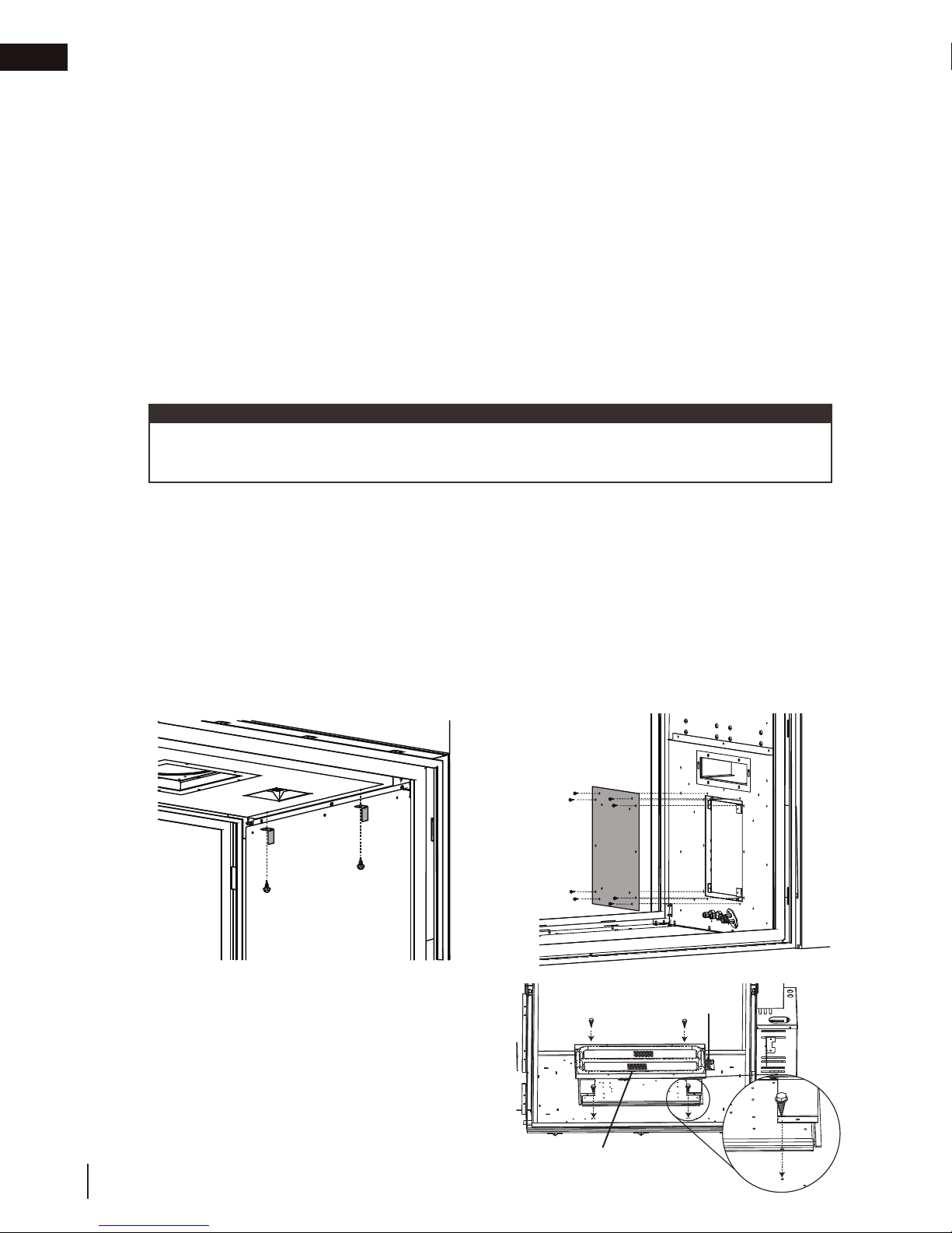
2.1 access panel
A. Once either door is removed (refer to the “door removal / installation” section of the HD81-1 manual),
remove the air manifold by removing the two retaining brackets located at the top of the firebox, see Figure
1.
B. Remove the valve access panel and gasket by removing the 8 screws, see Firgure 2.
Fig. 1 Fig. 2
2.2 burner assembly
A. Attach the burner assembly to the firebox base with
the screws supplied, ensure the pilot assembly is
closest to the valve access opening.
2
W415-0713 / E / 05.10.18
Pilot
Assembly
Burner Assembly
Page 3
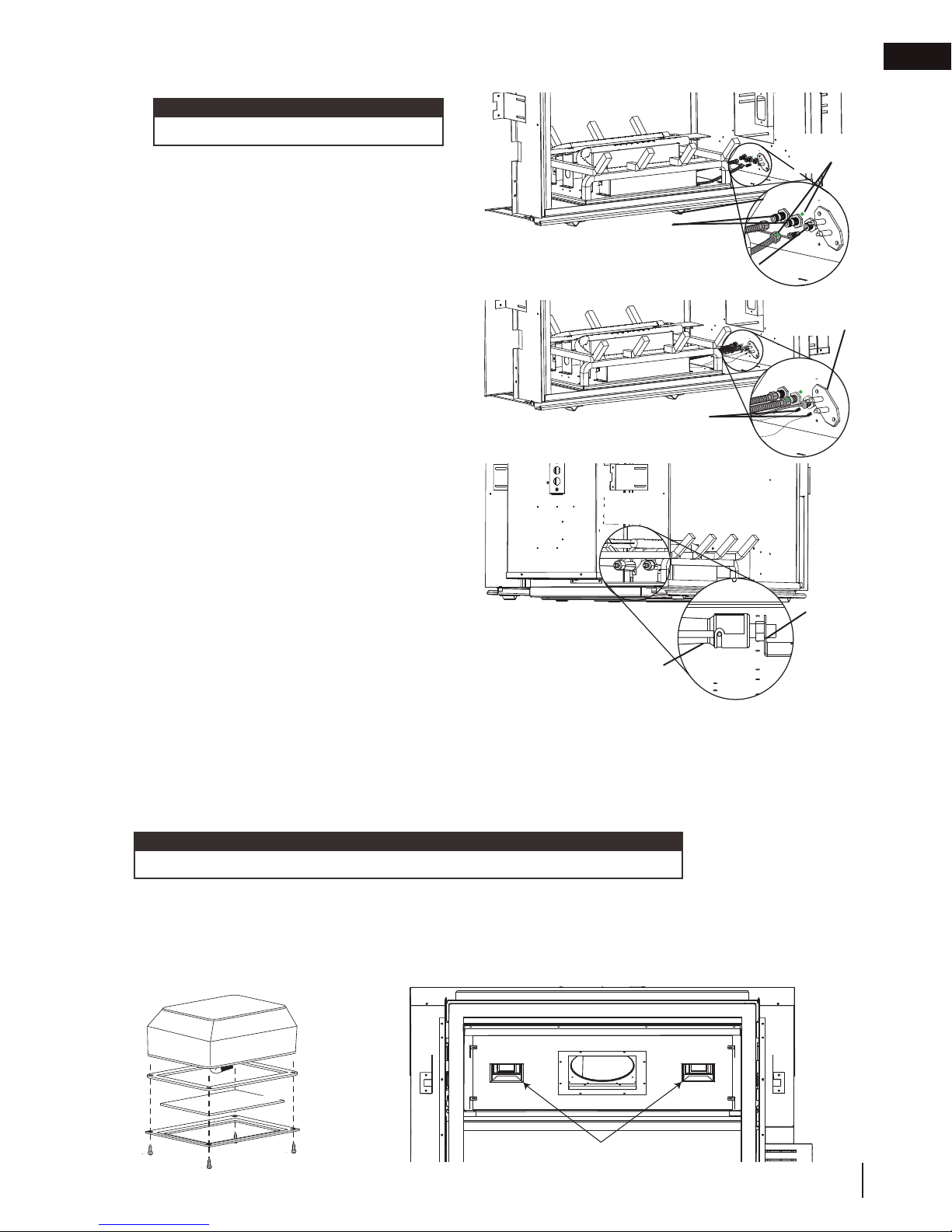
2.3 bulkheads
See Thru
Window
JOINT
D’ÉTANCHÉITÉ
LENTILLE
CADRE
CÔTÉ COLORÉ
AU-DESSUS
note:
Bulkhead covers need to be removed.
A. Connect the gas flex lines and the pilot line
to the gas bulkheads located under the valve
access opening. Be sure to match up the gas
manifold marked with a painted dot with the
center bulkhead, also marked with a painted
dot. Care must be taken to ensure the pilot
line isn’t damaged and ensuring gas tight
connections are made.
B. Connect the pilot electrode leads to the
bulkhead matching the 1/4” flag with the 1/4”
bulkhead spade and the 3/16” flag with the
3/16” spade.
C. Ensure the 2 venturi tubes are over the orifices
before lighting.
D. Check for gas leaks by brushing on a soap
and water solution. Do not use open flame.
E. After leak test has been performed reinstall
access panel with gasket.
Gas
Bulkheads
Pilot
Electrode
Leads
installation
Painted
Pilot
Bulkhead
Electrode
EN
Dots
Pilot
Orifice
Venturi
Tube
2.4 night light™ installation
The HD81-1 comes equipped with two “Night Lights™”. The lights have been pre-wired and are controlled from
the remote control.
If in the event the lamps or lens need replacing, follow the instructions below:
A. Shut off breaker at main power supply
B. Remove the four screws that secure the lens frame to the firebox sides. This frame retains the glass lens.
C. The lamp can now be accessed.
note:
Do not handle the lamp (bulb) with bare fingers, protect with a clean, dry cloth.
The lamp will pull straight out of the socket. Replace with Wolf Steel parts only, as lamp and lens are special “high
temperature” products. When re-installing, ensure integrity of gasket seal.
THE FIREBOX MUST BE SEALED.
Over tightening the screws could break the lens. “Light Leakage” from the holes in the housing lamp may be
observed. The holes in the lamp housing are necessary for ventilation and must not be covered.
GASKET
COLOURED SIDE UP
LENS
FRAME
NIGHT LIGHTS
W415-0713 / E / 05.10.18
3
Page 4

EN
!
WARNING
installation
2.5 hearth panel installation
Hearth panels are shipped separate from unit and are included with the burner assembly and the logs. Due to the
brittle material of the panels, care must be taken not to bend or force them into place.
When shipped, the hearth panels range in varying shades of Sandstone. During initial use, the panels will darken
temporarily. The appearance of the panels will permanently lighten in color with use.
INSTALL HEARTH PANELS IN THE FOLLOWING ORDER:
note:
Burner assembly must be installed first.
A. Side brick panels or porcelain panels must be installed prior to
hearth panels. For brick panel and porcelain panel installation
see leaflets supplied with kits.
B. Install the left and right hearth panels on both sides.
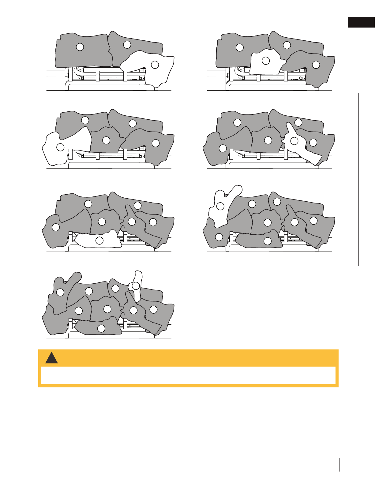
2.6 log placement
• Failure to position the logs in accordance with these diagrams or failure to use only logs specifi cally approved
with this appliance may result in property damage or personal injury.
• Logs must be placed in their exact location in the appliance. Do not modify the proper log positions, since
appliance may not function properly and delayed ignition may occur.
• The logs are fragile and should be handled with care.
PHAZERTM logs and glowing embers exclusive to Napoleon, provide a unique and realistic glowing effect that is dif-
ferent in every installation. Take the time to carefully position the glowing embers for a maximum glowing effect. Log
colours may vary. During the initial use of the appliance, the colours will become more uniform as colour pigments
burn in during the heat activated curing process.
note:
Logs C, D , E , F and G are included twice. Install these logs on the opposite side. Logs H and I are only
included once, to give it a different appearance to each side. Install logs H and I on the side that you prefer. If
desired, a second set of H and I logs are available in an upgrade kit (GL81L2) and can be purchased to make
both sides identical.
A
A
B
A. Place the rear left log (W135-0366) onto the
locating stud on the middle log support. Ensure the
hollow underside of the log is over the bend tab.
4
W415-0713 / E / 05.10.18
B. Slide the rear right log (W135-0367) from right to
left on the middle log support creating a tight fit
between logs A & B. Ensure the hollow underside
of the log is over the bend tab.
Page 5
Tear the embers into pieces and loosely layer above the burner ports covering the burner area. Care should be
taken to shred the embers into thin, small irregular pieces as only the exposed edges of the fi bre hairs will glow.
The ember material will only glow when exposed to direct fl ame; however, care should be taken to not
block off the burner ports.
Blocked burner ports can cause an incorrect fl ame pattern, carbon deposits and delayed ignition.
logs glow when exposed to direct fl ame. Use only certifi ed “glowing embers” and
your local authorized dealer / distributor.
!
WARNING
installation
EN
A
C. Place the right middle log (W135-0368) onto the far
right locating stud on the front deflector.
A
D
E
E. Place the left middle log (W135-0369) onto the far
left locating stud located on the front deflector.
A
D
E
G
B
C
B
C
B
F
C
A
D
D. Place middle log (W135-0370) onto the two center
locating studs on the front support.
A
D
E
F. Place the notch of the front right log (W135-0373)
onto the third grate.
H
E
A
D
G
B
C
B
F
B
F
C
C
G. Slide the flat portion of the front middle log (W135-
0374) under the second grate post.
H
A
E
B
D
G
I
F
C
H. Place the pin into the log locating hole of log A and
place the left crossover log (W135-0372) onto the
pin, allowing the bottom to rest on log E.
I. Place the pin into the log locating hole of log B and
place the right crossover log (W135-0371) onto the
pin, allowing the bottom to rest on log C.
J. If GL81L2 (upgrade kit) is purchased repeat “H”
and “I” on other side.
2.7 glowing embers
• Do not block or close off the burner ports. Blocked ports can cause an incorrect fl ame pattern, carbon
deposits and delayed ignition.
PHAZER™ logs available from
W415-0713 / E / 05.10.18
PHAZER™
5
Page 6
!
WARNING
!
WARNING
!
WARNING
EN
installation
2.8 vermiculite
• Do not block or close off the burner ports. Blocked ports can cause an incorrect fl ame pattern, carbon
deposits and delayed ignition.
• When supplied, charcoal embers, charcoal lumps and vermiculite are not to be placed on the burner.
Sprinkle vermiculite around the charcoal embers.
note:
Charcoal embers are not to be placed on the burner.
2.9 charcoal embers
• Do not block or close off the burner ports. Blocked ports can cause an incorrect fl ame pattern, carbon
deposits and delayed ignition.
• When supplied, charcoal embers, charcoal lumps and vermiculite are not to be placed on the burner.
Randomly place the charcoal embers along the front and sides of the log support in a realistic manner.
Fine dust found in the bottom of the bag should not be used.
note:
Charcoal embers are not to be placed on the burner.
2.10 charcoal lumps
• Do not block or close off the burner ports. Blocked ports can cause an incorrect fl ame pattern, carbon
deposits and delayed ignition.
• When supplied, charcoal embers, charcoal lumps and vermiculite are not to be placed on the burner.
Place the lumps in front of the logs in a realistic manner taking care not to block or close off any of the burner ports.
6
W415-0713 / E / 05.10.18
Page 7

3.1 flame characteristics
This appliance has an air shutter that has been factory set open according to
note:
It’s important to periodically perform a visual check of
the pilot and burner flames. Compare them to the
illustration provided. If any flames appear abnormal,
call a service person.
3.2 venturi adjustment
3.0 adjustment
adjustment
ADD IMAGE
HERE
EN
the chart below:
Regardless of venturi orientation, closing the air shutter will cause a more
yellow flame, but can lead to carbonization. Opening the air shutter will cause
a more blue flame, but can cause flame lifting from the burner ports. The flame
may not appear yellow immediately; allow 15 to 30 minutes for the final flame
colour to be established.
AIR SHUTTER ADJUSTMENT MUST ONLY BE DONE BY A QUALIFIED
INSTALLER!
It is important that the orifice is securely inserted into the venturi.
VENTURI ADJUSTMENT CHART
NG 3/16” (4.8mm)
P 7/16” (11mm)
VENTURI
BURNER
AIR
SHUTTER
OPENING
ORIFICE
W415-0713 / E / 05.10.18
7
Page 8

EN
WARNING
4.0 replacements
replacements
!
• Failure to position the parts in accordance with this manual or failure to use only parts specifi cally approved
with this appliance may result in property damage or personal injury.
Contact your dealer for questions concerning prices and policies on replacement parts. Normally, all parts can
be ordered through your Authorized dealer / distributor.
For warranty replacement parts, a photocopy of the original invoice will be required to honour the
claim.
When ordering replacement parts always give the following information:
• Model & Serial Number of appliance
• Installation date of appliance
• Part number
• Description of part
• Finish
Parts, part numbers, and availability are subject to change without notice.
Parts identifi ed as stocked will be delivered within 2 to 5 business days for most delivery
destinations.
Parts not identifi ed as stocked will be delivered within a 2 to 4 week period, for most cases.
Parts identifi ed as ‘SO’ are special order and can take up to 90 days for delivery.
8
W415-0713 / E / 05.10.18
Page 9

replacements
Ref. No.
Part number
Description
Pilot assembly (NG)
Pilot hood
Log grate assembly
Pilot orifice #35 (P)
Pilot orifice #62 (NG)
Pilot assembly (P)
04.27.18 / A
3/8” Flex connector (24”)
W175-0289
3/8” Flex connector
W175-0227
W456-0034
Burner orifice #34 (NG)
W100-0107
W456-0053
Burner orifice #53 (P)
Left side hearth pad
W135-0367
Rear right log
Middle log
Right middle log
Front middle log
Left crossover log
Right crossover log
Front right log
W361-0016
W550-0002
W550-0001
Glowing embers
Charcoal embers
Charcoal lumps
W361-0014
Vermiculite
Log locating pin
Yes
Yes
Yes
Yes
Yes
Yes
Yes
Yes
Yes
Yes
Yes
Yes
Yes
Yes
Yes
Yes
Yes
Yes
Yes
Yes
Yes
Yes
Yes
Yes
Left middle log
Rear left log
EN
4.1 overview
W415-0713 / E / 05.10.18
9
Page 10

NAPOLEON CELEBRATING OVER 40 YEARS
OF HOME COMFORT PRODUCTS
7200, Route Transcanadienne, Montréal, Québec H4T 1A3
24 Napoleon Road, Barrie, Ontario, Canada L4M 0G8
214 Bayview Drive, Barrie, Ontario, Canada L4N 4Y8
103 Miller Drive, Crittenden, Kentucky, USA 41030
Phone: 1-866-820-8686
napoleonproducts.com
Page 11

MODÈLES DE GAZ NATUREL
MODÈLES DE PROPANE
B81NL-1
B81PL-1
ADD PRODUCT CODE HERE (TRADE GOTHIC LT STD FONT)
FRANÇAIS
FRANÇAIS
MANUEL D’INSTALLATION
CONSIGNES DE SÉCURITÉ
AVERTISSEMENT!
RISQUE D’INCENDIE OU D’EXPLOSION
Incapacité à suivre ces avertissements
exactement peuvent entraîner de grave
blessures, des pertes de vie ou des
dommages matériels.
- N’entreposez pas et n’utilisez pas d’essence
ou autres liquides et vapeurs infl ammables à
proximité de cet appareil ou tout autre appareil.
- QUE FAIRE SI VOUS DÉTECTEZ UN
ODEUR DE GAZ:
• N’allumez aucun appareil.
• Ne touchez à aucun interrupteur
électrique; n’utilisez aucun téléphone dans
votre immeuble.
• Appelez immédiatement votre fournisseur
de gaz d’un téléphone voisin. Suivez ses
instructions.
• Si vous ne pouvez pas rejoindre votre
fournisseur de gaz, appelez le service des
incendies.
- L’installation et l’entretien doivent être faits par
un installateur qualifi é, une agence d’entretien
ou le fournisseur.
ADD MANUAL TITLE
ET D’OPÉRATION
Product Name / Code
Série Haute Définition 81 Binaire
Ensemble de Brûleur avec Bûches
ADD PRODUCT IMAGE
(see price book)
ADD ____ ILLUSTRATED
(B81NL-1 illustré)
Cet appareil peut être installé dans une maison
préfabriquée (mobile) déjà installée à demeure
si les règlements locaux le permettent.
Cet appareil doit être utilisé uniquement
avec le type de gaz indiqué sur la plaque
d’homologation. Cet appareil ne peut être
converti à d’autres gaz, sauf si une trousse de
conversion est utilisée.
INSTALLATEUR:
Laissez ce manual avec l’appareil
PROPRIÉTAIRE:
Conservez ce manuel pour consultation
ultérieure
Wolf Steel Ltd., 24 Napoleon Rd., Barrie, ON, L4M 0G8 Canada / 103 Miller Drive, Crittenden, Kentucky, USA, 41030
Téléphone 1(866)820-8686 • www.napoleonfoyers.com • hearth@napoleonproducts.com
$10.00
POUR USAGE INTÉRIEUR SEULEMENT
CERTIFIÉ SELON LES NORMES NATIONALES CANADIENNES ET AMÉRICANES:
CSA 2.22 ET ANSI Z21.50 POUR LES APPAREILS À GAZ DÉCORATIF À ÉVACUATION
IF INSTALLATION + OPERATION, ADD SERIAL
CSA /
INTERTEK
LOGO
IF SEPARATE MANUALS, ADD “PLACE
BARCODE LABEL ON THE OWNER’S MANUAL”
NUMBER LABEL HERE
W415-0713 / E / 05.10.18
Page 12

information générale
FR
1.0 information générale 12
2.0 installation 12
2.1 panneau d’accès 12
2.2 assemblage du brûleur 12
2.3 raccords 13
2.4 installation de la lumière de veille 13
2.5 installation des panneaux de plancher 14
2.6 disposition des bûches 14
2.7 braises incandescentes 16
2.8 vermiculite 16
2.9 braises de charbon 16
2.10 morceaux de charbon 16
3.1 caractéristiques de la flamme 17
3.0 réglages 17
4.0 rechanges 18
4.1 vue d’ensemble 19
note:
L’information contenue dans ce manuel est jugée correcte au moment de l’impression. Wolf Steel Ltée. se
réserve le droit de modifier ou de modifier toute information contenue dans ce manuel à tout moment sans
préavis. Les modifications, autres que les éditoriaux, sont désignées par une ligne verticale dans la marge.
1.0 information générale
Ce brûleur et cet assemblage de bûches sont approuvés pour utilisation dans l’appareil au gaz HD81-1 seulement.
Ils ne sont pas approuvés pour utilisation comme appareil autonome ou avec n’importe quel autre appareil.
2.0 installation
2.1 panneau d’accès
A. Une fois que vous avez enlevé une des portes (voir la section « installation / enlèvement de la porte » dans
votre manuel d’instructions d’installation du HD81-1), retirer le collecteur d’air en enlever les deux supports
de fixation dans la partie supérieure de la chambre de combustion, voir Figure 1.
B. Retirez le panneau d’accès de la soupape et le joint d’étancheité en enlever les 8 vis, voir Figure 2.
Fig. 1 Fig. 2
2.2 assemblage du brûleur
A. Fixez le brûleur à la base de la chambre de
combustion à l’aide des vis fournies, en vous
assurant que l’assemblage de veilleuse est
placé du côté de l’ouverture d’accès de la
soupape.
Assemblage
de veilleuse
12
W415-0713 / E / 05.10.18
Assemblage
du brûleur
Page 13

Vue en
crevée
2.3 raccords
D’ÉTANCHÉITÉ
note:
Les couvercles des raccords doivent être retirés.
A. Branchez les conduites de gaz flexibles et la
conduite de la veilleuse aux raccords de gaz
situés en dessous de l’ouverture d’accès de la
soupape. Assurez-vous de faire correspondre le
collecteur de gaz marqué avec un point peints
avec le raccord central, également marqué avec
un point vert. Utilisez de prudence pour vous
assurer de ne pas endommager la conduite de
la veilleuse et que les connexions de gaz sont
bien serrées.
B. Branchez les fils d’électrode de la veilleuse
au raccord en faisant correspondre l’embout
femelle de 1/4” à l’embout mâle de 1/4” et
l’embout femelle de 3/16” à l’embout mâle de
3/16”.
C. Assurez-vous que les 2 tubes de venturi sont
par dessus les injecteurs avant d’allumer
D. Vérifiez pour des fuites de gaz en appliquant une
solution d’eau savonneuse. N’utilisez pas une
flamme nue.
E. Après avoir vérifié pour les fuites, réinstallez le
panneau d’accès avec le joint d’étanchéité.
installation
FR
Points
peints
Raccords
de gaz
Raccord de
veilleuse
Électrode
de veilleuse
Fils
d’électrode
de veilleuse
Injecteur
Tube de
venturi
2.4 installation de la lumière de veille
Cette appareil est équipé de deux lumières de veille. Les lumières de veille sont précâblées et sont contrôlées par la
télécommande.
Si vous devez remplacer l’ampoule ou la lentille, suivez les instructions suivantes:
A. Désactivez le disjoncteur à l’entrée d’alimentation principale.
B. Retirez les quatre vis servant à fixer le cadre aux côtés de la chambre de combustion. Ce cadre sert à retenir la
lentille.
C. Vous pouvez maintenant accéder à l’ampoule.
note:
Lorsque vous manipulez l’ampoule, ne la laissez pas entrer en contact directe avec vos doigts, protégez-la
avec un linge propre et sec.
L’ampoule s’enlève en la tirant hors de la douille. Remplacez par des pièces Wolf Steel ltée uniquement, car l’ampoule
et la lentille sont des produits spécialement conçus pour les hautes températures. Lors de la réinstallation, vérifiez
l’intégrité du joint d’étanchéité.
LA CHAMBRE DE COMBUSTION DOIT ÊTRE SCELLÉE.
Le serrage excessif des vis risque de briser la lentille. Il est possible que des « fuites de lumière » soient visibles au niveau des
trous dans le boîtier de la lumière. Ces derniers sont nécessaires à la ventilation et ne doivent pas être couverts.
CÔTÉ COLORÉ
AU-DESSUS
JOINT
LENTILLE
CADRE
NIGHT LIGHTS
LUMIÈRE DE VEILLE
W415-0713 / E / 05.10.18
13
Page 14

!
AVERTISSEMENT
installation
2.5 installation des panneaux de plancher
FR
Les panneaux de plancher sont expédiés séparément de l’unité et ils sont inclus avec l’assemblage du brûleur et les
bûches. En raison de la fragilité des panneaux, prenez grand soin de ne pas courber ou forcer les panneaux pour
les mettre en place.
La couleur des panneaux expédiés varie de différentes teintes de grès. Lors de l’utilisation initiale, les panneaux
fonceront de façon temporaire, pour ensuite pâlir de façon permanente à l’usage.
INSTALLEZ LES PANNEAUX DE PLANCHER SELON L’ORDRE SUIVANT:
note:
L’assemblage du brûleur doit être installé premier.
A. Les panneaux de brique ou de porcelaine latéraux doivent être
installés avant les panneaux de plancher. Pour l’installation des
panneaux de brique ou porcelaine, voir les feuillet fournies avec
les ensembles.
B. Installez les panneaux de plancher gauches et droits des deux
côtés.
PANNEAUX DE PLANCHER
2.6 disposition des bûches
• Omettre de positionner les bûches conformément aux schémas ou omettre d’utiliser uniquement des bûches
spécifi quement approuvées pour cet appareil peut causer des dommages matériels ou des blessures
corporelles.
• Les bûches doivent être placées correctement à l’intérieur de l’appareil. Ne changez pas la position des
bûches car l’appareil risque de ne pas fonctionner adéquatement et un retard d’allumage risque de se
produire.
• Les bûches sont fragiles et devraient être manipulées avec soin.
Les bûches PHAZERMD et les braises incandescentes, exclusives aux appareils Napoléon, créent un effet incandescent réaliste et unique qui est différent dans chaque installation. Prenez le temps de bien installer les braises incandescentes pour obtenir le meilleur effet possible. La couleur des bûches peut varier. Lors de la première utilisation
de l'appareil, les couleurs deviendront plus uniformes à mesure que leurs pigments seront «absorbés» pendant le
procédé de «cuisson».
note:
L’ensemble comprend un double des bûches C, D , E , F et G. Installez ces bûches du côté opposé.
L’ensemble comprend une seule bûche H et I afin de conférer une apparence différente de chaque côté.
Installez les bûches H et I du côté que vous préférez. Si vous désirez un deuxième ensemble des bûches H et
I, vous pouvez acheter l’ensemble GL81L2 pour que les deux côtés soient identiques.
14
W415-0713 / E / 05.10.18
Page 15

installation
FR
A
A. Placez la bûche gauche arrière (W135-0366) sur la
tige du centre du support à bûches. Assurez-vous
que le creux sous la bûche est au-dessus de la
patte.
A
C. Placez la bûche centrale droite (W135-0368) sur la
tige à l’extrême droite située sur le déflecteur avant.
A
B
C
B
A
B. Glissez la bûche gauche droite (W135-0367) du
droite vers la gauche sur le support à bûches pour
créer un emboîtement serré entre les bûches A et
B. Assurez-vous que le creux sous la bûche est
au-dessus de la patte.
A
D
D. Placez la bûche centrale (W135-0370) sur les deux
tiges centrales sur le support avant.
A
B
B
C
B
D
E
E. Placez la bûche centrale gauche (W135-0369) sur la
tige à l’extrême gauche située sur le déflecteur avant.
A
E
G. Glissez la portion plate de la bûche de l’avant
centrale (W135-0374) sous la deuxième tige de la
grille.
H
E
D
G
A
D
F
B
F
C
B
C
I
C
D
E
F. Placez l’encoche de la bûche de l’avant droite
(W135-0373) sur la troisième patte de la grille.
H
E
H. Placez la tige dans le trou de positionnement de la
bûche A et placez la bûche croisé gauche (W135-
0372) sur la tige, il devrait se reposer sur la bûche
E.
I. Placez la tige dans le trou de positionnement de la
bûche B et placez la bûche croisé droite (W135-
0371) sur la tige, il devrait se reposer sur la bûche
C.
A
D
G
F
B
C
C
F
G
J. Si vous achetez l’ensemble GL81L2 (bûches
additionnelles), répétez les sections “H” et “I” de
l’autre côté.
W415-0713 / E / 05.10.18
15
Page 16

Déchirez les braises incandescentes en morceaux et placez une couche lâche sur le grillage du brûleur. Les
braises devraient être déchirées très soigneusement en petits morceaux
des fi bres exposées à la fl amme directe deviendront incandescents.
fl amme directe; cependant, il faut veiller à ne pas bloquer ou fermez les orifi ces du brûleur.
Le blocage des orifi ces du brûleur peut créer une fl amme irrégulière, des dépôts de carbone et un retard
d’allumage. Les bûches
exposées à la fl amme directe deviendront incandescents. Utilisez seulement
les “braises incandescentes” et bûches
!
AVERTISSEMENT
!
AVERTISSEMENT
!
AVERTISSEMENT
!
AVERTISSEMENT
installation
2.7 braises incandescentes
FR
• Obstruez pas ni fermer les orifi ces du brûleur. Le blocage des orifi ces du brûleur peut créer une fl amme
irrégulière, des dépôts de carbone et un retard d’allumage.
minces irréguliers, car seuls les côtés
Les braises n’allumer lorsque exposés à
PHAZER
MD
PHAZER
MD
disponible de votre détaillant autorisé locale.
2.8 vermiculite
• Obstruez pas ni fermer les orifi ces du brûleur. Le blocage des orifi ces du brûleur peut créer une fl amme
irrégulière, des dépôts de carbone et un retard d’allumage.
• Si équipée, les braises de charbon de bois, les morceaux de charbon et la vermiculite ne doivent pas être
placés sur le brûleur.
Éparpillez la vermiculite autour des braises de charbon de bois.
note:
La vermiculite ne doit pas être placée sur le brûleur.
2.9 braises de charbon
• Obstruez pas ni fermer les orifi ces du brûleur. Le blocage des orifi ces du brûleur peut créer une fl amme
irréguliére, des dépôts de cabone et un retard d’allumage.
• Si équipée; les braises de charbon de bois, les morceaux de charbon et la vermiculite ne doivent pas être
placés sur le brûleur.
Éparpillez les braises à l’avant et sur les côtées du support à bûches de façon à créer un effet réaliste.
N’utilisez pas la fi ne poussière qui reste au fond du sac.
note:
Les braises de charbon de bois ne doivent pas être placée sur le brûleur.
2.10 morceaux de charbon
• Obstruez pas ni fermer les orifi ces du brûleur. Le blocage des orifi ces du brûleur peut créer une fl amme
irrégulière, des dépôts de carbone et un retard d’allumage.
• Si équipée, les braises de charbon de bois, les morceaux de charbon et la vermiculite ne doivent pas être
placés sur le brûleur.
Placez les morceaux de charbon devant les bûches de façon réaliste. Prenez garde de ne pas bloquer ou
fermez les orifi ces du brûleur.
16
W415-0713 / E / 05.10.18
Page 17

3.1 caractéristiques de la flamme
Il est important d’effectuer périodiquement une
inspection visuelle de la flamme de la veilleuse et du
brûleur. Comparez-les à ces illustrations. Si des
flammes paraissent anormales, contactez un
technicien de service.
3.0 réglages
réglages
ADD IMAGE
HERE
FR
W415-0713 / E / 05.10.18
17
Page 18

AVERTISSEMENT
la livraison.
4.0 rechanges
rechanges
FR
!
• Omettre de positionner les pièces conformément à ce manuel ou d’utiliser uniquement des pièces
spécifi quement approuvées pour cet appareil peut causer des dommages matériels ou des blessures
corporelles.
Contactez votre détaillant pour les questions concernant les prix et la disponibilité des pièces de remplacement. Normalement, toutes les pièces peuvent être commandées chez votre détaillant autorisé.
Pour un remplacement de pièce sous garantie, une photocopie de la facture originale sera requise
afi n de pouvoir honorer la demande.
Lorsque vous commandez des pièces, donnez toujours l’information suivante:
• Modèle et numéro de série de l’appareil
• Date d’installation de l’appareil
• Numéro de la pièce
• Description de la pièce
• Fini
Pièces, numéro des pièces et s’il soit disponible peut changer sans préavis.
Parties identifi ées comme garnie seront livrés dans 2 à 5 jours pour la plupart des destinations de
livraison.
Pièces non identifi ées que stockés seront livrés dans un délai de 2 à 4 semainres pour la plupart des
cas.
Pièces identifi ées comme « SO » sont commande spéciale et peuvent prendre jusqu’à 90 jours pour
18
W415-0713 / E / 05.10.18
Page 19

Description
Description
Assemblage de la veilleuse (GN)
W335-0039
Hotte de la veilleuse
W455-0068
Injecteur de la veilleuse #35 (P)
W455-0070
Injecteur de la veilleuse #62 (GN)
Assemblage de la veilleuse (P)
Électrode
Sonde de la flamme
W010-1946-SER
W475-0613-SER
W475-0574-SER
En stock
Oui
Oui
Oui
Oui
Oui
Oui
Oui
Oui
Oui
Oui
Oui
Oui
Oui
Oui
Oui
Oui
Oui
Oui
Oui
Oui
Oui
Oui
Oui
Oui
En stock
Assemblage du grille bûche
Brique de plancher de côté droite
Brûleur tubulaire du côté droite
Injecteur de la veilleuse #34 (GN)
Bûche arrière gauche
Bûche arrière droite
Bûche centrale de l’avant
Vermiculite
Tube de veilleuse, raccord
Tube de veilleuse, raccord (24”)
rechanges
FR
4.1 vue d’ensemble
W361-0016
W550-0002
W550-0001
W361-0014
W175-0289
W175-0227
W415-0713 / E / 05.10.18
19
Page 20

NAPOLÉON CÉLÈBRE PLUS DE 40 ANS D’EXISTENCE
CONSACRÉS À LA CONCEPTION DE PRODUITS DE CONFORT
7200, Route Transcanadienne, Montréal, Québec H4T 1A3
24 Napoleon Road, Barrie, Ontario, Canada L4M 0G8
214 Bayview Drive, Barrie, Ontario, Canada L4N 4Y8
103 Miller Drive, Crittenden, Kentucky, USA 41030
Téléphone: 1-866-820-8686
napoleonproducts.com
 Loading...