

Page 1
NATURAL GAS MODELS:
B81NS-1
ADD PRODUCT CODE HERE (TRADE GOTHIC LT STD FONT)
ENGLISH
PROPANE GAS MODELS:
SAFETY INFORMATION
!
WARNING
FIRE OR EXPLOSION HAZARD
Failure to follow safety warnings exactly
could result in serious injury, death, or
property damage.
- Do not store or use gasoline or other
fl ammable vapors and liquids in the vicinity of
this or any other appliance.
- WHAT TO DO IF YOU SMELL GAS:
• Do not try to light any appliance.
• Do not touch any electrical switch; do not
use any phone in your building.
• Immediately call your gas supplier from a
neighbour’s phone. Follow the gas
supplier’s instructions.
• If you cannot reach your gas supplier, call
the fi re department.
B81PS-1
FRENCH
PG. 9
INSTALLATION AND
ADD MANUAL TITLE
OPERATION MANUAL
Product Name / Code
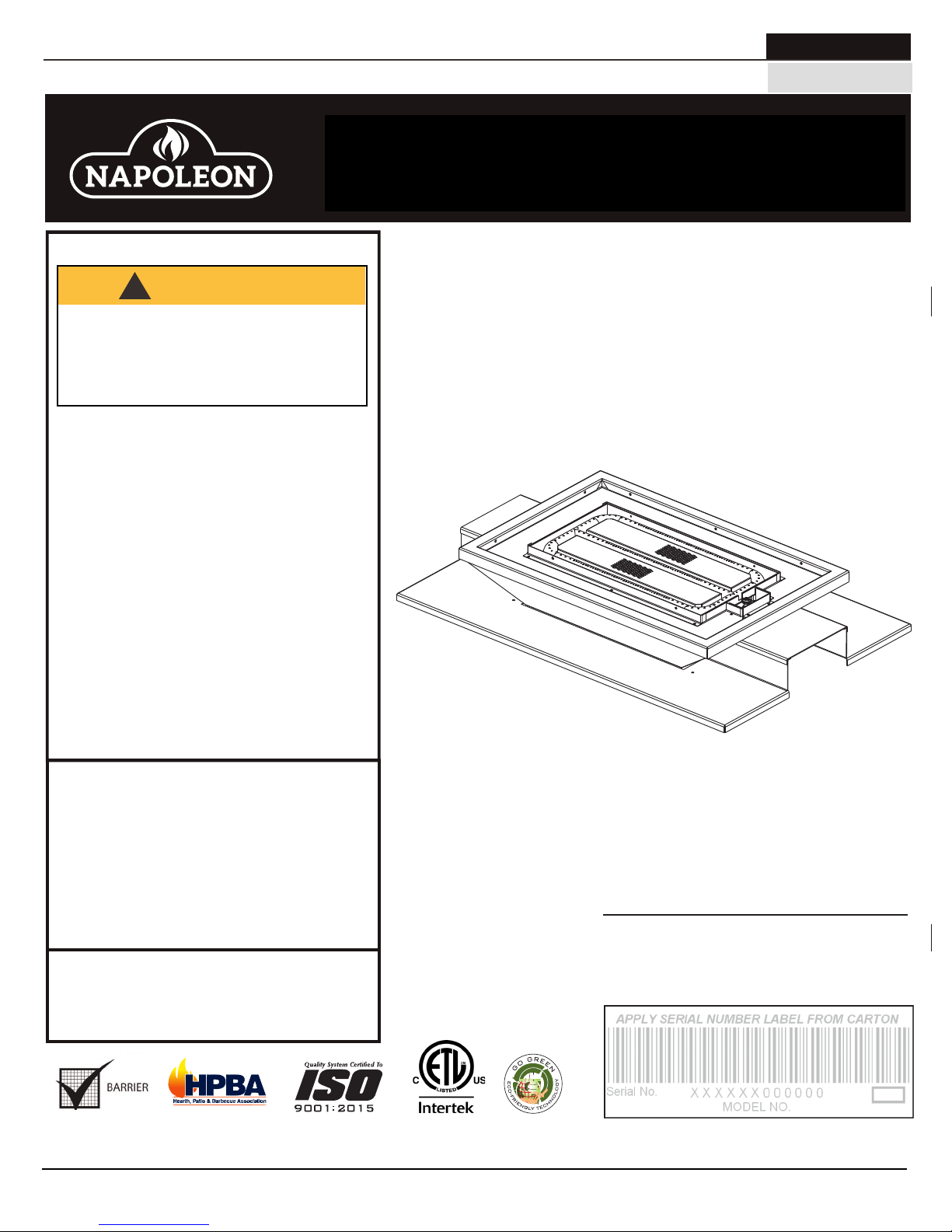
High Definition 81 See Thru
Mineral Rock Burner Assembly
ADD PRODUCT IMAGE
(see price book)
ADD ____ ILLUSTRATED
(B81NS-1 illustrated)
- Installation and service must be
performed by a qualifi ed installer, service
agency, or the supplier.
This appliance may be installed in an aftermarket,
permanently located, manufactured home (USA
only) or mobile home, where not prohibited by
local codes.
This appliance is only for use with the type of gas
indicated on the rating plate. This appliance is
not convertible for use with other gases, unless
a certifi ed kit is used.
INSTALLER:
Leave this manual with the appliance
CONSUMER:
Retain this manual for future reference
Wolf Steel Ltd., 24 Napoleon Rd., Barrie, ON, L4M 0G8 Canada / 103 Miller Drive, Crittenden, Kentucky, USA, 41030
Phone 1 (866) 820-8686 • www.napoleonfi replaces.com • hearth@napoleonproducts.com
CSA 2.22 AND ANSI Z21.50 FOR VENTED DECORATIVE GAS APPLIANCES
CSA /
INTERTEK
LOGO
FOR INDOOR USE ONLY
CERTIFIED TO THE CANADIAN AND AMERICAN NATIONAL STANDARDS:
IF INSTALLATION + OPERATION, ADD SERIAL
NUMBER LABEL HERE
IF SEPARATE MANUALS, ADD “PLACE
BARCODE LABEL ON THE OWNER’S MANUAL”
$10.00
W415-0808 / E / 05.11.18
Page 2
EN
general information
1.0 general information 2
2.0 installation 2
2.1 access panel 2
2.2 burner assembly 2
2.3 bulkheads 3
2.4 night light™ installation 3
2.5 porcelain base installation 4
2.6 burner cover installation 4
2.7 rock installation 5
3.0 adjustment 6
3.1 flame characteristics 6
3.2 venturi adjustment 6
4.0 replacements 6
4.1 overview 7
note:
The information throughout this manual is believed to be correct at the time of printing. Wolf Steel
Ltd. reserves the right to change or modify any information within this manual at any time without
notice. Changes, other than editorial are denoted by a vertical line in the margin.
1.0 general information
This rock burner assembly is approved for use in the HD81-1 gas appliance only. It is not approved for use as a
stand alone appliance or in conjunction with any other appliance.
2.0 installation
2.1 access panel
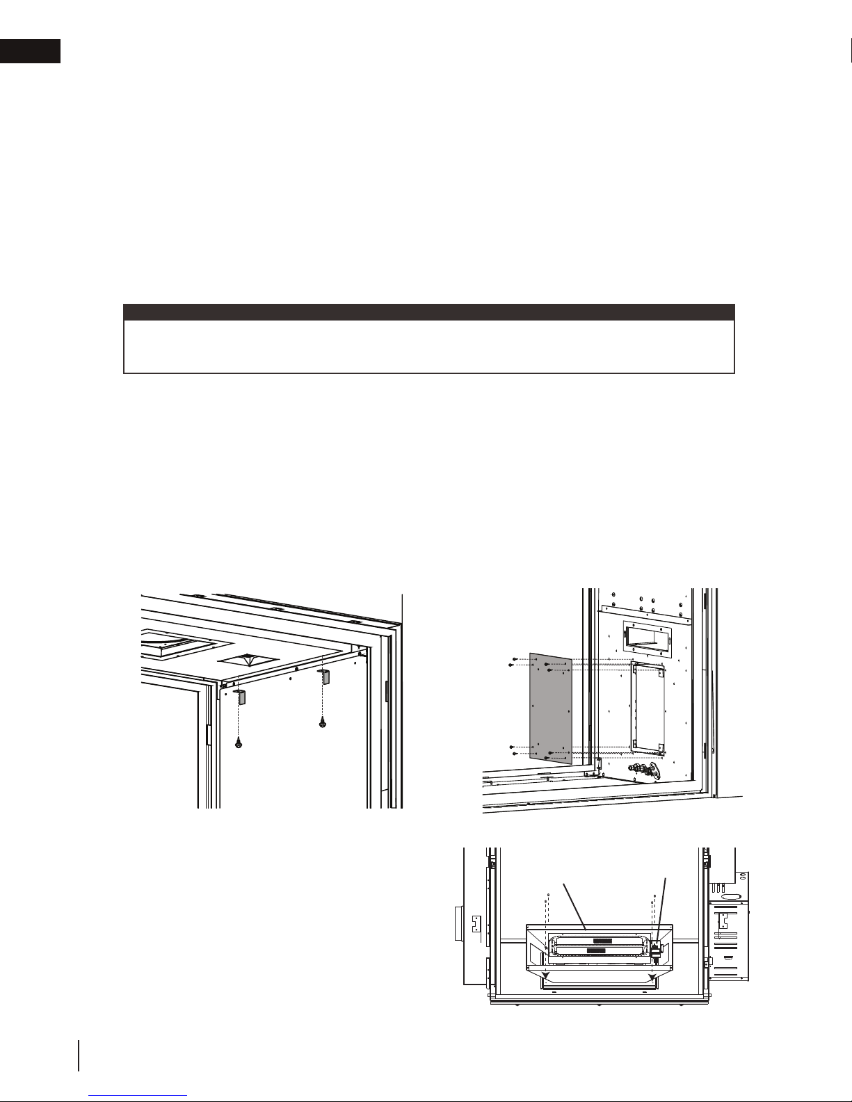
A. Once either door is removed (refer to the “door removal / installation” section of the HD81-1 manual),
remove the air manifold by removing the two retaining brackets located at the top of the firebox, see Figure
1.
B. Remove the valve access panel and gasket by removing the 8 screws, see Firgure 2.
Fig. 1 Fig. 2
2.2 burner assembly
A. Attach the burner assembly to the firebox base
with the screws supplied, making sure the pilot
assembly is closest to the valve access opening.
BURNER
ASSEMBLY
PILOT
ASSEMBLY
2
W415-0808 / E / 05.11.18
Page 3
ORIFICE
JOINT
D’ÉTANCHÉITÉ
LENTILLE
CADRE
CÔTÉ COLORÉ
AU-DESSUS
installation
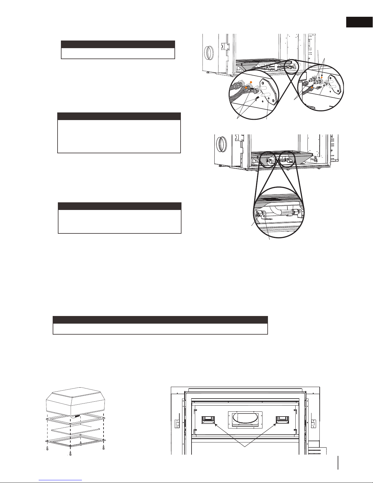
2.3 bulkheads
note:
Bulkhead covers need to be removed.
A. Connect the gas flex lines and the pilot line to the gas
bulkheads located under the valve access opening.
Be sure to match up the gas manifold marked with
a dot with the center bulkhead, also marked with a
dot. Care must be taken to ensure the pilot line isn’t
damaged and ensuring gas tight connections are
made.
note:
The middle tube is the primary burner and
cannot be turned off. The outside burner can
PILOT
ELECTRODE
LEADS
PILOT
ELECTRODE
GAS
BULKHEADS
be turned on and off with the remote. If this
is not the case, switch the flex lines.
B. Connect the pilot electrode leads to the bulkhead. The
leads can only fit one way. You need to match the 1/4”
flag with the 1/4” bulkhead spade and the 3/16” flag
with the 3/16” spade.
C. Ensure the 2 venturi tubes are over the orifices before
lighting.
note:
At this stage, we recommend performing
an operational check before finishing
installation.
VENTURI
TUBE
D. Check for gas leaks by brushing on a soap and water
solution. Do not use open flame.
E. After leak test has been performed re-install access panel with gasket (if removed).
2.4 night light™ installation
The HD81-1 comes equipped with two “Night Lights™”. The lights have been pre-wired and are controlled from
the remote control.
In the event the lamps or lens need replacing, follow the instructions below:
A. Shut off breaker at main power supply
B. Remove the four screws that secure the lens frame to the firebox sides. This frame retains the glass lens.
C. The lamp can now be accessed.
note:
Do not handle the lamp (bulb) with bare fingers, protect with a clean, dry cloth.
PILOT
BULKHEADS
EN
PRIMARY
BURNER
DOTS
The lamp will pull straight out of the socket. Replace with Wolf Steel parts only, as lamp and lens are special “high
temperature” products. When re-installing, ensure integrity of gasket seal.
THE FIREBOX MUST BE SEALED.
Over tightening the screws could break the lens. “Light Leakage” from the holes in the housing lamp may be
observed. The holes in the lamp housing are necessary for ventilation and must not be covered.
GASKET
COLOURED SIDE UP
LENS
FRAME
NIGHT LIGHTS
W415-0808 / E / 05.11.18
3
Page 4
EN
installation
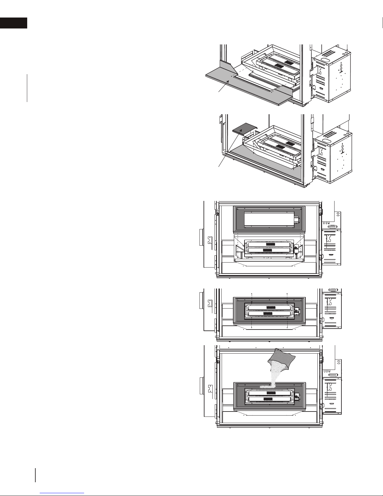
2.5 porcelain base installation
INSTALL IN THE FOLLOWING ORDER:
A. Side porcelain panels or brick panels must be
installed prior to porcelain base cover plates.
For side porcelain panel installation and for
brick panel installation, see leaflets provided
with kits.
B. Slide the porcelain cover plates through the
front opening being careful not to scratch the
porcelain panels. The cover plates must slide
under the burner cover as shown. Secure to
the burner base with the screws provided and
repeat on other side. Porcelain wire shields sit
on the cover plates as illustrated.
2.6 burner cover installation
PORCELAIN
COVER PLATE
PORCELAIN
WIRE SHIELD
A. Lower the burner cover down onto the
burner tray and porcelain base, making
sure the pilot is properly seated through
the slot on the right side.
B. Attach burner cover with four screws as
illustrated.
C. Empty the sand into the burner tray.
Spread the sand evenly over the burner
tray.
4
W415-0808 / E / 05.11.18
Page 5
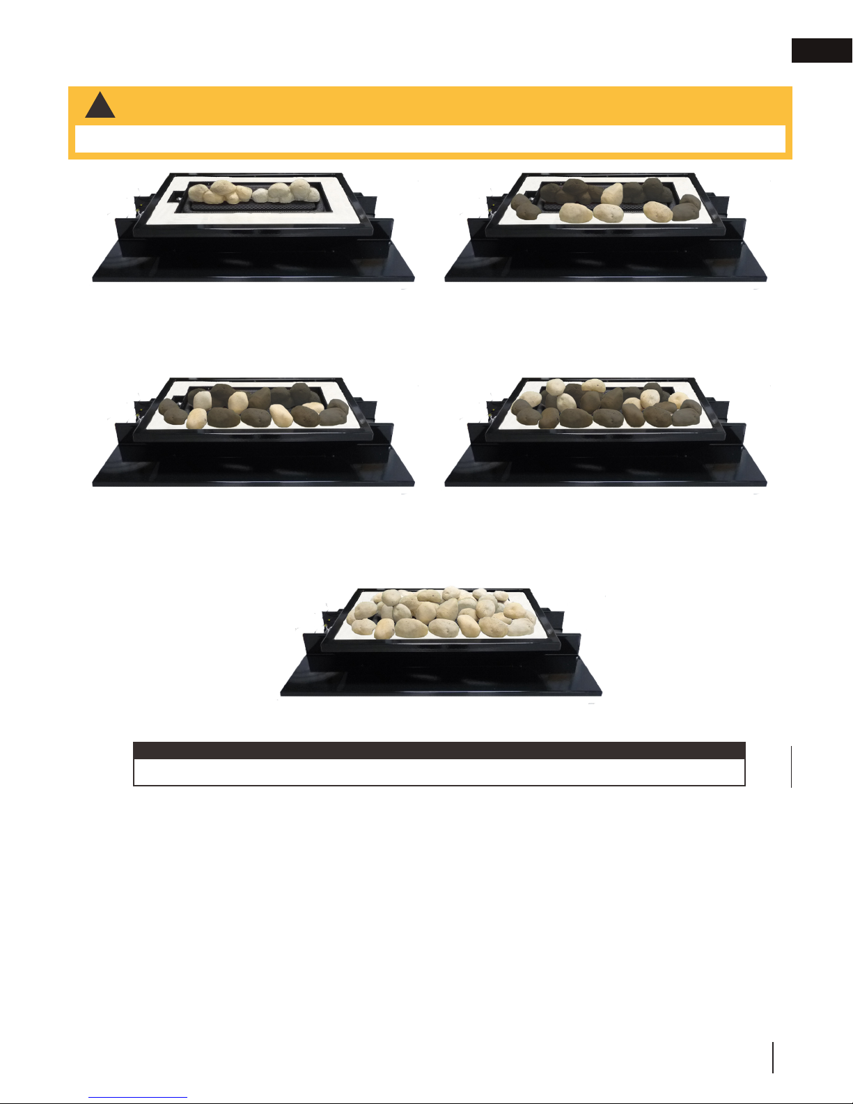
2.7 rock installation
!
WARNING
• Real rocks must not be used in this appliance. Heat will cause them to explode.
installation
EN
A. Position the rocks in front of the center burner
tube. Ensure not to cover burner ports.
C. Place a few rocks randomly between the other
rocks. Ensure not to cover burner ports.
B. Position a few large rocks randomly along the
front. Ensure not to cover burner ports.
D. Position the remaining rocks randomly. Ensure
not to cover burner ports.
note:
Rocks are for illustrative purposes only. Colour, size and shape may vary.
E. Repeat on other side.
W415-0808 / E / 05.11.18
5
Page 6

This appliance has an air shutter that has been factory set open according to
note:
EN
WARNING
Parts identifi ed as ‘SO’ are special order and can take up to 90 days for delivery.
installation
3.0 adjustment
3.1 flame characteristics
It’s important to periodically perform a visual check of
the pilot and burner flames. Compare them to the
illustration provided. If any flames appear abnormal,
call a service person.
3.2 venturi adjustment
ADD IMAGE
HERE
the chart below:
Regardless of venturi orientation, closing the air shutter will cause a more
yellow flame, but can lead to carbonization. Opening the air shutter will cause
a more blue flame, but can cause flame lifting from the burner ports. The flame
may not appear yellow immediately; allow 15 to 30 minutes for the final flame
colour to be established.
AIR SHUTTER ADJUSTMENT MUST ONLY BE DONE BY A QUALIFIED
INSTALLER!
It is important that the orifice is securely inserted into the venturi.
VENTURI ADJUSTMENT CHART
NG 3/16” (4.8mm)
P 7/16” (11mm)
VENTURI
BURNER
AIR
SHUTTER
OPENING
ORIFICE
4.0 replacements
!
• Failure to position the parts in accordance with this manual or failure to use only parts specifi cally approved
with this appliance may result in property damage or personal injury.
Contact your dealer for questions concerning prices and policies on replacement parts. Normally, all parts can
be ordered through your Authorized dealer / distributor.
For warranty replacement parts, a photocopy of the original invoice will be required to honour the
claim.
When ordering replacement parts always give the following information:
• Model & Serial Number of appliance
• Installation date of appliance
• Part number
• Description of part
• Finish
Parts, part numbers, and availability are subject to change without notice.
6
Parts identifi ed as stocked will be delivered within 2 to 5 business days for most delivery
destinations.
Parts not identifi ed as stocked will be delivered within a 2 to 4 week period, for most cases.
W415-0808 / E / 05.11.18
Page 7

installation
Part number
Ref. No.
Part number
Stocked
Stocked
12345
141512
10
11
678
9
W456-0034
W456-0052
W200-0274-BK2GL-SER
MRKS
Yes
Yes
W550-0009
W565-0109
W350-0460-BK2GL-SER
13
Yes
Yes
Yes
Yes
Yes
Yes
Yes
Yes
Yes
Yes
EN
4.1 overview
W175-0289
W175-0227
W415-0808 / E / 05.11.18
7
Page 8

NAPOLEON CELEBRATING OVER 40 YEARS
OF HOME COMFORT PRODUCTS
7200, Route Transcanadienne, Montréal, Québec H4T 1A3
24 Napoleon Road, Barrie, Ontario, Canada L4M 0G8
214 Bayview Drive, Barrie, Ontario, Canada L4N 4Y8
103 Miller Drive, Crittenden, Kentucky, USA 41030
Phone: 1-866-820-8686
napoleonproducts.com
Page 9

MODÈLES DE GAZ NATUREL
MODÈLES DE PROPANE
B81NS-1
B81PS-1
ADD PRODUCT CODE HERE (TRADE GOTHIC LT STD FONT)
FRANÇAIS
FRANÇAIS
MANUEL D’INSTALLATION
CONSIGNES DE SÉCURITÉ
AVERTISSEMENT!
RISQUE D’INCENDIE OU D’EXPLOSION
Incapacité à suivre ces avertissements
exactement peuvent entraîner de grave
blessures, des pertes de vie ou des
dommages matériels.
- N’entreposez pas et n’utilisez pas d’essence
ou autres liquides et vapeurs infl ammables à
proximité de cet appareil ou tout autre appareil.
- QUE FAIRE SI VOUS DÉTECTEZ UN
ODEUR DE GAZ:
• N’allumez aucun appareil.
• Ne touchez à aucun interrupteur
électrique; n’utilisez aucun téléphone dans
votre immeuble.
• Appelez immédiatement votre fournisseur
de gaz d’un téléphone voisin. Suivez ses
instructions.
• Si vous ne pouvez pas rejoindre votre
fournisseur de gaz, appelez le service des
incendies.
- L’installation et l’entretien doivent être faits par
un installateur qualifi é, une agence d’entretien
ou le fournisseur.
ADD MANUAL TITLE
ET D’OPÉRATION
Product Name / Code
Série Haute Définition 81 Binaire
Ensemble de Brûleur avec Lit de Roches de Minérales
ADD PRODUCT IMAGE
(see price book)
ADD ____ ILLUSTRATED
(B81NS-1 illustré)
Cet appareil peut être installé dans une maison
préfabriquée (mobile) déjà installée à demeure
si les règlements locaux le permettent.
Cet appareil doit être utilisé uniquement
avec le type de gaz indiqué sur la plaque
d’homologation. Cet appareil ne peut être
converti à d’autres gaz, sauf si une trousse de
conversion est utilisée.
INSTALLATEUR:
Laissez ce manual avec l’appareil
PROPRIÉTAIRE:
Conservez ce manuel pour consultation
ultérieure
Wolf Steel Ltd., 24 Napoleon Rd., Barrie, ON, L4M 0G8 Canada / 103 Miller Drive, Crittenden, Kentucky, USA, 41030
Téléphone 1(866)820-8686 • www.napoleonfoyers.com • hearth@napoleonproducts.com
$10.00
POUR USAGE INTÉRIEUR SEULEMENT
CERTIFIÉ SELON LES NORMES NATIONALES CANADIENNES ET AMÉRICANES:
CSA 2.22 ET ANSI Z21.50 POUR LES APPAREILS À GAZ DÉCORATIF À ÉVACUATION
IF INSTALLATION + OPERATION, ADD SERIAL
CSA /
INTERTEK
LOGO
IF SEPARATE MANUALS, ADD “PLACE
BARCODE LABEL ON THE OWNER’S MANUAL”
NUMBER LABEL HERE
W415-0808 / E / 05.11.18
Page 10

information générale
1.0 information générale 10
FR
2.0 installation 10
2.1 panneau d’accès 10
2.2 assemblage du brûleur 10
2.3 raccords 11
2.4 installation de la lumière de veille 11
2.5 installation de la plaque de recouvrment en porcelaine 12
2.6 installation du couvercle du brûleur 12
2.7 installation des roches 13
3.0 réglages 14
3.1 caractéristiques de la flamme 14
3.2 réglage du venturi 14
4.0 rechanges 14
4.1 vue d’ensemble 15
note:
L’information contenue dans ce manuel est jugée correcte au moment de l’impression. Wolf Steel Ltée. se
réserve le droit de modifier ou de modifier toute information contenue dans ce manuel à tout moment sans
préavis. Les modifications, autres que les éditoriaux, sont désignées par une ligne verticale dans la marge.
1.0 information générale
Cet assemblage de brûleur pour braises vitrifiées est approuvé pour utilisation dans l’appareil au gaz HD81-1
seulement. Il n’est pas approuvé pour utilisation comme appareil autonome ou avec n’importe quel autre appareil.
2.0 installation
2.1 panneau d’accès
A. Une fois que vous avez enlevé une des portes (voir la section « installation / enlèvement de la porte » dans
votre manuel d’instructions d’installation du HD81-1), retirer le collecteur d’air en enlever les deux supports
de fixation dans la partie supérieure de la chambre de combustion, voir Figure 1.
B. Retirez le panneau d’accès de la soupape et le joint d’étancheité en enlever les 8 vis, voir Figure 2.
Fig. 1 Fig. 2
2.2 assemblage du brûleur
Ensemble
du brûleur
A. Fixez l’ensemble du brûleur à la base de
la chambre de combustion à l’aide des vis
fournies, en vous assurant que l’assemblage
de veilleuse est placé du côté de l’ouverture
d’accès de la soupape.
Assemblage
de veilleuse
10
W415-0808 / E / 05.11.18
Page 11

installation
D’ÉTANCHÉITÉ
2.3 raccords
note:
Les couvercles des raccords doivent être retirés.
A. Branchez les conduites de gaz flexibles et la
conduite de la veilleuse aux raccords de gaz situés
en dessous de l’ouverture d’accès de la soupape.
Assurez-vous de faire correspondre le collecteur
de gaz marqué avec un point avec le raccord
central, également marqué avec un point. Usez de
prudence pour vous assurer de ne pas endommager
la conduite de la veilleuse et que les connexions de
gaz sont bien serrées.
note:
Le tube central est le brûleur primaire est ne
FILS
D’ÉLECTRODE
DE VEILLEUSE
ÉLECTRODE
DE VEILLEUSE
RACCORDS
DE GAZ
peut pas être éteint. Le brûleur externe peut être
allumé et éteint à l’aide de la télécommande.
Ci ce n’est pas le cas, inversez les conduites
flexibles.
B. Branchez les fils d’électrode de la veilleuse au raccord.
Les fils peuvent être branchés d’une seule manière.
Vous devez faire correspondre l’embout femelle de 1/4”
à l’embout mâle de 1/4” et l’embout femelle de 3/16” à
l’embout mâle de 3/16”.
C. Assurez-vous que les 2 tubes de venturi sont par dessus
les injecteurs avant d’allumer.
note:
À ce stade, avant de terminer l’installation,nous
recommandons performez une vérification opérationnelle.
D. Vérifiez pour des fuites de gaz en appliquant une solution
TUBE DE
VENTURI
INJECTEUR
d’eau savonneuse. N’utilisez pas une flamme nue.
E. Après avoir vérifié pour les fuites, réinstallez le panneau d’accès avec le joint d’étanchéité (s’il a été enlevé).
2.4 installation de la lumière de veille
Le modèle HD81-1 est équipé de deux lumières de veille. Les lumières de veille sont précâblées et sont contrôlées
par la télécommande.
Si vous devez remplacer l’ampoule ou la lentille, suivez les instructions suivantes:
A. Désactivez le disjoncteur à l’entrée d’alimentation principale.
B. Retirez les quatre vis servant à fixer le cadre aux côtés de la chambre de combustion. Ce cadre sert à retenir la
lentille.
C. Vous pouvez maintenant accéder à l’ampoule.
note:
Lorsque vous manipulez l’ampoule, ne la laissez pas entrer en contact directe avec vos doigts, protégez-la
avec un linge propre et sec.
BRÛLEUR
PRIMAIRE
POINTS
RACCORDS DE
VEILLEUSE
FR
L’ampoule s’enlève en la tirant hors de la douille. Remplacez par des pièces Wolf Steel ltée uniquement, car l’ampoule
et la lentille sont des produits spécialement conçus pour les hautes températures. Lors de la réinstallation, vérifiez
l’intégrité du joint d’étanchéité.
LA CHAMBRE DE COMBUSTION DOIT ÊTRE SCELLÉE.
Le serrage excessif des vis risque de briser la lentille. Il est possible que des « fuites de lumière » soient visibles au niveau des
trous dans le boîtier de la lumière. Ces derniers sont nécessaires à la ventilation et ne doivent pas être couverts.
CÔTÉ COLORÉ
AU-DESSUS
JOINT
LENTILLE
CADRE
NIGHT LIGHTS
LUMIÈRE DE VEILLE
W415-0808 / E / 05.11.18
11
Page 12

installation
2.5 installation de la plaque de recouvrment en porcelaine
FR
FAITES L’INSTALLATION SELON L’ORDRE SUIVANT:
A. Les panneaux de porcelaine ou de brique
latéraux doivent être installés avant les plaques de
recouvrement en porcelaine. Pour l’installation du
panneau de porcelaine latéral et pour l’installation
des panneaux de brique, voir les feuillets fournies
avec les ensembles.
B. Glissez les plaques de recouvrement en porcelaine
à travers l’ouverture avant en prenant soin de
ne pas égratigner les panneaux de porcelaine.
Les plaques de recouvrement doivent glisser
sous le couvercle du brûleur tel qu’illustré. Fixezles à la base du brûleur à l’aide des vis fournies
et répétez de l’autre côté. Les protecteurs de
fils en porcelaine reposent sur les plaques de
recouvrement tel qu’illustré.
PLAQUE DE
RECOUVREMENT
EN PORCELAINE
PROTECTEUR
DE FILS EN
PORCELAINE
2.6 installation du couvercle du brûleur
A. Installez le couvercle du brûleur sur le plateau
du brûleur et la base en porcelaine, en vous
assurant que la veilleuse en bien en place à
travers la fente du côté droit.
B. Fixez le couvercle du brûleur avec quatre vis tel
qu’illustré.
C. Videz le sable dans le plateau du brûleur. Étalez
le sable uniformément au-dessus du plateau du
brûleur.
12
W415-0808 / E / 05.11.18
Page 13

2.7 installation des roches
!
AVERTISSEMENT
• Ne pas utiliser de vraies roches dans cet appareil. La chaleur les fera exploser.
installation
FR
A. Placez les roches en avant du tube du brûleur
central en vous assurant de ne pas couvrir
les orifices du brûleur.
D.
Placez les quelques roches de façon aléatoire
entre les autres roches, en vous assurant de
ne pas couvrir les orifices du brûleur.
F. Répétez de l’autre côté.
C. Placez quelques grosses roches de façon aléa-
toire le long du devant, en vous assurant de
ne pas couvrir les orifices du brûleur.
E. Placez les roches qui reste de façon aléatoire,
en vous assurant de ne pas couvrir les
orifices du brûleur.
note:
Les roches sont à des fins d’illustration seulement. La couleur, grandeur, et forme peut varier.
W415-0808 / E / 05.11.18
13
Page 14

L’ouverture du volet d’air a été préréglée en usine selon le tableau ci-dessous:
note:
AVERTISSEMENT
la livraison.
réglage
FR
3.0 réglages
3.1 caractéristiques de la flamme
Il est important d’effectuer périodiquement une
inspection visuelle de la flamme de la veilleuse et du
brûleur. Comparez-les à ces illustrations. Si des
flammes paraissent anormales, contactez un
technicien de service.
3.2 réglage du venturi
ADD IMAGE
HERE
Indépendamment de l’orientation du venturi, plus le volet est fermé, plus la
flamme est jaune et aura tendance à causer des dépôts de carbone. Plus le
volet est ouvert, plus la flamme est bleue et plus elle a tendance à se détacher
des orifices du brûleur. La flamme peut ne pas être jaune immédiatement;
allouez de 15 à 30 minutes pour que la couleur finale de la flamme se
stabilise.
LE RÉGLAGE DU VOLET D’AIR DOIT ÊTRE EXÉCUTÉ PAR UN
TECHICIEN OU INSTALLATEUR QUALIFIÉ!
Il est important que l’injecteur soit correctement inséré dans le venturi.
TABLEAU DE RÉGLAGE DU VENTURI
GN 3/16” (4.8mm)
P 7/16” (11mm)
VENTURI
INJECTEUR
4.0 rechanges
!
• Omettre de positionner les pièces conformément à ce manuel ou d’utiliser uniquement des pièces
spécifi quement approuvées pour cet appareil peut causer des dommages matériels ou des blessures
corporelles.
OUVERTURE
DU VOLET
D’AIR
Contactez votre détaillant pour les questions concernant les prix et la disponibilité des pièces de remplacement. Normalement, toutes les pièces peuvent être commandées chez votre détaillant autorisé.
Pour un remplacement de pièce sous garantie, une photocopie de la facture originale sera requise
afi n de pouvoir honorer la demande.
Lorsque vous commandez des pièces, donnez toujours l’information suivante:
• Modèle et numéro de série de l’appareil
• Date d’installation de l’appareil
• Numéro de la pièce
• Description de la pièce
• Fini
14
Pièces, numéro des pièces et s’il soit disponible peut changer sans préavis.
Parties identifi ées comme garnie seront livrés dans 2 à 5 jours pour la plupart des destinations de
livraison.
Pièces non identifi ées que stockés seront livrés dans un délai de 2 à 4 semainres pour la plupart des
cas.
Pièces identifi ées comme « SO » sont commande spéciale et peuvent prendre jusqu’à 90 jours pour
W415-0808 / E / 05.11.18
Page 15

7
Description
2334567
Description
Assemblage de la veilleuse (GN)
Hotte de la veilleuse
L’assemblage du brûleur
1
1
En stock
En stock
Injecteur de la veilleuse #35 (P)
Assemblage de la veilleuse (P)
11.04.16
W750-0335
Électrode
W750-0336
W100-0113
813149101112158
Injecteur de la veilleuse inférieure #34(GN)
Injecteur de la veilleuse inférieure #54 (P)
141512
10
W456-0034
W456-0052
W200-0274-BK2GL-SER
Couvercle du brûleur de roches
Ensemble Mineral Rock
Oui
Oui
W550-0009
Sable blanc (8lbs)
Raccord flexible 3/8” (24”)
Raccord flexible 3/8”
W565-0109
Couvercle du brûleur
W350-0460-BK2GL-SER
Boîtier du brûleur de roches
13
Ces articles peut différer de celle illustré
Oui
rechanges
FR
4.1 vue d’ensemble
W175-0289
W175-0227
W415-0808 / E / 05.11.18
15
Page 16

NAPOLÉON CÉLÈBRE PLUS DE 40 ANS D’EXISTENCE
CONSACRÉS À LA CONCEPTION DE PRODUITS DE CONFORT
7200, Route Transcanadienne, Montréal, Québec H4T 1A3
24 Napoleon Road, Barrie, Ontario, Canada L4M 0G8
214 Bayview Drive, Barrie, Ontario, Canada L4N 4Y8
103 Miller Drive, Crittenden, Kentucky, USA 41030
Téléphone: 1-866-820-8686
napoleonproducts.com
 Loading...