

Page 1

INSTALLER: LEAVE THIS MANUAL WITH THE APPLIANCE.
CONSUMER: RETAIN THIS MANUAL FOR FUTURE REFERENCE.
NEVER LEAVE CHILDREN OR OTHER AT RISK INDIVIDUALS ALONE WITH THE APPLIANCE.
INSTALLATION AND
OPERATING INSTRUCTIONS
1.22D
Wolf Steel Ltd., 24 Napoleon Rd., Barrie, ON, L4M 0G8 Canada /
103 Miller Drive, Crittenden, Kentucky, USA, 41030
Phone (705)721-1212 • Fax (705)720-9081 • www.napoleonfi replaces.com • hearth@napoleonproducts.com
SAFETY INFORMATION
!
WARNING
If the information in these instructions are
not followed exactly, a fi re or explosion
may result causing property damage,
personal injury or loss of life.
- Do not store or use gasoline or other fl ammable
vapors and liquids in the vicinity of this or any
other appliance.
- WHAT TO DO IF YOU SMELL GAS:
• Do not try to light any appliance.
• Do not touch any electrical switch; do not use
any phone in your building.
• Immediately call your gas supplier from a
neighbour’s phone. Follow the gas supplier’s
instructions.
• If you cannot reach your gas supplier, call the
fi re department.
- Installation and service must be performed by a
qualifi ed installer, service agency, or the supplier.
CERTIFIED FOR CANADA AND UNITED STATES USING ANSI/CSA METHODS.
$10.00
HOT GLASS WILL CAUSE
BURNS.
DO NOT TOUCH GLASS UNTIL
COOLED.
NEVER ALLOW CHILDREN TO
TOUCH GLASS.
!
DANGER
A barrier designed to reduce the risk of burns from
the hot viewing glass is provided with this appliance
and shall be installed for the protection of children
and other at-risk individuals.
This appliance may be installed in an aftermarket,
permanently located, manufactured home (USA
only) or mobile home, where not prohibited by
local codes.
This appliance is only for use with the type of gas
indicated on the rating plate. This appliance is
not convertible for use with other gases, unless
a certifi ed kit is used.
Decorative Product: Not for use as a heating appliance.
EN
CERTIFIED TO CANADIAN AND AMERICAN NATIONAL STANDARDS: CSA 2.22 AND ANSI Z21.50 FOR VENTED GAS FIREPLACES.
B52NTL
NATURAL GAS
B52PTL
PROPANE
HDX52
LOG BURNER
ASSEMBLY
FR
PG
15
W415-1632 / C / 10.21.16
Page 2

2
TABLE OF CONTENTS
EN
1.0 GENERAL INFORMATION 2
2.0 INSTALLATION 2
2.1 ACCESS PANEL 2
2.2 BURNER ASSEMBLY 2
2.3 BULKHEADS 3
2.4 HEARTH PANEL INSTALLATION 4
2.5 HEARTH LOG & LOG PLACEMENT 5
2.6 CHARCOAL LUMPS 7
2.7 CHARCOAL EMBERS 7
2.8 VERMICULITE 7
2.9 GLOWING EMBERS 7
3.0 ADJUSTMENT 8
3.1 FLAME CHARACTERISTICS 8
4.0 REPLACEMENTS 9
4.1 LOG BURNER ASSEMBLY (NG) 10
4.2 LOG BURNER ASSEMBLY (P) 11
5.0 NOTES 12
NOTE: Changes, other than editorial, are denoted by a line in the margin.
1.0 GENERAL INFORMATION
This burner and log assembly are approved for use in the HDX52 gas fireplace only. They are not approved for
use as a stand alone appliance or in conjunction with any other appliance.
2.0 INSTALLATION
2.1 ACCESS PANEL
A. Remove the door,
refer to installation
instructions. Remove
the 8 securing screws
and lift the plate
up and out of the
appliance. Gasket will
need to be replaced if
damaged.
2.2 BURNER ASSEMBLY
A. Attach the burner assembly to the firebox
base with the 2 screws supplied.
OUTSIDE UNIT
INSIDE UNIT
W415-1632 / C / 10.21.16
Page 3
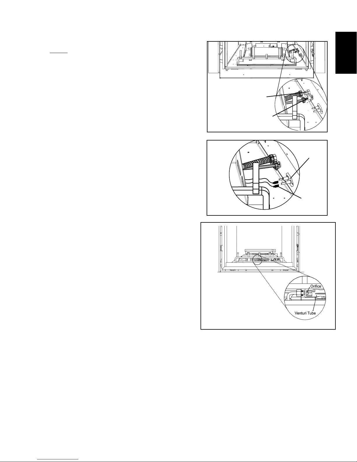
2.3 BULKHEADS
3
NOTE: Bulkhead covers need to be removed.
A. Connect the main burner gas flex line
and the pilot line to the gas fittings on the
bulkheads located under the valve access
opening.Care must be taken to ensure the
pilot line isn’t damaged and ensuring gas
tight connections are made.
B. Connect the pilot electrode lead to the
bulkhead matching the 3/16" flag with the
3/16" bulkhead spade. Do the same with the
1/4” spark lead to the 1/4” bulkhead spade.
C. Ensure the venturi tubes are over the orifice
before lighting.
EN
Main
Burner Gas
Connection
Pilot Tube
Gas Connection
Bulkhead
Pilot
Electrode
Lead
D. Check for gas leaks by brushing on a soap
and water solution. Do not use open flame.
E. After leak test has been performed re-install
access panel with gasket.
W415-1632 / C / 10.21.16
Page 4

4
2.4 HEARTH PANEL INSTALLATION
NOTE: It is recommended to remove the grate assembly prior to panel installation.
EN
Hearth floor panels are shipped separate from the appliance and are included with the mandatory brick panel
kits. Due to the brittle material of the panels, care must be taken not to bend or force them into place.
When shipped, the hearth panels range in varying shades of Sandstone / New Port. During initial use, the panels
will darken temporarily. The appearance of the panels will permanently lighten in color with use.
INSTALL HEARTH FLOOR PANELS ACCORDING TO THE INSTALLATION LEAFLET.
W415-1632 / C / 10.21.16
Page 5
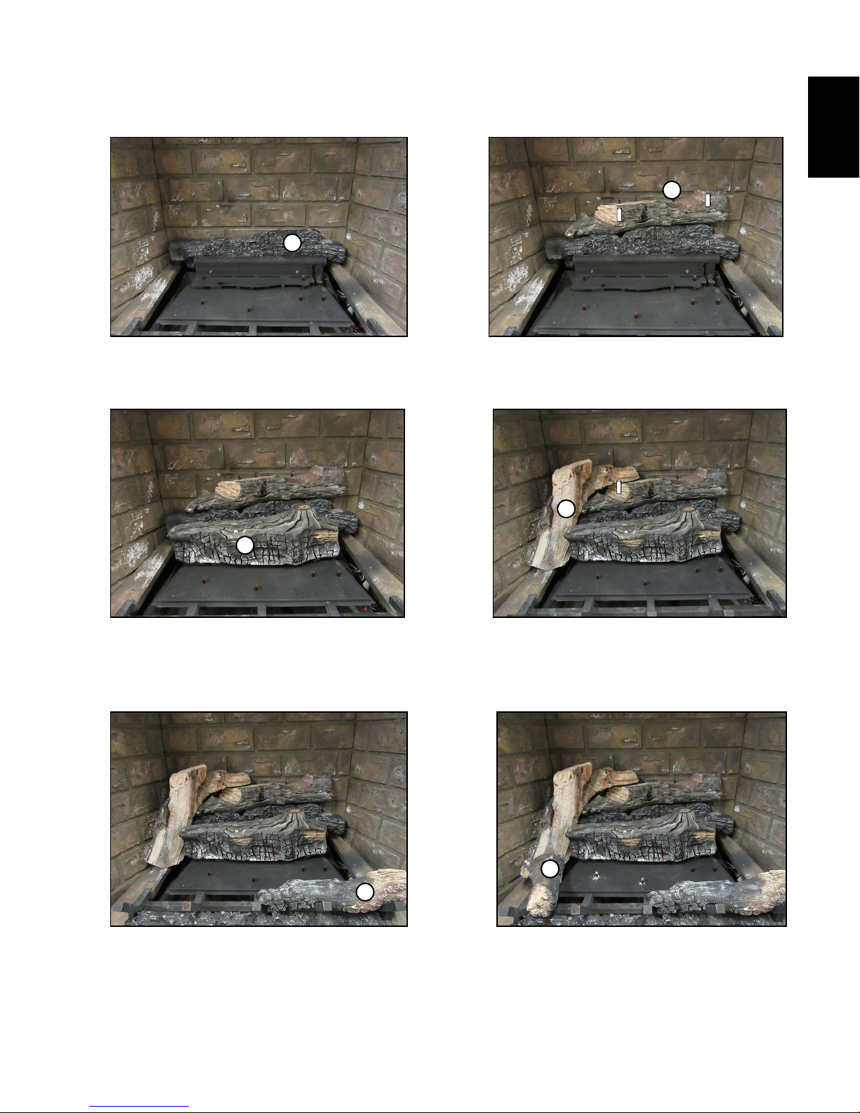
2.5 HEARTH LOG & LOG PLACEMENT
A
5
EN
B
A. Align the 2 holes in the bottom of the
bottom rear log with the studs located
on the rear log support.
C
C. Align the 2 holes in the bottom in the
middle log with the studs located on
the front log support.
B. Align the 2 pins in the bottom of the top
rear log with the holes in the top of the
bottom rear log.
D
D. Align the hole in the rear left log with the
left pin of the top rear log.
E. Line the notches in the bottom of the
front right log with the 4th and 5th grate
posts. Make sure not to cover ports.
F
E
F. Line the notch in the front left log with
the front left corner of the burner.
W415-1632 / C / 10.21.16
Page 6
EN
6
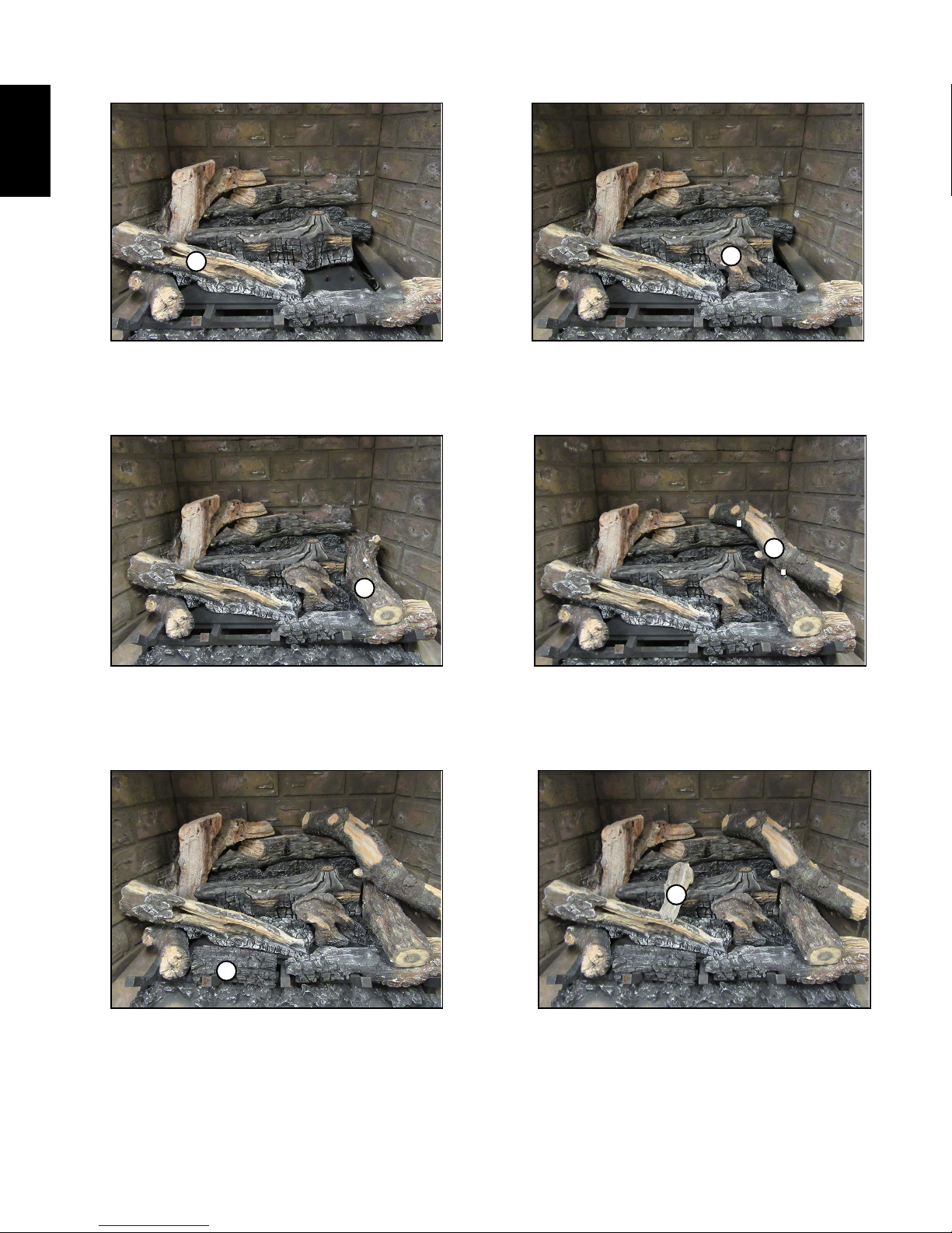
G
G. Align the 2 holes located in the bottom
of the front left crossover log with the
2 studs on the left hand side of the
burner.
I
I. Place the top right log on the notches
in the bottom rear log and the front
right log pushing back against the rear
panel.
H
H. Align the 2 holes in the bottom of the
right middle log with the 2 studs on the
right hand side of the burner.
J
J. Align the hole and the pin in the right
crossover log with the pin in the top rear
log and the hole in the top right log.
K
K. Place the notch in the front charcoal
log over the second grate post. Make
sure not to cover any ports.
W415-1632 / C / 10.21.16
L
L. Align the pin in the bottom of the
middle crossover with the hole in the
middle of the middle log resting it on
the front left crossover log.
Page 7

2.6 CHARCOAL LUMPS
Place the lumps in front of the logs in a realistic manner taking care not to block any of the burner ports.
WARNING
Randomly place the charcoal embers along the front and sides of the log support tray in a realistic manner.
Fine dust found in the bottom of the bag should not be used.
NOTE:
7
CHARCOAL EMBERS, VERMICULITE AND CHARCOAL LUMPS ARE NOT TO BE PLACED ON THE
2.7 CHARCOAL EMBERS
Charcoal embers are not to be placed on the burner.
2.8 VERMICULITE
Sprinkle vermiculite around the charcoal embers.
NOTE: Vermiculite is not to be placed on the burner
!
BURNER.
EN
34.1
32.1
33.1
2.9 GLOWING EMBERS
Tear the embers into pieces and place along the front row of ports covering all of the burner area. Care should
be taken to shred the embers into thin, small irregular pieces as only the exposed edges of the fibre hairs will
glow. The ember material will only glow when exposed to direct flame; however, care should be taken to not
block the burner ports.
Blocked burner ports can cause an incorrect flame pattern, carbon deposits and delayed ignition. Phazer™
logs glow when exposed to direct flame. Use only certified “glowing embers” and Phazer™ logs available
from your authorized dealer.
W415-1632 / C / 10.21.16
Page 8

This appliance has an air shutter that has been factory set open according
49.1
It’s important to periodically perform a visual check of the pilot and burner fl ames. Compare them to the
illustration provided. If any fl ames appear abnormal call a service person.
54.1B
8
3.0 ADJUSTMENT
EN
3.1 FLAME CHARACTERISTICS
ELECTRODE
(9.5mm - 12.7mm)
3/8” - 1/2”
FLAME
SENSOR
PILOT
BURNER
FLAME MUST ENVELOP
UPPER 3/8” (9.5mm) TO 1/2”
(12.7mm) OF FLAME SENSOR
to the chart below:
VENTURI
BURNER
Regardless of venturi orientation, closing the air shutter will cause a more
yellow flame, but can lead to carbonization. Opening the air shutter will
cause a more blue flame, but can cause flame lifting from the burner ports.
The flame may not appear yellow immediately; allow 15 to 30 minutes for
the final flame colour to be established.
ORIFICE
AIR SHUTTER ADJUSTMENT MUST ONLY BE DONE BY A QUALIFIED
INSTALLER!
Air Shutter Openings both Burners
LP F 7/16" R 1/4”
NG F 1/16" R 1/16”
AIR
SHUTTER
OPENING
W415-1632 / C / 10.21.16
Page 9

4.0 REPLACEMENTS
Contact your dealer for questions concerning prices and policies on replacement parts. Normally, all parts
can be ordered through your Authorized dealer / distributor.
FOR WARRANTY REPLACEMENT PARTS, A PHOTOCOPY OF THE ORIGINAL INVOICE WILL BE
REQUIRED TO HONOUR THE CLAIM.
When ordering replacement parts always give the following information:
•
•
•
•
•
PARTS, PART NUMBERS AND AVAILABILITY ARE SUBJECT TO CHANGE WITHOUT NOTICE.
PARTS IDENTIFIED AS STOCKED WILL BE DELIVERED WITHIN 2 TO 5 BUSINESS DAYS FOR MOST
DELIVERY DESTINATIONS.
PARTS NOT IDENTIFIED AS STOCKED WILL BE DELIVERED WITHIN A 2 TO 4 WEEK PERIOD, FOR
MOST CASES.
PARTS IDENTIFIED AS ‘SO’ ARE SPECIAL ORDER AND CAN TAKE UP TO 90 DAYS FOR DELIVERY.
WARNING
W135-0630
W135-0631
W135-0634
W135-0635
W135-0632
W135-0633
W135-0636
W135-0638
W135-0639
W135-0637
W135-0640
ITEMS MAY NOT APPEAR EXACTLY AS ILLUSTRATED
REF. NO.
PART NUMBER
DESCRIPTION
11
11
11
11
LOG, REAR TOP
LOG, MIDDLE
LOG, FRONT RIGHT
LOG, FRONT LEFT
LOG, FRONT LEFT CROSSOVER
2
10
3
4
11
11
5
11
6
7
LOG, RIGHT MIDDLE
LOG, TOP RIGHT
LOG, RIGHT CROSSOVER
LOG, FRONT CHARCOAL
LOG, MIDDLE CROSSOVER
11
8
11
9
11
1
11
FAILURE TO POSITION THE PARTS IN ACCORDANCE WITH THIS MANUAL OR FAILURE TO USE
ONLY PARTS SPECIFICALLY APPROVED WITH THIS APPLIANCE MAY RESULT IN PROPERTY
Model & Serial Number of appliance
Installation date of appliance
Part number
Description of part
Finish
9
EN
!
DAMAGE OR PERSONAL INJURY.
41.1C
12
11
1
2
3
4
5
6
7
8
9
10
11
12
W135-0629
LOG, REAR BOTTOM
LOG, REAR LEFT
W415-1632 / C / 10.21.16
Page 10

EN
10
YES
3
4
6
YES
3/8 MF TO 3/8MF
YES
YES
8
9
DESCRIPTION STOCKED
5
7
MANIFOLD
FRONT BURNER ORIFICE
ASSY, GRATE
ASSY, PILOT HIGH TEMP 3-WAY
BURNER, COMPLETE
ASSY, TUBE BURNER WELDMENT
BRACKET, PILOT SHIELD
FITTING, UNION BULKHEAD
-SER
REAR BURNER ORIFICE
4.1 LOG BURNER ASSEMBLY (NG)
1
W415-1632 / C / 10.21.16
PART NUMBER
W010-3822-SER
W100-0205-SER
W010-3818
W080-1645
W010-3849-SER
2
1
REF. NO.
2
3
4
5
W432-0540-SER
N255-0002
6
7
W456-0026
W456-0031
8
9
Page 11

11
EN
4.2 LOG BURNER ASSEMBLY (P)
YES
3
4
6
YES
3/8 MF TO 3/8MF
YES
YES
8
9
DESCRIPTION STOCKED
5
7
MANIFOLD
FRONT BURNER ORIFICE
ASSY, GRATE
ASSY, PILOT HIGH TEMP 3-WAY
BURNER, COMPLETE
ASSY, TUBE BURNER WELDMENT
BRACKET, PILOT SHIELD
FITTING, UNION BULKHEAD
-SER
REAR BURNER ORIFICE
1
PART NUMBER
W010-3822-SER
W100-0205-SER
W010-3827
W080-1645
W010-3849-SER
2
1
REF. NO.
2
3
4
5
W432-0540-SER
N255-0002
6
7
W415-1632 / C / 10.21.16
W456-0047
W456-0053
8
9
Page 12

EN
12
5.0 NOTES
W415-1632 / C / 10.21.16
44.1
Page 13

13
EN
44.1
W415-1632 / C / 10.21.16
Page 14

Products
®
Other Napoleon
Fireplace Inserts • Charcoal Grills • Gas Fireplaces • Waterfalls • Wood Stoves
Heating & Cooling • Electric Fireplaces • Outdoor Fireplaces • Gas Grills
24 Napoleon Road, Barrie, Ontario, Canada L4M 0G8
214 Bayview Drive, Barrie, Ontario, Canada L4N 4Y8
103 Miller Drive, Crittenden, Kentucky, USA 41030
7200 Trans Canada Highway, Montreal, Quebec, Canada H4T 1A3
Fireplaces / Heating & Cooling call: 705-721-1212 • Grills call: 705-726-4278
napoleonproducts.com
Page 15

INSTALLATEUR : LAISSEZ CE MANUEL AVEC L’APPAREIL.
PROPRIÉTAIRE : CONSERVEZ CE MANUEL POUR CONSULTATION ULTÉRIEURE.
NE LAISSEZ PAS LES ENFANTS OU AUTRES INDIVIDUS À RISQUE SEULS À PROXIMITÉ DE L’APPAREIL.
1.22D
Wolf Steel Ltd., 24 Napoleon Rd., Barrie, ON, L4M 0G8 Canada /
103 Miller Drive, Crittenden, Kentucky, USA, 41030
Téléphone 705-721-1212 • Télécopieur 705-720-9081 • www.napoleonfoyers.com • hearth@napoleonproducts.com
CERTIFIÉ POUR LE CANADA ET LES ÉTATS-UNIS SELON LES
MÉTHODES ANSI/CSA.
INSTRUCTIONS
D’INSTALLATION ET
D’OPÉRATION
10,00 $
LA VITRE CHAUDE CAUSERA
DES BRÛLURES.
NE PAS TOUCHER LA VITRE
AVANT QU’ELLE AIT REFROIDI.
NE JAMAIS LAISSER LES
ENFANTS TOUCHER LA VITRE.
HOT GLASS WILL CAUSE
BURNS.
DO NOT TOUCH GLASS UNTIL
COOLED.
NEVER ALLOW CHILDREN TO
TOUCH GLASS.
!
DANGER
!
AVERTISSEMENT
A barrier designed to reduce the risk of burns from
the hot viewing glass is provided with this appliance
and shall be installed for the protection of children
and other at-risk individuals.
Une barriére conçu à réduire le risque de brûlures
causées par le verre chaud est fourni avec l’appareil
et sera installé pour la protection des enfants et
d’autres personnes à risque.
CONSIGNES DE SÉCURITÉ
!
AVERTISSEMENT
- N’entreposez pas et n’utilisez pas d’essence ou autres
liquides et vapeurs infl ammables à proximité de cet appareil ou tout autre appareil.
- QUE FAIRE SI VOUS DÉTECTEZ UNE ODEUR DE GAZ :
• N’allumez aucun appareil.
• Ne touchez à aucun interrupteur électrique; n’utilisez
aucun téléphone dans votre immeuble.
• Appelez immédiatement votre fournisseur de gaz
d’un téléphone voisin. Suivez ses instructions.
• Si vous ne pouvez pas rejoindre votre fournisseur de
gaz, appelez le service des incendies.
- L’installation et l’entretien doivent être faits par un
installateur qualifi é, une agence d’entretien ou le
fournisseur.
Cet appareil peut être installé dans une maison
préfabriquée (mobile) déjà instalée à demeure si les
règlements locaux le permettent.
Cet appareil doit être utilisé uniquement avec le type de
gaz indiqué sur la plaque d’homologation. Cet appareil
ne peut être converti à d’autres gaz, sauf si une trousse
de conversion est utilisée.
Si ces instructions ne sont pas suivies à la
lettre, un incendie ou une explosion pourraient
s’ensuivre, causant des dommages matériels,
des blessures corporelles ou des pertes de vie.
Produit décoratif : Ne pas utiliser comme appareil
de chauffage.
SAFETY
BARRIER
APPROVED
BARRIER
ÉCRAN DE
PROTECTION
ÉCRAN DE
PROTECTION
HOMOLOGUÉ SELON LES NORMES NATIONALES CANADIENNES ET AMÉRICAINES: CSA 2.22 ET ANSI Z21.50 POUR LES APPAREILS À GAZ VENTILÉ.
B52NTL
GAZ NATUREL
15
FR
B52PTL
PROPANE
HDX52
ASSEMBLAGE DE
BRÛLEUR POUR
BÛCHES
W415-1632 / C / 10.21.16
Page 16

16
TABLE DES MATIÈRES
1.0 INFORMATION GÉNÉRALE 16
2.0 INSTALLATION 16
FR
3.0 RÉGLAGES 22
4.0 RECHANGES 23
5.0 NOTES 26
2.1 PANNEAU D’ACCÈS 16
2.2 ASSEMBLAGE DU BRÛLEUR 16
2.3 RACCORDS 17
2.4 INSTALLATION DES PANNEAUX DE PLANCHER 18
2.5 DISPOSITION DES BÛCHES 19
2.6 MORCEAUX DE CHARBON 21
2.7 BRAISES DE CHARBON 21
2.8 VERMICULITE 21
2.9 BRAISES INCANDESCENTES 21
3.1 CARACTÉRISTIQUES DE LA FLAMME 22
3.2 RÉGLAGE DU VENTURI 22
4.1 BRÛLEUR DE BÛCHES DU HDX52 (GN) 24
4.2 BRÛLEUR DE BÛCHES DU HDX52 (P) 25
NOTE : Les modifications, autres qu’éditoriales, sont indiquées par une ligne verticale dans la marge.
1.0 INFORMATION GÉNÉRALE
Ce brûleur et cet assemblage de bûches sont approuvés pour utilisation dans l’appareil au gaz HDX52
seulement. Ils ne sont pas approuvés pour utilisation comme appareil autonome ou avec n’importe quel autre
appareil.
2.0 INSTALLATION
2.1 PANNEAU D’ACCÈS
A. Une fois que vous
avez enlevé de la porte
(voir les instructions
d’installation),enlevez le 8
vis de fixation et soulevez
la plaque et hors de
l’appareil. Joint d’étanchéité
être remplacé s’il est
endommagé.
2.2 ASSEMBLAGE DU BRÛLEUR
A. Fixez le brûleur à la base de la chambrede
combustion à l’aide des 2 vis fournies.
EXTÉRIEUR
INTÉRIEUR
W415-1632 / C / 10.21.16
Page 17

2.3 RACCORDS
NOTE: Les couvercles des raccords doivent
être retirés.
A. Branchez les conduites de gaz flexibles et la
conduite de la veilleuse aux raccords de gaz
situés en dessous de l’ouverture d’accès de
la soupape. Usez de prudence pour vous
assurer de ne pas endommager la conduite
de la veilleuse et que les connexions de gaz
sont bien serrées.
Raccords
de gaz
Raccord de
veilleuse
17
FR
B. Branchez les fils d’électrode de la veilleuse
au raccord en faisant correspondre l’embout
femelle de 3/16” à l’embout mâle de 3/16”.
Faites de même avec le 1/4 “bougie à la 1/4”
cloison pelle.
C. Assurez-vous que les tube de venturi est par
dessus les injecteur avant d’allumer.
D. Vérifiez pour des fuites de gaz en appliquant
une solution d’eau savonneuse. N’utilisez
pas une flamme nue.
E. Après avoir vérifié pour les fuites, réinstallez
le panneau d’accès avec le joint d’étanchéité.
Raccord
Fils
d’électrode
de veilleuse
W415-1632 / C / 10.21.16
Page 18

18
2.4 INSTALLATION DES PANNEAUX DE PLANCHER
NOTE: Nous vous suggérons de enlever l’ensemble de la grillage avant l’installation du panneau.
Les panneaux de plancher sont expédiés séparément de l’appareil et ils sont inclus avec l’assemblage du brûleur
et les bûches. En raison de la fragilité des panneaux, prenez grand soin de ne pas courber ou forcer les panneaux
pour les mettre en place. La couleur des panneaux expédiés varie de différentes teintes de grès. Lors de l’utilisation
initiale, les panneaux fonceront de façon temporaire, pour ensuite pâlir de façon permanente à l’usage.
FR
POUR INSTALLER PANNEAUX DE PLANCHER, REPORTEZ-VOUS À LA INSTALLATION INSTRUCTIONS.
W415-1632 / C / 10.21.16
Page 19

2.5 DISPOSITION DES BÛCHES
19
A
A. Alignez les deux trous du dessous de la
bûche inférieure arrière sur les goujons
situés sur le support à bûches arrière.
C
B
B. Alignez les deux tiges du dessous de la
bûche supérieure arrière dans les trous
sur le dessus de la bûche inférieure
arrière.
D
FR
C. Alignez les deux trous du dessous de
la bûche centrale sur les goujons situés
sur le support à bûches avant.
E
E. Alignez les encoches en dessous de la
bûche avant droite sur les quatrième et
cinquième barreaux du chenet. Prenez
soin de ne pas couvrir les orifices.
D. Alignez le trou dans la bûche arrière
gauche sur la tige gauche de la bûche
supérieure arrière.
F
F. Alignez l’encoche dans la bûche avant
gauche sur le coin avant gauche du
brûleur.
W415-1632 / C / 10.21.16
Page 20

20
FR
G
G. Alignez les deux trous du dessous de
la bûche transversale avant gauche sur
les deux goujons situés à gauche du
brûleur.
I
I. Placez la bûche supérieure droite sur
les encoches de la bûche inférieure
arrière et de la bûche avant droite
appuyée sur le panneau arrière.
H
H. Alignez les deux trous du dessous de
la bûche centrale droite sur les deux
goujons situés à droite du brûleur.
J
J. Alignez le trou et la tige de la bûche
transversale droite avec la tige dans la
bûche supérieure arrière et le trou de la
bûche supérieure droite.
K
K. Placez l’encoche de la bûche de
charbon de bois avant au-dessus du
deuxième barreau du chenet. Prenez
soin de ne pas couvrir les orifices.
W415-1632 / C / 10.21.16
L
L. Alignez la tige du dessous de la bûche
transversale centrale dans le trou
situé au milieu de la bûche centrale en
l’appuyant sur la bûche transversale
avant gauche.
Page 21

2.6 MORCEAUX DE CHARBON
Placez les morceaux de charbon devant les bûches de façon réaliste. Prenez garde de ne pas bloquer les
orifi ces du brûleur.
AVERTISSEMENT
Éparpillez les braises à l’avant et sur les côtés du support à bûches de façon à créer un effet réaliste.
N’utilisez pas la fi ne poussière qui reste au fond du sac.
NOTE :
Éparpillez la vermiculite autour des braises de charbon de bois.
LES BRAISES DE CHARBON DE BOIS, LA VERMICULITE ET LES MORCEAUX DE CHARBON NE
DOIVENT PAS ÊTRE PLACÉS SUR LE BRÛLEUR.
21
!
2.7 BRAISES DE CHARBON
Les braises de charbon de bois ne doivent pas être placées sur le brûleur.
2.8 VERMICULITE
NOTE : La vermiculite ne doit pas être placée sur le brûleur.
2.9 BRAISES INCANDESCENTES
34.1
32.1
33.1
FR
Défaites les braises en morceaux, puis placez-les le long de la rangée avant des orifices de façon à recouvrir
la zone entière du brûleur. Prenez soin de mettre les braises en lambeaux minces et de forme irrégulière
puisque seules les parties exposées des fibres produiront de l’incandescence. Le matériel des braises ne
produira de lueur que lorsqu’il est exposé aux flammes directes; toutefois, prenez soin de ne pas obstruer les
orifices du brûleur.
Les orifices de brûleur obstrués peuvent produire un motif incorrect de flamme, des dépôts de carbone, et
un allumage retardé. Les bûches Phazer™ s’embrasent lorsqu’elles sont exposées à une flamme directe.
N’utilisez que des «braises incandescentes» et des bûches Phazer™ disponibles chez votre détaillant
autorisé.
W415-1632 / C / 10.21.16
Page 22

22
Il est important d’effectuer périodiquement une inspection visuelle de la fl amme de la veilleuse et du brûleur.
Comparez-les à ces illustrations. Si des fl ammes paraissent anormales, contactez un technicien de service.
54.2A
FLAME MUST ENVELOP
UPPER 3/8” (9.5mm) TO 1/2”
(12.7mm) OF FLAME SENSOR
PILOT
BURNER
ELECTRODE
FLAME
SENSOR
3/8” - 1/2”
L’ouverture du volet d’air a été préréglée en usine selon le tableau
OUVERTURE
3.0 RÉGLAGES
3.1 CARACTÉRISTIQUES DE LA FLAMME
FR
3.2 RÉGLAGE DU VENTURI
ci-dessous :
Indépendamment de l’orientation du venturi, plus le volet est fermé,
plus la flamme est jaune et aura tendance à causer des dépôts de
carbone. Plus le volet est ouvert, plus la flamme est bleue et plus elle a
tendance à se détacher des orifices du brûleur. La flamme peut ne pas
être jaune immédiatement; allouez de 15 à 30 minutes pour que la
couleur finale de la flamme se stabilise.
LE RÉGLAGE DU VOLET D’AIR DOIT ÊTRE EXÉCUTÉ PAR UN
TECHNICIEN OU INSTALLATEUR QUALIFIÉ!
ÉLECTRODE
(9,5mm - 12,7mm)
3/8” - 1/2”
LA SONDE
DE FLAMME
VEILLEUSE
LA FLAMME DOIT
ENVELOPPER LA PARTIE
SUPÉRIEURE DE LA SONDE
DE FLAMME DE 3/8” (9,5mm)
À 1/2” (12,7mm)
VENTURI
DU VOLET
D’AIR
INJECTEUR
Ouvertures du volet d’air pour les deux brûleurs
PL AVANT 7/16" ARRIÈRE 1/4”
GN AVANT 1/16" ARRIÈRE 1/16”
W415-1632 / C / 10.21.16
Page 23

RÉF. NO.
NO. DE PIÈCE
DESCRIPTION
11
11
11
11
2
10
3
4
11
11
5
11
6
7
11
8
11
9
11
1
11
W135-0630
W135-0631
W135-0634
W135-0635
W135-0632
W135-0633
W135-0636
W135-0638
W135-0639
W135-0637
W135-0640
4.0 RECHANGES
Contactez votre détaillant pour les questions concernant les prix et la disponibilité des pièces de
rechange. Normalement, toutes les pièces peuvent être commandées chez votre détaillant autorisé.
POUR UN REMPLACEMENT DE PIÈCE SOUS GARANTIE, UNE PHOTOCOPIE DE LA
FACTURE ORIGINALE SERA REQUISE AFIN DE POUVOIR HONORER LA DEMANDE.
Lorsque vous commandez des pièces, donnez toujours l’information suivante :
•
•
•
•
•
PIÈCES, NUMÉRO DES PIÈCES ET SI’IL SOIT DISPONIBILITÉ PEUT CHANGER SANS PRÉAVIS.
PARTIES IDENTIFIÉES COMME GARNIE SERONT LIVRÉS DANS 2 À 5 JOURS POUR LA
PLUPART DES DESTINATIONS DE LIVRAISON.
PIÈCES NON IDENTIFIÉES QUE STOCKÉS SERONT LIVRÉS DANS UN DÉLAI DE 2 À 4
SEMAINES POUR LA PLUPART DES CAS.
PIÈCES IDENTIFIÉES COMME « SO » SONT COMMANDE SPÉCIALE ET PEUVENT PRENDRE
JUSQU’À 90 JOURS POUR LA LIVRAISON.
OMETTRE DE POSITIONNER LES PIÈCES CONFORMÉMENT À CE MANUEL OU D’UTILISER UNIQUEMENT DES
PIÈCES SPÉCIFIQUEMENT APPROUVÉES POUR CET APPAREIL PEUT CAUSER DES DOMMAGES MATÉRIELS
OU DES BLESSURES CORPORELLES.
!
AVERTISSEMENT
Modèle et numéro de série de l’appareil
Date d’installation de l’appareil
Numéro de la pièce
Description de la pièce
Fini
23
FR
41.1C
12
11
CES ARTICLES PEUT DIFFÉRER DE CELLE ILLUSTRÉ
1
2
3
4
5
6
7
8
9
10
11
12
W135-0629
BÛCHE, FOND ARRIERE
BÛCHE,
BÛCHE DE CENTRALE
BÛCHE, ARRIÉRE GAUCHE
BÛCHE, AVANT DROITE
BÛCHE, AVANT GAUCHE
BÛCHE, CROISÉ AVANT GAUCHE
BÛCHE, DROIT CENTRALE
BÛCHE, HAUTE À DROITE
BÛCHE, CROISÉ DROIT
BÛCHE, CHARBON AVANT
BÛCHE, CROISÉ CENTRALE
ARRIÉRE DESSUS
W415-1632 / C / 10.21.16
Page 24

FR
24
OUI
3
4
6
OUI
OUI
OUI
8
9
TUBE BRÛLEUR WELDEMENT
5
7
DESCRIPTION EN STOCK
ASSEMBLAGE DE GRILLE
ASSEMBLAGE DE VEILLEUSE
ASSEMBLAGE DE BRÛLEUR
ASSEMBLAGE,
BOITIER DE VEILLEUSE
RACCORD TRAVERSANT 3/8 MF TO 3/8MF
COLLECTEUR
INJECTEUR DE VEILLEUSE ARRIÈRE
INJECTEUR DE VEILLEUSE AVANT
4.1 BRÛLEUR DE BÛCHES DU HDX52 (GN)
1
W415-1632 / C / 10.21.16
-SER
2
NO. DE PIÈCE
W010-3822-SER
W100-0205-SER
W010-3818
1
2
3
RÉF. NO.
W080-1645
W010-3849-SER
4
5
W432-0540-SER
N255-0002
6
W456-0031
7
8
W456-0026
9
Page 25

25
FR
OUI
3
4
6
OUI
OUI
OUI
8
9
TUBE BRÛLEUR WELDEMENT
5
7
DESCRIPTION EN STOCK
ASSEMBLAGE DE GRILLE
ASSEMBLAGE DE VEILLEUSE
ASSEMBLAGE DE BRÛLEUR
ASSEMBLAGE,
BOITIER DE VEILLEUSE
RACCORD TRAVERSANT 3/8 MF TO 3/8MF
COLLECTEUR
INJECTEUR DE VEILLEUSE ARRIÈRE
INJECTEUR DE VEILLEUSE AVANT
4.2 BRÛLEUR DE BÛCHES DU HDX52 (P)
1
-SER
2
NO. DE PIÈCE
W010-3822-SER
W100-0205-SER
W010-3827
1
2
3
RÉF. NO.
W080-1645
W010-3849-SER
4
5
W415-1632 / C / 10.21.16
W432-0540-SER
N255-0002
6
7
W456-0047
W456-0053
8
9
Page 26

26
5.0 NOTES
FR
W415-1632 / C / 10.21.16
44.1
Page 27

27
FR
44.1
W415-1632 / C / 10.21.16
Page 28

®
Autres produits Napoléon
Foyers encastrés • Grils au charbon de bois • Foyers au gaz • Cascades d’eau
Poêles à bois • Produits HVAC • Foyers électriques • Foyers extérieurs • Grils à gaz de qualité
7200, Route Transcanadienne, Montréal, Québec H4T 1A3
24 Napoleon Road, Barrie, Ontario, Canada L4M 0G8
214 Bayview Drive, Barrie, Ontario, Canada L4N 4Y8
103 Miller Drive, Crittenden, Kentucky, USA 41030
Foyers / Chauffage et Climatisation / Grils composez : 514-737-6294
napoleonproducts.com
 Loading...