

Page 1

INSTALLER: LEAVE THIS MANUAL WITH THE APPLIANCE.
CONSUMER: RETAIN THIS MANUAL FOR FUTURE REFERENCE.
CERTIFIED UNDER CANADIAN AND AMERICAN NATIONAL STANDARDS: CSA 2.22, ANSI Z21.50 FOR VENTED GAS FIREPLACES.
GD19
LOG & BURNER
ASSEMBLY
B19NL
NATURAL GAS
1
INSTALLATION AND
OPERATING INSTRUCTIONS
B19PL
PROPANE
CERTIFIED FOR CANADA AND UNITED STATES USING ANSI/CSA METHODS.
SAFETY INFORMATION
!
WARNING
If the information in these instructions are
not followed exactly, a fi re or explosion
may result causing property damage,
personal injury or loss of life.
- Do not store or use gasoline or other fl ammable
vapors and liquids in the vicinity of this or any
other appliance.
- WHAT TO DO IF YOU SMELL GAS:
• Do not try to light any appliance.
• Do not touch any electrical switch; do not use
any phone in your building.
• Immediately call your gas supplier from a
neighbour’s phone. Follow the gas supplier’s
instructions.
• If you cannot reach your gas supplier, call the
fi re department.
- Installation and service must be performed by a
qualifi ed installer, service agency or the supplier.
$10.00
Wolf Steel Ltd., 24 Napoleon Rd., Barrie, ON, L4M 0G8 Canada /
103 Miller Drive, Crittenden, Kentucky, USA, 41030
Phone (705)721-1212 • Fax (705)722-6031 • www.napoleonfi replaces.com • ask@napoleonproducts.com
1.22
W415-1002 / 01.25.11
Page 2
2
TABLE OF CONTENTS
1.0 GENERAL INFORMATION 2
2.0 INSTALLATION 2
3.0 ADJUSTMENT 4
4.0 REPLACEMENTS 5
NOTE: Changes, other than editorial, are denoted by a line in the margin.
2.1 BURNER INSTALLATION 2
2.2 LOG PLACEMENT 3
2.3 CHARCOAL EMBERS 3
2.4 VERMICULITE 3
2.5 GLOWING EMBERS 4
3.1 FLAME CHARACTERISTICS 4
3.2 VENTURI ADJUSTMENT 4
1.0 GENERAL INFORMATION
This burner and log assembly are approved for use in the GD19 gas appliance only. They are not approved for
use as a stand alone appliance or in conjunction with any other appliance.
2.0 INSTALLATION
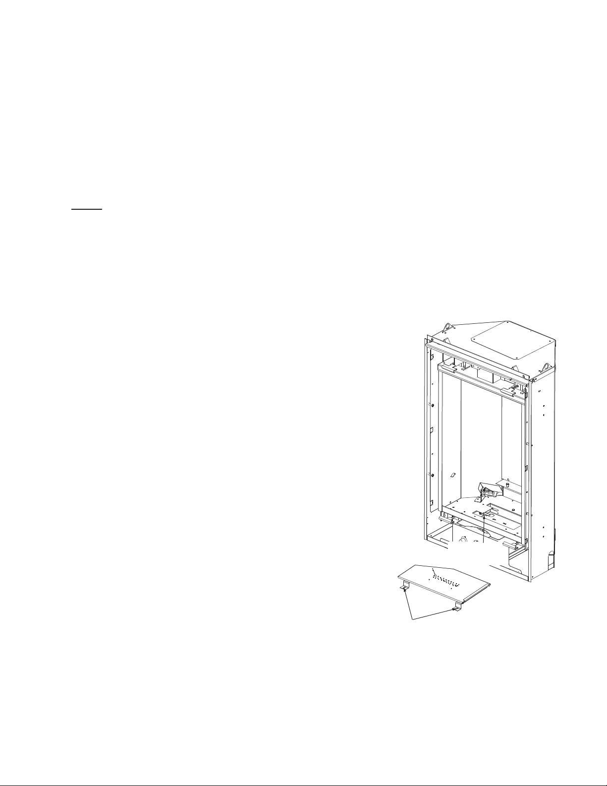
2.1 BURNER INSTALLATION
Before installing the burner, adjust the air shutter for the
desired fuel and install the fuel conversion kit if required.
See “VENTURI ADJUSTMENT” section.
A. Install the burner assembly ensuring that the venturi tube fi ts
over the orifi ce.
B. Secure using the screws provided.
ORIFICE
LOCATION
BURNER
ASSEMBLY
SCREW
LOCATIONS
W415-1002 / 01.25.11
Page 3
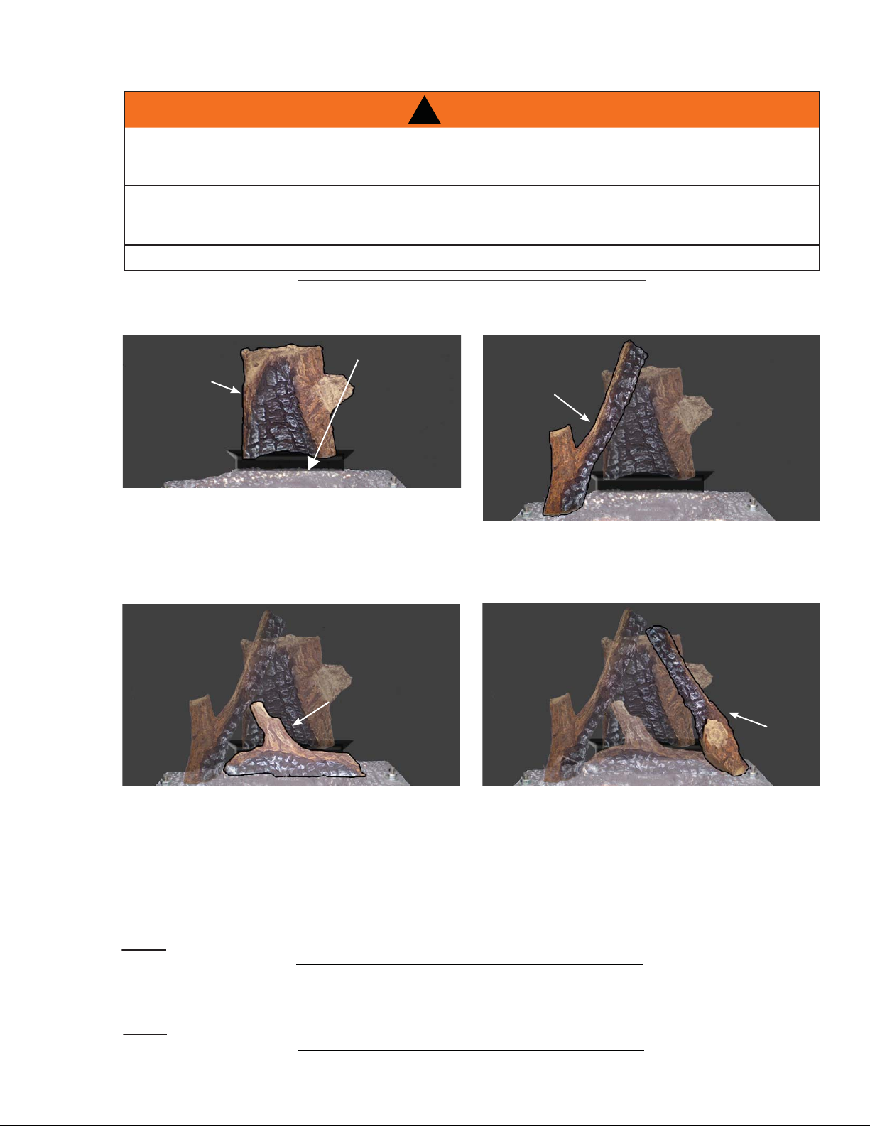
2.2 LOG PLACEMENT
S
FAILURE TO POSITION THE LOGS IN ACCORDANCE WITH THESE DIAGRAMS OR FAILURE TO USE
ONLY LOGS SPECIFICALLY APPROVED WITH THIS APPLIANCE MAY RESULT IN PROPERTY
LOGS MUST BE PLACED IN THEIR EXACT LOCATION IN THE APPLIANCE. DO NOT MODIFY THE
PROPER LOG POSITIONS, SINCE APPLIANCE MAY NOT FUNCTION PROPERLY AND DELAYED
THE LOGS ARE FRAGILE AND SHOULD BE HANDLED WITH CARE.
In order to assemble the log set, the glass door must be removed, see "GD19 INSTALLATION
INSTRUCTIONS".
!
WARNING
DAMAGE OR PERSONAL INJURY.
IGNITION MAY OCCUR.
BRACKET
3
76.1A
A. Place the rear log as shown, ensuring the
holes on the underside are placed onto the 2
pins of the log support.
C. Place the center log as shown, ensuring the
holes on the underside are placed onto the
two centre pins.
2.3 CHARCOAL EMBERS
Randomly place the charcoal embers along the front and sides of the log support tray in a realistic manner.
Fine dust found in the bottom of the bag should not be used.
NOTE: Charcoal embers are not to be placed on the burner.
2.4 VERMICULITE
B. Place the left log as shown, ensuring the hole
on the underside is placed onto the burner
pin. This will rest on the left side of the rear
log.
D. Place the hole in the underside of the right log
onto the locating pin, on the burner base and
rests against the rear log as shown.
E. Re-install the glass door.
32.1
prinkle vermiculite around the charcoal embers.
NOTE: Vermiculite is not to be placed on the burner.
33.1
W415-1002 / 01.25.11
Page 4

4
2.5 GLOWING EMBERS
Tear the embers into pieces and place along the burner ports covering all of the burner. Care should be taken
to shred the embers into thin, small irregular pieces as only the exposed edges of the fi bre hairs will glow. The
ember material will only glow when exposed to direct fl ame; however, care should be taken to not block the
burner ports.
Blocked burner ports can cause an incorrect fl ame pattern, carbon deposits and delayed ignition. Phazer
logs glow when exposed to direct fl ame. Use only certifi ed "glowing embers" and PhazerTM logs available from
your Napoleon® dealer.
3.0 ADJUSTMENT
3.1 FLAME CHARACTERISTICS
It’s important to periodically perform a visual check of the pilot and burner
fl ames. Compare them to the illustrations provided. If any fl ames appear abnor-
mal call a service person.
TM
3.2 VENTURI ADJUSTMENT
This appliance has an air shutter that has been factory set open according
to the chart below:
Regardless of venturi orientation, closing the air shutter will cause a more
yellow flame, but can lead to carboning. Opening the air shutter will cause a
more blue flame, but can cause flame lifting from the burner ports. The
flame may not appear yellow immediately; allow 15 to 30 minutes for the
final flame color to be established.
AIR SHUTTER ADJUSTMENT MUST ONLY BE DONE BY A QUALIFIED
INSTALLER!
54.3
VENTURI
BURNER
AIR
SHUTTER
OPENING
ORIFICE
49.1
Air Shutter Openings
LP 1/16”
NG 1/32”
W415-1002 / 01.25.11
Page 5

4.0 REPLACEMENTS
Contact your dealer or the factory for questions concerning prices and policies on replacement parts. Normally
all parts can be ordered through your Authorized dealer / distributor.
FOR WARRANTY REPLACEMENT PARTS, A PHOTOCOPY OF THE ORIGINAL INVOICE WILL BE
REQUIRED TO HONOUR THE CLAIM.
When ordering replacement parts always give the following information:
• Model & Serial Number of appliance
• Installation date of appliance
• Part number
• Description of part
• Finish
* IDENTIFIES ITEMS WHICH ARE NOT ILLUSTRATED. FOR
FURTHER INFORMA TION, CONTACT YOUR AUTHORIZED DEALER.
REF NO. PART NO. DESCRIPTION
1 W135-0322 LOG #1- REAR
2 W135-0324 LOG #2 - RIGHT
3 W135-0323 LOG #3 - LEFT
4
5 GL-662 LOG SET
6 W010-1653 PAN BURNER
7* W361-0016 GLOWING EMBERS
8* W550-0001 CHARCOAL EMBERS
W135-0325 LOG #4 - CENTER
COMPONENTS
!
WARNING
FAILURE TO POSITION THE PARTS
IN ACCORDANCE WITH THIS
MANUAL OR FAILURE TO USE ONLY
PARTS SPECIFICALLY APPROVED
WITH THIS APPLIANCE MAY
RESULT IN PROPERTY DAMAGE OR
PERSONAL INJURY.
41.1
5
1
5
3
2
6
4
Installation and repairs must be performed by a qualifi ed installer, service agency or the supplier.
W415-1002 / 01.25.11
Page 6

6
5.0 NOTES
W415-1002 / 01.25.11
44.1
Page 7

7
44.1
W415-1002 / 01.25.11
Page 8

8
W415-1002 / 01.25.11
44.1
 Loading...